
#Probe Design Ideas and Discussion
1 messages · Page 1 of 1 (latest)
 vagrant coral
current first prototype is printing, will have to adjust this thing once known what would be the problems in the design

 inner shuttle
vagrant coral
current first prototype is printing, will have to adjust this thing once known w...
I think that without special care in design, repeatability of the latch might be too low
vagrant coral
I'll have to consider that then
inner shuttle
vagrant coral
I'll have to consider that then
Like, the latch on the moving part will have a radius, the edge on the stationary part will have a radius. They'll be mismatched and with a significant friction, so they might not play well here
vagrant coral
I think I tried to acccount for that on the sketch

there's a miniscule space in there where the latch can hide when its sliding
I don't think that the latch being 1.5mm is way too strong yet though
inner shuttle
I wonder if this all could be done as a buckling spring compliant bistable mechanism, with switching force being significantly higher than microswitch force.
So, you'd ram it into something on top to deploy, then ram it into a bed mount for example to stow it
vagrant coral
I was also thinking about that
but I figured against it because it might be non-repeatable due to the stresses the plastic will encounter when its deployed
it might just deform it that results couldn't be repeated
inner shuttle
vagrant coral
but I figured against it because it might be non-repeatable due to the stresses ...
You don't have to let springs fully straighten out, you can make them hit a stop and be preloaded against it
 inner shuttle
Yep
vagrant coral
I also have a slight idea modification of the design where instead of stow default, it is deployed default
then you ram it to the bed to stow it
which is kinda similar to this, just that it requires a spring/rubber band
my only problem with that is that the idea doesn't have a way to deploy it again by ramming it into anything
https://www.youtube.com/watch?v=qTOFFN_0idA this seems to be a greatish design for that idea
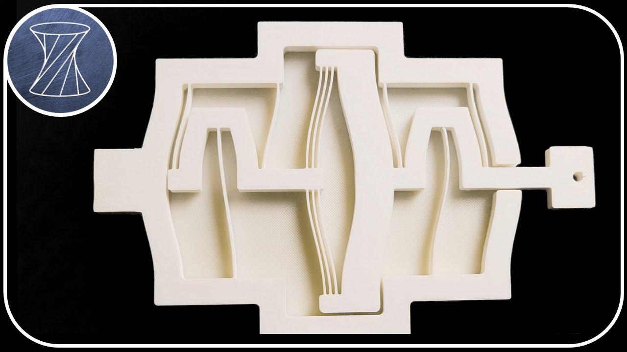
This video depicts a translational binary stiffness compliant mechanism that achieves two different states of stiffness by being triggered using a simple bistable switch. One state is very compliant while the other state is very stiff. The mechanism was designed by Reinier Kuppens while working in my lab at UCLA as a visiting scholar from Delft ...
 autumn summit
I think there was a mechanism you're looking for in that one sunshine vid where the printer electroplates layers after printing
it just bumped the top bar to deploy

Print Ionic-Thrusters, PCBs and Motors at home for just $100!
Check out PCBWay!: https://bit.ly/3NUeMHi
Files:
Printables: https://www.printables.com/model/662509
Thingiverse: https://www.thingiverse.com/thing:6345234
Huge thanks for the Cameos:
@integza - Wrong about tomatoes, but right about most other things!
@properprinting - Builds craz...
maybe put it upside down and make it more compact
vagrant coral
looks too flimsy tbh 💀
vagrant coral
vagrant coral
current first prototype is printing, will have to adjust this thing once known w...
got the thing printed in PETG roughly, the force required to move the flexing hinge is great, so it might be a great sign
the thing acts like a spring when overloaded, pushing the "rod" back whenever its way too overpushed
the only problem rn is the clearance issues it has when being stowed, the latch is barely getting in the way. Need more clearance near the end holding point
vagrant coral
vagrant coral
the thing acts like a spring when overloaded, pushing the "rod" back whenever it...
this only happens when I overpush it
the clicking force of the microswitch is lesser than the overload bending force, so it bodes well for the design
vagrant coral
wish me luck 🤞
 vagrant coral
I got the thing to work (sorry for crappy petg print, but phili is too wet, dried this yesterday for 8 hours to get 2 hours of decent print. would have taken a long time if I really had to dry it again)
still have to fix the crappy retraction on the sleeve
the general concept works, but currently its wayyy too long
sending the video here, but would take a long time due to crappy internet lol
vagrant coral
SERIOUSLY?!
 vagrant coral
oh hey
back
This is my current design for the probe

currently, my idea is to have two microswitch for this
1 for cutting off the pin to the motherboard for probe deploy detection
and 1 for bed probing
the design currently works with a bistable mechanism with 9mm of push down on the short sides will cause it to retract
and that is honestly not a bad tradeoff
the problem is that its made in freecad and freecad is just shit at this
oops I lost the data for the probe lmao
anyways yeah... the ratio here is 2:1, for 10mm push and then snap, it pulls it by another 10mm
can't believe my assumption though of the shallower spring leaf would cause a rigid-er spring is true
the deflection is easily doable on the loooooong side of the leaf spring
vagrant coral
vagrant coral
this is the final design for the intermal mechanism, now lets find a way to mount microswitches on this

the great thing about the added stopper is that it engages the tab to the spring, which adds a force that pushes it downwards, which prevents it from getting slack from the probe's microswitch click
its also a satisfying toy now
vagrant coral
 Updated Print Files below
vagrant coral
Not 1 by 1 with the original leaf spring, I had to modify the thing to get it to work with freecad's dumb constraint system so its not fully 1 to 1, but it should be close
Red is new, Yellow is Original

but does it really matter, its really close anyways
found a much closer fit, 30 degrees
 vagrant coral
1.5mm is perfect as a leaf spring
its light, yet its NOT that hard than 2.0mm
1mm is just a joke
it just boings with relatively light taps
I haven't tuned the probe yet, some slack would be evident on the bottom
vagrant coral
updated the spring, noticed it doesn't constrain with the peg
should now hook better to the peg
 vagrant coral
should now hook better to the peg
oh shit the spring has no clearance lmao
it just sheared off one of the pegs
 brittle inlet
vagrant coral
oh shit the spring has no clearance lmao
Gonna try my version now
vagrant coral
yeah, I'll wait
but I think I'll modify this again to just use 1 leaf spring, so one surface is a reference surface
that allows for more stability
brittle inlet
interesting
vagrant coral
and I'll probaby optimize the design more to NOT use pegs
pegs are a nightmare in FDM
brittle inlet
oh huh, why?
vagrant coral
shears off
brittle inlet
fair enough
vagrant coral
i'll replace it with a thingy that just uses a hole instead
then the leaf spring is the solid one
brittle inlet
curious what you come up with haha
vagrant coral
its just a minor modification
cut it in half
and optimize for FDM
that reclaimed space can now be where the wires can be routed 💀
brittle inlet
hahaha
brittle inlet
extended

mretracted

limit switch registers whether or not it is retracted/extended
pointy end gets hit by the bed
@vagrant coral
brittle inlet
please do!
vagrant coral
Nope, too loose. Made it clearance 0.2, too tight

im validating it first by printing
I should probably chamfer that other edge
lmao
vagrant coral
Added a slot on to allow for flextures
The top hole was made 0.2mm, shit too hard to push in
vagrant coral
i got the microswitches, and a hall effect sensor with magnet
two methods of probing
brittle inlet
vagrant coral
i got the microswitches, and a hall effect sensor with magnet
why hall effect?
brittle inlet
vagrant coral
Nope, too loose. Made it clearance 0.2, too tight
this design can't really flex as much as the last one, right? missing the pegs
inner shuttle
brittle inlet
why hall effect?
Because it drifts and that's fun 
inner shuttle
brittle inlet
this design can't really flex as much as the last one, right? missing the pegs
I still wanna see buckling springs here
 vagrant coral
brittle inlet
this design can't really flex as much as the last one, right? missing the pegs
yeah, which I had issues with in the fabrication
the side walls interlock, adding a ton of friction
vagrant coral
inner shuttle
Because it drifts and that's fun <:vaulthah:597787241812852736>
I just bought jt because its cheap
$1 hall effect sensor and $0.5 per magnet
but I intend to do microswitches first, those are really easy to work with
a hall effect sensor would actually be really trivial to implement, I could go really thin leaf springs which has a slack at the end
(its honestly just the bltouch but without the microservo lmao)
vagrant coral
inner shuttle
I still wanna see buckling springs here
my question here is how could you implement it
inner shuttle
vagrant coral
my question here is how could you implement it
Exactly how you have yours right now, have these buckle and that's how you get a bistable mechanism
vagrant coral
inner shuttle
Exactly how you have yours right now, have these buckle and that's how you get a...
so those are rigid pins and the walls flex a bit
quite interesting
my question would he how would you control the amount of distance travelled
mine currently can do 10mm which is enough to lift it off the bed I hope
I've just noticed I need either preload to get that thing to pull back the probe harder
or the tab has to get longer
making the tab longer is easier so I opted for that
probably close to the final design of the internal
ooo nice, it requires 4mm of push to travel 10mm 
that is certainly workable
damn someone should really teach me how to properly design shit for 💀
trial and error is fun and all but it takes time lmao
brittle inlet
inner shuttle
I still wanna see buckling springs here
Good call!
inner shuttle
vagrant coral
my question would he how would you control the amount of distance travelled
There's a bit of math involved. You just can steal existing design as well
inner shuttle
brittle inlet
Good call!
I've been lobbying for these since the beginning
vagrant coral
inner shuttle
There's a bit of math involved. You just can steal existing design as well
well.... need math lol
vagrant coral
currently I'm sticking with that design
not final though, still missing the other microswitch
brittle inlet
Nice!
vagrant coral
oh shit
remember the hook design I was saying fir corexy?
Why don't I just do that
that removes the travel required
oh, yeah I forgot, that... needs an endstop
...if it needs an endstop, that's basically two switches already, so why not
brittle inlet
vagrant coral
Why don't I just do that
yeah why not
brittle inlet
vagrant coral
...if it needs an endstop, that's basically two switches already, so why not
why?
vagrant coral
brittle inlet
why?
that needs an endstop precisely just so the probe doesn't crash on the bed
you can still set the Z axis home to the probe, its just that the endstop should also be wired to the probe switch
vagrant coral
Probe Design Ideas and Discussion
vagrant coral
vagrant coral
OH
WHY DIDN’T I USE MAGNETS
That would make that thing compact as heck
There's also this:

It wants to deploy but it can't because its blocked by a pin
To trigger it, you need to send the probe at the edge of the printer, that will deploy because the pin gets lever'd away by the push block
now the issue is that it might not be repeatable, so I guess we need to add magnets on the underside of the spring
That will be hard to push back by the probe considering its going to be resisted by both the spring and the magnet
but if we do full send the probe into a special spot in the gantry, it can now stow away since the gantry is heavier than the spring and the magnet force
but then again this is just the same thing as the original spring loaded thing, just inversed
autumn summit
you almost have a strykepoint like that
vagrant coral
autumn summit
you almost have a strykepoint like that
at least it works with bedslingers I guess
That thing doesn’t seem like it does
time to make it really compact by sticking a pen shaft on it lol
vagrant coral
now I just need a probe stow retention
which should be similar to the first design
vagrant coral
vagrant coral
vagrant coral
I know, we steal the tube of a pen, and then add the spring in line to it!
autumn summit
maybe magnets?
also make the bottom tip stylus shaped like unklicky or use a screw/pin imo
more accurate, less heat transfer
vagrant coral
autumn summit
also make the bottom tip stylus shaped like unklicky or use a screw/pin imo
I will do that, but I did the flat thing simply because I was trying to limit the motion of the thing
vagrant coral
autumn summit
maybe magnets?
the magnet spring type sounds like a nice idea lol, but idk. I'll try the spring being in between of the thing first

its nicer to have the forces be in line with the probe so it doesn't induce a rotation
autumn summit
you could use a pin and brass bushings
 vagrant coral
couldn't you just use a PP straw
autumn summit
idk, just thinking about repeatibility
vagrant coral
quite fair, but I was thinking it would be funny if you can source almost all of the parts off a 3d printer and a pen
a PP straw usually comes with the pen well, and it has quite low coefficient of friction
its also quite flexible if the PP is sufficiently big
will it last though? Probably not. It's not as good as PTFE
I love how this is kind of stupid though
vagrant coral
OOPS WRONG SPRING DIRECTION LMAO
vagrant coral
this should be the final prototype I think

that mid point is cursed
2.23 mm
I’m worried about assembly but seems like if I put it 45degrees, it fits
vagrant coral
vagrant coral
the magnet spring type sounds like a nice idea lol, but idk. I'll try the spring...
this test was made on this tho
vagrant coral
vagrant coral
autumn summit
I'd worry about the fan mount blocking flow
temporary mount
I have no place to place it yet
it’s meant to be attached probed and then evaluated

it not being rigid mounted really close to the vroller + tremendous spring force causes repeatability to be low
but good enough for the first test
uh what

fully lifting the probe (NOT FAST) causes good accuracy?!
truly an engineering tri ven diagram
okay how many samples should I do
I’m gonna let it run for a while
f it, 500 samples
 raw edge
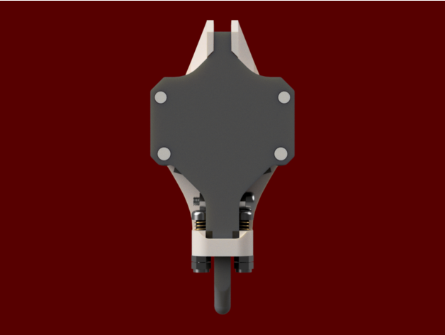
my 2 cents this looks to be a bistable bed probe project, similar to https://www.thingiverse.com/thing:4736440
Thingiverse
Part Counts:1x Base1x Plate1x Probe1x Mount2x Probe Pin2x Probe Arm2x Base Arm2x 4mm diameter 12mm long spring2x 4mm diameter 2mm long spring2x M3 Nylok Nut3x 16mm M3 Bolt5x M3 Nut8x 6mm diameter 3mm thick neodymium magnet (optional)MechABL is an affordable DIY auto bed levelling sensor with a mechanicalretractable probe. I designed MechABL main...
autumn summit
not bistable tho and a lot simpler
vagrant coral
raw edge
my 2 cents this looks to be a bistable bed probe project, similar to https://www...
we did go that route, but my main issue with this design is that how would you undock it
autumn summit
vagrant coral
I have no place to place it yet
behind the X extrusion
vagrant coral
autumn summit
behind the X extrusion
probably
vagrant coral
raw edge
my 2 cents this looks to be a bistable bed probe project, similar to https://www...
yep he has to push it down
autumn summit
he could go to the top of Z to activate it
vagrant coral
its possible to send it upwards towards the Z to undock it
the issue with that is that you have to sense though if the probe is attached
possible with klipper
every 3mm move upwards, you check probe pin, then push up more if not attached
hmm I should probably find a way to make this run typical pen springs to make it accessible to people using household items to make a probe
2 pen springs side by side should give enough force I guess
currently the spring there is harvested off some phone mount
good enough for a demonstrator tho