#Flashing Firmware SKR3
1 messages · Page 2 of 1
 shy tinsel
 austere kayak
okay
shy tinsel
and we will need the distances for motion + the probe info+ whatever else
inc the motor configuraiton
from the ender 5 example
basically we need to combine it
austere kayak
some copy paste shit
shy tinsel
so we have the ender 5 example re writtenw twith the pins and shit fomr the SKR3 example
yeap
copy pasta from one 2 other
to make ours
the staring example for ENDER 5 go voer it
and make sure it has the runout sensor and probe
etc
if not things will get more complicated
but if it has all that already even better
I will look for an actual profile ready to go
as that will save time but also I did learn A LOT about myprinter doing it manually so
this is worth a watch https://www.youtube.com/watch?v=iDpeHyMkaJk
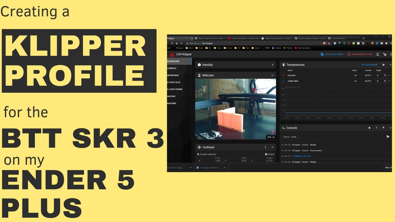
In this video, I will be sharing the Klipper profile I created for the SKR 3 running on a Creality Ender 5 Plus.
My GitHub: https://github.com/minimal3dp/klipper
References:
-
Klipper - https://github.com/Klipper3d/klipper/
-
BigTreeTech (BTT) SKR 3/3 ez - https://github.com/bigtreetech/SKR-3
-
Ender 5 Plus:
https://github.com/Klipper3d/kli...
austere kayak
ill look over the ender 5 example
there is no probe or runout sensor included sadly
ill install the config for the ender 5 pro and see if the values match
shy tinsel
We can probe steal his ender 5 plus if he shared it

GitHub
My various Klipper configs. Contribute to minimal3dp/klipper development by creating an account on GitHub.
for 3ender 5 plus
WE can fucking steal that
and just change whatever theheck we need too
saves us much time
its minimal so its all in 1 configf
I went over it
austere kayak
can we continue this tomorrow. it is 4:25am my time
ill install that config in the mean time. have everything ready for when we come back
shy tinsel
Stepper motors ☑️
Drivers: ☑️
Probe : ☑️
Bed and Extruder: ☑️
Z Tilt & Screw Tilt ☑️
interesitng enough you should be able to wire your motors for Z titl
Stock display check
ok yeah we need to find anoter one
the plus is very differnt
has more motors etc
shy tinsel
austere kayak
can we continue this tomorrow. it is 4:25am my time
np np
I will do my best to find a profile for you
or at very least
I will take the examples and make a semi finisehd SKR3 one for u
so that way u dont have to do the mix and match thing we can just jump into testing
You will want this check list as well https://www.klipper3d.org/Config_checks.html
u will run thru that check list before you even attempt to operate the printer 😛
last thing u want is for something to go wrong and break shit
its one thing to have to fix a small issue its a bad thing if motors try to move in opposite ways and bend shit
austere kayak
this is the example conf for ender 5 stock
 shy tinsel
Yeah I am going to grap the examle config for ender 5 stock
austere kayak
but this is for the ender 5 plus
 shy tinsel
and marry it wit the SKR3 generic config
the plus is too different
I mean it uses 2 more steppers
for a start
because it can auto tram thebed
it has more motors
wiring will be different
austere kayak
ah
shy tinsel
its more mess for us
to work with
easier if we just use base or pro
same dimensions
same setup
minor differneces
I have made mine from scratch so you are lucky
U have someone who can write this for you and use two configs to do it
austere kayak
well i really appreciate you working with me on this. i know i wasnt the nicest on our first interaction. been a long day
shy tinsel
its fine
you have done more than I expected
a lot of people are not tech savvy
and cant work out backend shit
I just didnt wanna see u give up man
the whole hobby
austere kayak
ive been dabbling in this sort of stuff since i was 12
austere kayak
it was hard getting my hands on that pi. during covid as well.
shy tinsel
Marlin is has its job its not terrible but for tinkering in its a pain to keep flashing
granted marlin code is less dodgy
plenty will argue about what code is better
ngl
klipper is potentially faster fact
austere kayak
i prefer customization over anything. thats why i loved using android
shy tinsel
then u want klipper or reprap
marlin is ok but its more about user use than endless fiddling
I started with Marlin aswell
i flashed custom marlin it worked but making my own did not always work
I flashhed with pre made CUSTOM source with more options than stock marlin
But my dream was klipper form day 1
I set out with a $400 used printer
austere kayak
it sucks that there are so many printer types, its tough finding updated configs for a specific printer
shy tinsel
it was mess bro u should have seen it
I had no FUKCING idea what I was doing
I learn3ed this hobby from ground up
using printer first after I tidied up some wiring
to marlin then I went off and got a custom board
I think to myself this will be some work not too bad
BOY I was wrong
3 months down the rabbit hole
I finally powered it on and tried to test motors
issues
corrected it
finally homed it
took me 2 days to sort out a driver issue
turned out I did not have the fucking drivers powered whole time
austere kayak
if i were to upgrade all my motors to nema 17, will i need to recompile?
austere kayak
i was thinking about getting rid of my stock steppers
shy tinsel
motors are a controlled by the function stepper
all the info about your motor for that axis
is like this

See I split my configs up into components
I can do same for you if u like
will takeme 15min more effort
Its just taking a bunch of shit from one config and putting into its own standaone file
^ that is all my motors
is really that simple
you read the info about ur motor
input th9e NEW data in here
austere kayak
thank you, that would help a ton at understanding it a bit better
shy tinsel
save and reboot
and if all go well motor work
some times u gotta change the dir pin
the ! means reverse
so if for exampl motor goes left and it should GO right
u add or remove !
to change the dir
austere kayak
can you fry the steppers with the wrong pin number in software?
shy tinsel
this is based on some motor wiring
sometimes the input signal will need to be revesed
for correct direction
Wrong pin # wont do shit
just means motor wont respond
austere kayak
oh cool, so no real risk at this point
shy tinsel
it will do noting
voltage is all u want to worry about
vltage and things like speed
rotation distance is how many steps a motor turns
u can expirment
austere kayak
and i will
shy tinsel
but there is a nuimber u need to work ok
mircostepping is based on how good your board is able to keep up
processing
higher numbers = smoother steps
less noise
there is sicence around it but yeah
u can do upt too 256 potentially
it smooths out the motor inbetween steps
austere kayak
can you make sick timelapses on prints with klipper?
shy tinsel
posiont min an max well that easy
that means the min max of the axis
how far can it go before it says NO
going more not allowed
this is so u dont crash all over place
u can find it tou easy tho
like for X axis on mine
I use the move command to move printer head ALL way to one side
until it hits the end stop
I not that down as a negative number
this becomes the min
I move it all way over to end until I hear it crashing into the side of ganatry
I subtract say 5 from that number
and thqats my max
then u do same shit for bed
u move nozzle around until u find how far u can go in each side
austere kayak
yeah that sounds good when it starts screeming at you that there is no more rail to travel
shy tinsel
and nozzle is still onbed
etc
thats what I mean by manual
its not HARD per say but takes time
and iterations to get spot on
coz u will have to go and actually move the print head around
getting all that shit
then u need to find your probe offset yourself etc
this is distance from probe in the X and Y to the nozzle tip
you can do that easily ish to
austere kayak
im sure it would be easier to diagnose the problems than wondering why the e stepper stops spinning mid print in marlin for whatever reason
shy tinsel
u basically lower nozzle onto the bed man
put some paper down mate
mark the paper
with a dot
lower the nozzle onto the dot
mark down the coordniates
move print head and deploy the probe lower it onto the dot
same deal mark th at down now u simply subtract the differnece
between the probe corrdinates and the nozzle
that is your offset
if that makes sense
you can use a cube or anything with a point u just want a small targer to align it onto
for example if the X for my nozzle was 148 and nozzle was 135 I would do 148-135=13
my prob X offset is -13
anyway u prob wont have to calibrate it if using a stock printer setu
I had to it all manual because I had a custom shroud and probe mount and everything lol
austere kayak
No, but that’s useful for when I do eventually get a probe
shy tinsel
yeah
thats how you find out the distanced from nozzle to probe
it is needed to calibratre the probe offset
but that is how u do that
now if um
if your printer bed is hooked up with individual motors
austere kayak
Im not in a good place to start buying things. This skr3 board really set me back. But I couldn’t do anything with my last board
shy tinsel
if you have ytour gantry hooked up to individual drivers
and motors
u can auto square that
with z tilt
th at is using the probe over various area of bed to check your Left and right side of gantry
and use math to auto lmake the gantry straight
now its harder to setup with corexy coz more motion in place
but on yours
I think your gantry for Z is just two motors yeahj?
or maybe it does nto move at all I dunno
I have a cartesian printer
so my gantry is two steppers and my bed does not move at all up or down
shy tinsel
austere kayak
Im not in a good place to start buying things. This skr3 board really set me bac...
U have a lot of freedom now
you can use the the GPIO pins on the pie and board if u wantred to run whole thing thru a ribbon cable lol
you can basically use most free endstop ports for other devices
they all provide 5-24v
depends on the PSU and board jumpers
Klipper is freedom
I mean here are my TMC2209s

U can turn stealthchop on or off
0 = off
999999 = always on
1 = on when idle and printer is not moving
so its silent when just sitting there but you get the benifit of all your motor torque when its actually printing
I just prefer mine to be silent
run current can go up to I think 1.5 ish
or 2.0
depends on dirver
thats how much power is going to your motor
more power u can probably put more strain on it as in faster movement
before it misses steps
but it will run hotter
u will need to add a fan over the TMC drivers blowing if u want to run current more than 1.2mv
Mine have heatsinks aswell but no fan so I can't run them hotter atm
They will thermally shutdown safely tho
anyway man
let me handle the config side of it I can do that for you
I will just start you off with a married SKR3 config + ender 5 stock config example
make any minor tweaks for sanity then 2moro u can go about testing and tweaking
I will send you a zip file with the entire setup just drop the whole lot into your printer and you will need to change the MCU ID to that of what you got from earlier but then it should be ready to run thru klipper check list
I will give you a video guide as well as its same one I used to first test my printer before trying to home it this video just is informative steps to check on your printer before fully sending motion commands to it
The configs should not take me more than about 20min
I have been messing around with configs for all of last 3 terms of 2023
I don't mind helping, I like this kind of thing, plus I rather give someone a nice easier to work with setup then having it all thrown into printer.cfg and having to all commented and tidy
If we run into issues and its likely we will they should be just checking your cabling vs the pins being used and checking if the pin needs a pullup or down or if the motor has to be revesed etc
most of it should just work
provided the board is all connected up to the pins the config is expecting
it maybe true that where u pluged your axis might differ to the axis pinned in config but thats simple stuff to fix
again we dont need to re compile or flash anything we ust change the connector port or change the pin in the config to suit
 shadow cobaltBOT
This post has been closed due to inactivity.
This post has been inactive for over 1 hour and so has been closed. To reopen this post simply send another message.
shy tinsel
Progress


Yeah Look I may have just basically wrote it all from scratch using an example I found for a SKR3 Mini 3.0
I found that here https://print3d.world/how-to-install-klipper-on-ender-5-with-btt-skr-mini-e3-1-2-bmg-direct-drive-and-abl-probe/

I decided even though I have plenty of processing power with my SKR boards that my nerdy self had to give Klipper a try. I was experiencing lots of print defects with Marlin, and I had heard the kinematics in Klipper were much better. I embarked on an all-day journey on my day off to … How to Install Klipper on Ender 5 with BTT SKR Mini E3 1.2, ...
You will need probably calibrate the exruder rotation I made full configuration notes as I wrote all this so you should be able to easily find what you need for common settings and tuning
I have yet to change all the pins but its 80% done from here.
Oh yeah I include customised macro's and things that, we may get you just install KAMP aswell while were at it so yo uncomment a few lines and avoid worrying about some things.
shy tinsel
Oh yeas we don't want to have to have to remember a whole bunch a common pins for the board now do we KEK
Lets make them human readable
WIP
shy tinsel

Please double check your board wiring, for hotend heater and thermistor I will configure it for he0 and th0 🙂
shy tinsel
Aight I spent about 2.5 hours on this but this looks to me close enough to baseline test with.
austere kayak
Just woke up. Damn dude you went crazy on this. I can’t thank you enough
austere kayak


okay, so i figured out the drivers issue. but theres no way i can figure out what this means

 misty ivy
austere kayak
okay, so i figured out the drivers issue. but theres no way i can figure out wha...
kinda shot in the dark since im not reading the rest of the chat, but board_pins EXP1_2 might be missing a comma at the end
 misty ivy
in your heater_bed sction add
pid_kp: 0
pid_ki: 0
pid_kd: 0```
and add a todo list before printing to do a PID tune to set the values misty ivy
use tab to move them over
austere kayak
same issue

 misty ivy
send how the whole [heater_bed] section looks
austere kayak
 misty ivy
thats not the [heater_bed] secion, should have the brackets and underscore with it
should be in the printer.cfg if its setup normal
 misty ivy
you run a save_config after that? is there a section near the bottom about an autosave section
if not you can take out the # from ther
there*
austere kayak
this was already on the saved config
ill take the #s out
ooh, were getting somewhere

had to do the same for extruder pid
misty ivy
you messed with the [mcu] yet?
austere kayak
no i havent
misty ivy
you ssh into the pi or have control of it elsewhere?
austere kayak
usb-Klipper_stm32h723xx_22001B001651313238353730-if00
found the correct usb id
now im getting a new error

 misty ivy
try adding the comment # before all of those, leave the EXP ones alone
austere kayak
im sorry, what is EXP?
misty ivy
the part below thet
    EXP1_2=PB0,EXP1_4=PE8,EXP1_6=PE10,EXP1_8=PE12,EXP1_10=<5V>,

    EXP2_1=PA6,EXP2_3=PE7,EXP2_5=PB2,EXP2_7=PC4,EXP2_9=<GND>,
EXP2_2=PA5,EXP2_4=PA4,EXP2_6=PA7,EXP2_8=<RESET>,EXP2_10=<NC>```oh okay
misty ivy
we need these i think, not sure you want the rest of them
austere kayak

 misty ivy
whats all in the [mcu]?
austere kayak
misty ivy
not sure why its erroring in mcu, but in the [probe] change pin to PC13, kinda guessing since it was that in the board_pins part
austere kayak
 misty ivy
ah, the commented out section from the board_pins had the pin names, but looks like they couldnt get referenced
go through that block and find the pin, then replace it where the error happens
ex x_uart is PD5
not x_uart_pin in tmc2209 stepper_x
austere kayak
so i uncommented them same issue as before


do i need to remove enable pin or the step pin on the sections?
misty ivy
comment them out, and transfer the pin name/number to where it is being referenced, where its being used cant see into that file im guessing
[tmc2209 stepper_x]
uart_pin = x_uart_pin
to
[tmc2209 stepper_x]
uart_pin = PD5
then save and repeat until a new error
 misty ivy
[stepper_x]
step_pin = x_step_pin
looks like its in stepper_motors.cfg
the whole config got made into a few files somehow
austere kayak
`#############################################################################################################
STEPPER MOTOR CONFIGURATION
#############################################################################################################
This file contains pin mappings for the BIGTREETECH SKR3
[stepper_x]
step_pin: x_step_pin
dir_pin: !x_dir_pin ; if move direction in wrong direction remove/add ! in front of pin
enable_pin: !x_enable_pin
microsteps: 16
rotation_distance: 40
endstop_pin: ^x_endstop_pin ; Endstop pull-up use ^ for pull-down remove ^ in front of pin.
position_endstop: 235 ; Endstop Position
position_max: 235 ; Axis Move Maximum Position.
homing_speed: 100 ; Maxiumum Move Speed while Homing.
[stepper_y]
step_pin: y_step_pin
dir_pin: !y_dir_pin
enable_pin: !y_enable_pin
microsteps: 16
rotation_distance: 40
endstop_pin: ^y_endstop_pin
position_endstop: 235
position_max: 235
homing_speed: 100
[stepper_z]
step_pin: z_step_pin
dir_pin: !z_dir_pin
enable_pin: !z_enable_pin
microsteps: 16
rotation_distance: 4
endstop_pin: probe:z_virtual_endstop
#position_endstop: 0
position_max: 300
position_min: -10 ; Minimum Z Axis Position
[extruder]
step_pin: e0_step_pin
dir_pin: !e0_dir_pin
enable_pin: !e0_enable_pin
microsteps: 16
rotation_distance: 7.710 # Manual Calibration may be required for optimal tuneing ESTEP/Rotation conversion needed.`
what would be a valid pin name. change those the same as before?
misty ivy
PD6, from that commented out section
any reason to not use the default config for skr3? should be easier and get you like 90% the way there https://github.com/Klipper3d/klipper/blob/master/config/generic-bigtreetech-skr-3.cfg
austere kayak
@shy tinsel compiled it for me with an ender 5 config he found
misty ivy
now that sounds annoying, im better at toubleshooting than setting up from scratch
ill be back later, gotta start my own project
 shy tinsel
Yeah there will be some clear issues wr need to fix
I didn't have access to printer etc
Or able to test this condfig for typos
austere kayak
ah okay
austere kayak
im glad i was able to set it up without any extra guidance
shy tinsel
Because I wasn't happy with making a shit one
austere kayak
just need to change things
shy tinsel
I see the issue
Dome of pins dhare same pin bt accidentally
It's huffing a huff about it
I documented the thing pretty well at least lol and i gave you the pinout image
So if u wanna change anything y don't have get lost trying
austere kayak
someone on the klipper discord suggested not using aliases
shy tinsel
I mean yesh they have there benefits and not
You can strip a few of them out if u wanted too
I'll double check these thing bow im uo
Sorry i have not been up long yet
austere kayak
is it there to quickly reference other configs for fast changing
shy tinsel
misty ivy
any reason to not use the default config for skr3? should be easier and get you ...
Because I used the diagram from the manufacturer and a ender 5 model printer for SKR mini 3
I did incline the baseline config iirc
I just did the layout very different
Which may look odd but I've done it this way plenty of times
The generic thing stuffs it all into 1 file and only thing we xare about is the printers actual motion mechanisms and limits along with the boards pinouts for the control board which I just got from the github and the included image file
Of the board schematic
I was afraid the aliases didn't work
That wa my main concern
I mean I can test and fix this on my machine
I'll just have back up said machines configs first lol
It's not screaming about anything major at least
shy tinsel
austere kayak
im sorry, what is EXP?
The display ports for seriel displays like your stock display
austere kayak
oh okay
shy tinsel
misty ivy
not sure why its erroring in mcu, but in the [probe] change pin to `PC13`, kinda...
Yeah ok I can see a few issues here
I have all my printers split up like this so that I can easily identify sections of the configuration and not have to scroll thru a huge ass printer.cfg full of everything
plus it makes it modular you can commend in out stuff u need
austere kayak
ah i see
shy tinsel
Some variabeles NEED to be in printer.cfg others can be moved out for example boht my printers I have setup in this way
and they all work
There are some errors above I noticed that relate to possibly bad headers for the sections or names for the pins
I can double check against my working configs
since the large portion of the printer.cfg came from some random dude
on reddity
I dont know if it was even working but it appears to be all the motion and setup we needed
for that model printer I just cut it up and moved things around
90%$ of your errors are about the pins
Now something fishy is going on there with the alieses I will need to actualy diagnose that
until it shuts the fuck up I can do that on one of my printers and just sacrifice one of them for debugging this
If the generic board file has alises well I can just use those tbh
What I did was read the png file I sent along with the github
But its not uncommon for alises to throw errors like this, it MAY be easier to just use the pin name directly
austere kayak
hmmm
shy tinsel
however my other printer uses alises like this and works
I stole some if it lol
thats why the alises are like that I didnt have to change the names for all the pins fully I just had to write the alises with correct pins for SKR3
and add anything maybe needed later
I never expected this to work the first time lol
they never do unless they are official profiles made for a machine
shy tinsel
austere kayak
This error tells me a pin is shared between another pin
probably a typo on my part
shy tinsel
austere kayak
All of these are telling me its not reading the alises correctrly
because the MCU talsk to the board the board replies back if a pin is available and it board says N O
we dont have a pin called that, but the alieses have it, and a sudo name was given for that pin its just not using it why that is well yet to be seen
because my other printer uses the SAME aliases names and it works just fine.
again I won't know how this looks until I get it onto a printer
It will defo throw errors if there are spacing errors in the boardpins.cfg
it won't detect certain alises if they are not formatted correctly
I did all this is VS code so I didn't have it on a printer to check for parsing issues that is my bad
shy tinsel
austere kayak
Ok so this is easy
Linux is case sensitive obviously I have the file name lower case and the folder is upper case my mistake
shy tinsel
austere kayak
okay, so i figured out the drivers issue. but theres no way i can figure out wha...
This is the root cause of the alises problem
it can't parse the alises or some of them which making every alises name not work
shy tinsel
austere kayak
like this?
This part is irrelevant dunno why jack made u change it
PID is handled by klipper like Z offset once you run a PID tune and make your Z offset BOTH of those will all be commented out
that u dont have to touch
This a list of all the shit working printer will do

that section is created automatically
by the printer
austere kayak
i had altered back to exactly what you sent me earlier. just a restart
shy tinsel
However THE SECTIONS HAVE TO EXIST in the printer.cfg
if they don't you may get a failed to save PID value or Z Offset will be thrown
that is why they are there but their values are meaningless since whatever was defualt is going be commented out your machine when you actually calibrate them the 1st tmie
@austere kayak So here is what I am going do, am going to config backup of my printer and I will fire this set into it and debug all those pesky problems until I have it load and shit
however I know for fact its going to error on me as the pins are not what I have so best I can do is TRY to get around it by changing a couple pins temporarily
to get past some things that the board WILL need to actually boot
If the onyl errors I get is ADC out of range etc then it will prob work for u
it should in theory error on parasing erros first
austere kayak
if you guide me from there, i can try to change the pins to mine myself. it would be good to learn some
shy tinsel
before throwing actual hardware faults at me
shy tinsel
austere kayak
if you guide me from there, i can try to change the pins to mine myself. it woul...
Yeah I sent you baord diagarm png
looking at that you will see what I have done
also I used this

GitHub
Contribute to bigtreetech/SKR-3 development by creating an account on GitHub.
if u scroll down

They list all the pins in a semi spreadsheet way
However I prefer looking at the board diagram
but I did double check some things in the list ^
All in all I knew we would maybe run into parsing issues since I could not verify if the tis config was going too actually load lol
but its nothing we cant fix 90% of work is done at this point we just get klipper happy with it and load it
then go from there
YES we could have used the generic bigtechtree SKR3,cfg
but it would not have been moudlar it would have been missing things for your printer we still would have had to go and do fair bit of it
The only differnece is I split it up into speerate files for ease of use, so u cna just open the steppers file to adjust steppers instead of scroll a long ass file and find where u put that data tobegin with
austere kayak
awesome
shy tinsel
it was for readability mostyl
and modularity
the headers for things are same as that for the generic exmples
that stuff does not change
its just layout different
I should actualy read it tho anyway
as it will 100% clear up any pinning issues we have
if any
in case I mis understood the pins on the board
Also on your end you need to DOUBLE triple check
the board is cabled accordingly
but thats another issue
For example if u find something NOT to work first try rversing the pins
if not then couble check the board i matching the config file
and change whichever u more comfy with
I had no way to know for exaple what TH or Heather port u used
for what
I just weent with HE0 as extruder heateer
austere kayak
im pretty sure it was e0 and h0
austere kayak
it has two for a toolhead switcher
shy tinsel
there are two yeah
I did ad the pins for everything
all the thmerisots
and all fnas
and all the heaters and extruders
all of it has pins
some are just not used
austere kayak
if i wanted to use the other ones in the future it would be an easy config change
austere kayak
ahh
shy tinsel
they all are there in boardpins
I added all your extra ports for things
that I could visually find at timen
that are common and maybe wnated like all your th and heating ports are in there
RGB header is there
I did not relly understand your prob situation I will have to double check
generic example and what u did cable wise
since BLtouches have 3 -4 pins
Your borad oddly uses 2
so I am not sure how they expect you to use a touch probe
with a servo pin
unless thats what the SERVO pin on board is for
I did add that btw
my board simply has a PROBE port with 5 pins
austere kayak
yeah that is weird
shy tinsel
for direct connecting the standard BL cables
austere kayak
the axis stops also have 3 pins where the wires only have two pins
shy tinsel
yea I expected that
becuase Voltage is not needed for endstops
but can be supplied
since u can use un used endstops for other hardware
since it relaly is just a restor pin, gnd and power
they can be used for ANYTHING not just endstops
that need VIN and a sensor wire
just the phsyical endstops only need GND and the pullup sensor pin
so 2 wires
austere kayak
hmm
shy tinsel
they its not uncommend to seem wired in a 3 pin connector only using 2 wires
all mine are same I wired all mine myself but I added 3 pin connector as it would allow me to use the connector slot to lock the header in there secure
I could hve just a dupont connector lol
wiht 2 pins only
Not unusual dont worry about it lol
endstops dont make use of 5v pin
they make use of Ground and the pullup pin
austere kayak
pullup pin is the one in the middle or the opposite side?
shy tinsel
pullup pin is the one with the ^ in front of it
in your configs
I documented it so you knew what to do if things did not behave
Some things dont pullup but ah ytour sotck printer said it was a pullup so I made it a pullup lol
basically you can use the endstop free headers for shit like a klacky probe
that needs the 5v power or could use the 5v power
its just a 5v power rail in the connector endstops dont use it but other hardware that MAY share the header slot will
if you DM me I can stream working on the configs if u want
possibly even voice chat if u need
up to u
austere kayak
just sent a dm