
#Inductive Sensor
1 messages · Page 1 of 1 (latest)
 golden haven
 hallow torrentBOT
golden haven
Guys! need help. It is necessary to connect the inductive sensor to the 3D print...
AI Help
It sounds like you need to configure the firmware on your MKS SKIPR motherboard to recognize the inductive sensor as a homing or limit switch. Here are some steps you can follow:
-
Make sure your inductive sensor is properly powered - it requires DC 6-36V.
-
Connect the sensor's brown wire to the positive (VCC) pin on the board, black to the signal pin, and blue to the ground (GND) pin.
-
Open the configuration.h file in your firmware and look for the section on homing or limit switches.
-
Uncomment the line for "z_min_endstop" and set the value to "probe". This tells the firmware to use the probe input as the Z minimum endstop.
-
If you're using Marlin firmware, you also need to enable the "Z_MIN_PROBE_USES_Z_MIN_ENDSTOP_PIN" option.
-
Save the config file and upload the new firmware to your board.
-
Test the inductive sensor by manually triggering it with a metal object while sending a M119 command to check the endstop status. The status should change from "Open" to ...
WARNING: This response is AI generated and may contain errors.
 grave gale
ok, so I'm not exactly certain but the important thing is to get the schematic for your probe and connect it correctly to your motherboard, for which you will also need a schematic - you can google for both of those things. Typically there is a sensor connection and a probe connection; there may be an additional one - maybe ground I can't remember
I'm not familiar with that motherboard or probe though so that's the best I can offer at present without googling for you
I would search for e.g. '<insert motherboard name> schematic' and also '<insert probe technical name> schematic'
then compare and contrast
 noble onyx
Ok so the board is probably providing 5 VDC and as per the spec of the sensor it needs 6 to 36 VDC
SO you need to power it from your PSU then step down the signal voltage
Theres a few videos out there how to do that >> https://youtu.be/il9bNWn66BY
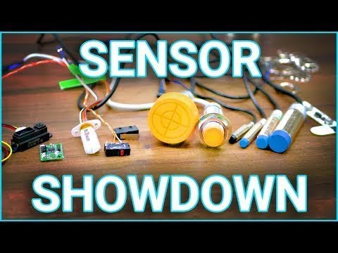
There are many options for a 3D printer's bed sensor and even more misconceptions about what they can and should do. So after a ton of testing with a custom-built precision test apparatus (TM), 9 myths about these sensors have been examined - and we got a ton of data about how precise each one can be!
🛒 M8, 2mm inductive sensor (5V) http://s.cl...
golden haven
noble onyx
Ok so the board is probably providing 5 VDC and as per the spec of the sensor it...
not entirely correct. there is a jumper that allows you to supply power to the sensors at 24 V
https://github.com/makerbase-mks/MKS-SKIPR/blob/main/hardware/MKS SKIPR V1.0_002/MKS SKIPR V1.0_002 PIN.pdf
GitHub
MKS SKIPR is an all-in-one board launched by Makerbase for running Klipper. It integrates the RK3328 SOC running the Klipper host and the STM32F407VET6 MCU responsible for executing specific machin...
 ember pawn
What's the behavior right now?
So when presenting a conductive object below the probe, it lights up and how are you checking functionality in klipper
Using the endstop status check?
golden haven
ember pawn
Using the endstop status check?
Yes
ember pawn
Assuming it's wired up properly and it's a config issue
You can try inverting the pin with ! And see if that makes any difference
Confirming it just with the endstop check and some metal of course
golden haven
can be more
I do not understand much (I translate through Google translator)😅
noble onyx
Typically inductive or capacitive sensors switch their supply voltage !! SO be careful you dont blow the signal line !
noble onyx
golden haven
not entirely correct. there is a jumper that allows you to supply power to the s...
the question is , is the input tolerant of a supply voltage signal ?
golden haven
signal line intact. checked the board through the mechanical limit switch. (like this) the board sees the switch, and works fine with it
 golden haven
noble onyx
the question is , is the input tolerant of a supply voltage signal ?
Don't know. if you need any tests
tell me what to check
And I'll send you the results.
I tried to solder according to this scheme. did not give results
 golden haven
I'll check it out tomorrow or today
I will write about the result.
