#Yet another 5020 toolhead (Clogged hole/AMOGUSBURNER)
1 messages · Page 2 of 1
i think that's mainly somehting for pulsed airflow, with the fan we have pretty much constant airflow
might just be wrong tho
still for ease of printing if you wanna add a velocity stack it should be separate atachment
i think i'll leave it with the integrated one. If you want to make one i'm gonna make the step of v3 available as soon as i'm done with the clip pegs
Fan Showdown S7E2 is here! One builder created a crazy contra-rotating Noctua fan with insane cooling but serious noise, while another took push-pull to the next level — front fan maxes static pressure, rear fan maxes airflow. Which design dominates? Subscribe and watch as this season’s subscriber-submitted fans push the limits like never be...
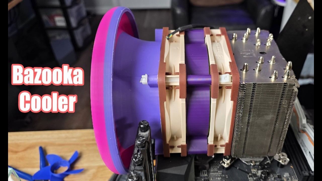
its for radial fans but it manage to be the most efficient at cooling kind of a duct like that im thinking for the front
id love too but i dont understant how to make a curved shape in fusion
so for the intake duct i didn't use my brain too much: i made a loft between a circle and a bigger cicrle in the front: crucial part is to set the inside profile to direction to make it smooth
can you make a v3 with the circular duct not the hex one?
or for this which might be a tad more complex, a sketch with the cross section of it that you revolve along the centerline
v3 has both 😎
and i've setup the project in a way that i can add as many front duct shapes as i want with minimal effort
What color combo would you suggest to base all my mods to the cc from now on? XD

i'm kinda biased on this
hope that this very phallic peg works nice

you could play around in orca with this, just play around with the filament colours, but imo your best odds are to have the hex modifier as a negative or just not at all
too much colour conntrast imo
now this si the peg we deserved
Reminds me of those aboriginal groups in Australia that split the penis down the middle…
my day was better not knowing this. thank you very much
Hey you brought it there first, I just said it out loud 
And could be worse, I could be encouraging further scope creep instead.
if i make the fusion file availble, everyone is repsonnsible for creeping the scope xD not just me
also

same....
so i don't even know what i was thinking with the pegs xD
they are wayyy too flimsy and don't even fit
gonna try this now


Clip_Pegs.gif

i might still prolong the cutout a small bit to reduce the risk of cracking
nice work
rn im at work so i cnat mess with them but i would like to print the new version fo the case too before i need to take the one i have now off
Guess I am gonna wait to print this till yall perfect it 😛
oh comon be part of the trial and error crew XD
peg.gif

printing them out of pla to simulate bad layer adhesion
how should we do this? want me to include it with the other files and credit you, or do you prefer to add it as a remix?
welp testing it out first but i don't see why it shouldnn't work

Oh I don't care it took me <5 minutes to mock up so you don't even need to credit me
Maybe v3 is the one I finally print 😛
https://www.facebook.com/share/r/1FCSyrzS6s/ shipment for v3?
See posts, photos and more on Facebook.
@clever charm any ideea what migth do this or if i can mitigate it somehow?

It started to deform the left air duct
asa?
Yup
well uh shit
Had the same problem with protings skeletonized version i think this one laster more cause more thick
welp ducts are in the same place as stock
i wonder if annnealing it would give it that extra tiny bit of inmproved thermal resistance necessary
Ugh not really in the market for anealing at home 😅
yeah makes sense.. also annealing without fiber reinforcments is a risky endeavour
what is a fix is to use a tz hotend, there is more clearence between the hotend and ducts. my inital petg prototype only has very light warping
Yeah i wanna build the constelation extruder but now kinda scared if it warped like this just being arround it
Also im that stoopid and id need like a list with the links exactly where and what to order
maybe nudge bacon to try to get affiliate links for that stuff xD
@noble mesa Preatty please? 🥺
Id be down to try pc or paht cf even tough it scares me to try them
go for pet-cf 😏
pc is a bitch and paht-cf might creep out of shape pretty quickly
What are the pet cf specs
ok i went ahead and made that more complicated than it ever had to be

uhm good
Led diffuser?
idk what heat resistant clear filament exists tho
that is also not horrible to print
Is there that much heat in that part anyway?
it's a few mm from the buildplate
but under no real load so it might as well not matter
O yeah forgot about buildplate
here it is
White asa thin walls?
Body2.gif

yeah that might diffuse a lot better than clear petg
How did the pegs come out?
really nice. hope that they work well for you too xD
gonna use the clip pegs from now on
Did those make any weight reduction ?
hehe fresh render

yes it is
yep, same duct with improved intake
tho it's only a matter of time until bacon adopts this and they're in cooling performannce
is yours updated with the new airflow design
yeh just uploaded the improved version
great
the cooling ducts after the fan are still identical
i don't dare touch these witout some extensive testing and maybe some cfd before
time to turn on the HEPA filter and run asa cf
yeah i mean why redo the whole duct bacons works pretty well already
Mined too hot
what ABS/ASA do you use
what is it?
i'm pretty sure that it's just the hotend being very close to the duct
The heatbreak fan pushes the hot air directly there and it softens int just enough so that the part cooling fan deforms it with the airflow
Cause its deformed upwards not hanging
that might be due to the internal stresses of the print too maybe?
Idk thats too advanced for me XD
you could set the nozzle to 51 deg and put your finger there to feel for airflow
or maybe 20 i don't quite remember how elegoo setup the heatbreak fan logic
I think the best option for default nozzle would be a specialized duct from the heatbreak intake to exhaust but that defeats the purpose of your design
Il try that but in the morning im too tired to get out of bed now
that's... early
i guess you don't have a daytime working schedule?
Hey i was nightshift and slept 4 hours now i have to wake up in the morning for a 12 hour shift
yeah i think that that's a bit complicated
best of luck
My schedule is dictated by chaos and how higherups mess with the schedule
Il try to feel for airflow in the morning before i leave for work and will tell my findings
Where should i check escaping downwards around the nozzle?
Or just the side?
Understood lets hope @noble mesa gives me a full list of what to get and where so i wont have this problem 😆 where did you get your pieces? Did you also change the gears and the bearing?
@clever charm On the clip pegs for the fan, what are the 2 small triangular pieces
Wedges to lock the clips extended, basically improving mounting rigidity
Ah got it thats what i imagined
PMMA/acrylic, but its not that heat resistant and is kinda horrible to print from what I hear.
oh you only need ASA/ABS for constellation, its less demanding temp wise than the cowling is because its further away from the extruder.
which constellation do you want/what matters to you most?
hmmm i can get some for 30coin/kg
you could also probably cast it in platinum cure silicone pretty easily. its also nice to have around in general. a little bit of talk or something similar would help it diffuse light
I know someone else here was using it, but that was for other reasons™
Beyir?
lol I dont recall who and dont wanna be accused of profiling
I could also remain with my petg until it melts and ruins a multi day print
as is tradition lol
tbh you could go with that clear polycarbonate filament. its probably blended to hell but it will likely be better than petg
and the diffuser would not be a hard print
You mean the pla pc that was shown on here recently?
? never heard of pla pc
Polymaker
PolyLite™ PC: Translucent, Heat Resistant, and Stiff Engineered Polycarbonate for 3D PrintingPolyLite™ PC is crafted from a polycarbonate resin specifically designed for 3D printing, ensuring reliable performance and ease of use. This formulation provides excellent stiffness and heat resistance, making it suitable for
Wasn't there a pc filament that was 70% pla?
oh wait I forgot about that, it wasnt this one.
or you could try pushing the scope creep to 11 and using PEI. you know if you keep it hot enough when printing its translucent

good luck xD i might be safe for quite a while still

hang on a sec, those are really close to the cc's capabilities
i'm gonna stay at pet-cf with improved annnealing for a while
i hope
Nozzle temperature 360 - 390 C -
Max. melt temperature 410 C -
Print bed temperature 160 - 190 C -
**Build chamber temperature 150 - 170 C **
here is a full reccomendation sheet from another manufacturer. its the last one that is the biggest killer
just need to use my chamber ac xD but no no non o i donn't dont need nor want it
my god I need to build a printer that can do PEI so I can have an 10 minute PEI print goin on the same plate a chocolate chip cookie is baking
how would pei fumed cookie taste?
tbh prob wouldnt taste much different
welp i don't know if i will ever make a new duct

hot damn
yeah noped out of that one, luckily they have a youtube series
I have a love hate relationship with ANSYS
if i get stuck on stome stuff can i ping you with it? xD
sure, but ive only used fluent like 5 times
that's 5 more times than i have
Autodesk CFD is enough for me...
well you might be better off looking it up... but i can try...
yeah i'm gonna ingest the whole youtube series to start and then see xD.
good idea. i started off with their youtube as well
welp it's not free :(
or i gotta be fast with it
but i doubt that i will find the time to make an entirely new duct in 1 month given that i've never done anything close to this
how are you getting ANSYS access?
student version
autodesk has student plans too
from what i understand it's basically a home use version like with fusion
and it gets you access to fusion, revit, everything for free
thing is that i'm not currently a student
but ansys doesn't seem to check that
Shh dont let them hear you
ahh i see
Well im thinking sf but the cs sounds good too wich would you recomand? Im not aiming for hf , i want the least parts that gives me the most advantages
And sf sounds like the middle point
ehhhhh I mean I'm partial to HF because it is only $10 more. The only advantage SF gets you over CS is standard V6 nozzles and that doesn't really matter unless you want something specific as the TZ nozzles are pretty fine.
Do you change nozzle sizes ever?
I mean so far i didnt change it from the 0.4 but i like the option
Also no idea what the benefits of the v6 nozzle is
Welp bathroom break over back to sleep 🤣
ECAS04: https://www.aliexpress.us/item/3256808722345135.html
MR84zz:
https://www.aliexpress.us/item/3256808722345135.html can be salvaged from extruder but not reccomended, the abec-5 is better quality than the abec-1 but both are probably at least as good as what elegoo installed
M3 BHCS I think this should have everything but you may need to find one or two shorter ones, just double check the BOM but I think 6-25mm is fine https://www.amazon.com/VGBUY-600pcs-Assortment-Printer-Stainless/dp/B0D1457XQ3
if you do SF or CS you will need to find two short M2.5 screws, this is up to you- maybe steal them from an old computer or buy a set of 20 or something on aliexpress since you only need 2x 4 or 6mm long ones.
TZ3.0 for example (https://www.aliexpress.us/item/3256809118871222.html) I recommend this for SF and HF base. if you do CS you can also use this but the similar TZ4.0 gets you cold nozzle swaps.
If you do SF or HF you will need a V6 nozzle. If you want cheap and good price/performance just buy bimetal (same goes if you need one of the TZ style nozzles with constellation CS if you choose TZ3.0, they have it on the TZ3.0 page as an option. https://www.aliexpress.us/item/3256805883789790.html
If you do HF buy a melt zone extender: This one is what I reccomend as it comes with a silicone sock
https://www.aliexpress.us/item/3256808212338358.html

Valuable M3 Screw Kit:You will get 600pcs M3 x 6mm/8mm/10mm/12mm/16mm/20mm/25mm/30mm hex button head cap screws with matching hex nuts, lock washers and flat washers, it has enough variety to cover all your needs.
10$ more and worse extruder control
Also I lost my mze and it pains me to buy a second one 
you can use standard nozzles you will be able to use down the road on another printer. IMO it makes no sense to buy an expensive nozzle like a $120 diamondback for the CC because its more than likely you will never be able to use it on any other printer. You want to buy a pricy nozzle you want it to be something in a standard format.
It also gives you the option to do moderate priced stuff like solid tungsten carbide nozzles (the best nozzles IMO) for $45.
how do you loose an MZE?
I mean true but thats also true of chube, its just the nature of long melt zones
Idk it kinda just wet to get milk and haven't seen it since
Might have been got by a vaccum cleaner
lol revenge of the cow
lol you would have heard it
will probably turn up, if its the DLC one its dark enough to roll somewhere and not be noticed
Welp idk anymore... Also it's probably at my ex's place so the odds of me getting it back are exactly 0
also who cares about extruder control wen...

exgf or spouse
not sure which is less likely
Reaching 35mm^3/s with stock tz and cht. Wonder what a mze would do
should bump it up to 43-45 prob
Ouch
but at that point you are cooling limited
Do I come across as this old? 
I honestly can't tell how old are you
Not if i got mega super duper ducts
22
oh so gf I am assuming. although I was engaged at your age. ask me how that ended
or bf, or non-gender-specific-f, I don't discriminate
Welp i was smart enough to not add legal stuff to this 🤣
Moving out on Christmas eve was shitty enough
good plan- though you dont get the tax breaks. At least we didnt have any kids
oh damn that sucks. So are you the asshole or are they?
I assume them since you were the one that had to leave
god thats terrible
sorry about that
Oh you can get legally bound without marriage where I live, so you get tax breaks without a lot of the problems that come along with marriage
Dw
I hope that MZE breaks their vacuum...
Probably both, but mainly her parents, which is quite the issue given our age
Dodged a bullet with that one
oh living with parents or just overly involved?
lol other way around for me, my inlaws call me often still, ex never talks to them
Just overly invovled. We had planned to get a shared apartment and they did everything possible to make this not happen... Moved in with my gf and they then threatened me to get a shit job rapidly or they'd kick me out. Given that they have literally nothing to do with any of this I just fucked off
yeah dodged a bullet
Gave me a nice reality check and made me understand that I'd been making quite the amount of bad decisions with my studies
You know what... Ill get a new mze... Screw you
(kindly)
Looks great, fits perfectly. I used the hex modifier as a remover for the front part. And on the back, Printables says to use a M3x12 but I found that the OEM screw fits better


I should've printed with the negative, that looks awesome!
The fuzzy skin makes it look like its metal what filament did you use?
Polymaker Fiberon ASA-CF08 Black, used the orca Polylite ASA profile
Ah cf its not for me then 🙁
why
I have a bad habit of touching my face way to often to be dealing with fibers
Nitrile gloves
exist
I dont have that habit, but i still wear them handling CF or GF because those fibers get imbedded into the skin
Yeah but id prefer not to have to take that risk in the first place, i print im my living room
Ahh okay definitely don't then
relocate that printer, PLA/PETG isn't good either to have in a living space
well other places arent available i dont think the kitchen is better XD
whats the options lol
bedroom living room kitchen bathroom is too cramped already
sorry to keep bugging you with this can you give me a link for the bearings?its the ecas04 link)
wich tz3.0 to get ? on the link there are x1c and p1s , should i go for a kit with fan and different nozzles or bare minimum?(kit comes with m2.5 screws)
should i also get new gears ? i saw in another post someone said neptune are drop in replacements and better (cant remember exactly)
just look up the bearing type on Amazon or Aliexpress
tz3.0 either one works. you’re gonna be using the stock fan anyway and nozzle is up to you
neptune 4 gears are better, they’re a proper bearing with a needle type
correct me if i’m wrong bacon
neptune 4 gears are better and work as a drop in replacement for cc ones.
what gear? the main extruder gear?
from what i can tell they are both exactly the same with the same bearings
https://www.aliexpress.us/item/3256809175647670.html
You always want the X1C option because it has a heater that will work with the CC (or you can just buy the X1C 60W heaters seperately. you reuse the cc thermistor. you also want to reuse the CC fan.
The m2.5 fan screws that come to secure the X1C fan is too long, you neeed them to be shorter than that.
you can buy new gears but don't buy the CC ones, they aren't really better. if you want new gears the best upgrade is the neptune 4 gears which are identical but have a real needle bearing in the tensioner gear and not just a plastic bushing
oh just saw this- yeah this is all accurate
oh that's why i never noticed cause it's hidden
nah, its the tensioner gear- the CC one is just has a plastic sliding bushing
not sure that the neptune isn't a bushing tho
gonna check
and I would generally reccomend TZ3.0 as a safe low cost option for every configuration unless you want to do the absolute cheapest TZ2.0 config- or you want to do the revo-like swaps of TZ4.0 on constellation cs
Are the nozzles that come in the kit with the tz good for the purpose here? I decided to go with the hf after all can just prin another one if i dont like it
The neptune gears i find harden steel and + dlc coating wich would i go for?
Also what are the connecteds on the pcb called? I should get some just in case
i mean, the nozzle that comes with the TZ hotend is good enough
i don’t see any reason to swap it
They’re JST-XH type
what size ? i saw there are different sizes to that too
they are fine, solid steel so a bit lower flow. the bimetal ones are kinda nicer but both are fine
you don't need the DLC coating, I just got the regular steel ones.
are you talking on the thermistor or heater? They are XH on the hotend, I am not sure on the thermistor, much smaller. Just reuse CC thermistor anyway, you'd need a crimper to crimp a new thermistor connector.
first time I've ever seen this used unsarcastically
you can get them pretty cheap I got this one for around $80 shipped but they are always floating around pretty affordably if you search proxeon or easy nlc https://www.ebay.com/itm/254839189906
THK rails not mediocre hiwins, 2x mgn9h linear rails (I think 290 mm or something), one thk dual mgn7c dual carriage rail (110mm maybe?)
also comes with a beefy rear fan one regular stepper, one noncaptive, leadscrews, nice misc hardware, and you get a beefy rear ebmpabst fan with a pelier cooler and 2x CNC machined copper heatsinks for it. Oh and you get a cute little crossflow fan for the rear heatsink

eBay
We will also need to see pictures of the item upon arrival if applicable. If needed, we may need you to send you more information upon request and applied on a case by case basis. We try to the best of our ability to describe the item correctly.
honestly those rails are prob worth $100 considering they move a dozen full cycles each day for a few years max
the LC gradient on these systems is measured in hours
hell you can get a whole easy nlc system for 600 bucks now
why tf is it built like a tank, it's just liquid handling, no?
Oh yeah autosampler also has these tiny integrated lead screw nema 8s for the needle movement on the dual carriage rail.
The other stuff is the rotors and pump blocks on the easy nlc

it probably started life as it is because it was a low volume device at proxeon, then thermo bought them and didnt change anything. they still cnced proxeon into the sides a decade later. Realistically when you are pumping up to 1200 bar the fluidics compenents are expensive enough where overbuilding this part prob doesnt matter as much but I agree its a bit silly. its the most overbuilt autosampler ive seen
whoa, they even threw a 2-piston stirling engine in there :P
And a tungsten carbide sabot round!
Never know when you’ll need antitank support when doing proteomics

average professor / PI office

also tungsten or tungsten carbide?
I believe they used the carbide for this particular size. I was hoping it was depleted uranium but sadly not radioactive
Ah ok i asked cause they the same price as for the plugs i mean all the plugs on the breakout board im scared il brake one, i barrely managed to unplug them when i soldered the led even witth the printed tools
if the thermistor connector daughter board breaks which is really the more likely thing then you have to have to solder it back on. I don't really think replacement connectors will help as it will be just about as bad doing a new one vs old one
@clever charm hear me out this shape for the intake 😆
https://vm.tiktok.com/ZNRPk5DXX/

TikTok
81.7K likes, 1454 comments. “China Launches First Airborn Power Station This idea could really take off 🎈💨”
Only downside is you'd need to leave the top off the CC for the blimp to hover, so you'd be limited while printing engineering filaments 😆
I fking love this coment
There is nothing stopping you 
I dont have the cc by the window to get the blimp that high-up and i think neighbors would steal it
Those are some weaksauce excuses
don't make me ban you. We don't need to go back to the thingiverse special days
back in the day this is what everyone thought peak performance looked like, at least everyone on thingiverse


I think that lots of people still think that that is peak performance by the looks of printables

Only adds 2g!!!!!! Barely makes it worse
The HeroMe, a classic
That's how I mounted and routed the endoscope bte

hey so i might be starting to work on implementing eddy
hehe funny sketch

The goat
@drifting tusk
cover.gif

https://www.printables.com/model/1575497-another-centauri-carbon-toolhead-cover/files test version out now. Anna should have hers printed tomorrow to testfit.

alright, so
this part is too close

on my eddy, that part is 10.2mm wide
other than that, it fits
nice!
can you maybe file it down rq?
yeah, did that with a knife
fits
can't check the height between nozzle and the coil, since I disassembled my toolhead yesterday xd
oh i should get the xy offsets measured too

hm, the Z spacing looks weird
iirc the coil should be 2-3mm above the nozzle tip, but measuring it is like 4.2mm
cad sais 3.8mm. i must have been wayy too tired 🤦
btw thanks for crashtesting this
i think i understand how it happened..... fusion does this funny thing where it sets intial position coordinates to relative at random... so i must have shfited more than planned and not double check afterwards
so that's the probe offsets.

z offset is 2.2mm so that it doesn't need to cut into the toolhead
Now to try to convince biqu to send me a eddy uwu
your face when you discover that the eddy cad doesn't have the switch lever and you need to add a cutout for it

Neato! Just ordered an eddy, figure it'll live in the CC at some point
@clever charm can you adjust the Eddy's Z height to 2.5mm from the nozzle?
also, damn, I only have m3x6mm countersunks at home 😂
is 2.2 really that bad?
the newest version is 2.2mm
that's the current one

yep... that's the reason i am lazy to change it to 2.5mm xD
then it's fine
with those you'll get about 0.2mm of thread engagement xD
or you skip the cover and use m3x4 BHCS. iirc you could steal some from the side panels
petg again?
ye
I have loads of black PETG laying around + it won't go onto my CC anyway because I probably won't have screwholes in the same place and the nozzle will be at a different place as well
oh.. why are you printing it then?
testing?
thanks for the beta testing tho
problem? 
damn i'm not used to people actually doing it xD. i'm used to always pester them and then still end up doing it myself once i recieve the parts 🤣
kinda like sims with the elegoo rfid tags... i bet he would have his answer the fastest if he just bought some new filament
just fyi: the eddy negative doesn't work
why? it's on support blocker by default, you need to set it to negative
yeah i setup the 3mf so that if you don't touch it you get a working normal toolhead
if you want more go get it
makes sense
@clever charm did you print yours in asa simple or fiber infused?
i had to revert mine to the normal one cause if warped too much and made my prints spagety
simple asa. and it didn't move even in a 70C chamber, but i think that the tz hotend gives me more room to not melt the shroud
🙁 fml
I can recommend sirya tech pet-cf. You can get it on Amazon.de for 30€/kg idk what other Amazon locales do
Or constellation
yea constelation is prepared but i wont order it yet cause i wont be home when it arrives XD , also can you link me the parts you used for the gantry upgrades?
if im gonna dissasamble the extruder might aswell do other upgrades too
yeah the gantry needs the whole toolhead to be disassembeled so might as well. If you chose to do pet-cf that would be very cash money of you
and also anneal it
im reluctant of the fiber filled materials already also annealing wont be on my to do list

oh i didnt saw you made a bom with links thanks
i added it just now xD
btw thanks for all the testing you did for this @novel spruce
i just like to be included XD
tbh if i had more experience id test more stuff but some im scared id brake or dont knwo to put back together XD
As i said before, it's already a lot more than i'm used to xD. i remember making a part for a drag chain for someone, just for that dude to ghost me for a really long time. so i just tested it myself once i had access to my printer again
also i often feel bad for making people test stuff for me, cause it's usually a waste of filament

i'm gonna check in the cad if the cooling duct is that much different, but holy shit
well looking at the original ducts i'd like to know what they were smoking now
but i think that they are different enough that you can't really compare the downforce 1:1
wire anemometer would the correct test for this
it has alot of space where they can escape air
welp il probably never gonna have a need for one so i wont be able to test
oh yeah... looking in the cad you can see that... also very abrupt changes in cross section
might be a bit difficult to see, but the gamma duct points a lot more downwards

so anything in short the design was made in paintXD
they probably had their reasons... but the oversized fan and meh cooling performance speak for themselves
some people made a cowling for 5015 fan
5015 4pin tach exists??
isn't that what most bambus use?
i brought this up with bacon a while ago, to his knowledge it doesn’t seem like there is a good replacement for it
i trust i him more than myself 🤣
tbh i don't really see the point of going 5015 over 5020
im really salty about my cowling warping sause iw as thinking of making a white blue one
5015 bambu ones does, but 5020 does not
you sir have made a grave error in judgement
at least you have a PhD
The PhD

i know degrees past a bachelors are useless, but not THAT useless 😂
@drifting tusk did that test ever work out?
yep, fits and looks about right with the Z distance
hey I never said it was useless, its doing a damn fine job of keeping my table from wobbling
sounds like it was worth it
Most bachelor’s are useless in the modern day imo
When 3d printing enthusiats use anything but a 3d printed part to fix something
is this from an official model or the opencentauri cad? because the opencentauri model was made with a lot of guesstimating, especially when it came to complex shapes

GitHub
CAD models of the Centauri Carbon. Contribute to OpenCentauri/cad development by creating an account on GitHub.
official elegoo parts means that the model is from elegoo, or simply that they're modeled after the stock parts vs being optimized for fdm?
literally by elegoo
we asked them if they could provide models for all plastic parts and they literally gave them to us
ooh nice
the gamma duct was designed before we got the official duct cad from elegoo so its def different.
but yeah this is real.
honestly I'm not sure which design is better
tbh this would make a lot of sense as to why the downforce is higher. I wonder what happens with the official duct since the hole is smaller and there is a taper. the gamma duct could be changed
I need to get my hot wire anemometer module running
interesting. just extending the inner anglers of the duct forward lue lines are stock black are gamma. this probably doesnt have too much bearing on actual performance as the angle is going to have limted effects compared to the overall chamber geometry and hole position but its interesting. gamma's internal duct probably also favors more downforce. I also kind of went that route because I was worried some air wasn't clearing the heatblock properly. hot wire anemomemeeter measurement with a mapping gcode macro would be needed.

overhang print test would probably give more applicable results
probably but its a bit subjective which makes things hard. I should do some overhang tests. I did this but like the amount of obstruction on some of those ducts was huge and even then I didnt feel like I could all that accurately tell when warping began https://www.reddit.com/r/elegoo/comments/1lccslf/why_cosmetic_fan_covers_are_a_bad_idea/
I've had a bit of a vendetta against cosmetic toolhead fan covers for while but they have become more common I've a lot of…
I think the ahi default test is a lot more conclusive on that front. Sure it's still not quantifiable, but you don't only want cooling from a part cooling fan but also to not push everything down
wait they have a test?
link pls
Ugh... Gotta find it
I don't even know where to start looking... It's like a spiral flower type of thing
I think it's somewhere in the a4t channel

Thingiverse - Digital Designs for Physical Objects
Neat little test for overhangs. I like to print this at .4-.6 line width, 3 bottom, 0 top, 700mms, 30K acceleration, 20 Jerk/square corner. Print to see how fast you can go before the walls melt. Try 200% model, 700mms, 30K acceleration, 50SCV, and under 6.5 minutes.
awesome thanks!
Thanks for the design @clever charm! Not the best quality print but it'll do. Probably reprint in PET-CF soon

Thinking of reprinting mine out of pet cf too, but I'll wait until my asa one breaks or I finally get around making a new duct
A new duct you say... 👀 perhaps I shan't rush...
Ehhh it's more in pipedream territory than planned. Eitherway there is nothing wrong with using the shroud like it is now if it's in asa or abs
but i yearnnnnn for printing more parts
did you forget to remove the support? 😂 (the hexagons)
The built in support for the top of the toolhead? No, I removed it... though there is a small "lip" left where it broke off? Maybe I should be able to remove more of that?
Oh, I removed the built in supports and then installed the screw in posts for the fan mount
a la these

ah
Still forgot one support, on the top left hexagon there is a contour support to avoid impossible overhangs
hey nozzl3 if you do the new duct i wanna be guiniea pig , mby this time mine wont melt
Will let you know, just keep in mind that it's on the back of the back burner
well im not that advenced or commited to try to make my own so il wait like a good boy XD
@clever charm mby you already know , i just saw in a video the cc2 has a different duct down there

Yep, but no cad and no cc2 makes me completely unable to use it
concept ideea atleast
I'm still no closer to start work on a new duct
🥺
Just really busy rn, so I don't have the time to wrinkle my brain with cfd stuffs for now
did you start work?
LED diffuser beaming. good shit


Yep and other life stuff
how is the job?
Exiting
Exiting your job
Ho Lee, Eddy Duo is way smaller than I expected! So cool
@clever charm refference pic for new intake 🤣

This is merely a threat for the time being, but it goes together nicely

Im too inexperienced does the probe work with default hardware?
It does not
PET-CF hot n ready 🤤

it's calling to me like the damn green goblin mask... but I'll wait for it to come to room temp
Ooo das sexy, got a setup to anneal it too?
I don't 😭 I'm going back and forth on the idea of getting an airfyer or something just for high temp drying and annealing but... haven't committed yet. Just another thing I got find space for
Sous vide works, put it in an airtight bag and them boil it
And maybe weigh it down
Might give that a go
The back bumper hits the left motor when homing, is this because I'm on stock firmware? I know OC homes Y before X to prevent this
I use my wife’s air fryer for drying/annealing… it’s awesome and worth it! Just don’t tell my wife… she used it for the first few days when she got it 5 years ago and hasn’t used it since anyways lol.
I think I'll try and get one of the gourmia air fryers from costco next time I visit - they seem popular for this use
what kind of woman (or human really) gets an air fryer and doesn't use it? I got one for food and have never missed having a microwave since.
Ya not sure… she likes the oven and baking. She can make a handful of pretty nice dishes, always makes cookies and muffins and stuff like that with the kids. She’s a pretty simple girl and I just eat what she puts on my plate lol.
smart man
but they are great fo leftovers
like you wanna reheat those cookies and muffins? air fryer all the way
Dosent it deform in the airfryer? Also what temperature?
the muffins or the 3d prints?
Both would be a good answer but im more interested in the 3d prints
you anneal in a pack bed of salt or some other material
keeps down temperature gradient, provides themal mass, and resists warp
Oh the salt again i tought it was some miracle less salty way 😆
The only stuff I’ve bothered to anneal so far have had 100% infill, so I wasn’t worried about warping and didn’t have any. If I ever need to anneal more delicate parts I will bury them in sand.
warping will still happen with 100% infill, 100% is more essential for if you are doing real salt remelting tho.
but it does strongly depend on part geometry
About 2” wide by 7” long “hefty” cylinder with 100% infill. Part had 250 grams worth of material lol.
oh lol yeah no chance of that warping at all
on oc it would hit the right motor xD. that's what the bumper is for, and i don't think that there is anything one can do so that the bumper doesn't do the homing
Does that happen even on stock cowl? I never noticed
yep. if it weren't for that i might have gone without a bumper
but tbh i think i would have still done it cause of potential layer skips
Interesting, never noticed. Just waiting for klipper release and ill fix that
you can't
or you already can with open centauri if i'm not mistaken
if you home y first, you risk cutting the filament and even skipping some steps
it is fixed on OC
it hits on the right
it's a consequence of homing x before y
it homes y first, then X
huh? in OC 0.3?
iirc it homes x towards positive x and y towards negative y so as to home in the other corner
#patched-fw message
oh shit you are right
huh
makes sense to do it that way, cause you home y while x is at the maximum it will either skip or break something
hey quick question for you about the screws for the side.

they are m3 screws correct?
yes, same ones as stock
because that bottom left screw all 3 times ive printed this toolhead cover seems to crack that piece instantly and make it flush with the the inset .I am using asa and also would there be a way to make it so i could swap them for normal m3x6 or m3x8 screws without the divot on the toolhead cover. i would do it but have no skills in cad design
sorry if thats hard to understand
sounds like that is a cooling issue, or maybe also overtightening. i'll look into if it's possible to use BHCS instead but it might not work since the printer homes there
im not saying its not user error just saying for me for some reason only that bottom left screw hole cracks the small back piece off the back side of it.
curently have the current one held on with 3 screws while i print another one will take a photo of that side once its done to see if maybe it is a cooling issue or if im just to strong for my own good ..
oh it certainly isn't being helped by the design that's for sure, a very thin piece with a screw actively pushing it apart along the weakest axis is far from ideal.
Thats why i was asking about using a m3x6 or m3x8 screw and slightly thickeming up all 4 screw holes

but as you said you dont know if that would interfere with the homing or such
because i have a bunch of these m3x6 & m3x8 and if it doesnt interfere with homing it would be nice to have those thickened up and be able to use those in the pic.
i've got a print to start and then i'll look into it
awesome appreciate it once the new print of your toolhead i got going gets done ill take a photo of that bottom left side to see if maybe its a cooling issue
Same lol mine cracked there too
29mins left on that print of the new shroud
so does that mean you would be able to thicken up the screw spots and make them flat for the m3x6 screws so there is more surface area so it doesnt crack???
yep
currently thinking on how to implementing it without blowing up my file structure

i had to use m3x25 for the toolhead because for me for some reason the the fan screw holders were not deep enough for the stock screws maybe i missed something about that but i actually like how it looks with those screws on the front lol
oh yeah it was designed for M3x6mm screws iirc
the stock fan screws don't get reused
ahh i missed that then lol
just verified the documentation, it's
screw in the fan with 2 M3x6mm BHCS, DO NOT OVERTIGHTEN IT. The pegs and printed threads are quite weak so it doesn't take much. If you break one you can just replace it.
also that's quiite a funny picure
toolhead printing itself
is there a way to make an edit to the front hexes to remove them and add a small bump to allow m3x30 screws to hold the fan in with a nut on the backside??
if i knew how todo cad design id just do it myself
im trying to learn fusion but man a steep learning curve
not really, the duct design relies on being able to slide the fan in from the top. doing this would make it a lot more difficult to insert it

that looks really crisp
that back piece to that screw hole is what keeps snapping

thats how it keeps cracking for me on that left bottom side
huh that's weird. does it line up when you place it on the carriage?
i'd hope that the cad that elegoo literally sent is accurate
yes lines up perfectly
hmmm what cooling settings and filament are you using? i suspect that the default asa profile completely overcools it for short layers... which makes layers not able to withstand forces like these
i've only managed to break those once by forgetting half the screws and ripping around on the toolhead
my modifiers are as ugly as always xD

Polymaker ASA and these cooling settings

my nozzle temp is 275 and chambers temps sit around 35-45c without a chamber heater i have the small heater setup just waiting on the magnets to mount it so i can get higher temps in the chamber
and yes ive tried lower nozzle temps for asa and prints seem to get worse 275 seems like the sweet spot on my printer for asa
huh.... well at that point i doubt that layer adhesion is an issue

the fusion file looks more and more fucked xD

i mean that happens when you get hella deep into how it mounts
this is mostly a lot of overlapping modifiers and support
ahhh also i was wondering how and eddy would work on this printer without the full swap of mainboard ?
im assuming the mainboard swap was done and thats why there is an eddy option for your cover
i do love the design just hate how they have the screw mounts on the tololhead mount
the ones at the side for the carriage?
yea
it works really well with the constraints of the stock cowling but for this one it's kinda meh
but short from mounting directly to the extruder this is the best solution imo
yea that makes sense
@lilac zodiac @tight ibex just delete the countersunk screw modifier and you're good
Front_Cowling.gif

printables is updated
nice appreciate it
that should solve any issue with cracking for sure on those screw holes
if it cracks now then ill know ive put too much tightening force on that area
Oddly enough I had to shave down the ring near the fan as it was preventing the fan from spinning. But she works now 🙂


Will print a better one later in asa
did this one in abs
How would one go about removing the slight indent on the holes i believe that slight curve inwards is whats causing me the headaches which is why i asked about a flat surface one for m3 screws i mentioned idk if i grabbed the wrong file or what?


nvm figured it out i was being a derp lol
does the 3mf file come with the print settings like layer height, wall generator etc?
It doesn't i've had issues with orca crashing with certain settings so I didn't touch it
when printing this, did you change any cooling settings? I’m trying to print it in ASA-CF and i’m having some trouble with droopy bridges, mainly around the fan duct support
those are the settings i used
do you have a picture of the issue?

I'll get a pic when I get home, but I'm sending another print with those values now. This is what I had before:

also i should add that my settings are in a 65c chamber at 30mm^3/s
1st, 2nd and 3rd attempts
no changes between 1st and 2nd
chamber @ 55 degrees, not sure what’s the speed though, and i’m always confused when people mention speed

Hmm looks like I should reduce the bottom support distance...
try this profile for your asa-cf i use it with all my asa-cf filaments
@clever charm i need some help idk i changed or what i did but im still using your asa profile and man its giving me a headache


increase your z offset
Any idea what can cause this ? I think im using the newest orca dev
Well thats the thing i did increase it and it started to separate also all top surfaces look like that not just first layer
also your flow ratio might be different than mine, i have it tuned for my setup. it can vary with yours

With the flow calibration from orca?
oh wait yeah one of the pictures is you tuning the flow ratio
woops
but everything i see in the first 4 images is z offset too low
hard to tell if there is something else going on too but that's the main one
oh and i removed the 0.98 flow ratio from my profile too
so that might explain stuff
Im at 0.110 at 0.120 it separates...
What does that mean ?😅
Any chance this migth be a partial clog?
i wouldn't say so, but it's easy enough to check. extrude in mid air and see what happends, after it stabilizes you should get the filament going straight down
Well it not a clog ... I did a z offset of 0.26 and weirdly enough its the same result now
The straigth extrusion has small bumps sometimes

Thx for the z offset thing but the problem is that it worked before
@clever charm any toughts on this?
from what i understand the cc has a unreliable z offset issue. and also different plates can have different thicknesses that throw this off. since the homing isn't done with the nozzle it actually matters
i dried it for 8 hours 60 c
Z offset being too low. Upward bucking orthogonal to direction of lines is diagnostic
Also the bed warps when you go to ASA temps, yours prob bows upward thus the z offset issue
i understand that but why the sudden change it worked normaly
thx! i gave it a look and it’s based off the same profile I was using, so I just calibrated my filament on top of it
Can always smooth the ASA with acetone
problem is that while its printing it hits the bumps it creates and dont wanna bend the nozzle
I usually heat soak my chamber to the temp it will be while printing the ASA, then do my bed level right before print.
This is how my Asa came out for the idler blocks I made just using generic asa settings


Idk anymore not even the petg cooperates anymore

Same gcode as last one now looks ok idk what to think anymore
my nozzle is clogging and im elegooning so hard right now 10/10

My nozzle is unclogged now, you don’t have to worry
But my nozzle did really clog several times when testing out different colors for the hex part, I was extremely lazy switching from ASA to PLA
Very interested to see how the pla i used for color will hold up, if anything happens at all that is
Yeah that's a ballsy move you did there, but great idea
Kinda happened on accident first time, was gonna do some testing with purely ASA but forgot the white spool I was going to use to test flow rates for the hex pattern was pla and not ASA
does the difuser work with stock cowling? also what material to print it in?
no, the underside isnt exposed
(at least I don't think it is)
and clear petg might work but clear pc would be better
how is the tut for constelation going ?XD
oh uhhh... still sidetracked sorry
soon™
tbh I'm prob just gonna do a video on assembly first instead of the full cad docs because I need to remake mine after revising
rn i dont have disposable income to order the parts cause i wanna do the cloggedz idlers too and kinda expensive it got
can i find the bambu screw on ali ?
maybe, but you don't really need it. the TZ hotends come with m3 shoulder screws, they are not as tight as real bambu ones but they work fine and if you have kapton you can put a layer aound them and that could help
Looks good, but you need to be extremely carefull if you use filaments with cf
Carbon fiber is conductive, and can potentially burn the Btt eddy, as it is so exposed
That’s why on my version I made a small cover, and on the bottom of the eddy I have placed kapton


I was under the impression composites are nonconductive because the particles are mostly idolated in polymer from each other
would anyone be interested in having a bambu 5015 version?
at looking for bambu seems to be the cheapest option
also looking for this fan, i notice how similar the design language is xD, it was not on purpose xD
oh yes please !
5015 nozzle or fan?
how can one survive without drinking
intravenous beer
Could one fit a 6010 
12070 ... that would be great. Com on Guys .... this fucking 5020 from elegoo ...
I haven't found anywhere yet where I can buy a replacement. Elegoo itself is charging €16 for it, plus shipping.
i mean their fan is quite powerful
is that power even needed?
making that better geometry is not trivial though
just knowing if it's even better is already quite the task
only real good thing is wire anemometer or actual test prints
could do some silmulations aswell but bruh
does non premium fusion support that?
nope
20€ for such a fan????
no ... 4pin by elegoo ...
but with cosmos ...
Nah... just the speedometer signal. So, the RPM. But we're not interested in that anymore.
that was already not an issue with stock
just gives you an annoying warning and that's it
but the pins are Vcc gnd pwm and tach
and I even hated the warning
but does it give voltage when you use a non pwm fan
yeah 24v at all times 🤣
i can testify, not good for getting a first layer to stick
Isn't there a triac on the output there? ... In that case, VCC and GND would be sufficient
I'll definitely have to give it a try once the print is done....
is your model fan broken?
there is more broken at the moment ggg
good luck man
mine is xD
Kids are doing science projects :D... and I'm NOT taking any pictures of my CC1 as it is right now
whyy
Loose cables, weird things stuck to the sides, and more. I don't want to be to blame if someone tries to copy this. 😄
if i show you my cc will you share it?
help a random weeb appeard
public execution 8pm
FINALLY!
no 😄

i much more prefer gravity powered methods

hey it has charcter
it's boaring 😄
and it only does 10k accel in the x axis according to inputshaper
you mean the same character as a rattlesnake?
and 5k in the y
that's really decent for the cc
that not so much
but with all my mods I barely get any imrpovments
where can i see the graph
export the csv and run it through another klipper machine
or install klipper on your pc and run it there
i have a another killper host wait
where is the csv tho
## [input_shaper]
## shaper_type_x = mzv
## shaper_freq_x = 54.0
## shaper_type_y = zv
#*# shaper_freq_y = 44.6
/tmp
there are 4 files
should be shaper calibrate and axis and some numbers

should i see if i can make it work with a custom carriage to further increase stiffness and reduce weight or keep it as is?
i think a basic alu profile with a chinese mgn12 would wonders
at that point just make a whole gantry
i mean
yea
wait i have to export my csv
not anytime soon, don't got the money or time to sink into useless shit
idk if i will even do a cowling at this point or just let the ducts duct around

very rough still

With great power comes great... heat, apparently.
Mistakes were made, V2 will be unmatched.
PCBWay's services made this possible, check them out!
https://pcbway.com/g/2EZ6k2
BenQ ideaCam product page: https://bit.ly/3LMJh0F
Amazon product page (US): https://www.amazon.com/BenQ-ideaCam-Plus-Resolution-Microphone/dp/B0BPB6L5R8
Music ►► http...
1000 likes and i put this in my elegoo
is that the lost cause newzealand guy?
he has a friend call mitsu builds
he makes the same stuff but less often

mitsumakes
sorry
bad with names
oh yeah i've been following his wood angel build
never seen a ssr for an nozzle heater

piggi snout

it smells trüffel
it can smell my pain

what?
or give them a flat front so that they can print
oh no, i did dumdum
@noble mesa any feedback on the shape of those 🦆
aiming for a really low restriction design, but it's my first time really designing a duct so it's very guessworky
hmmm
why not make em wider
static pressure?
and why spilt them in two channels ?
im not asking to questionig the design rather to find out why btw
from what i understand it's the most efficient cooling method
feel free to question me, this is in part a learning exercice for me, so attacking my assumptions is good thing
they arleady extend basically as wide as they can fit
im clueless when it comes to fluiddynamics (is that even the right thing?)

yep that's the right thing
hmm why are they asymetric?
depends on how sharp it is
cause the flow is as well, outside of the fan is moving much faster than inside, so it's to have about the same flow going to both sids. though this is a total guess as to where the split should happen
this shows it pretty well

i removed that now and plan to add it later, but it's basically so that the air can't as easily stack up at the outside of the bend
which in this case would cool behind the nozzle
so is a turbolent flow better for 3d printing?
sorry for asking these strömungsmechanik 1 questions
lol
no clue, not even sure if we can get somewhat laminar flow. But i think in general slightly turbulent flow is ideal
too turbulent and you loose a lot of energy to the turbulence itself
btw this is just guestimating.... in fluid dynamics i never got furhter than bernuli and newtonian considerations
that's bascially me with uni.... even tho i'm interested in the subject manner i just can't
i mean its all very intresting but the stress
i just cant
oh for me it's the boredom of going to class for 2h when you could learn all of that really efficiently
i loved it when i had leassons at 13:00 and 3 hours nothing until the next leasson
pretty fast after that i stopped going
ok i think this is the smoothest i'm gonna get them for now

also should do a fluid sim before trying to change the shape any more
cause they are already a pita to get to work with fusion xD
i guess somethings never change with cad
i wouldn't exclude a skill issue. but nothing has made me doubt my cad skills unlike those ducts
curretnt very blocky looks

anycubic called

at least you don't say it's a fucking truck cab
creality toolhead when

that's the SE3D no thank you

shots fired at the goat
or what would be the creality style?
I gotta say, the K2 toolhead looks pretty
random bullshit

goat as in he makes annoying noises and shits everywhere?
yeah aint gonna happen without major rework of the whole toolhead xD
remixing his 5020 toolhead rn
I mean, and it needs a linear rail 
kinda reminds me of a portal turret
reminds me of GLaDOS
not really remixing as in making a completely new one from scratch

lgtm
is that a lamp shade?
should put an old heater cartridge in the bottom
prusa called
heater cartriges are still the highest performance option as of today
at least to my knowledge
no
well
highest temp
but slowest heating rate
i mean like power at high temp

possibly too yeah
yep. just gimme full brr
let heat transfer limit the max temp
which ones resistance increases with higher temp
PTC / MCH / whatever you wanna call "silicon heater pads"

technically (almost) all resistors increase in resistance with higher temp
just MCH / PTC a lot faster cuz their wires are so much thinner
source: I made it up
hehe ntc heater
❤️
what could go wrong
instant runaway
means heating up faster tho 
just as my grandma used to say:
going without protection doesn't necessarily make it faster
faster to get pregnant
and the 3d print is the child
perfect analogy
absolutely
anal ehehe
ew

ok coming back on topic, this screw hole should be alot more solid now


ok ill stop bashing i couldnt design this
nah feel free fr
and if i would it would be a messy workspace
mine isn't that clean either

you make folders?
ez project


random bullshit numbers
idk what is what
maybe should, renaming the sketches would already help
yeah fusion timeline helps with that xD
and the worst part is that i can quickly orient myself in the mess
i don't understand that attitude tbh. as long as it's not a complete clusterfuck whatever
what counts is that you get the file done
i wanted to share my workspace with atom
and yea
its like having a visitor
and cleaning your room yk


still looks kinda shit, but slowly getting it to a less shit look

what i love about this fan is that it's not gonna need pegs at all
so it'll just screw in and not be a headache
it looks sleek
welp that's gonna need some help

front bottom got a necessary facelift

yeah those ducts still need huge improvements in general
f
those fucking ducts are gonna be the end of me
You can do it ❤️
i'm struggling
i want the duct to be horizontal in one part before bending
and i can't get it to be horitzontal, smooth and not error out
I wish I could help but um, today my struggle was modifying a step file to make some magnet holes bigger and add some extra magnet holes... we are not the same 😅
when searching youtube for info i stumble upon this :( https://www.youtube.com/shorts/a1XiMWe0mAk

Call/WhatsApp +919700147335
"Hire us for your product design"
Instead of creating 3D sketch (not robust) try creating the edges with extrude for pipe/chassis to create robust easy to edit model.
This method is proposed by TheCADWhisperer in fusion forums
forums.autodesk.com/t5/fusion-design-validate-document/workflow-guidance-for-designing-pi...
seems like loft is not the appropriate tool for this
having some serious doubts about the form tool being appropriate either

skill issue time

this sort of design is beyond me lol.
you and me both xD... gonna go to bed and watch some tutorials. maybe i'll wrinkle my brain in my sleep
honestly its probably the right way to design the duct for this but I have trouble working this way, I need to cut ducts out of cross section shell them, and then smooth like i did for the aux fan. directly forming a profile from a cross section along a path is hard
using the form tool is, right?
fuck if I know, what software is this
for now my plan is to skip the shell operation by using the full ducts as tools to cut out of the body of the fan. it's way too unreliable otherwise
fusion360
oh didn't recognize it because of the different environment
yeah I have no idea. I'm only really familiar with the solid tools and I'm guessing these are surface tools
yep, i think those bends are just too complex and tight for a loft to work well. end up lacking a lot of control. only last solution i'd see is to have 4 guide rails which are all carefully planned out
yeah I expect a loft operation to fail and prob not be the best approach
it miraculously worked ok ish, but not ideal for printing
https://cdn.discordapp.com/attachments/1466083137967755356/1492647196384952443/image.png?ex=69dd6907&is=69dc1787&hm=cb09bebe70ac78c27e67a03fbfa171eff514d31679458806760917ff14655c01&
https://cdn.discordapp.com/attachments/1466083137967755356/1492685416040759306/image.png?ex=69dce3df&is=69db925f&hm=4e4dae75fba2d33c5e9b53a7d5dfa9a3b6cf9441180bf0331802d068c75b6cce&
@noble mesa those were done using the loft tool


fun! my inclination would have been to split the duct further down but I think this will work well. You might be able to to get it more printing optimized by adding a one layer strut/bridge on that overhang region so the plastic has something to hang onto as you do the steep angle. or you just cut a bit out flat so its straight bridging
2 wall 20% infill 💀
@noble mesa would you by chance have an accurate model of the bambulab 5015 fan? rn i'm using https://grabcad.com/library/artillery-x4-pro-radial-fan-5015-1. which looks good apart from the fan blades
I modelled one with wide mouth but I'm not sure how perfect it is hold on
DB5015B24M-P.gif

Yeah, if possible, I think that including some trunk distance below the fan, before the split (to allow the output pressure normalizing) makes the splitting of the flow a simpler proposition, also gives a beefier unified structure (stronger outright, and per gram) before splitting into smaller structures at the necessary point
ok i will have it merged for longer, as for the structure, i will still have an outer cowling so it doesn't really matter that much
this looks so goofy
