#enfusion_model
1 messages · Page 28 of 1
 brisk grotto
 fickle vigil
brisk grotto
BSP and box volumes are shown on the wiki for FBX import. Think theres also a vi...
fickle vigil
brisk grotto
BSP and box volumes are shown on the wiki for FBX import. Think theres also a vi...
Both the wiki and the videos I’ve found are perfect squares and only like 2 rooms max. I’m working on 20+ story buildings with varying room shapes and sizes. I’m just having trouble visualizing what BSP should look like for those buildings
brisk grotto
fickle vigil
Both the wiki and the videos I’ve found are perfect squares and only like 2 room...
BSP principal remains the same, simple geometry that boxes off your walls, floors, roofs etc that you want to contain light, sound etc in. Use cutters for doorways,
Windows etc you will portal layer.‘I’m fairly sure there’s a couple multi-story base game buildings with BSP
fickle vigil
brisk grotto
BSP principal remains the same, simple geometry that boxes off your walls, floor...
Do you know if the entire bsp need to be one connected, continuous mesh? Can there be boxes which are not connected to any other bsp boxes? The wiki only shows a single story bsp so I’m not sure if each level is separate
Only way I know to view bsp geo on assets in game is via diag menu but it’s nearly impossible to see it well
brisk grotto
fickle vigil
Do you know if the entire bsp need to be one connected, continuous mesh? Can the...
Naming is BSP_xxx where xxx is some convenience name, there can be many of these as separate geometry which will be merged together
This is on the wiki
they can be seperate geo but the engine will merge them together
 distant urchin
hey im currently working on gettings a 3d model to be driveable i have been watching argh's videos about it but im really struggling on the bone section in blender i have the AR vechiles addon installed in blender but what i tried before messed my model so bad the workbench kept spamming error popups any chance anyone can walk me through the bone/armature part?(yes im very inexperienced with blender/arma modding especially blender)

 remote palm
There are samples on github, and also a car. You can download those samples and import them to blender. That will probably help you the most 🙂
 eager ruin
remote palm
There are samples on github, and also a car. You can download those samples and ...
eager ruin
remote palm
There are samples on github, and also a car. You can download those samples and ...
100% the way I've learned everything in the Enfusion pipeline. Have a concept, see a few things that are similar or at least use a translatable thing, disassemble, reassemble, attempt to assemble mine.
This is how I made my Huey bomb racks, they're underpinned by WCS_Armaments, but I looked at their Fab bomb, saw how that worked, then looked at their rocket pods and saw how those worked, then I combined the two with my rack of mini bombs(mortar shells) and now I have a Huey that can carpet bomb.
fickle vigil
brisk grotto
`Naming is BSP_xxx where xxx is some convenience name, there can be many of thes...
thank you for taking the time to help me on this btw. Really appreciate it
 sage lance
How do you all properly address poor shading/reflections that occur when using the decimate modifier to create LODS? I’ve always had this issue, which I thought I recently resolved by using shade auto smooth to 180 and smooth angle to 30. Turns out that, while it resolved it, it was resulting in terrible vertex/face counts. So now I’m trying to figure out the proper way to go about this
 raw tundra
sage lance
How do you all properly address poor shading/reflections that occur when using t...
raw tundra
sage lance
How do you all properly address poor shading/reflections that occur when using t...
I only run into issues when I'm decimating too aggressively or when my topology is a bit of a mess to begin with. Here's an example of one of my models, although not a great example because it's already fairly low poly. Each LOD, beyond LOD0, has a decimate modifier using edge collapse where the ratio is reduced by almost exactly half each time (LOD1 = ratio .5, LOD2 = ratio .25, LOD3 = ratio .125, LOD4 = .0887).
I would try to stick to reducing face count by only about half with each decimation, and if it's still too aggressive you should evaluate if it'd be more appropriate to bake your high poly mesh to a low poly mesh before creating your LODs, or even clean up the base mesh's topology a bit.
 remote palm
sage lance
How do you all properly address poor shading/reflections that occur when using t...
remote palm
sage lance
How do you all properly address poor shading/reflections that occur when using t...
I dont decimate. I have my LP quad model and remove edges manually. That way you have full control.
Helmet is purple since i dont have the assigned textures on my MBP
I could go even lower with the first LODs, but its close enough to vanilla.


 sage lance
raw tundra
I only run into issues when I'm decimating too aggressively or when my topology ...
sage lance
raw tundra
I only run into issues when I'm decimating too aggressively or when my topology ...
See, the issue w/ me is that my models tend to be large vehicles, trailers, and train cars, so the messed up reflections/shading is much more noticeable when switching from LOD0 to LOD1
sage lance
remote palm
I dont decimate. I have my LP quad model and remove edges manually. That way you...
I will have to look into the viability of this for my models. This may be possible for some of the ones with few parts, but I’m assuming this would be hell to implement on most of them considering that they possess hundreds (sometimes over a thousand) loose parts
raw tundra
Yeah, since LOD0, LOD1 and maybe LOD2 will be the most used LODs and your object has fairly complex topology, you should be more gentle on those LODs and save the aggressive face count reduction for the later LODs. Unfortunately, as you probably already know, there's no one-size-fits-all solution when it comes to complex objects and some of the ugliness is unavoidable.
Honestly, if the main area of concern is the ugliness from LOD0 to LOD1 you should try to add more LODs and be very gentle in that transition.
Hopefully some of what I said helps 🥲
sage lance
raw tundra
Yeah, since LOD0, LOD1 and maybe LOD2 will be the most used LODs and your object...
That was actually one of things that I was initially doing. I would not decimate any flat walls/panels or smooth body sections for the first few LODs, and just focus on the small parts. Problem was that it didn’t always result in the vertex reduction in LOD1/2 that I had hoped, but maybe that’s not a big problem
raw tundra
sage lance
That was actually one of things that I was initially doing. I would not decimate...
Yeah it's not as big of an issue as you think, as those kicks in when you're fairly close; I want to say within ~30meters. For context, the UAZ452 Ambulance starts off at 191,475 faces and is only at 5764 on LOD4, so if you can manage similar numbers while maintaining your personal preference for visuals, then there isn't anything for anyone to complain about.
With vehicles it's easy enough to destroy all of the internal faces when creating later LODs, because they will never be seen by the onlookers anyway  so if you did want to manually reduce face count, that'd be a good place to start.
 austere jewel
Guys quick Question:
- Whats the recommended poly limit that you should not go over (for a single model)
- And how many LOD's should i make for big static Models like an Aircraft carrier?
brisk grotto
austere jewel
Guys quick Question:
- Whats the recommended poly limit that you should not go o...
It depends on the type of object, alwys best to view an equivalent base game xob to see the LODs and poly count
 wicked dirge
sage lance
How do you all properly address poor shading/reflections that occur when using t...
wicked dirge
sage lance
How do you all properly address poor shading/reflections that occur when using t...
you should manually go over it and reapply appropriate hard edges
 shell hedge
Well, there are a lot of different LOD tools, if there is a lot of points in very close vicinity then C4D's reduction algorithm is great, but at some point the process goes manual for me almost every time
 compact scarab
austere jewel
Guys quick Question:
- Whats the recommended poly limit that you should not go o...
compact scarab
austere jewel
Guys quick Question:
- Whats the recommended poly limit that you should not go o...
Aircraft carrier depends on the complexity but you could prob go up to like 400k. And i'd do 5+ lod's prob for something that size.
austere jewel
Im slicing the model in multiple parts anyway
 fallow pond
why?
 faint viper
compact scarab
Aircraft carrier depends on the complexity but you could prob go up to like 400k...
faint viper
compact scarab
Aircraft carrier depends on the complexity but you could prob go up to like 400k...
i had some of my models for some big spaceships, and they go around 300/400k easly without any issues on performances, i always think about whats the player impact on that, is it something from distance? something that people can walk in, that helps a little bit to know how much do you wanna give it and as last probably you will just keep 1 of this, i doubt you will have 10 aircraft carriers
 glossy prairie
Hello. I'm making a Grenade Launcher, and I also made my own grenade for the weapon, but when the weapon fires, it doesn't explode and doesn't deal damage. Why might that be?
raw tundra
glossy prairie
Hello. I'm making a Grenade Launcher, and I also made my own grenade for the wea...
How did you go about creating the grenade entity? Did you inherit from an existing one?
glossy prairie
raw tundra
How did you go about creating the grenade entity? Did you inherit from an existi...
Yes. I got the Grenade Launcher in Arma Reforger.
 sly bridge
fallow pond
thats not unreasonable for dx12 game
sly bridge
fallow pond
thats not unreasonable for dx12 game
xbox s might wanna have a word with you on that matter....
raw tundra
Can you maybe post an image of the grenade and launcher's object properties/component list? Kinda like this. If you didn't inherit directly from something that already exists in the engine, then you may be missing a component, and if you did it may be that the components just aren't configured properly. Either way, a picture would help me help you
 glossy prairie
raw tundra
Can you maybe post an image of the grenade and launcher's object properties/comp...
glossy prairie
raw tundra
Can you maybe post an image of the grenade and launcher's object properties/comp...
There are no SCRs. We're adding these to the launcher, not the ammo, right?
 glossy prairie
raw tundra
https://tenor.com/view/photo-camera-man-taking-picture-gif-12506814772408339608
glossy prairie
raw tundra
https://tenor.com/view/photo-camera-man-taking-picture-gif-12506814772408339608


This magazine

And ammo
 raw tundra
Okay, and it's firing successfully, it just doesn't actually explode?
glossy prairie
raw tundra
Okay, and it's firing successfully, it just doesn't actually explode?
Yes
glossy prairie
raw tundra
Okay, and it's firing successfully, it just doesn't actually explode?
The weapon fires, but the explosion effect and NPC damage are not working
raw tundra
glossy prairie
The weapon fires, but the explosion effect and NPC damage are not working
What are you using as a warhead in the CollisionTriggerComponent?
faint viper
Questions for mods/BI, how much is gore allowed into the game? I want to create a set of dead characters with missing parts and stuffs is it ok or nah? Thanks
glossy prairie
raw tundra
What are you using as a warhead in the CollisionTriggerComponent?
M433 effect
raw tundra
glossy prairie
M433 effect
It's this one?
 glossy prairie
 sly bridge
faint viper
Questions for mods/BI, how much is gore allowed into the game? I want to create ...
sly bridge
faint viper
Questions for mods/BI, how much is gore allowed into the game? I want to create ...
@delicate condor
faint viper
Thanks, wasn’t sure about tagging
 delicate condor
faint viper
Thanks, wasn’t sure about tagging
delicate condor
faint viper
Thanks, wasn’t sure about tagging
no gore. The dead bodies in the game are as far as you can go
faint viper
delicate condor
no gore. The dead bodies in the game are as far as you can go
Ok thanks. So just lot of blood but no mutilations
delicate condor
faint viper
Ok thanks. So just lot of blood but no mutilations
not that much blood
faint viper
delicate condor
not that much blood

delicate condor
please dont try to test the limits
faint viper
delicate condor
please dont try to test the limits
I see, so wondering since we already are talking about this, if it’s a creature that misses like an arm, but I don’t texture it gore hard oriented is it fine? At least I know to not create something like that in the future, because I had a model with a missing arm and an other that crawls without legs but with texture I can make it ok and not too gore.
delicate condor
Horror elements are difficult ratings wise and not especially intended in the game so you can DM me pictures of those
faint viper
delicate condor
Horror elements are difficult ratings wise and not especially intended in the ga...
Okk thanks, once I’m done with them and home I’ll send pics
fickle vigil
austere jewel
Guys quick Question:
- Whats the recommended poly limit that you should not go o...
I have a GM placeable model thats 1 million vertices/ 1.3 million faces. I can slap it down in a congested area of players without issue lol. You just need to figure out what poly count is worth the fps drop. I usually try to make 6 LODs but some models become ~100 poly before LOD5 so I might stop there unless its something that will exist in large quantities
austere jewel
fickle vigil
I have a GM placeable model thats 1 million vertices/ 1.3 million faces. I can s...
oh interesting! good to know^^
compact scarab
delicate condor
please dont try to test the limits
Can we push the limits of the engine?
delicate condor
compact scarab
Can we push the limits of the engine?
well if you end up breaking stuff that wont be good either. But I was talking about the limits of the rules.
compact scarab
delicate condor
well if you end up breaking stuff that wont be good either. But I was talking ab...
Haha cool yeah i know. I should have put a wink emoji. I'm definitely gonna push the physics to its limit, though.
glossy prairie
Why can't I put the weapon in the slot? Where should I check?

 topaz willow
glossy prairie
Why can't I put the weapon in the slot? Where should I check?
topaz willow
glossy prairie
Why can't I put the weapon in the slot? Where should I check?
check the WeaponComponent and which slot it's set to: primary, secondary, or grenade
glossy prairie
topaz willow
check the WeaponComponent and which slot it's set to: primary, secondary, or gre...
It doesn't work when I select the Weapons tab either.
 topaz willow
glossy prairie
It doesn't work when I select the Weapons tab either.
topaz willow
glossy prairie
It doesn't work when I select the Weapons tab either.
not that, there's a specific slot for setting which quickslot it goes into
I'd show but game is updating at the moment
glossy prairie
topaz willow
I'd show but game is updating at the moment
I'd appreciate it if you could help me when it's updated
topaz willow
glossy prairie
I'd appreciate it if you could help me when it's updated
weapon slot type
 glossy prairie
topaz willow
weapon slot type
glossy prairie
topaz willow
weapon slot type
Thank you so much, I've been looking for this for hours.
glossy prairie
topaz willow
weapon slot type
Thank you very much
topaz willow
if all else fails, can always copy from a vanilla weapon and work backwards 
 tepid cloak

 brisk grotto
tepid cloak
brisk grotto
tepid cloak
Nice, if I can make a suggestion I’d advise making the patch an actual mesh in it, it looks too flat
remote palm
True. Watch the patch guide from RHS it was i think. They did a great one
 surreal ore
Completely uncalled for. No need for an extra mesh when a good normal map will suffice.
brisk grotto
surreal ore
Completely uncalled for. No need for an extra mesh when a good normal map will ...
It may be personal preference but I just think even with a normal map it will look too flat, and a mesh for a patch wouldn't be very significant verts wise
surreal ore
brisk grotto
It may be personal preference but I just think even with a normal map it will lo...
But there is no need. No one is gonna be close enough for that to even matter.
Normals exist to keep from having 3d geometry when it's unnecessary.
fallow pond
even in A3 the patches were meshes / decals
tepid cloak
I started a healthy discussion lol I have made a separate version, uv on hat VS separate model


 fallow pond
better to have as a separate model since its more flexible. having it part of the texture is like old school stalker half life 1 style.
raw tundra
tepid cloak
I started a healthy discussion lol I have made a separate version, uv on hat VS ...
The first one looks much better 🫡 (IMO)
 fading cloak
tepid cloak
I started a healthy discussion lol I have made a separate version, uv on hat VS ...
fading cloak
tepid cloak
I started a healthy discussion lol I have made a separate version, uv on hat VS ...
you doing these ones for me hahahaha and no not a joke
one of my friends asked you for these 🙂
 chrome crater
Working on some boots. Im totally new to enfusion modding.
At the moment im stuck at the Configs stuff... i dont get it why i cant put my US entitycatalog into my Campaignfactionmanager... So im not able to put the boots in the arsenal -.-

 fading cloak
chrome crater
Working on some boots. Im totally new to enfusion modding.
At the moment im stu...
fading cloak
chrome crater
Working on some boots. Im totally new to enfusion modding.
At the moment im stu...
as someone that plays recon in milsims love these
tepid cloak
fading cloak
you doing these ones for me hahahaha and no not a joke
maybe I am 🙂
tepid cloak
chrome crater
Working on some boots. Im totally new to enfusion modding.
At the moment im stu...
tidy shit
chrome crater
May i have a little Problem. i dont know why, bit in my selfmade szenario i can the boots. but as soon as i Hosta private or go via Arma as GM in game i cant find them in the arsenal. Any hint what i do wrong?
 pine cosmos
chrome crater
May i have a little Problem. i dont know why, bit in my selfmade szenario i can ...
pine cosmos
chrome crater
May i have a little Problem. i dont know why, bit in my selfmade szenario i can ...
Do you use other mods for the arsenal or other stuff? Like wcs that overwrites the arsenal config?
You might have to add your boots to the factions arsenal
Its a script portion
chrome crater
No but i already solved my Problem. i just duplicated the entidyconfigs. i didnt set the to override. Now its override and u can use it in the arsenal. i already published the Mod to the workshop! 😄
tepid cloak
ended up redoing it nb for a 200kb model 🙂


Watch "Desktop 2026.02.01 - 20.45.49.01" on Streamable.
 hoary gazelle
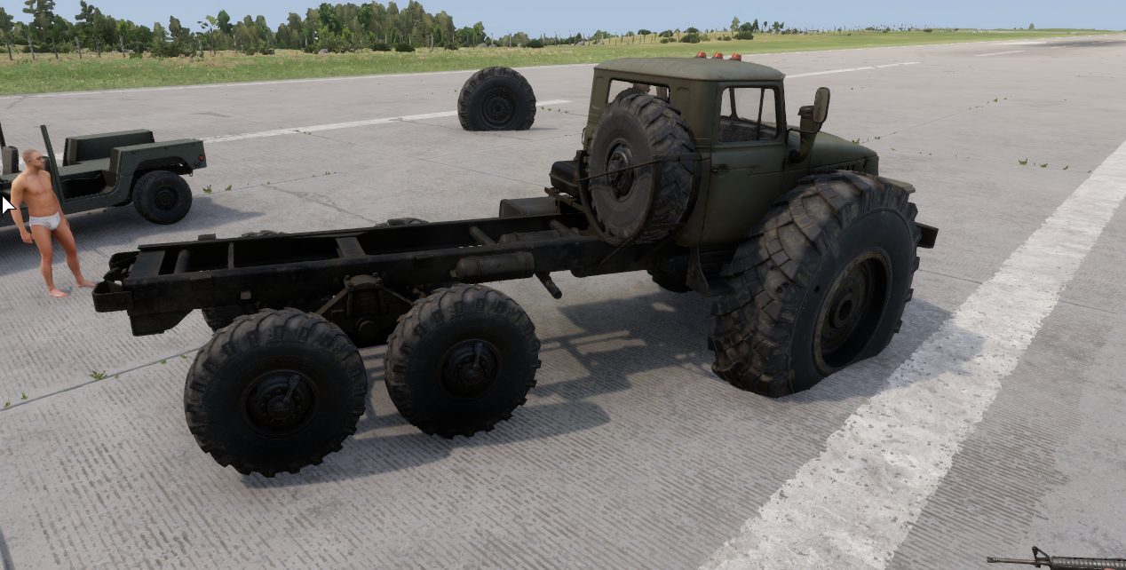
Im just trying something, but wondering if and how, when you scale a prefab in enfusion it dosnt keep the scaled version when you attach it in the slot component? https://i.imgur.com/nVYUBiL.jpeg
 sage lance
hoary gazelle
Im just trying something, but wondering if and how, when you scale a prefab in e...
sage lance
hoary gazelle
Im just trying something, but wondering if and how, when you scale a prefab in e...
There is no way to keep the scale when using the slot manager. If you need to attach it to a model and keep the scale, use “Add Child Prefab”
hoary gazelle
sage lance
There is no way to keep the scale when using the slot manager. If you need to at...
Thanks!
hoary gazelle
sage lance
There is no way to keep the scale when using the slot manager. If you need to at...
i didnt think this would work. But if you change the size of the wheel to scale 2.0 and add it to the slot, it will default back to 1.0. So i had an idea now to make a new genereic enity. Change the size to what i want, add the prefab as a child to the new genereic entity, then attach the new entity to the slo and it kept the size 🤣 And the collision does scale. So just gotta change the raidus in the wheelsim too https://i.imgur.com/9ZlR2F0.png
 supple gulch
is it possible to create halo style damage states in arma reforger?
brisk grotto
supple gulch
is it possible to create halo style damage states in arma reforger?
Would be more of a #enfusion_scripting question
 shell peak
hoary gazelle
i didnt think this would work. But if you change the size of the wheel to scale ...
shell peak
hoary gazelle
i didnt think this would work. But if you change the size of the wheel to scale ...
Regarding this.
When adding a child entity, it seems not to be moving with the vehicle?
I've tried quite a few things and getting lost on why the slot component object isn't moving?
hoary gazelle
shell peak
Regarding this.
When adding a child entity, it seems not to be moving with the ...
it moves fine for me
hoary gazelle
shell peak
Regarding this.
When adding a child entity, it seems not to be moving with the ...
shell peak
hoary gazelle
it moves fine for me
Was that with adding a new component to the slot manager or something else, sorry if I'm confused, just trying to confirm as nothing exactly documented well
hoary gazelle
shell peak
Was that with adding a new component to the slot manager or something else, sorr...
nope havent added anything. Just as mentioned, made a new generic entity put the wheel as a child and scaled it there, then just replaced the wheels
shell peak
Gotcha thanks for clarifying, just trying to figure this out
 shell trail
Hi all, I'm new to modding, and I'm trying to do what I thought would be a simple modification, to give the BRDM a variable zoom scope for the main cannon/MG gun in the turret. I created a project and copied the stock turret as an override into my project and modded the bits I thought needed updated, relating to the min/max zoom and reticle, but although I have managed to change the starting zoom level, and reticle size/colour, I can't get the zoom function to work. The scope is stuck stubbornly at 1.0 (My lowest setting).
As far as I can tell I updated the correct prefab parts, specifically the SCR_2DSightsComponent entries for min/max zoom and reticle base zoom, but it's still not working. I obviously missed something obvious, can anyone point me in the right direction?
Thanks in advance
fickle vigil
Can anyone help me decipher whats wrong with the prtvols? I made sockets and portals for each bsp separately then generated prtvols separately for each room


Would there need to be a "closed" or individual collider for each room or is a utm collider spanning across all rooms fine?
hoary gazelle
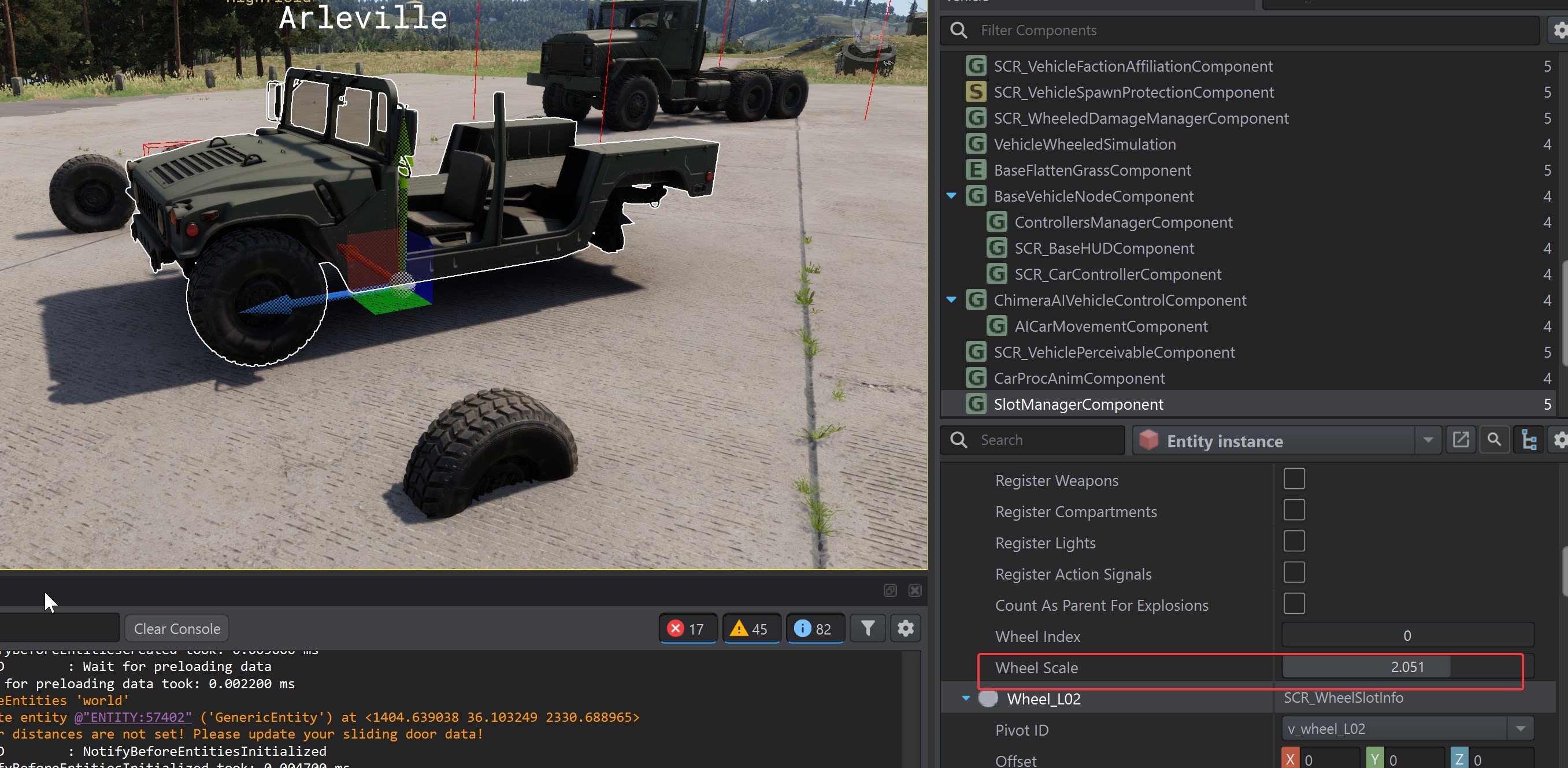
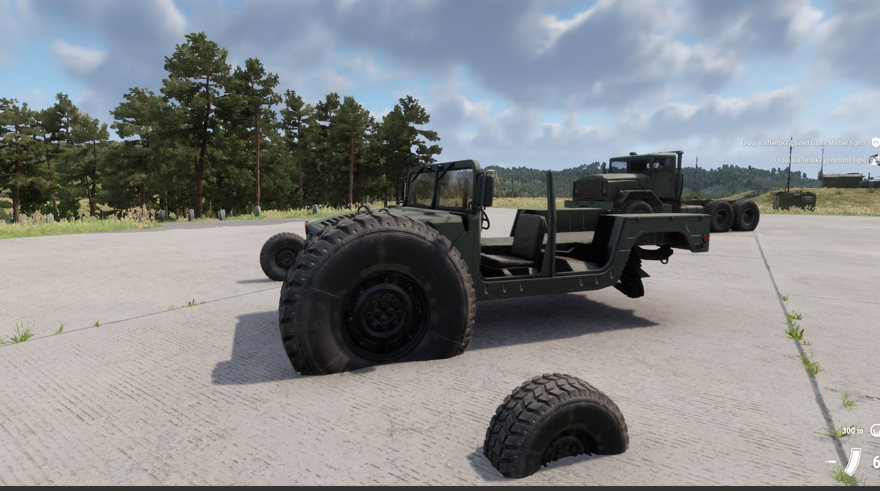
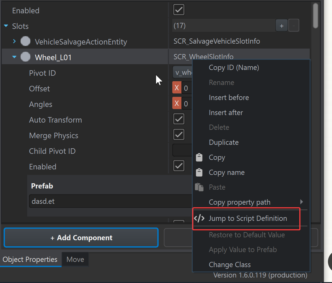
my approach to adding the wheels as a child to a new entity does not translate well with damage, and adding it to the slot component. So ive edited the wheelinfo in the slotcomponent to so you can change scale(even vanilla wheels)
Just dupliacte the wheelinfo with the same name and restart workshop
https://i.imgur.com/yjZRV1c.jpeg
https://i.imgur.com/2U4GLfu.jpeg
https://i.imgur.com/bDAFwpD.png
 shell hedge
Big wheels looks pretty funny
 urban needle
Does anyone know how clothing creation works? I have the object imported into Enfusion and textured, but I don't know what else to do.

 stray bridge
first step: dont use trademarked stuff you dont have the rights to
i made a short text tutorial for clothing in the past, might not be up to date:
short text tutorial on how to import custom clothing, maybe it helps someone out:
**Setup in Blender: **
Rigged Basebody of Arma reforger + your clothing mesh (you can get the basebody by the samples (eg. vest sample) from the ArmaReforger official GIT)
-
make the clothing fit the character (proportional editing, sculpting mode)
-
select AR-Body and then select you Clothing-Mesh
-
go into weight paint mode
-
transfer weights from AR-Body to Clothing-Mesh
-
nor all weights are needed for all clothing eg backpacks only need spine5 most of the time
bottom left of ur screen when after clicked transfer weight's:
-
put "source layers se..." to "By Name" (vertex groups should pop up on the mesh)
-
make sure armature modifier is on the Clothing-Mesh and the armature is selected
-
export the Clothing-Mesh + the Armature (and the Ik-targets, as well as the EntitiyPosition)
-
in tools, tick the export skinning box and reimport it
weight paint:
- find the probably right vertex group to modify
- blue = less influenced by the movement of the player
- red = more influenced
 short harness
Anyone to help me make memory points for a AR platform gun in Arma Reforger?
delicate condor
short harness
Anyone to help me make memory points for a AR platform gun in Arma Reforger?
if you can explain a bit more what part you are stuck with that can be useful. Also have you studied the sample gun for reference?
short harness
I'm currently creating the bones for the gun
short harness
delicate condor
if you can explain a bit more what part you are stuck with that can be useful. A...
Yes, i've used It to scale the IA2 model in the correct Reforger scale
delicate condor
short harness
Yes, i've used It to scale the IA2 model in the correct Reforger scale
did you look at how the bones are set up for the sample gun?
 flint cypress
short harness
flint cypress
short harness
woodycracudo is a diabolical name bro lmao
 lethal frigate
whats the difference between these 2 and normal concrete? i mean i see one is 100mm but other has "Min" what does that mean?
 sly bridge
urban needle
Does anyone know how clothing creation works? I have the object imported into En...
sly bridge
urban needle
Does anyone know how clothing creation works? I have the object imported into En...
622K vertices for a pair of branded (unadvisable) sneakers needs to be the the best thing i've seen this year
 sonic tree
lethal frigate
whats the difference between these 2 and normal concrete? i mean i see one is 10...
sonic tree
lethal frigate
whats the difference between these 2 and normal concrete? i mean i see one is 10...
minimum, i guess 100mm=<
brisk grotto
lethal frigate
whats the difference between these 2 and normal concrete? i mean i see one is 10...
I think it’s how much resource/complexity the engine puts into figuring out pen etc. though I could never find any official info on the wiki. I think min is the version that is more simplistic
lethal frigate
im not sure witch one should i use for buildings , ive been using normal concrete but i dont know if 50cal or bigger can go trought it
im looking for universal good mateiral that can be used both in floors and walls
brisk grotto
It depends on the style of stuff you’re making I guess, if the walls thick enough probably easiest to just use the non-pen concrete material
urban needle
sly bridge
622K vertices for a pair of branded (unadvisable) sneakers needs to be the the b...
in dont see this xDDD
 fierce kraken
Is there a way to assign more than 4 vertex groups in Blender? I am trying to make a dog tag but for some reason I can only assign 4 bones, or at least that's all that registers in Enfusion when Imported.
 calm rune
stray bridge
first step: dont use trademarked stuff you dont have the rights to
calm rune
stray bridge
first step: dont use trademarked stuff you dont have the rights to
Should probably teach him that 600+ verts, 14 meshes and 3 textures for a pair of sneakers is a huge No no before teaching him the set up/injections steps.
remote palm
fierce kraken
Is there a way to assign more than 4 vertex groups in Blender? I am trying to ma...
I can do more then 4 - so it should be possible?
Show your issue with a screenshot 👍🏻
stray bridge
calm rune
Should probably teach him that 600+ verts, 14 meshes and 3 textures for a pair o...
probably but he asked for it and I wrote this before so why not post it 😉
stray bridge
calm rune
Should probably teach him that 600+ verts, 14 meshes and 3 textures for a pair o...
holy I just checked, your right hahah thats crazy
 steel hare
Hej guys, I am about to finish the gas coolers for my coke plant. I followed a modular approach again but run into some problem. Somehow the ground is never straight, so when I assembled my prefabs they always have some slight rotation and height differences. Do you have a trick for me where I can find a really flat area where I can assemble my prefabs?

 calm rune
stray bridge
holy I just checked, your right hahah thats crazy
calm rune
stray bridge
holy I just checked, your right hahah thats crazy
Xbox S starts smoking and the owner has no idea why 🤣
faint viper
steel hare
Hej guys, I am about to finish the gas coolers for my coke plant. I followed a m...
What I used to to for big structures is simply build a plane model and use it as terrain material as base with collider.Atm I’m not home and I can’t show you, in case you don’t manage just let me know and when I’m home I’ll send you the example.
steel hare
Thank you for your response! So you model a large plane, make a collider for it and that's it? Like placing my prefabs on this plane then? 🙂
I ran into another issue now, never happened to me before. But some of the faces of my model are not visible. The faces I recalculated outside in Blender aswel lalready. In Substance painter everything looks fine


in Blender everything looks fine aswell
 remote palm
steel hare
I ran into another issue now, never happened to me before. But some of the faces...
remote palm
steel hare
I ran into another issue now, never happened to me before. But some of the faces...
Would recommend you go into the root folder via Windows where you have the .fbx, .xob and other file, and delete them manually. Then reimport. Mby Workbench had a hickup
steel hare
LOL, it worked! Thank you so much! So deleting it in Workbench and reimporting did not do the job. But deleting in Windows Explorer and then reimporting does the trick. How comes?
remote palm
Hickup, like i said. He still somehow gets some data from the old file. Glad it worked 😉
delicate condor
urban needle
Does anyone know how clothing creation works? I have the object imported into En...
A mod containing such trademarked brand items was just removed from the workshop. so creation starts from not scanned real world items like this
remote palm
And if you have no idea on how to make basic models, clothing should not be your first start imo. Learn the basics of Blender and try yourself on small objects first
urban needle
delicate condor
A mod containing such trademarked brand items was just removed from the workshop...
Okay, thanks for the information
urban needle
remote palm
And if you have no idea on how to make basic models, clothing should not be your...
I tried it with the buildings and it worked, and I felt like continuing with the clothes, but I'll move on to something else xD
remote palm
urban needle
I tried it with the buildings and it worked, and I felt like continuing with the...
I have about 11 monts of blender "experience" and have just now really "tried" myself on my first "real" model with good topology and baking.
urban needle
remote palm
I have about 11 monts of blender "experience" and have just now really "tried" m...
Can it be seen?
You've left me intrigued.
remote palm
urban needle
Can it be seen?
My try for an M42 helmet. I also tried making an Opel Blitz, but i am hard stuck on the cabin.


 urban needle
Wow, that's great, sir.
faint viper
steel hare
Thank you for your response! So you model a large plane, make a collider for it ...
Yep, have you managed to?


Check this out for how it works in the engine
 bitter grove
I’m trying to import a blender model I made but it keep getting to error for my collider that it’s non-orthogonal… so it doesn’t register and import. What does that mean? I know it’s something to do with the shape but I’m not sure how to fix it
 wind storm
Hi, I'm totally new to modeling Arma assets. I have some basic questions:
Does enfusion automatically change the topology to triangles?
Im about to modeling a hospital with three floors. Should the whole building be in one joined mesh, or can for example the walls of a room be four separate objects?
And lamps in the ceiling, should they be part of the building mesh, or separate mesh/object?
Thanks in advance. 🙂
brisk grotto
wind storm
Hi, I'm totally new to modeling Arma assets. I have some basic questions:
Does e...
It will triangulate your mesh, so generally best to do it yourself before import in blender to avoid it doing anything weird.
Lamps and any repeating objects I’d advise adding separately so you can add them in the prefab, always. Always the best approach for reusing props.
Personally I keep the building all under one mesh for export just for ease of use. And if your doing PBR multi it’s less messy with AO etc
 hybrid mountain
faint viper
hybrid mountain
faint viper
@shell hedge weren't you looking for this, feels dumb to ask because I feel like you already tried to use this? Sorry for the ping if so.
shell hedge
hybrid mountain
<@267285803720245258> weren't you looking for this, feels dumb to ask because I ...
The what now
hybrid mountain
Terrain blending shader stuff, unless you were looking for something with more control - like channels
shell hedge
What I would love for that shader is the ability to alpha mask it relative to intersection with terrain
Known in all other game engines as mesh terrain blending
Without it all objects like rocks and even buildings look quite artificial in enfusion
wind storm
brisk grotto
It will triangulate your mesh, so generally best to do it yourself before import...
Thank you!
supple gulch
before i break my pc, is this too complex for coiliders?
 compact scarab
supple gulch
before i break my pc, is this too complex for coiliders?
compact scarab
supple gulch
before i break my pc, is this too complex for coiliders?
Do yourself a favor and use this. Far better than ebt one https://github.com/Weisl/simple_collider
GitHub
This addon allows you to create collider meshes more easily. It provides different operators to generate primitve colliders or convex mesh colliders out of a selection. - Weisl/simple_collider
supple gulch
ight based
 odd rampart
not sure if this is the correct channel but im trying to get a custom car working. following the tutorial when he opens the door it works, but for me it sits me on the ground as if i am in a seat and does nothing to the door.
sonic tree
i could help u
odd rampart
sonic tree
i could help u
That would be great
stray bridge
odd rampart
not sure if this is the correct channel but im trying to get a custom car workin...
can be multiple reasons it doesnt work, hard to guess but probably missing armature, missing weight and vertex group on the door.
Seating pos is defined by one of the emptys in blender called smth like pilot_idle (just on my phone sawy).
Move it around and youll figure out the pos
odd rampart
stray bridge
can be multiple reasons it doesnt work, hard to guess but probably missing armat...
what i dont get is why is it sitting me down im just trying to open the door not get in
and its not the pos of pilot idle cause no matter where i trigger it i am still sat where every i may be
facing what ever dirction i trigger it in
could be weight and vertex group
doubt i did thoes correct
stray bridge
puh sounds and looks like theres alot not correct, luckily napi also offered help he might figure it out with you
thats smth thats hard to figure by just guessing in a dc channel
odd rampart
ye ty for the suggestions hopefully napi can help more in depth
 lavish sparrow
Why is my texture getting super streched at this edge?
 fallow pond
stretched uv
lavish sparrow
fallow pond
stretched uv
Sorry new to creating models. I want to use the base games terrain mat({E0078B932EB17D27}Common/Materials/default_MatTerrainObj.emat), if I'm using an existing game material. How can i go about fixing this?
lavish sparrow


 remote palm
You have to properly UV unwrap your item
lavish sparrow
remote palm
You have to properly UV unwrap your item
I did unwrap it, how is it not proper? I followed some simple blender tutorials that show unwrapping.
remote palm
Because there is still stretching. How does the BCR look of the emat you want to use?
fierce kraken
I have a wedding ring model in game and rigged but sometimes its floating away from the correct position. Is it too small of an object to rig correctly or is it something else?
 worn plover
fierce kraken
I have a wedding ring model in game and rigged but sometimes its floating away f...
worn plover
fierce kraken
I have a wedding ring model in game and rigged but sometimes its floating away f...
is it weighted to something besides the ring finger?
fierce kraken
worn plover
is it weighted to something besides the ring finger?
Just checked the blender save. I weighted it to the whole hand.
Goober intensifies
worn plover
fierce kraken
Just checked the blender save. I weighted it to the whole hand.
make sure u set all transforms also
lavish sparrow
remote palm
Because there is still stretching. How does the BCR look of the emat you want to...
You can't view the BCR on the MatTerrain class
 worn plover
lavish sparrow
You can't view the BCR on the MatTerrain class
worn plover
lavish sparrow
You can't view the BCR on the MatTerrain class
switch it to a matPBRbasic and check a .edds BCR that isnt parametric
it could just be the terrain mat
fierce kraken
fierce kraken
Just checked the blender save. I weighted it to the whole hand.
Redid the painting.
 worn plover
fierce kraken
Redid the painting.
worn plover
fierce kraken
Redid the painting.
ye that should work
fierce kraken
worn plover
ye that should work
It worked a treat. It no longer floats away during animations.
fickle vigil
Wondering how I go about this. Very tall building, 99% of triangles are in the top 3 floors. I was wanting to only have most of those triangles render when you are near the top but right now, LOD0 still renders at ground floor. The top 3 floors are a separate mesh/prefab. Whats the best method to acheive this? Nothing on the building is accessible until you are in or on top of the top 3 floors. Is it showing LOD0 from ground floor because the top mesh is so many triangles? Top part is around 1 million at LOD0

 sonic tree
first of all reduce mesh, then u can try to work around with lods u might try to separate inside and change lods settings if u want to achive this render
 onyx sonnet
anyone know if it is allow if i wanted to edit the base game character model?
or is that against licensing?
hoary gazelle
compact scarab
Do yourself a favor and use this. Far better than ebt one https://github.com/We...
@supple gulch just a little self plug but ive made this including collision generator for reforger https://youtu.be/m3qkYLVp60Y?si=tadeAT1_xtHQSHQ9
 chrome crater
It finally works. Im still learning but step by step it works and looks better. Next project is a pair of gloves. After that im going to start with the fullghillie🤯🥳


 steel hare
fickle vigil
Wondering how I go about this. Very tall building, 99% of triangles are in the t...
steel hare
fickle vigil
Wondering how I go about this. Very tall building, 99% of triangles are in the t...
maybe make the seating elements, sun umbrellas, the lower balcony railing into single objects and prefabs. The ladder into the pool aswell. This way you can have LOD0 for these small objects only rendered when the user approaches it. I had a similar problem with large structure am working on so I make them modular from the beginning on and assemble them in Enfusion workbench into one big prefab.
brisk grotto
@fickle vigil id also suggest some LOD0 optimisation. Can’t see any good reason why that should be 1m
fickle vigil
steel hare
maybe make the seating elements, sun umbrellas, the lower balcony railing into s...
Thank you for taking the time to write out a thoughtful answer instead of just replying with “make it less poly”. I’ll try to break it down like you said, appreciate it🤘
fickle vigil
brisk grotto
<@483104824271831043> id also suggest some LOD0 optimisation. Can’t see any good...
It has a lot of detail and artwork at the top. LOD0 optimization in this case is implied. My question was about controlling when LODs pop in👍
brisk grotto
fickle vigil
It has a lot of detail and artwork at the top. LOD0 optimization in this case is...
Even with artwork, details etc 1m is way too fucking high for any reforger building honestly. Most I've ever pushed it to is about 500k and even that really should have been better optimised. 1m is going to fry console players especially.
Base game buildings average 30-50k, with some occasioanlyl being 100-150k for more complex stuff.
Sure you could do it, but why? Better to take time to actually optimise things. Either someones used a lot of subvidision modifiers or it's got a load of assets designed for UE5
fickle vigil
brisk grotto
Even with artwork, details etc 1m is way too fucking high for any reforger build...
For the second time, your reply has absolutely nothing to do with my question and I already said I plan on optimizing LOD0.
brisk grotto
fickle vigil
For the second time, your reply has absolutely nothing to do with my question an...
You literally didn’t say that anywhere in your message but ok
fickle vigil
brisk grotto
You literally didn’t say that anywhere in your message but ok
I said "LOD0 optimization in this case is implied" but prob not the best way to say it. By the time I'm done with optimization it will only be a couple 100k and once I get the LOD distance thing locked in, when you are at the top and rendering it at LOD0, since its so high everything else will be rendering at LOD4/5 so it should run fine. I'm just trying to figure out the best way to make sure LOD0/1 wont render when someone is on the ground looking up at it
brisk grotto
fickle vigil
I said "LOD0 optimization in this case is implied" but prob not the best way to ...
Not sure if the engine does take vertical height into consideration for LODs, especially if there isn't a lot of other stuff around it. I think there is a debug tool that shows LOD stages in-engine so you can figure out when it's changing
fickle vigil
brisk grotto
Not sure if the engine does take vertical height into consideration for LODs, es...
Engine does not seem to understand height of the object. Will def need to find a way to tell engine mesh is elevated.
compact scarab
fickle vigil
Engine does not seem to understand height of the object. Will def need to find a...
bounds?
fickle vigil
compact scarab
bounds?
Bounds as in?
hybrid mountain
for LODs they tend to use pixel size scale
compact scarab
Bounding Box on meshobject component was my thought
hybrid mountain
so basically how much space the bounding box is taking up on the players screen, below a set amount of pixels drops it, in scale, default settings usually means LOD0 is only rendered very close or inside of an object
and consoles are far more aggressive when skipping, iirc they either skip LOD0 or they skip mipmap level 0 (drop to next texture resolution)
can't remember which, but you can also manage import settings based on platform as well
fickle vigil
Thank you for the knowledge, that helps a ton. Neither bounding box size/scale and pixel size filter seem to fix the LOD0 issue. No matter what I set in LOD factors or pixel size filter, the mesh still renders LOD0 when a player is at the bottom of the building, depsite all mesh being 150m above.
 mint summit
How can i make this to where i can wear these shoes? They are lower than the ankle how can i just have the feet show with the shoes, instead of having to try to add the feet in.
 mint summit
i got er figured out.
bitter grove
why is this not working as a collider? i really dont understand whats causing that error

 compact scarab
bitter grove
why is this not working as a collider? i really dont understand whats causing th...
compact scarab
bitter grove
why is this not working as a collider? i really dont understand whats causing th...
It needs better topology
bitter grove
i feel thats clean tho for 150 tris?
compact scarab
compact scarab
bitter grove
i feel thats clean tho for 150 tris?
Ya maybe not that. Idk but this gives some info
bitter grove
YEAH. I just needed to apply all transforms it seems. that helped
onyx sonnet
onyx sonnet
anyone know if it is allow if i wanted to edit the base game character model?
@wet iron
compact scarab
onyx sonnet
<@1257691070129766403>
Not in a way that requires you to rip it.
onyx sonnet
Ty
 crystal kestrel
hi i'm new to moding enfusion and working on a helmet which I'd like to not clip my camera or scope and ironsight views in first person. is there a component i can add that will turn off its visibility for only the player when in first person or when aiming a weapon? i have screenshots of third vs first person views


 crystal kestrel
okay i figured it out. just hadd to add the default head_cipping.edds and apply user alpha bias + disable alpha shadow settings in the emats. super easy fix!
 amber oyster
 fallow pond
in blender
brisk grotto
crystal kestrel
okay i figured it out. just hadd to add the default head_cipping.edds and apply ...
For the record it just needs user alpha bias disabled, not specifically yhe head clipping if it's just normal headgear. The clipping is for more complex stuff like ghillies etc
surreal ore
brisk grotto
For the record it just needs user alpha bias disabled, not specifically yhe head...
Except all vanilla helmets use the head clipping...
It's there to provide a transition between visible and not visible. As opposed to just popping in and out of visibility.
hoary gazelle
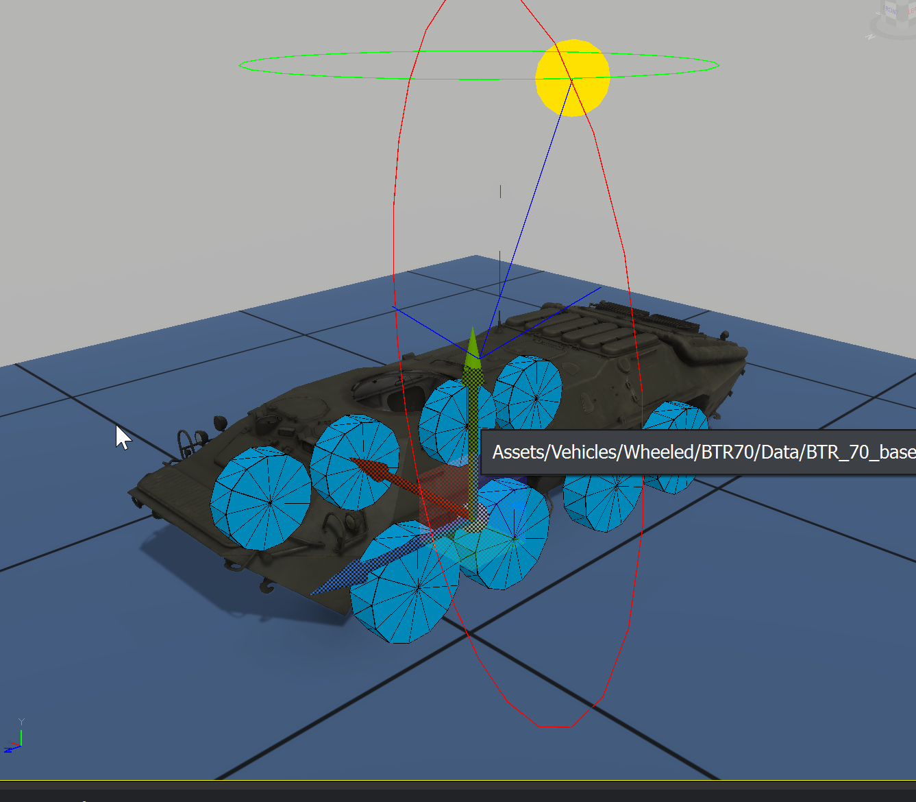
Just wondering, whats the point of adding wheel collision to the body mesh? the wheel placed on them has a collider that will be sloted on later. On the bodies i see in vanilla, some has and some dont have like this btr has, but LAV dosnt have https://i.imgur.com/DUE3udx.png
 fallow pond
to trigger mines if I remember correctly
hoary gazelle
fallow pond
to trigger mines if I remember correctly
ah ye they are called minetriggers indeed those collisions. But just odd that then the LAV25 dont have that, maybe its old stuff?
bitter grove
this is really blowing me out. why is the game not reading the UV map? using the defaultterrrain.emat

 brisk grotto
bitter grove
this is really blowing me out. why is the game not reading the UV map? using the...
brisk grotto
bitter grove
this is really blowing me out. why is the game not reading the UV map? using the...
Hard to say without some details but it looks like those sides of the trenches aren’t actually unwrapped just the rest is
And that’s a guess based on the smart UV project 
bitter grove
yeah i started over just doing a test and i feel any way i mark this and unwrap it the side are strecthed
 calm rune
bitter grove
yeah i started over just doing a test and i feel any way i mark this and unwrap ...
calm rune
bitter grove
yeah i started over just doing a test and i feel any way i mark this and unwrap ...
Apply all transforms before unwrapping
In object mode click on the model then Shift + A
bitter grove
calm rune
Apply all transforms before unwrapping
I thought I had done this but I’ll try again tomorrow and see what the result is
fallow pond
generally if you dont know what your doing with unwrapping your uv islands should be the same size
bitter grove
Yeah I know they should all be same sized squares more or less, that’s why was confused with how my map was or why it was like that
 young shard
fallow pond
in blender
young shard
fallow pond
in blender
Better advice than pointing him to someplace to download models.
shell hedge
bitter grove
yeah i started over just doing a test and i feel any way i mark this and unwrap ...
Try make the slope in the trench walls larger, close to 90 degrees = bad
There is some funny stretching on slopes, it might be exclusive to your shape which is not convex I guess???
Texture is fine on the bevel but not on the "wall" of the trench
I wonder if the shader is just mapping it from 6 directions
From outside the bounding box or something
Idk

calm rune
shell hedge
There is some funny stretching on slopes, it might be exclusive to your shape wh...
When I first started modelling I had the same issue. Apply all transforms before unwrapping solved the issues every single time.
fickle vigil
Does anyone know the reasoning behind this collider overlap rule? Wondering if they say not to overlap because it will cause performance issue or if its because colliders may not work properly if overlapping? Working on a big model and want to know how detailed I need to be on the overlapping rule. Thanks
 sonic tree
fickle vigil
Does anyone know the reasoning behind this collider overlap rule? Wondering if t...
sonic tree
fickle vigil
Does anyone know the reasoning behind this collider overlap rule? Wondering if t...
may not work properly, and underperform
for example some collider overlaped by mistake in my model
and vehicle started flying around map
surreal ore
fickle vigil
Does anyone know the reasoning behind this collider overlap rule? Wondering if t...
You don't want 2 colliders to actively be colliding with one another and that's what happens with overlapping colliders.
fickle vigil
surreal ore
You don't want 2 colliders to actively be colliding with one another and that's ...
If its all merged into 1 Tri-Mesh, does it matter? Would overlapping or interior faces of one tri-mesh count as overlapping ?
surreal ore
fickle vigil
If its all merged into 1 Tri-Mesh, does it matter? Would overlapping or interior...
I would guess it matters if the developers of the game told you not to do it. They don't tell you not to do things for no reason.
fickle vigil
surreal ore
I would guess it matters if the developers of the game told you not to do it. Th...
It says "overlap of more Objects...". I was asking if multiple objects merged into one object, would count as "more objects" or if maybe they are saying dont overlap a tri-mesh with a box collider since those would be two separate objects in enfusion
surreal ore
fickle vigil
It says "overlap of more *Objects*...". I was asking if multiple objects merged ...
UTM_Weapon supplied by B.I. in https://github.com/BohemiaInteractive/Arma-Reforger-Samples/blob/main/SampleMod_NewWeapon/Assets/Weapons/Rifles/SampleWeapon_01/SampleWeapon_01.fbx

At least in this reguard it seems fine.
Would need clarification on if the import setting "Merge Tri Meshes" yields the same result.

 small heath
When im modeling my magazine, do I need to model the bullets? Also, should I model it with the spring up or down?
sly bridge
@ember eaglewrong channel
steel hare
fickle vigil
Thank you for taking the time to write out a thoughtful answer instead of just r...
How did it work out for you to break it down? It can turn out to be more work of course but in the end it should increase performance and gives you way more flexibility
remote palm
small heath
When im modeling my magazine, do I need to model the bullets? Also, should I mod...
Not really, you just need a “full” mag and one empty. You will assign both in the mag prefab and it will switch depending on if it is “full” or empty.
fickle vigil
steel hare
How did it work out for you to break it down? It can turn out to be more work of...
Got it down to 300k. Runs extremely well. Will get it down more when I have the time but going to work on bsp and lighting next
fickle vigil
steel hare
How did it work out for you to break it down? It can turn out to be more work of...
I get the same/more fps from up there than I do in vanilla areas but when someone is on the ground, it renders at LOD0 even when it’s about 150m above them and not in their fov. Would really like to figure out what I’m doing wrong there. LODs act as if you are point blank with the objects if you are near the bottom of tower
bitter grove
What would be the best way to add a field like this? So I could paint it like the wheat fields and grass

 ember eagle
sly bridge
<@1417926978262270093>wrong channel
ember eagle
sly bridge
<@1417926978262270093>wrong channel
Can I just answer the question I know I’m at the wrong channel too say that in here. I’m just saying if he is working on his mod.
brisk grotto
bitter grove
What would be the best way to add a field like this? So I could paint it like th...
Look at the setup of the games existing grass etc, I suspect it’s probably planed overlayed like they do with bushes as trees, you’d have to replicate that with your desired textures
sly bridge
ember eagle
Can I just answer the question I know I’m at the wrong channel too say that in h...
you weren’t answering you were asking. not sure why is it this hard to ask/answer in multiple threads that have that particular purpose
ember eagle
sly bridge
you weren’t answering you were asking. not sure why is it this hard to ask/answ...
Listen here I’m asking him about the mod if he working on it still that I was saying but you guys take down my message.
 wary inlet
bitter grove
What would be the best way to add a field like this? So I could paint it like th...
wary inlet
bitter grove
What would be the best way to add a field like this? So I could paint it like th...
Totally doable, enfusion merges grass type with ground texture, so you can duplicate existing dirt material and assign a new grass material to it, then you will need your own texture
small heath
remote palm
Not really, you just need a “full” mag and one empty. You will assign both in th...
So, model one with bullets and one without?
bitter grove
brisk grotto
Look at the setup of the games existing grass etc, I suspect it’s probably plane...
You think that’s making a model in blender and texturing it then adding it or would it be just a texture? I need to look deeper into how they did the grasses/crop fields
remote palm
small heath
So, model one with bullets and one without?
Yes, otherwise look at vanilla magazines
small heath
Kk
tepid cloak
anyone got any idea why spawned items (scripted) would just disappear on certain angles of a objet?
 ancient walrus
Bounding box probably due to model size or shape changing with animations in my experience . Normally happens in SP spawn for me too with GM .
IIRC I made sure geometry was as large as furthest animated part or something similar or a plain axis was
 burnt surge
tepid cloak
burnt surge
tepid cloak
Nice with this crate in the background  , any tips how you did this or how to do that? Would be cool
tepid cloak
ancient walrus
IIRC I made sure geometry was as large as furthest animated part or something si...
will check this out man
tepid cloak
burnt surge
Nice with this crate in the background <:coolfrog:1356650288529936597> , any tip...
Hey Sentry, this is how my floating/spinning crate works so far:
The spawner creates the crate entity and passes runtime config into the crate component.
The crate runs a server tick every m_fUpdateIntervalSeconds.
Float/bob uses a sine wave:
y = baseY + sin(elapsed * frequencyHz * TAU) * amplitude
Spin uses elapsed time:
yaw = baseYaw + elapsed * rotateSpeedDegPerSec
Pickup still runs in the same tick (vehicle proximity check), so movement + gameplay are one loop.
Current implementation is in:
ARGH_WeaponCrateSpawnerComponent.c (line 2153)
ARGH_WeaponCrateSpawnerComponent.c (line 2180)
very much wip
class Sentry_FloatingCrateComponentClass : ScriptComponentClass
{
}

class Sentry_FloatingCrateComponent : ScriptComponent
{
    protected static const float TAU = 6.2831853;

    [Attribute(defvalue: "0.25", uiwidget: UIWidgets.EditBox, desc: "Vertical bob amplitude in meters")]
    float m_fFloatAmplitude;

    [Attribute(defvalue: "0.75", uiwidget: UIWidgets.EditBox, desc: "Bob frequency in Hz")]
    float m_fFloatFrequencyHz;

    [Attribute(defvalue: "65", uiwidget: UIWidgets.EditBox, desc: "Yaw spin speed in deg/sec")]
    float m_fRotateSpeedDegPerSec;

    [Attribute(defvalue: "0.05", uiwidget: UIWidgets.EditBox, desc: "Server tick interval in seconds")]
    float m_fUpdateIntervalSeconds;

    protected float m_fElapsedSeconds;
    protected int m_iTickIntervalMs;
    protected vector m_vBaseOrigin;
    protected vector m_vBaseAngles;

    override void OnPostInit(IEntity owner)
    {
        super.OnPostInit(owner);

        m_vBaseOrigin = owner.GetOrigin();
        m_vBaseAngles = owner.GetAngles();
        m_fElapsedSeconds = 0.0;

        if (!Replication.IsServer() || !GetGame())
            return;

        m_iTickIntervalMs = m_fUpdateIntervalSeconds * 1000.0;
        if (m_iTickIntervalMs < 20)
            m_iTickIntervalMs = 20;

        GetGame().GetCallqueue().CallLater(Sentry_ServerTick, m_iTickIntervalMs, true, m_iTickIntervalMs);
    }

    protected override void OnDelete(IEntity owner)
    {
        super.OnDelete(owner);

        if (GetGame())
            GetGame().GetCallqueue().Remove(Sentry_ServerTick);
    }

    protected void Sentry_ServerTick(int intervalMs)
    {
        if (!Replication.IsServer())
            return;

        IEntity owner = GetOwner();
        if (!owner)
        {
            if (GetGame())
                GetGame().GetCallqueue().Remove(Sentry_ServerTick);
            return;
        }

        float dt = intervalMs * 0.001;
        m_fElapsedSeconds = m_fElapsedSeconds + dt;

        if (m_fFloatAmplitude > 0.0 && m_fFloatFrequencyHz > 0.0)
        {
            vector pos = m_vBaseOrigin;
            pos[1] = m_vBaseOrigin[1] + Math.Sin(m_fElapsedSeconds * m_fFloatFrequencyHz * TAU) * m_fFloatAmplitude;
            owner.SetOrigin(pos);
        }

        if (m_fRotateSpeedDegPerSec != 0.0)
        {
            vector angles = m_vBaseAngles;
            angles[1] = m_vBaseAngles[1] + (m_fElapsedSeconds * m_fRotateSpeedDegPerSec);
            owner.SetAngles(angles);
        }
    }
}
Wow cool thank you so much very appreciated! ❤️
tepid cloak
Use wisely I see cool uses for like floating rocks u can climb to places or platform style gaming with this
When models meets #enfusion_scripting
steel hare
fickle vigil
I get the same/more fps from up there than I do in vanilla areas but when someon...
maybe you can try to split the building just below the inner area in the top starts? That you have the foundation levels as an own object containing a large occluder inside and on top of it arrange the roof top as an own object aswell. Then assemble them together in Enfusion to one big prefab
 delicate condor
fickle vigil
Thank you for the knowledge, that helps a ton. Neither bounding box size/scale a...
delicate condor
fickle vigil
Thank you for the knowledge, that helps a ton. Neither bounding box size/scale a...
if mesh is part of the building the building is what dictates the lod use I believe.
the other objects would have to be separate entitites for them to have their own independent lodding
fickle vigil
delicate condor
if mesh is part of the building the building is what dictates the lod use I beli...
Ah ok. I’ll just split them all up into separate ents. Ty!
delicate condor
I would maybe split tall building like this into 3 parts even
maybe depending on the polycount and interior details
fickle vigil
delicate condor
I would maybe split tall building like this into 3 parts even
Its around ~300k polycount spread across 16,800m^2 with 95% of polycount in those top 3 floors, below that its empty inside and very low poly. Just to confirm, you are saying split it up into multiple separate entities that are not parented to each other? Currently, its a "building" with poly split up into 6 mesh across 6 "buildings" that are children of main mesh/building
delicate condor
child prefabs can have separate lod handling values if I remember right, but essentially yes if you want it to lod at distance on the top that part needs to be separate entity
but lod switch is not just distance based
fickle vigil
delicate condor
but lod switch is not just distance based
Ive tried every combination of pixel size filter and lod factors and it still renders at LOD0 from ground level as if you are at that top level. If camera is at roof height and I start backing off, LODs kick in quicker than being at ground level. Going to split it up into separate ents like you said and hopefully that gets the job done. Thanks for the info👍
delicate condor
fickle vigil
Ive tried every combination of pixel size filter and lod factors and it still re...
lod level draw for the whole building is expected to behave like that since its single object
fickle vigil
Copy🫡
fickle vigil
Is there anyway I could link the entities like parent/child does so that it can be placed down in one prefab but still be considered separate ents? I'm not sure if a comp would be the way to go for a static building of this size? Its a mall made up of 6 separate meshes
 leaden trench
You can get away with high poly count for ship; out in ocean there is nothing else for the game to render but water. The way I would do it is have one model for the hull/walls, and then decorate it with props. Do it like buildings are done.
supple gulch
Make sure that once the model is ready you check :
The normals of the model, you can do this by selecting the entire model, going to the mesh tab and recalculating 'outside' this makes sure the players can see the model
Make sure that any floors, walls etc are 3 dimensional if they can be viewed from multiple sides, if they are not it'll allow people to see through the ship in places
triangulate the faces (you can do this by right clicking and selecting the triangulate faces option), if you don't do this the mesh may behave weirdly in the Arma, have its poly count sky rocket to a ridiculous level or simply have the game unable to actually process what you have imported.
You should be good just doing one set of lods but you could save on performance if you make the interior areas aggressively reduce in quality when compared to the exterior
Oh and the biggest thing I can think of is, if you are going to decorate the rooms from the start do the absolute bare minimum.
A sick bay doesn't need a dozen beds, IVs everywhere and loads of grebles to get the point across that it's a medical room, a few beds, some pretty simple medical equipment and people will get the point without dying from potentially performance issues
compact scarab
fickle vigil
Is there anyway I could link the entities like parent/child does so that it can ...
It's probably not this easy but you could try unchecking merge meshes on the import settings of the model. Probably still just counts it as one entity though.
You could child them in the hierarchy manually, but not as a prefab also and see results.
If it doesn't have to be spawned
Or you could just use a world layer maybe
Like its a prefab kindve, to group them into one thing. Not an entity, but maybe could find an angle.
bitter grove
shell hedge
Try make the slope in the trench walls larger, close to 90 degrees = bad
Yeah this worked making it not 90. Is there a fix in the works or anything so you can make it 90? That’s kind of frustrating but I understand if the engine has its limits
brisk grotto
bitter grove
Yeah this worked making it not 90. Is there a fix in the works or anything so yo...
Not an engine issue, apply all transforms see if it then behaves when you unwrap it again
calm rune
bitter grove
Yeah this worked making it not 90. Is there a fix in the works or anything so yo...
Did you do what I told you to? That will fix it for 90..
calm rune
brisk grotto
Not an engine issue, apply all transforms see if it then behaves when you unwrap...
I told him to do that a couple days ago. Seems like he didn’t try it or ignored it lol. Now it’s an “engine issue” lol
bitter grove
calm rune
Did you do what I told you to? That will fix it for 90..
No I did do what you told me to do, sorry for not replying.
It worked for unwrapping in blender, the UV map looked great with the checkered squares. However, it still stretched on the sides when imported into the engine
compact scarab
There's a shader feature that deals with that but idk if reforger has that feature. Like trilinear or something.
calm rune
I need to test this out myself bcz something doesn’t seem rights
compact scarab
TriPlanar UV was what I used in unity from Microsplat for that
no idea if reforger has an equivalent
 bitter grove
calm rune
I need to test this out myself bcz something doesn’t seem rights
bitter grove
calm rune
I need to test this out myself bcz something doesn’t seem rights
For examaple, this just took 10 mintutes to create and import. applied all trans before unwrapping, UV grid looks great and then there is still stretch on the 90s


i could still be doing something wrong, but my other models i made yesterday looked fine when i made the angles not 90
brisk grotto
bitter grove
For examaple, this just took 10 mintutes to create and import. applied all trans...
Are you exporting with the blender plugin or a standard fbx?
bitter grove
standarded FBX, i can try the blender pluggin real quick
bitter grove
I still have it at 4.2.9
brisk grotto
dunno if the latest plugin works for that, they always suggest the current LTS
if you want ping me the fbx or blend I can test it my end on LTS see what it does via plugin
bitter grove
yeah i do need to update that's prolly why there is no selection for the collider materiel , it still exported it though but it didnt help the 90s
calm rune
compact scarab
Triplaner looks horrible. Way too tiled.
compact scarab
calm rune
Triplaner looks horrible. Way too tiled.
Yeah. He has stochastic clustering which is amazing for anti tiling (better than his anti tiling module lol). Not sure if it works with the triplanar module
surreal ore
fickle vigil
Is there anyway I could link the entities like parent/child does so that it can ...
That's exactly what vanilla buildings do. What are you confused about?
Make parent prefab, make child prefabs. Open parent prefabs and add child prefabs to them. Look at any of the buildings that already exist. They all have child doors, windows and furniture.
calm rune
bitter grove
For examaple, this just took 10 mintutes to create and import. applied all trans...
Works fine for me
 calm rune
Yep, works as I expected lol. No stretching lol


Wait are you using the paint tool to paint it as terrain?
brisk grotto
calm rune
Yep, works as I expected lol. No stretching lol
There’s some difference between your mesh as his, it’s not flat down he’s got a bit of a smooth edge between so wondering if that’s somehow the cause
You’ve also got a custom material and texture not the terrain?
calm rune
brisk grotto
You’ve also got a custom material and texture not the terrain?
Pretty sure the issue is that he is using the paint tool to texture it. That I can not help with. Never stepped into the terrain tools.
brisk grotto
calm rune
Pretty sure the issue is that he is using the paint tool to texture it. That I c...
No he’s not texturing it at all he’s applying the game material that makes it use the terrains texture
calm rune
brisk grotto
No he’s not texturing it at all he’s applying the game material that makes it us...
I looked. Couldnt find that specfic game material
calm rune
brisk grotto
No he’s not texturing it at all he’s applying the game material that makes it us...
This one uses BI game mats and still not stretching
 fickle vigil
surreal ore
That's exactly what vanilla buildings do. What are you confused about?
fickle vigil
surreal ore
That's exactly what vanilla buildings do. What are you confused about?
I was having an issue where the mesh in child prefabs were scaling LODs relative to parent prefab mesh. A mesh that would be at LOD5 if placed on its own, would instead be at LOD0 or LOD1 at same distance if its a child prefab. Goat suggested making all prefabs separate entities which does resolve the issue but the model is a large building so I was looking for a way to place it down as one prefab so that all mesh dont need lined up manually. Basically a way to group them into one ent like parent child relationship does, but without actually having that relationship so I can have LODs scale independently
brisk grotto
calm rune
I looked. Couldnt find that specfic game material
default_MatTerrainObj.emat
He sent me his mesh and it works fine with other textures, it's only the matterrain that doesn't like the trench edges
surreal ore
fickle vigil
I was having an issue where the mesh in child prefabs were scaling LODs relative...
What specifically is the problem though, If parent is at LOD0 the child should be at LOD0 as well. Example, If a building is large enough on my screen to be at LOD0, then the signs, doors, windows and such on it should be at LOD0 as well. What children are you having problems with? Give me a specific example and maybe we can figure something out.
bitter grove
calm rune
Works fine for me
Yeah the UVs are fine, like Casey was saying the terrain tool painting over it doesn’t like the 90 degree edges. I could texture them in SP and use custom textures but I want them to blend with the terrain better
 mortal marsh
Evening all 🙂 Im trying to attach a patch prefab to a hat using slots in BaseLoadoutClothComponent
Its working as expected on the object, but when worn it returns to the model origin
I've seen BI and other modders use this system to attach pouches etc. so I dont think it needs to be rigged in order to be attached wherever you want - Any ideas what I could be missing?

 tepid cloak
How the f did I end up here 🤣
brisk grotto
I think the copyright police will be on the way shortly
calm rune
 tepid cloak
soo I am never publishing it 😄 I am using it for research for a tool I am creating that generates Kart Style race tracks as OBJ's 🙂
 surreal ore
mortal marsh
Evening all 🙂 Im trying to attach a patch prefab to a hat using slots in `BaseL...
surreal ore
mortal marsh
Evening all 🙂 Im trying to attach a patch prefab to a hat using slots in `BaseL...
Choose the head bone as the slots PivotID
mortal marsh
I'll give that a go, cheers Zelik
surreal ore
mortal marsh
I'll give that a go, cheers Zelik
Oh, for those to actually be shown in the drop down the MeshObject is required to have the "worn" item, because those PivotIDs are populated from the MeshObject for some reason.
surreal ore
tepid cloak
soo I am never publishing it 😄 I am using it for research for a tool I am creat...
Apparently, from what I've read that "doesn't matter"
tepid cloak
i was told its not allowed to be published dont want to ruffle feathers 🙂
tepid cloak
tepid cloak
soo I am never publishing it 😄 I am using it for research for a tool I am creat...
if anyone wants to give this a go 🙂 https://github.com/josharghhh/KARTMAKER-ARGH
tepid cloak
proof of concept usign above
took about 30 mins to bring my generated model into blender figure out first time setting up from my tool and get in game
leaden trench
tepid cloak
proof of concept usign above
Reminds me of an article I read the other day: https://sandboxspirit.com/blog/art-of-roads-in-games/ Maybe you could ask your bot to try some of the ideas in there like clothoids
 tepid cloak
I like this shit fuck yeah
i am usign bezier splines for road gen 😛

would love to see others creations this one took me 5 mins now i know what im doing obv not uv'd yet etc will work on that if i can man procedural
then the real test is if i can make it work in engine as a plugin
tepid cloak
leaden trench
Reminds me of an article I read the other day: https://sandboxspirit.com/blog/ar...
so quick math read up this doesnt seem hard too hard to implement tbh
currentlyI use smooth Beziers but don’t enforce curvature ramping the sharp-turn cleanup happens now (sanitizeRoadSamples), so clothoids can replace that corner-fillet logic directly for my web app , thank you 🙂

Medium
The clotoid, defined by A² = R • L, revolutionises engineering, medicine and technology through mathematically perfect transitions.
 hexed sandal
tepid cloak
hexed sandal
tepid cloak
I need to do something like this for my map of Seattle... I have an idea of how to do the first photo with about five lanes, but the other image with the T-junction and the bike lane, including the crosswalk and sidewalks, has me stumped!
tepid cloak
seems clothoids is answer my dude
see maths in article above
  function buildUnitBiClothoid(theta, steps = 18) {
    const th = clamp(Math.abs(theta), 1e-4, Math.PI - 1e-4);
    const segs = clamp(Math.round(steps), 8, 96);
    const ds = 2 / segs;
    let phi = 0;
    let x = 0;
    let y = 0;
    const points = [{ x: 0, y: 0, t: 0 }];
    for (let i = 0; i < segs; i++) {
      const sm = (i + 0.5) * ds;
      const k = sm <= 1 ? (th * sm) : (th * (2 - sm));
      const phiMid = phi + 0.5 * k * ds;
      x += Math.cos(phiMid) * ds;
      y += Math.sin(phiMid) * ds;
      phi += k * ds;
      points.push({ x, y, t: (i + 1) / segs });
    }
    const sinTh = Math.sin(th);
    if (!Number.isFinite(sinTh) || Math.abs(sinTh) < 1e-6) return null;
    const cutY = y / sinTh;
    const denX = 1 + Math.cos(th);
    let cut = cutY;
    if (Math.abs(denX) > 1e-6) {
      const cutX = x / denX;
      if (Number.isFinite(cutX)) cut = (cutY + cutX) * 0.5;
    }
    if (!Number.isFinite(cut) || cut <= 1e-4) return null;
    return { points, cutScale: cut };
  }

  function tryInsertClothoidCorner(out, P, C, N, cfg) {
    const {
      dedupEps = 1e-3,
      minSeg = 0.05,
      width = 4,
      hard = 0,
      ang = 0,
      lin = 0,
      lout = 0,
      din = v3(1, 0, 0),
      dout = v3(1, 0, 0),
    } = cfg || {};
    if (!Number.isFinite(ang) || ang <= 1e-3) return false;
    const turnSign = (din.x * dout.z - din.z * dout.x) >= 0 ? 1 : -1;
    const steps = clamp(Math.round(8 + hard * 12 + ang * 8), 8, 48);
    const unit = buildUnitBiClothoid(ang, steps);
    if (!unit) return false;

    const targetRadius = width * (0.58 + 0.34 * hard);
    const desiredL = Math.max(minSeg * 0.7, targetRadius * ang);
    const maxCutIn = lin * 0.48;
    const maxCutOut = lout * 0.48;
    const maxL = Math.min(maxCutIn, maxCutOut) / Math.max(unit.cutScale, 1e-6);
    const minL = minSeg * 0.7;
    if (!Number.isFinite(maxL) || maxL <= minL) return false;
    const L = clamp(desiredL, minL, maxL);
    const cut = unit.cutScale * L;
    if (!Number.isFinite(cut) || cut <= minSeg * 0.5 || cut >= lin || cut >= lout) return false;

    const tIn = clamp(cut / lin, 0.04, 0.48);
    const tOut = clamp(cut / lout, 0.04, 0.48);
    const A = lerpSampleNode(C, P, tIn);
    const B = lerpSampleNode(C, N, tOut);
    const left = v3(-din.z, 0, din.x);
    const inward = turnSign >= 0 ? left : mul(left, -1);

    pushSampleUnique(out, A, dedupEps);
    const den = Math.max(1, unit.points.length - 1);
    for (let i = 1; i < unit.points.length - 1; i++) {
      const lp = unit.points[i];
      const ux = lp.x * L;
      const uz = lp.y * L;
      const t = i / den;
      const pXZ = add(add(v3(A.pos.x, 0, A.pos.z), mul(din, ux)), mul(inward, uz));
      pushSampleUnique(out, {
        pos: v3(pXZ.x, (1 - t) * A.pos.y + t * B.pos.y, pXZ.z),
        bank: (1 - t) * Number(A.bank || 0) + t * Number(B.bank || 0),
        u: (1 - t) * Number(A.u || 0) + t * Number(B.u || 0),
      }, dedupEps);
    }
    pushSampleUnique(out, B, dedupEps);
    return true;
  }

  function sanitizeRoadSamples(samples, opts = {}) {
    const pass = Math.max(0, Math.min(4, Number(opts._pass || 0)));
    const useClothoid = opts.useClothoid !== false;
    const minSeg = Math.max(0.04, width * 0.035);
      const hard = clamp((ang - maxTurn) / Math.max(1e-6, Math.PI - maxTurn), 0, 1);
      if (useClothoid && tryInsertClothoidCorner(out, P, C, N, {
        dedupEps,
        minSeg,
        width,
        hard,
        ang,
        lin,
        lout,
        din,
        dout,
      })) {
        continue;
      }
I am an artist, not a programmer. Neo, i only see 1 & 0. 🐇
hexed sandal
Whenever you want! I'm a busy but attentive old man. 🤝
tepid cloak
 tepid cloak
hexed sandal
Whenever you want! I'm a busy but attentive old man. 🤝
tepid cloak
hexed sandal
Whenever you want! I'm a busy but attentive old man. 🤝
as am I
 tepid cloak
tepid cloak
tepid cloak
this is pre clothoid testing
which judging my by CPU lack of fan sounds i can test now
hexed sandal
Fascinating...
I'm facing a street challenge... it's a 61x61km map with lots of residential areas!
 tepid cloak
above math has already helped
 hexed sandal
You should start a thread about this in #1049297536617291827 and even post a mod with some examples... it's really exciting!
tepid cloak
I might do this Ive kinda had a ARGHIO Kart Idea since i started with the karts /cars
hexed sandal
Imagine that I am adding Seattle's road intersections to 3D models.

This would be as simple as adding clothoids at different levels.
hexed sandal
There is so much to learn about what Enfusion does, and we still don't even have any ideas... ENFUSION NEVER CEASES TO AMAZE! 
hexed sandal
tepid cloak
many systems ive made may help you 🙂
Not only useful... they will save me hours and days of work!
tepid cloak
this is why I did this. look tbh bringing a mario kart map into enfusion is fun to test but i was using their track to analyze curve structure and break down racing tracks into key groups etc. I like learning the theory sometimes cause it makes the physical seem more fun
working on implementing full road system.. some good articles
*with auto support meshing etc
3d prints do support structures well enough for good papers to feed to bots 😛
## Goal
Move from spline-only track editing to a graph-based road system that can scale from city streets to highway interchanges, including elevated roads with automatic structural supports.

## Baseline Requirements
1. Network graph, not single ribbon:
- Nodes: intersections, merges/diverges, roundabouts, ramp terminals, grade-separated crossings.
- Edges: directed road segments with lane metadata and design class.

2. Road hierarchy (SimCity-style, but engineering-backed):
- `local` (access priority)
- `collector`
- `arterial`
- `freeway`

3. Junction strategy:
- Use an Intersection Control Evaluation-style approach to pick control type by demand/speeds/space.
- Supported controls: stop/signal, roundabout, RCUT/MUT/DLT, DDI/ramp terminal variants.

4. Geometry rules:
- Horizontal continuity via clothoid transitions.
- Vertical alignment with grade + vertical curves (crest/sag behavior).
- Class-based limits for min radius, max grade, lane count and lane width targets.

5. Grade separation:
- Overpasses/bridges with explicit deck clearance targets.
- Automatic substructure generation (piers/caps) when deck-to-ground gap exceeds threshold.

6. Lane connectivity:
- Explicit incoming-lane -> outgoing-lane mapping at each node.
- Turn restrictions and lane use control (through-only, left-only, right-only, ramp-only).

## Data Model (Target)

RoadNetwork
  nodes: Node[]
  edges: Edge[]
  junctions: Junction[]

Node
  id, pos3
  type: normal|merge|diverge|roundabout|interchange

Edge
  id, fromNode, toNode
  class: local|collector|arterial|freeway|ramp
  centerline: parametric alignment
  profile: vertical profile
  lanesForward, lanesReverse
  speedTarget

Junction
  id, nodeIds
  controlType: stop|signal|roundabout|rcut|mut|dlt|ddi
  laneConnections: [fromLane -> toLane]
  conflictZones


## Generation Pipeline
1. Topology pass:
- Build/validate graph, detect disconnected components, ensure lane continuity.

2. Geometric pass:
- Solve centerlines with clothoids and vertical curves.
- Resolve junction throat geometry and lane tapers.

3. Surface pass:
- Build road/shoulder/curb meshes per edge and per junction patch.

4. Structure pass:
- Build supports for elevated sections against terrain and underpasses.

5. Traffic metadata pass:
- Create turn restrictions, priorities, and lane-level routing graph.

## Implementation Stages
1. Stage A (current focus):
- Keep existing UI/tools.
- Treat main spline + branch sections as a network.
- Generate all theme meshes per branch + main.
- Add automatic support mesh generation from terrain gap.

2. Stage B:
- Introduce road classes and per-class defaults.
- Add lane count + directionality per edge.
- Add lane connection model at Y-splits/roundabouts.

3. Stage C:
- Add interchange node templates (diamond, partial cloverleaf, trumpet, stack-lite).
- Add ICE-style junction chooser helper.

4. Stage D:
- Add routing/traffic simulation hooks.

## Standards Anchors Used
- FHWA roundabouts: speed reduction + yield-controlled circular flow + safety/conflict reduction.
- FHWA intersection control evaluation and innovative intersection families (RCUT, MUT, DLT, DDI).
- TxDOT roadway design criteria for hierarchy concepts and vertical clearance targets.
- SUMO network model concepts (nodes/edges/lanes/connections/roundabout declarations) for lane-connectivity structure.```
@leaden trench heaps smoother thanks 😄


now with supports maths
clothoid @leaden trench YOu have OPENED MY F***&%&%^ eyes with this maths dude wtf

fuck go karts we makign ARMA COSTER TYCOON BOYS lol
i am going to need so much more rum to finish this shit...
Current Implementation Snapshot
- Stage A complete in this repo: network theme continuity + automatic supports for elevated segments.
- Stage B partial in this repo: road class/lane/direction defaults, per-branch edge overrides, and class-aware edge width scaling.
hexed sandal
@tepid cloak, really... so this doesn't get lost... create a thread in #1049297536617291827 ❤️
tepid cloak
done
burnt surge
tepid cloak
this is why I did this. look tbh bringing a mario kart map into enfusion is fun...
Rainbow Track when? (N64 Rainbow) 
tepid cloak
Soon
fickle vigil
surreal ore
What specifically is the problem though, If parent is at LOD0 the child should b...
Building is 150m tall. 280,000 out of 300,000 faces are above the red line. At ground level, it all renders at LOD0. Just trying to find the best way to not render LOD0 from ground level. The engine doesnt seem to take height into account so for example if you are 200 meters away on x axis but at ground level (150m away on z axis/height), LODs scale the same when 200m away on x axis but same height as top floor. Separating the bottom of the tower into its own entity does not change anything. I was thinking about separating every objecting into its own mesh but im not sure that would change anything. I was thinking about using occluders placed under the top section but they dont seem to work reliably enough to be viable in this case


Now im wondering if changing the origin in blender would make a difference. Currently for the top part of building, enfusion origin is at ground level with mesh at correct height. Maybe ill snap it to ground in blender then move it upwards in enfusion
surreal ore
fickle vigil
Building is 150m tall. 280,000 out of 300,000 faces are above the red line. At g...
I'm not 100% on how these work but, Lod factors, Pixel Size Scale, Pixel Size Filter, and Inherit Visibility are all values that you should me doing some testing on.
 fickle vigil
surreal ore
I'm not 100% on how these work but, Lod factors, Pixel Size Scale, Pixel Size Fi...
fickle vigil
surreal ore
I'm not 100% on how these work but, Lod factors, Pixel Size Scale, Pixel Size Fi...
I tried every combo possible and it doesnt make a difference for the ground level issue):
From what I understand it just lets you set a bonus amount of time for how long a specific LOD stays active. Could make LOD1 last longer than normal basically
pixel size scale does nothing in this instance either
Im thinking its caused by the top part being at that height in blender before export so enfusion thinks in face to face with it when on the ground, or it just doesnt take height into account. Ill try snapping it to ground in blender soon
surreal ore
Altering those values should have some effect, otherwise they wouldn't be there. Inherit Visibility should theoretically inherit parent lod for the child. I.E. If parent is at lod 0, child would be too.
I do know that origin could have something to do with it as well though.
I can't remember what I was doing but, I know there is some correlation to rendering in that regard. Had an issue with items culling if they were so small and their origin wasn't in the viewport.
I'm assuming that model has full interior?
lethal frigate
surreal ore
I'm not 100% on how these work but, Lod factors, Pixel Size Scale, Pixel Size Fi...
As far as i tried , lod facors determines hof far away each lod loads and for me i used
1: 1.0
2: 0.8
3: 0.6
4: 0.5
5: 0.2
But the number of them depends on how many lods you made , and with these values it looks okay , at about 1km it loads last lod
If you put last lod at 0.5 it will load at like 500m i guess
But depends on object type
fickle vigil
surreal ore
Altering those values should have some effect, otherwise they wouldn't be there....
They work, I was saying they didnt make a difference for the ground level issue
surreal ore
lethal frigate
As far as i tried , lod facors determines hof far away each lod loads and for me...
LOD 0 = 2.0 //LOD 0 will remain active longer before switching to LOD 1.
LOD 1 = 0.5 //LOD 1 will switch to LOD 2 sooner.
LOD 2 = 1.0 //Function Normally
LOD 3 = 1.0 //Function Normally
From what I've seen this is just a multiplier. That determines "how fast" the transition should be.
Not sure what it's getting multiplied to, probably a calculated "complexity" of the model.
compact scarab
Yes it's a multiplier, and it uses the mesh scale or the actual mesh to make the auto lod distance calculation.
lethal frigate
surreal ore
LOD 0 = 2.0 //LOD 0 will remain active longer before switching to LOD 1.
LOD 1 =...
well yea that makes more sense 😄
surreal ore
compact scarab
Yes it's a multiplier, and it uses the mesh scale or the actual mesh to make the...
It also calculates based off the complexity of the mesh.

Same Lod factors for all of these prefabs, each Lod has it's own material. The small ones are 1m, the big are 2 m. The set of big and small on the right have more verts. In case anyone is curious.
compact scarab
surreal ore
Same Lod factors for all of these prefabs, each Lod has it's own material. The s...
Any insight to what's the differences between using different lod's of textures on materials for different lod models, and just letting it generate mip maps or use existing mipmaps
surreal ore
oof, You're meaning specifically setting the mip of each texture on each material for the different lods?
Or maybe you're meaning importing your own textures each at a different quality?
surreal ore
In any case though, anything that can be shared should be shared. It's less expensive, take up less space on the hd etc.
compact scarab
surreal ore
oof, You're meaning specifically setting the mip of each texture on each materia...
Yes thats what I was meaning.
surreal ore
which part? lol
compact scarab
Setting the specific texture on each material and different material on each l o d model
surreal ore
That would be then causing the textures to pop in and out of vram when the lod switches.
compact scarab
And having actual different textures files for each lod
surreal ore
If one texture is used across all lods then that's one texture that has to be in vram.
If LOD 0 has TexureA, LOD 1 has TextureB ect.
When the lods got from 0 to 1, then TextureA would "pop" out of vram and then TextureB would be loaded.
Or they could all be loaded into vram when the model is rendered. Not sure how Enfusion handles it tbh.
Enfusion may or may not "pop" them in and out, they may all just be there if the models is rendered. Would have to do some digging for that I guess.
shell hedge
lod factors are multipliers of enfusion, not mesh scale or complexity
some vanilla assets use a shared material for the final lod which is using the same texture (color palette) but has uv coordinates offset
in that case it makes sense since that texture pretty much always is loaded, with how many assets are using it
 young linden
how do lod factors work, and what is the best configuration?
 shell hedge
young linden
how do lod factors work, and what is the best configuration?
shell hedge
young linden
how do lod factors work, and what is the best configuration?
They are "complexity multipliers" in the sense that everything at 1 means default engine switching and lower and higher is "multiply the default by this value"
Also, I don't know if this is intended, but those factors only work when the next LOD factor is smaller or equal to the previous one
 fossil crater
shell hedge
Also, I don't know if this is intended, but those factors only work when the nex...
fossil crater
shell hedge
Also, I don't know if this is intended, but those factors only work when the nex...
I believe the formula to make sense of LOD Factors was shared somewhere iirc
burnt surge
fossil crater
I believe the formula to make sense of LOD Factors was shared somewhere iirc
Wouldnt it be better if the engine choose itself when the next LOD is getting to be used? I mean a own calculation dependent of how much stuff is already shown in the area to improve the FPS.. so modder / developer only needs to add ResoLODs and engine does the rest
fossil crater
burnt surge
Wouldnt it be better if the engine choose itself when the next LOD is getting to...
This is what happens
And what that formula does based on those factors
You get these factors so that you can influence how the engine does that to your model
If you do not care, then just leave the defaults
burnt surge
Okey nice would there be also a default option so you dont need to edit it?
Okey answered
fallow pond
burnt surge
Wouldnt it be better if the engine choose itself when the next LOD is getting to...
nah sometimes you want small objects to be displayed for longer with greater detail
and the inverse for larger objects maybe
 signal gull
I've created a model with land contacts setup. They're properly recognized in the enfusion viewer, but when I then use wall generator, they do not snap to the ground properly. Is there anything additional to be configured?

 signal gull
I've created a model with land contacts setup. They're properly recognized in th...
signal gull
signal gull
I've created a model with land contacts setup. They're properly recognized in th...
Figured it out - my prefab had GenericEntity class which I changed into StaticModelEntity and then in the Transform I was able to select Placement as slopelandcontact
 balmy coyote
hello i got a custom weapon model , everything works as it should but for some reason my custom magazine when its dropped from inventory its floating in the air compared to the official mags - as what i can see i got everything setup and did various things like various geometry models and no luck - so if anybody got an idea whats wrong then please let me know


 fallow pond
balmy coyote
hello i got a custom weapon model , everything works as it should but for some r...
fallow pond
balmy coyote
hello i got a custom weapon model , everything works as it should but for some r...
could be the weight. if it has no weight it would float if I remember right
maybe the transform is not set correctly
balmy coyote
fallow pond
could be the weight. if it has no weight it would float if I remember right
you mean in the prefab of it?
fallow pond
yes
balmy coyote
in the item phys atributes i got the mag weight set to 0.120
 karmic adder
balmy coyote
hello i got a custom weapon model , everything works as it should but for some r...
karmic adder
balmy coyote
hello i got a custom weapon model , everything works as it should but for some r...
Shouldn't the collider type be ItemFireView, not Weapon? No idea whether this could cause such an issue though
balmy coyote
karmic adder
Shouldn't the collider type be ItemFireView, not Weapon? No idea whether this co...
ye already got that in the workbench , only blender it shows that
i got an idea - could it be because its magazine is set too low in height in blender?
brisk grotto
balmy coyote
i got an idea - could it be because its magazine is set too low in height in ble...
Show us the position in blender, and did you apply transforms?
balmy coyote
like this ? i did apply transforms but no change
 brisk grotto
Where exactly is your snap_weapon? I assume it uses that or the origin to offset the ground mag in the game.
I'd say compare it to their sample wepaon mag fbx for placement
 sacred kindle
young linden
how do lod factors work, and what is the best configuration?
sacred kindle
young linden
how do lod factors work, and what is the best configuration?
they define at what distance the LOD changes.
plop your asset in the middle of an empty map or in the ocean facing away from the map, set every LOD Factor at 1
hold windows+alt and right arrow into statstics, meshobjectstats set at verts
then play with your LOD0 number and you can see it adjusts when it flips to the next LOD
I tend to go through, get to the range I want LOD0 to go to LOD1, then I play with the 0 factor value until it flips, then move on to the next distance I want LOD1 to go to 2 and repeat.
compact scarab
balmy coyote
in the item phys atributes i got the mag weight set to 0.120
Show the rigid body settings
Probably set to inactive or no gravity
balmy coyote
compact scarab
Show the rigid body settings
i got gravity on and its set to inactive just like the sample is
burnt surge
Little question, im adding my Berets with and without Radio, gave fabric material to the regular Beret and fabric & metal to the one with Radio. I did the collision as UCX (figured out with UCX (item) it will stay on surface when you did a heady and with UTM it doesnt even if you gave ItemFireView).. is it possible UCX doesnt like 2 materials or 3 collision meshes in it? When i delete the Radio parts (Collisions) then it works


 balmy coyote
update on the mag - when i moved it more to the center and little higher , it magically fixed that issue 🤔
calm rune
burnt surge
Little question, im adding my Berets with and without Radio, gave fabric materia...
It’s just a ground model to interact with. Use a simple UBX around the whole thing and call it a day
burnt surge
calm rune
It’s just a ground model to interact with. Use a simple UBX around the whole thi...
I just wanted to go into more details like if you shoot at it while its on surface you can hit fabric or metal (Radio variant).. with UCX both variants work with a simple convex mesh of the Beret itself thats not a problem.. just wanted to know if that feature doesnt like 2 materials or more component parts (beret (fabric mat) and 2x earprotectors (metal mat))
balmy coyote
now that the mag is fixed , i would like to know how to make the magazine looking empty when its empty like hidding those bullets but i dont know how to do it
brisk grotto
balmy coyote
now that the mag is fixed , i would like to know how to make the magazine lookin...
Use two fbx, one for full one for empty
balmy coyote
brisk grotto
Use two fbx, one for full one for empty
is that a only way to do it? if so then where i do put that in the prefab?
brisk grotto
Look at the base game or sample ones that’s how they do it
balmy coyote
brisk grotto
Look at the base game or sample ones that’s how they do it
i know that but nowhere its shown how to do it even the sample
brisk grotto
balmy coyote
i know that but nowhere its shown how to do it even the sample
It’s the same mesh essentially they just import a version of the FBX with no bullets, then define that in their prefabs
balmy coyote
brisk grotto
It’s the same mesh essentially they just import a version of the FBX with no bul...
not saying its hard to do but where in the prefab that does that? thats what i am asking 😄
compact scarab
balmy coyote
not saying its hard to do but where in the prefab that does that? thats what i a...
Muzzlecomponent I think
Or the parent weaponcomponent whatever it's called
burnt surge
balmy coyote
not saying its hard to do but where in the prefab that does that? thats what i a...
Its good you go trough this cause i got to do this also in some days for my weapons  so i can take a look already.. and yes you're right its a bit hard with lack of infos.. maybe you can find a YT tutorial or someone can explain it in a more detailed way
compact scarab
I have this one.It's fairly old and I don't think I do the empty magazine set up on it. But it would just be in the same place that I set up the regular magazine. You may just put the empty one in the template slot.
I think the template slot might be the right approach. Something to try anyway

Showing some of the different places you can configure weapons / ammo on custom weapon.
➡️ Donate here: https://ko-fi.com/andeerock
burnt surge
compact scarab
I have this one.It's fairly old and I don't think I do the empty magazine set up...
Thanks for such videos. Sometimes its way easier to learn when you can see it how its done instead of just read how its done 
compact scarab
burnt surge
Thanks for such videos. Sometimes its way easier to learn when you can see it ho...
Yes I prefer that way also.
sage lance
Very stumped on this. I've imported in the windows of a car model from Blender and was attaching them to the prefab. However, I noticed that a section of the rear left door's window is missing/invisible, yet the section doesn't correspond to the geometry of the mesh's faces. Subsequently, it can't be an inverted normal or geometry issue that occurred when exporting from Blender. I've also tried adjusting the .emat's "Alpha Test" and "Alpha Mul" modifiers to see if that would fix it, but it did not work. Does anyone know what the source of the issue could be?


 boreal skiff
has anyone before had a issue where 1 meter in blender equals 2 in enfusion


 surreal ore
boreal skiff
has anyone before had a issue where 1 meter in blender equals 2 in enfusion
surreal ore
boreal skiff
has anyone before had a issue where 1 meter in blender equals 2 in enfusion
Apply your scale in blender.
steel hare
boreal skiff
has anyone before had a issue where 1 meter in blender equals 2 in enfusion
that's how Tiny Wars was made I guess 😛 https://reforger.armaplatform.com/news/tiny-wars-update-april-1-2024

Arma Reforger
Read about the exciting details of Arma Reforger's 'Tiny Wars' release, an imaginative surprise for this April!
stray bridge
sage lance
Very stumped on this. I've imported in the windows of a car model from Blender a...
triangulate in blender to then import it, since sometimes the automatic triangulation on import, fucks it up sometimes.
Unless you already tried that
hoary gazelle
balmy coyote
like this ? i did apply transforms but no change
Hello, i see you're using my tools on the side bar, happy to see. But ive done some major rework so they are a bit outdated now 😄 https://discord.com/channels/105462288051380224/1472408285192650834
balmy coyote
hoary gazelle
Hello, i see you're using my tools on the side bar, happy to see. But ive done s...
great , thanks for the tools , they are very helpful 👍
 primal zealot
What are the requirements for collision to work in Blender Material setup?
Some assets are working great, the UTM colliders box is Purple but some models are just white and dont have colliders like this one.
- Material Default
- Layer Prop
 ancient walrus
You need the right prefix for the shape of the model selection it’s on the wiki UBX,UCX UTM etc
UTM is usually for fire geo for accurate decals on model
Simple for collision
boreal skiff
Does anyone know how I change this to where the scale and dimensions are 1:1
 delicate condor
boreal skiff
Does anyone know how I change this to where the scale and dimensions are 1:1
delicate condor
boreal skiff
Does anyone know how I change this to where the scale and dimensions are 1:1
they are 1:1 now
scale is 1
and model is 2 meters in size
delicate condor
boreal skiff
Does anyone know how I change this to where the scale and dimensions are 1:1
what is it you try to do?
primal zealot
ancient walrus
You need the right prefix for the shape of the model selection it’s on the wiki...
Got it, didn't know about different prefixes. Only knew about UTM from a tutorial, that's what i've been using always and it worked for almost every asset.
So which prefix would you use for this asset?
 ancient walrus
for you would make simple convex shapes for the collision ubx ucx etc and a very low poly triangled lod for the fire geo utm
if its not right when you import it will say in the console error shape doesnt match the prefix ( not in that exact manner )
ancient walrus
boreal skiff
Does anyone know how I change this to where the scale and dimensions are 1:1
scale it 0.5 (press S) then press ctrl + a and click scale it will be all 1:1 at 1m
brisk grotto
boreal skiff
delicate condor
what is it you try to do?
I built a whole ship and everything was double lol
delicate condor
boreal skiff
I built a whole ship and everything was double lol
Double?
hoary gazelle
I'm working on rigging a leaf spring suspension running into issues with the weight painting/bone deformation. I just dont understand how this is setup on the mesh, its very nice and smooth on the example here BDRM2 but i cant seem to mange to mimic it. This is just a test suspension setup, i can share it
 ancient walrus
looks like the axle is everything apart from the end loops of the leaf spring in the vertex assignment group ?
ancient walrus
@hoary gazelle maybe it helps maybe i didnt undersand
fallow pond
hoary gazelle
I'm working on rigging a leaf spring suspension running into issues with the wei...
weight painting
more red on the center and less as it goes towards the ends and its parented to the rear axel
ancient walrus
As always I forgot to show add modifier to mesh deform and link to armature 🙂
surreal ore

Weight paint with a gradient.
The mesh consists of more than 3 sets of verts that need to be weighted. Manually doing that would take entirely too long and the end results wouln'd look that great.
hoary gazelle
ancient walrus
<@200691580640821249> maybe it helps maybe i didnt undersand
Thank you for taking the time to make a video 😄 , so its acutally a noob issue, when i tested this now i see where it might go wrong. I created this H shape from one cube mesh and it works fine as you showed. But if i make the same shape with 3 cubes, then Ctrl+j and then do the setup they are not "connected". So when i took the model previously and jonined them, its not really joined it seems when using this and pose mode(im kinda new to rigging with pose 😅 )

 hoary gazelle
ancient walrus
As always I forgot to show add modifier to mesh deform and link to armature 🙂
hoary gazelle
ancient walrus
As always I forgot to show add modifier to mesh deform and link to armature 🙂
i think thats my issue here, would you mind showing that? 😄
or is it the boolean modifyer with union you did?
ancient walrus
I am at pc tomorrow no problem
Add modifier to any object and then Deform -armature Then in the modifier aka spanne icon click the object tab and link to armature
I’ll make video tomorrow no problem I always forget to show it lol
fierce kraken
Should I be making colliders for every LOD or is it fine to do it for only LOD0?
brisk grotto
fierce kraken
Should I be making colliders for every LOD or is it fine to do it for only LOD0?
Collider isn’t per LOD it’s per object/fbx. just one is fine
hoary gazelle
ancient walrus
I’ll make video tomorrow no problem I always forget to show it lol
ok i thought you did some vodoomagic but i finally see the difference, i thought you had one continusly long mesh here the "leaf spring" but i see now that you have vertices in the middle there breaking it up. And when i tried this on my own at my model i just didnt fully understand how weight painting work and just got pissy at it 🤣 But i think i got the hang of it now though and more understanding of it and pose mode with weight paint https://i.imgur.com/emfr1sQ.png
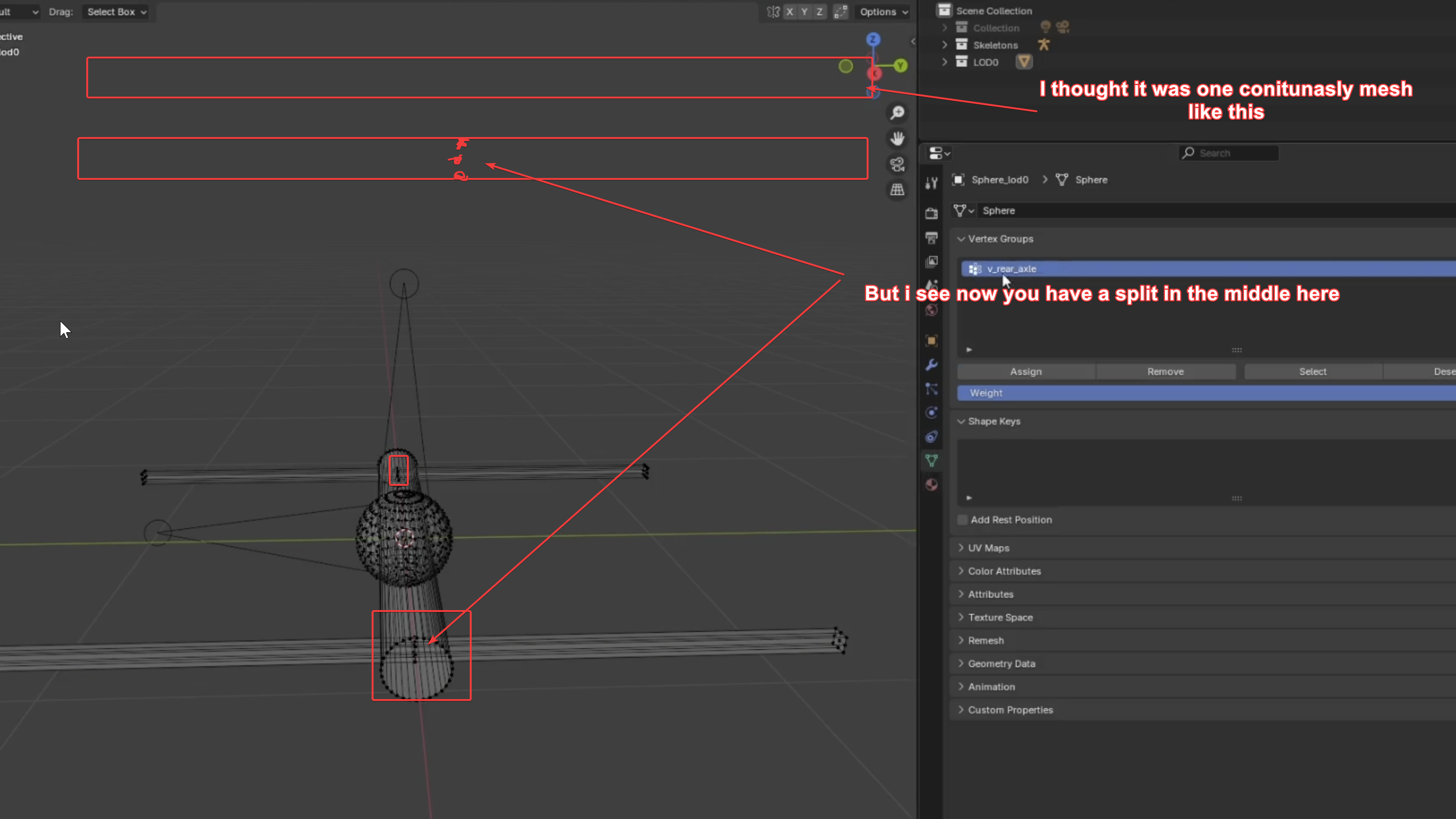 fallow pond
cant bend a box with only 8 verts
fierce kraken
How many LOD's is the "rule of thumb" as it were? I usually do LOD0-4 using the decimate modifier in blender.
hoary gazelle
fallow pond
cant bend a box with only 8 verts
my confusion stems from not having to use pose mode a lot with weight painting. For once i thought that merging the meshes ctrl J made it a true solid, but it dosnt, You gotta do boolean merge or remesh it.
hoary gazelle
ancient walrus
I’ll make video tomorrow no problem I always forget to show it lol
but also ive made a little blender tool here if youd like to check it out since i see you dont have it can for example do what you showcased just a little faster by one button click connecting a bone with vertex group on selected https://discord.com/channels/105462288051380224/1472408285192650834
hoary gazelle
ive made a weight plugin and its out now, small showcase here
surreal ore
It's almost like I was right the whole time huh? lol
ancient walrus
hoary gazelle
ive made a weight plugin and its out now, small showcase here
Brilliant pal that will be very useful 🙂
 thick cloak
hoary gazelle
ive made a weight plugin and its out now, small showcase here
thick cloak
hoary gazelle
ive made a weight plugin and its out now, small showcase here
When you release this
ancient walrus
It’s in the plugin channel he linked it above
hoary gazelle
thick cloak
When you release this
Its out now
 storm ermine
I'm giving away this model if anyone has ideas for it's usage. Made with blender, textured with substance painter, rigged.

Made this model for a game that I never finished. - Bofors 40mm stationary cannon (AC-130 variant) - Download Free 3D model by matasfizz
sly bridge
storm ermine
I'm giving away this model if anyone has ideas for it's usage. Made with blender...
is it a model you made?
storm ermine
sly bridge
is it a model you made?
yes
storm ermine
sly bridge
is it a model you made?
Also have a 105mm howitzer (also stationary for AC-130) but that one is not textured and not rigged, only prepared for texturing (high poly already modeled) if you're interested
 sly bridge
storm ermine
Also have a 105mm howitzer (also stationary for AC-130) but that one is not text...
sly bridge
storm ermine
Also have a 105mm howitzer (also stationary for AC-130) but that one is not text...
not directly interested, just making sure you are giving a way a model you have full rights over. Thanks for clarifying
hoary gazelle
surreal ore
It's almost like I was right the whole time huh? lol
not sure how i missed your message but i did, yes you wore correct indeed
surreal ore
I think you guys were just too involved to even realize anyone else even existed lol
Just so you know, spring suspension should be weighted the same way, except with a vertical gradient.
hoary gazelle
surreal ore
Just so you know, spring suspension should be weighted the same way, except with...
in the latest version there is an option to change the axis
 surreal ore
Nice!
hoary gazelle
surreal ore
Nice!
Any feedback greatly appreciated if you ever have the time to try them out 😄 https://discord.com/channels/105462288051380224/1472408285192650834
ancient walrus
hoary gazelle
Any feedback greatly appreciated if you ever have the time to try them out 😄 ht...
works nice pal cheers , i wasnt gonna reweight the arms but its easier now 😉
hoary gazelle
ancient walrus
works nice pal cheers , i wasnt gonna reweight the arms but its easier now 😉
niceee
also new update is out more options
ancient walrus
yeah i see the post i will check it out time for a break im all vehicled out LuL
 inner torrent
The work may not be complete but just to give you an idea, could this suspension system without weight painting could it work by setting the correct name of the guidelines of the vehicle parts_?
surreal ore
inner torrent
The work may not be complete but just to give you an idea, could this suspension...
What?
Not sure exactly what you're asking, but for anything to be animated it needs to weighted to some bone.
 faint turtle
Learning assets with a Balaclava. How to go about making the inside layer transparent? Done through texturing or a visibility setting within a workshop component?

 faint turtle
Ended up being a solidifier mod from blender. thanks though
inner torrent
surreal ore
Not sure exactly what you're asking, but for anything to be animated it needs to...
Ok thanks, I apologize sometimes I write with google translation to be quick and it is never precise with what I want to say
balmy coyote
about the mag again - where should i put the empty magazine xob model? because i dont see any reference to it anywhere
ancient walrus
inner torrent
The work may not be complete but just to give you an idea, could this suspension...
I would look at s105 it uses the animgraph linked to procedural rather than older uaz set up (unless it’s updated lately ) or similar . Rotator is the lead iirc but looking at the xob and s105 .aw in the anim editor use vehicle .agr in the list this will give you good nomenclature and weight ideas when ref skeleton
If you look just above you can see some video that example how to see in game editor and test before even config
What ya need to remember is that all vehicles may use different Skelton names so make sure you have started from fresh or followed the names in the skeleton on the vehicle you will duplicate or base yours on
This is not a tutorial but hope it gives some insight

Hi All
a few folks asked me what my biggest incentive was for messing with games and addons so i made this vid to explain how easy it is to get a return on reforger
inner torrent
ancient walrus
I would look at s105 it uses the animgraph linked to procedural rather than olde...
thanks mate i will do it, i m learning and try to get more info as possible and obtain a work as realistic as possible, and this is also thanks to you as community
 tender oracle
ancient walrus
This is not a tutorial but hope it gives some insight
https://youtu.be/FgKmh6W...
tender oracle
ancient walrus
This is not a tutorial but hope it gives some insight
https://youtu.be/FgKmh6W...
Best video i ever seen
fickle vigil
Making a GM placeable that will have a river. Is this possible and what is required so that water, bsp and boxvol move with the placeable if moved after placing? Would I just need an armature with river, bsp and boxvol parented to? Thanks in advance
 woven thistle
can anyone give me pointers why this model imports with the aqua and cyan color but in blnder i dont see anything wrong all the faces are blue so i dont understadn why its like this
 surreal ore
woven thistle
can anyone give me pointers why this model imports with the aqua and cyan color ...
surreal ore
woven thistle
can anyone give me pointers why this model imports with the aqua and cyan color ...
Vertex painting
woven thistle
surreal ore
Vertex painting
thank you i have been stuck on that for a while lol
 last hill
ancient walrus
This is not a tutorial but hope it gives some insight
https://youtu.be/FgKmh6W...
last hill
ancient walrus
This is not a tutorial but hope it gives some insight
https://youtu.be/FgKmh6W...
I had no idea that a video, on why you do what you do, could make me cackle like I did when you got to the car audio voice recording tweaking..
ancient walrus
The camera rolled the idiot danced lol 🙂
fierce kraken
Is there some kind of trick to assigning bones to an object for clothes? I can only ever get 4 bones assigned.
Edit: I got 8 bones to assign now, but 2 just won't, they are inside the weighted area they just wont assign.
Edit2: Is it a solidfy issue?
Edit3: Now the mesh is shrinking when the character moves.
brisk grotto
fierce kraken
Is there some kind of trick to assigning bones to an object for clothes? I can o...
Best approach is to use the character reference template and transfer weights. It’s never perfect but gets you close to the right positions to tweak the weights
ancient walrus
fierce kraken
Is there some kind of trick to assigning bones to an object for clothes? I can o...
Not done a lot of uniforms etc but make sure the modifier is attached to the mesh ie the spanner icon is in the mix and reset scale transform with ctrl +a
storm ermine
Looks like the origin is way below the actual model
woven thistle
storm ermine
Looks like the origin is way below the actual model
in blender its center of the truck
surreal ore
fierce kraken
Is there some kind of trick to assigning bones to an object for clothes? I can o...
Edit: Not sure the issue, Edit2: You should not be solidifying clothing, Edit3: This happens when you have more than one bone effecting a vert/verts.
worn plover
i have reimported like several times now. what am i missing. i had fixed this yesterday but now my ucl is flipped again all my transforms are applied in blender. ive closed and reopend workbench ive completly deleted all files from workbench and reimported.


nvm for some reason this time when i applied rotation it didnt want to accept it. so i just decided to NOT apply rotation and that fixed it i guess.
tepid cloak
ish shy
 shell hedge
Show wireframe
tepid cloak

just some geo nodes instanced as mesh could be alot less but this looked pretty good and wasnt cause any issues so far
chrome crater
Finally its done and works well. Just one tiny problem🥲 the boots are nearly black in white phosphore nightvision. I dunno how to fix that🥴
https://reforger.armaplatform.com/workshop/687D0ACCB444EE69-Wookie_Ghillieboots


Arma Reforger
Ghillie-covered combat boots designed for improved camouflage and immersion.
tepid cloak
sick love to see how youve done this if not similar to above lol
 upper idol
Can someone help me out with the opacity map in enfusion. For some reason the opacity isnt taking from substance painter. Thanks in advance!
sly bridge
upper idol
Can someone help me out with the opacity map in enfusion. For some reason the op...
what do you mean it is not taking from substance?
 brisk grotto
upper idol
Can someone help me out with the opacity map in enfusion. For some reason the op...
brisk grotto
upper idol
Can someone help me out with the opacity map in enfusion. For some reason the op...
Which export template are you using? The default ones dont export transparency
 brisk grotto
no which export template
upper idol
 sly bridge
not how the maps are used for the textures
upper idol
yea cant find info for it glad you can help
sly bridge
there is an export profile pinned into #enfusion_texture channel
brisk grotto
Or the ones in git here https://github.com/BohemiaInteractive/Arma-Reforger-Misc/tree/main/Art/Substance Export Profiles

GitHub
Additional resources for Arma Reforger modders. Contribute to BohemiaInteractive/Arma-Reforger-Misc development by creating an account on GitHub.
sly bridge
i also suggest you have a look over how each map is used in the texture RGBA channels
sly bridge
brisk grotto
Or the ones in git here https://github.com/BohemiaInteractive/Arma-Reforger-Misc...
afaik this link is also pinned there
brisk grotto
These are some additional ones I made that are on that git as pull requests. (A) is just alpha mask, BCA is BCR but alpha mask in it
upper idol
brisk grotto
These are some additional ones I made that are on that git as pull requests. (A)...
ok so opacity or opague is used as alpha 0 or 1?
brisk grotto
just put opacity so it's correct in substance, then use those export presets I sent, they will export it greyscale correctly for you
sly bridge
upper idol
ok so opacity or opague is used as alpha 0 or 1?
no it it has 255 greyscale values
brisk grotto
I'd suggest do your BCR as normal (with their main export templates) then export a _A with mine
I've found _BCA a bit fiddly sometimes
sly bridge
actually ideally there should be a single export profile that would also include emission as well which i have someplace
upper idol
lol
brisk grotto
sly bridge
actually ideally there should be a single export profile that would also include...
I made one for myself but I always have to untick the ones I dont want so it's a bit messy for noobs
sly bridge
brisk grotto
I made one for myself but I always have to untick the ones I dont want so it's a...
yeah have one myself no worries
brisk grotto
in about 20 years maybe someone in BI will notice the push request on the misc git I put in to add more
upper idol
@pufu the reforger bcr nmo a em is all i need right?
brisk grotto
you only need _EM if you have an emissive you want
sly bridge
upper idol
@pufu the reforger bcr nmo a em is all i need right?
yes
even if you don’t have emissions set it will export black
upper idol
thank you guys! i am new to enfusion so its alot to get used too
brisk grotto
As standard practice always go for _BCR and _NMO, if you want transparency add a _A, if you need emmisive add an _EM
Once you export your _A you will need to add the mask to your material for it to work
and change the alpha mode
upper idol
add user alpha?
brisk grotto
The opacity mask bit there

Add the _A to that

And in general further down change blend mode
to alphablend
if you dont it wont check for the alpha mask
upper idol
thank you man
@brisk grotto is there a way to turn it up to see the material better
its like transparent
brisk grotto
dont think so, as long as it looks fine in substance and you use the export templates you should be fine once you get to workbench

 brisk grotto
So play with the alpha settings, the multi slider above, or change the culling type etc
it's a bit of a messy thing sometimes
 brisk grotto
 upper idol
thanks buddy saved me tons of time and aggrevation !
brisk grotto
I've been there so happy to help lol
upper idol
@brisk grotto hey what makes structures enterable in reforger
brisk grotto
WDYM? If you just mean if you can walk into it or not its colliders
upper idol
for example it you put a collider on it the building will become a box that you cant eneter?
brisk grotto
The collider stops people/vehicles/bullets so yeah whatever shape you makes it will block
upper idol
roger that thanks again
 mortal abyss
Hi! Is it possible to create a new mesh out of two already existing ones? If I have two "generic entities" with meshobjects, it is possible to merge those into a single new one? (Sorry if wrong channel)
steel hare
You mean you got two xob / fbx files which you combine into one in the World Editor?
mortal abyss
Yeah something like that if it's a thing! Basically imagine a bunch of demo charges glued together, currently using slots but if I could just have a single mesh then I'd guess less to go wrong?
 formal parcel
When modelling a vehicle the polygon count is significantly greater than the minimum for implementing how do I adjust
sly bridge
formal parcel
When modelling a vehicle the polygon count is significantly greater than the min...
why is the polycount higher? just optimize your it down (generally rounded / spherical parts take more polycount)
formal parcel
It’s a high render of a leo chassis
sly bridge
formal parcel
It’s a high render of a leo chassis
render?
formal parcel
When I try to optimize it it messes up the grenade launchers get messed up
sly bridge
When modeling a whatever from scratch, you are the only one in control of the polycount, and you can adjust these as you deem necesary
sly bridge
formal parcel
When I try to optimize it it messes up the grenade launchers get messed up
how so?
formal parcel
They become cones
sly bridge
formal parcel
They become cones
are you working on your own model or are you trying to optimize/ decimate an existing model made by someone else
formal parcel
originally it was an stl file made by someone else
sly bridge
so not yours, and most likely triangulated....
formal parcel
Yes
sly bridge
anyways, there are a huge number of ways to go about reducing polycounts, depending on the software use and method chosen (automated / semi-automated and/or manual).
I would suggest having a looky over tutorials for your prefered software to understand what can/needs to be done
When modelling a vehicle the polygon count is significantly greater
This is what got me confused, because you weren't actually modelling a vehicle yourself
formal parcel
Gotcha
formal parcel
sly bridge
anyways, there are a huge number of ways to go about reducing polycounts, depend...
What do you do to reduce poly?
sly bridge
formal parcel
What do you do to reduce poly?
i model my game assets with a budget in mind
formal parcel
thanks
 topaz smelt
What’s the best way to fit clothing onto the sample model? Surely sculpting isn’t my best option? Any addons I should be using?
compact scarab
topaz smelt
What’s the best way to fit clothing onto the sample model? Surely sculpting isn’...
Shrinkwrap modifier is one technique
storm ermine
topaz smelt
What’s the best way to fit clothing onto the sample model? Surely sculpting isn’...
I haven't dont any cloth modeling but this seems like a good way to start https://www.youtube.com/watch?v=28tYKUH66KA

In this simple tutorial, you will learn how to do cloth sewing in Blender 4.0.
More content:
Join The Patreon: https://www.patreon.com/PIXXO3D
Skillshare Free For A Month: https://skl.sh/3aROa69
Social:
Join The Discord Server: https://discord.gg/YntmGXtuCP
Instagram: https://www.instagram.com/pixx...
sly bridge
topaz smelt
What’s the best way to fit clothing onto the sample model? Surely sculpting isn’...
made from scratch or acquired/purchased?
topaz smelt
sly bridge
made from scratch or acquired/purchased?
Either or. I haven't tried creating clothes via sewing but more than likely purchased ones I want to use.
sly bridge
i have never done it with other’s people models, in general from scratch you model on top of an existing geometry (the character’s sample).
However, depending on the software use, there are different tools to do that. Most are called conform / wrap / skinwrap etc. It is a mix of automated and manual work
example for the software i use - https://www.youtube.com/watch?v=fgKhMXJbn4E

Become a member to show your support.
https://www.youtube.com/channel/UC-HJyEfrDmRuZn8pqZuRzJw/join
Hey guys!
In today's video I will introduce you to the new Conform in 3ds Max.
Fala pessoal tudo bom com vocês?
No video de hoje eu vou apresentar para vocês o novo Conform no 3ds Max.
#3dsmax #hardsurface #boolean #tutorial #tips #new3dsm...
topaz smelt
Yeah i'm using blender. Used skrink wrap before just found it a bit funky doesn't fit the character properly then using the scuplt mode just doesn't look right after some edits
compact scarab
topaz smelt
Yeah i'm using blender. Used skrink wrap before just found it a bit funky doesn'...
Also seen people use inflate and then shrinkwrap after I think
combining techniques
topaz smelt
compact scarab
Also seen people use inflate and then shrinkwrap after I think
Noted, will definitely give it a try
Thx
 feral jolt
Hello, I see it was not shared in this channel yet so here it is: a wiki article regarding model performance
https://community.bistudio.com/wiki/Arma_Reforger:Model_Performance
wicked dirge
feral jolt
Hello, I see it was not shared in this channel yet so here it is: a wiki article...
Would be good if you add values for different type of vehicles as well (helicopter, armored etc.)
feral jolt
ah yes, I wanted to add helicopters and BTR
feral jolt
wicked dirge
Would be good if you add values for different type of vehicles as well (helicopt...
added!
 feral jolt
Hello, I see it was not shared in this channel yet so here it is: a wiki article...
feral jolt
feral jolt
Hello, I see it was not shared in this channel yet so here it is: a wiki article...
 graceful frigate
I've bones in my model when i export the FBX it doesnt show the bones in enfusion
sly bridge
graceful frigate
I've bones in my model when i export the FBX it doesnt show the bones in enfusio...
open importer window, make sure bones are ticked and reimport asset
graceful frigate
sly bridge
open importer window, make sure bones are ticked and reimport asset
thanks your a legend
 untold glacier
topaz smelt
Noted, will definitely give it a try
untold glacier
topaz smelt
Noted, will definitely give it a try
Not sure if it’s the most efficient way but I will get the torso lined up, go into sculpt, box select mask the torso so it isn’t effected by the sculpting, then I will use a mixture of elastic grab and pose tools to get the arms where I want them, I use pose for moving the arms then elastic grab for micro adjustments
 mellow urchin
Question... Whats the amount of faces on a pastg vest model in vanilla arma? Anyone know?
stray bridge
mellow urchin
Question... Whats the amount of faces on a pastg vest model in vanilla arma? Any...
you can check, just check out lod0
 eternal jewel
Trying to make a custom armor vest with vanilla PASGT as a base, however the armor value does not seem to work.
I used the same firegeo as vanilla PASGT. However, characters wearing it gets incapacitated from just 2 shots of 9mm. It also shows blood particles even if the shot is on the vest.

2 shots of 9mm mirrors characters without vests so its obvious the vest isnt working properly.
 main shoal
Does anyone know how I can weight paint a plate carrier to be like completely rigid like the RHS vests?
stray bridge
i dont know the rhs stuff and obv i dont know what ur model looks like but you might get away with just fully set paint on spine5
 rare rover
Does anyone know what is a good way to start making modded gear? As I probably don’t have time to really learn blender too much but would love to create some gear and stuff for both factions
main shoal
stray bridge
i dont know the rhs stuff and obv i dont know what ur model looks like but you m...
My model is just like a generic MBAV vest. I tried that earlier but it makes my vest off set by quite a bit, do I need to have all the vertex groups because I deleted every single one except spine 5
untold glacier
eternal jewel
The collider materials and the armor damage manager in the prefab are what set this iirc
eternal jewel
untold glacier
The collider materials and the armor damage manager in the prefab are what set t...
in the image you replied to, you can see that the collider is aramid 6.5mm. This is the same that is used in the vanilla PASGT.
I have not changed anything from the SCR_ArmorDamageManagerComponent of the prefab as well, it is still the same as vanilla except the adding my own colliders to it in the Additional Hitzones section
untold glacier
Maybe you got super beretta.
ancient walrus
rare rover
Does anyone know what is a good way to start making modded gear? As I probably d...
Probably weight it to a central part of the torso like spine 2 or 3 ?
fierce kraken
Is this collider registering as Invalid because they are not connected? Edit: I separated them and reimported and they registered, so I do believe that was the case.

 patent flower
Anyone here use 3dsMax to make their models? im looking for some help how to do the layer presets via the parameter editor. any help much appricated
sly bridge
patent flower
Anyone here use 3dsMax to make their models? im looking for some help how to do ...
shoot
patent flower
 patent flower
sly bridge
shoot
patent flower
sly bridge
shoot
Hi PuFu, Iv got to this stage ^^ what ever iv tried dosent seem to work, how do i need to set this up to transfer properly
sly bridge
patent flower
on phone so please explain what you wanna achieve
transfer to enfusion?
patent flower
yeah i want to be able to add the layer presets to the coliders like its documented for blender
 brisk grotto
fierce kraken
Is this collider registering as Invalid because they are not connected? Edit: I ...
brisk grotto
fierce kraken
Is this collider registering as Invalid because they are not connected? Edit: I ...
Did you import it as a UTM before you separated?
fierce kraken
brisk grotto
Did you import it as a UTM before you separated?
No, I imported as a UCL_ because they were cylinders.
brisk grotto
fierce kraken
No, I imported as a UCL_ because they were cylinders.
You can only do UCL, UBX etc if it’s a single cylinder or cube. It can’t contain multiple
So you either make it UTM or you separate them each cylinder so it treated them as two
sly bridge
patent flower
yeah i want to be able to add the layer presets to the coliders like its documen...
never done it that way will test later on today
sly bridge
patent flower
basically -> Object's base level -> Parameter Tupe : String / Name of Parameter : usage (CA def version number auto-update and Add Presets Options unticked)


or whatever other parameter you want from this page
https://community.bistudio.com/wiki/Arma_Reforger:Collision_Layer
Important, the name of the parameter needs to be usage
patent flower
sly bridge
or whatever other parameter you want from this page
https://community.bistudio.c...
Thanks PuFu much appreciated, will try it out tonight when I’m back from work!
sly bridge
patent flower
Thanks PuFu much appreciated, will try it out tonight when I’m back from work!
no worries, took more time because usage was eluding in terms of mandatory thing
 sly bridge
- it is a string parameter
- its name is "usage" and in value are/will be all defined usages like this: "FireGeo" (only for detection of bullet impacts in this case) and possible others
- if a collider shape has no usage parameter, then it collides (simulates) in every layer and warning message will appear in console log
- for creating custom attributes in 3ds Max, use only the Parameter editor in Animation menu, otherwise the properties in exported FBX can't be edited in Maya. So doing it with Object Properties/User defined is FORBIDDEN```@fossil crater / @feral jolt is it possible to detail how can (for colliders) set game materials for instance. I would assume it is also some string parameter
compact scarab
sly bridge
<@272245679013888011> / <@137855151120711680> is it possible to detail how can (...
Use enfusuon blender tools plugin. Select your colliders and open the materials section in the enfusion tab, and click colliders. Make sure workbench is open.
The colliders button will only be ungosted if the colliders have the correct prefixes
sly bridge
compact scarab
Use enfusuon blender tools plugin. Select your colliders and open the materials...
i don't wanna use blender, which is the point of the above question
compact scarab
sly bridge
i don't wanna use blender, which is the point of the above question
Lol my bad
shell hedge
All you need to do is use the GUID of the material as the material name of the collider, as seen in sample models
Either GUID or ResourceName dont remember
sonic tree
guid
sly bridge
shell hedge
All you need to do is use the GUID of the material as the material name of the c...
you sure ?

nvm it is ResourceName indeed @sonic tree
tnx
sonic tree
i thought it was guid mb
formal parcel
Hey, I have a tank that I want to model into reforger. it has a high triangle count at the moment and I have some gaps in the track system and the chasis. I am curious if when I start to set it up in enfusion that it wont just blunder its self and I need to keep going.
 mighty bronze
formal parcel
Hey, I have a tank that I want to model into reforger. it has a high triangle co...
mighty bronze
formal parcel
Hey, I have a tank that I want to model into reforger. it has a high triangle co...
How high of a polycount we talking
and where did ya get it
formal parcel
mighty bronze
How high of a polycount we talking
*and where did ya get it*
300k and it originally was an stl file
It used to be 4m
I put on my own set of tracks so I could animate it
mighty bronze
Hmm
mighty bronze
formal parcel
300k and it originally was an stl file
I know stl files tend not be optimized for video game use at all
And id verify the license wirh that model to be something like royalty free or Commons attribution.
Got a link?
formal parcel

Cults 3D
The Bergepanzer 3 Buffel armored recovery vehicle was developed by Rheinmetall. It is based on the Leopard 2 chassis and is fitted with powerful recovery system.
The Bergepanzer 3 is fitted with a crane, winch and front-mounted dozer. The main mission of the Buffel is recovery of damaged, overturned and swamped main battle tanks and other tracke...
mighty bronze
formal parcel
https://cults3d.com/en/3d-model/game/bergepanzer-3-buffel
Oh man that's a bad, I hope you havent poured hours into this yet
formal parcel
Elaborate
mighty bronze
CULTS - PU private use license
"This license does not include permissions: for selling, distribution, sharing, donation, exchanging, copying, modifying or adapting the 3d model"
Now
Im not a lawyer
But this sounds like a stricter version of editorial use
And AFAIK, using models in a mod that gets distributed isn't private use
formal parcel
Damn
I have other ones that are non licensed that I can use this was just the most detailed
mighty bronze
Non licensed?
mighty bronze
k that's probably better, would still see how to best make sure you get written agreement for the use of thise models
 obsidian grail
first time 3d scanning shoes
600 vertices
gonna import them soon 🙃


 twin kraken
obsidian grail
first time 3d scanning shoes
600 vertices
gonna import them soon 🙃
twin kraken
obsidian grail
first time 3d scanning shoes
600 vertices
gonna import them soon 🙃
what did you use to 3d scan?
main shoal
obsidian grail
first time 3d scanning shoes
600 vertices
gonna import them soon 🙃
Shi I gotta port my Air Force’s
 broken topaz
I have a Machine gun that has been setup using the M16 prefab (as it needed a suppressor and I couldn't get it working with the M60 prefab), I can confirm everything works fine with the M60 prefab but when I have copied everything over to a M16 prefab the mounted position of the weapon seems off, see image, how do I change the offset on where the model gets mounted. The pivot point seems to be under the center of the gun causing it to sit next to the players head. Is there a way to move the pivot point and make the weapon sit further forward? Someone else suggested AimingModifierAttributes but I havent been able to get this working
 last hill
broken topaz
I have a Machine gun that has been setup using the M16 prefab (as it needed a su...
last hill
broken topaz
I have a Machine gun that has been setup using the M16 prefab (as it needed a su...
There are prefab settings for position of pivot etc. Off the top of my head I can't recall where but somewhere inside the aimingmodifier is a deployed pivot position pointinfo section you need to configure.
 warm oak
How many uv sets can the engine handle per model like max limit?
 merry rivet
Question:
bevel edges for 3D environment assets:
Only keeping them in the Highpoly and baking them into the LOD0 or giving the assets an existing bevel edge in LOD0?
 haughty knoll
merry rivet
Question:
bevel edges for 3D environment assets:
Only keeping them in the Highpo...
haughty knoll
merry rivet
Question:
bevel edges for 3D environment assets:
Only keeping them in the Highpo...
Have a look at similar vanilla assets in workbench. The houses have beveled edges at every window- and doorframe hole for example.
 hazy path
warm oak
How many uv sets can the engine handle per model like max limit?
hazy path
warm oak
How many uv sets can the engine handle per model like max limit?
i believe its only 2
warm oak
hazy path
i believe its only 2
Ah OK that sucks to be honest but I can see If it works
hazy path
warm oak
Ah OK that sucks to be honest but I can see If it works
you can use multimat if you need to have multiple materials on one object
warm oak
hazy path
you can use multimat if you need to have multiple materials on one object
To be honest I have no idea what that is I'm trying to figure this out so my devs don't make mistakes
merry rivet
haughty knoll
Have a look at similar vanilla assets in workbench. The houses have beveled edge...
Yeah.. good idea.. I'll have a look...
obsidian grail
twin kraken
what did you use to 3d scan?
this 🙃
 merry rivet
haughty knoll
Have a look at similar vanilla assets in workbench. The houses have beveled edge...
merry rivet
haughty knoll
Have a look at similar vanilla assets in workbench. The houses have beveled edge...
Okay, yeah, they use bevel edges on most environment items
mighty bronze
obsidian grail
this 🙃
I could buy an M2 Carl gustsf for the price of that thing

 white garden
Is it possible to make a LOD setup to where the closer you get to something it disappears? I want to make a city landscape that disappears as you get closer to the city to make it look bigger.
 noble ravine
maybe make the lod with no mesh?
twin kraken
obsidian grail
this 🙃
How much was that John
main shoal
can someone help me out? im trying to make a belt where the actual belt is just fully rigid but this dangling bungee cord follows the leg
 obsidian grail
twin kraken
How much was that John
obsidian grail
twin kraken
How much was that John
2.5k
my first ever 3d scan not played with any settings or software stuff so it's not the best but it looks okay for first time ig
 normal field
hi, can someone explain to me how to add an helmet inventory ? like to add stuff to the helmet itself like a cover or smth ?
I'm new to reforger modding
mighty bronze
with?
formal parcel
That model
I got permission from the creator
How do I get the tracks to not be transparent on the vehicle
mighty bronze
sorry I'm really tired rn
maybe check to make sure they're MatPBRBasic in the materials?
Also in blender check for inverted normals/faces
formal parcel
Thanks
mighty bronze
if you're not sure where face orientation option is

and proper _BCR and _NMO for their respective textures
Uh
unless you are using transparency... which I've only messed with glass for transparency
urban needle
Hey everyone, any ideas for making this revolving door work? Maybe it doesn't need to be opened manually, but just kept rotating continuously.
 brisk grotto
merry rivet
Question:
bevel edges for 3D environment assets:
Only keeping them in the Highpo...
brisk grotto
merry rivet
Question:
bevel edges for 3D environment assets:
Only keeping them in the Highpo...
Is Henry planning drone strikes? Weird ass crossover to see you here 💀
brisk grotto
urban needle
Hey everyone, any ideas for making this revolving door work? Maybe it doesn't ne...
You'd likely have to look at procedural animations. You can set them up to rotate/translate off specific bones then define a trigger (e.g a button for a roller door) or time or whatever
merry rivet
brisk grotto
Is Henry planning drone strikes? Weird ass crossover to see you here 💀
I'm working on an Arma mod as a hobby 😄
main shoal
Are there programs that can just create a folded item variant for my clothes?
brisk grotto
main shoal
Are there programs that can just create a folded item variant for my clothes?
Not really no, especially since the folded model will be different depending on the type of worn clothing model in question.
There’s some tricks to make them quickly though like simulation in blender, or you re-use generic drop models
main shoal
brisk grotto
Not really no, especially since the folded model will be different depending on ...
Where could I start with that
The simulation
 odd goblet
main shoal
The simulation
odd goblet
main shoal
The simulation
just look up "blender cloth sim" there's a bunch of tutorials. if you do end up trying that, i'd recommend scaling your item up a bit before running the sim. the default cloth settings can make normal sized objects behave weird in my experience
if you want to save a ton of hassle though, just take a vanilla item model and swap the material to something close to your clothes. people don't really look closely at dropped clothing items on the ground
 main scaffold
Hi. Could you tell me if there are any more detailed guides for creating BSP? I've encountered an uneven roof. However, the vanilla models (example: Barn_E_01) solved my problem. The guides on the bistudio website don't cover BSP in detail, and the example provided is very basic, without player access to the roof.
signal gull
How should I approach crating a model with texture variations? For my map I want to create a bus stop with 3 different sets of ads placed on the sides. My first idea was to have the bus stop reference two materials - one for the bus stop itself and one for the ads where I would put all variations on one texture and create three models with different uv mapping. But this seems too unoptimised as it requires three different models to be created. Is there a better solution?
urban needle
brisk grotto
You'd likely have to look at procedural animations. You can set them up to rotat...
Ok, thank you very much
brisk grotto
signal gull
How should I approach crating a model with texture variations? For my map I want...
Personally I'd do one model, two materials. Stick your ads on the second material (all of them), on the material variants for your ads you can go to this section and add a UV offset in-engine to push it along to your next set of ads, you'd just have to play about with a texture layout that makes sense with that.

Then just overwrite the ad material for each prefab variant
If you do the bus stop material right you can also add colour variants of the bus stop itself as you go
signal gull
brisk grotto
Personally I'd do one model, two materials. Stick your ads on the second materia...
Oh, perfect! This is literally perfect for my purpose. Thanks!
 drowsy mason
Hey - made a mod and put it in workshop... when I play with friends multiplayer PVE, the items show up for me but not for them... I'm guessing there is a component that activates them in multiplayer??
 calm isle
What is the max distance I can extend a model's lods out until it disappears? I've got some models that will just be completely gone after 25 meters or so
calm isle
Like this is how far away I am before it disappears entirely

 worn plover
drowsy mason
Hey - made a mod and put it in workshop... when I play with friends multiplayer ...
worn plover
drowsy mason
Hey - made a mod and put it in workshop... when I play with friends multiplayer ...
Post a screenshot of an item show the components list also try to explain what you mean by they show up for you but not for them.
worn plover
calm isle
Like this is how far away I am before it disappears entirely
How many lods does it have?
If it's really tiny it might be a pixel size thing. But don't quote me I'm not sure.
Try looking at a similar size object and see how the lods etc are set up
mortal abyss
Any resources on how to import textures/materials from blender? Got a model in but so lost with getting the rest in!!
calm isle
worn plover
How many lods does it have?
I've tried using one LOD that holds over as well as up to 11 LODs. It's about the size of a hand so the size could be an issue
worn plover
calm isle
I've tried using one LOD that holds over as well as up to 11 LODs. It's about th...
how are grenades set up? or ap mines? they are about the same size
calm isle
worn plover
how are grenades set up? or ap mines? they are about the same size
That's a good point, I'll take another look at those today but I also feel like it's equally likely it's some setting I'm missing somewhere
worn plover
calm isle
That's a good point, I'll take another look at those today but I also feel like ...
i dont remember if you have to do something with mipmaps either
ill have to look again
 final vector
Can anyone provide input on creating _Delated models for jackets?
worn plover
Deflated* models are usually just compressed around the waste and or chest area so when they go under a vest or pants are put on or sometimes a backpack they don't clip. What program are you using? I used marvelous for clothing and did by a mixture of stretch weft and/or that pressure mechanic they have. If your doing it in blender I'm not quite positive on the best way.
final vector
Blender
I figured that was the case I’m curious if I can get that same effect just molding the models closer to the body?
worn plover
Might be able to get cheeky with a targeted light shrinkwrap I dunno.
final vector
Hmm I’m getting closer I used a cloth filer and went into the negatives under inflate. It’s pretty finicky
worn plover
Yea you for sure could mold them closer. I'm no artist so I try to stick to the least manual way possible
final vector
I feel ya on that.
It’s a lot of work to get everything done how BI does but I really want the best for this mod
It would be hella easier if I had the vanilla assets in blender to sculpt around
worn plover
take a look at the animation model.
i stole the boot shape off of that and used it as a prop when i was doing pants.
inner torrent
Hi everyone,
I’m having an issue when exporting a model from Blender to the tool
In Blender I positioned the steering system correctly using an armature (bones). Everything looks correct in Blender: the steering wheel and linkage are in the right position.
However, when I export the model as FBX and import it into the tool, the steering parts are no longer in the position I set. It looks like enfusion is ignoring the pose and importing the mesh in a different position .
What I need is for the steering to stay exactly in the posed position I set in Blender.
Does anyone know the correct workflow for exporting posed models from Blender to the tool?
Thanks in advance for any help!

 worn plover
are you applying transforms?
sonic tree
apply transforms
 plush torrent
inner torrent
Hi everyone,
I’m having an issue when exporting a model from Blender to the tool...
plush torrent
inner torrent
Hi everyone,
I’m having an issue when exporting a model from Blender to the tool...
apply transforms to the model in blender
worn plover
Maybe he didn't hear us. HEY DID YOU APPLY TRANSFORMS?
inner torrent
Good morning guys, I have already applied the transformation (ctrl+a ->> apply all tranform) but now the vehicle in the blender viewport is in its right place and on enfusion the vehicle is at a height and distance that does not correspond to the v_root
 worn plover
inner torrent
Good morning guys, I have already applied the transformation (ctrl+a ->> apply a...
worn plover
inner torrent
Good morning guys, I have already applied the transformation (ctrl+a ->> apply a...
I had this issue with colliders on wheels I ended up not applying rotation. And it seemed to fix it. But the issue might be because transforms is applied to the model and the armature? And the bones in the armature are very sensitive to location and rotation. I could be completely wrong here. I would check the sample vehicle mod we've been provided against yours to spot the difference.
 wide yew
Would it be possible to add custom a custom apartment building and its own destruction variant or is the destruction thing always the same
brisk grotto
wide yew
Would it be possible to add custom a custom apartment building and its own dest...
You can add custom destruction models and stages to your prefabs same way as base game buildings you’d just need the differed FBX for each stage you want to show
urban needle
ty
sly bridge
@urban needle wrong channel
patent flower
Hi all got another question, what would cause part of my model to import with darker colour

should be all white like the suspension
when i apply materials its making them darker
 fluid dragon
patent flower
Hi all got another question, what would cause part of my model to import with da...
fluid dragon
patent flower
Hi all got another question, what would cause part of my model to import with da...
check if the vertex are painted somehow in blender thats a problem that i had once
sly bridge
patent flower
vertices paints /vertex colors
sly bridge
fluid dragon
check if the vertex are painted somehow in blender thats a problem that i had on...
he isn’t using blender, however the issue is most likely the same
fluid dragon
yeah, was just thinking that i had that problem in my blender file so i said it that way ^^
patent flower
That did the trick thanks for the help
 little trail
how do i edit texures for existing mods for example im dutch and i want to make dutch skins for vehicles
 snow pasture
little trail
how do i edit texures for existing mods for example im dutch and i want to make ...
snow pasture
little trail
how do i edit texures for existing mods for example im dutch and i want to make ...
You have to get access from those mod creators
little trail
snow pasture
You have to get access from those mod creators
is that the reason i cant get the pgn?
sly bridge
little trail
is that the reason i cant get the pgn?
can you be more specific about what you want to do?
little trail
like putting dutch flags on this model
 sly bridge
in general mods are all copyrighted material with an author. depending on the license file associated you can / cannot edit the files. However all files published are locked, you will not be able to extract any of it
little trail
and i need this pgn
 little trail
sly bridge
in general mods are all copyrighted material with an author. depending on the li...
little trail
sly bridge
in general mods are all copyrighted material with an author. depending on the li...
ahh okay
 white plover
anyone know to fix this issue
 calm rune
white plover
anyone know to fix this issue
calm rune
white plover
anyone know to fix this issue
100% weights on Spine5 and no other vertex group
Assuming that is a plate carrier.
 safe oxide
does anyone have a good tutorial on adding bones & collider for cars ?
 cold rune
white plover
anyone know to fix this issue
cold rune
white plover
anyone know to fix this issue
Click through the vertex's on the right arm and see if any spine bones are assigned to it and remove it.


 calm rune
white plover
calm rune
white plover
Delete them all except Spine5 and make the entire thing red
white plover
calm rune
Delete them all except Spine5 and make the entire thing red
Legand iv been fkin about with this for hours did not think it would be as simple at that
 tough junco
Don't if it's the right place for that, but i'm trying to make the Coalition VON Radios into RHS Gadget Slot. Seem like in the good slot so far but it is offset, any ideas ?
 mortal abyss
Why can't I download the Arma Reforger Substance Painter Export Profiles via Github?
brisk grotto
mortal abyss
Why can't I download the Arma Reforger Substance Painter Export Profiles via Git...
You should be able to, whats happening when you try?
mortal abyss
I can't open the files within github to access the download option! I guess it's an issue their end?
brisk grotto
mortal abyss
I can't open the files within github to access the download option! I guess it's...
Try this one? Download button top right

GitHub
Additional resources for Arma Reforger modders. Contribute to BohemiaInteractive/Arma-Reforger-Misc development by creating an account on GitHub.
 blazing zenith
Any ideas how to get rid of these placeholder textures? I've remapped the original textures of this model to be PNGs when the ones it came with were Bitmaps, i thought this would fix the problem but no.
I can see the actual material under this bright colours, so not sure why its still got the bright colours on the imported FBX
 sonic tree
blazing zenith
Any ideas how to get rid of these placeholder textures? I've remapped the origin...
sonic tree
blazing zenith
Any ideas how to get rid of these placeholder textures? I've remapped the origin...
color attributes in data
blazing zenith
sonic tree
color attributes in data
Vertex painting in Blender was the problem
sonic tree
or that yep
blazing zenith
Sorted now

 gloomy rose
little trail
like putting dutch flags on this model
gloomy rose
little trail
like putting dutch flags on this model
Ar you dutch me asswel!
Coolests
little trail
gloomy rose
Ar you dutch me asswel!
Lekkerman im still in the beginner phase but maybe we can make mods in the future
gloomy rose
little trail
Lekkerman im still in the beginner phase but maybe we can make mods in the futur...
Trouwens doe ik ook voor arma 3 en miss arma 4 overwrite ik gewoon die shit en plants ik me liverys er op
Als je die guy denk ik gewoon tagged voor de originele mod hoort er geen probleem te zijn denk ik
 nova sequoia
can someone import some of my assets for me
mortal abyss
Creating BCR'S and NMO's using Substance painter - Why do the edges of surfaces "bleed" onto others? Or you get edges between different materials showing no colour?
I am pretty new to modelling side so I could be missing something, but I am making sure all faces have a material assigned to then etc. But then am getting a load of nasty looking edges once applied to the .emat/.xob
remote palm
mortal abyss
Creating BCR'S and NMO's using Substance painter - Why do the edges of surfaces ...
Show a picture please. Might be vertex coloring
mortal abyss
remote palm
Show a picture please. Might be vertex coloring
I'll send some over when I'm back from work - So what is vertex colouring? For my learning lol
mortal abyss
remote palm
Show a picture please. Might be vertex coloring
Here are some examples of what I mean

 remote palm
That’s just bad baking / possible missing UVs
mortal abyss
Missing UV's?
This is after changing to 2048x2048 and changing "UV Padding" to UV Space Neighbour
 sly bridge
do you have UV splits there?
remote palm
The inside of the tubes look like they are not UV unwrapped to my eye.
But thats looking better already?
Mby also show the model in blender with the seams and the UV island?
mortal abyss
I'm sorry. What's a UV split? Google brings up a bunch of weather things
mortal abyss
remote palm
The inside of the tubes look like they are not UV unwrapped to my eye.
But thats...
Ya definitely getting there anyway - Here's a blender screenshot - AFAIK all faces (verticies?) have been unwrapped, I have heard that having too much space around the islands is bad practice though?
 remote palm
Screenshot of your model in edit mode?
sly bridge
mortal abyss
I'm sorry. What's a UV split? Google brings up a bunch of weather things
where there is a hard edge you are suppose to have a UV split (not just for baking purpose). Seems you have, you could also weld some of these UV islands into fewer (for everything that is cylinder)
mortal abyss
remote palm
Screenshot of your model in edit mode?
 mortal abyss
sly bridge
where there is a hard edge you are suppose to have a UV split (not just for baki...
mortal abyss
sly bridge
where there is a hard edge you are suppose to have a UV split (not just for baki...
By welding do you mean just moving those islands together, or is this some specific feature/tool to use? 🙂
sly bridge
mortal abyss
By welding do you mean just moving those islands together, or is this some speci...
i mean actually welding the vertices. i am not a blender user, so i am uncertain what tools you need to use.
sly bridge
mortal abyss
Here are some examples of what I mean
how does your HP looks like?
mortal abyss
What's an HP? I am a three-day blender user, so I too am uncertain on tools to use 😄 Will do some digging
sly bridge
mortal abyss
Here are some examples of what I mean
this looks like baking artefacts. substance is expecting you to also have a HP model for baking normal's map
mortal abyss
OHH as in high poly for the normal, low(er) for the texture itself? Thanks for the pointers
sly bridge
low poly is usually the game mesh. High poly is the mesh you bake normals from and other details directly into the textures


 mortal abyss
Thanks 🙂
sly bridge
mortal abyss
Thanks 🙂
no worries. Also as a general rule, get the geometry reduced the smaller it is. The external cylinder of the body can have higher counts, the ones inside can have lower counts. in my example - external is 64 faces, internals are 16 each, if i were to make that would most likely go down to 12 (get cylinders to subdive to 4 btw)
brisk grotto
nova sequoia
can someone import some of my assets for me
People are unlikely to do it for you, they can help answer questions to get yours in yourself but won’t do it all for you
nova sequoia
brisk grotto
People are unlikely to do it for you, they can help answer questions to get your...
ok
worn plover
nova sequoia
can someone import some of my assets for me
Depends on what they are
sly bridge
worn plover
Depends on what they are
helping yes. doing it, nope.
 olive fern
Hi, not sure if its the right channel but I have questions/ need help with my collider on my asset.
I made this room and the roof/ceiling is still wallbang-/penetrable by bullets and grenade explosions. I decided to put another angled square with concrete 100mm properties between ceiling and the upper floor but that didnt fix it neither.
Putting an actual concrete slab down in the engine works but it seems like an ugly work around.
 last hill
olive fern
Hi, not sure if its the right channel but I have questions/ need help with my co...
last hill
olive fern
Hi, not sure if its the right channel but I have questions/ need help with my co...
Likely wrong collider type, check what colliders are present in the concrete slab xob file in workbench then compare your collider type and settings
worn plover
sly bridge
helping yes. doing it, nope.
i mean if he made and has full rights to the assets and he wants to give them to me to upload im pretty sure thats fine. although i do feel the need to make a character statement here now and say that my intention is altruistic and not malign.
nova sequoia
worn plover
Depends on what they are
Just a table tool cubbies set
worn plover
just a prop? or are you trying to do something with it?
nova sequoia
Armory
Idk how to set up colliders or set up the bar maps metalness or hm with easy channel packing to
But everything is there for it just forgot how to import things
worn plover
what i mean is the asset simply meant to be a world prop?
like a table or chair or mailbox etc. props..
nova sequoia
No there going to be used to make a new arsenal prefab
worn plover
ahh
nova sequoia
Ik how to do that I just forgot how to import things
worn plover
post a pic of the model with the scene collection shown in blender so i know where to start.
worn plover
if you haven't made colliders its just a collection of meshes in the shape of your model given a prefix_name. This is what the vanilla arsenal uses. even though they tell us trimesh colliders are expensive they use them everywhere. but if can make your colliders with just a few simple shapes you should.
ill just post a quick and dirty rundown then
nova sequoia
I’ll be home at 3:20 I’ll send you what I mean then
worn plover
if you have the EnfusionBlenderTools plugin go to Add-> EBTobjects-> Colliders to see all the available options and to have it auto prefix. then in the plugin under material tools click colliders setup for the selected collider.
then just export to your workbench addon assets folder.
and set it up like you said you know how too
mortal abyss
How do you export VFX etc? Another newbie painter for Substance Painter 🙁
 worn plover
mortal abyss
How do you export VFX etc? Another newbie painter for Substance Painter 🙁
worn plover
mortal abyss
How do you export VFX etc? Another newbie painter for Substance Painter 🙁
this should be in the texture channel prolly but. you could try using basecolor instead of diffuse. but if you specifically need the diffuse. then u prolly need to tell substance to calculate it.
also do you have the reforger substance export templates or did you create your own?
burnt surge
Little question. Do gloves hide hands or do the gloves need to be done a bit bigger as mesh?
topaz willow
burnt surge
Little question. Do gloves hide hands or do the gloves need to be done a bit big...
I believe they hide the hand meshes, set to do so within it's BaseLoadoutClothComponent under Override Meshes To Hide
burnt surge
topaz willow
I believe they hide the hand meshes, set to do so within it's `BaseLoadoutClothC...
Thank you
calm rune
burnt surge
Little question. Do gloves hide hands or do the gloves need to be done a bit big...
Either or. Unfortunately BI had the cut off point to hide the mesh so far up the wrist that you basically need to just oversized them because most gloves do not cover the little gap left over from the mesh being hidden.
Basically any winter gloves you can hide the mesh but when it comes to normal military style ones like Mechanix, Oakley, etc then no. You have to put it over the mesh and keep the mesh there.
burnt surge
calm rune
Basically any winter gloves you can hide the mesh but when it comes to normal mi...
So these might work i think


 calm rune
burnt surge
So these might work i think
calm rune
burnt surge
So these might work i think
They look like they should
brisk grotto
burnt surge
So these might work i think
Worst case size the gloves to fit over the hands mesh
fallow pond
should just make the gloves a few percent larger than the hands even with hiding body parts. it would look dumb if the gloves where 75% smaller than normal hands.
not to mention things like winter gloves should be made smaller than they normally are. since they still need to look decent while interacting with all the character animations
white plover
any1 know how head gear works to make it invisable in first person

 fervent knoll
Someone one know where are the settings for FWD, RWD o AWD vehicles?
brisk grotto
white plover
any1 know how head gear works to make it invisable in first person
On the material tick the enable user alpha bias