#arma3_model
1 messages · Page 183 of 1
 stuck oyster
 compact zenith
ok thanks
 eternal moon
someone can help me how i can put a Rifle Model on arma 3 ? i wanna make animation too but how can i make it on blender ?
 tame bluff
Does anyone have wreck model for mh-60??
 lusty ginkgo
Does it matter which side of a door the actionBegin# or actionEnd# named selections in the path LOD need to be on?
stuck oyster
Should not I think
 kind nacelle
Hey, anyone know what would have gone wrong for proxies to show up on the model in game?
I messed about with it adding garage customisation
But now some hatches are doubled and proxies show
 small olive
How the engine calculates an aircraft's radar altitude (altRadar)? is it use a point in memory Lod or something?
kind nacelle
Figured it out
I joined the objects in blender to copy over vertex groups quickly obliterating the materials
stuck oyster
small olive
How the engine calculates an aircraft's radar altitude (altRadar)? is it use a p...
Probably plane center/0 0 0 coordinate
kind nacelle
Interestingly, ob didn't recognize the seperate LODs anymore and created some horrible amalgamation
stuck oyster
Adding texture /material to proxy breaks it
kind nacelle
Yeah, I didn't mean to
For some reason it still works, as evidenced by the soldiers poking out
small olive
my aircraft model stays 0.025m up from the ground level, I'm using altRadar for simulating suspensions and offset values (0 to 1) are 0.05 -> -0.05, maxComp. and maxDroop values are both 0.05, so what makes it don't touch to ground?
 blissful spire
alrighty folks. Q for the brains here. Whats the procedure to have a toggable lightbar on a vehicle via useractions? i have the model setup with the lights working in game. but they just stay static on
stuck oyster
What commands have you tried? What type of light are they?
 woeful viper
blissful spire
alrighty folks. Q for the brains here. Whats the procedure to have a toggable li...
woeful viper
blissful spire
alrighty folks. Q for the brains here. Whats the procedure to have a toggable li...
there must be about five trillion guides on how to do lightbars...
 rough sand
Hello fellow modelers ,Is somebody has some head as reference ?
stuck oyster
rough sand
Hello fellow modelers ,Is somebody has some head as reference ?
Arma 3 samples on steam have bust.p3d
small olive
rough sand
Hello fellow modelers ,Is somebody has some head as reference ?
be aware that your model may overlap with some other head models in game
I suggest you to test them for most of the head models before finalizing your asset
woeful viper
yes, esp. if your model sits tight (like a gasmask)
 manic sage
Would anyone be willing to screen share sometime and import a simple prop item so I can see the right steps ? I can do it in DayZ but haven't quite figured out how to do it in Arma3.
small olive
manic sage
Would anyone be willing to screen share sometime and import a simple prop item s...
El Tyranos has a video for that on his channel https://www.youtube.com/watch?v=GxGIgurkzW4
 white jay
hi . I have a question, does any of you know what script to use to make a gps or laser bomb fall on a designated target chewed by AI
I made aI turn on the laser marker and make the remote control the camera look at the point but the bombs still fly anywhere
white jay
eyo, not sure if this is a texture a problem, a model problem, or both, but i've been noticing in my models that don't interact with light correctly. by that i mean parts that should have light hitting them instead have a shadow as if the faces of the polygons for that part of the model had been inverted, and then it alternates with the other half of the model depending on the model's rotation against the light source.
to add to this, the parts that are affected by this are parts that had a mirror modifier involved in the making (i use blender to make my mod's models) but in blender, at least, everything interacts with the light normally.
so at this point, i feel like i have overlooked something.
small olive
@white jay I can't sure about your issue maybe a photo helps to understand but turn on "backface culling" in Blender and see if anything wrong with the faces https://prnt.sc/Lo0OpuZahYuX
white jay
small olive
<@456226577798135808> I can't sure about your issue maybe a photo helps to under...
i'll try to find an alternative to uploading a photo here, but, in the meantime, if i remember my blender basics correctly, if the poly's face is blue, that means the face is outward, and red is inward, and outward is typically the normal output right?
small olive
I don't use colors for that but okay if you say so
white jay
small olive
I don't use colors for that but okay if you say so
oh okay. yeah, i'll try what you said.
white jay
small olive
<@456226577798135808> I can't sure about your issue maybe a photo helps to under...
https://prnt.sc/snp2MPzxTqkG
https://prnt.sc/akBPYKS4Y2kV
https://prnt.sc/9BE9RUgBmzGz
tried the backface culling thing. all normal. the shoe on the right is showing the normal map correctly as intended. the thing is, the shoe on the right is what came out from the mirror modifier.


 clear marsh
Anyone know how to add collision to a model?
I've been trying to add some reforger assets (like a big rock, fence, etc) and none of them have any collision with the player. The terrain collision is working but none of the objects are
 quick terrace
did you add some collision geometry to the model?
clear marsh
I figured it out, it needs a rigidbody component
wow, pretty easy fix.
for the reforger assets (and maybe others idk) you have to check the box called "model geometry" which will give it a collision shape based on its meshobject component (which is a part of the reforger models when you drag them in by default)
stuck oyster
clear marsh
for the reforger assets (and maybe others idk) you have to check the box called ...
clear marsh
Yep oops
quick terrace
@heady wasp - this isn't a request channel, message deleted
 rapid tree
I have a question regarding the Fire Geometry. The BIS Wiki says the Fire Geo needs to be 3500 Points not more, but my Fire Geo got 31000 Points... was the limit raised ?
stuck oyster
It's recommended to be as simple as possible
31000 verticles is quite a lot
The more complex it is the more impact it has on performance
And the less frames you get
@rapid tree
rapid tree
stuck oyster
It's recommended to be as simple as possible
ah i see thanks i always thought it would not work with more than 3500 points
quick terrace
@rapid treeit might not work with 31000 verts, or have issues...
rapid tree
quick terrace
<@856672181559230504>it might not work with 31000 verts, or have issues...
works perfectly fine
quick terrace
what's the polycount for the geo lod?
rapid tree
1400
quick terrace
i assume fire geo and geo lod are not both 31k each
quick terrace
ok...
rapid tree
thats bad i guess
btw speaking of geometry, is there an easy way to make one without much modelling knowledge ?
rapid tree
stuck oyster
no
hm okay, any tips on how to do good geometries ?
stuck oyster
make simple shapes
rapid tree
stuck oyster
make simple shapes
In blender or O2 ?
stuck oyster
Id prefer blender
 signal path
I got a question for you boyos . So I’m making a plane and my next step is the canopy / cockpit. Should I keep the faces or remove them and just keep only the solid parts of the canopy
stuck oyster
keep what faces exactly?
stuck oyster
If you want them to look like glass you got to have them there
 steel zodiac
is it possible to grab the texture and model files from their data folder of objects that arent listed in the eden editor in such a way that I can use them in the eden editor?
I have the runway lights in a composition i made a while back, which are hidden in the object search
i want to see if i can get my hands on the runway markings, lines, etc without mods
stuck oyster
you can not edit any vanilla or mod model files
scripting commands can get you model information and spawn those objects as simpleObjects
 marsh jewel
Yo bros how do you usually make shadow and 2nd, 3rd resolution LODs?
Do you recreate the model from scratch and simplify it?
Or do you take the finished model and do some modifications to it
small olive
marsh jewel
Yo bros how do you usually make shadow and 2nd, 3rd resolution LODs?
Do you recr...
I always prefer 2nd one unless the model is very complex so shadow volume needed to be simplified over by referencing the res lod1
if you're using Blender, decimate modifier works
 hot hornet
Depends on the model but for the resLODs you can use Blender's Decimate modifier. Not the best but it speeds up the process.
resLOD0 =100%
resLOD1=50%
resLOD2=25%
...etc
Last resLOD needs to be really simple/basic
For the geometry or the shadow lods, you can try to remesh your model using a tool like quad remesher. Again, you can't do that with all your models.
But sometimes you have to make it from scratch. Easier and better for some models (buildings for exemple)
stuck oyster
reducing the main res lod is the best way as then you can keep the same texture on it
marsh jewel
Thanks guys Yeah decimate works fine for reslods since you cant see the details anyways when the object is far away, however it makes lots of holes so cant be used for shadow lods :(
marsh jewel
hot hornet
But sometimes you have to make it from scratch. Easier and better for some model...
If the shape is simple i guess its doable but when its complex like weapons/vehicles then its big RIP for me lol
For now im just getting free models and trying to implement them to arma. But Im still new to modelling so i certainly dont have the skills to recreate the model for the shadows
stuck oyster
imo shadow lod should be made from scratchs
there is no automation to do the required reduction especially if the model is not made with that system in mind
hot hornet
Working on shadow LODs is usually a pain but you'll get used to it
and you can also use visualex (it's a resolution based shadow) for some assets
marsh jewel
Thank you everyone for the advices
marsh jewel
hot hornet
and you can also use visualex (it's a resolution based shadow) for some assets
How do u use that
hot hornet
marsh jewel
How do u use that
it's a named property > https://community.bistudio.com/wiki/Arma_3:_Named_Properties
Not suitable for very small props though, it's pretty good for walls or buildings (structures)
I don't know if it's recommended for weapons/vehicles
marsh jewel
Thanks mate :)
marsh jewel
Generally whats a good polygon limit for shadow lod
 olive hearth
Does anybody know how Reforger trees/vegetation are made? Were they done using SpeedTree like in Arma 3?
Sorry wrong channel
white jay
Hello. My question is how to make a model for the optics (camera) of a helicopter and what should it contain?
class pilotCamera
        {
            class OpticsIn
            {
                class Wide
                {
                    opticsDisplayName="WFOV";                    gunnerOpticsModel="\A3\Drones_F\Weapons_F_Gamma\Reticle\UAV_Optics_Gunner_wide_F.p3d";
                    opticsPPEffects[]=
                    {
                        "OpticsCHAbera2",
                        "OpticsBlur2"
                    };
                };
                class zoomx4: Wide
                {
                    opticsDisplayName="NFOV";
                    initFov="(0.425/4)";
                    minFov="(0.425/4)";
                    maxFov="(0.425/4)";
                    gunnerOpticsModel="\A3\Drones_F\Weapons_F_Gamma\Reticle\UAV_Optics_Gunner_narrow_F.p3d";
                };
                class zoomX8: Wide
                {
                    opticsDisplayName="NFOV";
                    initFov="(0.42/8)";
                    minFov="(0.42/8)";
                    maxFov="(0.42/8)";
                    gunnerOpticsModel="\A3\Drones_F\Weapons_F_Gamma\Reticle\UAV_Optics_Gunner_narrow_F.p3d";
                };
                class zoomX20: Wide
                {
                    opticsDisplayName="NFOV";
                    initFov="(0.42/20)";
                    minFov="(0.42/20)";
                    maxFov="(0.42/20)";
                    gunnerOpticsModel="\A3\Drones_F\Weapons_F_Gamma\Reticle\UAV_Optics_Gunner_narrow_F.p3d";
                };
                class zoomX50: Wide
                {
                    opticsDisplayName="NFOV";
gunnerOpticsModel="\A3\Drones_F\Weapons_F_Gamma\Reticle\UAV_Optics_Gunner_narrow_F.p3d";
                };
                class zoomX70: Wide
                {
                    opticsDisplayName="NFOV";
gunnerOpticsModel="\A3\Drones_F\Weapons_F_Gamma\Reticle\UAV_Optics_Gunner_narrow_F.p3d";
                };
            };
        };
As you can see, there are p3d in the code.
 flat palm
The Game needs a Cat--- like it has a Dog !!!!
hot hornet
no crossposting ^^
lusty ginkgo
Buldozer broke again for me and now Arma3p won't install because extractpbo is not installed even though it very clearly is installed.
Am I the only one having these issues suddenly?
lusty ginkgo
It's looking for extractpbodos.exe instead of extractpbo.exe which is what it is actually named
lusty ginkgo
Right, but it's missing for some reason. The only other version of the exe I have is from other community tool from like 5 years ago, so either I never had it or Mikero Tool Updater removed it when updating for some reason
Installing or reinstalling extractpbo doesn't work, installing or reinstalling every tool at once doesn't either
stuck oyster
all I know is that the tool versions dont mix
and the old updater might be obsolete already. the latest installer has evolved into the "all in one" installer
lusty ginkgo
I am using the all in one installer
I updated it just to be sure, I was using the old version before
stuck oyster
is it the free one or subscriber one
lusty ginkgo
well it's missing the dos version when I install for whatever reason
stuck oyster
oh now that I checked it is indeed gone
@sturdy parcel can you shed some light into this one? (did extractpbodos become obsolete?)
ah right
now its extractpbogui and extractpbo
where previously it was extractpbo(gui variant) and extractpbodos
lusty ginkgo
Yeah I did see the gui version
So the change just wasn't reflected in Arma3p, then?
stuck oyster
perhaps. Mikero will know when he has time from feeding the goats
lusty ginkgo
'derapdos' is not recognized as an internal or external command, operable program or batch file. Got this error at the end of Arma3p. I guess all the naming convention changed
It broke buldozer. There has to be a way to only run the Buldozer install/fix part of arma3p, right?
 sturdy parcel
stuck oyster
<@179204846019149824> can you shed some light into this one? (did extractpbodos...
sturdy parcel
stuck oyster
<@179204846019149824> can you shed some light into this one? (did extractpbodos...
my bad, supplying new version of a3p now
lusty ginkgo
There has to be a way to only run the Buldozer install/fix part of arma3p how do I do this
lusty ginkgo
I seem to have got buldozer working in OB, but not TB, which just shows a blank flat world. Not really doing any terrain editing at the moment but I would still prefer it to work
sturdy parcel
they can't be altered. you need something like the @white jay scripts to do that.
arma3p updated
lusty ginkgo
I have changed them before, restoring a backup of Buldozer.Arma3Profile brought them back
blissful spire
what would cause a model to not register hits to the head even though the actual hitPoint vertex is in the HitPoint LOD?
blissful spire
firegeo and normal size yes.
stuck oyster
just normally standing, not in middel of any animation?
blissful spire
yup, normal animation of holding a rifle at rest
confirmed the vertex's are in the LOD and are apart of the proper selections like they should
 limpid barn
Hi !
I have a problem with my Object Builder,
When I open my 3D render with Buldozer, my Object Builder closes...
It closes with 2k faces and if the 3D is not in the main LOD.
Do you have a solution?
limpid barn
no I checked everything
 worldly belfry
Do NVG's support hidden selections? I am kind of operating under the assumption that they do not, but people in the workshop comments keep telling me its possible
BI's own implementation seems to suggest they they don't
 polar fiber
It might be that it just doesn't work when they're placed on the ground so BI have separate models for them all. But I seem to remember support for retexturing NVGs being in a patch
 valid gorge
what determines how your rotors rip off and get hidden when impacting something ingame i have my "rotorhfullydestroyed" source set in my model.cfg and it works when i play the animation it hides the full rotor and replaces it with the broken damaged one but if i test like flying close to a building and i let the rotors hit it just bounces me back
white jay
Hello. How do I create my own tracer/rocket and do I need a model.cfg?
 subtle bison
wrong channel
 hollow elk
yep lol
signal path
Hey back again with a similar question . Does a window need six sides or as long as there a plane/face does that work?
stuck oyster
Faces you don't see are not required
signal path
stuck oyster
Faces you don't see are not required
Is it okay if I send you picture of the object ? Cause this would save me a lot of time haha
valid gorge
Does anybody here know what controls rotor collision of them stopping when they make physical contact with an object?
stuck oyster
you would likely have to make a separate satic damaged model part and swap that and the rotating one via hide animation on a treshold of damage on the rotor hitpoint
valid gorge
stuck oyster
you would likely have to make a separate satic damaged model part and swap that ...
i got it working where it will break now but my rotors won't break on immediate contact with a physical object such as a building they will spin through the building for like 10 seconds before breaking while i slowly take damage
stuck oyster
how much armor does your rotor hitpoint have?
valid gorge
stuck oyster
how much armor does your rotor hitpoint have?
2.5999999
stuck oyster
does the rotor break immediately on contact with ground?
valid gorge
stuck oyster
does the rotor break immediately on contact with ground?
well right now in my testing it breaks upon start up as i set both mainbladeradius and tailbladeradius to 8
stuck oyster
those are some big rotors
valid gorge
stuck oyster
those are some big rotors
well its a chinook
the arma 3 chinook's rotors is set to 8
stuck oyster
then there is some big issue there
valid gorge
might be my big chungus box rotors in my geo lod
stuck oyster
have you defined the mainrotor and tail rotor config parameters
valid gorge
stuck oyster
have you defined the mainrotor and tail rotor config parameters
such as?
stuck oyster
perhaps I remembered those wrong
also looks like your rotor armor is way way more than vanilla:
             class HitVRotor
            {
                explosionShielding=1;
                armor=0.30000001;
                material=51;
                name="mala vrtule";
                visual="mala vrtule staticka";
                passThrough=0.30000001;
            };
            class HitHRotor
            {
                explosionShielding=1;
                armor=0.2;
                material=51;
                name="velka vrtule";
                visual="velka vrtule staticka";
                passThrough=0.1;
}; ``` selectionHRotorMove="main_rotor_1_blur";
selectionHRotorStill="main_rotor_1_static";
selectionVRotorMove="main_rotor_2_blur";
selectionVRotorStill="main_rotor_2_static";
these are used to swap between moving rotor blur and static rotors
however if I remember right these cant be retextured so if you want to be able to swap rotor color it had to be done via model.cfg animations
valid gorge
stuck oyster
```cpp
selectionHRotorMove="main_rotor_1_blur";
selectionHRotorS...
ya all that stuff is fine
stuck oyster
try lower armor value
valid gorge
stuck oyster
try lower armor value
trying now any idea why when they do break my rotors aren't being hidden and the broken rotors aren't being unhidden?
it works fine in buldozer
            {
                type="hide";
                source="rotorhfullydestroyed";
                selection="main rotor";
                minValue = 0.0;
                maxValue = 1.0;
                hideValue = 1.0;
                animPeriod = 0.0;
                initPhase = 0.0;
            };
            class tailRotor_hide
            {
                type="hide";
                source="tailrotorhfullydestroyed";
                selection="tail rotor";
                minValue = 0.0;
                maxValue = 1.0;
                hideValue = 1.0;
                animPeriod = 0.0;
                initPhase = 0.0;
            };
            class mainRotor_unhide
            {
                type="hide";
                source="rotorhfullydestroyed";
                selection="main rotor broken";
                minValue = 0.0;
                maxValue = 1.0;
                hideValue = 0.0;
                unHideValue = 1.0;
                animPeriod = 0.0;
                initPhase = 0.0;
            };
            class tailRotor_unhide
            {
                type="hide";
                source="tailrotorhfullydestroyed";
                selection="tail rotor broken";
                minValue = 0.0;
                maxValue = 1.0;
                hideValue = 0.0;
                unHideValue = 1.0;
                animPeriod = 0.0;
                initPhase = 0.0;
};```from this dont know. perhaps some hitpoint issue
or multiple animated selections affecting them
valid gorge
or could it because i have the broken rotors being brought in as a proxy instead of on the model
stuck oyster
you should be able to hide and unhide proxy just fine
valid gorge
also those armor values made it break faster but not instantly as it touches
problem is though if i lower them anymore than somebody can just shoot them like 1 time and bust them
stuck oyster
can vanilla rotors be shot like that?
valid gorge
its like it wants to break when the collision gets like halfway up the blade
stuck oyster
you should try to get it as close to vanilla behavior as you can
valid gorge
so if i put like almost half the blade in the building then it will break
ya vanilla blades break as soon as the tip touches which is what i want
stuck oyster
have you checked out the sample heli in the Arma 3 samples?
valid gorge
yes
stuck oyster
whats different there is probably the key
valid gorge
do you know if you need "tailrotorhfullydestroyed" in class animationsources?
i thought the game engine just handles all that
stuck oyster
it does not appear in any vanilla config
so unlikely
do you have proper collision geometry for your rotors?
and is it tied to the hitpoints by selection name?
 inland pawn
Can hitpoints be applied to a vest?
stuck oyster
inland pawn
Can hitpoints be applied to a vest?
does any vanilla vest have hitpoints?
 rapid talon
I've binarized sample weapon+sounds for it, but there is no model in game, and weapon shoots directly up, is this how it should work?
https://media.discordapp.net/attachments/984050766023131199/984848151653519490/unknown.png

 short seal
Hi people ı recently made a Kanonenjagdpanzer model and ı want to port it to arma 3 ı dont have any experiance modding where should ı start
small olive
short seal
Hi people ı recently made a Kanonenjagdpanzer model and ı want to port it to ar...
you should start with something easier to learn the basics
short seal
like what you mean something like a static object
small olive
yeah
inland pawn
rapid talon
I've binarized sample weapon+sounds for it, but there is no model in game, and w...
You packed the sample weapon? That’s just to look at
rapid talon
inland pawn
You packed the sample weapon? That’s just to look at
Yes, i used addon builder and both "Binarize" and "Binarize textures" were enabled
inland pawn
Binarize means you can’t open them once they’re packed
The sample weapon isn’t meant to work
rapid talon
inland pawn
Binarize means you can’t open them once they’re packed
I know, but sample mods are not binarized and packed by default, and as i know, game can accept unbinarized files with errors, so i did it
rapid talon
inland pawn
The sample weapon isn’t meant to work
Thanks, that is what i was looking for
Now i need to figure out why isn't it showing in game 😅 Bc there is main layer View Pilot
There are no textures or smth?
inland pawn
rapid talon
Thanks, that is what i was looking for
Now i need to figure out why isn't it sho...
It may not be meant to be shown in game
rapid talon
I understand, but imagine that i want to add this weapon in game
What is missing in current sample?
inland pawn
rapid talon
I understand, but imagine that i want to add this weapon in game
What is missing...
Impossible to tell without config
rapid talon
Got it working:
https://media.discordapp.net/attachments/948237186128572447/985938952424914945/unknown.png
Checked config and there was different path to model:
"||addons||\Samples_f\Test_weapon_01\test_weapon_01_F.p3d"
Before i had:
"||addons||\Test_weapon_01\test_weapon_01_F.p3d"
 flat palm
**Cat **Model.
flat palm
stuck oyster
no spam.
i really dont want to spam.... but i try to remind modders on that case ....
There is a dog Model in the Game ... but no cat Model.... questioning... are there only dog owners on Altis,Stratis. Tanoa or in Livonia . probably not.
My Post was just a reminder. Sorry .
stuck oyster
Custom creatures are quite difficult to implement. the number of people who can do it can be counted with one hand.
flat palm
stuck oyster
Custom creatures are quite difficult to implement. the number of people who can ...
Sure, but some of THOSE, from one hand countable, Modders could try to do this. ARMA playing Cat owners would appreciate that from their hearts.
stuck oyster
Im sure that is true. Howverer this channel is not meant to push ideas on to people. No matter how good the intention is
flat palm
stuck oyster
Im sure that is true. Howverer this channel is not meant to push ideas on to peo...
Please excuse me. Maybe to probably that was my intention. But no bad intention.
thank you anyway for your kind advice.
stuck oyster
flat palm
Please excuse me. Maybe to probably that was my intention. But no bad intention....

 pulsar basalt
Good time of day.Tell a beginner where to find information on how to add ( .rtm)animation to the model in Object builder.I've searched quite a few forums, I've learned how to add a static model, but the trouble is with animation.I am grateful in advance for the answer.Thanks.
pulsar basalt
stuck oyster
rtms require cfgMoves confgiuring
Let's do this.I created an animated model, and I want this animation to work in the game.Tell me where you can find out specific sane information or a video lesson on this issue.There are videos and articles on creating a static model on the Internet, but I can't find any on creating an animated one.
I read about lods in Arma wikipedia.I assume this is related to the Memory lod.and with the vertices of the model.But I didn 't find any exact information .
small olive
pulsar basalt
Let's do this.I created an animated model, and I want this animation to work in ...
https://www.youtube.com/watch?v=kMt3xKUXAuI not english but you can just download the example file in the description and edit it by referencing arma wiki https://community.bistudio.com/wiki/CfgMoves_Config_Reference
what's your animation for?
like for a custom character?
pulsar basalt
small olive
https://www.youtube.com/watch?v=kMt3xKUXAuI not english but you can just downloa...
Working with standard arma models, this is understandable.But I'm looking for information on creating my own animated model.By the type of transfer of monsters from stalker to arma 3.If someone knows, I will be very glad if you share the information.
 bleak heart
If anyone has ArmaRig_V6_2, can they throw it?
hot hornet
pulsar basalt
Working with standard arma models, this is understandable.But I'm looking for in...
There is no tutorial on this subject. Creating, animating, importing and configuring a custom character requires a good understanding of how the different systems in Arma 3 work.
It takes a lot of time and effort
stuck oyster
pulsar basalt
Working with standard arma models, this is understandable.But I'm looking for in...
What moonie said is correct. There are not much anything written in that workflow.
pulsar basalt
small olive
https://drive.google.com/file/d/1eKNit430avqRXgAqh4dohZXkuOe8-ve1/view
Thank you very much
And thanks to everyone who responded , too.
 lusty plover
https://cdn.discordapp.com/attachments/898333811287420949/986358940549922816/adad.png
Hi guys, i am working on a MG34 and for some reason i get this result for the bipod ingame. Inside Object Builder everything works fine. But Its not just the bipod, all animations are misplaced, i think the axis are not in the right place or something. Do you guys have any idea what it might be?
stuck oyster
Do you have axis memorypoints defined?
lusty plover
yes
stuck oyster
Is your skeleton isDiscrete value 1 or 0
lusty plover
0
bleak heart
small olive
https://drive.google.com/file/d/1eKNit430avqRXgAqh4dohZXkuOe8-ve1/view
thx
When the gun changes the rtm, such a bug happens.
https://imgyukle.com/f/2022/06/15/VIfaPA.jpg
rtm file has model.cfg
stuck oyster
is the weapon bone in correct place in the animation? and is the weapon bone named correctly as "weapon"?
bleak heart
stuck oyster
is the weapon bone in correct place in the animation? and is the weapon bone nam...
Where should I check what you said?
The animation looks like this. NOTE: For animation gun.
 marsh canyon
Which software you use to pack it into a pbo?
bleak heart
marsh canyon
Which software you use to pack it into a pbo?
Addon Builder
https://www.toptal.com/developers/hastebin/axeqopipax.csharp model.cfg file of the gun.
https://www.toptal.com/developers/hastebin/zaliqadeyo.kotlin rtm file's model.cfg
https://imgyukle.com/f/2022/06/15/VT5dAR.png Addon Builder settings
bleak heart
marsh canyon
Also remove `*.p3d` too?
Shall I binarize?
marsh canyon
That too
bleak heart
It didn't happen.:(
bleak heart
I solved the problem thanks.
bleak heart
In RTM, I move the right arm a little to the left, but it doesn't work in the game.
Is it impossible to move the right arm as rtm?
 civic stratus
What determines whether or not a pistol is shown in a vest's holster? I've got the pistol_holstered proxy and most pistols show holstered, but some do not
Would holsterscale property in config do that?
lusty plover
stuck oyster
is the weapon bone in correct place in the animation? and is the weapon bone nam...
yes, i solved it. apparently i had to rename the animation in order to get them working correctly.
I used the vanilla names but they broke all the animations. (>model.cfg)
Thanks for your help
But i still wonder why
stuck oyster
Buldozer real Arma 3 lighting setup sample (stratis config included)
https://pmc.editing.wiki/doku.php?id=arma3:modeling:buldozer-lighting
stuck oyster
stuck oyster
Buldozer real Arma 3 lighting setup sample (stratis config included)
https://pmc...
 final kayak
Would anyone be able to help me understand what is causing this test mod to fail to package up as a PBO?
I am getting stuck on these errors from the Addon Builder.
...
!> 12:21:57: Updating base class RscButtonSearch->RscButton, by P:\bin\config.bin/RscDisplayCampaignLoad/controls/SearchButton/ (original )
!> 12:21:57: Updating base class RscButtonMenuCancel->RscShortcutButton, by P:\bin\config.bin/RscDisplayCampaignLoad/controls/ButtonCancel/ (original )
!> 12:21:57: Updating base class RscButtonMenu->RscShortcutButton, by P:\bin\config.bin/RscDisplayCampaignLoad/controls/ButtonGameOptions/ (original )
!> 12:21:57: Updating base class RscButtonMenuSteam->RscShortcutButton, by P:\bin\config.bin/RscDisplayCampaignLoad/controls/ButtonBuyDLC/ (original )
!> 12:21:57: Updating base class RscButtonMenu->RscShortcut
!>
Done.
Build failed


Ready```nothing here has any useful info im afraid
addon builder does not really give much useful debug information
final kayak
I'm just finding a place to host the folder with the config and p3d files. Hopefully that is able to help.
stuck oyster
if you want debug, youll need to use mikeros toolset (pboProject to pack)
final kayak
I'm still learning the tool chain and am currently stuck trying to get a custom outfit as a custom pbo. I've been able to get vests and headgear in.
I have mikero's tools set up as well. I'll just get the info from it...
stuck oyster
there should not be any difference between uniform and other gear and folder structure
configs are bit different
but files can all be in same folder
final kayak
Here's the test mod folder. It's just a simple config and a sample p3d
https://drive.google.com/file/d/1TfcGL_GZmqvgukeZD0BrHyhdmw1DE1wK/view?usp=sharing
Google Docs
If you're able to take a look I'd really appreciate it 🙂
 river kite
Hey Guys, currently a bit of idealess, any idea how to animate that belt while aiming up and down properly ? https://i.imgur.com/2RclQYZ.png cant think of a good solution right now
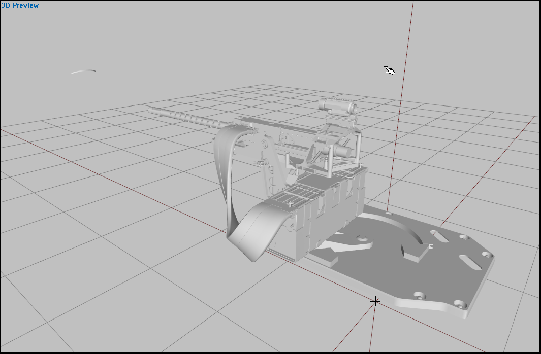
 bright echo
weight set up that will probably question your sanity
stuck oyster
perhaps make the curve a bit simpler and weight one end to the weapon and and end to the the base of the turret
best deform I found with the turret belts in SOGPF was with uniformly spaced segments and somewhat simplified curves
otherwise you may need to add few extra bones the help the belt deform/turn in different gun turn phases
 unreal jolt
trying to change the scale of a p3d file in blender but when i export it as a p3d it resets the scale back to it original size
any idea as to why it is doig this
final kayak
Potentially there are animation keys on the object's transform?
small olive
unreal jolt
any idea as to why it is doig this
apply transforms before exporting it (select your object then press Lctrl+a -> all transforms)
 tulip gyro
If I'm making a weapon, and want it to have removable iron sights, do I make them separate, or a part of the model?
stuck oyster
if you want it to be separate optics attachment then it is a separate object
tulip gyro
I want them to come stock with the gun, but be removed when you select any optic
or better yet, fold wenever you select an optic
stuck oyster
that cant be done
tulip gyro
ah well, what about the top thing
stuck oyster
only control for something like that is when optics attachment is put on
you can animate parts of the weapon then
but not when you swap between views
tulip gyro
stuck oyster
you can animate parts of the weapon then
ok so I'm assuming I make it a part of the model and it'll be it's own vertex group?
stuck oyster
yes
well it can also be multiple vertex groups if you have multiple parts to animate in different ways
final kayak
Does this look familiar to folks? https://postimg.cc/sQ7cQKb4
This is a unoptimized mesh which I'm just using for testing. It's around 85k triangles including the body geometry. I'm assuming that there's a limit of 65k triangles per mesh... or something? The geometry for the kilt only has one material. I'm guessing something's going wrong and it's applying the material for the body to the rest of the triangles.

Oddly it looks fine when using the Model Viewer through the Object Builder
 halcyon bluff
Do i have to setup more then just the landcontact LODs to make an Object use the vertical mode when used in the eden editor? I have 3 vertices as Landcontact, but it still doesnt stay normal when dragging around in the editor.
stuck oyster
final kayak
Does this look familiar to folks? https://postimg.cc/sQ7cQKb4
This is a unoptimi...
You have HL selection affecting more than the skin parts so it overwrites the textures on runtime
Nothing to do with them model complexity (though it is indeed many times more than it should be)
bleak heart
Hi, I'm making a shield mod. so i play the right arm in blender program but it doesn't play in the game.
bleak heart
https://imgyukle.com/f/2022/06/19/VHv4rN.png | Normally it should look like this.
https://imgyukle.com/f/2022/06/19/VHv98q.png | This is how it looks in the game.
stuck oyster
Your weapon bone is not in right place most likely. Hand animations calculate from weapon bone
final kayak
stuck oyster
You have HL selection affecting more than the skin parts so it overwrites the te...
Thanks for the reply. What is HL selection?
stuck oyster
its sets the skin color
final kayak
I guess when I did the skin weight transfer, it also transfered that information from the legs...
Thanks. That's helped clear things up a lot 🙂
stuck oyster
I mean you could make it out of skin instead of fabric
it would make it pretty scary
 rancid belfry
Hey so im trying to become a model maker for A3 any idea on were to start?
stuck oyster
choose a program you want to use and start practicing how modeling and texturing works
Arma specifics can be learned later after you know how general modeling works
 obtuse wagon
stuck oyster
Buldozer real Arma 3 lighting setup sample (stratis config included)
https://pmc...
obtuse wagon
stuck oyster
Buldozer real Arma 3 lighting setup sample (stratis config included)
https://pmc...
Tried this, everything worked except my mouse just didnt work anymore.. Any ideas?
stuck oyster
Nope
bleak heart
stuck oyster
Your weapon bone is not in right place most likely. Hand animations calculate fr...
how so
small olive
"vertex bounds is not a float" anyone had this issue before?
while packing an addon with mikero's tools
 tender radish
Hi everyone 🙂
I don't know if i'm in the right channel to post it but i'm trying to sign my pbos (built with PboProject)
There are some of my pbo that pass the check signatures but some not
In the RPT File, my pbo that don't pass the check signature end with Error 0x22. Test FAILED!
I tried to sign my pbo with PboProject and DSUtils but the result is the same
I have correctly put my bikey in the keys folder
 desert notch
tender radish
Hi everyone 🙂
I don't know if i'm in the right channel to post it but i'm try...
desert notch
tender radish
Hi everyone 🙂
I don't know if i'm in the right channel to post it but i'm try...
have you signed them before with a different private key?
tender radish
desert notch
have you signed them before with a different private key?
Yes
desert notch
then visit the folder containing the pbos and delete the old signatures
tender radish
already did that
i tried to clear the signatures, recreate a private key, sign the pbo with the new one, i checked the signatures with DSCheckSignatures, everything was ok but when i launch the game with Check signature ON (parameter in the launcher) or test it with a dedicated server, it doesn't work
river kite
So im running into a problem atm with my ammobelt, i set up the weigthing in blender and exported it but i cant seem to get it working, i tried different inheritions in the model.cfg but no success. im running out of ideas atm what im doing wrong
stuck oyster
the isDiscrete model.cfg parameter controls if soft or hard weighting is used by an entity @river kite
river kite
okay, i guess 0 is for weighting stuff ?
stuck oyster
I never remember which way it wemt but by default vehicles dont use it and character does
river kite
yeah i just checked in the model.cfg of the character its 0
still doesnt work tho, so seems like i still do something wrong
stuck oyster
does it move at all?
river kite
well the belt moves with the gun yeah but there is nothing happening like it should or how it looks in blender
stuck oyster
comparison pictures?
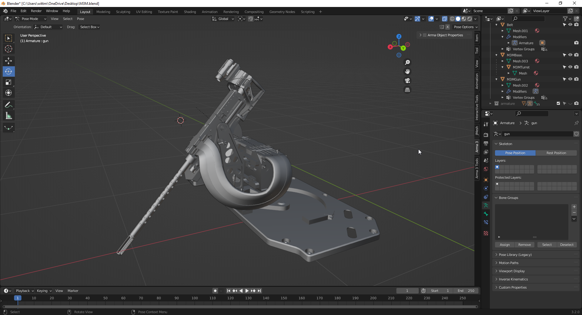
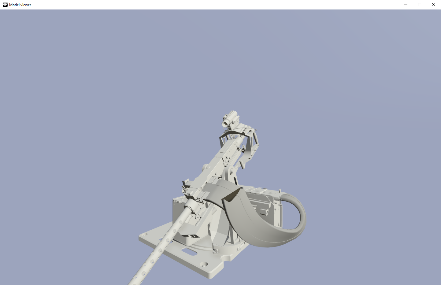
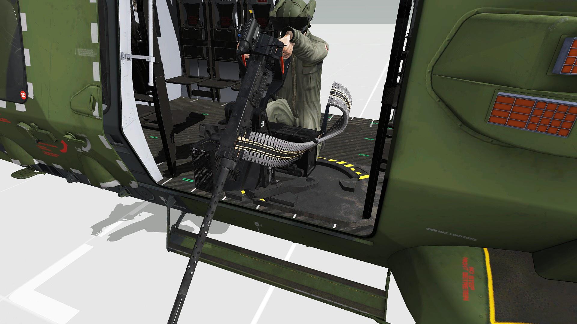 stuck oyster
is the bottome end of the belt weighted to the turret or the hull of the helo?
 rough idol
in any case, it's worth to keep in mind that weighted things with non 100% weight have to be skinned to 2 bones
if you have i.e. 68% weight to "belt1" but there is no 2nd bones weighted to those vertexes, then it will be converted to 100% weight upon binarization (buldozer viewport does p3d binarization on the fly - same as game with correctly set filePatching)
river kite
stuck oyster
is the bottome end of the belt weighted to the turret or the hull of the helo?
The bottom end is weighted to the turret which also moves the magazinebox
 pale ridge
I've got a mod composed of a single rectangular poster that I'd like to use as a prop, but it doesn't seem to be showing in Eden
it's been packed properly and stuff, and the addons folder itself just has a pbo file
is there something else that i'm missing?
stuck oyster
how do you know its packed properly if it does not work?
pale ridge
or more specifically, what's the code needed for an object to appear in eden as a prop
pale ridge
stuck oyster
how do you know its packed properly if it does not work?
it shows up in the launcher as a mod
stuck oyster
it does not mean its packed properly
stuck oyster
what do you pack it with
pale ridge
does the config file have to be packed in as well?
stuck oyster
yes most definitely
stuck oyster
png files should not get packed in at all
but I dont know why you would have different number of png and paaf iles
pngs should get converted to paa on binarizing
so please respond: What do you use to pack the pbo?
because there are many ways to do that wrong
stuck oyster
alirght so addon builder packs a pbo but it does very little checking if you are feeding it right data
do you have P drive set up?
pale ridge
yes
stuck oyster
you can check Arma 3 samples for example on what data should be where
pale ridge
ok ty
stuck oyster
or you can try Mikeros toolset and PboProject. It does have very extensive debugging.
river kite
So im still trying to get my ammobelt to work with weighting, but still hadnt any success yet. Each Selection has multiple weights to bones. i have the feeling that i do something wrong in the model.cfg but cant figure out what.
stuck oyster
belt parts should have weighting only to the gun and and turret
for animated selections
you sure you put the isdiscrete value in right skeleton?
river kite
ye
river kite
stuck oyster
belt parts should have weighting only to the gun and and turret
even when i had multiple bones in the blender scene for the setup ?
river kite
which i have, atleast i think i have it right setup, but apparently it isnt
 dusty basalt
Hey, so I have a question about animating a model
Ive got this arm that has two segments and a gun at the end. Each segment rotates around an axis that's at the end of the previous segment, so kind of like a two-segment robotic arm. How do I link these together? Right now, trying to animate them, but the rotation axis doesn't follow the previous bone, so it basically rotates around its initial position
so I've got:
SWING_1 section, that's the first arm
AXIS_1 memory LOD axis that the SWING_1 rotates around
SWING_2 section, that's the second arm ofc
AXIS_2 memory LOD axis that the SWING_2 rotates around, and it's located at the end of SWING_1
M240SWING_AXIS that the M240FULL selection is supposed to rotate around, located at the end of SWING_2
stuck oyster
you would want the bones parented in pairs
"arm1","" <- first part parented to root/nothing
"arm2","arm1",
"arm3","arm2"
dusty basalt
Yeah but it doesnt follow :/
Yeah so I tried that:
"SWING_1", "",
"SWING_2", "SWING_2",
"M240_FULL", "SWING_2"
this is in model.cfg yes?
stuck oyster
yep this is then correct
dusty basalt
I didnt know if the memory LOD axis vertices have to be assigned to the SWING_2 selections but I did that too initially
so AXIS_2 was assigned SWING_1, and M240SWING_AXIS was assigned to SWING_2
but it didnt work, the selections would rotate in their original positions
so I unassigned the Memory LOD selections from the SWING_x selections, didnt help either
at last I tried parenting AXIS_2 to SWING_1 via skeletonBones but I dont think arma liked that either
because effect was the same regardless: it just rotates around its original axis and never changes
stuck oyster
put your model.cfg into pastebin.com and link it here
dusty basalt
Im gonna do the guy Im helping a favor and paste the pieces that are relevant becasue the inheritance from the sample files got messy 😅
 dusty basalt
stuck oyster
It might be that the messyness breaks something
dusty basalt
dusty basalt
stuck oyster
It might be that the messyness breaks something
Hmmm yeah it does need some cleanup... Though don't I need to do anything else to make the bones follow each other? Maybe Im missing something but that part seems ordinary
just realized the indentation differences 🥴
Yeah so speaking of messyness, I just realized a little something
someone before me put these bones:
"SWING_1", "",
"SWING_2", "",
"M240_FULL", "",
in the global Car skeleton that was way up in hierarchy, instead of the skeleton of the vehicle vehicle we're editing, presumably by accident
so the final skeleton had both entries in... which sounds like a recipe for an error like that. Im rebuilding to test if it works
stuck oyster

final kayak
Would anyone happen to know why when testing a custom uniform in the Arsenal it wouldn't appear on the AI characters but does work on me?
 late hawk
anybody could give me a hint on how to attach a scope to MG42 machine gun? can we achieve that using script or we need to make a new mod?
stuck oyster
Would need a new mod with new model for the gun where you can add a attachment point
@late hawk
white jay
Hello
I have a question, I lost my model.cfg for the head and tried to get it using MT.
In the extraction process, the inheritance of classes in model.cfg was lost. Will it work?
class CfgSkeletons
{
    class Skeleton
    {
        isDiscrete=0;
        skeletonInherit="";
        skeletonBones[]={DiscordLimit};
    };
};
class CfgModels
{
    class test2Head
    {
        htMin=60;
        htMax=1800;
        afMax=30;
        mfMax=0;
        mFact=1;
        tBody=37;
        skeletonName="Skeleton";
        sectionsInherit="";
        sections[]={"personality", "injury_head", "osobnost"};
        class Animations
        {
        };
    };
};
 austere plank
Hey, I've had a look at all this now, but I just don't know anything about modding, I would like to add my first vehicle (own), but I have no previous experience with Blender, because I'm not familiar with it in Arma 3 Regarding modding, now I'm starting at 0 and without in-depth knowledge it's all a bit complicated, is there someone who has already brought a vehicle ingame and could somehow write down step-by-step what needs to be done or the basics from the beginning could explain purely?
small olive
austere plank
Hey, I've had a look at all this now, but I just don't know anything about moddi...
just start with something basic like a static object
stuck oyster
white jay
I have a question, I lost my model.cfg for the head and tried to get it using MT...
you can find the character model.cfg in the Arma 3 samples on steam
white jay
How to get the same effect in a thermal imager as a balaclava?
class CfgModels
{
    class Default
    {
        sectionsInherit="";
        sections[] = {};
        skeletonName = "";
    };

    class commando_helmet_v1: Default
    {
        htMin=60;
        htMax=1800;
        afMax=30;
        mfMax=0;
        mFact=1;
        tBody=37;
        skeletonName="OFP2_ManSkeleton";
        sections[]={"camo1", "camo2"};
    };
};
It will need TI stage and texture in its rvmat
white jay
stuck oyster
It will need TI stage and texture in its rvmat
class StageTI
{
    texture="republic_commando\data\textures\empty_ti.paa";
};
to
class StageTI
{
    texture="#(argb,8,8,3)color(0,0,0,0)";
};
?
stuck oyster
0,0,0,0 would mean it shows no heat
white jay
stuck oyster
0,0,0,0 would mean it shows no heat
Thanks
 muted tapir
is it possible to generate a model (just some variation of a quadrangle) that arma accepts and can use textures (via hiddenselections) and collision on without manually running it through object builder?
probably by writing a program that assembles the file how want it?
muted tapir
i'm thinking of trying to make a mod that adds craters from explosions using the new terrain deformation from the dev branch. to make it look better than just a very large, edgy hole in the ground, my idea is to cover up the hole in the terrain using 7 objects:
one crater-shaped object as well as 6 triangles with a corner cut off to mask the hole in the terrain. my idea would be to add a lot of possible triangles (with a corner cut off) with the corners distributed at basically 10 centimeter intervals over like a meter or something, which i assume would require around 500 different models to cover all possible shapes.
stuck oyster
or just 1 triangle you animate to fit?
muted tapir
is... is that a possibility
stuck oyster
buut preferably your crater would just cover the hole
well that ist no even possible always
since the terrain deformation uses terrain cells
which are differerent on most terrains
some might have 5 meter cell
some 2 meter
 muted tapir
stuck oyster
muted tapir
stuck oyster
it's that simple for flat ground
that doesn't really work anymore once the ground stops being flat
idk maybe my idea is just crazy
stuck oyster
 muted tapir
now add a third dimension
stuck oyster
its not crazy but it will likely not work in all terrains
muted tapir
I'm aware of that
stuck oyster
or well
if the crater has enough coverage it could fill larger hole too
but could be tricky
and of course hitting between terrain verticles could not be easily fixed
muted tapir
stuck oyster
if the crater has enough coverage it could fill larger hole too
even with a cell size as small as 4 meters the terrain hole will always be at least 11 meters wide
stuck oyster
8 meters
muted tapir
you forgot the diagonals
stuck oyster
ah true
muted tapir
but you're right, maybe it's simpler to achieve my goals with like 10 different variations of crater object and no cover objects
muted tapir
stuck oyster
or just 1 triangle you animate to fit?
how would i animate a triangle?
stuck oyster
bone for each verticle
stuck oyster
animations can be defined with wide range that you can animate from and to
muted tapir
can i run multiple animations using different bones on the same triangle at once?
stuck oyster
yes
muted tapir
that sounds great
stuck oyster
if you want 3 axis translation on each verticle, each bone would have separate X Y Z animation
geometry might be problematic though 🤔 not sure how that would behave
muted tapir
geometry meaning collision and stuff?
i think i could make it work with just z animation and different models for different terrain cell sizes
muted tapir
I just realized i can probably animate a hole-filling crater object to match the borders of the hole
desert notch
muted tapir
i'm thinking of trying to make a mod that adds craters from explosions using the...
You don't need "500 models". Just make a few for randomness
Then scale them using setObjectScale to match any crater size
desert notch
muted tapir
now add a third dimension
There is no problem with "3rd dimension"
muted tapir
desert notch
You don't need "500 models". Just make a few for randomness
That I've realized by now as well. I've abandoned the idea with the triangles which would have required a ridiculous amount of models.
muted tapir
desert notch
There is no problem with "3rd dimension"
There is, the crater is a lot smaller than the hole in the terrain, and if say my crater object was made for flat ground, it would look weird in valleys and on hilltops.
For valleys that problem would be easily fixed by adding a separate model for valleys, on hilltops (by hilltops i mean outwards bends in the terrain, i dont know how to properly call it in English) the crater object that fills the entire hole needs to match up with the borders of the terrain hole without there being steps.
Making one crater object that does that for all hilltops is as far as i can tell right now not possible, unless i manage to animate the borders of it so i can adapt it to any position.
desert notch
muted tapir
There is, the crater is a lot smaller than the hole in the terrain, and if say m...
you just said you intend to use setTerrainHeight. so you can make the terrain match the shape of the model, not the other way around
muted tapir
That would result in alterations in the terrain in a very large area around the crater
With a cell size of 4 meters which you can find on stratis for example ot would result in an area that is up to 22 meters wode being altered, with a cell size of 10 meters or whatever maps like malden use, the altered terrain would be up to 56 meters wide
desert notch
no, why would it be?
you just modify the tiles you need based on crater size
even if cell size was 50 meters you just modify 1 pixel for a 20 m radius crater for example
muted tapir
I know that the alterations would be quite small, however i fear that it would lead to either (if i move the objects in that area) an observable jump in objects like houses or (if i dont) small ground objects ending up underground or floating everywhere
muted tapir
desert notch
even if cell size was 50 meters you just modify 1 pixel for a 20 m radius crater...
If i change one point in the terrain grid, it affects all neighboring cells.
Since I'm already moving one point to make the crater exist in the first place, i'm already modifying 4 terrain cells. If i now adjust the borders of those cells, it will affect a radius of 2 terrain cells around the center of the crater
desert notch
let me write a quick script to show what I mean
muted tapir
Do so, i would be very happy to see a way to modify the terrain less
dusty basalt
I have returned with questions
Is there a way to combine two controllers/sources for one animation?
Context: I'm modding an airplane which has its airbrakes, but they are supposed to extend by a couple more degrees when the plane is on the ground. Is there a way to put these together into some sort of expression?
Also it seems there is no particular controller to check if the vehicle is touching ground, but I guess the gear damper can be a source of this information
stuck oyster
dusty basalt
Is there a way to combine two controllers/sources for one animation?
Context: I...
For one animation, no but you can add multiple animations that all affect the sane bone.
dusty basalt
stuck oyster
For one animation, no but you can add multiple animations that all affect the sa...
so if I add two animations to the same bone, one which rotates it around axis X by 30 degrees and the other around axis X by 20 degrees, I should end up with 50 degrees of rotation with these two combined? Or is there some additional concerns?
stuck oyster
Yes that is correct
dusty basalt
okay, lovely, I'll give it a shot
tbf it mostly is about changing the range of the same animation once it touches ground but Im not sure how I could achieve this
desert notch
@muted tapir I messed with this a bit more than I wanted to but anyway here it is:
https://sqfbin.com/kirocuqewigixevoqowa
it's not perfect and I'm not sure if it is what you wanted
but anyway it looks ok on "hilltops" and slopes


also the script is a bit of a mess and needs some optimization
to test the script, just look at a position on the terrain then open the console and execute
muted tapir
@desert notch it's not what i had in mind originally, but it works well and solves the whole crater thing i had in mind producing a crater that probably looks better than what i would've produced.
if it's allright with you, i'm gonna tweak that script a bit, add destruction of vegetation and scorch marks and stuff, find a way to tie it to large explosions and release it as a mod after 2.10 gets released
i'm also gonna take my original idea and see if i can make clean trenches with it
desert notch
sure go ahead
muted tapir
thanks
desert notch
muted tapir
thanks
I added some comments in case you can't figure out some parts:
https://sqfbin.com/ofuwehonezoyilinuwat
muted tapir
thanks
desert notch
the last few lines where I create a hashmap and stuff is to fix this problem:
#dev_rc_branch message
 silver zenith
is there a way to handle alpha sorting through blender?
its always kinda messed up when I open it in bulldozer.
stuck oyster
there is a transparency level tool in there I recall
Im not 100% sure how it was used though
 hard oasis
Hey i was modelling a uniform and one of the shits Arms has it's textures on it's inside now like i can see the back texture from the front and vice-versa
any idea in a fix?
stuck oyster
your faces are wrong way
arma has 1 sided faces only and yours are pointing back instead of front
hard oasis
do you know a way for Blender to show the front of the faces?
and flip the of course
Fixed:
Show Overlays - press Face Orientation under geometry, (red is inside/blue is outside)
take the textures that are inside out and press Alt+N and flip it
// keeping it her for the record
 fluid copper
Is there any documentation or knowledge on how exactly arma 3 creates a bounding box for an object?
stuck oyster
@fluid copper out of all combined bounds of an object
in most situations at least
whats the context
fluid copper
I had an idea for a mod and thought using bounding boxes to measure distances for things would be an effective way of doing it, assuming of course the box was accurate. I would be making the object that does the measuring so I could modify its model in order to produce an accurate bounding box.
They have always seemed incredibly inaccurate to me, especially for objects like buildings and vehicles. I think as long as I keep my object relatively rectangular in shape that it should be alright.
I kinda wish it was possible to manually create the bounding box for an object
stuck oyster
things like proxies often mess up the full bounds as they are often way big and point out of the model
the bounds cant be set manually
but you can add memorypoints into your model and read them via scripting
they can create bounds or act as snap points depending on what you want to do
fluid copper
Thats a really good idea with the memorypoints, I think I will take that approach. Thanks!
unreal jolt
Doing some work in blender was wondering if there's a way to mirror what is being done like say I have a bust from arma 3 and I wanna mess with the ears is there a way to select one side and have it mirror the changes that I'm doing on the other that way it doesn't come out different
stuck oyster
There are mirror tools in blender yes. The model however might not be mirrored so the tools don't always work.
 twilit spear
is there any way to get a enhanced combat helmet in blender?
twilit spear
ok
 lunar trench
Hi everyone
I could really use some advice on Geometry as i feel like i have had enough with banging my head against the wall 😆 My experience has been very hit and miss and im not entirely sure what im doing wrong.
I have had smaller models where i added geometry that was just a simply cube to block it out and that worked fine. But as soon as the model gets a bit more complex and i need to block that out things start to get wonky and not work (allowing me to walk through the model)
What is the proper way to create geometry and to set weight on it? (I use blender with the addon) I assume the weight part is what i mess up as i currently use some arbitrary numbers im guessing myself to.
Any tips and tricks, do's and don'ts would be greatly appreciated. Even if you just have a link to a tutorial where its explained. (I feel like i have watched pretty much all youtube videos on it and i still fail, especially walkable surfaces)
Thanks for any advice in advance!
small olive
lunar trench
Hi everyone
I could really use some advice on Geometry as i feel like i have ha...
lunar trench
small olive
https://community.bistudio.com/wiki/LOD#Geometry
Thank you and yes i am aware of the wiki entry. I just feel like it isn't very specific. Like what is the "mass" of something? Is this a "made up" value or is this in kg or something totally different? How do i know what mass i should set on the object?
Then you have the whole part of there being a max width to it but no one knowing what it is. What if i have something thats larger than the 50-60 m in width? Can i somehow create multiple geometry objects in the same model to fill that entire surface or is that simply not possible? Example, i have a ship thats 100m long.
small olive
afaik yes, ships are made by setting multiple models as one section in-game
mass is in kg
100.00 = 100kg
and also verify the other rules
check that your model is convex and closed
lunar trench
I see, so they "cheat" a little like with the carrier that is "put together" by multiple parts?
lunar trench
small olive
check that your model is convex and closed
gotcha, i will give that a go. (not something i have done before) Appreciate the input
small olive
lunar trench
I see, so they "cheat" a little like with the carrier that is "put together" by ...
not sure but yes I suppose
small olive
lunar trench
gotcha, i will give that a go. (not something i have done before) Appreciate the...
you can do it in Blender but also in Object Builder
lunar trench
I know it says simple geometry. Do you know if they only want squares for this or if its okay to use something that is a little more complex?
small olive
don't forget making them convex
for example:
this part of the aircraft is not convex
but it's two seperated part, so it's valid
but since it's for calculating collisions
you should make it as simple as possible
for saving performance
lunar trench
is what you use here in the screenshot your geometry?
small olive
it's fire geometry
small olive
that's the geometry
not even need to make the curve because there is nothing can collide with there in-game
lunar trench
I have tried to keep it super simple so far like in the wiki, so something like this basically:
 small olive
so there is something with being closed and convex
to check that in Blender
select the edit mode and do it like this
that will find the unclosed parts of your mesh
then fill them
to check convexity
well it's not checking but genuinely fixing it
lunar trench
I will try this as soon as i get home. This has been very helpful, thank you very much!
small olive
no problem
lunar trench
Last question before i forget. Do you happen to know what the "roadway size limit" is? I know they can be 72 m in length, but does that go on both axis? Like could i make a 72 m by 72 m plain as a roadway?
small olive
I haven't done that before but the answer is yes according to wiki
lunar trench
👍
stuck oyster
@lunar trench sticking to max 50 x 50 meter piece max would be my advice
Geometry component needs to be convex, closed blob, have componentXXX name and have mass.
And preferably be max 50x50 meters
lunar trench
stuck oyster
<@233610558098767873> sticking to max 50 x 50 meter piece max would be my advice
roger that
stuck oyster
The size limit has roots in how the terrain simulation/calculation works. Terrain is split into smaller grid and things like collision detection is calculated in the grid cell the object is in and in all the adjacent cells. But if object goes beyond the adjacent cell the collision stops working. 50meters is commonly safe size but it can vary between terrains.
 valid charm
@stuck oyster Does the mesh have to be triangulated?
stuck oyster
Quads can work but for accurate edges triangulation is better.
Also it needs to be all sharp edges
rapid tree
hello can someone explain to me how i can give my weapons accurate vanilla reload animations without a mag insert delay ? like time it correctly and what are the things i have to look out for it ?
inland pawn
rapid tree
hello can someone explain to me how i can give my weapons accurate vanilla reloa...
Speed up the mag insert speed in the model.cfg?
Though I’m not sure how possible that is
inland pawn
Do you not have a magazine move entry?
rapid tree
inland pawn
Do you not have a magazine move entry?
no
inland pawn
What kind of weapon are you doing
inland pawn
Ok, then you should have a set of memory points for your magazine to move, then add a model.cfg entry using the magazine and the new set of memory points you just made
rapid tree
i have magazine axis from the sample weapon
inland pawn
Then use that
rapid tree
so the mag movement speed is dependable on the weapon ?
inland pawn
I think how fast it’s moved is through the model.cfg
Though I haven’t done that before so idk if it’s possible
rapid tree
of the weapon or mag ?
inland pawn
Mag
rapid tree
i see
inland pawn
Do you know how to even add movement to the mag in your model.cfg?
rapid tree
no...
i would need a full model cfg to study it and play around with it
so doing some research resulted that it is dependable on the weapon
rapid tree
any bohemia, cup or rhs dev here ?
stuck oyster
Sample weapon in the Arma samples should have moving parts@rapid tree
And wiki pages for model.cfg and "how to animate a model" explain how model.cfg works
rapid tree
stuck oyster
Sample weapon in the Arma samples should have moving parts<@856672181559230504>
So the mag reload anim is modified with the weapon model.cfg and not the mag model.cfg ?
stuck oyster
It is in both if I remember right of you want to animate parts of the magazine to. Move. Like bullets
But the weapons animations are in the weapon model
 viscid berry
Your ShadowVolume has to be closed
muted tapir
viscid berry
Your ShadowVolume has to be closed
i added a closed shadowvolume, it's still the same
viscid berry
Does your Model fulfil these requirements? https://community.bistudio.com/wiki/LOD#ShadowVolume
muted tapir
i didn't triangulate it, maybe that's it
i triangulated everything, now it works, thanks
rapid tree
Is an A3 dev here ? I need to know if there is an limit for how many rotors a helicopter have, the model i try to armafy have 4 rotors
marsh canyon
Best bet is rayhard here, and I ain't, but I don't believe there is a limit
inland pawn
rapid tree
Is an A3 dev here ? I need to know if there is an limit for how many rotors a he...
Pretty sure theres not. It just comes down to how many base A3 supports through what’s in game. After that, it’s do it yourself through model.cfg
rapid tree
inland pawn
Pretty sure theres not. It just comes down to how many base A3 supports through ...
The thing is i adjusted the model.cfg to fit 4 rotors but the other 2 are not animated
stuck oyster
The vehicle simulation only has 2 but there is no limit on animated parts
Except bone limit of 255 bones
rapid tree
Does that mean that im only able to do rotor blur for 2 Rotors ?
stuck oyster
You have 2 sources but you can swap as many parts as you like
The swapping is just selections that get hidden/unhidden
rapid tree
The sources are defined in the config so basically i have to make a new base heli ?
rapid tree
Oh wait sorry brainfart 😂
But i dont get why the Animations dont work for the other 2 rotors, they can be selected in the anim view
stuck oyster
Typo somewhere, wrong bone inheritance, too many bone selections on mesh, some other mistake
rapid tree
stuck oyster
Typo somewhere, wrong bone inheritance, too many bone selections on mesh, some o...
idk what i did but it works now 🙂
 jade flare
anyone got any guides on how to make custom scopes?
jade flare
I have the sample and moved it to P drive, then used PboProject to compile it but its not showing up?
stuck oyster
weapon would need to be configured to use it
compatibility with a weapon is not automatic
dusty basalt
How can I fix the offset of the player from the ladder? Ive managed to make the player face the ladder but the character is basically inside of the ladder, with the back stuck inside of the rungs pretty much
stuck oyster
move the ladder points
also direction of ladder is dictated by slight angle/offset between the points
dusty basalt
stuck oyster
move the ladder points
I did try that, moved the points and the roadway but it doesn't seem to do much difference
jade flare
stuck oyster
weapon would need to be configured to use it
Ah, where can I find a example of this? I do have a all in one configuration so more of a pointer on what to look at.
stuck oyster
any weapons attachment slot if I remember right.
jade flare
so basically grab
    class arifle_MX_khk_ACO_Pointer_Snds_F: arifle_MX_khk_F
    {
        author="$STR_A3_Bohemia_Interactive";
        _generalMacro="arifle_MX_khk_ACO_Pointer_Snds_F";
        class LinkedItems
        {
            class LinkedItemsOptic
            {
                slot="CowsSlot";
                item="optic_ACO";
            };
            class LinkedItemsAcc
            {
                slot="PointerSlot";
                item="acc_pointer_IR";
            };
            class LinkedItemsMuzzle
            {
                slot="MuzzleSlot";
                item="muzzle_snds_H_khk_F";
            };
        };
    };
and just make a new class using this and replace the cowslot with my optic?
stuck oyster
linked items are what get to be placed on the weapon class as default
jade flare
stuck oyster
any weapons attachment slot if I remember right.
so im not sure what this means then?
stuck oyster
its this stuff
 stuck oyster
if you want your new optic to be compatible with other weapons you add it to this list
jade flare
class CowsSlot_Rail: CowsSlot
{
    class compatibleItems
    {
          Test_scope3D_01 =1;
        };
};
I guess I don't need to add the whole list of scopes?
stuck oyster
🤔 Im thinking no, try it out
jade flare
also cheers every time I tried my hand at different bits of A3 you've helped me out
still no luck heres what i got with my P drive layout in comment block
https://paste.ofcode.org/YsnE6ejMaANvpiDAQ6H4tV
 limpid matrix
hey, so im making a uniform and im trying to figure out how to make it so it has Ballistic Protection/Explosive Resistance/Load/Weight, basically I want it to be the same as the default military uniform, how do I do it?
inland pawn
limpid matrix
hey, so im making a uniform and im trying to figure out how to make it so it has...
That’s all Config
limpid matrix
inland pawn
That’s all Config
yes but what in the config
inland pawn
limpid matrix
yes but what in the config
Armor, hitpoints, load, mass
limpid matrix
inland pawn
Armor, hitpoints, load, mass
thnx
desert notch
is there any limit on the number of selections, bones, animations, and rvmats a model (or certain LOD) can have?
 charred bolt
desert notch
is there any limit on the number of selections, bones, animations, and rvmats a ...
charred bolt
desert notch
is there any limit on the number of selections, bones, animations, and rvmats a ...
255 bones per model
rvmats probably not limited, except that you should keep section count (texture+rvmat) to a minimum for good performance
stuck oyster
2048 named selections
silver zenith
made a model similar to the small sandbag bunker, polycount is like 90k, which of course is unacceptable
but would it be an ok res1 if the res 2 is 20k and res 3 is 9k?
theoretically there is a way I could get rid of a lot of polygons but I'm not sure how
since a lot of the sandbags have clipping faces between each other, just not sure how to do that in a smart way
tried with a collection boolean but it somehow added more faces rather than removing them
hot hornet
90k seems a lot for a structure
silver zenith
its mainly the sandbags
there are a lot of faces I could remove but I have no idea how
hot hornet
Can't you try to lower the polycount of the sandbags a little ?
silver zenith
yeah if 90k is too much for a res 1 I'll just use what I had planned as res 2
which is 20k
or if it gets extreme the 9k res 3
silver zenith
thats what the res2 and 3 are
but even those have the shitload of internal faces
I'll just do it manually I guess
stuck oyster
manual might be the way to go there
you will want to keep the uvmapping intact as long as you can
hot hornet
Manual retopology is always better. Boring but better.
stuck oyster
and any automation can easily break it
silver zenith
yeah the sandbags are unwrapped and textured so I dig my own grave
hot hornet
Oof
stuck oyster
multimaterial?
silver zenith
nah I'm just using the same sandbag texture I'm using for all props using sandbags
hot hornet
Ohhh yeah, do multimat for structures. Much much better for performances
silver zenith
I though I had learned multimats but they just ended up confusing me
for example I was stuck with one specular value for all textures in the multimat, also sometimes the "mask" method ended up giving me blurred borders
so I gave up the performance improvement for my sanity
I do miss being able to give ambient occlusion to tiled textures
stuck oyster
Multimaterial does not do shiny metal things very well. that kind of parts should be done with supershader
silver zenith
yeah
I guess the way to do it is to group all textures with similar spec value in their own multimats
which ends up creating more drawcalls negating the performance improvement
stuck oyster
multimaterail does use SMDI for each texture that can modulate the specularity of a texture. I admit though it can be difficult to use and the adjustment range is still limited
silver zenith
I'm in no way coping for not using multimats
I'm just fully aware I'm too stupid to do them right so I'll sacrifice a little bit of performance for my mental sanity
 silver zenith
is there a way to do supershader tiled textures and still somehow having an ambient occlusion on the model like in multimats?
silver zenith
oh interesting
and what would the tex1 have as rvmat?
an empty multimat with just the AO?
stuck oyster
No the those change what uvset a stage in rvmat uses
 runic plover
silver zenith
there are a lot of faces I could remove but I have no idea how
runic plover
silver zenith
there are a lot of faces I could remove but I have no idea how
Blender
Be in object mode
Click sandbag layer
To the right click the service tool
Select Decimate modifier, if you decimated it, select the little arrow which shows down, and press apply
Repeat this for resolution lods or if you want to pull down the pily count. Works pretty well
Example i did with one of the snow rocks
First lod vs last lod (there are 6 reso lods i did)

 silver zenith
yeah did that
still I'll want to do the manual process anyway because decimate won't remove the geometry that I won't need
a mix of both I guess
runic plover
If its not unwrapped or still needs to be unwrapped
In OB
Select some of the points
Left Shift + D
silver zenith
they are unwrapped but you got me curious
what does that do?
runic plover
It deletes / merges points together
But mostly, if you want to delete faces you need to do a new unwrap
Best way to keep the uvw mostly is the decimate way i think
runic plover
silver zenith
they are unwrapped but you got me curious
what does that do?
Try it out 😅
silver zenith
oh I get it
yeah I'll just do a decimate and yoink what I can manually
runic plover
I use it a lot when i do some geometry stuff and convex them and some open faces are still around, so i select these points, shift D and convex again, solved
I dont work in blender, just learned how to make reso lods in blender because in OB they get fucked up
But modeling stuff i still do in OB
Im sure in blender is a better way to work manually what you search for
hot hornet
decimate to keep UVs yeah
unsubdivide will break your UVs
use retopoflow 3 to retopo your meshes
you can also try Quad Remesher
kind nacelle
or instant meshes
civic stratus
How is the location of a stored launcher (on character back) determined?
 bold flare
I think the character has a bone called "launcher", thats where its put onto
civic stratus
Does "squarizing" topology for body mesh improve visual quality for weight painting/animations?
 rustic escarp
Whenever i shine a light on my emmissive, it gets much brighter, im not sure why
stuck oyster
civic stratus
Does "squarizing" topology for body mesh improve visual quality for weight paint...
no, it makes it more unpredictable
 void panther
Having issues with a model of mine. It's a main gate for a map I'm making, I have 6 lights on it however I can only get the flares to work and 1 reflector (like light shining on the ground). Does anyone have any idea how to get the lights to work? I've pretty much exactly copied the config and stuff from the samples, and I've triple checked my model to ensure all the selections are correct and the memory LOD is correct. I've also gone into the cfgviewer and ensured the code is correct there too.
stuck oyster
does the scene have a lot of other lights present?
are you testing it as terrain placed object or as editor placed one?
void panther
I thought that may be the case, and tested it with only 2 lights, however I still run into the same issue. This is a terrain placed object. I have class=housesimulated in the properties as well
stuck oyster
whats its damage type?
void panther
It won't work with eden placed either, however I will confirm this now.
stuck oyster
damage named property that is
void panther
And I'm unsure, I don't think i have it set, I remember reading about that though and how the lights would not work if it was set to "NoDestruct" or something
I will set that now
stuck oyster
yeh I recently came into issue with the noDestruct or damage = no named property and lights
void panther
What should it be set to for a structure?
stuck oyster
building is commonly used
void panther
thanks!, I'll test now 🙂
stuck oyster
and damage = buidling is what worked for my lights
void panther
nope, still only 1 light works. The flares work on the other lights but its only projecting an actual light source from i believe the first light. There's also a weird bright flare in the middle of the model however I have no memory points there
actually there are no points in any LOD where the mysterious flare is coming from
If you have a moment to trouble shoot with me I can PM you. It would be much appreciated!
stuck oyster
soz I dont have time to go that deep into things. I feel like I have had similar issue but cant pinpoint what the solution was. I'll let you know if I remember something
void panther
thanks!
void panther
after doing some additional reading, I was able to get it to work by commenting out the "AggregateReflectors" section in my config.cpp
I found out this combinds the light sources together to reduce calculations
marsh canyon
What is the plane/helicopter side p3d requirements for Vehicle Loadout?
Can't seem to make it visible properly
Never mind, got it working - I've used \a3\weapons_f_jets\ammo\pylonpod_missile_aa_06_x1_f
lunar trench
Could someone explain to me how helmets work? 😂
I have created a 3D model for a ballistic face mask, put it in game etc and it all works great. Now I'm trying to get my armor values right etc. which of course is config stuff, again no problem here.
What i would like to learn is how Arma knows "where" to apply the values from the config? There isn't really any geometry in the model which is what confuses me. (I looked at a vanilla helmet for reference) So does it just automatically take whatever mesh there is in 1 or is there some predefined invisible bubble around a characters head that is predefined as "Helmet" which just protects you equally on all sides based on the values in the config? (Ideally my Face Mask should only protect from the front and not the backside)
small olive
afaik, it's just increasing the head's armor value, there is no model to calculate bullet collison for body part protection, body parts are the protection itself basically
it should be in the config like where the protection applies for when you wear it
lunar trench
small olive
afaik, it's just increasing the head's armor value, there is no model to calcula...
I see, thank you. Do you know if i can add actual "Geometry" in the model instead of the empty geometry placeholder to sort of create a impenetrable shield?
small olive
you can do that by increasing the armor value so high
lunar trench
Yea i get that, but i don't want it to be all the way around the head since the face mask only protects from the front. So i was thinking of doing the opposite by reducing the Armor value to basically 0 and then having actual geometry in the model completely block the shot (if it hits the mask) but then when hit in the back of the head you would go down because there is no geometry
inland pawn
lunar trench
Yea i get that, but i don't want it to be all the way around the head since the ...
Fire geo I believe will get what you want
lunar trench
inland pawn
Fire geo I believe will get what you want
i will give that a go, thank you
jade flare
jade flare
still no luck heres what i got with my P drive layout in comment block
https://p...
I'm still stuck on this?
Custom 3D Scope and I'm using the sample pack but cant get it to show up in engine.
Used PboProject no errors.
muted tapir
how do i define which point in my model is the coordinate center of the arma object?
nevermind i have actually succeeded in doing so
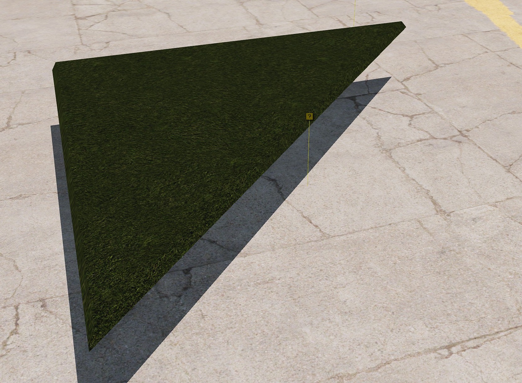
how do i change the position of the yellow icon in the editor?
stuck oyster
if I remember right it should be at the center of the model bounds
it should not really matter though
muted tapir
i suppose i can't change it then
i always thought it was an indicator of the coordinate center
stuck oyster
Also notice new embed rights for all users on this channel. This is new priviledge, dont mess it up (general notice for everyone)
muted tapir
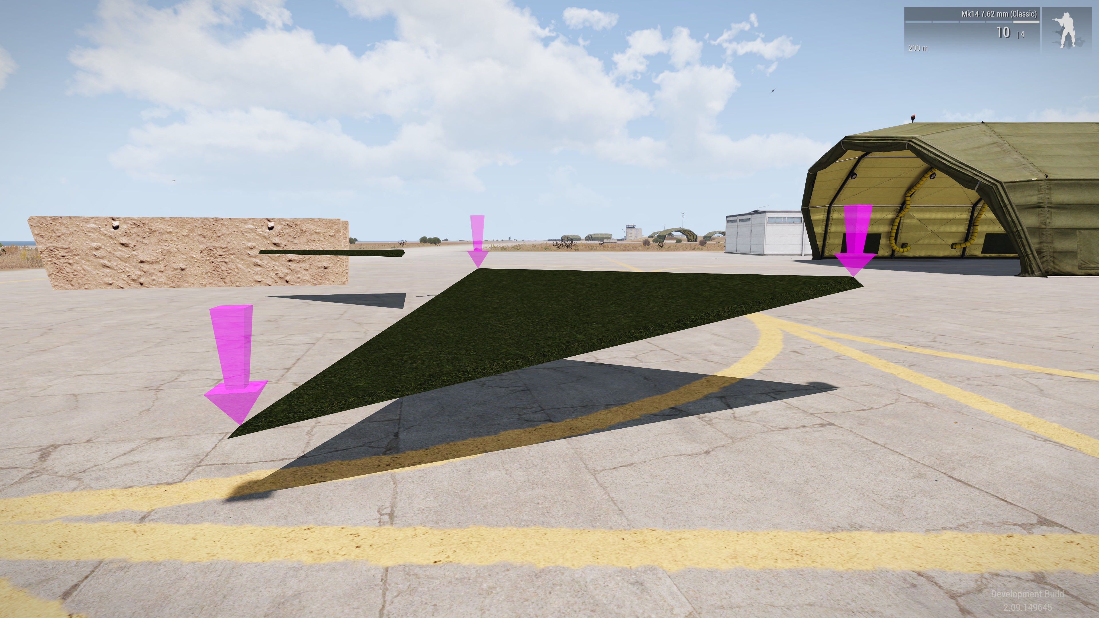
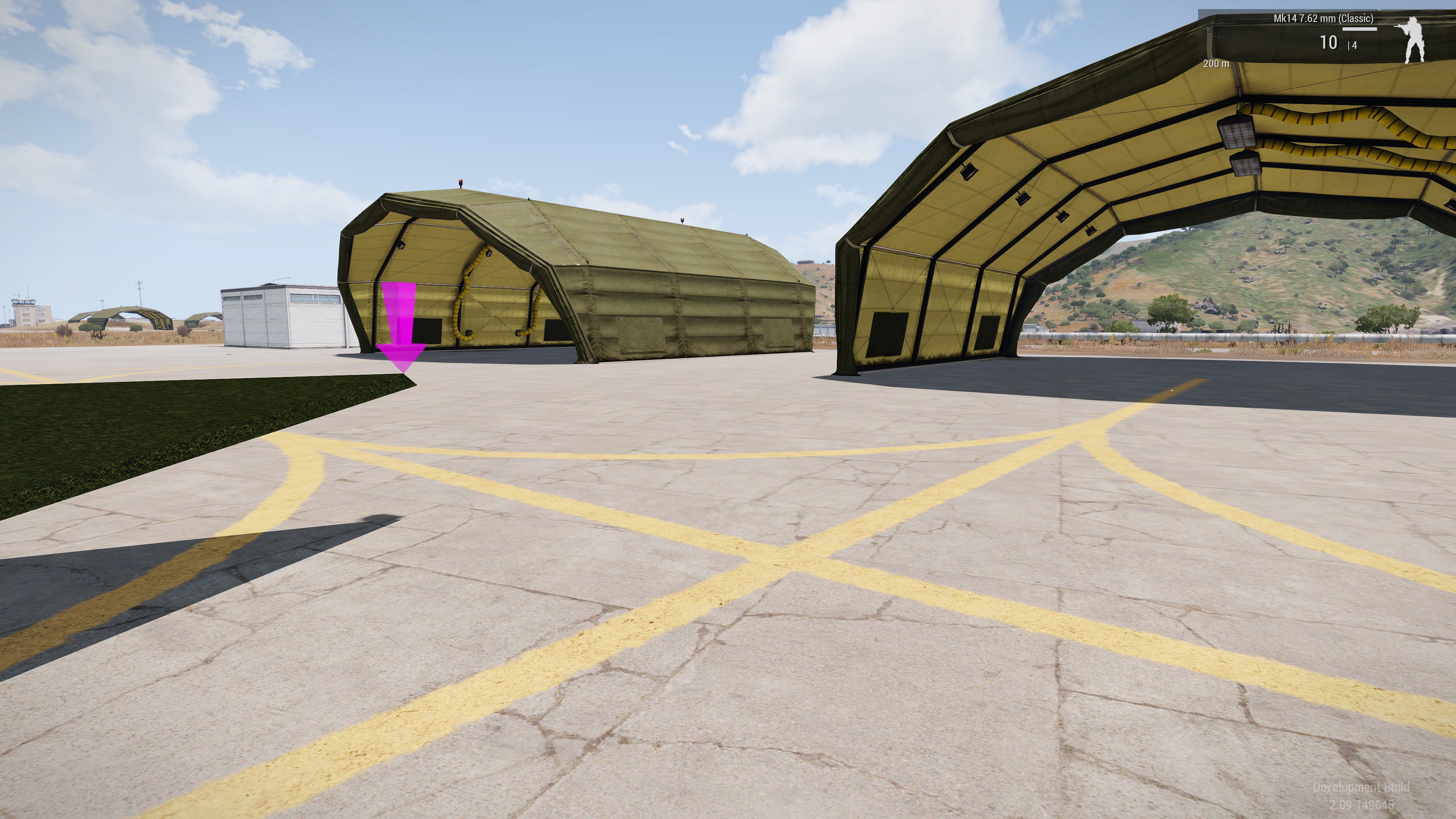
what are the conditions that cause my object to no longer be rendered?
i have animated the object to completely change shape and position
stuck oyster
does it animate away of its original position
basically bad stuff happen if mesh moves beyond its original bounds
muted tapir
so can i expand the original bounds without expanding the model?
stuck oyster
so it would need fake bound points to make it by default "maximum size"
muted tapir
how do i make the fake bounds?
stuck oyster
geometry also stops working beyond the bounds
muted tapir
that explains some weirdness i've encountered
are there any drawbacks to expanding the bounds too far?
stuck oyster
no
stuck oyster
well it will cause the object be more visible
buut dunno if thats a drawback
since you will want it to be visible at distance
muted tapir
i'd say thats the intended effect
muted tapir
the expanded bounding box works for getting it rendered, but not for the geometry LOD
are single vertices in the geometry lod a problem?
apparently they are not and everything is working now
stuck oyster
wee
 drowsy flicker
hey guys, im looking for a somewhat efficient way to make my model look damaged. so far i generated a damaged normal map in blender, but
a: it looks kind of strange
b: i have my difficulties to color the damaged regions different to simulate scraped of coating / color.
Has anybody some tips to generate some "battledamage" on normal maps and color maps?
inland pawn
drowsy flicker
hey guys, im looking for a somewhat efficient way to make my model look damaged....
ARMA has built in rust and damage rvmats you can reference for a wreck state
inland pawn
drowsy flicker
oh! That sounds useful!
Where can i find these?
Your p drive a3 folder
drowsy flicker
ah. Will take a look at that. Thanks!
civic stratus
should seperate models be made to be used as ground models for vests/backpacks?
stuck oyster
if you want them to look different on ground you can
items/gear gets placed into a groundholder object when dropped on ground
civic stratus
they seem to float above the ground level by a few feet
stuck oyster
when you drop them?
civic stratus
yes
 timber night
Can someone explain to me
whats going on with my model
in object builder
Maybe my hat is to high poly?
or normals?
stuck oyster
you have faces pointing wrong way
Arma draws only front side of face
and you have modeld yours with mixed directions
youll need to turn them to face out
@timber night
 bright flax
Is it possible to change just a .rvmat of a texture to a camo selection?
stuck oyster
you will have to explain a bit more what you mean
bright flax
https://imgur.com/a/y5FEA6z
This is my building, what I want to make is "turn off the red light" (mc texture) for this I need to change the rvmat
stuck oyster
That might not be possible
 fierce vessel
Does anyone know how I can contact the RHS developers? I'd like to edit the HGU-56 model to remove the black velcro patches at the back of the helmet, and was hoping to get their permission (and hopefully help) in doing so.
marsh canyon
Ask PuFu. But whatsoever it can't be because BI disallows to modify an existed p3d
runic plover
stuck oyster
That might not be possible
You can, there is setObjectTexture and setObjectMaterial
I did the same with the green, blue, red Tiberium, using just 1 model for all 3 variants
stuck oyster
did those work on terrain objects?
runic plover
Maybe
runic plover
I just know on regular objects it works because i got to change for all 3 variants the rvmat file to make them glow in the correct color
runic plover
Iiiiiit could work because you can also open and close doors or disable / enable lights with a user action added.. so it cooouuuld work.. could
Also a option could be via ID
 karmic blade
Question, I have a model and I would like to add many variants of it with different textures set in config file, I know I need to do smth to the model, add hiddenselections or smth for that right? How do I do that?
stuck oyster
hidden selections are vertex groups/named selections on model usually named "camo, camo1, camo2" etc but name can be anything you like
a selection needs to have only single texture mesh parts in it, cant have 2 different textures on it or crazy stuff happens.
the selection names must then be listed in the model.cfg sections array list
and then set up in the config.cpp class hiddenselection... parameters
timber night
is this UV Unwrap ok?
@stuck oyster I'm pretty sure my faces were correct for the hat
 merry pike
This must be a really simple thing, but I can't figure out what determines whether an object snaps to terrain normal or not in the editor. atm my object stays horizontal all the time.
stuck oyster
could be better but that works
stuck oyster
merry pike
This must be a really simple thing, but I can't figure out what determines wheth...
does it have land contact points?
stuck oyster
timber night
<@150949769953411072> I'm pretty sure my faces were correct for the hat
you cant see it in blender unless you turn on backface culling
timber night
Ohhh
stuck oyster
or switch view mode to see face orientation
merry pike
stuck oyster
does it have land contact points?
it does. Is there anything specific about how they should be?
stuck oyster
timber night
https://gyazo.com/84a5707c134fd5ca6be2f105f4f2ea61
something caused them to flip
stuck oyster
merry pike
it does. Is there anything specific about how they should be?
what placement type does it have?
I think that played a part
timber night
Is blue not good?
stuck oyster
its a named property in geometry lod
timber night
How would I fix that
stuck oyster
make sure your object scale is 1,1,1
timber night
in blender?




 merry pike
geom lod has placement and not matter which value I put there, it hasn't helped
stuck oyster
what type of object is it?
stuck oyster
👍
timber night
it was always 1,1,1
merry pike
a very simple prop. Practically first I've ever done, so excuse my noobness here
stuck oyster
then it could be problem with your texture too. make sure you save it with _co suffix and that it does not have alpha transparency channel
stuck oyster
merry pike
a very simple prop. Practically first I've ever done, so excuse my noobness here
does it inherit from like house or something else in its config @merry pike
merry pike
Not house but a VR helper object which does behave the same way...?
so it's something like the simulation property in the config then?
stuck oyster
yes I think so
keepHorizontalPlacement=1;
it has this
you want that as 0
then 👌
merry pike
yeah that must be it. Thank you so much mr Goat!
stuck oyster

fierce vessel
marsh canyon
Ask PuFu. But whatsoever it can't be because BI disallows to modify an existed p...
Even if contacting the mod developers to get an original copy of the model?
stuck oyster
fierce vessel
Even if contacting the mod developers to get an original copy of the model?
If they do that then sure that is fine. It just does not always happen so you might not be able to do that
fierce vessel
Yeah understood, that's why I wanna ask em
silver zenith
do "ponds" objects have a size limit?
 foggy osprey
Can you make facewear that has ballistic protection?
marsh canyon
Facewear/Goggles can't have a protection
stuck oyster
silver zenith
do "ponds" objects have a size limit?
Same as others
silver zenith
stuck oyster
Same as others
well I'm not sure if the "swimability" counts as roadway or geometry or something on its own
stuck oyster
counts as roadway yes
50x50 water pieces are safe
over that, can get wonky
72 stops working
if I remember right
stuck oyster
stuck oyster
50x50 water pieces are safe
safe-ish
silver zenith
stuck oyster
safe-ish
mhm this has me curious
what happens if I go beyond that?
with roadways it usually just stops being walkable
will it just become collisionless water?
in that case I guess I could make a giant pond if I only cared about
aesthetics and not functionality right?
silver zenith
as in it won't look like water or it won't be swimmable?
stuck oyster
latter
silver zenith
nice
stuck oyster
but at some point big objects also stop drawing when you look too far away from them
silver zenith
sometimes featuretype 2 helps with that
but I'm not planning to go super big anyway
thanks for the help
tulip gyro
is there a way to set LOD distance?
stuck oyster
tulip gyro
is there a way to set LOD distance?
no
 outer condor
is it useful to drop LODs below a certain number of faces/points?
stuck oyster
outer condor
is it useful to drop LODs below a certain number of faces/points?
somewhere around 300-400 can be second to last lod and last one should be as simple as possible (trees/plants with the crossed polyplane, building mlods with just basic silhouette shaped boxes)
it depends a bit on the models purpose
"hero" models that are used once or twice and never in same scene could have bit more in their lesser lods if necessary
if they are big and need the polies
 broken glade
Does anybody here have some good and simple advices for proper and good uv unwrapping in Blender?
stuck oyster
even texel density makes even visual look. some more important parts could have more space on uv map
You should look for uv mapping tutorials and theory online
broken glade
hm ok but there is so much and sometimes conflicting information better to ask some professionals 👀
stuck oyster
well there are no simple answers for that Im afraid
outer condor
stuck oyster
somewhere around 300-400 can be second to last lod and last one should be as sim...
mostly if its just wasted effort or actually negative with modern GPUs to have "too many res LODs" at very low faces/point count
stuck oyster
outer condor
mostly if its just wasted effort or actually negative with modern GPUs to have "...
As I understood it yes lod switching takes more effort than drawing the model. Also its usually at so long distance that it does not visually matter so the reduction curve can be a bit sharper at the last lods
outer condor
stuck oyster
As I understood it yes lod switching takes more effort than drawing the model. A...
with shaper you mean the general 50% reduction can stop earlier than the suggested 300-500 faces/points? (as long you make the last very simple as stated)
also is it a problem between res lods is say outside a 40-60% margin of reduction? (aka less or more than that)
stuck oyster
If one considers modern hardware the lower end lods are shown less but also they are still important for lower spec hardware and lower video settings use.
a lot also depends on the visual look in my opinion of the lod too at lower levels, say sub 5000 tris on a vehicle, the vehicle mesh starts to be so reduced that is there much use to have 2500 1000 500 lods anymore and it could be say 1500 and 400 for last lod (or if one want a super simple few boxes say 60 tris at the last lod)
some objects might have use for more lods at distance if their shape needs it, like if something has many segments or like towers or pillars that define the look of the thing
 feral knoll
Hello everyone glad to be hear, can i show some of my 3d models ?
stuck oyster
sure go ahead
stuck oyster
It should be enabled.
feral knoll
il restart discord
stuck oyster
I've put forward an inquiry
feral knoll
stuck oyster
I've put forward an inquiry
Thank you
stuck oyster
feral knoll
Thank you
youll need to upload the file somewhere else, like imgur or steam or your own discord server of DM with friend and then link that here
feral knoll
stuck oyster
youll need to upload the file somewhere else, like imgur or steam or your own di...
oky got it ,Why is it so difficult to shere a photo ?
feral knoll
stuck oyster
youll need to upload the file somewhere else, like imgur or steam or your own di...
Did that work ?
stuck oyster
feral knoll
Did that work ?
ah no thats link to the message, youll need copy the link to the image
right click on the image in chat, copy link
feral knoll
https://cdn.discordapp.com/attachments/998316464274681970/998316586140188672/Screenshot_380.png South African R1

 feral knoll
stuck oyster
ah no thats link to the message, youll need copy the link to the image
feral knoll
stuck oyster
ah no thats link to the message, youll need copy the link to the image
Oh i see thanks will upload now
feral knoll
stuck oyster
<:pepyay:871880485737988147>
😀
feral knoll
Sketch up then i import to blender i still need to learn blender a lot
stuck oyster
ah
Yeah Blender takes a bit of learning (well all new programs do)
but it will be useful if you like 3D modeling
feral knoll
stuck oyster
but it will be useful if you like 3D modeling
youl see in a bit 👍
https://cdn.discordapp.com/attachments/998316464274681970/998316983747612762/Screenshot_379.png South African R4


https://cdn.discordapp.com/attachments/998316464274681970/998317145966526524/Screenshot_191.png Centorion


 stuck oyster
Looking good!
feral knoll
https://cdn.discordapp.com/attachments/998316464274681970/998317249309970432/Screenshot_377.png SADF Pat 70s webbing


 feral knoll
stuck oyster
looks like youve been busy 😄
feral knoll
stuck oyster
looks like youve been busy 😄
yeah ...... theres a lot more 😁 Thanks hope i can improve with the help of everyone

