#arma3_model
1 messages · Page 44 of 1
 south badge
I´ll also need to figure out how to get rid of the smoke generating automatically at usti hlavne, since it seemingly isnt muzzle flash related 
 stuck oyster
south badge
I´ll also need to figure out how to get rid of the smoke generating automaticall...
stuck oyster
south badge
I´ll also need to figure out how to get rid of the smoke generating automaticall...
thats configured in the cfgweapon
stuck oyster
south badge
It works a bit strangely. It seems to display the muzzle flashes only from time ...
it might mean you are just missing a frame step
your hide and unhide is pretty fast
south badge
stuck oyster
thats configured in the cfgweapon
The only thing that looked like it was "flash", and in all cases that only contained the value "gunfire"
And I´d assume this entry needs to be weapon-specific, because multiple weapons require multiple memory points
stuck oyster
south badge
The only thing that looked like it was "flash", and in all cases that only conta...
no, its the gunParticles that define the particle effects
 south badge
ahh, makes sense now
One day I will learn to pay attention to what I am doing, but it is not this day.
 storm wave
@cunning temple hey how do i binirize an object?
stuck oyster
you pack the addon its in with pbo project
you can just ask stuff without pinging people
storm wave
sorry
yeah but pboproject gives me unsolvable errors
like thet

files are not missing
stuck oyster
dont have P: in the paths

 stuck oyster
without the first\
 stuck oyster
exactly what the error says
storm wave
i dont know what to writ there

 stuck oyster
probably need to update mikero tool
 stuck oyster

storm wave
how can i binirize an object with out making it crhase my tb project
and in the new pboproject i cant obsufcat
stuck oyster
you dont need binarized object it TB
you need binarized object in P: temp to pack the wrp
and you dont need to obfuscate
storm wave
so do you know what i sould do?
 storm wave
what can i say arma 3
storm wave
stuck oyster
you need binarized object in P: temp to pack the wrp
how
just how do i bianrize an object
stuck oyster
did we just go over this
storm wave
where do i get BinPBO
storm wave
binarize
stuck oyster
why??????
storm wave
so it works
stuck oyster
what works?
storm wave
object
stuck oyster
:A"#¤QYI=)#¤YIQ)#%QYQI#=¤)UYIQ#¤%=
storm wave
with map
storm wave
i want my object to work with my map but it does some wired shi* so what sould i do
😂
stuck oyster
I dont know
but you definitely try to do wrong things
so you probably have done some other wrong things too
idk
storm wave
it says i have unbianirazed wrp
somehow
in arma 3 making fix 1 error just leads you to an other one
thats why im asking
 storm wave
sorry
 storm wave
 stuck oyster
never seen that error before
storm wave

 lone robin
Do you have a working map ? Is said object you’re trying to add to your maybe broken map also work in game on its own ?
storm wave
Yes the map is working and the object is working
They just dont work toghter
no
now its the map chaked
i think something is to do with the new mikero instolation
yeah
lone robin
Are you trying to pack both into the same PBO ?
storm wave
there was a betton pressed works now
stuck oyster

storm wave
thanks for your help
 jaunty leaf
Anyone alive here?
 woeful viper
nope, i have given up on living
jaunty leaf
:V
Well, does anyone here know anything about grenades in object builder/arma
Because I have an RDG-2 ingame, but I'm missing -something- in the .p3d that prevents it from having physics
And by npt having physics I mean http://i.imgur.com/XNOFctB.png that
It's just hanging in midair
 edgy pulsar
That seems oddly deadly. But no clue, I'm still learning things.
woeful viper
@jaunty leaf does it have a Geometry LOD and a PhysX LOD? it needs one
does the rpt say anything?
jaunty leaf
PhyX lod?
Need to take a look at that
I have a geometry lod, geometry phys lod, landcontact and fireGeometry
However, landcontact might be working on points, I'm really not sure
Do you mind if I shareX my LODs?
woeful viper
yeah geometry phys, thats what i mean by physX lod^^
jaunty leaf
Well, I have one
The "new" one, or the one that isn't the old one
testing with mass now
woeful viper
sounds like it would rather be a config problem then something with the model then
jaunty leaf
Well, I'm changing not much at all from the original smokeShell class
woeful viper
geometry LOD needs a mass. Geometry phys LOD does not need a mass.
jaunty leaf
Let me take pictures of this stuff for you
Same for LOD 1 + 2
http://i.imgur.com/30YfL2P.png phys geometry
http://i.imgur.com/NmFN2a7.png landcontact
http://i.imgur.com/DnovrIk.png firegeometry
woeful viper
the model for an item is different then the model for a projectile. If you check ingame, drop a smoke grenade from your inventory. Then throw a smoke on the ground and compare the models
btw your landcontact should be just points, no geometry
jaunty leaf
Aight, that's probably the problem :V
woeful viper
use a single point in the middle, there is no need to have it more complicated for a small object like that
jaunty leaf
Thanks for the help
woeful viper
i dont think you even need a landcontact
jaunty leaf
Well, something inside my .p3d needs to be altered so that it actually flies
woeful viper
does it have a mass inside geometry lod?
 fossil vine

Have anyone seen this kind of error message?? I've searched for message but seems theres no any reference for this error..
 marsh canyon
More context please. Config or the P3D itself or whatever
fossil vine
I'm using hemtt to test simple mod.
{
    class ItemCore;
    class SAKY_PRC96K: ItemCore
    {
        author="Sakyamoney";
        _generalMacro="ItemRadio";
        scope=2;
        displayName="PRC-96K(Radio)";
        simulation="ItemRadio";
        picture="\SAKY\PRC96K\addons\prc96k\ui\PRC96K_high.paa";
        model="\SAKY\PRC96K\addons\prc96k\PRC96K.p3d";
        descriptionShort="PRC-96K Hand held radio for Republic of Korea Armed Forces.";
        class ItemInfo
        {
            mass=8;
        };
    };
};```The picture and model is visible in game, but that error pops up and I don't know why..
 marsh canyon
Are you 100% suremodel="\SAKY\PRC96K\addons\prc96k\PRC96K.p3d";is the faulty in this context
fossil vine
not so sure
 pallid island
almost empty class ItemInfo 
Disregard that, having just mass should be enough
fossil vine
pallid island
~~almost empty `class ItemInfo` <:tanking:700311400098299944>~~
*Disregard that,...
I'll try
marsh canyon
class ItemRadio: ItemCore
{
    author="$STR_A3_Bohemia_Interactive";
    _generalMacro="ItemRadio";
    scope=2;
    displayName="$STR_A3_cfgWeapons_ItemRadio0";
    simulation="ItemRadio";
    picture="\A3\Weapons_F\Data\UI\gear_item_radio_ca.paa";
    model="\a3\Weapons_F\Ammo\mag_radio.p3d";
    descriptionShort="$STR_A3_cfgWeapons_ItemRadio1";
    class ItemInfo
    {
        mass=8;
    };
};```Well it was that soShould I inherit? the Itemradio and just change name model etc
marsh canyon
fossil vine
not so sure
Then make it sure. Use a working P3D instead
fossil vine
I didn't understand what you meant.
It had no error when I used addon builder. But it's happening when I'm using hemtt launch.
I doubted if binarize is making problem, so included binarize=false in addon folder.
But it was same
marsh canyon
Use a working P3D, aka let's say just put cpp model="\a3\Weapons_F\Ammo\mag_radio.p3d";
fossil vine
Ok I'll try
BTW it seems working
{
    class ItemRadio;
    class SAKY_PRC96K: ItemRadio
    {
        author="Sakyamoney";
        displayName="PRC-96K(Radio)";
        picture="\prc96k\ui\PRC96K_high.paa";
        //model="\prc96k\PRC96K.p3d";
        model="\a3\Weapons_F\Ammo\mag_radio.p3d";
        descriptionShort="PRC-96K Hand held radio for Republic of Korea Armed Forces.";
        class ItemInfo
        {
            mass=8;
        };
    };
};```Hmmm this does not have error
marsh canyon
What do you mean by BTW in this context
marsh canyon
Then what about change back your P3D?
fossil vine
X.X
 marsh canyon
Then one thing is certain, your P3D is doing something wrong
 marsh canyon
Why proxy
...More like, why you put an empty proxy that is very wrong, and even causing that error
fossil vine
to make it lean on the surface when put on ground?...
marsh canyon
No
jaunty leaf
ye
storm wave
how do i make the texture take more space por image
 lone robin
How are you applying the texture to your model in your modeling software? Are you scaling your UV appropriately based on the textures size ?
storm wave
what
south badge

storm wave
 lone robin
-
Object builder should be used to validate geometry, paths, named selections, and properties. Actual modeling and texturing should be done in blender using arma toolbox or another modern modeling software
-
Avoid 4K textures for models, 2K is more than enough.
-
If using a multimat, using UVSet 0 you can select a specific UV in the UV editor and scale it so that your texture tiles correctly
storm wave
how would i apply texture to it then?
lone robin
I know you resist every bit of advice anyone gives you that doesn’t immediately fix your issue but once again, you need to watch some tutorials on basic modeling and texturing. Without knowing these basic things you’re going to just fumble around. Applying a texture to a model isn’t an arma specific thing.
jaunty leaf
Alright, I tried giving it mass and getting rid of the landcontact but it still floats in midair
 lunar trench
Is it possible to move memory point in the memory LOD with a bone?

I have a rotor that is attached to an arm. And i need to arm to be able to move up and down with the rotor attached to it. But i obviously need the axis memory point to keep being in the right spot as it moves
stuck oyster
lunar trench
you can chain animated parts yes
arm,""
motor,arm
propeller,motor
and so on
lunar trench
aye, but isn't that just bones that come from the visual LOD?


these bits i got down already and it works fine. But what i need is in the initial screenshot the blades need to fold up
south badge
Assign the memory lod vertices to the same vertex group as the bone you want them to move together with?
I think it works that way?
lunar trench
south badge
Assign the memory lod vertices to the same vertex group as the bone you want the...
yea i tried that, but it didn't really work which is why i wanted to ask here if its even possible
stuck oyster
then you need more animations to control the blades I guess
lunar trench
stuck oyster
then you need more animations to control the blades I guess
Fair. So its not possible to move memory points like you can move bones in the visual lod?
stuck oyster
might even be smart to just swap between folded and unfolded parts via hide animation
axis points move with animations
lunar trench
stuck oyster
might even be smart to just swap between folded and unfolded parts via hide anim...
yea that was my fallback solution
stuck oyster
but you have to use translation type
not translationX translationY
or rotation and not rotationX/Y
 stuck oyster
buut thinking about it now I would just swap between static propellers in folded state and the unfolded rotating ones
lunar trench
stuck oyster
buut thinking about it now I would just swap between static propellers in folded...
yea fair enough, thanks for the help
stuck oyster
sometimes its ok to save yourself from bit of trouble with that kind of solutions 😅
lunar trench
stuck oyster
sometimes its ok to save yourself from bit of trouble with that kind of solution...
hehe yea, i just got it this far and was like.... "i cant imagine these dumb blades is where i reach my limit xD"
stuck oyster
well it should work animated too if the chain and timings and such are all right
lunar trench
stuck oyster
well it should work animated too if the chain and timings and such are all right
I think all this animation stuff is probably my weakest subject in terms of modding knowledge at the moment xD I find it rather complicated the way its all made
lunar trench
hehe at this pace i will be good at it when Arma 4 comes out 😛
storm wave
hey when i apply a metirial to a model it make the my game crash when i place the object
 magic otter
Hey so im currently trying to mod an LAV that is amphibious (can go in water) and im like quite experienced with blender aabout 3 yearas but not much experience with modding can anyone help me ? Thanks again
stuck oyster
magic otter
Hey so im currently trying to mod an LAV that is amphibious (can go in water) an...
first starting point probably would be to look up arma3 samples and read up on how the different lods work on the wiki
magic otter
ok where can i find these samples?
stuck oyster
magic otter
ok where can i find these samples?
steam
storm wave
Uv editor loads for ever and donest open
storm wave
storm wave
Uv editor loads for ever and donest open
pleas help
 polar fiber
it's probably off-screen somewhere. IIRC gotta do something like right-click it in taskbar and press "maximise"

 charred bolt
storm wave
shows like thet
charred bolt
storm wave
shows like thet
Do what Monkey told you, that will fix it.
storm wave
Its not reactive
charred bolt
Try uninstalling the tools, but don't reinstall them afterwards. That might sort out quite a lot of your issues.
😉
storm wave
Very funny haha
 tribal rain
anyone got any clue as to why my uniform has now decided to not behave properly?

recent things ive done:
Re-weight Transfered from the example model
Re-packed the mod
Changed the p3d name to a different Ver
Updated the cfg and Model cfg to match the above
 pallid nexus
I've seen that happen with skeleton mismatch between the human and spartan gear in OPTRE
My best guess is your skeleton doesn't match what it should be
 blazing fox
hey ! i made a custom face for arma and everything is working except for the hair, how can i choose a differnt kind of hair or the player model

 young dust
blazing fox
hey ! i made a custom face for arma and everything is working except for the hai...
young dust
blazing fox
hey ! i made a custom face for arma and everything is working except for the hai...
Choose a channel and stick to it, no crossposting in multiple channels
blazing fox
ok i thought maybe i was not in the right channel at first
 neon harness
So I made this scope and I wanted to give it a shadow lod just for the shading on the inside of the scope, but for some reason, the shadow looks weird both is objectbuilder and in game. You can check the pictures provided. I tried messing around with the shadow lod to see if the shadow would change, but nothing changes.


Same issue with the front. Left: Lod 1 with shadows enabled. Right: Lod 1 with the shadow lod overlayed on it.


Camera not moved just human error while taking the image.
south badge
I had the same exact issue and couldnt really solve it
neon harness
south badge
I had the same exact issue and couldnt really solve it
Well at least I know not to pursue a solution then.
south badge
I just ended up making the shadow LOD shorter, so there was no shadow clipping
But maybe I was just a dumbass who couldn´t figure out a solution
neon harness
south badge
I just ended up making the shadow LOD shorter, so there was no shadow clipping
Ah so totally inside the model.
south badge
Basically yeah, low effort solution
stuck oyster
so if you want real shadow the shadowlod mesh also needs to be a tube
not cylinder
and all shadow mesh needs to be insdide your visual mesh
if it pokes out it will draw shadow over the visual mesh
neon harness
stuck oyster
if it pokes out it will draw shadow over the visual mesh
That is the intended case here.
neon harness
stuck oyster
so if you want real shadow the shadowlod mesh also needs to be a tube
I just want the shadow to cover the inset parts of the scope, so I assumed with a low poly cylinder covering the inset parts, the shadow would just be whatever shape the cavity was.
stuck oyster
but that will draw shadow even if there isnt supposed to be shadow
essentially you are doing it wrong
neon harness
stuck oyster
but that will draw shadow even if there isnt supposed to be shadow
So shadow should also be inset at the same place then.
tribal rain
pallid nexus
I've seen that happen with skeleton mismatch between the human and spartan gear ...
you were correct amigo this is it now
also the pain of having to manually rename each weight group in blender

 neon harness
So shadow should also be inset at the same place then.
neon harness
neon harness
So shadow should also be inset at the same place then.
I tried creating a shadow lod with a higher vertex cylinder that is neatly inside the mesh and it still looked offset in the scope. I then took the 1st lod, shrunk it down slightly and tried it, got the same result.

 stuck oyster
if you overlay your shadow mesh with your resoltuion lod what does that look like?
and do you model it in Object builder?
neon harness
stuck oyster
if you overlay your shadow mesh with your resoltuion lod what does that look lik...
It is inside the mesh. When I over layed them, I couldn't see the shadow lod.
neon harness
stuck oyster
and do you model it in Object builder?
Blender --> Object Builder.
stuck oyster
then add texture and material on it and check it out in game
neon harness
I guess it's better.


 south badge
Is there a sensible way in which I can copy passenger proxies from one vehicle model into another one? Or do I need to select all the proxies, separate them to a separate mesh, and copy paste that?
stuck oyster
south badge
Is there a sensible way in which I can copy passenger proxies from one vehicle m...
that is rather sensible way
south badge
Okay, so it is the most sensible way, thank you
 bleak tangle
Is there a way to see total section count in OB including proxies? Or should I stop being lazy and do calculate it myself
 cedar jacinth
How 100% do geometry LODs for weapons have to be? Would it be good to use more components to make it fit more accurately or is the sample one plenty enough? Are there benefits making the geometries fit perfectly?
woeful viper
look into the bottom left corner...
 fresh oxide
guys, i am relatively new to making arma mods and i am trying to get this model i made from blender to arma, i have managed to get the model and everything is good but the one thing i am having trouble with is the textures. in blender i make the uv map and all that but when i bring this into the uv map editor in object builder the uv map is still there but has a bunch of other things added on top that arent in line with the original. (kinda hard to explain i have a post on reddit that is more in depth)
cedar jacinth
You probably have two UVMaps in Blender - at least that was my issue when i started
stuck oyster
cedar jacinth
How 100% do geometry LODs for weapons have to be? Would it be good to use more c...
Simple is enough. No benefit from complex geometry
 idle thistle
Someone can help me with the buffalo tool to make it useful ??
don't know what to do to make the tool as the turret but what kind of turret ?
bleak tangle
The number in the bottom left includes the section count for proxies?
 cloud zealot
I modelled a bulletproff vest and a tactical belt. I'd live to have both in one, should i add a proxy for the belt in the vest p3d or should i make a new p3d with both models inside ?
stuck oyster
cloud zealot
I modelled a bulletproff vest and a tactical belt. I'd live to have both in one,...
do you want to wear them as one item?
cloud zealot
stuck oyster
do you want to wear them as one item?
yes
stuck oyster
then it all needs to be 1 model
cloud zealot
stuck oyster
then it all needs to be 1 model
hmmm ok thank you
stuck oyster
1 model. but not necessarly all 1 mesh
 steep lantern
Can someone give me a quick explanation of the purpose of the shadow buffer LODs?
stuck oyster
steep lantern
Can someone give me a quick explanation of the purpose of the shadow buffer LODs...
You typically need just shadow 0
It needs to be built from closed mesh parts
Triangulated
And sharp edged
And as simple as you can get it
Less than 1000 tris is good aim
steep lantern
So is shadow buffer basically just antiquated and unused nowadays?
 timber maple
how do i get the player model
pallid nexus
timber maple
how do i get the player model
If you mean the player model with uniform on, you can't
You can have the sample model that can be used to make new models (uniforms) for human units
I don't know if the head is available, but it will be part of Arma 3 samples as well
If there is a specific modded model you want to work with, you can try asking the owner of the mod/model
cedar jacinth
Hey, i have animated the backsight of my gun to move up and down depending on the range you set.
I saw though that this does not get shown when a player does this, and yet another player looks at the gun. Are such things not supported for MP? I thought that it would be since when the magazine is missing that is being shown.
Yes ik this might not be the right channel, i just did not find a fitting one, sorry 😦
@marsh canyon but i already have the model animation working. But you probably intended to say that this is not supported over MP or somthing like this?
marsh canyon
Non-player units can have that animation. It is just that
cedar jacinth
Well for my view it is working, but looking at another player it wont move. Is there some kind of Eventhandler i have to add to my gun for that to work?
Ill post screenshots in the evening
marsh canyon
Rephrase: the source will work only for player
And player, in this context, is local player
cedar jacinth
Roger
 real crow
hey folks, is there a way i can shrink this 2d optic? this is my first time working with custom sights and reticles. I tried to scale the meshes in the p3d of the optic, but clearly doesnt change anything in game
 stuck oyster
real crow
hey folks, is there a way i can shrink this 2d optic? this is my first time work...
stuck oyster
real crow
hey folks, is there a way i can shrink this 2d optic? this is my first time work...
Shrink?
Not quite sure what you mean
 bright echo
is your optic just one single plane? i think arma auto 'resizes' it in that case
tbh my understanding on how the optics tech work is minimal as there's not very much documentation
but generallly the way i've done them is like this, the select face is the actual reticle, the outside is the 'ocular lens' as it were
 real crow
bright echo
is your optic just one single plane? i think arma auto 'resizes' it in that case
real crow
bright echo
is your optic just one single plane? i think arma auto 'resizes' it in that case
Might def be yeah
real crow
bright echo
but generallly the way i've done them is like this, the select face is the actua...
I did the same thing, just followed a sample created by PuFu back in the days
Pufu or Da12thMonkey? Can’t remember
polar fiber
If you're scaling it in the model, you only want to scale the squares in the middle of the model. IIRC the outer corners correspond to how the model fits the monitor FOV in some way, so if you just scale the whole thing it simply gets stretched back to fill the screen
 obtuse rain
Mmm, the BIS grenades have Pilot View LOD's that are actually more detailed than the best resolution LOD.
Looks like they put the most detailed into the Pilot View LOD, then halve that for the most detailed resolution LOD.
real crow
polar fiber
If you're scaling it in the model, you only want to scale the squares in the mid...
roger
cedar jacinth
stuck oyster
Simple is enough. No benefit from complex geometry
Sorry, wanted to ask this also for vehicles - is it still enough if it is simple?
stuck oyster
if vehicle has interior then that needs to be taken into account
but yes the method of making and requirements of shadowlod are same in all objects
 woven solstice
I was told to ask here for help with creating a mod.
For context the mod will be a uniform and two head gear items.
stuck oyster
woven solstice
I was told to ask here for help with creating a mod.
For context the mod will be...
we can try to answer specific questions you might have.
woven solstice
I will have a lot, this is my first mod
stuck oyster
woven solstice
I will have a lot, this is my first mod
the best advice for beginner is to start from something simpler then 😅
like just modeling a box
and then putthing that into game as simple prop
that way you have less parts to worry about when you learn things
woven solstice
I would normally follow that, but im trying to get this done before my friends group has our event next month
My original plan was to commission it, but i learned i cant do that, understandable, so i will just ask for help to do it myself.
marsh canyon
Well, how this, or other channel work is more of I have this situation and this particular issue - I have this error message or something, any clues?, but not I know nowhere to go
stuck oyster
woven solstice
I would normally follow that, but im trying to get this done before my friends g...
this is not really something you can put a timer on
it will take the time it takes
woven solstice
Sooo i could ask the question of if i get errors, am I allowed to ask how to convert blender models i did into workable formats for arma3
marsh canyon
I mean, it is pretty much allowed to say almost any question. But I know nothing! is really hard to answer
So, basically, step by step. How do I convert from Blender? might be your first question
cedar jacinth
Hey 🙂
What is the „secret“ for creating hitpoint and memory LODs for vehicles? I am not really supposed to place each point separatly? 😄
stuck oyster
cedar jacinth
Hey 🙂
What is the „secret“ for creating hitpoint and memory LODs for vehicles? ...
memory lods pretty much yeah.
though for axis points you might sometimes be able to copy points from the 0 lod and use those
depends how the model is made
hitpoints also should be carefully crafted so they are in right places
cedar jacinth
So everything should preferably be manually placed?
stuck oyster
though you can also use named firegeometry components as hitpoint areas if you like
stuck oyster
cedar jacinth
So everything should preferably be manually placed?
manual means accuracy
cedar jacinth
Roger
stuck oyster
any kind of automation does shoddy work usually
cedar jacinth
Just finished geometry LODs for a plane after about 7 hrs XD
Yeah the object builder blender addon does not help at all 😄
stuck oyster
why not?
cedar jacinth
Its not really giving me accurate LODs - mby i just have not figured out correct settings though,
Ill play around tomorrow a bit, and will send a pic to ask if this is correct
stuck oyster
it should export 1 :1 what you see
unless you have some flaw in the model
like scaling in object
cedar jacinth
Hm - it usually does not really add „all“ points since some spots of the part of my model is missing memory points.
Will send screenshot tomorrow
 white jay
how is it possible a building ending up with 263 sections?
and how do i sort that out? because it is showing me the same material as diffrent section about 40+ times each material
south badge
Question: Since every PiP requires a different texture, does it mean that each of them creates a new "section" in OB?
south badge
cheers
cedar jacinth
I just select the edge of the model and move my hitpoint points there - is that a good practice to do? Yes it would take ages but o would not mind.
 stuck oyster
there are tools that can make pointcould of of a model such things can be used
youll have to keep in mind how large radius our hitpoints have
you dont want them to overlap too much
but you could also use the geometry hit detection if you dont want to do hitpoints
cedar jacinth
I want to use hitpoints so that the mod is highest quality.
But if i use the blender memory LOD tool it does not work. Do i have to use that tool for each parts of the model or should i use it when its combined?
After that info i can send you an example of what my issue is/was yesterday
stuck oyster
cedar jacinth
I want to use hitpoints so that the mod is highest quality.
But if i use the ble...
visualfire geometry hit is more accurate
stuck oyster
cedar jacinth
I want to use hitpoints so that the mod is highest quality.
But if i use the ble...
how does it not work
cedar jacinth
stuck oyster
~~visual~~fire geometry hit is more accurate
oh, really? how do i set that up?
stuck oyster
cedar jacinth
oh, really? how do i set that up?
its called armor component

it refers to named component groups in fire geometry
cedar jacinth
ohh, i was using the tool to add the point clouds to res LOD XD
Does this look alright?

using default X Y Z 0.2 values, Offset 0.10 and segments 4
cedar jacinth
stuck oyster
~~visual~~fire geometry hit is more accurate
so like this or is this far too much? Looking at the sample im in doubt if this is right :/
or should i try to copy the sample 1:1? sorry if i have to ask this much but this is my first vehicle i want to understand 😄
 stuck oyster
if you use the armorComponents you dont need hitpoints at all
or just 1 for explosion damage
stuck oyster
cedar jacinth
so like this or is this far too much? Looking at the sample im in doubt if this ...
in this regard the samples are outdated as they dont properly show the newer damage modeling you can do
cedar jacinth
😦 where can i find this updated one? Or am i only able to implement this with asking here?
stuck oyster
cedar jacinth
😦 where can i find this updated one? Or am i only able to implement this with a...
there is wiki page about it
heres an example

only few points needed really
stuck oyster

then there are also fire geometry components that are named accordingly
these will then take accurate damage for engine and fuel hitpoints
and the hull hitpoints take care of the overall damage
cedar jacinth
Ahhhh this reminds me of the Spearhead 1944 damage system!
stuck oyster
they do use the newer setup too I believe
charred bolt
sexy model, I wonder who made that 😉
 tame flax
I'm not talking about tools, I just asked if there was a solution to use my addons whose sources I lost and put them back on my map that I'm creating
stuck oyster
tame flax
I'm not talking about tools, I just asked if there was a solution to use my addo...
the dev branch terrain builder should be able to read the new binarized p3d
tame flax
this time he doesn't want to import the new versions on my side, since I lost the sources I don't want to start 252 models again..
stuck oyster
Normal terrain builder has not updated yet to read the new p3d
dev branch should have the new terrain builder for testing
tame flax
ah ok thanks for the info, do you know when it will be deployed approximately?
stuck oyster
no idea
cedar jacinth
What is the better approach?
I currently have my plane with the wheels turned in. I am having some trouble with the wheel animation - they dont want to stick to my axis what so ever XD
The sample has the landing gear turned out and the geometries edited accordingly. Should i also turn out my gear for the model or does it not really matter?
stuck oyster
cedar jacinth
What is the better approach?
I currently have my plane with the wheels turned in...
they need to be modeled turned out
thats the default state
but the axis not working could indicate your skeleton is not set up rigth
as in all parts are not parented into a chain
or you use rotationX/Y animations
or you dont have isdiscrete value set right in modelcfg
cedar jacinth
Ah, alright! Currently they are turned in 😄
Well i have done a similar thing as in my weapons, done a axis for rotation but that currently does not work in any way - but i think i am missing important stuff in the geometries again..
stuck oyster
geometries are not really related to animations
they move with them if there are right names
but they dont affect the animations at all
only thing that runs animations is model.cfg
cedar jacinth
Yeah but i mean autocenter ect..
cedar jacinth
Ah
stuck oyster
where I assume you are testing your animations
although maybe I should not assume
😅
soo do you use buldozer to preview your animations
cedar jacinth
Yeah i do 😄
Well then i have to overhaul the geometries again anyways since they are currently setup for gear turned in.
 errant pumice
Does anyone know if a similiar hat is available in any of A3 mods? Or someone is willing to create it?

Closest I could find is the Northern Fronts, but it is over 14 gigs lol 🙂

Legionnaires hat
woven solstice
Okay im back with my first question. I forgot to have the arma tools installed for blender before making a model for a mod.
Do i need to remake the model now that ive plugged in in?
marsh canyon
No. The ArmaToolBox should work as is, unless you miss something
obtuse rain
It's texture+material+some of the point flags that it uses to divide into sections.
Also there's an O2 bug regarding sections where copying certain things will increase the count. Can't remember if binarization has the same issue though.
(You can binarize it then open it up in Mikero's Eliteness to see the real number of sections)
It turns out the A3 samples rig has Scoliosis.
white jay
how can i fix this problem?
 marsh canyon
You can't
stuck oyster
white jay
how can i fix this problem?
You can't take models
You need to make new ones
cedar jacinth
stuck oyster
they need to be modeled turned out
Ty! 🙂 This fixed my wheel problem 😄
 north sundial
Is there some extra configuration to using a model as a proxy for the geometry lods? Ive added a model as a proxy to all the relevant lods I want it to be on and it works fine for res, stencilshadow, roadway. But for geometry, fire geo and view geo it seems that is not working correctly as it only seems to work in the middle sections. and cuts off the corners (The original model is fine and works and is not outside the bounding box) Will send a video shortly
(also im aware the proxy is too low i just placed it roughly for testing)
charred bolt
north sundial
Is there some extra configuration to using a model as a proxy for the geometry l...
Have you verified the Geo LOD's in the proxy to make sure they are closed, convex and named ComponentNN?
If you suspect the proxy is at fault, try putting the Geo LOD's directly into the model and retesting.
By the way, you don't need (shouldn't) put proxies in the Shadow LOD, as they are done automatically and you'll end up with performance hits from duplicate shadows.
Could also be that you are exceeding size limits.
north sundial
So the object on the right is the object thats being proxied in, so it works on its own model and it is closed, convex and named componentNN and works perfectly fine by itself
its just having this strange behaviour when used as a proxy.
charred bolt
When you add the object as a proxy, you're making the overall object larger, if I understand it?
north sundial
in terms of the original footprint?
charred bolt
yes
north sundial
If im understanding you correctly yes, in a sense. The building on top is the original model and the proxy model is larger as its a platform for it to sit ontop of
Just experimenting with it tbh to see if I can save future work. I.e. if i update the original platform as its own object it will update the versions that have the structures ontop of it automatically
charred bolt
It might be a single-object size limitation issue. A quick search reveals some issues with Geometry for heights>2m and we know of the x-y limitations too. But it's not my field of expertise so I'll leave to others more knowledgeable to chime in if they can.
north sundial
yeah its not bigger than the xy limitations by any stretch
stuck oyster
I would not proxy in geometry lods.
Well I would not build things out of proxies at all.
Proxies have limits on how many can be in view at same time
And they seem to have have shorter draw distances too.
You might add some common parts like furniture in that way.
north sundial
Fair enough, I can always set it up in blender to just use linked duplicates to get a similar effect. Was just curious on the weird behaviour
stuck oyster
Most likely the proxies extend beyond the physical bounds of the model
Because they are added on runtime
Not processed on binarization when model bounds are set
north sundial
Yeah its probably that. No worries. Thanks for the help anyway 🙂
cedar jacinth
what are the ideal amount of faces / points for a res1 plane?
I currently have 14K points and 16K faces in OB - test_plane_01 has about the same but when loading up my plane in the editor it takes about 25 secs to load - what could i have done wrong?
Currently i have no resLODs, only the first one since i have not yet set them up - still in "testing" phase 😄
marsh canyon
Less is always better. You can use diag_drawMode "wire" to see how the vanilla models are populated with triangles
 zenith bronze
hey I could use some tips. I am working on a tank and cant seem to get the interior to turn with the turret or follow its gyro. I am mainly doing the functions for it and I am not very knowledgable when it comes to vehicles or tanks
 marsh canyon
Do you mean the white part
zenith bronze
yea
marsh canyon
Then that part does not have the proper weight
zenith bronze
I see. Would that need to be done in obj builder
south badge
zenith bronze
hey I could use some tips. I am working on a tank and cant seem to get the inter...
Isnt this more of a skeleton / vertex group issue rather than weight?
zenith bronze
i thought so but I merged and made the interior the same vertex group as the turret and still same issue
unless i did something wrong which is highly likely
south badge
likely yes 
check the .rpt log, it will tell you if there is a problem in the skeleton
maybe you already had the white part assigned to one bone, and now you assigned it to a different one at the same time, which will not work
zenith bronze
ahh I see
Ima check for any conflictions with vertex groups. This has been more informative that scowering google for the past hour haha
stuck oyster
south badge
Isnt this more of a skeleton / vertex group issue rather than weight?
Vertex groups have weight. Unrelated to geometry mass
south badge
For some reason I thought of something completely different under "weights"
stuck oyster
In modeling weight typically refers to vertex weighting which is related to mesh animation and deforming.
There can be other game specific meanings too like in Arma physx mass/weight of things.
charred bolt
cedar jacinth
what are the ideal amount of faces / points for a res1 plane?
I currently have ...
Between 50 and 85k triangles would be ok for "modern" highly detailed plane models.
3 or 4 textures perhaps.
But check your "section count" in Object Builder, make sure it's sub 20 or so. Sometimes it gets fragmented to 100's which can cause big issues.
Check your rpt log for error messages.
 unkempt token
Someone commented on my modular shoothouse doors with this clip, https://www.youtube.com/watch?v=GO_XNmT51Hk where grenades can't pass through doors but players and bullets can. I tested this in bare vanilla with only my walls and the same issue is present. The models themselves are very simple and everything otherwise LOOKS right to me. Why would physx break like this? If I add a geometry phys LOD, it doesnt change anything. The door geom is moving when animated, too.

 unkempt token
Snap point in geometry assigned to a component :v I'm testing if that fixed it
charred bolt
unkempt token
Someone commented on my modular shoothouse doors with this clip, <https://www.yo...
Geometry LOD is primarily for humans v object
Geo Phys is for collisions of physx objects, including grenades.
Fire Geometry is for bullets.
unkempt token
Yeah, I just do one geometry LOD since the rest will inherit from it. Given they're not complicated shapes for something like wall pieces, it's just easier. The issue was Component02 was assigned the right cube and also the snap_2 vertex on the bottom left of the model, just un-assigning and redoing the named selections works now
charred bolt
Yes, fine to use just Geometry LOD, with penetration materials assigned, if very simple. But of course, expect issues if rules of the LOD are not followed, so glad you got it sorted. Always check closed/convex/component name selections when making these LOD's.
stuck oyster
unkempt token
Yeah, I just do one geometry LOD since the rest will inherit from it. Given they...
Snap points should be in memory lod. Any reason you have them in geometry lod?
unkempt token
I think it's a mistake I carried over from when I first got snapping. I might have misread where I got it from but I believed the snap function was looking for snap_x in the geometry LOD for some reason. It's definitely something I'm gonna go back and review now though.
stuck oyster
Sure some script might be looking for that. Don't think vanilla has such though.
unkempt token
stuck oyster
Sure some script might be looking for that. Don't think vanilla has such though.
ah, looking at it, its derived from bin_fnc_cargoPlatform_01_update and it's finding the snap points by pushing back into an array like this:
{
    _snapPointsParent pushBack (_object modelToWorldVisual (_object selectionPosition format["snap_%1",_i]));
};```
which is syntax 1 from <https://community.bistudio.com/wiki/selectionPosition> so I guess it could be in any geometry / hitpoint / memory / landcontact LODsso it TECHNICALLY works but honestly memory LOD would be so much easier so that this kind of accident with named selections is less likely 😄
stuck oyster
Ye you are likely correct there
 elfin bone
Hello!
I'm having an issue where everytime I load my model into Arma it keep saying my normal can't be found also I think it's causing my shadows not to work properly. http://puu.sh/mgVd3/f6157c5aee.jpg
obtuse rain
So the first thing is those shaders aren't really used any more.
elfin bone
My shadows weren't working either
obtuse rain
You typically use:
PixelShaderID = "Super";
VertexShaderID = "Super";
Unless you were trying to do something unusual.
elfin bone
Do you have an Rvmat I could use?
obtuse rain
The second is you can't just name your textures anything, they must have the suffix like "_co" or "_nohq" (e.g. MoleHole_nohq.paa) otherwise they won't compress properly (and may even have swapped colour channels).
elfin bone
10-4
obtuse rain
There's a sample rvmat on the Wiki, but unless you want to go into materials in detail you're best off opening up ARMA .pbo's and stealing the top section (the bit before the stages) from a similar material.
specularPower = 60; is closer to glass than dirt for instance
elfin bone
What would you recommend specualpower for dirt?
obtuse rain
And if the error ARMA is giving you is that it can't find the .paa, that won't cause your shadows to be messed up.
Depends on how much normal map detail you have, if the normal map is fairly flat you'd need it low so that it doesn't visibly reflect the sky. 😉
obtuse rain
Yeap, you can't just rename the .paa's by the way.
You have to rename the .tga/.png and then convert them to to .paa again.
It's the process of converting them that uses the _co/_nohq tags to see how they need to be compressed/if the alpha channel is needed/etc.
 foggy finch
for more information on the tags see --> https://community.bistudio.com/wiki/Texture_Map_Types
elfin bone
just did I converted them again
obtuse rain
Yeap, so they should be ready to go.
So shadow LOD's have to be triangles (no quads), have sharp edges and be "watertight".
elfin bone
Cannot load my nohq file
obtuse rain
Yeap, you need to change the paths in the rvmat to be absolute.
storm wave
any way to fix does lines
 elfin bone
What do you mean?
stuck oyster
could be bad rvmat or bad uvmapping
obtuse rain
Normally your rvmat would be somewhere like:
\fuz\fuz_molehills\small_molehill\data\dirt.rvmat
If you're using P:, you would put it in:
P:\fuz\fuz_molehills...
storm wave
thanks
obtuse rain
Then in your rvmat you would use an absolute path into that:
\fuz\fuz_molehills\small_molehill\data\dirt_nohq.paa
Yeah, you'll want to use a 3 or 4 letter tag and set it out like I've got above.
It ensures your paths/object names never collide with some other addon.
Plus some of the tools (like pboproject) assume you're doing it that way too.
woeful viper
there is nothing wrong with not using the super shader - super shader has fresnel reflection, so for anything that has not alot of specularity (e.g. concrete, dirt, etc) it's more ressource friendly to use a more simple shader.
i think the main issue here are the paths
as for shadows not working properly - https://community.bistudio.com/wiki/LOD#ShadowVolume
elfin bone
Which shader do you suggest?
PixelShaderID = "NormalMapSpecularDIMap";
VertexShaderID = "NormalMap"; ?
 tough surge
does anyone know how to disable blocks going thru eachother in blender
like activate collisions
if you can even do that in blender
stuck oyster
tough surge
if you can even do that in blender
depends entirely what you try to do
tough surge
stuck oyster
depends entirely what you try to do
so like
instead of a block or square or circle/cylinder
going past another one
and being inside of it
or going past it
they collide
stuck oyster
going how
tough surge
i get you can use the magnet for faces
stuck oyster
and explain what you do
tough surge
I take a block and theres a block in front of it
and i move it
and it goes past that block
I want it
to collide with the face
stuck oyster
ok
tough surge
just stop and not go past that
stuck oyster
thats not a thing really
tough surge
damn
stuck oyster
snap tools basically are like that
but not exactly what you do
you are looking for some sort of full realtime physics calculation
in edit mode
and I dont think thats a thing
tough surge
this is a dumb example
but in roblox studio
theres a collisions
thing
so like blocks cant go past eachother
stuck oyster
yeah thats not same
tough surge
there is nothing like that?
stuck oyster
yes you can do simulated collision
but like
what exactly do you try to achieve
lets move past the weird technique
what is it you try to do
tough surge
can i upload videos here
stuck oyster
small ones if you dont have nitro
south badge
Sounds like he wants to cut off a mesh at a point where it intersects with another mesh
stuck oyster
and have verified at #✔role-selection and accepeted rules at #rules
stuck oyster
south badge
Sounds like he wants to cut off a mesh at a point where it intersects with anoth...
no thats not quite what im sensing
south badge
I will not bet you on it for sure!
stuck oyster
block physics have not really relation to that
tough surge
ok i have a video
stuck oyster
instead of the technique
tough surge
see the first part
not the first thing
the second thing i do
like that way
the block stops
it cant go
stuck oyster
as you might be doing something odd there to achieve it
tough surge
and im on like the 2D view
and its hard to get the model
exactly above the other
like on top
it ends up floating or its like
0.000001 up or down
south badge
For how many hours have use used Blender up until now?
tough surge
south badge
For how many hours have use used Blender up until now?
im very new
tough surge
south badge
For how many hours have use used Blender up until now?
17 hours
i know some basic stuff like uh
faces
extruding
vertices
loop cuts
i use that a lot
south badge
So what is now preventing you from extending one face of the left cube to get a mesh with the correct length
stuck oyster
youll want to explore the snap tool options
 south badge
instead of tacking on a different cube
stuck oyster
and yes it is better to build out instead of blocks
as blocks will leave faces between them
tough surge
south badge
So what is now preventing you from extending one face of the left cube to get a ...
sometimes i uh
stuck oyster
which are not good
tough surge
i have a lot of loop cuts
and i cant exactly copy just one large face
id have to extrude
each individual face
and i cant get like a
whole solid
stuck oyster
you might need to clean up
tough surge
part
tough surge
stuck oyster
you might need to clean up
ive tried merging vertices or deleting them
south badge
sounds like you want to Limited Dissolve
tough surge
and sometimes it just breaks stuff
like deleting them deletes faces
and merging t hem
them*
glitches that part
south badge
you can also ctrl x on loop cups that you want to remove
tough surge
""glitches""
stuck oyster
yeah dont merge unless you know what you merge
stuck oyster
thatll mess stuff up
south badge
tough surge
fr?
ctrl-x is "dissolve"
stuck oyster
lot of blender tutorial video watching can be very useful
to pick up more how the tools work
south badge
if the loop cut / edge holds no geometry, you can remove it this way
tough surge
south badge
you can also ctrl x on loop cups that you want to remove
i tend to write down important shortcuts but uh i didnt know about this
tough surge
stuck oyster
lot of blender tutorial video watching can be very useful
ive seen bits of a lot of stuff when i try to do something i look it up and try to look at how it goes
i also tried looking at uh
tough surge
stuck oyster
youll spend next few months on learning
yeah i have a long way
blender is really confusing
i can do stuff its just
stuck oyster
terminology will also come more familiar as you make stuff
south badge
The most important thing is to suppress tears / anger when it comes to that point
tough surge
i either tend to accidentally mess things up and break them or
do things very slowly
stuck oyster
that is alright
tough surge
and theres many ways to do things faster ive seen
tough surge
stuck oyster
youll learn new things 10 years from now
yeah
ok
the snap tool
i will look into it
thanks for the words and the help you guys
👍
wait @stuck oyster (sorry for the ping)
i have a doubt
are you a dev for Arma?
south badge
for your current issue
tough surge
south badge
for your current issue
aaaah
damn i had no idea
and when you delete the loop cuts
south badge

south badge
it depends entirely if the loop cut holds any geometry or not
here all the surfaces are flat, so it is not a problem
stuck oyster
tough surge
are you a dev for Arma?
not arma specifically
but Ive worked with few of the CDLCs
I just help around here some
tough surge
oh alright
south badge
tough surge
the form of the figure stays?
depends entirely of what geometry said edge holds
If you delete one that holds nothing, the shape stays. If you delete one that does, it gets modified
tough surge
how do you select only loop cuts?
south badge
left shift left alt rmb
(no clue if this is a default bind)
I use right click select
stuck oyster
mine is alt+rmb
stuck oyster
south badge
I use right click select


 south badge
I only do so because an Indian guy told me to one and a half years ago!
tough surge
south badge
depends entirely of what geometry said edge holds
is it normal when you modify something
that it darkens up
cedar jacinth
Hey, what is the best way to make the fire geometry hull and turret? I have the tracks and wheels done, but im stuck at the rest of the fire geometry.... i saw an example where it uses armorplates? to model the outside of the tank, but the sample does not have this... where can i find a tutorial about this? i guess the armor plate way is more up to date?
 tough surge
or is that just the shading
south badge
Depends entirely of shading. Obviously, a messed up topology will have messed up shading.
I dont know if you use shade smooth or shade flat when modelling stuff.
tough surge
south badge
I dont know if you use shade smooth or shade flat when modelling stuff.
thats actually something i have a doubt with
stuck oyster
cedar jacinth
Hey, what is the best way to make the fire geometry hull and turret? I have the ...
the sample thank has armor blocks modeled
stuck oyster
cedar jacinth
Hey, what is the best way to make the fire geometry hull and turret? I have the ...
 south badge
cedar jacinth
Hey, what is the best way to make the fire geometry hull and turret? I have the ...
south badge
cedar jacinth
Hey, what is the best way to make the fire geometry hull and turret? I have the ...
Apparently use can either use a blob with an rvmat with a specific thickness, or "armour plates" with a realistic blender thickness and the appropriate rvmat
tough surge
sometimes i like the blocky nature
stuck oyster
your wheel/track hit geometry is perhaps quite extensively elaborate
south badge
tough surge
is there a way to un-shade something
W + Shade smooth / shade flat
tough surge
south badge
W + Shade smooth / shade flat
huh
i dont understand
is there a shortcut
south badge
cedar jacinth
Hey, what is the best way to make the fire geometry hull and turret? I have the ...
Shouldnt one generally try to avoid overlapping FG components?
tough surge
for shade smooth
south badge
tough surge
for shade smooth
For me the shortcut is "W", which brings up a context menu, and then I select shade smooth
in object mode
tough surge
oh alr
tough surge
south badge
For me the shortcut is "W", which brings up a context menu, and then I select sh...
sorry for this but my last doubt is
is there a way to see
if faces are missing
if something has no face
is there a "map" mode to see that?
stuck oyster
just put solid drawmode on
also turn on backface culling
so only front side of mesh is drawn
games typically use only front face
 south badge
tough surge
sorry for this but my last doubt is
south badge
tough surge
sorry for this but my last doubt is
I just have "face orientation" enabled
stuck oyster
 south badge
you can set up blender so it shows front faces in one colour, and back faces in a different colour
that way you more easily notice a hole
tough surge
thank you
south badge
you can also enable the "non manifold" check, which should also show you if you are missing some faces somewhere, but this is generally not something that is always an issue, as you want to delete all the "faces" the player will not be able to see to save on performance and improve texture quality
cedar jacinth
stuck oyster
But for hull? i heard about something like "RHS Armor System" or something similar?
stuck oyster
cedar jacinth
But for hull? i heard about something like "RHS Armor System" or something simil...
RHS does their damage modeling their own way
Id recommend disregarding any of that
elfin bone
Hm I reworked my model a bit now I'm getting http://puu.sh/mgZyv/b9c800a6da.png
 stuck oyster
but yes you can and should model the hull plates in real dimensions

that gives them accurate protection characteristics
pallid island
i mean, wasn't there a note at wiki about minimal firegeo component thickness being like 0.5m or something?
stuck oyster
as for wheels it might already be enough to have just the wheels in there
 stuck oyster
pallid island
i mean, wasn't there a note at wiki about minimal firegeo component thickness be...
stuck oyster
pallid island
i mean, wasn't there a note at wiki about minimal firegeo component thickness be...
sure yeah for "non armor" sheet metal the plate rvmats can be better
cedar jacinth
stuck oyster
but yes you can and should model the hull plates in real dimensions
How could i give them the exact thickness in blender? Any suggestion for this?
pallid island
you model them to exact thickness O_o
stuck oyster
yeeh im not sure how to really respond to that
its just modeling
you can make a face
and extrude it 143.4mm if you like
but dont worry about few mm here or there
that wont really matter
or you can use inset face with depth
or make a strip that 50mm wide and extrude that into big plate
many ways to armor the cat
pallid island
pallid island
i mean, wasn't there a note at wiki about minimal firegeo component thickness be...
https://community.bistudio.com/wiki/Arma_3:_Damage_Description#Fire_Geometry_Placement says it's 10mm, so ye, thickthin enough to not worry when any actual amount of armor is present
obtuse rain
I avoid the older ones because they don't tend to be used in A3 models (and I can't be bothered finding out if they still work properly).
cedar jacinth
Alright 🙂 ty 🙂 Ill give that a try 😄
stuck oyster
also like I mentioned earlier hitpoints are not as necesessary anymore as you can also model the internal components as blocks

there are only singular points for each hitpoint for explosion damage to reach them

if theres no mesh hitpoints at all, explosions cant do anything
obtuse rain
Many of them are only used in 10 or so RVMAT's out of the almost 30,000 RVMAT's that make up the ARMA assets.
cedar jacinth
Explosions? like overpressure?
elfin bone
WHy would I get http://puu.sh/mgZyv/b9c800a6da.png ?
I've never got this
Today is one of those days.
cedar jacinth
Sorry, for conclusion - is modeling the armor plates good? Yes? no?
Should i try to stay as close to sample as possible? Yes? no?
Is there any other sample that i could get to take a look at?
south badge
stuck oyster
there are only singular points for each hitpoint for explosion damage to reach t...
I hate to admit I could never get it to work for some reason 
obtuse rain
Can your modelling application export FBX?
obtuse rain
Oh, odd. What application?
charred bolt
cedar jacinth
Sorry, for conclusion - is modeling the armor plates good? Yes? no?
Should i try...
Recommend you use the damage enhancement system from Tanks DLC
https://community.bistudio.com/wiki/Arma_3:_Damage_Enhancement
which includes using "armorComponent" in both hitpoint classes and fire geometry, and then you can greatly simplify the hitpoint LOD's down to single points in most cases as HG has been explaining with his screenshots
cedar jacinth
Alr ty! Ill take a look at it tomorrow 😄
stuck oyster
cedar jacinth
Explosions? like overpressure?
arma does not simulate overpressure. theres just explosions that do area damage
and non explosive solid shots that do damage if they can penetrate armor hitgeometry and then hit hitpoints or armorcomponent
im pretty sure its explained in the wiki pages linked in this conversation
cedar jacinth
👍🏻
charred bolt
The biki doesn't explicitly say that using the armor component system replaces the hitpoint spheres for direct ballistic damage, or that only a single point is needed for explosive calculations; those are things I think you and I (HG) determined through experimentation around 4 years ago and have since spread word of. Others may have come to the same conclusions too independently, but many are still using complex hitpoint clouds and getting inconsistent behaviour as a result.
stuck oyster
charred bolt
The biki doesn't explicitly say that using the armor component system replaces t...
yeah the wiki and samples both are lacking some details unfortunately
I recall the explosions range still has to reach the hitpoint so with a larger hitpoint set you could make a part more susceptible for explosion damage
cedar jacinth
Cant BI just update the samples to up to date standards? 😄
Arma 3 is still thriving strong and modders would probably really appreciate the help 😄
Oh, and the game is not yet discontinued, so theres that point 😄
stuck oyster
but they dont need to be dense cloud
charred bolt
No, from what I can remember, there was no change to damage on where the hitpoint was placed, as long as it was inside the armorComponent. But most blast radius effects would easily have a range larger than the tank, so it would only potentially have an effect when the tank was right on the edge of the blast.
 visual thicket
Quixel Can use FBX formats it just can sometime have glitches with the models
elfin bone
ah
visual thicket
Before 2.0 it can only accept Triagulated obj formats, after 2.0 released they added a bunch of new formats but some of them are a bit dodgy
You can give it a go.
stuck oyster
👍
woven solstice
Hello everyone got a question.
Working on the texturing and painting a model. and the body model is pink

the body is just there for sizing but does this mean I messed something up?
marsh canyon
It is just because Blender can't recognize the proper color/material and there is no reason to worry
FF00FF is often used to indicate a matetial that doesn't exist or returning error, and apparently not related to your headgear you do, or Arma
woven solstice
thank you
I've finished both hairs I needed modeling for. now to work on an M1 helmet.
tough surge
I have a question, does anyone know how I can add a loopcut in blender on 2 faces at the same time?
Like in X-Ray you can choose vertices from 2 faces,
But with loopcuts
for some context i was trying to add loop cuts to only 2 faces so i saw a tutorial and it said to press Y and it separated the faces and now I could add loop cuts only in those 2
but the problem is i wanted to add the loop cuts to both faces
but it only adds it to 1
woeful viper
.3ds is best to be used for OB import
woven solstice
okay first big hurdle for me.
I was trying to export it to test if I was anywhere close and I got this pop up.

can someone translate for me.
marsh canyon
n-gons mean a face that has more than 5 points. You can use only 4 points (quad) or 3 points (tri)
woven solstice
I see,
is there a quick way to fix that or do I have to search every face for the five pointers?
marsh canyon
Search by sides or whatever its called
pallid nexus
Or just run triangulate on the offending LODs (has the side effect of making it hard to recover nice quad topology if you had that)
woven solstice
I think I found it. Deleted and fixed the spot.
Now to make the Low Rez copy again and try again.
I feel dumb... I forgot to check the low rez for n-gons...
cedar jacinth
charred bolt
Recommend you use the damage enhancement system from Tanks DLC
https://community...
Sorry to ask a dumb question.. but is this video up to standard with the Tank DLC? https://www.youtube.com/watch?v=NEDS6MAqjuQ&list=PLBu9iYcvoxKurMX681DVXtWp_FeKS0k2D&index=57
Can i follow this?
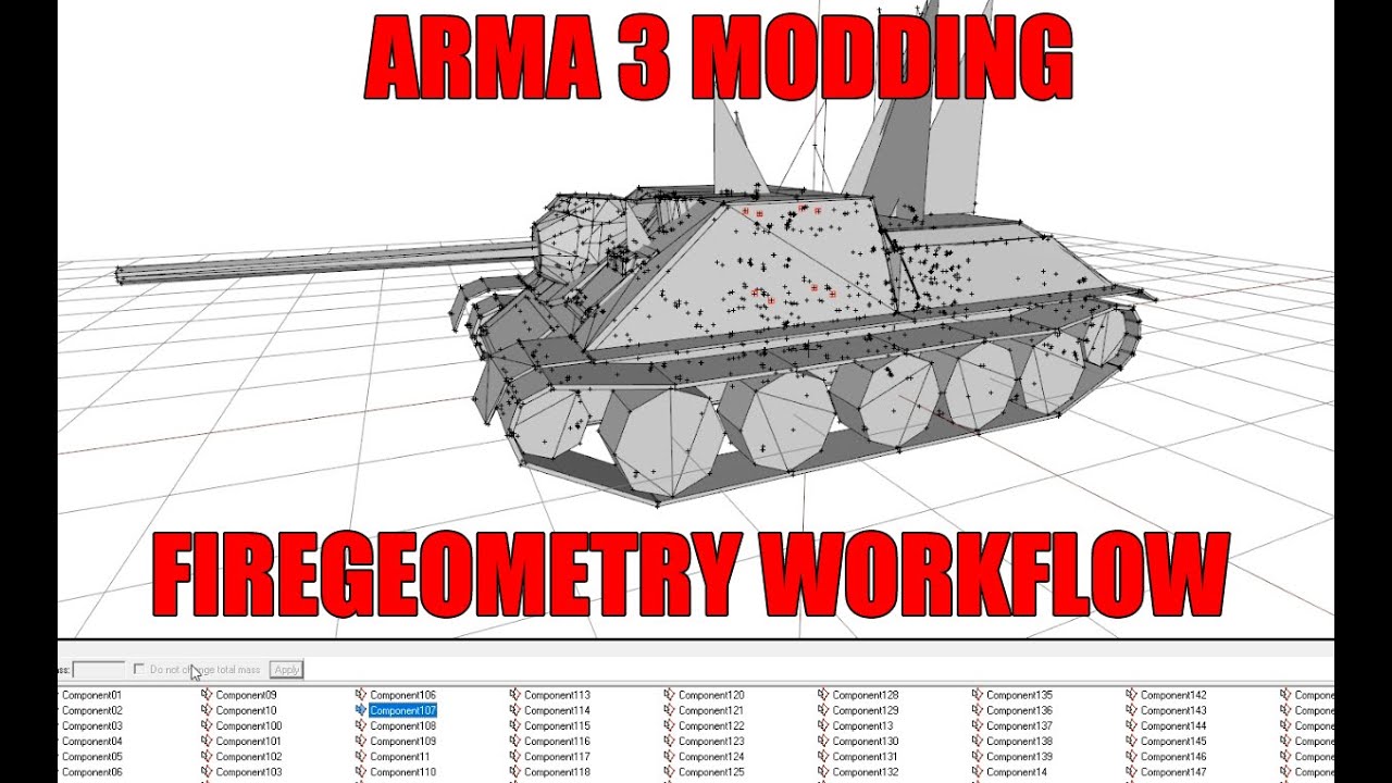
I wanted to explain to Bax the way I understand and work with Fire Geometry in Arma. So why not record it and share it with the community ?
Unfortunately OBS did not record Bax's voice. :(
The video is uncut so you will also notice that even with thousands hours in arma modding you can still lose your hair.
I could have done much cleaner ...
tough surge
tough surge
I have a question, does anyone know how I can add a loopcut in blender on 2 face...
please if someone knows
cedar jacinth
tough surge
please if someone knows
#YouTube mby?
marsh canyon
It does mean it is really simple Blender thing I guess
tough surge
what does mby mean
 woeful sluice
Where can I learn how to make a vehicle mod for Arma 3?
marsh canyon
Depenss on which kind of vehicle. But BIKI would be the best resort. And Arma 3 Samples as well
tough surge
marsh canyon
It does mean it is really simple Blender thing I guess
So I could find a solution for it in YT
Do you know any keywords I could search up to not be over specific
Or should I just search up with all the specifics
south badge
what do you mean on two faces at the same time?
Loop cuts only work with quad topology
tough surge
south badge
what do you mean on two faces at the same time?
I just looked it up on YT and i might be wording it wrong
So I saw a tutorial to only add a loop cut on a single face
And it says to select a face and press Y
To separate the faces
So I did, but when I tried to add a loop cut its only to one face
Rather than the normal loop cut which is on both faces
Now that I think of it
Could I not just merge the faces?
If thats an option
tough surge
tough surge
Could I not just merge the faces?
Or like link them (?)
south badge
selecting a face and pressing Y will cut the face off, no?
loop cuts are added via ctrl + r
tough surge
south badge
selecting a face and pressing Y will cut the face off, no?
I did it and it separated the faces
So I could add a loop cut only to those faces
But instead of mirroring like a normal loop cut that goes in the back and front
It only did it in 1 face
I could "merge" the faces(?)
I just thought about that
south badge
tough surge
It only did it in 1 face
I am really not sure I understand. A single face (plane) will always have the loop cut on both its front and back face.
tough surge
Ah wait
Youre right
I separated the faces
Therefore they arent connected I think
south badge
well, yeah
tough surge
Is there a way to add a loop cut to 2 specific faces then?
Or merge/link faces
Together
tough surge
tough surge
Is there a way to add a loop cut to 2 specific faces then?
Specific faces not necessarilly 2
Just a selection
south badge
I am unsure if I understand what you want, this is the best I could deduct, that you are trying to add a loop cut to two unconnected faces of a single mesh without the loop cuts being put on to the rest of the mesh
You can also add a loop cut that goes through the whole mesh and then ctrl-x to disolve the loop cuts on faces you dont want the loop cuts to be on
tough surge
south badge
I am unsure if I understand what you want, this is the best I could deduct, that...
Exactly
The problem is
The loop cuts wont be exactly on the same spot
Unlike if they were like connected
Theyd be placed in the same way
south badge
I reckon then you´ll have to move / slide the newly created vertices to get them in the correct position?
tough surge
Is there not an automatic way to do that
I will try and merge the faces and see if it works
Im wording this so badly 😢 🙏
south badge
It is easier to explain Blender stuff via a video
tough surge
south badge
It is easier to explain Blender stuff via a video <:yoba_zampolit:74988528584386...
ah yeah im sorry
i dont have obs set up
should probably get it working
cedar jacinth
You can also use the „Snipping Tool“ for that from Windows - works okay for stuff like this
cedar jacinth
tough surge
what does mby mean
Mby = maybe
 steep crest
Does anyone know how to make an object with two inventories?
storm wave
Cant see textures exept colors in 3d view buldozer in object builder
stuck oyster
tough surge
I will try and merge the faces and see if it works
Don't cut faces loop and merge back the new middle vertices have nothing to merge with and leave the edge open.
Use knife tool with middle snap
Or select faces, hide unselected, loop, unhide all
 bitter atlas
Good afternoon, I want to make a likeness of Ghillie. I roughly understood how the idea of inserting a texture without a background works. But I don't know how to arrange the texture according to the shape model, which would look voluminous and beautiful. Do you have any ideas about this?
marsh canyon
If you use Blender, basically this: https://www.youtube.com/watch?v=ic2ppLXS2xQ
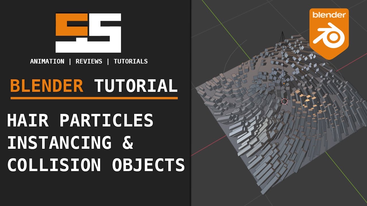
A neat little technique in using hair particles and instancing.
Follow me on Twitter: https://twitter.com/IdoineTutorials
Gumroad Membership and Downloads: https://gumroad.com/onlinerender
#blender #tutorial #particles
bitter atlas
Thanks
tough surge
Please if someone can tell me how I can do this thing right here, I've added loop cuts in the sections each way like that, but for some reason they don't create any faces and It's all glitched and buggy, I have to fill the faces myself and then It gets fixed(?) but for some reason its still "bugged" and there are multiple faces in the same spot or something like that, can someone please help me with this this has actually never happened to me before and I've done stuff like this before so I don't understand why it isn't working now
 stuck oyster
tough surge
Please if someone can tell me how I can do this thing right here, I've added loo...
stuck oyster
tough surge
Please if someone can tell me how I can do this thing right here, I've added loo...
make the base shape again
or try to merge the all the corner points together
if you cant properly manipulate it, you somehow messed the mesh
maybe each face is separated or somethin like that
stuck oyster
theres many different ways to make that shape I suppose
tough surge
Could I get some advise on how to make this please I've been struggling on this stuff for a while
I'm really new to blender
I never had these issues on the very few things I did before
I'm trying to get all the details
It all breaks when it comes to faces and vertices and that stuff
And that didn't use to happen to me
pallid nexus
tough surge
Please if someone can tell me how I can do this thing right here, I've added loo...
It might help to run cleanup mesh stuff on it (merge by distance and limited dissolve, to get rid of doubled vertices and stuff)
One method:
Loop cut to make the cuts
Edge slide the loops as needed
Extrude manifold to make the slots on one side
Symmetrize to match the other side
Different method is to work with boolean modifiers and multiple objects (or array modifier),
Non-destructive, but can get weird and slow with multiple batches of booleans
Watching one of the videos on topology can help
It's really easy to make topology that is painful to edit
tough surge
pallid nexus
It might help to run cleanup mesh stuff on it (merge by distance and limited dis...
Thats exactly what I tried on the last part, booleans
It was slow and I ended up running into a blockaide either way
It made vertices aswell
I think you cant
Make loop cuts
If theyre not 4 vertices
(I believe I might be wrong)
pallid nexus
Loop cuts I think expect rings of quads, a pentagon or a triangle will muck it up
But if you have an extruded hexagon as the start of the slide, loop cuts should work
Booleans can be slow to process, changing the mode of the boolean to fast instead of exact will make it much faster
Also, booleans and most other modifiers have a visibility toggle, and are not visible in edit mode by default
south badge
I think I would avoid booleans as much as possible, especially if you are new and can´t clean up the topology afterwards
tough surge
I am very bad at topology
But I'm trying to aim for such details in the faces
So I have to learn it eventually
For what I wanna do
I mess things up
Way too fast
pallid nexus
south badge
I think I would avoid booleans as much as possible, especially if you are new an...
Yeah, booleans can make ugly topology
Intersecting holes is one of the absolute worst to deal with (trying to make attachable muzzle brakes look good, and the UV is always hellish to deal with)
pallid nexus
tough surge
But I'm trying to aim for such details in the faces
If you can, plan ahead to how it will be UV mapped, since texturing in Arma is done almost entirely through UV mapped textures
south badge
I am not very good at Blender, I´d do it like this. But there´s 100 percent a faster way to do it for sure
tough surge
south badge
I am not very good at Blender, I´d do it like this. But there´s 100 percent a fa...
I have a question
How did you fill the faces quickly
And also
Dumb question but
How do you have the cubes be
Or mesh
be blue
That type of
Render
View
south badge
you can select the edges you want to fill and press F
that will fill in the space between the selected edges
or if you select two vertices and press F, it will create an edge between them
south badge
tough surge
Render
play around here with the things
 stuck oyster
less cleanup way would be just extrude the ridges out and then bevel the edge
but like I said many ways to make this
now here is my advice
just play around instead of trying to make something exact (or at least something complex) first
south badge
truee
stuck oyster
might add to the advice that even if you do something specific dont worry about failing with it
youll just got to try again with some different angle
elfin bone
How do I fix my shadows? http://puu.sh/mh8xS/44cec4f699.jpg

I've followed the LOD Guide
tough surge
stuck oyster
youll just got to try again with some different angle
yo
goat
r u up
nah its actually early
but r u busy
tklama is offline
stuck oyster
tough surge
nah its actually early
Im just going to sleep. But the channel expects you to just plop down the question you have and when people are around they might answer
elfin bone
Also my Geometry isn't working any advise?
elfin bone
Do shadows look alright or am I nit picking http://puu.sh/mhb2p/52065f9004.jpg
 cedar jacinth
How can i make this a convex hull without loosing the hatch shape? Its always "deleting" it...

 marsh canyon
It does mean you need to make multiple convex shapes
south badge
cedar jacinth
How can i make this a convex hull without loosing the hatch shape? Its always "d...
Create 4 components like this for example
 woeful viper
it won't get any better then this, that's for sure. What's the purpose of this pile of dirt?
stuck oyster
cedar jacinth
How can i make this a convex hull without loosing the hatch shape? Its always "d...
convex by definition can not have holes
this is important to remember
stuck oyster
theres lot of convex/concave difference explanations on the web if you want to find out more details
south badge
Just make it planar + no holes and you should be good
cedar jacinth
south badge
Just make it planar + no holes and you should be good
Well that would be problematic since the gap is for a hatch which is modeled and should be openend
woeful sluice
How can I make the 3D model usable in Arma 3, that is, in the game?
stuck oyster
woeful sluice
How can I make the 3D model usable in Arma 3, that is, in the game?
it is a bit big question thats not very simple to answer
what kind of model?
did you make it?
do you have experience with 3d modeling?
woeful sluice
stuck oyster
it is a bit big question thats not very simple to answer
There is a 3D model, someone else made it
south badge
cedar jacinth
Well that would be problematic since the gap is for a hatch which is modeled and...
There will be a gap obviously
You are making 4 separate rectangular components with a hole in the middle between them for the hatch
 prisma mulch
cedar jacinth
Well that would be problematic since the gap is for a hatch which is modeled and...
prisma mulch
cedar jacinth
Well that would be problematic since the gap is for a hatch which is modeled and...
Out of interest does anything actually need to pass through it?
Otherwise it could be fine to leave it sealed.