#arma3_model
1 messages · Page 32 of 1
 daring dagger
 stuck oyster
most likely wheel points are not set right so they are too big
daring dagger
currently adapting it from a sample someone sent me, so not that much of a shock
stuck oyster
the arma 3 sample car also has commented config
daring dagger
gotcha
daring dagger
when it comes to model.cfgs, what exactly is the difference between bones and selections? I'm assuming bones are things that move / are affected by animations and selections are more static things like Camo1 / Camo2 etc?
 marsh canyon
You can consider selection/sections are more of “set of polygon” to do something with it
daring dagger
marsh canyon
You can consider selection/sections are more of “set of polygon” to do something...
like hideable elements?
for example a spare tire on the back that could be removed in the virtual garage
stuck oyster
no
sections are split elements for material changes and rendering purposes
mainly related to texture/meterial related features
bones on the other hand move vertices of the model
and have nothing to do with textures etc
daring dagger
so Camo1 and Camo2 would be selections?
stuck oyster
selections are vertex groups that can be used in various ways
a bone targets selection named same as the bone --> bone name - "right_wheel" moves selection named "right_wheel"
and section targets a selection with same name
they are all parts of model the engine uses various ways
dont over think it
daring dagger
I am now lol
daring dagger
stuck oyster
a bone targets selection named same as the bone --> bone name - "right_wheel" mo...
can you just rephrase this, as I'm having trouble grasping what you're saying here
daring dagger
no worries, thanks for the clarification
 charred bolt
daring dagger
can you just rephrase this, as I'm having trouble grasping what you're saying he...
charred bolt
daring dagger
can you just rephrase this, as I'm having trouble grasping what you're saying he...
A named selection in the p3d mesh can be a bone in the skeleton (which can be moved or hidden), or it can be a section (used for changing textures or materials).
stuck oyster
piece of mesh can be part of both too 😄
daring dagger
charred bolt
A named selection in the p3d mesh can be a bone in the skeleton (which can be mo...
got it, thanks
charred bolt
You should always avoid having a named selection as both a bone AND a section.
But a piece of mesh can have more than one selection name.
daring dagger
do all selections in the p3d need to be defined as either a bone or selection in the model.cfg?
charred bolt
Strictly "no", you can have selection names that are not referenced anywhere.
 polar fiber
also there's a limit on the number of bones you can define anyway
charred bolt
255 bones max as long as you don't do anything funky with combined sections, which can reduce it further
daring dagger
got it, and the things defined in the cfg come from the memory layer of the p3d only?
or the whole thing?
charred bolt
Anywhere
daring dagger
or some combination
cool
I'm assuming if I reference one thing that is present in multiple layers it handles that itself
charred bolt
For example.
selectionDamage = "zbytek";
Then any res LOD with a selection name "zbytek" will be used in class Damage material swapping.
daring dagger
so yes
charred bolt
but you have to put "zbytek" in model.cfg sections[] too
daring dagger
cool, I kinda know what I'm doing now, thanks everyone
 still trail
qq about animations. Do you guys prefer to use min/max values with translations or begin/end? I ask as I understand min/max values impact animiation duration and that can cause it to mismatch with animperiod (for sounds)
 storm wedge
Running into issues with a uniform where the knuckles are going into the void, I thought it was just a selection or weight issue but I confirmed that they are weighted and selected in both blender and object builder. Also getting a similar issue at the foot but I assume its going to be the same issues. Anyone got any ideas?


 still trail
i.e animation duration where min/max is say 0 and 10 (moving something 10 meters) with animPeriod of 1 is around 10 seconds. But any sound would only play for 1 second (the animPeriod).
still trail
if you up the animperiod to say 10 seconds, the animation duration would go to 100 seconds lol
animation duration = max - min * animPeriod
would be better to use begin / end and set max and min to 1 - 0 and animperiod to 10.
that way sounds play for 10 seconds
and the animation duration will be 10 seconds
Thoughts?
storm wedge
Model cfg looks fine and pboproject built it out with no complaints, ill try blending the weights and seeing if that fixes it
stuck oyster
you might have few vertices missing from the selection
 umbral shuttle
I am assuming object builder issue, when aiming down sights its offset like that, not sure why. in geo lod I have autocenter = 0, not sure what else to have.

 marsh canyon
Do you have LOD 0, but as well as Pilot LOD?
umbral shuttle
yes res lod 0 and view pilot are present and the exact same
 marsh canyon
🤔 How do you debug it, diag_resetShapes or repack?
umbral shuttle
marsh canyon
🤔 How do you debug it, `diag_resetShapes` or repack?
repack and try in game 🙂
pbo only takes 2 seconds to build 🙂
sorry for the terrible screenshot (alt tabbing makes the camera move away), but the bullets are coming out wrong too  maybe I got the othet memroyt points wrong

im going to cry

 mossy mulch
are you sure youre not looking at one of the edit lods
mossy mulch
umbral shuttle
im going to cry
its tactical

 sour bough
umbral shuttle
sorry for the terrible screenshot (alt tabbing makes the camera move away), but ...
sour bough
umbral shuttle
sorry for the terrible screenshot (alt tabbing makes the camera move away), but ...
Make sure your usti and konec hlavnes are lined up properly
 tacit karma
sour bough
tacit karma
sour bough
lmao
umbral shuttle
sour bough
Make sure your usti and konec hlavnes are lined up properly
so yeah so wat accidently happened is I had the end position for bolt axis selected 
sour bough
umbral shuttle
so yeah so wat accidently happened is I had the end position for bolt axis selec...
that was some weather, huh
umbral shuttle
yeah it be like that
 tropic geyser
Does anyone know of a finished or WIP ZSU-57-2?
 lone robin
I’ve got the blender set up working, I’ve ran into a weird issue I’ve been trying to figure out all morning which is one of the objects is assigned the wrong texture in blender even though it’s color on the mask is associated with another. Any pointers as to what I can do to correct that ?
stuck oyster
lone robin
I’ve got the blender set up working, I’ve ran into a weird issue I’ve been tryin...
are the colors mixed?
lone robin
stuck oyster
are the colors mixed?
The object in question is red on the mask but it is slightly blended with another red object but it’s not mixed with green or blue
stuck oyster
can you post pictures of that. im not quite sure what you mean
 granite sleet
Hello, I've started updating my backpack mode a bit, I stopped 2 years ago. So I did as usual and wanting to see the final result of my latest addition, he did this to me. I don't understand at all where this comes from while for the others I did the same. THANKS
 stuck oyster
granite sleet
Hello, I've started updating my backpack mode a bit, I stopped 2 years ago. So I...
stuck oyster
granite sleet
Hello, I've started updating my backpack mode a bit, I stopped 2 years ago. So I...
requirements are a basically same as with a helmet. just different weighting selection
see pins for headgear tip
 short marsh
https://www.youtube.com/watch?v=_585UHq_wB0 I've had this issue in my SUV and trying to figure out what to do. I messed with the Physx settings to see if that was the issue, but since it's a port I don't know how to keep it from doing this.

I'm trying out new things, and that's doing a car. Right now I'm porting it from an Arma 2 model, just to get things setup correctly. But I'm running into this problem, and don't know how to fix it.
stuck oyster
short marsh
https://www.youtube.com/watch?v=_585UHq_wB0 I've had this issue in my SUV and t...
wheres your mass center?
short marsh
That's a good question, I don't know
stuck oyster
OB shows it in geometry lod when you select all mesh and turn off DX drawmode
there should be a blue cross
short marsh
Yeah I found it, it's in the middle, I'll try the front view
stuck oyster
for a car you want it to be pretty low
so youll have adjust how your mass on the points is distributed
short marsh
Okay how do I move it?
stuck oyster
for example select the bottom points and youll see the mass dialog give it some amount
short marsh
Right
stuck oyster
replace that with triple the amount
when do not change total mass is enabled, it will adjust the other unselected points accordingly
another way is to have relatively low general mass and then have separate mass components
that you can move around
the sample helicopter has those adjuster cubes
short marsh
Ahh so the car needs those too?
stuck oyster
 short marsh
I don't have those on my car
stuck oyster
not necessarily they can just be used to fine tune the mass center more easily than adjusting the other point weights
actually sample car has these too

and the mass center is around wheel center level
bit towards the front as it would be
short marsh
Okay I must have missed them. The trick you stated worked perfectly, vehicle moves as it should, and I'll move those cubes to the car after looking at the model
stuck oyster
just remember to regen component names
short marsh
Okay, will do
short marsh
Now the car is drifting at high speed when I turn, is that still a geometry issue?
Or is that just how it works with the settings? Like most vehicles of course do not drift of course, so what else I must do.
lone robin
stuck oyster
can you post pictures of that. im not quite sure what you mean
None of the other arches at the top have this issue either
 stuck oyster
Dont really know why it would do that
lone robin
stuck oyster
Dont really know why it would do that
I guess I’ll try to remake my mask and see if that works
stuck oyster
could be its not pure red I suppose
you can try altering the nodes and how it blends
daring dagger
any idea if this is physX or model related?
this is an old clip from a couple hours back, but it still acts very similarly, when it comes to a rest it also sits on it's front
 stuck oyster
physx wheels still broken?
too many of them?
wheel defining points not named right? not present?
daring dagger
I have 4 wheels and copied over the wheel bounds from the sample and alligned them with the bottom of the wheels on the model
same with land contact
stuck oyster
did you get the wheel centers
daring dagger
defined wheel_1_1 wheel_1_2 wheel_2_1 and wheel 2_2
daring dagger
stuck oyster
did you get the wheel centers
let me check
i have axis, bound, steering and steering_axis
in the memory points
am I missing something?
daring dagger
daring dagger
i have axis, bound, steering and steering_axis
and for the back wheels I have axis and bound only
stuck oyster
sounds like you should have right parts there
 daring dagger
appear to
 daring dagger
stuck oyster
sounds like you should have right parts there
daring dagger
stuck oyster
sounds like you should have right parts there
is this config in the samples? It's not there for me
 daring dagger
verifying my files now
yeah it's there now
just discovered I was missing the "posun wheel" axes, will implement them and see if that fixes the issue
daring dagger
daring dagger
just discovered I was missing the "posun wheel" axes, will implement them and se...
still happening
lone robin
stuck oyster
could be its not pure red I suppose
I figured it out, I;m just an idiot. One more question then I'll go quiet until I'm stuck again lol, whats the purpose for there being two material slots in the example ? could a second material slot set up like in the example be used to do the interior or would that not be smart to do in the same scene as the exterior ?
stuck oyster
lone robin
I figured it out, I;m just an idiot. One more question then I'll go quiet until ...
its just example of the possiblity of using multiple multimaterials to increase number of surface types
charred bolt
daring dagger
still happening
Set Geometry LOD mass to correct value (kg).
Ensure Centre of Gravity is midway between wheels and above axle height.
Confirm you have a simple Geometry Phys LOD and no wheels in that LOD.
Geometry LODs contain objects that are closed, convex and named ComponentNN.
Check in class Wheels that the total sprungMass for the 4 wheels matches the Geometry LOD mass.
Check that springStrength is around 25 to 100x sprungMass.
Check in Buldozer that the wheels move upwards (compress) as damper source goes from 0 to 1 (all 4).
What values have you set for:
- maxDroop, maxCompression?
- offset0 and offset1 in the damper translation animation?
- distance between the damper axis memory points?
daring dagger
charred bolt
Set Geometry LOD mass to correct value (kg).
Ensure Centre of Gravity is midway ...
1.Done
2.Done
3.Done
4.Done
5.Done
6.Testing
7. How would I check the dampers in Bulldozer?
stuck oyster
test that the damper source moves all wheels at same direction
charred bolt
In Buldozer cycle through animationSources, mouse wheel to change values
You mentioned "posun" for wheel axis memory points, but in config you've called them "wheel_axis_x_x"
daring dagger
currently buldozer finds no animations, so I'm going to have to go and fix that
charred bolt
Check model.cfg class name of vehicle matches p3d file name
daring dagger
I changed it to match and now I get this
 charred bolt
Post model.cfg? Use pastebin
daring dagger
looking at it I may have overwritten / deleted my skeleton
maybe 2am isn't the optimal time for this
I'll probably come back to it tomorrow
yeah I've overwritten the skeleton at somepoint
daring dagger
hmm
I think something might be off about this
I'm assuming either my axis are skewed I'm using the wrong one
I'll take a look tomorrow
got the dampers working, will test in game real quick to see if that solved it
maybe not

but atleast I've made some progress compared to the last few days, thank you again everyone
 cloud zealot
I'm working on a concept submarine. What if i have 4 propellers on the same ship ? Can i have hitEngine1, hitEngine2 etc..... for the hitpoints ? Can i have the destruction of one engine affecting the capacities of the ship ?
stuck oyster
maybe via scripting
but I for the sim types I think engine is singular entity even if it had multiple hitpoints affecting it
charred bolt
cloud zealot
I'm working on a concept submarine. What if i have 4 propellers on the same ship...
Yes probably. Check out the C-119 aircraft in our SOG Nickel Steel mod for how it's done.
 restive pond
im trying to assign the LIM-85 ammo box as the magazine in a magazine proxy but it doesn't show in-game?
meanwhile, the proxy works just fine if i assign it as a regular 5.56 magazine
essentially, im trying to create my own machinegun model, but using the LIM-85 ammobox as a proxy magazine
I'm not sure if it works for machineguns or not (since the ammobox has its own animation when shooting, compared to a standard magazine)?
 boreal jolt
30Rnd STANAGs work fine because they do have a modelSpecial (mag_556x45_stanag_30rnd.p3d).
The LIM-85's model (lmg_03_f.p3d) on the other hand doesn't use magazine proxies. The ammobox is a part of the model itself and is not a standalone model that you can define in a magazine's modelSpecial.
You'll need to make your own model for it or grab one from an open source (A2 Samples, NIArms, etc.).
restive pond
ah ok, i never knew NIArms was actually open source...
thats a bummer with the proxy though but thanks
just to make sure, with NIArms since its open source you dont need to make it as a workshop requirement right?
lone robin
For assigning the arma texture in blender, since I'm using a multimaterial would assigning just the multi.rvmat in the materials tab be appropriate or is assigning a paa in the face texture also needed ?
stuck oyster
no paa needed
 hollow fulcrum
@still trail i generally use points for translation things
 tribal rain
so this is a question thats been going on around my head for a while now the various memory points we use for our mod creations what language is that?
Asking as it would be super easy to know what "konecHlavlen"etc etc means im not asking for a full translation just a start of it is this ...... language. then i can go and go and figure out the rest on my own.
 inland pawn
tribal rain
so this is a question thats been going on around my head for a while now the var...
inland pawn
tribal rain
so this is a question thats been going on around my head for a while now the var...
BI is a Czech based company. A lot of variables and names are in Czech
 stuck oyster
tribal rain
so this is a question thats been going on around my head for a while now the var...
stuck oyster
tribal rain
so this is a question thats been going on around my head for a while now the var...
however all of them can be changed to whatever you define them to be in the config
hollow fulcrum
@Redphoenix ermm.. i just grab it like any other window. i have a few monitors though, so grabbing it is pretty trivial. its position though, is either in a config/ini or registry though i imagine. deleting relative foo would probably return it.
charred bolt
tribal rain
so this is a question thats been going on around my head for a while now the var...
Most of them can be found translated to English here:
https://community.bistudio.com/wiki/ArmA:_Armed_Assault:_Selection_Translations
but as a modder you soon get fluent and used to using the Czech names until it's second nature, but I'm quite sure we all butcher the pronunciations.
tribal rain
charred bolt
Most of them can be found translated to English here:
https://community.bistudio...
thanks this will deffo come in handy
 quick terrace
shift space m i believe should work
lone robin
For working multimats for the interior of a building, understanding it needs two uv sets the only way I can comprehend it working in blender is to copy the objects into a new group and use those to work on the interior. Is that going to work or is there any other way I should be doing this ? The initial way I was going about it was just going to the objects that have exterior multimat applied and adding 2 more UVs for inner but it seemed the adjusts I made for those UVs affected my exterior MM and Bake UVs
boreal jolt
restive pond
just to make sure, with NIArms since its open source you dont need to make it as...
You can grab the source files directly from toadie's Github:
https://github.com/toadie2k/NIArms
Licencing falls under APL-NC-SA so follow the usual rules:
- Your mod must also be APL-SA (or at least part of the mod that specifically uses the model)
- Credit to toadie + the original creator of the model if toadie explicitly said that it wasn't made by them
- Link to original sources wherever you took the model from (whether it's the Github or the NIArms Workshop page)
- No monetisation
https://forums.bohemia.net/forums/topic/163106-toadies-smallarms-and-animations-for-arma3/
#159592166778339328 message
stuck oyster
lone robin
For working multimats for the interior of a building, understanding it needs two...
you must not make more uvsets than 2
the 2 are shared accross all materials
lone robin
stuck oyster
the 2 are shared accross all materials
Got it, thank you
cloud zealot
charred bolt
Yes probably. Check out the C-119 aircraft in our SOG Nickel Steel mod for how i...
I will take loot at it
 trim abyss
Hey, got a question about the _nohq texture layout
_nohq (normal map high quality)
- Red Channel (Y+ ?)
- Green Channel (X- ?)
- Blue Channel (Unsure?)
What exactly goes into the channels?
Been searching around but can't find much about the specifics
marsh canyon
It should be the same with DirectX's normal specification
trim abyss
Hmm, for that its usually X in red, Y in green, Z in blue
But for arma it seems to be Y in red, X in green, maybe Z in blue? but also can't tell if they're positive or negative
marsh canyon
Kinda wanted to see the nohq, expected result and actual result becaute I've never experienced issue with nohq like that
trim abyss
Its not so much as an issue, as it is a question of how it works in arma
Polarity of axis is a completely normal thing, but for some reason there's zero documentation on it for arma
trim abyss
Got it
https://community.bistudio.com/wiki/RVMAT_basics
I must have missed that a million times, jfc
_nohq (Normal Map High Quality) (DirectX Tangent-Space Maps, same as Unreal Engine and 3DSMax Renderer Default Setting)
- Red Channel (X+)
- Green Channel (Y-)
- Blue Channel (Z+)
Now I just need to find out how to do emissives and I'm set
charred bolt
trim abyss
Now I just need to find out how to do emissives and I'm set
In the Super Shader rvmat, emmisive[]={0.1,0.2,0.3,1};
format R,G,B,1
trim abyss
Does it require a specific emissive texture?
charred bolt
No, but it would be normal to use a green colour if you wanted a green glow etc
They're often applied to an overlay selection that is hidden by default, and switched on at night, such as instrument panels.
trim abyss
I'm unsure how it knows what part of the texture (and which texture its using) to define emissive areas =s
Is the RGB value you put in the color it overlays in the _co texture? (ie, only green of that value will be an emissive)
charred bolt
Each face in the model mesh is assigned a texture (co, ca) and material rvmat - the rvmat maps the nohq, smdi, as, but also sets the specularity power, emissive, environmental reflections.
So for an emissive overlay, you'd typically create a new transparent texture for most emissives on the object, to which you can apply a custom rvmat.
trim abyss
Will give that a shot, thankyou!
Is the ImagetoPAA converter meant to fail on _nohq png textures?
marsh canyon
Nope, it should work if the png is in correct format, no matter which suffix it is
trim abyss

charred bolt
pixels to power of 2
marsh canyon
But if you mean same file, different suffix...
trim abyss
Its 1024 x 1024, all the other textures were converted, not sure why _nohq isn't working =s
 charred bolt
What do you think is wrong with it?
trim abyss
Fail to process armageddon_NOHQ
Failed to convert 1 file(s)
Won't tell me why
charred bolt
What bit depth?
trim abyss
64, That would be why
restive pond
when I try to import .p3d from arma 3 samples this shows, and only the LOD 1 appears
 trim abyss
Can't seem to get it into the game, comes up as a prop but no mesh/textures
Everything should be set up right
Anyone able to take a look?
marsh canyon
How do you check it ingame? Or on Buldozer?
trim abyss
Editor > vr map, in-game
marsh canyon
What if in Buldozer?
trim abyss
I didn't know it was a thing, haven't used it =s
marsh canyon
Open P3D in OB, click OFP icon
trim abyss
I don't see it =s
 marsh canyon

trim abyss
 trim abyss
Hmm, I seem to have set it up right (with the arma3.exe), starts up just fine but results in a gray screen
charred bolt
trim abyss
Hmm, I seem to have set it up right (with the arma3.exe), starts up just fine bu...
Does the CfgModels class name in model.cfg exactly match the p3d name, which is in the same folder?
trim abyss
In objectbuilder or the mod folder?
charred bolt
What is the file name of your p3d model?
What is the class name you are using in model.cfg (CfgModels)?
trim abyss
Armageddon.p3d
That's the only config file I'm using
Mod folder is "@Cyno Test", addon pbo is called "CYNO_AMARR_Armageddon"
charred bolt
Do you have a model.cfg file?
trim abyss
I do not =s
trim abyss
Hmm, trying to follow what the Fist of Steel mod did
It only had that file in it in that style
Keeping in mind this is only for a prop
charred bolt
Take a look at Arma 3 Samples / Test_Lamp_01 for how to do a prop
trim abyss
Thankyou, will do!
stuck oyster
trim abyss
Armageddon.p3d
That's the only config file I'm using
Mod folder is "@Cyno Test",...
since ot seems you rae making something in the EVE universe, this is a self made model? not ripped from the game?
charred bolt
trim abyss
Hmm, trying to follow what the Fist of Steel mod did
It only had that file in it...
 trim abyss
Its imported from EVE
CCP released a content creators agreement that allows it since 2020
This isn't my first project: https://www.moddb.com/mods/sins-of-new-eden-rebirth
ModDB
After a long, long slumber. Sins of New Eden has returned with more experience, knowledge and passion for bringing just a slice of the beauty and thrill from EVE Online to Sins of a Solar Empire: Rebellion.
Ahhhhh, Fist of Steel used the Test_House_01 as a reference
charred bolt
trim abyss
Ahhhhh, Fist of Steel used the Test_House_01 as a reference
Well, that also has a model.cfg
trim abyss
This is all it has
charred bolt
Test_House_01 has a model.cfg
stuck oyster
for model without animations, model.cfg is not needed
like a rock would not have one
charred bolt
Not sure about that - you need it for section swapping too
trim abyss
Ahhh
stuck oyster
charred bolt
Not sure about that - you need it for section swapping too
rocks dont have that either
but yes sections need it too
so anything with hiddenselections or using some engine feature that uses sections needs model.cfg too
charred bolt
Merely pointing out that the sample he referenced, and the prop sample I referenced by BI, both have model.cfg
trim abyss
I don't think its that, that's causing the issue come to think of it
Might just be references
Updated references and still nothing 
When importing fbx, are you meant to select master scale 0.01 or 0.001?
 trim abyss
I guess one up from that lmao
What was wrong with it? not even that showed up for me
charred bolt
trim abyss
I guess one up from that lmao
What was wrong with it? not even that showed up f...
Added missing CfgPatches entries.
Corrected bad paths of texture and rvmat in p3d


Don't use ALL_CAPITALS for class names, they should be reserved for MACRO's in #defines.
So change class AMARR to class Cyno_Amarr, which then matches your Units[] entry.
charred bolt
trim abyss
How do you access the texture / rvmat stuff?
Window/Resource Library
RMB on texture or rvmat
trim abyss
Do you just need to define the _co per mesh group in that UI?
daring dagger
back again, I've got the car pretty much functional now but it has a weird tilit to the rear right wheel, I'm assuming this is something physX spring related?

also it veers to the right when driving straight
charred bolt
daring dagger
also it veers to the right when driving straight
Post config.cpp class Wheels, model.cfg wheel/damper code, isometric view of p3d Memory LOD with wheel centre/axis/boundary and damper points, with selection names.
daring dagger
gimme a second

should be noted that I apparently have wheel_x_x_axis mem points and posun wheel_x_x points, not sure if that is something I should get rid of
daring dagger
daring dagger
this image contains all the posun and axis points selected, if you want some more images with individual components selected or something let me know
charred bolt
daring dagger
should be noted that I apparently have ``wheel_x_x_axis`` mem points and ``posun...
The answer to that is here
 daring dagger
so should I have both or not?
charred bolt
Except you then use the other one in model.cfg for the animation.
I'd only have one "wheel_1_1_axis"
daring dagger
gotcha, not sure how I ended up with both
charred bolt
So delete your posun selections. Make sure each wheel has a wheel_x_x_axis and wheel_x_x_bound
Change the class Wheels config to use the axis names
Change any occurences in model.cfg of posun too
Does your suspension go straight up and down?
daring dagger
I think so, let me double check
charred bolt
daring dagger
I think so, let me double check
If so, suspTravelDirection[] = {0,-1,0};
Please also show front view of car in Memory LOD with wheel axis and bound points
daring dagger
also found out that my posun points are on the vertical as opposed to the wheel axis points that are horizontal, which do I want here?

 daring dagger
charred bolt
Please also show front view of car in Memory LOD with wheel axis and bound point...
daring dagger
charred bolt
Please also show front view of car in Memory LOD with wheel axis and bound point...
will get that for you now
here are the bounds, you can see the axis points in one of the previous images
 charred bolt

wheel_x_x_axis is the axis of rotation for each wheel (horizontal)
wheel_x_x_steering_axis is the axis of rotation for the steering on each wheel (vertical)
daring dagger
so my posun axises are acting as steering axes, which I already have
so I'll delete them
charred bolt
Your total mass in Geometry LOD is 2400kg?
charred bolt
Try
springDamperRate = 8485;```How do you define the rvmat? holding right click over it doesn't bring up the reference prompt
charred bolt
Also we need to know the distance between your damper axis points.
As maxDroop (and maxCompression) need to be equal to damper offset0 * axis length (and damper offset1 * axis length)
charred bolt
trim abyss
How do you define the rvmat? holding right click over it doesn't bring up the re...
Select all the faces in your model which should have the rvmat applied.
Press E.
Browse to rvmat under Material box.
trim abyss
Ah ha, thankyou!
daring dagger
not a lot of difference

although both back wheels now touch the ground
now veers to the left
charred bolt
refer to last question
charred bolt
daring dagger
now veers to the left
Do you want a voice call/screen share to work through it?
trim abyss
charred bolt
Added missing CfgPatches entries.
Corrected bad paths of texture and rvmat in p3...
(No rush, don't mind me atm)
Did the rvmat thing, the texture reference, it shows in buldozer, but not in-game and I have no idea why
I updated the config to be the same as this, still nothing
charred bolt
trim abyss
(No rush, don't mind me atm)
Did the rvmat thing, the texture reference, it sho...
You have a p: drive?
What are you packing into a pbo with?
trim abyss
This is the folder I'm packing into a pbo (not zipped of course)
charred bolt
What software are you creating the pbo with?
charred bolt
ok, that's highly not recommended
trim abyss
Oh
Is there something else I should be using? that one was recommended by another arma modder
charred bolt
I use Mikero tools https://wiki.mikero.tools/

Majority of modders are probably using mikero pboProject (free and paid versions).
Some are using HEMTT - ok if you prefer command line to gui
Best not to use BI's AddonBuilder as it doesn't contain much in the way of error checking.
Definitely don't use Pbo Manager.
trim abyss
Ahhhhh alright, thankyou!
charred bolt
I was able to fix your project in a few minutes because pboProject told me what was wrong with it during build.
plus I have a little experience 😉
trim abyss
Both seem to help alot haha, uninstalling pbo manager now
charred bolt
If you're feeling brave there's the "Mikero AiO" all in one installer which can help newcomers get started.
trim abyss
Hmm, running it, coming up with "Missing file Armageddon.p3d"
But its there
trim abyss
Yeah I have no clue why its doing that, will try more in the morning 🙃
charred bolt
I fixed that... Needed a backslash \ at start of path from memory
trim abyss
You can't input custom paths though, you need to physically go for it? (like hunt for the folder)
 charred bolt
You should be building from P:\Cyno_Test
(not 100% sure if it matters but I always have done)
 finite stump
How do I code in the ability to use custom textures like on the vanilla white boards and billboards?
trim abyss
charred bolt
You should be building from P:\Cyno_Test
(not 100% sure if it matters but I alwa...
It shouldn't matter which drive, also don't have a P: drive
I reinstalled it and it was still trying to pack a folder in a different location, think the settings are fucked
 storm wave
 trim abyss
Apollo, you able to pack this into a pbo?
trim abyss
Or does it say missing file
charred bolt
trim abyss
Or does it say missing file
If you're not using a p: drive I can't help you further, sorry.
charred bolt
storm wave
Make sure you don't have any ngons. Triangles and Quads only, no degenerated faces.
storm wave
what does it mean
marsh canyon
N-gons are polygon but it has more vertices than four
trim abyss
charred bolt
If you're not using a p: drive I can't help you further, sorry.
A drive using the letter P isn't a requirement for using pboProject

 celest arch
S.O.S. and noob alert
I'm trying to animate this thing: http://i.imgur.com/02pK4Gf.png
the cogs and front harvester rotate, they follow the wheels of course
problem is when I try to raise the whole thing: http://i.imgur.com/Dlh9yQ1.png
parts that rotate with wheels wont follow the animation, even if they're in the same named selection
 jaunty rune
are the armas one object?
celest arch
I have a named selection named A for the whole harvester part, a selection named B for the front spinning part (with its own axis), and a sel named C for the back cogs
celest arch
http://i.imgur.com/7uDaxur.png <<< selection "A"
I'm fairly sure it's something obvious, looks like the wheel rotation anim takes priority
jaunty rune
dont have much exereance or knolage of what is working and whats not but my guess is its taking the belt and thiking it is part of the outter wheel
celest arch
mmmmm I think I cant follow you
jaunty rune
the hole belt and arms spin with the wheels correct?
celest arch
no just selections B and C
and thats correct, but I wanted a second animation to raise the whole thing up (A), while still spinning B and C
jaunty rune
im refering to what acctualy happens when the car moves
oooo
ok i think i under stand now
celest arch
didnt try in game, but from buldozer the wheel rotation is fine
jaunty rune
you want the front cog to move up with the other one
jaunty rune
my best guess is that one is taking priority over the other and maby try them in one section not sure tho i havn't messed with cars to much before
celest arch
yeah that was my guess
"wheel" gets priority
can't try them in the same section, as I dont want my arms to spin with wheels
jaunty rune
ya that would be interesting
celest arch
lol that would be transformers :D
jaunty rune
would be sick would just through cars
 foggy finch
do it and load in terrain on a slope and fire it up :D
jaunty rune
could you include it in bought?
jaunty rune
the secontion you use to controll the lifting could you include the frount cog in that aswell as in b
celest arch
it's there already
jaunty rune
o ok, then im out of ideas
celest arch
the "arms lifting" animation affects selection "A" which includes "B" and "C" (moving parts) + all the non-moving parts
but just the non-moving parts actually gets animated
I'm out of ideas too, but its midnight, didnt get dinner, I might need a fresh mind
hollow fulcrum
either the bone structure is not proper or the selections are dorked up a bit.
celest arch
I call the bone problem... triple checked selections, they're fine I made them in Blender
hollow fulcrum
it's one of the two if everything else is doing as it should.
celest arch
"addon_trebbia","",
"cogs_rear","",
"cogs_front",""
this is inside class Car : Vehicle {
skeletonBones[]=
cogs_rear and cogs_front are the spinning parts
should I link them to addon_trebbia which is the whole part?
ah fuck yes
hollow fulcrum
👍
hollow fulcrum
glad it was easy :D
restive pond
my vehicle's hull is not getting damaged at all? firegeometry and hitpoints are set and they are connected in HitPoints class in the config. Meanwhile, the fuel and engine hitpoints work just fine...

this is the karoserie and hit_hull_point selections ^
        {
            class HitLFWheel: HitLFWheel
            {
                radius = 0.33;
                visual = "wheel_1_1_damage";
                armor = -250;
                minimalHit = -0.016;
                explosionShielding = 4;
                passThrough = 0; /// it is easier to destroy wheels than hull of the vehicle
            };
            class HitLF2Wheel: HitLF2Wheel
            {
                radius = 0.33;
                visual = "wheel_1_2_damage";
                armor = -250;
                minimalHit = -0.016;
                explosionShielding = 4;
                passThrough = 0;
            };
            class HitRFWheel: HitRFWheel
            {
                radius = 0.33;
                visual = "wheel_2_1_damage";
                armor = -250;
                minimalHit = -0.016;
                explosionShielding = 4;
                passThrough = 0;
            };
            class HitRF2Wheel: HitRF2Wheel
            {
                radius = 0.33;
                visual = "wheel_2_2_damage";
                armor = -250;
                minimalHit = -0.016;
                explosionShielding = 4;
                passThrough = 0;
            };

            class HitFuel
            {
                armor = 0.5;
                material = -1;
                armorComponent = "hit_fuel";
                name = "palivo";
                visual = "-";
                passThrough = 0.5;
                minimalHit = 0.2;
                explosionShielding = 0.2;
                radius = 0.25;
            };
            class HitEngine
            {
                armor = 0.5;
                material = -1;
                armorComponent = "hit_engine";
                name = "motor";
                visual = "-";
                passThrough = 0.3;
                minimalHit = 0.2;
                explosionShielding = 0.2;
                radius = 0.45;
            };
            class HitBody
            {
                armor = 0.5;
                material = -1;
                name = "karoserie";
                visual = "zbytek";
                passThrough = 1.0;
                minimalHit = 0.01;
                explosionShielding = 1.5;
                radius = 0.45;
            };
            class HitHull
            {
                armor = 0.5;
                material = -1;
                armorComponent = "hit_hull";
                name = "hit_hull_point";
                visual = "-";
                passThrough = 0.5;
                minimalHit = 1;
                explosionShielding = 0.1;
                radius = 0.25;
            };

            class HitGlass1: HitGlass1 {armor=0.25;}; /// it is pretty easy to puncture the glass but not so easy to remove it
            class HitGlass2: HitGlass2 {armor=0.25;};
            class HitGlass3: HitGlass3 {armor=0.25;};
            class HitGlass4: HitGlass4 {armor=0.25;};
};```the material for the hull is metal_plate_thin.rvmat
 bright echo
minimalHit seems very high on hithull
restive pond
got it, thanks
celest arch
one more question: can I assign a sound to one of my useractions?
hollow fulcrum
ermm.. yeah, how though im not sure what the best method is currently (there are inconsistencies and whatnot i think) i gave up on keeping up with sounds a couple years ago. 😕
then again, maybe they fixed all that and locality things are good.
celest arch
wait maybe I should take a look at the cargo heli ramp
hollow fulcrum
^^ never hurts
celest arch
I also have another question if you don't mind :)
I think since the Heli DLC, if you get close to a tail rotor while it's spinning you get squished. What does control that feature?
or is it just a detailed geolod section?
hollow fulcrum
not sure
lone robin
are there any tricks that Im missing for baking my interior AO ? the rendered view looks fine but the baked map is pretty much black regardless of what I do
 celest arch
yeah well, I said its fixed too early
worked fine in Buldozer, but when I try it in game cogs dont spin with wheels
the whole thing raises though, but it seems to be ignoring animperiod 10 as it's an instant transition
I'll continue tomorrow, thanks again Hatchet and Bayeball
stuck oyster
is the interior mesh facing righ way?
as in do you have backface culling enabled?
so you see which way of face is front
hollow fulcrum
aye, sorry.. trying to close out the business part of the day here. that sounds a little more 'config' issue'ish there.
lone robin
stuck oyster
is the interior mesh facing righ way?
Even with backface culling enabled it’s still baking black in the same objects
lone robin
stuck oyster
do you have multiple objects in the scene?
All the walls, ceiling, and floor are separate objects
stuck oyster
lone robin
All the walls, ceiling, and floor are separate objects
but are there duplicates
check if theres any tips on rendering AO and why it comes black on the web
I've seen this before but cant remember exactly what it was
so Im fairly sure you might find something online
lone robin
stuck oyster
but are there duplicates
No duplicates in the active scene.
Thank you
 lament marlin
hey guys, is there a uniform template sample somewhere? can't find one in samples
with configs and 3d models and textures
quick terrace
what do you mean by "uniform"
there is a character sample
and a vest sample
and template
 north sundial
Shultz please tell me you plan on adding a script to that to make it so you run people over and dice them up
haha
lament marlin
well uniform, how do i describe it, thing that you can add to a character by calling addUniform "classname"
lament marlin
as i understand it it's a completely new model for the whole body every time
quick terrace
yeah no, there is no such thing
precisely because there is no such uniform
as an independent mesh from the half-naked body sample file provided already
but yes, a new mesh together with the "uniform"
lament marlin
okay so i build a model around that sample and add it to a game?
quick terrace
precisely
lament marlin
thanks alot
trim abyss
When exporting a mesh, are you meant to select the "P3D Old Version" option in object builder? Or a different format (assuming there's a newer version we should be using thats just named something else)
trim abyss
Trying to figure out what might be wrong with my mesh implementation
trim abyss
trim abyss
When exporting a mesh, are you meant to select the "P3D Old Version" option in o...
Anyone able to answer this?
Its not listed on the wiki
marsh canyon
Because we're more confused what is the situation or even software there
marsh canyon
Because, since you're using OB, you already got the P3D?
Which makes the word or act "export" there, urm, confusing
trim abyss
When exporting a mesh- in object builder
You import as fbx, export as p3d
But it lists "old version" next to p3d, implying that there's a new version somewhere else, that might be called something else?
I'm not sure how else to elaborate on it, if its not being misread
marsh canyon
Urm, first thing first, what OB uses is P3D. And Old Version of it, AFAIK, is referring to OFP's format. In order to make an A3 asset, what you got already, is THE P3D already, if I solve my confusion properly
trim abyss
I'm making the p3d in object builder, I'm not exporting it into object builder from another program as a p3d, I'm straight up importing an fbx into object builder
If the export option "P3D - Old Version" is fine, then I'm not sure how or why its being corrupted during export
Its not being accepted by mikero's pboProject for binerizing, meaning the meshes format (or something else) is invalid, hence the question
marsh canyon
Okay uh, had to ask, do you do Blender? Or any other 3D model software?
trim abyss
I have blender but not much experience in it, usually leave that up to my team members
Is there a process that needs to be followed before importing it into object builder?
marsh canyon
Okay that is your first failure. Object Builder is not a software to make a 3D model, but to implement into Arma 3, even if you can make, it is very easy to say it's not the best tool. If you don't have any other way, find one. OB definitely is one of the worst tool to do, and easy to create mess
trim abyss
Ahhhhhh
marsh canyon
Second, Object Builder, is, in fact, a tool to generate a P3D, which is already Arma 3 compatible
...If you pack into a PBO properly
trim abyss
I have the 3D model, I'm not making it in OB, I'm just importing it, to convert it into a P3D
For some reason though its not able to be packed into a PBO
(Though Apollo seemed to get it working using the same tool?)
marsh canyon
I barely followed your posts so let me check it that
trim abyss
I'll check if anything else needs to be done before importing it into OB
marsh canyon
I don't think it is even a thing if you're after a very basic importing
trim abyss
hmm
 subtle bison
trim abyss
I have the 3D model, I'm not making it in OB, I'm just importing it, to convert ...
subtle bison
trim abyss
I have the 3D model, I'm not making it in OB, I'm just importing it, to convert ...
then your imported model is broken
trim abyss
(Also apollo I got a p drive working, able to use the tool, its just failing on binerizing the p3d)
trim abyss
subtle bison
then your imported model is broken
I'm not sure how
subtle bison
probably best if you look at sample models and compare them to yours
there can be lots of issues with a model
marsh canyon
Or diag your issue and error first
subtle bison
using pboproject can also help with debugging since it usually gives some pointers to why it fails
 marsh canyon
What if you don't pack the P3D into
trim abyss
Then it states its missing the P3D and will fail
marsh canyon
Then it does mean the process to binarize P3D is throwing the error
(Like for sure)
trim abyss
Yep, that's what mikero said
marsh canyon
Even though your error doesn't seem alright so I think up two reasons:
- The P3D is faulty
- The entire P environment is
trim abyss
This happened before setting up the p drive as well, so not sure if its the second one
I seemed to have set it up properly
It might be the P3D, didn't process the model at all between exporting it from EVE > importing it into OB, so getting a team member to take a look and tell me what he does in between those two steps
Probably a skill issue on my part, pretty new to that rabbit hole
stuck oyster
trim abyss
This happened before setting up the p drive as well, so not sure if its the seco...
try just simple cube instead
Get the process all ready and verified
Then add the actual model
trim abyss
Then again- the model worked for Apollo
@charred bolt How did you get the model to work?
Did you actually mess around with it other than defining the material and texture?
charred bolt
trim abyss
Did you actually mess around with it other than defining the material and textur...
Just fixed the texture and rvmat entries that were broken as far as I remember.
Then saved.
No need to use "export".
 stuck oyster
export to pld p3d format breaks it
if you used that
then yes that is the cause
"save as" p3d is the right way
trim abyss
Thaaaat might be why then
trim abyss
I got one step further 😅
Is this what modding arma is usually like?

How many stairs do I need to stub my toe on before it finally works?
stuck oyster
trim abyss
How many stairs do I need to stub my toe on before it finally works?
many. unfortuntaley the Arma modding has a lot you can do and a lot that can go wrong
what resolution textures do you have there?
 grizzled halo
that sounda accurate haha
speaking of textures
It seems like I'm having some issues with CAs having baked light and occlusion not showing, previously I wasn't using baked light into crystals and it was showing the proper tint i was using for the glass, but it now looks like everything is over transparent, If I increase the opacity is just darkens the crystal but doesn't really show any of the details I'm using unless I remove the baked stuff.

^ crystal clear as you can see
unless glasses are expected to not be occluded and im missing a no shadow flag?
 trim abyss
stuck oyster
what resolution textures do you have there?
trim abyss
stuck oyster
what resolution textures do you have there?
2k x 2k
Not sure why it wanted 24GB of ram lmao
charred bolt
trim abyss
I got one step further 😅
Is this what modding arma is usually like?
Bear in mind it took me 5-10min to get your project working in game, so once you've personally been through the learning curve, the toolset is actually "ok".
stuck oyster
grizzled halo
what does your alpha channel look like?
can you set up in the source how you would like it to look like?
is the texture saved as name_ca.tga/png before conversion to .paa
grizzled halo
yes, its saved as CA
and no, I dont think I can actually set transparency in substance, buts its just an slider that controls opacity when exporting
stuck oyster
you can preview what it looks like in ObjectBuilders Buldozer viewer
so you can live tweak the transparency
grizzled halo
yes, its what im doing rn
here
this is what it looks wihtout the baked light stuff

so im pretty sure the lights are messing with it
this is what the ca without light looks like

this is what it would look like with the light stuff (ignore the co, i was just testint but it does the same when exporting with transparency)

basically the objective is to have a slight blue tint with "dirt"
stuck oyster
grizzled halo
basically the objective is to have a slight blue tint with "dirt"
I dont think you would bake the lights stuff on it
it should not catch shadow like that
light goes through it
grizzled halo
yeah, im on that track right now, going to try some stuff here and there
but how does vanilla does it?
Does it uses multiple planes then?
The dirt* in the holo for example looks non-transparent
trim abyss
charred bolt
Bear in mind it took me 5-10min to get your project working in game, so once you...
Ahhhh, that's a while longer than I thought it might take
I figured that once I had a workflow down I could start pumping out ship props that looked good, but yeah- feels like I'm a little cursed
Might just stick to texture stuff and grab someone else to do the backend stuff
I've still gotta prep to mod Sins 2 coming out in August
stuck oyster
grizzled halo
but how does vanilla does it?
Does it uses multiple planes then?
The dirt* in t...
the alpha channel controls that
grizzled halo
AH
stuck oyster
it can have varying strength per pixel
grizzled halo
i see the problem
I think I can fix what i want to do
in very high quotes
haha
lone robin
My dumb question of the day, looking at vanilla a3 buildings it looks like their doors/ window frames are unwrapped in a way that they are still intact and identifiable as said objects. Is that a necessary step ? My window and door frames once unwrapped are just a couple columns of cubes so I’m not sure if that’s going to hinder anything texture wise
stuck oyster
lone robin
My dumb question of the day, looking at vanilla a3 buildings it looks like their...
not quite sure what you mean there
the way you unwrap things depends on if you are using something like a shared detail texture sheet and need to pick some part of it to be used on the model
lone robin
Maybe I'm looking at incorrectly in terms of process but on the left is one of my window frames, which maybe I should make simpler, and on the right those windows are seeminly intact. I was going to use a trim sheet for doors/window frames and have that as stage in the multimat

 stuck oyster
so the AS is same kind of texture as the mask
and fills only 1 uv space
as it needs to add unique information about lighting on each part of the object
so this texture and the mask would use the one uvset
and the tiling textures would use the other uvset
lone robin
stuck oyster
as it needs to add unique information about lighting on each part of the object
I’ve got 2 UVs, I’m just not sure how to obtain the same layout that the AS in the A3 map has in terms of windows and doors being unwrapped in that manner
stuck oyster
its the same layout your mask has
and unwrapping is done by either automation or by seams you craft into the model yourself that the unwrap then follows
stuck oyster
trim abyss
I got one step further 😅
Is this what modding arma is usually like?
actually that path for the .paa up there cant be right
 woeful viper
first time i took the time to read up on how to create excel macros ... suddenly a new world opens up. Now i can finally set up my damage model and all the weapon balancing properly with automation
hollow fulcrum
Robalo loves that stuff, is how he's kept up with the AI and things for years. my brain just doesn't like that stuff :P
 last spindle
ACE is also heavily macro driven, so many macros......
woeful viper
AI with excel macro? ... mind blown ...
grizzled halo
grizzled halo
I think I can fix what i want to do
managed to fix my issue.
In case anyone else wonder how to do Opacity/ambient occlusion effects on the CA exporting presets from Moonie in order to properly paint the Alpha Channel (this is for Substance Painter).
- Select the layers you want to export that contains the AO/Other light effects and make sure the Opacity channel is being used in the material property by selecting the OP attribute for the layer.
- Apply a filter to the layer(s) that will be exported with opacity using the INVERSE mode for the Opacity channel (from 0 to 1 - becomes - from 1 to 0)
- Export as _CA
- Profit
If the result is too dark for your liking in regard of the alpha channel, tweak the lower end of the filter (the right side) to be closer to the middle, going to far right will make the channel incredibly clear and not noticeable.
 fleet storm
I'm making a aircraft mod for A3 but for some reason despite the plane being on the ground and having no pilot it continuously rolls forward on the ground, what's the issue?
charred bolt
Plane needs to sit level on runway with both nose and main gear wheels on ground (doesn't deal with tipping very well).
Centre of Gravity way off centre in Geometry LOD.
sprungMass in class Wheels not distributed correctly or adding up to total in Geometry LOD mass.
springStrength inappropriate.
That all assumes physx is setup correctly - if memory points and associated config are wrong, could be anything.
fleet storm
charred bolt
Plane needs to sit level on runway with both nose and main gear wheels on ground...
"Centre of Gravity way off centre in Geometry LOD."
how would I correct this, I'm assuming this has to be centre of the model?
inland pawn
Properly weight your model
charred bolt
fleet storm
"***Centre of Gravity way off centre in Geometry LOD.***"
how would I correct t...
Tail draggers are a whole other world of fun. CofG is usually somewhere around the wing leading edge on tricycle planes, but centred should be ok for tail dragger. Height of wheels is issue.
fleet storm
so lower the model in o2?
charred bolt
In Geo LOD each component carries mass, so you can adjust it there. Or give each component nominal mass and use artificial gravity boxes carrying majority of mass for easier tweaking of CofG, but remembering not to give them Component names so they're not part of collision calcs.
fleet storm
 charred bolt
If you're not experienced in modding A3, you've chosen the wrong asset to start with unfortunately.
fleet storm
wagh
just want cute little plane
but the springStrength, is that what's causing it to just roll on the ground?
charred bolt
I already answered that question with 4 suggestions in order of importance.
Read the first suggestion again, then look at your model with it's rear wheel way in the air.
fleet storm
It's fixed!

Now to just make the wheels sit on the ground
since it's kind of, hovering.
But the rolling on the ground on it's own is fixed, so thank you for that
charred bolt
Good to hear.
Hopefully it's not a ripped model and you have correct rights to edit it for Arma? (Q based on "port by" Lod property)
stuck oyster
fleet storm
just want cute little plane
this isnt really something that makes things and required learning any easier
stuck oyster
A little suspicious I'm afraid. Chances are high that it's taken from some other game.
fleet storm
Yea looks like it, shame.
stuck oyster
fleet storm
Yea looks like it, shame.
Simple solution though and great opportunity even to start learning 3d modeling
fleet storm
Yea I guess always a good start
 winter sparrow
anyone know where i can get the halo open source models?
inland pawn
winter sparrow
anyone know where i can get the halo open source models?
No
There are no open source models
Only rips
winter sparrow
what about the halo mods in arma 3
winter sparrow
inland pawn
No
are those rips?
boreal jolt
No. They're custom made by the OPTRE team.
winter sparrow
those guys have a discord?
boreal jolt
Link to their discord's on the workshop page:
https://steamcommunity.com/sharedfiles/filedetails/?id=769440155
winter sparrow
boreal jolt
Link to their discord's on the workshop page:
https://steamcommunity.com/sharedf...
thank you
inland pawn
winter sparrow
are those rips?
No, all of our models are custom made by hand and not taken from the games at all
I can’t advocate for anything outside OPTRE though
winter sparrow
inland pawn
No, all of our models are custom made by hand and not taken from the games at al...
you said our? as in are you in the group that made those models?
inland pawn
Yes, I’m an OPTRE dev
last spindle
Not excel, C++
winter sparrow
may i dm you?
inland pawn
I guess?
hollow fulcrum
and obviously im talking about for organizational purposes. although Rob does automagical generate things from a couple of his excel docs.
winter sparrow
why is it when i use the tools in the arma template its a bunch of shapes instead of just the body of the arma character?
 winter sparrow
marsh canyon
My wild guess says are proxies, if you mean those triangles
winter sparrow
marsh canyon
My wild guess says are proxies, if you mean those triangles
yes i think but what do i with this?
am i doing something wrong?
inland pawn
winter sparrow
Everything here is literally everything needed for the arma man to function. You've got proxies, geo, shadow, etc
winter sparrow
in that case anyone know the full body model without all the extra bits of proxies
or am i looking it at it wrong?
what im trying to do is make a whole fit( armor and clothes and what not), and im doing that around the model
is there no one solid model of the arma character?
inland pawn
winter sparrow
in that case anyone know the full body model without all the extra bits of proxi...
Delete everything but the visual LOD
 winter sparrow
what stuff?
inland pawn
First, check out the BI wiki
woeful viper
yeah i'm pretty certain that even i could manage something that writes a config class - like Ammo, Magazine. Or PhysX classes
winter sparrow
ah, see but only for reforger?
is it the same as arma 3 moding?
Nvm i think im getting it
stuck oyster
winter sparrow
in that case anyone know the full body model without all the extra bits of proxi...
whats your models source?
winter sparrow
my model source is from the arma 3 samples
stuck oyster
howabout the thing you try to fit on it?
winter sparrow
stuck oyster
howabout the thing you try to fit on it?
?
idk what you are refering to?
stuck oyster
winter sparrow
what im trying to do is make a whole fit( armor and clothes and what not), and i...
this
winter sparrow
stuck oyster
howabout the thing you try to fit on it?
Im planning on using a model body from arma 3 so I can build around it.
for example a vest
or a watch
anything that goes on a body really
 neat iris
is it possible to have disappearing/appearing attachment rails (for bipods/lasers) in the style of optic rails?
or maybe rather what is the sourcename for these if it exists?
marsh canyon
So like if you put one show/hide some parts? IIRC hasOptics or such source
Even if I recall the name wrong it's possible
neat iris
yeah i found them from niarms source files, source= hasAccessory and hasBipod apparently
stuck oyster
There is a biwiki page about model. Cfg where animationsources are listed
For future reference it's good place to look too
stuck oyster
winter sparrow
Im planning on using a model body from arma 3 so I can build around it.
Alright, as long as its models you make. Arma3 doesn't really have watch as wearable ite. But such thing can be added through other wearable item slots
 mossy oxide
Is there any specific memory points that act as the center of the addAction radius? I'm adding an object that will be used with addAction and I want the origin to be in a specific place of an object.
stuck oyster
mossy oxide
Is there any specific memory points that act as the center of the addAction radi...
Do you add the action in user actions config? Or through scripting in game?
mossy oxide
Ingame.
stuck oyster
mossy oxide
Ingame.
If you look at the commands syntax on the wiki it can be tied to a selection in geometry lod if such exists or to a memorypoint
mossy oxide
I see, so I can just add a memory point ad call it whatever, I just need to use it in the add action,
stuck oyster
Yes. Though if it is a custom object already, you could also just add the action in user actions config. Less scripting in mission
mossy oxide
Hmm. I have a rope ladder object I made. I wanted to allow player to walk through the ladder part, so I didn't put a geometry component there, I only have one at the top. The addaction appears only if I look at that geometry component at the top, even if I use the memory point in addAction.
How can allow player to walk through the object, but still keep add action available when looking at it? Without disabling collision in the editor or other hacks like that.
stuck oyster
try adding a view geomtery
mossy oxide
Wouldn't that mess with AI? They would not be able to see though the ladder?
stuck oyster
make it from parts
or only on the rungs
but just test with a block first if its enough
I dont remeber what geometry it checks
mossy oxide
Is it possible to make a geometry component that does not collide with anything?
 plucky depot
not really, you can make the thing 0.00000001 mass then it should be ignored by physx
stuck oyster
0 mass might work too
but separate empty physX lod is needed to have no physX collision at all
plucky depot
but characters are not physx entities so idk how it will behave with them.
stuck oyster
0 mass should be passable
 frigid kayak
hi,as a new,could any body tell me where should I look for help making clothing mods?
stuck oyster
frigid kayak
hi,as a new,could any body tell me where should I look for help making clothing ...
what kind of help?
mossy mulch
0 mass throws rpt errors usually
frigid kayak
stuck oyster
what kind of help?
issue like this. i have finished setting Bone weight , lod and config files , but this problem is still there
 stuck oyster
wheres the model from 
frigid kayak
😥
frigid kayak
stuck oyster
wheres the model from <:blobcatsweats:728343057354850325>
download on some material website
frigid kayak
stuck oyster
got a link
I got this a long time ago, the website seems to no longer exist😫
stuck oyster
its probably from some game isnt it
frigid kayak
stuck oyster
its probably from some game isnt it
Just used as a simple practice in model making
stuck oyster
lets start from the actual making then
we dont condone ripped assets
which pretty much all stuff like that is
frigid kayak
Sorry, I won't be using any external assets in the future. But I have not used any external materials to make any finished product or released anything to the outside
stuck oyster
still.
its no point spending time debugging this when you cant do anything with it
unless you try to fool me to help wíth something youll share with your friends and be all like that fool goat haha
 halcyon rampart
Interesting Idea there HorribleGoat.
stuck oyster
halcyon rampart
Interesting Idea there HorribleGoat.
really?
halcyon rampart
Yeah i call it gas lighting
I read the bottom half of your message about fooling you
stuck oyster
ok
restive pond
how exactly does flashlight textures work? Are they a separate texture? Or do they just "lighten" the selected texture part. Because I can't seem to find these "flashlight" textures

 stuck oyster
emmissive value in rvmat
restive pond
I'm not talking about the lights that is reflected into the world. But how the model changes form A to B
stuck oyster
and yes typically lit parts are set up as second mesh that is hidden by default and unhidden by light activation
restive pond
stuck oyster
and yes typically lit parts are set up as second mesh that is hidden by default ...
This one I do know, but are they using the same texture? just being brigten up by a separate rvmat?
restive pond
stuck oyster
emmissive value in rvmat
and how does this work exactly? can you change emissive value on only a part of a texture?
stuck oyster
restive pond
and how does this work exactly? can you change emissive value on only a part of ...
It is separate mesh
it might use same texture or something like bright white or lit looking lamp
and yes emissive is controlled by the rvmat
and you can have different rvmats on different parts of the model/texture
restive pond
ok, but i dont understand how e.g. the Zamak has the headlight texture in the same texture as the rest of the vehicle "head" but is able to be brightened up on its own without the rest of the texture being brighten up
maybe it is a completely different texture, but i cant seem to find this "brightened" headlight texture file
or for any other vehicle
charred bolt
restive pond
maybe it is a completely different texture, but i cant seem to find this "bright...
On the Zamak, it's separate selections in the model called "light_L" and "light_R", defined inside the class Reflectors {}.
They have rvmat's of a3\data_f\lights\car_headlight_emit.rvmat
restive pond
ok, i think this is the answer i was looking for... As for the light_L/R selections, I assume it's not suppoed to have any CO texture?
because the rvmat you referenced does not seem to have any kinds of textures inside other than emission
stuck oyster
lit light planes often have flare looking _CA texture
but co works too if the shape of the mesh is right
charred bolt
restive pond
ok, i think this is the answer i was looking for... As for the light_L/R selecti...
I think they use the same truck texture of the headlamp but with the emissive rvmat. AO, normal maps etc are irrelevant with a bright emissive, and you could in fact just use a procedural white.
restive pond
i see, i think i catch your drift, will check it out, thanks
finite stump
Does objects like water bottles need both Geometry and Geometry Phys LODs or Just the Geometry Phys? Also how much weight would get set on an object like that?
charred bolt
finite stump
Does objects like water bottles need both Geometry and Geometry Phys LODs or Jus...
Just res LOD's, SV0, SV10, Geometry
Geometry LOD: 1 component, 2kg, rvmat with penetration material
hollow fulcrum
AIM-120D LP (1967 verts) 2k maps:
https://gyazo.com/66b7796854647072c4435cc2134fc362
neat iris
im having sort of a weird problem with my magazine proxies; they appear when i select the magazine for a split second, but then completely disappear and stay invisible
stuck oyster
hide animation set up wrong most likely
 wintry reef
Any idea what's causing my building to not cast shadows? I'm doing an overhaul of all my old models and textures and noticed the old building had working shadows but the new one doesn't.

 stuck oyster
no shadowlod?
wintry reef
geometry lod seems to have all manifold cube shapes, I did structure>topology>find components on everything, no reversed normals.
wintry reef
stuck oyster
no shadowlod?
nope
I typically don't and it's never been a problem
the default soft shadows have always worked
stuck oyster
if you dont use stencil shadow via shadowlod youll need to add namedProperty sbSource = visualEx
to your geometry lod
wintry reef
I'll try that
stuck oyster
wintry reef
I typically don't and it's never been a problem
you been just lucky having done things wrong.
wintry reef
it's worked for almost 50+ buildings, I've never had this issue before
wintry reef
stuck oyster
if you dont use stencil shadow via shadowlod youll need to add namedProperty sbS...
thanks it works

I might have unknowingly used this solution before as it's one of my go-to's for fixing weird lighting and shadow issues
stuck oyster
👍
restive pond
how do i make this turret barrel follow the camera angle? because it seems to be going on off its own angle
 inland pawn
restive pond
how do i make this turret barrel follow the camera angle? because it seems to be...
inland pawn
restive pond
how do i make this turret barrel follow the camera angle? because it seems to be...
Link the gunner sight memory point to the main gun
stuck oyster
if there is offset between barrels axis and the camera axis you will need maths to make the rotation match
restive pond
inland pawn
Link the gunner sight memory point to the main gun
is this in model.cfg or the config>?
inland pawn
restive pond
is this in model.cfg or the config>?
Model and model.cfg
stuck oyster
ah right yesh
you dont make the sight memorypoint have its own rotation, you just make it part of the gun selection so it moves with it
inland pawn
You need a memory point group for main gun and then set it up through model.cfg
inland pawn
stuck oyster
you dont make the sight memorypoint have its own rotation, you just make it part...
Could probably do that, but way more complicated than just linking the sight with the gun memory point
stuck oyster
I am not sure what you mean
how can it be more simpler than memorypoint for view being added to the gun selection
so it moves with the gun
restive pond
inland pawn
Link the gunner sight memory point to the main gun
im not sure what you mean by linking it, do you mean putting in the same vertex group?
because the "gunnerview" point is already in the same vertex group as "otocHlaven" but it still moves on its own
inland pawn
restive pond
because the "gunnerview" point is already in the same vertex group as "otocHlave...
Is it otocHlaven your MainGun?
Be sure it’s set as animation source turret too
restive pond
                type="rotationX";
                source="mainGun";
                selection="OtocHlaven";
                axis="OsaHlavne";
};```yeah its right here
                selection="gunnerview";
                axis="gunnerview";
};```here is the gunnerview one
inland pawn
Did you set it in config too
restive pond
i dont see that they have angle degrees, do you have to put this?
inland pawn
gun="maingun";
                body="mainturret";
                gunAxis="Osa Hlavne";
                gunBeg="usti hlavne";
gunEnd="konec hlavne";```im using the sample tank config
                gunBeg = "usti hlavne";
gunEnd = "konec hlavne";```they just have this apopareantly
restive pond
inland pawn
Add gun and body as in my code
ok i put it in, doesnt seem to show any difference in-game though
inland pawn
restive pond
ok i put it in, doesnt seem to show any difference in-game though
Is your MainGun view memory point linked to your main gun memory point group
Is it included in your model
restive pond
inland pawn
Is your MainGun view memory point linked to your main gun memory point group
sorry for the late reply, im not sure what you mean by linked
do you mean in the same vertex group/selection?
inland pawn
restive pond
do you mean in the same vertex group/selection?
You should have a memory point group for the main gun
restive pond
and what should it be called?
restive pond
i have gunnerview memory point under otocHlaven and it still doesn't work, from what I can see otocHlaven is the main gun memory point group
im using the a3 tank as a sample
                gun = "OtocHlaven";
                body = "otocVez";
                gunAxis = "osaHlavne";
                gunBeg = "usti hlavne";
                gunEnd = "konec hlavne";
I have a turret where when I rotate for elevation the turret elevates up but it gets smaller lol, any one experienced anything like this?
marsh canyon
It does mean your turret has multiple weights to consider the transformation
umbral shuttle
marsh canyon
It does mean your turret has multiple weights to consider the transformation
huh I should have no weights , is there a way to just remove all weights?
marsh canyon
Do you use Blender?
Check one vertex and see if it has any weights (I'm not on PC so can't recall how, it should be located in side menu T or some key)
umbral shuttle
marsh canyon
Do you use Blender?
yeah but I was in object builder rn since doing model cfg stuff
marsh canyon
It usually isn't model.cfg thing
umbral shuttle
marsh canyon
It usually isn't model.cfg thing
so the reason I think its a model cfg issue (maybe selection) is because if I just make a simpel cube in object builder with this simple model cfg it does the funny thing. (also elevation axis doesnt rotate with the cube but thats fine for now)
oh right ur not on PC lol
charred bolt
Delete the turret named selection.
Reselect the turret using object selection and re-add the turret name.
umbral shuttle
charred bolt
Delete the turret named selection.
Reselect the turret using object selection an...
object selection being the O key correct? with v being vertex selection?
charred bolt
Not on pc to check. But with object selection when you select one vertex it then highlights the whole object mesh. Idea is to make sure you don't have any weighted (less than 100%) or partial selections which will result in object distortion under rotational animation.
umbral shuttle
charred bolt
Not on pc to check. But with object selection when you select one vertex it then...
oh okay, well for the testcube I just did crtl+A since well that is all that it is, and I am 100% sure all the weights are 100% (or watever is default) cause I didnt do any weight painting of any sorts. Now with that being said I think I found a solution?
if I have the skeleton like so and only have gun as a selection in p3d
skeletonBones[] =
{
    "turret",""//not actually a selection in p3d
    "gun","turret" //is a selection in p3d
}
and that works  not sure why but aye lmao
charred bolt
umbral shuttle
oh okay, well for the testcube I just did crtl+A since well that is all that it ...
You didn't say if doing what I suggested worked?
In that model.cfg skeleton you might be missing a comma, so it should look like
"gun", "turret"```oh yea sorry I forgot to put a comma when I was typing it in chat. I didnt quite understand what you had said. Basically just remaking the selection? so that gun and turret selections are the same correct?
 charred bolt
Remaking the selections, yes.
But gun and turret selections need to be separate objects - no "overlap"
turret is the bit that rotates left-right and gun the bit which elevates - no shared vertices in both selections
inland pawn
You can make them overlap. But, it's not recommended
charred bolt
If you overlap them, then you must weight them, which introduces complexity not needed in this debug situation.
marsh canyon
And which is I assume what your issue is
umbral shuttle
charred bolt
Remaking the selections, yes.
But gun and turret selections need to be separate ...
ah okay for me they are overlapping
the problem is hte turret is a big ball so lol the evelation and rotation are the same 🙂
umbral shuttle
inland pawn
You *can* make them overlap. But, it's not recommended
rip the socom pelican
last spindle
just continouing my pursuit of indirect fire support..... http://images.akamai.steamusercontent.com/ugc/398930471899305393/1B5CFA94787B45835F42AB57DA5205278343FF08/
getting side tracked by Photoshop and 3dsmax extensions that im working on on the side.....
 cursive sleet
Nice work P1NGA! :)

 subtle bison
looks like f'd up mass in the geo lod?
charred bolt
Sooo many different individual things that can break car physx... it's a long list but probably start at memory points and checking damper movement direction is correct (wheels up as 0-->1).
restive pond
subtle bison
looks like f'd up mass in the geo lod?
the mass is 198000. From what I researched the ARMA mass is IRL kg * 22
marsh canyon
It's not even KG. Not even LBS, it's unknown, just Arma mass
Do the math (yes I know it's stupid pun) until do the trick
restive pond
subtle bison
mass is whatever you need it to be 😄
are you being literal with that because i have been thinking about lowering the mass seems it seems to help alot more with physx handling lol
do vehicles have inconsistent mass from each other, vanilla and modded?
subtle bison
whatever works for your config
restive pond
alright so technically I can put any mass I want, as long as its not near 0?
subtle bison
just keep in mind that slingloading vehicles depends on vehicle mass. if your vehicle has 200k mass, no helicopter will ever be able to lift it
marsh canyon
Basically, if it works it works
restive pond
subtle bison
just keep in mind that slingloading vehicles depends on vehicle mass. if your ve...
i see, whats the maximum for helicopters to be able to lift it?
subtle bison
depends on helicopter
huron lifts up to 5k i think
taru was 7k i think, but can't remember. you'd have to look up the config
charred bolt
For Geometry LOD use realistic figure in kg. It's only "mass" in terms of things you put in backpacks that is an indeterminate mixture of weight and volume.
restive pond
i see, that makes more sense
subtle bison
charred bolt
For Geometry LOD use realistic figure in kg. It's only "mass" in terms of things...
that stomper UGV has 4.5k mass 😄
charred bolt
So if your truck irl weighs 3 tonnes, put 3000kg in Geo LOD and spread that same mass among the class Wheels sprungMass
subtle bison
i'm sure the real thing doesnt weight 4.5 tons
charred bolt
BI didn't always do things right either;-)
restive pond
charred bolt
So if your truck irl weighs 3 tonnes, put 3000kg in Geo LOD and spread that same...
when you spread do you mean dividing it or apply all the aforementioned classes as 3000?
charred bolt
restive pond
when you spread do you mean dividing it or apply all the aforementioned classes ...
If you have 6 wheels and want the weight evenly spread, set each wheel sprungMass = 500kg
restive pond
i see... that clears things, thanks
charred bolt
Depends on where you set the Geo LOD CofG, and how you want the vehicle to behave. You might set the CofG more back and put the weight in the rear axles.
stuck oyster
restive pond
the mass is 198000. From what I researched the ARMA mass is IRL kg * 22
how did you come up with this formula
stuck oyster
subtle bison
i'm sure the real thing doesnt weight 4.5 tons
more mass can result in more stable driving 😅
restive pond
Bohemia Interactive Forums
Hello again, this time I am back attempting to shed light once and for all on the issue of properly calculating MASS of objects in ArmA III. I have scoured the forums here and on other places just to get confused about values and how they are to be calculated. Now the traditional explanation is f...
charred bolt
That's not at all related to vehicles
stuck oyster
and inventory mass is not really a weight parameter either
bright echo
although I do agree that vehicles the mass - when using real values - is sometimes not a good idea. sometimes you need to tweak it to get a 'realistic' result
statics especially
stuck oyster
ha statics are so messy xD
charred bolt
My experience is that you can use accurate values for just about everything in vehicle physx, from mass to engine power, torque curves, gear boxes etc and get realistic results if you understand the basics. There are a few fiddle factors in the code to play with which need experimentation each time, but by and large the simulations are good when used with real numbers.
stuck oyster
ah but the magic sentence. understanding the basics 😄 thats not always so simple
charred bolt
Yes "basics" is the wrong word, too demeaning. Perhaps "fundamentals" of what is used in the physx simulation.
restive pond
yes its quite difficult because i dont understand much about how vehicles work in general
as in irl, not just arma
lone robin
Looking for some clarification. For my windows, do I need a single plane or 2 planes, one facing outwards and one facing inwards ?
stuck oyster
lone robin
Looking for some clarification. For my windows, do I need a single plane or 2 pl...
2
lone robin
stuck oyster
2
Would they then be joined in a single vertex group ?
stuck oyster
if you want them to break for example sure
if they have no added functionality they dont need vertex group
lone robin
stuck oyster
if they have no added functionality they dont need vertex group
Sorry to reping I meant to append this to the earlier question, would the planes be joined as a single object as to specify a single window ?


 charred bolt
It's often a good idea to use different rvmat's for external and internal glass faces too, but that's a bit more advanced.
lone robin
charred bolt
It's often a good idea to use different rvmat's for external and internal glass ...
What’s the purpose behind that ?
lone robin
That makes sense, thank you
still trail
@hollow fulcrum - wow! Sea Sparrow (https://en.wikipedia.org/wiki/RIM-7_Sea_Sparrow), Harpoon (https://en.wikipedia.org/wiki/Harpoon_(missile)), Mk 54 Torpedo (https://en.wikipedia.org/wiki/Mark_54_MAKO_Lightweight_Torpedo) would be awesome for A2 Destroyer and Frigate :)
restive pond
so im asking again since i wasnt able to find one yesterday
but how do i make so that the gunner view follows the angle of the barrel? (of a tank)
stuck oyster
should be as simple as having the gunnerview memorypoint part of the gun selection
if your gunner view gets extra movement you apply some input to it somewhere else
charred bolt
It's shown in the sample Tank how to do it.
gunnerview memory point is part of the otochlaven selection
(actually BI muck up this sample with two otochlaven selections with different capitalisation, but they should be in the same selection)
 restive pond
im double/tripple checking things... the gunnerview memory points IS part of the otocHlaven selection
yes it still doesnt work
but not the OtocHlaven one, since it seems to serve a diff purpose
im confused as to their differences too
charred bolt
I've addressed that. They did it wrong.
stuck oyster
it needs to be part of whatever you call your gun selection in the turrets config
charred bolt
They also made gunnerview a bone in the skeleton and animated it, so the tank sample is worse than useless.
stuck oyster
should we make more updated samples someday 😅
restive pond
charred bolt
They also made gunnerview a bone in the skeleton and animated it, so the tank sa...
i noticed that in the models,cfg should that be deleted?
charred bolt
We should but there's so little gratitude and not enough time.
restive pond
it is very confusing compared to the car sample
stuck oyster
charred bolt
We should but there's so little gratitude and not enough time.
truth
charred bolt
restive pond
i noticed that in the models,cfg should that be deleted?
Yeah, you can delete it from model.cfg if you have included it in the otochlaven selection in the p3d. (and rename all versions so you only have one otochlaven and otocvez)
They (BI) also have the htMin/htMax etc thermal properties in the Tank model.cfg which belong in config.cpp and a class Rotation;... no wonder these mistakes crop up all over the place when the official docs are so bad
restive pond
charred bolt
Yeah, you can delete it from model.cfg if you have included it in the otochlaven...
dude this was it
this was a problem right from the start for months and I asked multiple times in this channel yet nobody knew why, this entire time it was BI's fault smh
 wispy orchid
@still trail we have a mk29 sea sparrow launcher from JDog for the Nimitz, currently being re-textured and hopefully base model will be ready before Christmas. You can also find it in the Nimitz download, the old model. But it's not configured yet
hollow fulcrum
@still trail if you need either one of the ones on here, let me know. they are broken out and ready to go, less config foo which is trivial. https://sketchfab.com/models/d0d8933f03174f97bac0c01a9fad90ef
not sure what else i might have laying around. have some other missile launcher of sorts. will have to dig it up.
still trail
cool!
@wispy orchid - awesome, would you share with CUP? Or should we roll our own. I know eggbeast also has a massive missile pack somewhere :)
wispy orchid
sure, no problem to share with CUP
hollow fulcrum
more porn cuz you guys like it so much, LP RGN (960 verts) 1k maps:
https://gyazo.com/9bcb11dd0518d2551a55a894b4a5a623
 worthy widget
@hollow fulcrum Dayum
last spindle
what happened to the knurled bottom?
hollow fulcrum
thats the other one, the RGO. coming shortly maps exporting ;)
last spindle
ohhhh
fleet storm
I'm working on an airplane mod that for some reason doesn't fly.
When on the ground when I start the engine the airplane just shoots into the air and then explodes
when I spawn in the air, the plane has the engines on, throttle on at 100, but is stalling and just drops
any idea what's causing this?
marsh canyon
I would suggest to see if it works if you just swap a model of vanilla plane to see is a model or config issue
woeful viper
@ the aim-120 pic
its amazing what decals can do to an otherwise flat geometry
hollow fulcrum
ah yeah.. thats a overly complicated tube there.. turned out pretty decent. some normal buffoonery on the backend a little AO cleanup to do on it. i hate round things.
oh, and the RGO LP:
https://gyazo.com/5257eca52b40fc40f1b55f28701cdb63
 smoky lava
Hey, everybody. Can you tell me what could be the problem? At some point I started OB without login to Steam. After that in the arma launcher by itself appeared in the command line parameters to run Buldozer instead of the game. Ok. I removed them.
But after launching Buldozer from OB - the window changed size, and textures disappeared (everything is just gray). It became obvious that there was a reset. The window size is clear where to change. But how to activate the textures?))))
Usually when starting Buldozer there was a hint on the hotkeys, but now the hint doesnt appear as well...
buldozer.cfg
language="Russian";
forcedAdapterId=-1;
detectedAdapterId=0;
detectedAdapterVendorId=4318;
detectedAdapterDeviceId=8066;
detectedAdapterSubSysId=528617694;
detectedAdapterRevision=161;
detectedAdapterBenchmark=45;
detectedCPUBenchmark=133;
detectedCPUFrequency=3295;
detectedCPUCores=4;
detectedCPUDescription="        Intel(R) Core(TM) i5-2500 CPU @ 3.30GHz";
winX=0;
winY=0;
winWidth=1388;
winHeight=922;
winDefWidth=1388;
winDefHeight=922;
fullScreenWidth=1920;
fullScreenHeight=1080;
renderWidth=1388;
renderHeight=922;
multiSampleCount=8;
multiSampleQuality=0;
particlesQuality=1;
GPU_MaxFramesAhead=1000;
GPU_DetectedFramesAhead=1;
HDRPrecision=16;
vsync=1;
AToC=15;
cloudsQuality=4;
waterSSReflectionsQuality=0;
pipQuality=2;
dynamicLightsQuality=2;
PPAA=7;
ppSSAO=6;
ppCaustics=1;
tripleBuffering=0;
ppHaze=-1;
ppBloom=1;
ppRotBlur=0;
ppRadialBlur=0;
ppDOF=1;
ppSharpen=0.5;


 charred bolt
smoky lava
Hey, everybody. Can you tell me what could be the problem? At some point I start...
charred bolt
smoky lava
Hey, everybody. Can you tell me what could be the problem? At some point I start...
 smoky lava
charred bolt
smoky lava
charred bolt

ohh okay. also i cant open .paa 😡texview fixed by run arma 3 tools from steam lib
 smoky lava
simple reinstalling a3 tools doesnt help
lone robin
If using the blender multi-mat set up for my building. would my windows be unwrapped to my bake map or are they on a separate UV map from the building ?
stuck oyster
lone robin
If using the blender multi-mat set up for my building. would my windows be unwra...
they are separate texture and rvmat entirely
Id suppose that could be added into my example too
lone robin
stuck oyster
they are separate texture and rvmat entirely
I have separate texture and rvmat but I was just curious if it was unwrapped to its own Uv map
stuck oyster
same 0 uvset
uv overlapping does not matter between different textures/materials
and p3d uses only the uvset0 and uvset1
lone robin
Got it, thank you
jaunty rune
everythime i look in here i wish i had time to model
grizzled halo
does any of the toolsets auto-shortens absolute paths?
Or is that something that has to be done in the p drive for it to happen?
 supple void
Hello friends, how can I extract the model cfg file from the .p3d file?
I have this vehicle in my hand, I want to modernize this vehicle, I want to make a few variants, how can I edit this, I do not have the model cfg.
 grizzled halo
cfg is not in the p3d
even so if you had the cfg, you cant really edit the vehicle, that is totally model sided and ripping the model is not allowed
supple void
grizzled halo
cfg is not in the p3d
This is a binarized model. I cannot find the model.cfg file of the vehicle in the pbo file.
grizzled halo
the only actual way of doing it is to get permission from the author and get the source files then.
you cannot really extract model.cfg in a eula abiding way
charred bolt
supple void
This is a binarized model. I cannot find the model.cfg file of the vehicle in th...
As Tez says, the model.cfg is binarised inside the pbo and not available to you.
You are not permitted to rip the model and edit it without the author's permission (check the licence or contact the author), and if permission is granted it's more usual for the source files (p3d/model.cfg) to be released anyway.
supple void
charred bolt
As Tez says, the model.cfg is binarised inside the pbo and not available to you....
He was given permission, but he couldn't find the files and deleted them.
 ocean mantle
supple void
He was given permission, but he couldn't find the files and deleted them.
ocean mantle
supple void
He was given permission, but he couldn't find the files and deleted them.
you can use mikero's Elitness to extract model.cfg from p3d
just open olod p3d by Elitness and check the right panel
but you need to fix the incorrect axis in class animations, because all the aixs in the extracted model cfg will be [selection name]_axis
supple void
ocean mantle
but you need to fix the incorrect axis in class animations, because all the aixs...
Can you write me dm?
stuck oyster
supple void
Can you write me dm?
If you don't have the unbinarized models fro the author ypu can not edit it
stuck oyster
ocean mantle
you can use mikero's Elitness to extract model.cfg from p3d
This does not help since he has no original p3d to work with
cursive sleet
what happen to my 3DS MAX scene? i cannot see the other vertices or click on them
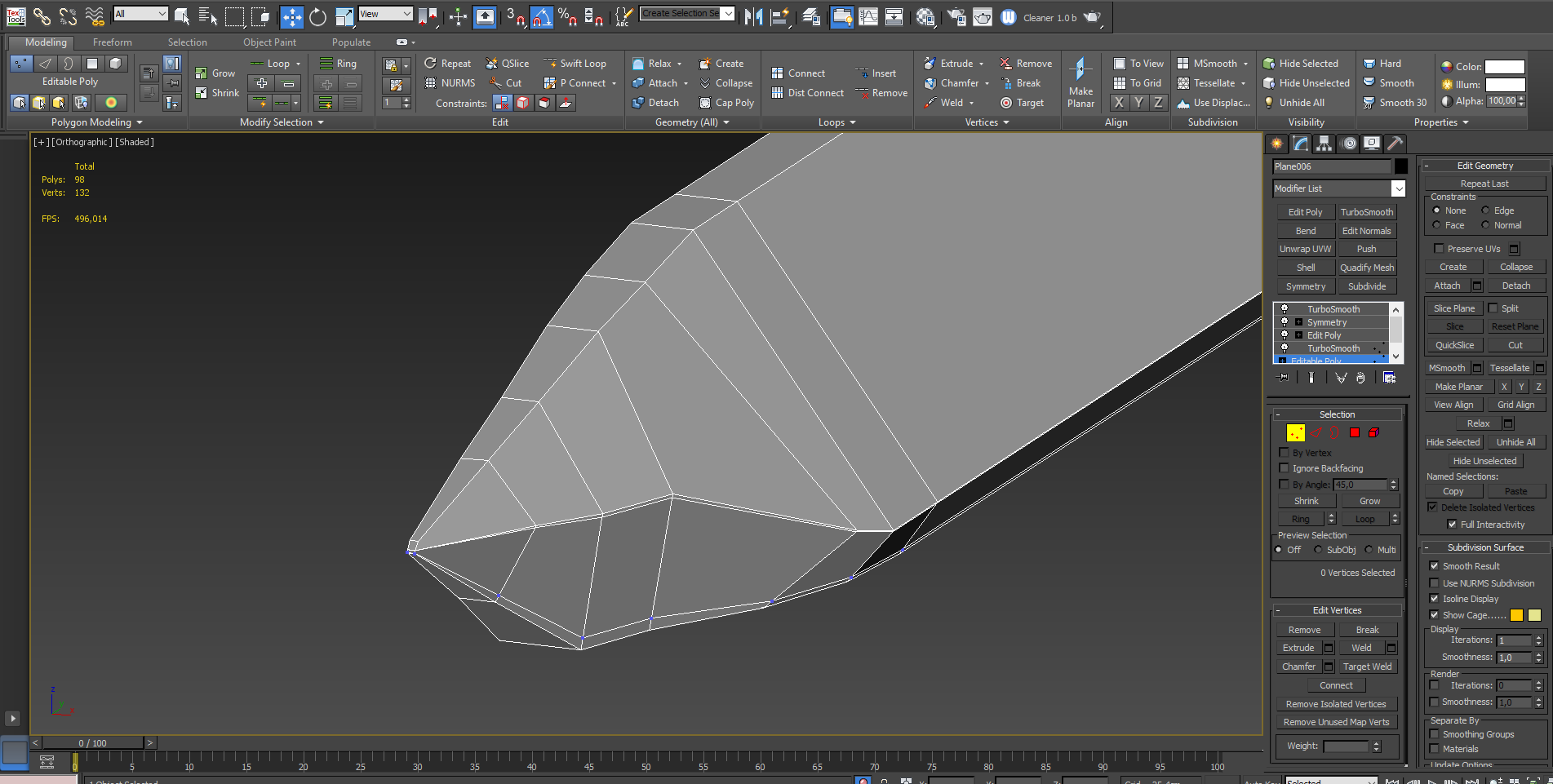
i tried to restart 3DS MAX but that didnt help
cursive sleet
ahh, i see :) thanks very much!
winter sparrow
what are unbinarized models?
grizzled halo
is there an order in which alpha faces should be sorted so the model from which they are part from is showed textured/not whitened out?
Ive tried a couple of sorting combinations but only one I managed to make it look ok, however I got a model that is much more complicated and makes it hard to sort through everything
 cedar coral
@TeTe thanks for sharing!
charred bolt
grizzled halo
is there an order in which alpha faces should be sorted so the model from which ...
Yes face order sorting is needed particularly on transparent textures, such as glass.
Start at the face which is going to be closest to the player and bring that to the top. In most vehicle cases, this only requires you to select the glass rvmat and bring faces to top. You'll need to do this often during development, or remember to do it right at the end, as face sorting will be lost along the way.
stuck oyster
Lot of overlapping transparency is not recommended as it can be a performance sink.
 junior ibex

Arma 3 | Official Website
9th Anniversary, Live Ops Status


Is there any particular obstacle that could be holding up the release of the LDPs?
stuck oyster
junior ibex
Is there any particular obstacle that could be holding up the release of the LDP...
There has been no new info
junior ibex
At this point it might wind up being easier to let people just rip non-premium content to modify
Cut/tweak that bit from A3's EULA about not extracting base game assets
quick terrace
junior ibex
~~At this point it might wind up being easier to let people just rip non-premium...
sorry what?
junior ibex
Rather than put together the LDP package, which is clearly taking a substantial amount of time and effort, modify the A3 EULA to allow the extraction of base game assets for modification and re-implementation
I am aware about the current status of rips, and I am not trying to endorse it unless BI would allow it specifically for A3's non-premium assets
I'm just spitballing ways that the community can play with those assets sooner
stuck oyster
junior ibex
Cut/tweak that bit from A3's EULA about not extracting base game assets
Bad idea.
bright echo
it's more likely a 'legal' thing to work through rather than 'find time in the day to zip it up and upload it'
stuck oyster
junior ibex
I'm just spitballing ways that the community can play with those assets sooner
In the meantime you can make your own stuff as practice.
junior ibex
I do
stuck oyster
Less talk about allowing ripping then.
junior ibex
Do I have to reclarify that bit?
stuck oyster
junior ibex
Do I have to reclarify that bit?
No, theres nothing further to discuss
We just have to wait until such time a release happens
grizzled halo
stuck oyster
Lot of overlapping transparency is not recommended as it can be a performance si...
i was considering that, i have some things that are usable and are supposed to be in front of the player lors of time and have alphas overlapping. If there a flag to avoid rendering them?
junior ibex
I know that, it's just it's been over 18 months now, and not one update
grizzled halo
charred bolt
Yes face order sorting is needed particularly on transparent textures, such as g...
thanks, yeah I figured out was was wrong with my sorting. I had read that you also needed to sort what was going to be visible after/before the glass. It looks like moving alpha haces to top and then the body in which they lay to the bottom actually makes them visible again, thanks!
junior ibex
stuck oyster
Bad idea.
Just curious since I'm clearly missing something here, why would it be?
grizzled halo
ripping is ripping no matter the context, a3 community is not fond of it, promotes stealing and garbage uploads. Even if the intention is good in order to create new stuff. As said above, its probably just a matter of legal intricacies that need to be hurdled over before allowing to legally use the base game assets. Probably something about lifetime and capital investments and what not but im not a legal advisor nor entity.
junior ibex
promotes stealing and garbage uploads.
Which is why I'm not suggesting it be allowed for anything but the base game files, but sincerely, thank you for the explanation
In the meantime
Am I missing anything?

Most of the fine details will probably get baked down, and I might go ahead and simplify some of the warhead geometry
junior ibex
Could the SAAMI missile be proxied into place for this? Or do I need to model a separate projectile for when the weapon is loaded?
