#WashTastic - 1W node based on E22-900M30S and promicro NRF52
1 messages · Page 7 of 1
but sometimes they have good deals
Hahaha do you ever not realize in design how tiny something is?

the holes for those pins might be a struggle on some printers, I gotta make them a little bigger too
I'll make a little test chunk people can print to get the fit right
All the time. Every time I design something to print… the zoom is too much at the app
Gonna have to start importing a model of a banana for scale
just made my order at jlcpcb
16€, way cheaper that the pogo pins
add the 4€ in the test spears, and maybe 1.5€ on 3d printing
Cheap
yeah and thats for 5 units xDD
You'll sell 2
😐
Just make enough for you, me, someone else and a spare
I don't think there's many people wanting to test 50x pro-micros.
Sadly.
I'll poke the local spanish comunity
the telegram group has grown massively
3200 memebers currently
holy shit
obviously there's a lot of inactive users, but the growth happened after the zero energy blackout that affected the whole country for a full day
80 dolla dolla
Promicro testing time

Well all five tested perfectly
However they behave sighly different from the other I already have
For example, the new ones do the reset when the .uf2 ask it. The olders dont; i have to manually double short rst to gnd each time.
The other different behaviour is the built in led when running Iris test firmware. The older boards blinks the built int led just the same as the gpios leds. This one doesnt. Is like it tries to breath when is ‘off’.
In any case all the test I ran with older and newer promicros were made with the same updated bootloader 0.9.2 from adafruit. I have the file located in a work folder and have used the same file in both old boards and new boards
Interesting
Look the built in led
Another characteristic is that these new boards have the bt antenna upside down
i was about to comment that the antenna looks different xd

Is the same antenna chip. The C3 antenna looks like that on the downside
Different chinesse cloner 😅


Old one. Unsoldered from a washtastic
Thats what happens when you try to separate them with slot screwdriver when is not yet hot enought
That’s awesome
Is this PCB avaible?

GitHub
PCBs i've made for meshtastic. Contribute to valzzu/meshtastic-pcbs development by creating an account on GitHub.
Thanks
Pretty neat
The version at my video is the old one with pogo pins
The one at the site is the new yet to be tested version
I ordered 2 days ago xD
Imma just use it for the nrf52840 so I dont have to Design a new board hahah
Tell me if it works
Well is the same but bigger holes to accomodate the test probe spears instead pogo pins
I dont really understand 😅
Oh so you Can just press it on
Nice
Btw the promicro is yanked from here: https://github.com/ICantMakeThings/Nicenano-NRF52-Supermini-PlatformIO-Support

GitHub
Add NICENANO / NRF52 SUPERMINI to PlatformIO. Contribute to ICantMakeThings/Nicenano-NRF52-Supermini-PlatformIO-Support development by creating an account on GitHub.
I dont really know what you mean
I understood from here that you wanted a model for a new pcb?
I meant I use the pro Micro to Test stuff for my nrf52840 SMD node
Ohhh right
My V2 should arrive soon
What v2?
Sorry missing context, my node v2.0
The better Version of the First one
Testing boards are shipped, estimated arrival 30.9
Cool. Mine are packaged, I guedd they are about to get shipped
Ooh you guys will probably get the parts sooner than me, I'll upload the case source in a bit, it might need some adjustments for the probes
Test fit parts to check the probe hole sizing (might need to be drilled afterwards tbh, depends on your printer)
and the enclosure itself:
u gonna publish these on printables or something? so i can link an give credit to u?
or do u have github account?
I can yeah, I'll wait til we make sure it actually fits 😅
https://www.printables.com/@DarkStar851_1890652
Sounds good
Not sure but i think elecrow is also getting the jig 🤣🤣
Atleast i understood something like that
Oh yeah how is that going? Did you reach then wirh your tests results?
I will try it once i get everything on my desk
I did email them about what i found and today my contact on discord messaged and asked if i got the boards and if I managed to test em
Said the same thing that i emailed
Lol
But then also we just talked bit and i forwarded some of ur videos xd
Of working aand broken board xd
Yeah those two are fun
at least elecrow knows how to make actual professional test probes 😂
The day I received the freshly test board from jlc the first board I try is the one with the fliped gpio. I had to look twice the led to be sure the polarity wasnt reversed
picturing someone in their fab trying to assemble this thing

Yea 🤣 no assembly instructions nr pics of finished unit lol
Are they building a jig?
I understood its what i made lol

Are they building your jig? Lol
I assume so
I’m looking this at my junky cad app, looks awesome. Did you modeled the probes?
Looks good 🤣

Yeah haha, the pin headers I just got off grabcad, they're slightly wrong
they're not 100mil they're 2.5mm lol, but close enough, the holes are from the pcb dxf so they're in the right spot
I guess my appearances don't translate properly in step, in fusion they're even the right color lol

Oh Shapr gets them right too, just that web app I guess
Mine are still gonna be a while, probably next month 😭
Oof
Oh, or not, "arrived at local airport"
🤣
that usually means ~1wk away
I figured for $5 with free shipping they'd glue them to a postcard
Mines still in china i think
Estimated delivery October 8
So ye
Well see
Usually gets here faster
Then i can start testing the 50 promicros in got lol
I only have 5 to test right away 😅 but I liked the tester board and it looked easy to make a case for
1 promicro per pcb lol
I expect to kill a few pins in test fitting so, parts to assemble 4 lol
😴 ttyl, keep us posted if elecrow actually tries to make one of these lmao
I realized too, you could put a solder a programmed promicro to the pin header side, and use it to function test washtastic boards before soldering
case would need a few tweaks but nothing hard if that'd be useful
Oh yea true 😅
Tho the promicro would not be on female headers.xd
So far i haven't seen a non functional pcb
Only promicros
But u never know lol
Anyway now I'll go for real 🤣
I had four to test, the first one was the bad one
Next batch came yesterday, 5 pro micros, all 5 tested good
See and that's just my luck too lol, at least I'll have peace of mind


My test pins are in china but my boards are in Finland and karman has it the other way 🤣🤣🤣
That is hilarious
Gonna get my boards today
#1194757507013427250 message @olive basin dunno if you saw this in the other channel, case fits 🥳
Guess you'll have to wait on the pins though 😭 damn typhoons
For him but does it for me 🙃
I mean he printed in ASA, basically a torture test for the holes 😂 if that worked you should be fine
her printer (ender 3?) has been making huge blobs lately
bowden system + wet filament, bad combo
Oh oof, well it should print fine on like any current generation cheap printer if you know anyone
I have ender 3s, but the newest one 😂 they don't even look like enders anymore

QQ2
QQQQ
Guess what's waiting me at home? 🙃
a printer?
I wish 😅
well, technically at home there's a printer waiting
Ahahah true lol
I don't think thats the correct size 🤣

nah, they are
this picture doesnt really show how small they are
in fact, they fit in the holes of the promicros
i mean the screw hole
at least in the 3 lined pad
ahh
yeah that hole is not even similar to the one on the 3dpiece

i dont mean the location, I mean the size
yea yea
ah nvm 🤣
not jlc issue lol
ur board is gonna be correct
i wonder how bad it would be if i just drill a hole 🤣
whats the issue ?
preview of my board look fine
why yours is that small ?
also, misplaced
well, you have the traces map
you're the one to say if you can drill
i have 5 boards anyway lol
they arent even mounting holes lol
i had orderd a one edit older what u did 😅

nothing routed there, drill away should be fine

holy shit it looks like I made it
ill have to record them a video how i test the boards
aparently they are still getting the error
well now i have brand new promicros xd
i can test with those lol

Try uploading the Meshtastic fw to a loose one, and put it on the test bed.
Have you changed literally anything on your PCB between JLC and elecrow?
nope
😵💫
You got an Elecrow without a pro-micro on it?
Ill be free around 12 noon UK time.
We can go through what is what then.
Need to get to the bottom of this.
🧐
agreed
i rly dont wanna switch fully to v4.0 cuz its expensive as hell
tho that would rule out everything 🤣 most likely
Can you download the Gerber files you sent to each of Elecrow and JLC, plz?
ill see if i can
but the fact that i had jlc boards fail now is interesting
so 5 total now
5/10
yea i got the files
My current meeting is interminable... And I asked a question, so I'll be a while.
Alr
have to go out
I just read everything...
in the meantime you should recover a elecrow board by desoldering the promicro and soldering a female header
to ease testing
at this point I don't know how to proceed without a logic analyzer
try testing continuity and shorts between pins and also power it from a bench power supply, 4v 2A to the battery port to discard usb underpower
will see ytou later
will try 🤣
2 mins - just grabbing a sandwich.

@severe halo @heady mulch
This is the elecrow promicro
Now I'm doubting myself on pcb design
i think ill get the printer later, ill buy an oscilloscope 😅
also logic analyzer would be nice too
if you just need like low speed bus pirate level functionality, https://github.com/dotcypress/ula

GitHub
μLA: Micro Logic Analyzer for RP2040. Contribute to dotcypress/ula development by creating an account on GitHub.
rp2040 absolutely slaps, so much cool stuff they can do
if it can capture spi etc we gud xd
It says it'll do 100 MHz sampling so, it should
something doesnt feel right here
I get that LEDs blinks all at the same time
but it did cost me viewing the video like 5 times
BAT and VCC are perfectly visible, the GPIOs ones seems too dim for my eye
to me all leds are equally powered
after i flashed the meshtastic generic bootloader they became dim
with the factory bootloader they were bright
so could it be the bootloader?
gpio should be 3v
use a multimeter, see how much voltage do you get on gpio when 'lit'
i'm gonna have to do that tomorrow tho 😅
if its too dim, like 1.5v or 1v... then it could be that radio is not getting ones and zeroes
but yea the once i bought were bright untill i updated the firmware
I dont know if bootloader has something to do. In any case, flashing the adafruit version is free
will try doing that too
please, before flashing, first measure the voltage level
I'm really curious about that
GitHub
24 channel, 100Msps logic analyzer hardware and software - gusmanb/logicanalyzer
too professional, needs to be made from random parts you have in your drawers
oo, I didn't know it could run standalone on just a pico, I thought it needed the other stuff
sweet then
haha no its just pico too
Yeah just reading here now, that's awesome
tho it prob would make it better with the pcb xd
dammm... aparently u can chain these to get 120 channels 🤣
yeah some people really cooked with these boards 😅
the PIO can do stuff that's like, impossible on other mcus, it's basically a really really shitty fpga
as long as whatever you're analyzing can be transmitted over random lengths of wire I don't think no pcb will be a problem haha
yea xd
Very cool for stacking them though
Try flashing back to the nicenano bootloader
yea
It could be some default option on fuses on your programmer
🤔
Im not sure because I dont know the nrf52840
Unsure which option would cause this
But being a different bootloader burning method than uf2 it could be it changed sonething in addition of the bootlader sector
Does the blinky sketch enable the 3v3 pin?
every pin
No, I mean there's pi 0.13 that controls the ldo
Aw fuck. Now that you mention that ai just found this

Is missing in this video too 😓
Gonna find that board

Definetly fell at some point

Im prettu sure it wasnt me
it could have come like that rly
I took this picture just after opening the bags
I made sure Inside the bags there were only pins
BUT that board tested fine
it most likely was the battery charger
Chinesee doing chinesee things
if u plug usb in on this one and another one what is the difference
Btw these 4 pads are for the voltage divider to measure battery. Found that looking for the promicro schematic

hmmmm
Those fuckers put the voltaje divider there, just saving the resistors
what pin does it go?
P0.04 if they just copied nrfmicro (which it looks like they did) https://github.com/joric/nrfmicro
GitHub
A Pro Micro alternative for wireless keyboards. Contribute to joric/nrfmicro development by creating an account on GitHub.
This

Dead unused gpio
my eyes
Thats the best I can do
0.04 is one of the analog inputs, the default diy promicro firmware uses it as well for vdiv
promicro variant uses pin 0.31
I dont find anymore references to tag 004
why didnt they just fill it 😅 would not have costed much lol


And 0.31 would be free
damn I don't think I have anything the right value that size

indeed
2:3 iirc or was it 3:2 🤣
yeah idk if I have anything in the high kohm/megohm range though in 0603
closest I've got is 470k/680k, slightly wrong ratio, but they'll fit lol
i mean u can just adjust the adc overide to adjust it
oh. no they won't 🫠 those are not 0603
they are on the original pcb layout, on this they're 0201
haha
not that hard to do with a hotplate though
one good thing about 0201, they're soooooo cheap

resistors are cheap xd
tiny I guess
I mean yeah but even compared to other resistors they're like extra cheap
I guess less ceramic, doesn't cost as much
gotta wonder if they're getting close to just what it costs to put something tape lol
🤷♀️
but yeah the pads got pasted so just throw some paste flux on, verrrrrrry carefully position them, reflow the board
hah ayea
Hardly worth the effort but if someone needed the extra analog input for something 😛
😅
Would been easier if those freaks used the pick and place to place this damn resistors..
😅
indeed
its not too expensive to get 5 assembled 🤣 but tbh 2 prob would be enough lol

i had to convert the pcbway bom to jlc 🤣


🤣
i tought the difference would be bigger xd
😭 it's like 4 parts you do not need assembly
5 I guess
*6/7
Yea i know xd
Tbh I've never ordered assembly before, the last time I was messing with electronics OSHpark was still dominant lol, very much the "solder it yourself dummy" era
group buy? wouldnt mind to have one
Basically a smd practice board
I mean i wouldn't mind
could edit the footprint, it's kicad so not too hard https://github.com/gusmanb/logicanalyzer/tree/master/Electronics/LogicAnalyzer/LogicAnalyzerV2/designs/jitx-design/kicad
GitHub
24 channel, 100Msps logic analyzer hardware and software - gusmanb/logicanalyzer
0402 is doable by hand though
Didn't search good enough lol
Indeed
I wouldn't want to do a lot of them, but with that much space around them on the board it's not bad
Hotplate 🙃
I love how they did impedance matching on the level shifter lines 😂
It certainly doesn't hurt, but 100 MHz
and like they're just routed however rpi foundation felt like that day anyway once they hit the pico
Can do 400
Tho source ur own pico 🤣
100 seems a lot to me
I remember when I studied electronics, our osciloscopes were still tube ones, and they did max 20 Mhz
I'll have to check tomorrow what lcsc quotes on the components including shipping
kids nowadays are too spoiled
Haha
the scope you learned on can be outpaced by like 10 cent microcontrollers now though 💀
Ahahhaha
definetly
our bench computers were PIII 700Mhz at most
my watch has more cpu, ram and disk than those
it's crazy how cheap some of the really basic scuffed mcus are, I don't envy anyone writing firmware for them, but literally 10 cents on tape
Yeaa
When I was last into things, atmega arduino clones were like very hit or miss if they'd even work, now it's like "here's wifi and bluetooth oh and it runs on batteries, that'll be $3"
Haha
atmega werent known when I started..PICs were the kings
used to get free paid tv
xD
I remember the pic, they were still around when I started, though losing relevance
remember that microchip (makers of pics) bought atmel.. xD
damn I never saw that, at least they kept making atmel's stuff
pics were the kings for everything, is just that atmel was lucky to be choosen by arduino
I think it was because the atmega could do serial dfu and pics needed a pickit
what boosted atmel was the ease at programming from both thearduino IDE and the bootlader, wereas to do something at a PIC you needed special microship IDE,a lot of asm and a special hardware programmer
oh yeah hadn't thought about the programming environment around it too, I've never coded for a pic
I used to have a pickit, long long ago

that was modern lol
oh actually yeah that one's newer, I think I had a 2? was around like 2007-08
this is the one I had

lol omg
I also had cheapo RS232 programmers lkike this one

long gone are those days... now microconcrollers have embebed usb and lof of fancy stuff
microchip wasnt interested in the hobbyist market but learnt the hardway from atmel that, if hobbyist doesnt make money directly, you just need a little of them working on real things to suggest to use an atmel that they knew from they hobby on real production environment, ordering thousands of them
so microchip had to buy atmel 10 years ago xDDD
Not to mention cornering the hobby market gets you a ton of exposure in education, I'm sure a lot of people learned on Atmel 😅
yeah, pretty much like rpis
they were originally a design to supply cheap $30 computers to education...
then you see lots of massive projects made with them
Yeah and built into everything, why design your own sbc when you can use a $30 education board
oh crap they ran out of them
inflation 💸
Guess what voltage it was 🙃
3
1.8
Close but no
1.5
its the god dam bootloader
hey @spiral panther the generic booloader seems to do something weird.
its making the pins output about 1.6V rather than 3.3V
Looks way better now
This is with the generic bootloader
vola

Oh ok, it seems that board have a specific 3V3 setting here - https://github.com/adafruit/Adafruit_nRF52_Bootloader/blob/6a9a6a3e6d0f86918e9286188426a279976645bd/src/boards/nice_nano/board.h#L30C19-L30C49
which wont be in the generic bootloader, but could at some stage see if adding it wount effect any board
yes, i only see it now. not this issue myself either yet

GitHub
A Pro Micro alternative for wireless keyboards. Contribute to joric/nrfmicro development by creating an account on GitHub.
but i recall some metnion of it before with the PCA10059 dongle that could get stuck in 1.8v mode


GitHub
After flashing the bootloader to the "Dongle", the dongle's on-chip LDO regulator gets to the mode where he outputs 1.8Volts instead of the standard (when you buy it) of 3.3Volts. Thi...
hmmmm
with that donlge you had to cut some traces to use external 3v3
so something has happened between my promicro batches 🤔
oh
well here another mention of issues when is below 3.0v
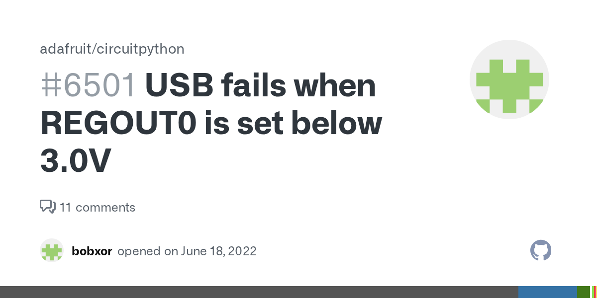
GitHub
I've utilized the nRF52840 Dongle (PCA10059) with nRF52 SDK (Segger) projects to use USB while regulating GPIO voltages at 1.8V. I'd love to use CircuitPython for an educational target, but...
awesome 😅
and im sure i came accross a command that can erase that section i think at some stage
say you set it wrong for example
yeaaa
yes, i for example used openocd to read a nrf52 for backup
two flash banks exist
flash banks
#0 : nrf52.flash (nrf5) at 0x00000000, size 0x00000000, buswidth 1, chipwidth 1
#1 : nrf52.uicr (nrf5) at 0x10001000, size 0x00000000, buswidth 1, chipwidth 1
nrf52.uicr
4096 bytes only contain these registers
hmmm
so you could compare
and you can write that uicr section back also
flash write_bank 1 flash-bank1.bin
i only have esp32 nrf52 swd programmer 😅
it can dumb flash
1KB file
so idk if its correct size
there we go

so, mistery solved ? elecrow was instructed to flash the meshtastic bootloader?
sorry, been all day out in office event at nature
I mean, in the original deployment, I was asking if you instructed electro to use meshtastic bootloader
before all this
ah yes
the generic bootloaders were created long before it was known how board design power pins were used, either now add it to the bootloader or use nrfprog to fix
This would have been hard to find without a nice promicro tester! Get yours now!
Well i would have found that after i got my oscilloscope xd
i cant import this to fusion for some reason, the fusion file


doesn't give an error? :S
no clear error either
wtf?


yeaaa
Give this a try, downloaded it from Fusion Hub
i know 😅 tho the button was in the way lol.
fusion did accept the step file and i could remove the button so we good
oh, right-click in the slicer and split to objects
😅 sorry I forget sometimes people don't use my workflow
I always export the whole thing as a step then split and arrange the parts
i dont need to separate stuff usually so i dont remember
I like doing it this way so if all someone has is the step file in the future you can still see how everything goes together, not really important here but for bigger designs haha
makes sense
https://oe.ink/l/Fh49pi19Ym
lets see how this goes
OctoEverywhere
Beautiful webcam streaming, real-time AI failure detection stats, print progression, streaming stats, and much more.
printer go brr
oh god that's still bowden extruder
at least you didn't die on the glass bed hill
hahahah
this was my first printer 😅
paid like 200€ few years ago
will be getting a new one eventually
well doesent run stock old crap firmware anymore tho xd
oh ye alol
klipper go brr
I never knew the pain of marlin 🙏 these v3 corexz printers were my first
I do wish I had something enclosed though for asa
awful
indeed
sounds like a good way to burn out the flash on your control board lol
hahaha

hotend is still stock 😅
i think thats limiting my petg speeds most likely
Yeah it could for sure, petg likes a long melt zone
Try rapid petg from elegoo, I bet it'd run good at like, the speeds you're used to lol
It's really cheap over here too, usually the same price/close as the cheapest regular petg on amazon

😅

addjldsksdj
takes me almost 2 hours
pla
i could prob go faster but then i run into every limit 🤣
If the printer can't launch itself off the table, are you even printing?
also the belts are starting to show their age xd
I have a brand new belt for the corexz assembly on mine, in case it ever dies, but I REALLY hope it doesn't
it's threaded around like 20 different pulleys
creality: "hey everyone likes corexy, let's just turn one sideways and tell people it's good"
😩 I guess it does have some advantages, Z movements are realllly precise, and fast
it's so fast moving in Z, to home, it just sends the gantry all the way to the top and back down lol
hahahahaha
It's good for printing really low layer height stuff, hueforges especially
https://all3dp.com/2/anycubic-mega-zero-upgrades-mods/ this does have direct extruder upgared 😅

All3DP
The Anycubic Mega Zero and Mega Zero 2.0 are easy printers to improve. Read on for some of the best Anycubic Mega Zero upgrades available!
and some others
hahahaha

the amount of weight that adds to the top of the toolhead would probably add so much vibration you wouldn't realize speed gains
yeaaaa
xd
i think the best would be to upgrade the hotend
but idk
i guess if im rly bored i could just try pushing this printer as far as it goes 🤣
petg is no go but pla
Just make sure you're not getting to a point where it'd be cheaper/worth it to just buy a new one 😅
Seen quite a few riced out ender 3s that should've just been retired
I mean I'm all for running them until they won't go no mo as secondary/slower printers
i mean in terms of what this can give as is
i will buy a new printer thats for sure xd
Hotend's cheap at least, I think triangle lab makes some nice ones on aliexpress, idk if they have 'em for old anycubic models though
they have all the old creality ones covered
you'd need to change your probe mount to be lower but I think that bolts onto the stock toolhead
the last one yes that is for mega zero 2 but thats the stock one xd
oh, yeah oof that heat block is tiny
I just assumed it was like their volcano hotend but no :((
yeah fair that sounds like a hassle

none of those kingroon sellers ship here 😭
This just finished with JAYO PETG, I couldn't find "alley cat remix made of random garbage" so I made my own 😭

I might redo it with the pwrd logo filled in white
Whats wrong with it? Looks fine to me
The crimes are inside, the case actually turned out nice I think

my faketec boards were inbound when the mail strike happened 😭
Yeah that's no fun... I have a feeling its gonna be a while too... I actually forget how long the last one was
Nearly 2 months 💀 and two of my parcels just got entirely lost
oooof
Honestly, I only use snail mail for bills, just so I can shove them in my closet for 10 years 😂
I don't even do that, PDF everything pls
I'd be fine though with once a week mail delivery, who the hell needs letter mail daily (other than some businesses maybe, but everyone??)
I think it's funny that they say they're broke, yet they get paid to put flyers in people's mailboxes
I guess the flyer game isn't as profitable anymore either, e-flyers
All the unsolicited mail we get is either "oh it's the weekly <store that always does it> flyer" or "wtf is this and why was it sent to me"
My neighbour across the hall still gets the newspaper every day, but she's gotta be like 70 or 80, so no computer literacy
we don't even have a newspaper here anymore, RIP The Telegram
I was looking for one a few weeks ago to use for cleaning windows, but nada 😭
The only time I really want flyers is for packing material 😂
I have a giant roll of craft paper for that but it's a bit too thick for window cleaning 😂
i got 4 in stock again 😅
https://www.etsy.com/fi-en/listing/4323773321/washtastic-nrf52-powered-and-solar-ready
This is just when I swaped my 3 old month geeetech for prusa mk3s
yay, at least the board lines up right
Also had to do some sand paper action 😅


Stupid grabcad, the pin header model I was using was wrong, I noticed it a while ago but I thought it was close enough
I'll make those slots longer on the ends
The model I had, instead of actually doing 100 mil pitch, they're 0.2mm pitch
which .. isn't a thing
so they're just too short
hey you can kinda see where the holes are!
also the board is kinda press fit 😅 doesent come out if i shake it
0.1mm tolerance might've been a little close heh, that's alright, I'll make notes and adjust it later
for my printer 🤣
👌

You should for every new roll you use, it's worth it if you need to print tiny holes
or just be accurate much at all
you don't set flow ratio in klipper 🤔 you mean extruder distance?
that shouldn't change
flow ratio is a setting in the slicer, in your filament settings
maybe i did change that
some of the fancy new printers just do it automatically (to make me jealous)
......

2mm is fine, you don't really need them to be snug in there, it's just so you can't bend them enough to break them
plus that'll account for any misalignment from (I assume) hand drilling


ohh right
screw holes in the print are fine
woah really? I thought they'd be too tiny
nope
anxiously awaits pin test

wait until I have my boards
dont take Iris printer as a standard...
you need thinner drill bits..
we just got a civil protection emergency broadcast on all phones about new storming hitting east spain tomorrow
11 months have passed since the famous valencia flooding
schools are not opening
so people cant go work either
I mean isn't that good?
nope... schools closing should be good, but work places and offices are not closing
so, what do I do with my kids ?
who's taking care of them? best cases are to work from home (which I usually can do)
But most can't
but tomorrow I have to attend a venue as an IT support technician
Oof
the venue is not yet to be closed due to weather soo... who knows what's going to happen
chaos in any case
Ur not the only one most likely
yikes, stay safe, if it's anything like the typhoon that hit asia uhh hope you have a boat
Had to make it smaller 😅

haha
Elecrow was able to get the boards to talk with the lora module
so question, what are the advantages of a 1W? or lower W? i saw someone promoting a 2W as well.
1W/30dBm is higher output power (more than legal in some places -- it's the limit for the US, but e.g. EU_868 isn't supposed to go above 0.5W/27dBm. most radios you can buy are 0.15W/22dBm max. it won't always help you but it can get a bit more transmit range and a bit more receive sensitivity
One thing about this is u could possibly have a longer coax run
And the u could compensate for the loss by increasing tx power
Yea we in eu arent supposed to go above 500mE erp


Which one is which?
yellow is battery
Why do they do that?
i mean they can test if stuff work
And you pay them to do that?
and im selling my boards through them so i wanted them to make sure that customers get working boards
nope
Oh so they Test the modules before selling


in the pcb section theres a preconfigured tag with the order number
I though that was horrible
so I went to deactivate it, and found you can put a small string (6 char long max) and a numbre from i to j
from 1 to 5 for example
if you make a second batch you can put 6 to 10
in any case the position has to be random if you want to produce the boards as quick as possible and dont want to talk with them
oh coool


yup
the only board with order number I have from jlc is the first one, the 30x promicros xD
every board in that sense is unique
everything else I stoped and took my time for every option trying to understand their meanings and how would affect the order and if I need it
yeah, helps to identify them, and batches
yea
btw the pcb fits reeealy thight
I dont even need the screws
Is a really cool gadget, pretty happy with the final result, really really cool. Nice board design and nice case design. Good work everyone!
to me at least haha
in the sense that u dont need to desolder a promicro when it doesent work
for sure this ads extra steps but its worth it
@olive basin for V3.1 of the washtastic board which resistors did you use? 330k and 1M? trying to get the ADC right https://github.com/valzzu/meshtastic-pcbs/blob/main/WashTastic/pics/Schematic_1W-meshtastic-node.png

GitHub
PCBs i've made for meshtastic. Contribute to valzzu/meshtastic-pcbs development by creating an account on GitHub.
It's 2x 330k on top of a 1M resistor
thats what i thought thanks
It's the same as the standard promicro firmware
ill just go find that number in the meshtastic github repo then thanks

I think it's 1.73, which is 1.66 plus a bit for luck
yeah thats what it looks like

GitHub
The official firmware for Meshtastic, an open-source, off-grid mesh communication system. - meshtastic/firmware
And based on ((R1+r2)/R1)-1
perf thats what i was looking for thanks a ton
None of the pins are straight 🤣

My advice is Next time solder them straight
Just 3d printed my node

So i Can Test my cases befor the PCB arrives

You bought spare PCBs as well, didn't you?
Remember when I said you should solder 2 in a stack?
Or just a bit of perf board to stabilise them.
I mean i have 4 not used xd
Just use a bit of proto board.
Pretend you're @minor shoal
They know how to make do with scraps 😉
also didnt help that mu printer didnt make the holes the correct size
that would have helped too
This seems more expensive than having a real one
I cant wait for the PCB
I have to Test my case
or having drilled the holes with the proper bit
didnt have smaller one
I mean, there were a lot of things that could went wrong that went wrong haha
toms idea is good, just stack two of them
with some separation
puting something between them like cut protoboards to ensure both are properly parallel
It's not my idea, btw

toms stolen idea is gut
I'm just good at remembering known solutions to problems
i mean yea but there isnt room in that 3d print
and the idea was that the print did it
but my printer bad
they? I am big, but not that big :D
reminds me of the joke about the scale that shows the message "one by one, please".
Reddit
Explore this post and more from the 3Dprinting community
Hmmm
I was drying at 60c 🤔
pla should dry not more than 60C
any bit more will melt the full spool
the post is about petg
petg will dry at 60C it's just ass slow, my dryer goes up to about 55C and it takes a full day to get a noticeable difference 😭
I love the Polymaker approach to drying but I wish it was both more power and less loud
Give me a 120mm Noctua pushing 200W of dryer power on max
But how would you know it's on?
Funny you say that, I wanted to buy an electric motorcycle, but the only ones they sell are crotch rocket style... so I actually thought of buying a hog with saddle bags and granny bars and electrify it so I don't have to lean over all the time 😂
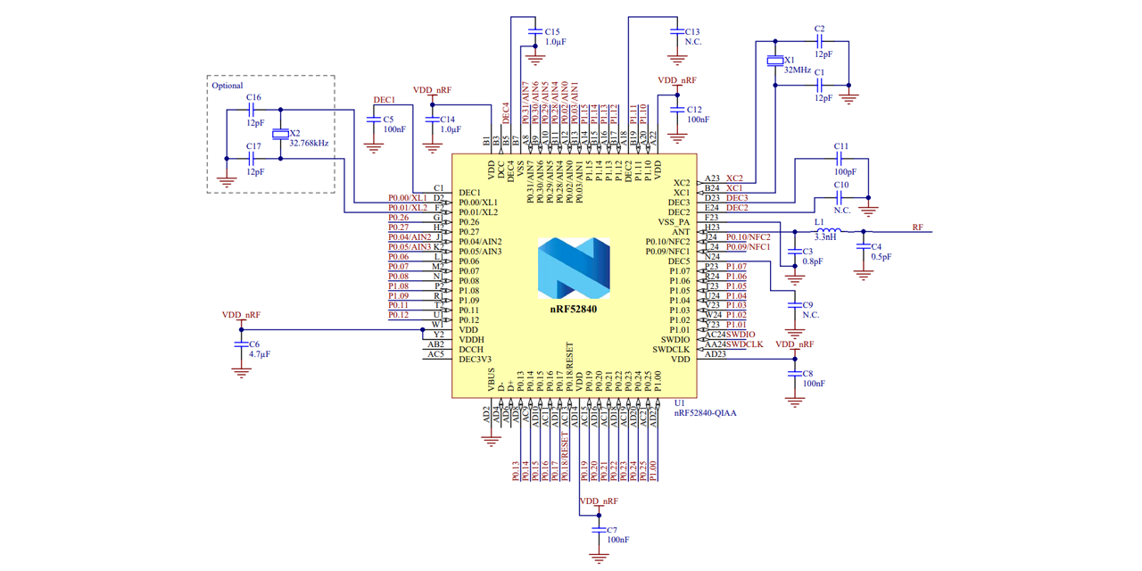
@heady mulch sorry to bother you here.. I found this schematic and was wondering about the ht-ra62/ra-01sh connections. Is it right to leave rxen and txen unconnected?

Yes, switching is internal.
Right, I found this in the ra-01sh schematic

Didnt knew those two were internally connected to dio2
Cant find a ht-ra62 schematic but is supposed to be the same, right?
Never mind, it wasnt in the datasheet but is as a separe file. Same implementation..
So then, why is it necesary to connect rx_en to promicro 017?
For the RA-* boards, it isn't
for the E22 boards, maybe.
For the WIO sx1262, it is required
For the e22 it is for sure required. I remember testing promicros in wastashtic boards without conecting 017 and they didnt work. I didnt knew that those were internally conected on ht-ra62/ra-01sh boards. Thanks!
I rly do need to get e22p modules
are you 915 or 868
868
Haha
this needs the E22P-XXXM30S :p
Oh yeaaaa.... True
New month so it's time to ask if Washtastic is generally available anywhere
haha
I hope the Elecrow thing works out, that'd be great
yeaa

Perfect gif 😉
It hurts.
China had their national holiday so yea
if you order aliexpress right before new years they auto cancel your whole order and you get a $2 coupon for every item they cancel
ask me how i know
lmao
i had 60 coupons
except one per order and they wouldnt combine it
Lol
monsters
#thatsthefeature
Works if you order right before a mail strike too, and they don't cancel so it still shows up eventually lol. Harder to time though.
Elecrow apparently is ready to ship WashTastics
Is this chart still accurate? IIRC there was a PR around to make Meshtastic PA-aware

well..... if u use promicro firmware yes then its correct
but if u use the washtastic firmware then its not
washtastic variant is already in the main line code, just not compiled, but you can compile it by yourself
ye
As Iris noted, the TX power table is only valid if using the nRF52 Promicro diy firmware. If using washtastic firmware then the configured value is the output value
somebody fucking bought 5 washtastics
i just saw the email and i was like what the fuck 😅
idk
what am i supposed to feel 😅
i know ppl have been asking for these but holy shit
think you got to pay half osciloscope
That was my group
We wanted four and then were like "Eh, fifth one means they're all cheaper, let's goooo"
hahahaha
FWIW, I think their description could use more details. It's not clear that it has MPPT unless you're staring at the board and recognize the dip switch layout or know what a CN3791 is
I'm surprised they're not recommending solar panels with them, too
thats my descriptionm 😅
Ah. Well, I could put together some editing/proofing feedback if it's welcomed, and if it's not, that's okay too
i just noticed a typo
everything is welcome 😅
im not the best at writing
and i think i did use AI too bit xd

i dont think thats correct 🤣
CN3791?
ye xd
Hi, mystery customer here 👋
Fixes:
- Update charger module to correct identifier
- "Watt" is not capitalized when spelled out, only when used as a symbol:
1Wvs1 watt. - Hyphens (
-) between the number and the unit (1-watt) are only called for if they're used before a noun that they're modifying, so "maximum output power of 1-Watt" should lose its hyphen and capitalization. - "low power operation" should have a hyphen: "low-power operation"
- In paragraph two, consider expanding "nRF52 MCU" to "nRF52840 MCU".
- It's not clear from just the listing that the board supports MPPT.
- No part of the listing specifies that it's a LoRa radio unless you already know that Meshtastic uses LoRa.
- The frequency isn't explicitly listed unless you already know that the
900Min the Ebyte module name specifies its frequency.
Suggestions:
- It would be great to have side views of the board that show ports and buttons.
- The dimensions of the board, mounting holes, buttons, and ports aren't displayed or linked anywhere. "PCB files are on GitHub"
- The title says "Solar-ready", but the description feels like it could use a line like "Ideal for solar-powered mesh radio nodes running Meshtastic, MeshCore, Reticulum, and other 900MHz mesh radio projects."
- A lot of information in the listing is contained in the annotated diagram of the PCB. This should all be in text that is searchable so someone can quickly discover that it has multiple I2C interfaces, buttons, a power switch, antenna port, etc. This should help the board get found by prospective buyers, as well as help people have a positive experience when ordering it.
- A table that lists out (and links to Elecrow's pages for?) each of the connectors the board uses: QWIIC, battery, solar
- If it's appropriate to throw the Meshtastic logo in here somewhere, I would.
- Mention what features we get out of the boards you're namedropping. Ex: Does the XB8089D0 give thermal cutoff?
- The Promicro board usually has a maximum charge current of 100mA IIRC, so it may be good to specifically call out this board's max charge current/wattage
Have you considered making ones with other Ebyte modules available? I'm thinking the 2W one or a 400MHz one
400MHz should work if it has the same pins and uses 5V for power
2W maybe works but not sure if the boost converter can supply enough current
I hope the rest of that is comprehensible for someone who doesn't live in my head
WashTastic Mesh Radio Node - Solar-Ready LoRa Solution
The WashTastic mesh radio node is designed for Meshtastic, a LoRa-based mesh networking platform, but adapts seamlessly to other 900 MHz (868MHz) mesh radio projects like MeshCore and Reticulum. It combines a powerful 1-watt E22-900M30S LoRa radio module with an nRF52840 MCU for efficient, low-power operation, making it ideal for off-grid and solar-powered applications.
Key Features

LoRa Radio Module: The E22-900M30S operates at 900 MHz (868MHz) with a maximum power output of 1 watt, offering extended range for reliable communication in challenging environments. Note: This power level exceeds legal limits in some regions, such as Europe. Always check and comply with local regulations.
Low-Power MCU: The nRF52840 microcontroller ensures ultra-low-power operation, perfect for energy-constrained, off-grid projects.
Solar and Battery Management: Equipped with a CN3791-based charger supporting Maximum Power Point Tracking (MPPT) for efficient charging from solar panels or any 5-28V power source. The XB8089D chip provides battery protection, including overcharge, over-discharge, and thermal cutoff for safe, long-term operation.
Maximum Charge Current: Supports up to 2A charging current, significantly higher than the 100mA typical, max 300mA, of ProMicro boards, enabling faster and more efficient battery charging.
Interfaces and Connectivity: Includes multiple I2C interfaces (via QWIIC connectors), a U.FL antenna port, user-programmable button, and a power switch for versatile control and integration.
Compact Design: Measures 50mmx70mm with strategically placed mounting holes for easy installation.

Build Your Own
The WashTastic is open-source, with PCB design files freely available on GitHub. Order your board through services like Elecrow and customize it for your project.
Connector Compatibility


Connector Type,Description,Compatible With
QWIIC,I2C interface for sensors and peripherals,"SparkFun QWIIC, STEMMA QT"
Battery,2-pin JST-PH for LiPo batteries,Standard 3.7V LiPo batteries
Solar Input,2-pin JST-PH for solar panels,5-28V solar panels or power sources


Solar-Ready: Optimized for solar-powered mesh radio nodes with MPPT for maximum energy efficiency.
Versatile Applications: Supports Meshtastic, MeshCore, Reticulum, and custom 900 MHz (868MHz) LoRa projects.
User-Friendly Design: Features a power switch, programmable buttons, and a U.FL antenna port for easy setup and operation.
Open-Source: Freely available design files empower you to modify and build your own nodes.
just threw the old description to grok and what u suggested and it gave me this.
ofc nothing perfect
It looks better to me, plus or minus some formatting and sane spacing
I didn't notice that Elecrow says they don't include import taxes in the costs. I'm very curious to see how that works out
looks better in grok chat xd
Sometimes if you copy it out into something like Marktext or Obsidian, it'll retain the formatting and then paste nicely elsewhere
only 20 available?
-# cash flow
I manufactured 20 and 15 is sold according to elecrows site
I mentioned it on PugetMesh yesterday and someone was disappointed they were already sold out 🙂


thats 20 boards on jlc
tho in this version bme280 is now aht20

this is with it shipped to me

and this is elecrow
without shipping and tax etc
Give them a kick.