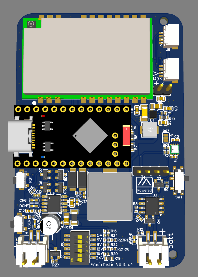
#WashTastic - 1W node based on E22-900M30S and promicro NRF52
1 messages · Page 4 of 1
Agreed - the popular Soshine panel is plenty to top it off even mounted flat on the roof of my car. Using two high capacity 18650s isn't hurting
thats good
this was why i decided to order when i did

RIP to having pcba service done in china now for us americans
Oof
Yikes
i assume this is gonna make domestic PCB manufacturing more expensive too. Supply and demand shenanigans.
I wonder if it will be cheaper in europe then, since the demand will be lower, but supply the same
You would think, but no
Anyone made any sort of commercial before?
Or anything like that?
I think I made this sometime ago with the help of chatgpt
Some sort of intro and calming music.

Clears throat?
Have u wanted a high power solar compatable node?
Don't look further, WashTastic is here for u.

Featuring nrf52 as its core for its low power.
For lora there is e22-900m30s to achieve maximum transmit power of 1W


Soft, calming music fades in
Clears throat

Ever wanted a high-power, solar-compatible LoRa node?

Look no further—WashTastic is here for you!

Powered by the ultra-efficient nRF52 and featuring the E22-900M30S LoRa module, WashTastic delivers a full 1W of transmission power.

And with its built-in CN3791 solar charger, you get intelligent power management, complete with DIP switches for precise MPPT voltage selection—ensuring optimal solar efficiency wherever you go.

Built for reliability. Designed for adventure.

WashTastic—stay connected, anywhere.

Music fades out
id like to make something like it but idk how i would do it 😅
Has anyone ordered Washtastic 0.4.0 ?
@viral pier
Do they work ?
not yet 😅 atleast they havent gotten it working yet
What's the issue ?
Yea
I have not managed to reprogram the VDD voltage converter. It's stuck at default 1.8 volts. You are supposed to be able to select other voltages via one of the registers, but there are a bunch of fussy requirements to be met before you can modify a register. And 1.8v is not high enough to operate the USB interface, so I'm forced to do everything via SWD. I tried adding a small 3.3v external converter, but it needs 4.5+ volts input and VDDH is under 4.2.
So do we say that i should add a external 3v3 regulator on the board 😅
Try atleast 🤣
Yeah, if you can fit it on. It seems quite tricky to get the nRF to provide the 3.3. I'm still playing with it but can't say I feel confident.
Will try later today
well i mean i will make it fit since i do wanna change the solar charging to cn3791
This shouldn't be hard to add

Bom count 5 xd
Anyway back to sleep
That sucks.. How many boards did you get, and where are you located ?
I got 5 boards. I'm in Michigan.
You willing to part w/ one ? I'd be willing to help get them working..
Or at least try.. LOL
Oh, when using an off-chip 3v3 source, you are supposed to connect the VDDH pin to VDD_NRF (output of 3v3) .
Sure, I can share what I've learned so far. 🙂
Mhm


If you still need sideways connectors, there are through-hole versions that are shorter
might save you enough to keep the footprint?
You and your affinity for JST PH connectors.... JST GH might be worth a look. Easier to make a wire to wire adapter, than to have to play Tetris inside a PCB design

Ok made a minor exaggeration lol
Why is r33 so big?
Basic part
But that would mean soldering wires to a PCB, and that makes Tom sad 😉
Fair enough. Nothing smaller?
With few resistors maybe but who cares
Don't forget to make sure the silkscreen is clearly legible.
Some of us can't see as well as we used to.
🧑🦯➡️
^ me with a soldering iron
Hahha
oki its now 75mm
I mentioned the wrong connector, it's the JST SH (1.25mm pitch) that there are connectors for and batteries that already have them attached.
Oh, yep. That's a good one.
SH is the smallest size that still has a through-hole version.
I think
I hadn't seen through hole yet, but i know they have horizontal and vertical surface mount options.
I haven't checked the details, but stuff like this: https://www.lcsc.com/product-detail/Wire-To-Board-Connector_Bossie-BX-ZH1-5-2PWZ_C18077736.html

LCSC Electronics
BX-ZH1.5-2PWZ by Bossie - In-stock components at LCSC. Price from $0.0112. Free access BX-ZH1.5-2PWZ datasheet, Package, pinout diagrams, and BOM tools.
oooo
Note the low low price of 1.12¢ per
And compare to the pack of 20 from AliExpress that costs $2 for 20
🤣
I never thought I'd be saying Ali was expensive
lol
Hmm, I wonder whether the entire board couldn't run on 5 volts? Then you would not need a second regulator. Just a thought. 🙂
You can run 5v into the battery pin if you're adventurous. You could add a silicon diode to cut that down by 1v or so.
Solar can take 5V :)
But then u would still need a step up converter to get 5V from battery
Like it's doing right now
My thought was that you already have the 5v step-up, maybe that could also feed VDD.
Sounds like it needs some power-path management.
i mean does it matter if u still need 3.3V for sensors etc
unless u can get that internal ldo working it needs external regulator for 3.3
give ne an ic that can will ouput 5V and 3.3V 😅
that doesent do charging xd
already added 3.3v regulator

now it should be easier to flash the botloader too

since they are aligned
I'm still interested to see how these 0.4.X series boards come out. It would be super nice to just have the entire board made by a PCBA place and the end user just has to flash the firmware.
agreed 😅
end user does need to flash the bootloader for the nrf52 sadly
once i get out of da military and back to work i will have to order a set of v0.4s
That's the advantage of the modules. You can get those pre-flashed.
Although even with the tariffs temporarily lowered, you might want to get them shipped to a 3rd country for flashing before they make the trip to the US.
Just sayin'
Ipex supremacy
yes
What are you running at the moment? Wehooper's Big Xiao?
Nothing 1W except for two MeshAdv hats. I'd love to do some 1W handelds and solar units.
The 22dbm just isn't cutting it here lol
Have a word with @foggy tartan , or wait for @olive basin to finish her tour...
more than happy once im done with this
Yep, I'm a reservist, I know how it goes, no worries. I'm saying, I just like where the R&D is going because I couldn't figure it out myself 🙃
fair enough
I have some….
I just need to figure out how to price them with the fallout with the terrifs. The way they “paused” then left things in a wired state
Ha yeah, I haven't ordered anything recently either. Wating on THAT to smooth out.
@viral pier aparently the internal ldo on the promicro cant supply more than 25mA 😅
I wish there was a way to keep these threads pinned in the "channel" window..
agreed
at this point i feel like you could just integrate what’s on the E22 module into the PCB 😭
Idk about compatibility but iirc the actual 1.25mm pitch connectors on batteries and a bunch of boards are molex picoblade
haha, i wonder if it makes sense to just take an existing module and just bolt on the front end and rf switch
the design of the PA/LNA isn’t too complicated, but then you get into having more and more smd chokes
can’t be much more painful than routing the nrf52 tho?
nrf had one rf trace 😅
if i ever find free time, i’d love to give bolting a 1W PA to the stm32wl a try haha
that i just did without rly calculating anything lol
i’m actually working on STM32U0 at work for a non-LoRa project, and i have a bunch of spare STM32L4 dev boards, i’d love to just abuse meshtastic+platformio and an E22 module to build something with stm32 non-wl
built something that’s got a projected battery life of around 3 years
again, non LoRa. sadly meshtastic kinda needs to be awake
but stm32wl + PA/LNA would be really useful as a mountaintop node
mm
Question: is there any known issue with Washtastic (v 0.3.1 here) not allowing the NRF52 getting power after battery empty than slow charge scenario? Only manual ,flipping off than on' of SW1 controlling the Bat/BatOut mosfet gives back power in this scenario. I had to retrieve 3 nodes based on washtastic 0.3.1 and will (hope to is 'node dead' scenario will not come back to haunt me) override the Q2 mosfet with a thin wire. Thoughts? Was this error observed by others?
if im not completly wrong that version did have issues witht the battery protection module
auts, i fixed that issue one revision later 😅

GitHub
Most battery protection circuits allow the battery to discharge to about 2.5v, but the nRF52 halts at around 2.8v. Even after recharging, the MCU is still halted, requiring manual intervention to r...
I know - I am not using it (using the inbuilt bat protection). Any thoughts on the transition from emptry battery to full charge while SW1 / Mosfet is switched on? Done the mosfet maybe stay in ‘off’ until ‘manually woken up’ based on slow Bat voltage rise?
it shouldmt matter, i tried the fixed battery protection and it came back after i "drained" a battery 😅
Ok, I need to search elsewhere for a cause/fix - I was just intrigued that the NRF suddenly came back after SW1 ON->Off->ON …. strange, but thanks for reflecting on this…
its prob the nrf just going into brown out if the voltage gets too low. with the integrated ic it shuts off at 2.9V so its way above the min voltage for nrf
we really need updated silicon with some brownout protection
i mean its not that expensive to add an ic to protect the battery and brownout
The brownout problem is a lot better than it was - the filesystem updates have helped a lot.
Can you share a close-up picture of the switch in those two positions?
I'm just wondering if there's some corrosion or something on the switch surface
more washtastics 😅

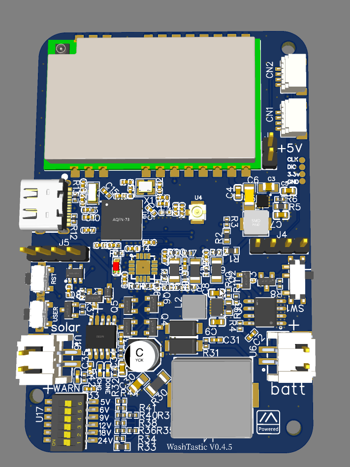
washtastic V0.4 now has ipex for ble and i moved the bootloader programming pins to the edge so u can use one of those pogo pin clips :)

5x v0.4 😅 not planning to order atm.

i can get 10 V0.3.5 for the price of this almost

nvm yes, i can get 10

We have another dare devil 😅
More v0.4 in the wild if it works 🤣
I need to also get on that boat but hella expensive compared to 0.3.5
Gotta raise my selling price again at that point 🤣🤣🤣
Maybe 100€ or 120€ per device 🤣🤣
68,5€ per board for 5x so ye 120 prob lol
@finite palm if u need help flashing the bootloader just send a message :)
And i need to create new diagram for 0.3.5 😅
Is it possible to export or share out an order? I'm tempted by this project but am afraid I'll botch the PCB order as I haven't done them before
Sadly no 😅 but i can guide u
Find 4 other friends and you're on to something
I have a work group of embedded engineers that I think would each like to have one
They're in the midwest and just barely out of range of each other with the normal boards
1 is never enough!
Hey guys! 👋
I've started an order for 0.4 but there are a few parts it's saying are out of stock... So I'm just working through that 😅 (I'll post here before I hit go)
I wanted to ask (if ok to ask here) what kind of solar panels everyone is using successfully? I've been using 10W ones with the older 0.3 version (with just the 5V solar - no voltage switching) and I can't seem to keep my Washtastic nodes running long term. I've even tried 12V 10W panels using a separate CN3791 charge controller and they're still slowly trending down.. I've been needing to revisit them once a month or so to swap out batteries (using 8 x 18650s in parallel). I'm wondering if I just need bigger panels, but would appreciate anyone's insight who has successfully run long term solar!
The 68uH inductor is known to be a problem child 😅 i did find a replacement and it's mentioned in GitHub
i currently have v0.3.5 running and its charging fine
dont think nobody else has reported charging issues

thats interesting
This has been my general experience 😅
I've tried both the solar port and an external one and im getting the same result
hmmm.... thats quite interesting
does the leds on the board light up when using solar?
Test setup 1 was this panel using the onboard ports... https://www.amazon.com.au/dp/B0DF32RPMJ

【Enhanced 3-in-1 Port】The solar panel kit features a Barrel DC port, along with adapters for Barrel Plug DC to USB-C and Barrel Plug DC to Micro USB. This versatile kit is compatible with DC 5V rechargeable battery cameras that have Barrel DC, Micro USB, or USB-C ports. Please note, it is not des...
Yep, the charge light comes on
all i can say the usb c wont charge it seems 😅 even tho in theory it should but i guess the lora draws too much current to do anything
The nodes aren't in direct sun... they're all under trees, but they get a lot of indirect sunlight with ~1-2hrs a day at least of full sun
Ohhh sorry I forgot to say -- I didn't use the USB connectors, I cut the cables and put a JST connector on it to go to the solar port
good
but ye thats something i havent been notified nor have seen to be an issue
not sure if its something with ur unit or what
Hmmm OK, thanks for letting me know -- I'll double check everything im doing again
Nah I've got 4 of them all doing the same thing 😕
V0.3.5 and v0.4 has better charging anyway 😅
I'm wondering if I possibly did something wrong in ordering from JLC and something is on backwards or missing
Brisbane, Australia
So usually sunny but its winter now... which is still like 16*C medium sun
ah, if u were closer i could have bought one from u to test 😅
Haha well if I can't figure it out I'm happy to send you one for science lol
Currently I'm testing using this external charger board...

Same CN3791 as you have on the board I think, but I did this as an isolation test
and with a 12V panel about twice the size of the other one... and It's still happening 😅
The screenshot above is from the external 12V one
(sorry brb, kids need me 👶 )
understandable xd
what board version u have?
i think 0.3.3b was the last one with CN3163 and everything after that now has cn3791
if v0.4 works might just switch to that tho its way more expensive 😅 0.3.5 will still remain as an cheaper alternative xd
also when u get it and if it works could u tell me what the ina3221 is reporting
ch1 should be negative while discharging (battery)
ch2 should be positive (3.3V to nrf)
ch3 should be positive when solar plugged in (solar)
Hey David from Brisbane, here ElectricFish from Canberra... here similar setup with same external solar charger and 12V 5w (Jaycar) panel. Here surely less sun in Winter but batteries charge full. Sudden brownouts randomly after 1-4 weeks operation it seems with the earlier 0.3.1 board here. Trying to to test supercaps to stabilise internal voltage. Will see...


hmmm and here I thought I was alone on my random "sleeps it never wakes up from" issue I've been seeing on my mobile boomer. I'm using a 0.3 with an external charge board, but its routing to the washtastic charger and the battery is coming off the washtastic....
@olive basin How is board version 0.3.5 ? Any issues ?
Haven't noticed yet
Well maybe reduced ble range on promicro 🤷♀️
Trying to talk AlletCat into making an enclosure for it..
If v0.4 was similar layout would prob work too but is not 🤣
And it's 0.1mm longer too xd
Taller
75mm vs 76mm 😅
Why no pic 😢


If you could harmonise the hole spacings, I think you'd be ok
Is there any way to do that?
Heya @pliant kiln ! Thanks for sharing this! That's an awesome build! 💪
Yeah I have an earlier version... I think 0.3.3 -- but I think a very short-lived version that had reverse polarity on the through hole connectors on the battery 😅
Hopefully these 0.4's I'm about to order will work perfectly!
Heya @olive basin sorry for the slow reply -- it's been a tough couple of days 😅
I think version 0.3.3 is the one I have. It was me messaging you a couple of months ago via GitHub with the reverse polarity through hole battery connectors... so that version 😅
I'm just working through my 0.4 order now -- I'll post a couple of screenshots. Would appreciate if you wouldn't mind having a quick look to see if I've got everything right (I'm a software person... not so good with hardware)
ah
gotcha 🤣
I guess just tick all of these...?

yes and no 😅 theres one cap that for some reason is wrong, just open it and see if its a smd component
the wrong one is a through hole

click the box with alot if info like the part numver (CXXXX)


ye the bottom one
OK cool -- looks like it has the same one as the C1, C15, etc. now...


argh
XR1265-680M


ye that one is not basic part
What should I search to find the right part...? Sorry it's giving me 12K+ results on 32Mhz search 😅

ye the first


lemme check

Thank you 🙏

Those are my guesses... but I have no idea what im doing 🤣
dis good
good
should be good if its 511k ohms
Yep I think it is from that tooltip
Here's the end result! 🚀

Oof... I see what you mean about this version being more expensive 😅
indeed
That's ~$250 USD, so about $50 USD / board?
Haha well I've come this far 😅
i think i got it to around 60€ or something after shipping and tax or was it closer to 70
when i checked
know any good JLC coupons? 🤣
Yay I do!

Alrighty, order submitted
now I wait
Thanks for your help with this @olive basin ❤️ ...and of course for the board design too 😅
@olive basin Do you have demensions for 0.3.x and 0.4.x boards ? I don't think the 0.4.x board shouldn't have an enclosure made for it just yet, since it's still being worked on..
@olive basin You should set up a patreon.. ;P
Technically i do :) and Also u can sponsor on GitHub
Hold on
Tho id much prefer if ppl used GitHub :)
Ah
iirc patreon directly deposits the money to me and it doesent go through them and that is not allowed in finland 😅
if a company pays me, like twitch then its allowed
Ah
Heya @olive basin I just got this back from JLC... what should I tell them?
For H1, we cannot find the corresponding pads on PCB. Could you please point out the pads on picture?
Your early reply will be highly appreciated, thank you so much!

I'm guessing just tell them to exclude it...? Looks like header pins that maybe shouldn't be there?
ye do that 😅 those should not even be in the bom xd
ill have to see
thats interseting
H1 is the CLK, DIO, 3.3 and gnd balls
it doesent have 3d model lol
or that header
oh
oh
😅
i got it
fixed now xd
but ye its not needed
v0.4 has the bat and sola plugs in different place than v0.3.5
Haha cool cool thank you!
ye np

Nop
It works from GitHub too, if you link the raw
a but u cant layer them ontop of em
I was just thinking if you align the holes, a lot of these will be deployed in enclosures anyway
hmmm
If you align to the raspi holes, you get bonus points
(I might make a PoE baseplate on the same holes, but with mounting slots. It's a frequent request.)
Note just the mounting holes, not the overall size/shape.
It's definitely easier than the RAK or the original Arduino uno
theres noway to do the holes like pi without moving alot of components
on v0.4
actually
thats best i can do on v0.4, the third hole is no go

Just having them in a straight line might be enough.
Just thinking about that "M3 grid" stuff
those holes are 2.5mm so i guess would need to make em bigger
i reverted back and they should be aligned
maybe

idk if they are aligned 🤷♀️
they look that way
You can check the x/y cords of the holes...
🤣
well well look at that
they are at the same x
now both are,
tho v0.4 they are in different spots than v0.3.5
Meh, can't win them all
yee
nah wtf did I find 
https://washtastic.com
Tf
tbh other than our dms I am not sure where the webstore is 
aight I've found it again hah
I wonder if i remembered to change the price


Heya @olive basin 👋
Exciting news! I have the 0.4 boards!! 😄 

I'm just setting up to flash the bootloaders on them... the documentation for the ESP32 flasher firmware says to connect to SWCL and SWIO on the NRF... is thatthe headers labelled TX and RX on the board.. or is it the I2c ones?


Here is the one that will probably be sacrificed to science when I make a mistake doing this 😅

Legend, thank you! 😄
Just setting up the ESP board for flashing now... will post results! 😄
also those pads are so u can use something like this https://www.aliexpress.com/item/1005004869027755.html 1.27mm 4P
single row
That's awesome! I'll order one for the next batch (assuming this all works) 🤣
@olive basin is there supposed to be a password on the web ui for the ESP32 flasher... did you get that?
I cant see in that discord thread any mention of it
I got the WiFi configured on it... but then when I try to hit the web UI it's prompting for a login

I might just try flashing again... in the YT video hes getting this, which is totally different to mine...

In the git repo there's .html file u gotta upload
Of the esp flasher
GitHub
This software brings you the possibility to Read and Write the internal Flash of the Nordic nRF52 series with an ESP32 - atc1441/ESP32_nRF52_SWD
Ahhh got it, thank you @olive basin !
np
Is that an embedded pro micro 
indeed
madman
i havent had a chance to test it myself 🤣
@olive basin sorry more questions... do you know the login?
It looks so clean 
what login?

hahaha
Woohoo

if it says nrf locked then u gotta erase nrf
A mobile solar washtastic node is sounding quite intriguing.
i mean could prob make a non 1W washtastic
did u get it?
I've got the ESP up and running... but I can't get it to connect to the NRF
I'll do a quick video!
This one has been going strong on the roof of my car for a few months with the popular Soshine panel. I ended up swapping in two 18650s instead of the lipo pouch for a little more run time. But I do get a ton of sun here so results may vary.


#1346425369246302258 :)
plus the newer 0.3.5 has better charging circuit

indeed
Alrighty... brb soldering lol
that was gps connector where u connected it
haha ye

woohoo
Instructions for updating or recovering the bootloader on nRF52 devices.
Is it the uf2 files from here i flash?
(im taking photos and documenting as I go btw so I can put together a guide if you want)
no wait it was hex
GitHub
This repository contains the official firmware for Meshtastic, an open-source, off-grid mesh communication system. - meshtastic/firmware
ye sure
6.1

Did u hit flash uploaded file?


Could u maybe take one board and maybe try plugging usb in :)

Woohoo
hokay USB time
Chg LED solid red... but nothing showing up on computer
Double press reset no resposne
Flip da switch maybe
Oh - battery?
The usb alone isn supplying anything :) the switch cuts power to the nrf
That led is a good sign tho :)


Bluetooth is being weird
Hm?
INFO | ??:??:?? 224 BLE Connected to iPhone
DEBUG | ??:??:?? 224 BluetoothStatus CONNECTED
INFO | ??:??:?? 226 Ended BLE connection
INFO | ??:??:?? 226 BLE Disconnected, reason = 0x16
DEBUG | ??:??:?? 226 PhoneAPI::close()
DEBUG | ??:??:?? 226 BluetoothStatus DISCONNECTED
INFO | ??:??:?? 227 BLE Connected to iPhone
DEBUG | ??:??:?? 227 BluetoothStatus CONNECTED
DEBUG | ??:??:?? 227 [Power] Battery: usbPower=0, isCharging=0, batMv=4152, batPct=97
INFO | ??:??:?? 228 Ended BLE connection
INFO | ??:??:?? 228 BLE Disconnected, reason = 0x16
DEBUG | ??:??:?? 228 PhoneAPI::close()
DEBUG | ??:??:?? 228 BluetoothStatus DISCONNECTED
Its kidna looping trying to connect
Tried on iPhone and Android and both do the same thing
It starts to try the pairing process then just loops over and ober
Haha I mean for my use case BT isn't a big deal 🤷
It's nice to have but im using them as repeaters with managemnet over mesh
I'll try doing all the config over serial now

voltage reading works
On android u can do serial
How about ina?
Good call -- switching to Android serial
Will enable telemetry module and check

Lora is up
Nice

I guess 1 is battery... 2 is 3.3v..?
Ye ch2 is the mcu
Anything else you want me to check?
Hmmm tho ch 1 should be positive if charging
It will be discharging now because connected to phone
I'll connect to computer, sec
I mean i think ch3 also will display usb
Don't remember exactly
Since it has 5v and 2mA xd
Hmmm its not sending me a new telemetry packet lol
It's not fast lol
Nope lol... will report back on this... evenetually 😆
What do you want to name this node? 😛 You get naming rights!
Oh ye flip 5v on the dip switches :)
Ooh the light went green
Guinea pig lol
Green "Done" light is on now
I guess that's the CN3791 telling us its not charging now...?

Did you flash the bootloader, and then the firmware?
Yee
Now to figure Bluetooth 🤣
~4.06 is right on battery voltage
Just flashing a second one now to fault isolate on the bluetooth thing
Also I used 2.6.11 firmware -- new alpha so it could just be a FW issue
Will put 2.6.4 on this one which is known good for BT on the 0.3 version
@olive basin bluetooth is working now!!
On both boards.... 🤨
Wha
Sorry for the false alarm... It could have either been because I still had the ESP flasher connected (it was soldered on.. but working with it off now)... or maybe just a weird bug in the new firmware
thats prob why its doing that
hm
So the main battery voltage says 4.16, but the INA says 4.08 -- and my multimeter agrees with the INA
close enough
So there's a bit of a discrepency there but good enough
Yep, I'm not complaining lol
well its a voltage divider so ye
2 boards looking good!

I've got a solar enclosure outside with a 0.3 board in it now (one of the ones I was having the issue of slowly discharging over time with) -- I'll swap it out for this board and let it burn in for a week or so! 😄
Thanks again for all of your help with this @olive basin ! ❤️
I'll put together some instructions -- do you want me to push as a merge request to the wiki on your github?
Also - let me know if there's anything else you want me to test on these -- happy to do so!
ye sure u can do that :)
But for now... it's 1AM and I'm off to bed 🤣
Good night! 😄 👋
night
Wait, so does 0.4.x work now ?!
welll
yes but no
😅
if u dont care about bluetooth yes it does seem to work
tho it prob did work on the first version too but it just didnt have the external 3.3V converter
i just realised i had routed di01 under the antenna 😅
oops
actually had few
I think Bluetooth is good!


Overnight report -- seems to be averaging about 20ma draw.. and this is on a relatively busy mesh of 100+ active nodes on medium fast
In client mode


Washy 1 is outside soaking up the sunshine 🌞

INA219 is getting the solar panel on channel 3! It's a 12V panel, so accounting for MPPT that ~11V sounds about right!
Although the current sense is backwards 😅 might need to change the direction of the current flow to the INA so it picks it up as positive current instead of negative
Yeee thx :)
And its ina3221 btw :)
I wonder if i could fit bme280 on that board
Since it already requires standard assembly 🤣
Well atleast ch1 and ch2 are positive current 😅 and now i realised i might want switch ch2 to also display the lora consumption 😅 since it's only showing nrf52 but idk, ch1 still show's it anyway so 🤷♀️
Yes.. ;P LOL!!!!!!!!!!!!! Go w/ a 680 if possible.. LOL
This is what I have for my INA3221 on my rak19007 in lowes solar node..

I guess the 3 channels should have told me that... 🤦♂️ 🤣
This would be awesome! I'm going to be hooking one up to I2C on each of these

@olive basin maybe a false alarm on those negative amp readings.... it has now jumped over to positive 🤣
Yes but its hella expensive
True..
Its like $10 on diginey 😅
interesting how it didnt work yesteday
I just realised something
i have set the max charging current to 2A 😅
wont matter much if the panel cant supply it
if math
correct

Would be surprised if they didn't
Literally connected to the same trace with ina 🤣
So, ble is okay?
Yep been working perfectly since
It was just that one time.. happened with both iOS and Android, but after a reset it’s been perfect
Honestly I would suspect firmware.. only happened on the one I put 2.6.11 on and only at first
The 2.6.4 one works perfectly from the first try
Different board and different firmware so.. results inconclusive it it works so meh 😂
Lol
Ok I'll bite, where can I git more info on ordering one of these E22-90030S w pm NRF52 ?

GitHub
PCBs i've made for meshtastic. Contribute to valzzu/meshtastic-pcbs development by creating an account on GitHub.
0.3.5 is pretty well tested
0.4 is experimental atm
Also make sure to post dome pics or videos in #1346425369246302258 once u got something to show.
10 more

Not gonna lie, these are beautiful.
Hahahaha
Kinda makes me wish I'd ordered the V0.4 in Purple 🤣
It does look good
My OCD wants me to ask you to move the one thats upside down in the bottom row up to the top with its friends 🤣
I like black PCBs..
But out here in the desert, where it can get 120f/48.8c in the shade, black isn't the best color.. LOL
-# white PCBs
@mint trail read from here :)
TLDR; its been tested
Awesome!!! Time to update https://github.com/valzzu/meshtastic-pcbs/tree/main/WashTastic#v04x
i was supposed to remove that 😅
oops
done
now its a warning xd
@finite palm hows the bootloader flashing wiki going?
I'm new to this, so I grabbed the 0.4 gerber file, uploaded to https://www.seeedstudio.com/fusion_pcb.html and it gives an error about "no NC drill file" http://support.seeedstudio.com/knowledgebase/articles/1977138
Check the folder, but they should be there. 2/3 of the solutions are to ignore it.
Roger that.
For everything that you want them to solder on, you just look up the manufacturers part number and add it to the BOM_1W-meshtastic-node_0.4_connectors.csv
Is there's not a bom included?
I used the .csv, but then like part 16 12pF C11,C12,C18,C20 but no manufacturer or supplier part numbers.
I'm probably over my head, it's a capacitor, but I don't know the type size etc, nor how to figure that out.
SM04B+AC0-SRSS+AC0-TB(LF)(SN) I look that up and I see nothing with the AC0, but can find SM04B-SRSS-TB
I'm finding that +AC0 in multiples, so that must be something with my formatting, disregard that.
That had to do with UTF-7 vs UTF-8 encoding
are we looking at the same bom?

footprint is C0402, aka tiny
Nope, that looks like the one without connectors
In your image, 14 through 19 don't have part numbers for them.
For the ones that have the LCSC number, I can get the MFG part number, and see if they have it here: https://www.seeedstudio.com/opl.html
ok, but if they don't have a part number, normally JLC just match it to their basic range
I dunno what seeeeeeed do
oh, that looks tedious, if they don't have even basic matching
JLC then says The below parts won't be assembled due to data missing.
U8,U11,J1,U12,J3,J4,J5,J6 designators don't exist in the BOM file. Is that normal?
It seems like one doesn't have to manually look up the parts on https://www.seeedstudio.com/opl.html but they need at least a part number they can cross reference, I see how JLC does it, they look at the footprint and find the closest match.
Off topic, but is there a way to have posted links not get expanded?
Thanks, that gets annoying quickly
Yup, there are some that are not included cuz they don't need assembly, like the through hole headers
Also jlc is probably cheaper than seeed anyway
I had done it through there, but the were missing some parts so I wanted to see if it would be the same with seeed
As for the 68uH inductor u can find the part in GitHub under v0.3.5 atleast
That is one that JLC had me search for but they had different sizes on all of them
Ye, idk why it's not finding the correct one
PCB cost was like half price on seeed, but never got through the components and placement part of it.
Maybe not half, I closed the window but it was 4 something vs 7
what

And about $8 shipping, slow boat.
Disclaimer, I just uploaded the gerber zip, so if anything needed to be changed I probably didn't do it correctly.
No components and no assembly as they wanted part numbers for everything when I tried to submit it.
But I feel like I'm not familiar with this kind of process that I would probably mess something up trying to figure out all of the part numbers to put in. Could probably get most of them by copying from what JLC decides.
yee
Should probably start with something simpler/cheaper or just buy as part of a group purchase or something.
theres one component that jlc might think is a through hole so make sure u catch that
fair
#1377910167240441866 🙃
🤣
I like the size of the seeed nodes, Would have been awesome if they could have made these fit the XIAO dimensions: https://www.seeedstudio.com/Wio-WM1110-Module-LR1110-and-nRF52840-p-5676.html
Flushable, lol, ever see the show Adam Ruins Everything, with the flushable golfballs, 🤣
nope
build it
It's just too big to fit at 20x20mm. If somehow they could have made it thicker instead.
Hey! Work in progress, sorry -- will try to finish it over the weekend. I need to go back and grab some screenshots I missed along the way!
alr no worries
yeah, I didn't pursue it because it was wider than 18mm, which is my idea of what is able to fit in a sensible setup
but we're being picky. Build it!
BTW, my view is that the xiao format is cute for project work, but the lack of IO is annoying, and the 2-row breadboard-friendly format is only useful on a breadboard. Beyond a certain point you want JST.
i know have an etsy store https://valzzu.etsy.com/
tho will only be shipping in EU countries for now


Not that I can order from Canada but what does the support option get you?
a worthy cause!
indeed
Washtastic running 2.7.0..
yes and switch turned off :) works fine when switch is on and node is drawing current
tf, just got another washtastic order 😅
@olive basin My (recycled) solar panels should arrive very soon, so I'm starting to get ready to order a batch of washtastics to provide backup communications in my city. I'm a bit worried about there not being load sharing, and thus the charge cycle not terminating (this normally terminated if current drops below 16% of charge current, which would be 2A in this case, so 320mA), which would impact the safety of the battery. What capacity battery did you connect to the 0.3.5 version? Do you see the CHG LED turning off sometimes?
Secondly, I just saw the CN3795 charge IC, which also does the same solar panel input range, but also supports cells of a different chemistry, and is literally just 2 resistors extra compared to the existing CN3791. I don't want to ask for a redesign (again, sorry :/ ), but wanted to bring this to your attention that it exists, and is maybe useful to get a longer life out of lipo cells (they apparently live a lot longer if you don't charge them to 100%) or to be able to use fancy LTO batteries
or even LiFePO4 batteries, which are safer
I think she might be asleep, but she's aware of teh CN3795. I don't want to second guess her design decisions, but the CN3795 has a higher minimum input voltage (6.5V iirc) which might mess with battery charging, and also the addition of a second voltage divider requires another bank of switches, which would require a redesign.
righto, that makes sense 🙂
10A, the node is outside so idk
Idk how one would even add power path
I know its i thing and i did a variant of it but never released it. Don't remember how it looks tho 😅 not sure if i did it on 0.4 or some earlier version
Plus it would still need to 4.2V s I wouldn't damage anything
And not 5V or 15V
I can do some testing in the weekend
But ye, there's no real good way to do load sharing
if you have a 12V solar panel, and place a linear regulator on it (in parallel with the MPPT), can you do load sharing off of that? sure, you'll lose some efficiency in the solar panel, but that should be fine, I think?
Might be worth watching this video:
https://www.youtube.com/watch?v=f2yMs-JAyQM

Following another video where I showed that you can make a handy emergency backup light from salvaged lithium cells, I got a few messages implying that with a load connected to a cell the charging may not stop and risk overcharging the cell.
To be fair it does look like that is happening, but in reality its down to the way the TP4056 and its ma...
I did, but I think this assumes that the battery capacity is matched to the configuration resistor of the charge chip: if you hang a 10 Ah battery on it, there will be a much higher terminal charge current then with a 2 Ah battery. If you then also add the load of the microcontroller, it could well be that it does not terminate the charge on a 10 Ah battery, and does on a 2 Ah battery? Or am I misunderstanding something? In addition, the slowly charging, then discharging probably is also worse then just leaving the battery unused when there is sun?
on 0.4 the usb power takes priority over solar so maybe something like that could be done for load sharing, just cut the battery off and feed like 4V to the line 🤷♀️ but that then adds more complexity and components
and brings the cost up possibly
the node is drawing like 20mA constatnly while idling so 🤷♀️
ill report back when i get home
since i have deployed 0.3.5 and the battery is full so i can check what its showing
but ye it might be worse to keep discharging slowly and charging again
i doubt the battery capacity makes a difference


but 🤷♀️
You're supposed to stop charging in the constant voltage phase when the current goes below a certain percentage of the capacity, most commonly 0.1C (so for a 2 Ah battery, once the current goes below 200 mA, it should stop applying voltage). Washtastic is using the CN... chip, which stops charging in the constant voltage phase when the current goes below 17.5% of what the current sense resistor is configured to. So if it's configured to charge at 2A (which is the case, with the current configuration), it will stop charging when the current goes below 350 mA. This is more then fine for a 2 Ah battery (it even stops a bit earlier than it's supposed to), but if you attach a much bigger battery (for example, a 10 Ah battery), you also stop charging only if the current goes below 350 mA, which might not happen since this is a lot less than 0.1C (which would be 1A). Note that this 350 mA here is not at all related to the capacity of the battery attached, only to the current sense resistor, but to have a correct charge termination condition, it should be related to the battery capacity instead.
And I mean, in practice, it might just be fine, I'm just a bit worried about the battery degrading fast.
I think you've answered the question there. Node draw is 20mA, terminal charge current is 350mA
It's pushing that a bit later in the cycle, but not much.
If you genuinely want to charge to a lower voltage, use a multi-chem charge system and set the terminal voltage to 4.1
I tuned my micro-mppt to that.
Remember there is also an overcharge protection chip as well.
Kicks in at 4.25V iirc
I can lower the max charging sense resistor so it's at 1A
Iirc it should be like 0.012ohms for 1A atleast thats what i remember when i checked what it would be
yeah, I guess I communicated it a bit confusingly of what my actual questions are, I'm afraid
- with a 2 Ah battery, is the system safe? (does it stop charging in constant current mode) -> yes, since node draw is 20 mA, 0.1C is 200 mA, but it already stops at 350 mA, so this is fine
- with a 10 Ah battery, is the system safe? (does it stop charging in constant current mode) -> unsure: node draw is 20 mA, 0.1C draw is 1A, but it will only stop charging if the total current drops below 350 mA, so this might not happen, is very depending on what current the batteries themselves draw in constant voltage mode. Lowering the charging resistor to 1 A would be worse, since it would then only stop charging if it reaches an even lower current.
- with a 2 Ah battery, how bad is it for the batteries to constantly charge/discharge them slowly in cycles (like in the bigclive video), compared to having load sharing, where it would charge then disconnect during the day, and discharge during the night
I'll check my node on Saturday what the node says its doing
I think that question is better left to #solar-power
It's a generic problem we all face with larger battery packs
options I see for my own system if I want to make it more safe/better for the batteries (I'll soon have a pallet of 12V solar panels, recycled from parking meters, and want to cover my city in meshtastic nodes)
- do load sharing, with a linear regular, to avoid more cycles on the batteries
- use the multi chemistry CN chip to be able to use a lower battery voltage or to use LiFePO4 or LTO batteries
good point 🙂 English is not really my first language, when I find some time, I'll reword it to give people outside of washtastic some context, then post it there
It's just that washtastic seemed to be the most polished meshtastic project for solar repeaters, and does almost everything perfectly imo
i think i have a defective lora module
it gets hot semi fast
expecially on spot where the ebyte logo is
also its not being detected
only if i know had a thermal cam
something is indeed wrong
i tested it with my psu and when i start power the node on it draws 30mA for few seconds and the jumps to the max of 500mA that i had set
i tested with my multimeter and nothing was shorted externally
what on earth is going on
soldered another washtastic and it cant find the lora but this time its not heating up
all solder joints look okay
@meager spruce had bad luck with a promicro today, too.
I think we're just not having a good hardware day all round
ive had these promicros for a while now
but bad promicro wont explain the lora module heating up like crazy and pulling like 490mA
tru
i gotta get one working one tho
phew
third times the charm lol
i need more promicros 😅
get one of these while iyou're on Ali:
https://www.aliexpress.com/item/1005005499263696.html
note: 1.8v operation.
Gyro & compass for BUI
Ah, not like i have any node with a screen 🙃
Expect my v3
And t3s3
@remote jungle

Stopped at 4.05V
Nvm
Now its 4.17
maybe for flushable when it has a screen lol
and it has a case u can have on ur wrist
seems like it started to charge again 🤷♀️
but yes, it will terminate charging
alrighty 🙂 any idea of the cycle time of charging / discharging? okay if not
although, sun has gone down here, so there also probably
didnt check
i guess it also depends on the size of the battery
that one was 1200mAh
ah, yeah, that one we calculated should cycle, it's the 10 Ah one I'm worried about
I'll check the my base since it was so late/raining last night lol


now gps as 3d model xd
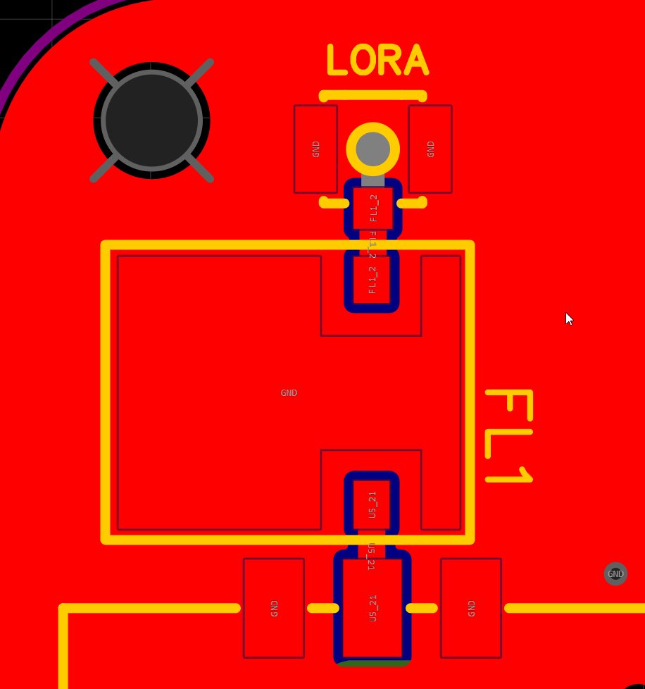
just realised the filter is pain to solder 😅
need fuck ton of heat
what filter is that?


DigiKey Electronics
Tilaa tänään, lähetys tänään. DBP.868.U.A.30 – 868MHz Taajuus Kaistanpäästö RF-suodattimet (radiotaajuus) 4MHz kaistanleveys 3dB 2-SMD, ei johtoa toimittajalta Taoglas Limited. Miljoonien DigiKey elektroniikkakomponenttien hinnat ja saatavuus.
need us version too now that i think of it

DigiKey Electronics
Tilaa tänään, lähetys tänään. DBP.915.V.A.30 – 915MHz Taajuus Kaistanpäästö RF-suodattimet (radiotaajuus) 5MHz kaistanleveys 3,2dB 2-SMD, ei johtoa toimittajalta Taoglas Limited. Miljoonien DigiKey elektroniikkakomponenttien hinnat ja saatavuus.
is the filter always worth it? it has 3dB insertion loss, but I guess when close to a cell tower or something, it might be useful?
u dont need to use it tho
and do you need a coax to the filter and then another coax away to the antenna, or does the radiomodule have a pad for the RF signal, so you only need to put one ipex connector on the PCB?
nvm
I looked at this foto, now it's clear
I'm interested in the comparison, if you ever make one 🙂
I guess I can always add the filter afterwards if I really need it
Tru
Hi Iris - quick question: what job do q3 (I assume just power on/off the nrf and ebyte?) and q4 have?
Q4 is reverse polarity protection on the battery and q3 is for powering the whole board

MHP50!
I do have a hotplate
if you add -D EBYTE_E22_900M30S to your variant, the configured Tx power becomes post-PA tx power 🙂
so you can just set any number you want, it will then get correctly limited by firmware
e.g. if the regional limit is 26dBm, it will get limited to 26 and also save to user prefs as 26
Welll im using promicro variant soooo
And users ain't gonna be compiling their own firmware 😅
haha, if you are selling them with firmware, or if this variant is getting built elsewhere only with this module, i'd suggest adding that define
-D EBYTE_E22_900M33S also does the same gain calc + sx1262 limiting
and setting licensed mode still overrides that as before, but still clamps the sx1262
Files are available on GitHub but I'm using promicro diy variant
icic
the main issue with building -D EBYTE_E22_900M33S is that you can't set >30 from the iOS app
For initial flashing i can do that but what happens if ppl update their nodes?
Since they just download the file from flasher
That will ofc remove the thing and then shit happens
I mean could build my own firmware and redirect ppl to download it but thats a hassle
hm, so i would say that the promicro variant should have EBYTE_E22_900M30S defined
i'm still trying to think of a better way than having a different variant for every different EBYTE module
an easy way is for the gain and sx126x limit be a user pref, but it really shouldn't too...
but i don't think having many many different variants that are extra level would cause any burden to meshtastic devs
Probably not but they would not be in the flasher
Might need a second flasher to dispense DIY firmware.
It's something we've discussed a few times.
I've made a start, using GitHub actions

i could add a smd gps antenna on the board 🤔
This groove connector is killing me.. ;P
wdym?
I don't have groove cables for my I2C devices..
theres also a header
Yup, that's what I'm using now..
But had to solder header..
was to lazy when I built it..
i can add it to the assembly
Nah, it takes me all of 15-30 seconds to solder the 4 pin header..
I'm looking into solder fountains now... HAHAHAHAHAHAHAAH
dem
only when you’re sure you no longer need new neural pathways
Neural pathways are so 1900s.. LOL
holy shit, somebody ordered 2 washtastic from spain 😅 they have yet to pay
atlest etsy hasnt registered
just sent the files with the filter to pcbway and elecrow so well see what the price is for 5 compared to jlcpcb

this one
initial estimate without componets is
pcbway $73.14
elecrow $83.52
jlc 216.24€ for the whole thing.
minus filter, bme280 and qwiic cuz out of stock
For 5 PCBs?
So JLC will be $15 or so for the PCBs...
Just for the PCBs? Delivered?
that price it the full one with tax etc from jlc
Oh, um...
5 boards is 216.24€ so 43€
per one
ofc plus the filter
2,34€ for one
and cant forget promicro
so 50€
or so
PCB only

ye board is cheap
That's 2x 5 boards, with coupon on one order
assembly is the most expensive
Oh, the pcbway and Elecrow include assembly? Sorry, I missed that.
PCB + assembly but no components.
yes
Ok, I think you can get the BOM cost from JLC?

pcbway

elecrow
idk why the total price is different
cuz if i count evenrything its more
Remind me why pcbway is cool?
Cool to people who have too much money...
yeee
mainly seeing what elecrow can offer if i'm gonna sell the boards
and use their production
since if i ship to china its like 44€ so ye
even tho jlc is cheaper shippin costs fuck ton
okay got elecrows quote, its $275.03
mind u it has bme280, the filter and the qwiic connectors
tho it does not include tax
295€ with tax
so 59€ per node 😅
still waiting for pcbway
@olive basin , you're in the EU somewhere, right?
Okay. I need to find somebody stateside to coerce into doing a batch then.
Might have some WashTastics on sale globally at somepoint
Pcbway

So elecrow is the second cheapest
@heady mulch
Lead time on both about a month
I wonder what seeeds price are 🤔
Have you always had Duty & Tax ?
EU
And i selected the shipping method that has ir
Cuz i don't wanna deal with customs if i can choose
i hate seeds bom requirements
they need the manufacturer part nuber rather than jlc, digikey etc numbers
argh
also they need the link for the item
aaaaaaaaaaaaaaaaaaaaaa
welp
time to add the mnp to all parts

But if you order 50, they're the same price per piece as JLC when ordering 5 😄
And they're waiving 500$ in engineering fees!


jlc is still cheaper with standard assembly 😅
still missing the filter and qwiic connectors

Qwiic connectors? JST!
The cheaper, more universal cousin

