


1 messages · Page 2 of 1
came up with this potential design
have to wait for the sensors to know the right offset for the filament path, I like the wipe mechanism this has, will probably add a screw for it
if filament doesn't smoothly go through, I think I'll try a trap door approach like that one
just one that rotates out rather than folding, since that way there can be two doors on one servo, top door pushes the pellet into the 'chamber', where the sensor makes its measurement, then the next door allows the pellet to fall out
New day, new set of issues, got a timer too close, discovered that the rpi wasn't using its gpu to encode the camera stream
Switched back to mjpeg for now, this camera is kind of terrible anyway
I have so many phones with good cameras laying around, I wish it were more practical to use them for this kind of thing, I don't want to have to worry about the battery if left plugged in
One option would be the atomic pi boards I have laying around, way more powerful than the 3b, but also larger, not the form factor for mounting on leviathan and would need a separate usb hub
Ah, finally figured out what I was missing for stallguard homing to nozzle, the regular homing is working fine, but part of why I got the thr36 specifically was to have the diag pin on stepper for homing to nozzle
I'm not following
If you have the diag pin on the extruder stepper, you can have it so happy hare pushes the filanent until it experiences resistance due to the nozzle
ohh got it
It's not a big change if you have the extruder to nozzle distance set properly, but it sounds cool so I want to give it a try
oh I guess one benefit is that you apparently no longer need any sensors on the toolhead
I like to have it before the extruder
I did stumble across an inline filament sensor from annex today, where it just goes in between the bowden, kinda like the belay
but to get to the extruder I find the collision sensing to be pretty reliable
hmm, just trying to tune sensitivity as normal doesn't seem reliable, maybe I should have it reduce the stepper current first
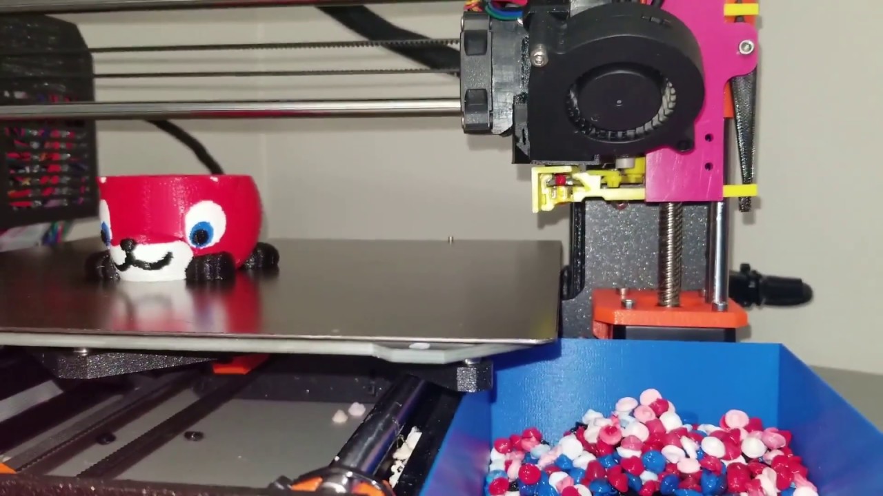
color sensors are in, dimensions are good, printing the parts
for now just in pla since I have so much of it to get through
electronics fit right, one part needs an adjusted reprint, then I can start prototyping the sensor code
curious to see the outcomw
got it wired up and testing by just sticking filament in the path, sensor does work, but has a much narrower fov than would be ideal
not a deal breaker I guess if I can get the extruded plastic to not blob up and get stuck
else the approach of building a pellet and checking the top of that will probably be better
the onboard led is really bright though, which is nice
Tried mounting it, adjustment range is too large, hits against the rail when setting it high enough, so shortened that

Decided to have the nozzle sit slightly "in" the channel, figured I'd try using kapton tape as a barrier to prevent filament from sticking to the walls, probably need to remove the fillet on the edge for it to apply nicely
If kapton tape doesn't work, maybe a bit of aluminum foil
actually I might be overthinking it, I'll just print and see how it goes
one idea make the mounts under the extrusion, more parts but highly adjustable and easier to make stuff not collide
Ah yeah, that would be much better
looks a little wonky though
Yeah, but otoh that would even cut down on material further (already made changes which made the design much smaller last night) and allow for adjustment back and forth too rather than just up and down
Easier to place anywhere then
true
that design was born out of the need to wipe the nozzle with unklicky attached
(only managed to find it today, this was the one I wanted to send yesterday)
(or today? I'm lost in time)
Oh that's an interesting consideration, I just wipe the nozzle before starting all probing, the temperature at that point is 150c so there isn't any ooze afterwards until after probing is done and the nozzle is brought up to printing temp
I probe quite near the printing temp, like only 30 under IIRC
ah
ok redesign done, reduced print time slightly

Slight design errors fixed, going to be interesting to see how poorly the pla copes with having a hot nozzle in the purge channel
After verifying proper fit I'll reprint in abs
Good fit, just slight screw placement error, printing first "real" test in abs now
The 3010 fan for cooling the toolhead board is pretty effective, periodically activates in enclosure when it gets to ~63c, fan quickly brings it down to ~58c and shuts down, repeating every couple of minutes
Fits right, although the mount can probably be made thinner and having a back piece rather than relying on nuts for z adjustment would be better

For now I'm just going to debug it through the usb port, I think eventually I'll make it work kind of like an encoder, where the value it outputs goes between 0 and 1 every time the color reading changes meaningfully within say, 200ms, so you only need the 3 wires to a klipper mcu
Well that's no good

Time to think of another approach
For now I'd like to stick to printing lines rather than pellets, there's this kind of approach https://github.com/bombela/EjectionAssistedPurge

Purge the nozzle of a filament 3D printer into tray with motorized ejection - GitHub - bombela/EjectionAssistedPurge: Purge the nozzle of a filament 3D printer into tray with motorized ejection
But it requires 15s of cooling per line
The plastic sticks slightly to the side and starts the blob

Instead, what if I didn't tie measuring purge amount to the purge system, instead, have the printer print out all the combos involved in a print, and automate measuring the lengths
Looks like superslicer has a "pigment percentage" method for avoiding having to track purge amounts per color
Seems to be tuned empirically, but maybe can be tuned automatically
ok yeah, so by printing say a 3 filament matrix of swap purge lines and measuring the purge amount, you should be able to solve for their pigment percentage, then you should be able to solve for any other filament's pigment percentage with 2 swaps
ah actually no, can't fully solve, but can probably go by picking a pigment percentage value for one filament, restricting the range of values such that all other pigment percentages stay within 0 and 1
Finished writing the script to generate the pattern, just going to make it also print length markers
The percent pigment values could be estimated from that, but I'm not too sure how the info could be managed and easily submitted to the purge gcode
I guess the most straightforward approach would be to write it on the spool and remember to specify it to klipper
@sharp valve there are quite a few mmu purge stls, the main way I see it done is purge between every combination and tune slicer from that.
red to black - Xmm³
black to red - Ymm³
red to white - Zmm³
and so on, I wonder if we can determine how much each colour needs to be "over" and how much needs to "start", like where's the in between that's common for every possible transition and you just add those values to get the amount to purge for that combination
hard to explain
Yes that's what this "percent pigment" system seems to be, it's mentioned at the end of the ercf v1 manual, the approach is that purge amount = nozzle volume + multiplier *(pigment percent from - pigment percent to)
They just talk about manually setting the values, but if we know a bunch of purge lengths, we ought to be able to do something like least squares optimization to make a good guess of the pigment percent of the filaments
now I'm lost here maths are not my strength 😅
Haha I see, basically, the separable value, such that you can "add" them together to get the purge length, is "how pigmented is this filament"
The more pigmented, the longer it'll take to clear out
I might pick up some unpigmented filament to try to see if it actually is supposed to result in 0% pigment or if this is just an abstract value unrelated to the actual amount of pigment
like natural ABS for example?
Yeah
might be a good candidate, my guess is that since you're swapping from natural to something else there might be some amount to it, red for example my guess is that depending on the shade of red will have more or less pigment (same happens with food colouring) and since natural ABS is whiteish the transition might look like natural - pink - red
you will find a different behaviour if you try with transparent filament (petg maybe?)
but I'm pretty curious about this, having a way to at least do a rough estimate on the amounts needed
Yeah, I'm not sure how transparent filament would cope either
Plus, looking at solely the pigment amount also overlooks the material, so I wonder what additional factors would be needed to account for the purge needed between materials
so, my script generates this kind of thing, similar to some of the test pattern files online, but hopefully more customizable, the markers would help eyeball the purge lengths, going to try printing this and then try to see if I can get any consistent numbers for the percent pigment

yep
hmm

kind of works? the pigment percentages kind of make sense since afaik with pla, white tends to have more pigment, at it gets 0.71 for white, 0.6 for silver, 0.24 for black
but otoh I'd expect the values to settle down with alternating optimization of the percentages and the multiplier + nozzle volume, which doesn't seem to happen
it's also still not as good of a fit as I'd have liked
ah found my error, one of my constraints was wrong
ah this was backwards
if white was more pigmented, white to black would take more purging, but actually black to white takes more
one factor that this isn't capturing, which is probably part of some of the larger discrepancies in the calculation is that filament 0 and 1 are very similar colors, so the needed purge should be reduced
Tbh this is starting to seem like way too much complexity to add relative to the cost of pla 😅
True
Thought about it more, the pattern generation script is clearly worth keeping at least, I'm leaning towards thinking of other ways to do the color sensing thing again though
Been looking at other purge systems for inspiration

Create pebbles instead of purge blocks! | Download free 3D printable STL models
Purge the nozzle of a filament 3D printer into tray with motorized ejection - GitHub - bombela/EjectionAssistedPurge: Purge the nozzle of a filament 3D printer into tray with motorized ejection
Maybe a door mechanism is the way after all...
Ok yeah, I can modify my existing design to have a door, which would allow forming a pellet, letting it cool off enough to fall through cleanly, and then slide the door open, dropping it past the sensor, I think it should be able to read the color fast enough during the fall, else I'll just place another door underneath
Thinking of going with rack and pinion for the doors, although I'm not sure how I'd model them in cadquery
ended up just making the gears in blender, one door above the sensor to make the pellet on, one door below the sensor to drop it after sensing, both driven by a tall pinion gear
and a slide-in washer to ensure the pellet doesn't stay stuck to the nozzle
Ouch got a pretty bad jam
The retract before cutting the filament must have been slightly too long, had the remaining piece get jammed in the heatbreak
Had to take the hotend apart to get at it
Sliding mechanism works nicely, now to add stuff to mount the servo

The gear is way oversized though, can reduce the teeth by a lot
I dunno if it is going to work, but it definitely looks sick AF
E5Pro to M1.1/EVA3/Hydra/ERCF
What if the chute hole were conical? start wide and taper?
yeah that would be a good improvement, I've just been putting off figuring out how to make that in cadquery 😅
ah, shit, forgot you're using that. it's a learning experience, right? [cough]
hahaha for me, coming from blender, all cad is a learning experience
blender terrorized me out of learning any kind of cad. didn't know the difference back in 2001.
that changed later, of course.
18 years, lol
oh yeah, especially back then, the blender ui wasn't that good and there wasn't a lot of material on it
I picked it up ~2009, during my "when I grow up I want to be a gamedev" phase lol, was still a challenge, but I had all the time in the world back then
oohh, I remember that phase. I had a book called AMAZING 3D GAMES. It taught an entirely C-based game engine that predates even Quake. I was eleven and had no idea what I was reading.
graphics so bad i had nausea
Oooh
I only had access to ancient books the school library was throwing out on BASIC and electronics, didn't really learn much from them lol
ever heard of the Duke TIP program? not sure if it still exists.
Nope (haven't heard of it)
anyway, that's where I learned to actually program. 3 week college course over the summer in junior high or high school. learned Python and C++.
super fantastic way to have someone introduce the materials. there aren't a lot of good self-driven courses.
Oh that's really cool, I didn't really have access to any decent resources, due to my dad's job I was in Iran at the time, the school was terrible, friend group was the typical toxic teenage cesspool and my parents didn't think that anything I could teach myself could have any real value lol
schools are often less-than-conducive to really learning
Learning to code was mostly just about proving them wrong
Yep
When we moved to the next country, it was pretty good though, a software engineer relative happened to see my stuff, which made my parents more understanding, and I ended up being chosen for that country's university level competitive programming team as a high school student, didn't get to go though for other reasons
having someone the family knows say, "this is worthwhile" is sooo helpful. glad that happened for you.
Yep!
The new school was also a much less toxic environment, more of a friendly competitive place, so much more conducive to learning
I wish my schools had been like that 😕
much of my early education (outside math and english) was self-taught from reading the books
Ouch
I didn't really experience much american school so can't really comment much, the toxic school I mentioned was Indian
A lot of emphasis on memorization and testing, not much on creativity, lots of nepotism, teachers on certain subjects were practically unqualified and the good ones on other subjects were overloaded
I've heard that India has a serious nepotism problem
I sometimes think about how I was given some sort of "future inventor' prize because I asked why you couldn't tie a motor to a generator and have infinite energy and no one could explain lol
I don't think it'd have been as bad back in India itself, but since this was a small school run specifically for the couple hundred foreigner students in Iran, there were a lot more conflicts of interest
ohhhh the small community issue. I grew up for awhile in a small town of 2000. yep.
Yep lol
ohhh, the nepotism discussion I read about was related to Indian political dynasties, sorry
Ah lol
Interesting that you lived in Iran. I had a friend from there growing up. His family moved in 1979 or shortly after, including cousins and all. Anyway, his dad took us to his brother's very authentic Persian restaurant. They served us plates and plates with rice and just endless kebabs and such.
I ate like a king. Nom nom nom nom.
Oooh that must've been great, their food is really good
I was there around when the initial sanctions stuff was going on, so interesting times, but of course I was too young to really understand any of that
it's funny how crazy stuff goes on around us when we're little, but we're too young to realize how important it is
Yep, it really is like living in your own little world
my first 3D modelling experience was Maya
Looks like the fit for the servo is now right, gotta rush to go grab groceries and then I'll get to assembling and testing
Queueing up some pla sternwheeler parts for the meantime, wasn't going to bother with a buffer, but I have so much of this filament to go through
I find silk pla to be a bit too tacky looking to use on something I wouldn't consider disposable
Also, the large area of this kind of print brings up the issue of the klicky toolhead mount hitting the unbolt
Almost perfect, not sure why the issues though

... 😦

Well that failed, and groceries delayed too, running a higher res bed mesh to see if there are any obvious things the 3x3 mesh is missing to cause this
that slight dip in the back would explain things

mine doesn't hit, but then I'm running UHF
I'm running just plain HF, and the kraken duct, which is also pretty low, I think I'll just make a little adapter piece to mount the unbolt slightly lower
Also, problem seems solved, increased mesh resolution, decreased sample count and slightly increased z axis speed
Perfect layer now

interesting that higher speed performs better
No, it wasn't that the speed is performing better, what's better is that the mesh is taking more points
oh got it
And the speed was just an adjustment I made in hopes that it wouldn't affect accuracy much while compensating for the extra number of points
I always used 6 points
Do you mesh every print?
yup
Haha I'm not patient enough
last time I fiddled with it ended up dropping the speed from 8 to 5 (z speed that is)
I'd be using a bdsensor if it had fewer issues on github and could do auto-z
I'm running 30 on z lol
bd will never do auto z
Seems like it, but maybe it isn't reaching 30 anyway
depends on your max z speed/accel
Hmm 1mm between samples and 100mm/s^2 accel
looks like it
Previously I've been probing at 10mm/s, which did work fine, so it isn't actually that large of an increase
.016 std dev at 5mm/s here retracting 5mm
Unklicky?
yup
I switched back to klicky, thus the shorter retract
BFP-HS version but don't think it's relevant
But I'll check and post my stddev after this print
during mesh I think retract is actually more
the one from probe section is when using multiple samples
Ah you mean the safe z height
yep
I have that at 30, because I'm using the tall klicky from when I was running a volcano hotend
Could probably lower it to ~25 tbh
raised it a bit because a few times I pulled the plate with steppers off and even manually failed to align decently so probe would hit the bed on tilt
Yeah, that's probably the biggest shame about using klicky/unklicky with hydra lol
The bed leveling looks so cool, but you can't actually do it in too extreme a range, due to the pin length
Although unklicky is a bit better in that regard
Assembled the purge thing, moving the servo down slightly will make the gears engage better, but otherwise seems alright

trying to understand the design but unable to
I'm nodding and smiling until I see it working and then I'll go, "ohhhh, thaaaat's how it works..."
Hahaha
I haven't tested forming a pellet on it yet, but the idea is that you form a small pellet on here

The servo moves the doors, which causes the top to open, but bottom to close, holding it in front of the rgb sensor

Then the servo moves back, which closes the top door and opens the bottom door, allowing the pellet to fall out
The servo

The pellet forming and "cut" washer thing inspired by https://youtu.be/ZE_bcvk7nH4
This shows a real-time MultiColor 3D print color change from Red to White filament. The retractable purge mechanism can be seen actuating and the blobs forming and being knocked off the catcher into the waiting waste bin. This replaces the wipe tower of PrusaSlicer and make more printable space available for MultiColor 3D prints.
This is similar...
I had completely forgotten about this
I hadn't seen it before and thought it was pretty clever
over 20 samples

I think part of it is just that I apparently lucked out on these no-name omron switch clones
I don't remember with genuine omron, but I have a slight suspicion it might be due to tr8x8
hmm, I'm running 8x4
print wise I don't see issues, but with such small values I don't really know why just a dumb suspicion, already swapped to pom nuts
tr8x8 will drop easily on you. it loses a lot of the holding power with 4 threads.
my concern is not holding, with steppers on doesn't move, it's the precision
there is also that
Ugh, woke up to a failed print due to the mmu controller disconnecting, firmware restart worked fine, no power issues in dmesg, no cables seem to be loose either, mmu is connected via usb so not a canbus noise issue either
I feel like swapping out the rpi, I just can't seem to trust it, it also often seemingly randomly resets the camera stream
I've had this pi for years laying around unused because its always seemed ultimately unreliable
The leviathan supplies up to 3A so it shouldn't be an incoming power issue
Maybe I'll try unplugging the webcam only and setting it up to stream from another computer
I've had an unreliable pi or two and replacing it always wound up being the right decision, FWIW
Hmm I see, replacing with another pi?
Just grabbed an rpi4 for now, will see how it goes I guess
Ah so, the pi3b has 480Mbps shared between all usb and ethernet
Coincidentally, 1920x1080x10fps in 24 bit color is also 480Mbps
Although since it's mjpeg there's a lot of compression, which is why it worked at all
I guess it isn't a stretch to figure that the usb bus might run a risk of getting overburdened in rare circumstances
Just dropping the resolution and framerate is fine for now, but yeah the rpi4 is probably a decent purchase
4Gbps I think
Still not great imo, single pcie2 lane, but much more capable of coping with webcams
More importantly I think the ethernet has its own gigabit of bandwidth
So the cameras aren't eating usb bandwidth twice
Hard shift, but the auto z discussion and associated occasional reliability issues brought up something I'd thought about before, stallguard allows for things like sensorless homing with normal klipper or jam detection with happy hare, so is there any technical reason why it couldn't be used to detect when the nozzle is dragging through the plate?
With the z steppers there's the argument that the weight of the bed is much higher, but the XY motors should be able to automatically stop the print if the resistance to movement is much higher than usual
Hmm, I guess it could be a problem at higher accelerations since the toolhead inertia is going to show as extra resistance to the stepper? Not sure if on corexy that could be separated from nozzle dragging by comparing both steppers
do the z steppers detect stall when holding only?
I don't know, will see if there's a way to test
also, if stallguard isn't always sensitive enough for klicky docking purposes, it probably has too wide a deviation for auto z
Ah no, I don't expect to use it for actually determining the z offset
Just for detecting when the nozzle is damaging the plate, to kill the print before it ruins the plate entirely
ahhhh
that makes a lot of sense
how many build plates do you have to sacrifice for this goal? 😆
Hahaha, I've got several sacrificial ender 3 plates to test with
well if it starts dragging on the plate its already gone
You'd just need a purge line at the edge, then if it drags, that's all that's damaged and most of the plate remains usable
Also, this is a 0.025mm difference in z offset...

good point, also good news mine is not scratched, it was a stupid thin layer of ABS
That's good to hear
Today was such a rare day of, after the initial Pi issue, just having everything work right, just popping off each print and starting the next without having to worry about correcting auto z or the ercf
Finishing up the sternwheeler buffer parts, did it in pla
i love it when stuff goes right
I'm curious to see your opinion on the stern wheeler. It's cool and compact enough, I am just worried that it would introduces issues while solving others 😛
Yeah it's a great feeling
Will definitely let you know, I have my doubts about it too, I don't strictly need a buffer, but figured it give it a try, once the ercf v2 design stabilizes I'll probably switch to that and thus cottontail anyway
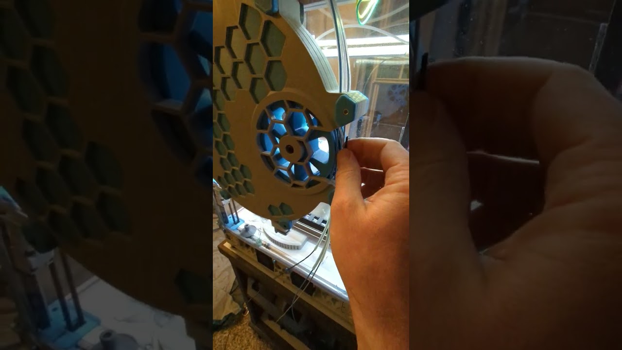
I'll probably have to reprint the wheel edited to be slightly smaller, doesn't roll as freely as it ought to
Probably because it's designed for abs, I just didn't want to deal with large flat prints with my especially warp prone abs
Buffer assembled, manually running filament through it, it seems like it'll work

I think I'll end up modifying the wheel to have holes in it to make it easier to load filament, it's a bit prone to having the tip catch on edges inside the buffer
well that was easy enough, printing the wheel modified with loading holes
The wheel slowly moving is cool to see
how does the wheel behave if you got multiple filaments? doesn't bind?
The other filaments will be loose inside the buffer, so they won't be doing anything to the wheel
The red is what an unused filament is like, the teal is the one currently being pulled, wrapped around the wheel

🤦 got it
haha tbf I didn't understand the point of the wheel in so many different designs until I printed this
well shit
the especially frustrating thing is that I had reused the previous sd card, so going back to the pi3 until a replacement arrives is still going to involve reinstalling everything (the configs at least have automatic backups)
ah screw it, I've had enough for now, going back to the rpi3, it looks like the wifi bandwidth isn't shared with ethernet/usb so I'll have to route through that instead
for the usage there's not much of an issue with network speed or reliability, it keeps printing without network
The camera is my main bandwidth related concern, on the pi3 it seems the wifi bandwidth is separate, while ethernet shares it with usb, so a usb camera first uses the limited usb2 bandwidth to send frames to the pi, then it uses more of that bandwidth to send the frames out
Also thinking about other options, maybe I should just tolerate the 720p@5fps since it's just a monitoring cam anyway lol
I could setup a better camera as its own thing later, I recall seeing examples of people having a separate rpi0w per camera.
@sharp valve depending on space available you can get a security camera and use that, main issue is that most will have RTSP stream and I think browsers cant handle it
(can check with my own cameras)
yeah those could be an option too, I think rtsp works fine in mainsail
I'm fairly sure I've seen that crowsnest supports rtsp streams
Yeah, it does
oh, I can get a camera that uses the fpc connector, that won't use the usb bandwidth, plus probably easier to mount and adjust due to being a bare pcb and using M12 lenses
Reviving the older pi was fortunately less painful than I feared, the pi4 sd card booted fine, and restoring the configs from github went smoothly too
I setup the buffer "properly", with two loops in it to sufficiently buffer for my tube length, seems to add a lot more friction than one loop
Not enough to affect the print, but might affect loading speed a little
Oh I might have the stepper in stealthchop mode, maybe just switching to spreadcycle will provide enough extra torque to not affect loading speed, the rest of the printer noise is usually enough to hide any stepper noise
or maybe I had the thresholds backwards and I've been unintentionally running everything else in stealthchop...
I think both 0 and 9999999-whatever as the threshold values are both ways of disabling it
oh, if that's the case I'm in the clear
looks like I was misremembering anyway and I do have the thresholds set to 0 everywhere
hmm, not finding it clearly stated about 0 as a working disable value. klipper says commenting it out has the same effect, though
dammit
I've only ever dealt with comm issues over cheap BTT USB C cables, the ones that come with the board
I'm using the one that came with the leviathan, but yeah might try swapping the cable
lots of these in dmesg

wuh oh
if HH supports just use it as a secondary extruder during print, I do that with the TR
oh dear
yeah that's what I have setup too
that was the only thing that helped me print with some stubborn PLA that had a lot of friction on the bowden
Hmm, so the canbus adapter on the leviathan shows up, but scanning the bus shows nothing
Going to try power cycling the printer entirely I guess
Nope...
Still nothing on the canbus
Oh wait, nvm, they aren't supposed to show up on the canbus query script when connected with klipper
Oh it's worse, it specifically can't talk to the leviathan mcu
Hmm now it works
That was weird and scary
this error seems to be associated with the 64-bit version of the os

Just started seeing these errors in my syslog, Apr 25 11:34:56 octoprint.local kernel: Apr 25 11:34:56 octoprint.local kernel: WARN::dwc_otg_hcd_urb_dequeue:639: Timed out waiting for FSM NP transfer to complete on 3 Apr 25 11:34:56 octoprint.local kernel: Apr 25 11:34:56 octoprint.local kernel: WARN::dwc_otg_hcd_urb_dequeue:639: Timed out ...
the annoying thing is that rpi imager only shows 64-bit images now and considers 32-bit images to be legacy, even though on rpi 3, 32-bit is iirc faster, and the mainsailos guys also recommend 32-bit
so I guess I'll have to manually download and flash the image
running off a NUC?
nope, my home server 😄
haha I see, I used to do that
just a i5-13400 with 64g ram
running something like proxmox or just a normal linux setup?
I stopped because the can network was a bit finnicky configuration wise with proxmox
on docker containers
ah
but its tricky to setup 😛
in case you're curious using these images https://github.com/mkuf/prind but directory structure differs a little, I want to clean it but no time/patience

print in docker - Deploy a containerized Klipper Stack for your 3D Printer - GitHub - mkuf/prind: print in docker - Deploy a containerized Klipper Stack for your 3D Printer
yeah, I'm generally not a fan of docker due to all the tricky stuff that gets involved haha
I prefer to use lxc's or full VMs
ok sd is setup with the 32bit image again
Hopefully back to printing now, ended up going back to one loop in the buffer, had a slight excess which caused the excess to pop out the top, whereas with one loop it just comes back out the other side
I think I'll experiment with other filaments too before determining if that's just an issue with the buffer
since this is with gold silk pla, which I think is probably rougher and stiffer than most
Looks like 3 loops will just about fit, which results in enough buffer space for that to not happen
Wheel modified with loading holes works great, just stick the filament tip in a hole and rotate the wheel to load, then take the tip out and feed it forward
out of curiosity why
now that you mention it, it does seem hard without that
just had less trouble with them is all, lxcs and VMs end up being simpler to deal with, especially with proxmox's web interface
yeah, as one of the comments on the sternwheeler page said, https://www.youtube.com/shorts/Z2WNvIMlSTY represents the best case for filament loading, normally it often gets caught on random walls in the buffer
I'm on the opposite end, I live in the CLI
I'm typically a cli guy too, except with containers/vms haha
it's a lot easier to just quickly check up on something from a phone via browser than faff about with termux on a touchscreen
true and yet I still do it with JuiceSSH 😆
lol
yeah, similarly the black silk pla won't even reliably roll back with 1 loop
while the normal pla does fine with 3 loops
cutter arm broke again...
At the same point too
Will try reinforcing it and printing in pc

I'd need to redesign the top to make the arm thicker
But also that angle still gets much of the load
recently saw another compatible with sherpa on annex TR channel

Toolhead filament cutter for ERCF / MMU units, mountable below a Sherpa Mini extruder | Download free 3D printable STL models
Ah yeah I've seen that one too, can't recall if there was a reason I chose not to use it
I think I passed on it because it extends past the back, which might interfere with the motor support thing on the sherpa mount
ohh got it, I'm still figuring out if I add one or not, there is one integrated into EVA3 might try to make it myself if I find the time
Yeah same mood now lol
Looks like lumawatt posted their cutter https://www.printables.com/model/742345-e34m1-toolhead-filiment-cutter

A filiment cutter that works with the Zero G Mercury movement system | Download free 3D printable STL models
yep I know of it, there was a mention of doing it a little differently so we don't need to attach with the belt clips
Ah
and I would need to change my homing side
Oh yeah fair point
huh. not wild about it stealing that top right screw hole for the hotend, either
the lever uses a screw, which will eventually loosen from the nut, too.
thinking out loud here rather than open criticism in the EVA3 channel
maybe use the dowel pins from a BMG instead? more compact
same
I'm still in favor of moving the cutter up so it doesn't impact the hotend mount (too much, I have an idea there, too).
The top of the hotend mount is where the marked plane is, for reference

yeah that seems like a reasonable spot
I'm tempted to avoid any fanciness with an actuator arm and just use a stepper to deploy the scalpel when the hotend is in a specific corner
without a shroud, could even leave the hotend largely unmodified and insert it from the front...
yeah, that might be better than a lever on the side, in terms of taking up space for accessories
alternative, just to put it out there, is to add HSI to the marked walls and use those as anchor points

okay, i'm gonna stop spamming your build log and ponder on this, lol 😆
haha I'm interested in designing a cutter too so if you want to think out loud here, go ahead
fair enough 😄
for now just to get this thing up and running again, I'm going to just modify the arm to be a bit stronger
reinforced the part it broke at, maybe I should print it in petg

uhhh my extruder stepper only won't go forward...
hitches when going backwards too
huh, seems fine now
ah interesting, the tension on the extruder arm was too high, and rather than causing other things to slip, it was causing the stepper to struggle
dang, that's not a lot of walls there at the bottom 😦
yep, not a lot of room to work with
can you explain
yep. just leave a gap for the scalpel in the side or front, then when it gets to the front left corner, a motor goes BAM and cuts the filament
it would need to be very precisely positioned, but should do
ehhh not a fan
would allow more build area and require less modification to the toolhead
I get you, but having such precise positioning, and adding another motor is something I'm not a fan of
fair point
oooh
what if the scalpel and spring were integrated, so it was just a button on the side of the toolhead?
like, a spring with a large enough diameter for the scalpel to fit inside
I'm fine with direct actuation without lever, evantis does or did that
had a piece out that activated directly with the blade, needs more force as there's no leverage
@sharp valve let me know if you want me to shut up
ah, yeah, the lever does that have benefit
no, no, go on
do you guys happen to know of any blades that are shaped like a ring? with the blade on the inside, something like that, with an inner diameter of 2mm would probably make designing a cutter much easier, just need any way to move the blade in any direction, vs currently having to consider leaving enough room for a full blade
I can't seem to find anything like that
i'll look and see what turns up
get a washer and sharpen?
haha I don't trust myself to do that
yeah, we'd have the bloody hallway scene out of The Shining if I start sharpening things like that
I do trust myself but at the same time it's a rabbit hole
because I think the material is not heat treated so it's too soft, and then I would go like heat treat, what if I made my own, and suddenly I got a forge and hammers etc and I'm making my own blades
lol
home dude forging mjolnir over here in his garage...
last thing I need is another expensive hobby
I already got into too many only to be left with a ton of tools and a ton of stuck money
oh!
how well does cutting wire work?
I have zero experience with it, so idk if it's realistic to expect to cut filament by tightening a loop of it around
something like https://www.amazon.com/dp/B08HHH7T2F?ref=emc_s_m_5_i_n&th=1

SUBRILLI TRADING CO., LTD is a professional supplier of Abrasive tool with high quality products, excellent service and a good reputation, we have won great support from customers around the world. Thus, our company scale has expanded.All products shown at real prices and original pictures/video,...
hmm, I guess it would be difficult to maintain it in a loop though
agreed on that
maybe a different style of cutting blade/scalpel?
filametrix uses a strqaight blade, the one I'm using uses one like this

oh shit
there's an 0.8mm gap between the hotend mount and front
hobby blades are just over 0.5mm thick
something like this would do very well

ooh
if a #11 or #24 hobby blade will work at that location, that leaves the actuation mechanism
what if we can make the blade externally mounted and actuate it using the toolhead instead of a separate stepper?
sooo what if the blade is mounted to the X axis
and rotates from "safe" (aimed backwards) to "ready" (aimed to the right at the toolhead)
yeah that would be fine I think
have a release latch on the x joint that the toolhead bumps into. toolhead backs off on the x axis so the blade completely deploys to ready position. toolhead hits the nasty bits, then backs off again. then the gantry moves forwards until it hits something that locks the blade back into the safe position.
no external stepper, but blade is externally mounted and actuated
sounds complex
could be, yeah. depends on how it's done, really
move wise will be
one of the reasons for a cutter is to swap filament faster as well
is the switch from safe to ready necessary?
if you have many moves to cut takes time
well it can be stationary but it will always be in a position where you can hit it with toolhead
oh I think I misunderstood, yeag that explains the need for the safe position
for that reason the lever can be somewhat safer, if like you it's in the opposite corner of homing it will be hard to hit accidentally
and even if you do you just cut the filament
with a blade protruding its a lot longer
If we dropped the toolhead mounting idea entirely, instead, we know the length from the mmu to the nozzle, so mmu mounted cutter and a postprocessing script which puts the cutting point that length before the actual swap point
Then just a small purge to allow the color to fully settle
Although I guess that's even more complicated lol
what about the cut tips? how to extract them?
ohhh, i see about the cut and swap points being diff
Usually we just let the tips get purged out
Yeah
Maybe the cutter could be something generic that just takes an entry and exit bowden tube, so it can go on any mmu
Although I guess that might still cause trouble for retracting the filament, eg when finishing print
safe/cutting


what if we attach it to a magnet
it need to go in 4mm. the only force resisting it is the filament, so once it's cut, we can pull it out very easily with a magnet
mount another magnet on the x joint
you mean kind of like a sideways klicky? having the blade be picked up when needed? or just using the magnets to move it back and forth?
just using the magnets to pull it back out
a magnet on the end of the blade that the x joint attracts to. ram into it to cut, then pull it out and the magnet pulls it with.
yeah, that could work, maybe instead of having magnets on the x joint to pull it out, there could be repulsive magnets on the toolhead to push it out
that would keep the blade from floating out of position, too and cutting the filament
yep
sick, this could work very well
yeah, this seems like a nice small design that meets most or all requirements
and dead simple, to boot
yep, no springs to worry about ordering lol
I think the #24 blade is going to work better. or a straight on, maybe.
a straight blade feels like would be better
like #4 blades?
I think that's what the stealthburner cutter uses
or #16, shorter, and would be able to retain itself due to its shape
#17 hobby knife

I ordered this pack, so I'll have plenty to experiment with. I lost my hobby knife and need a new one, anyway. 😆
haha nice, I just printed a handle for the lifetime's supply of #11 blades I got
3d printing to the rescue
don't even bother taking the blades out of the broken cutter arms because I'm not getting through 100 blades anyway lol
I consider that fair, lol
hmm. so I don't want the magnets to actually touch, just resist
klicky magnets should do
aaa today's the day of extruder troubles, stepper wouldn't move again, noticed it started moving fine as soon as I started to take it off the extruder, toolhead sensor wire had gotten pulled under the extruder into the big gear 😬
oh shit
luckily didn't manage to break anything
ugh

nothing obvious about the cause from any log
looking through the log in more detail, it was indeed the toolhead
hmmm no maybe I misread
looking at load plots for all the mcus, bandwidth and load were all pretty low, but buffer did fill up
I'd wonder if it was microsteps, but this was during a purge move
I guess I'll just restart for now
Ryan @ Annex is working on something generic
6x3
I think 11 will be better
ooooh
rpi cam kinda setup, still need to pick out a case and mount for it, but software wise seems to be working now
interestingly, a 1m long cable was not producing a reliable signal with the 'modern' camera stack, but seems to be working fine with the legacy one
But the newer stack is needed for hardware accelerated h264
I guess that's probably why having a pi zero just for a camera is a thing, no need for a long ribbon cable
long ribbon kinda sucks
Yeah that too
😬

Was finally getting around to swapping out the belts for the slightly longer ones for eva3 to properly hold them, noticed the front falling apart, so I guess time to put everything aside to slowly print the replacement
Really should reassemble the ender 3 just in case...
hmm, the belts are still slipping
oh shit, what happened?
dunno, just noticed the front falling apart when I took the hotend off to change the belts, I'm guessing the abs I used just wasn't very good
I guess I can hold the belts with zipties enough to print the replacement
yeah, prolly will work
ok seems to be printing
slowed it all down and used a pla belt holder (not that it seemed to do any better at holding the belt)
lowered bed temp down to 60C and used bed glue
whew, slight warping at the corners, but the replacement will work!
looks like the reprinted clamps might fix the belt slipping too
what was the orientation you printed it
The "default" orientation

I suppose it might be useful to reprint with supports and at an angle
for some reason though it was supposed to be upside down
oh?
cracking that way was confusing me because I thought the orientation was different
I'm confusing with the hotend mount
maybe with the normal front? with the pis one this feels like the most natural orientation
ah
ah could be the normal one
swapped the part out, going to try a stress test running input shaper calibration
decent enough result
The damage 

Just barely held together by one layer on the bottom there
And from the other side

Based on the marks on the screw holes, I think I must've overtightened them
Finally, camera mount printed and assembled

Tried switching back to the "modern" camera stack with the hardware accelerated encoding etc, so far seems to be working
~1.5MB/s for 1080p@30, so should leave enough bandwidth for everything else
Back to prototyping for the purge system tomorrow I think
I think it's the hotend mount you're confusing. I do that a lot, too.
btw, blades came. dunno when I'll get to it, but I'm thinking on it still
and after a night, back to timing out
I have two main options I guess, I can get a pi zero for the camera specifically
Or I can move the rpi to the top near the camera, where I'd have it powered by the skr pico driving the ercf, wired into a canbus transceiver to talk to the leviathan and toolhead
Ok I think what I'm going to do is make panel clips to start cutting and mounting side panels on the printer, as part of that I'll add a place to mount an skr pico and rpi
For the back I think I'm going to enclose the part below the steppers with a panel, and print the part for enclosing the stepper area
Not sure about the front yet
maybe I can just print a bunch of these for mounting the panels https://www.printables.com/model/233180-voron-quick-panel-clip

Quick panel clip for Voron 2020 extrusions and 3mm panels | Download free 3D printable STL models
maybe extend them to ~6mm to line the panels with foam tape
and vhb tape + clamp mounted hinges for the front panels? 🤔
I fully expected hand cutting the panels to be a nightmare, but turned out surprisingly easy
Oh, it isn't going to be as simple as using these clips to hold the panels
The rail carriage slightly extends past the edge
No avoiding custom panel mount parts I guess
If I space them off the frame, I'll have to have some way to seal the gap, I could do foam tape, but left uncovered it's not going to look very good at the top, so maybe just printed parts everywhere...
I guess in that case a top hat + flush bottom panels approach will be more efficient
Ah yeah, I have to do it for the back anyway, so it'd end up being a similar piece on the sides
Moved rpi to the side and switched over the ercf controller to an skr pico, only to realize that I don't have a convenient way to power the pi then lol, tried forking off from the canbus transceiver (which would otherwise be for powering the pi) but doesn't seem to provide a stable supply
So now I think I'm going to move the rpi back to the leviathan, keep the skr pico for the ercf, and ordered a pair of boards which allow carrying the camera signal over an hdmi cable, which apparently is more reliable than a long ribbon
Come to think of it, I could've just run a usb cable down to the leviathan lol
But eh, I'll try out the hdmi extender thing
Doing a test print with this little tidbit right now. 4.8mm of travel is all I need from the blade.


hmmm looking good
camera seems stable on a shorter cable, hopefully the hdmi extender works, will have to setup proper lighting to get good image quality with the low exposure times I've configured though

fisheye lens just arrived too
that's niiice
the fisheye lens is even nicer

I believe kids these days call that "lit"
Oh no, might've unintentionally let out the magic smoke from the ercf encoder
Yep, 0 counts, it's dead
Led won't flash as filament moves either
ohhhh does that work with any cam?
well crap
I got an rpi cam with an M12 lens socket, so I was able to just order an M12 fisheye lens to use instead of the standard lens
I had the wiring right, but colors wrong, so without properly checking the pcb, I swapped around the gnd and vin wires when moving over to the skr pico
Smell of burning electronics shortly after
not fun, I made magic smoke when moved from dual pico to skrat, put 24v on can data lines
killed the can transceiver on the thr
and now I know why the 4pin fans on the SKRat come with voltage set to 5v, while all others are at 24
because if I didn't try to be a smart ass and change them (for no reason) I wouldn't have burnt it
I'm not sure I follow
so my issue was that I plugged on the fan port instead of the can port
they're side by side
the fans have selectable voltage, the 4 pin ones had the selection jumpers set to 5v
like out of the box, but I decided to change them
tell me about it
entered a giveaway, won panels for a RR VCore, I don't have a VCore...
ehhh.....
they had mechanical kit with 30% discount, I was going to order but just went to see no more discount
so I'll delay
Fair enough
I managed to stave off overspending at fabreeko by finding the encoder on Amazon
I can't really spend the money right now, as it stands might self source if it's cheaper (with the 30% was not)
Yeah similarly I really need to be cutting back on spending, previously it was big expensive parts so it was easy to track, but now it's lots of small purchases that are adding up
latest was an integrated gear for the sherpa
should arrive this week and I still need to cad the sherpa for fixed idler+ecas+sensor
Oh yeah, I'm interested in hearing how that goes, I'm running a brass reduction gear from mellow with a cheap bmg clone kit for the rest, works fine, but those integrated gears look cool
Will let you know
On the slightly disappointing side, camera extender got delayed to tomorrow due to snow storm, on the bright side, ercf encoder got pulled forward to arriving tomorrow also
what if the cutter mounts where the ADXL goes?
you wouldn't be able to use a shroud, but it allows cutting from the front, which requires no modification to anything
my open question is how to keep the PTFE tube from moving around and bumping into the cutter. filametrix uses modified heatset inserts.
Putting it in place of the adxl would be fine imo, I haven't had trouble with the ptfe moving around even without inserts
front is fine if I find a way to bump on it, my front extrusion is dropped
don't forget those who don't have one (like beta frame)
I'm thinking of leaving it on the x joint, but have it sticking out the front, maybe? I dunno
could just have an arm on the side which sticks out for hitting the front against
the boards to carry the signal over hdmi are interesting, signal carries fine over a long cable now, the signal is probably also 'cleaner' since while perceptually the image seems less noisy, the peak bandwidth usage also went down from ~1.3MB/s to 800KB/s, also a little weird though since I wouldn't expect this kind of thing from a digital connection
encoder replaced! seems to work, it's a slightly different design, having two leds which alternate when the wheel moves compared to the standard one's single flashing led
it's "known" to have issues at 3.3v due to too high of a voltage drop, but luckily I'm driving it at 5v
Pi moved back to leviathan, camera still working fine, so looks like the hdmi cable thing is working
data compression?
more though on front cutting, won't let me add shroud with leds
Add a cutout to the shroud for the lever 🧐
hmm could work
Yeah, this is with an h.264 stream I think, so the less noisy an image is, the better the compression, so improved signal quality = lower streaming bandwidth
I just compromised by hanging some LEDs off a fan grill mount
back to printing, but I clearly need a sturdier camera arm, this thing is too flimsy

camera had too much coffee
lol
aaand the auto-z issues continue
switched back to unklicky... working for current print
for now my working theory is that while this clone switch was great early on, it wore out quickly
Also looks like one other concern with the sternwheeler design panned out, the loop at the edge of the wheel slid off
I guess maybe next is to try a rewinder and see if the recommendation against it is justified
https://www.thingiverse.com/thing:3739793 thinking of trying this one
Filament load/unload issues? MMU2 taking too much space? Not with this Sisyphus Auto-Rewind spool holder! It keeps filament on the spool during unloading, up to almost three revolutions.
Use two curved nuts to attach the spool to the roller. Put roller on stand. Insert filament in extruder/MMU2. That's all!
A filament tube can be installed from ...
although maybe modifying the wheel could fix the issue
otoh I had been thinking about eventually switching to full ercf v2 with the cottontail buffer...
I guess for starters I'll just reduce the number of loops I use
@sharp valve that one has one issue
the sisyphus you mean?
I'm guessing the part to grip the spool doesn't actually work that well?
nope it's the length limit
looks quite short
for near empty spools might be worse
Ah that's a good point
hold on
https://www.thingiverse.com/thing:3516858
https://github.com/EtteGit/EnragedRabbitProject/tree/main/Carrot_Patch
REPREWIND - AUTO-REWIND SPOOL HOLDER FOR THE REPBOX
This is a remix of the Universal Auto-Rewind spool holder. This remix is designed to be used with the Repbox Filament Management System and can hold 5 spools with rewinders inside the Repbox.
This was a unique undertaking. We had to thin down the entire assembly, while maintaining operability...

Contribute to EtteGit/EnragedRabbitProject development by creating an account on GitHub.
these were my options
a lot of new stuff now so I'm unsure
for ERCP
#cad message
I made these never tested
I've been avoiding ercp since I've seen it described as "a waste of filament" lol
reprewind is on my list of options to look into more carefully
never saw that
I think I'll try reprinting and reassembling unklicky to eliminate the extra play my pin has
aaand the filament sliding off the edge issue isn't just limited to the edge lanes... so yeah I guess I'm going to have to try out other buffer designs
oof that sucks
oh I wonder if the 'jerkiness' for passive rewinders has to do with what happens at the end of the rewind
if the rewinder has too much inertia, it's just going to yank the tip out of the mmu
because at that point nothing's really gripping it
oh?
didn't try it but it's promising
on ercf the gates just use a bit of friction from lightly pressing the filament against an m4 nut to hold the filament tip when not engaged
so relatively easy to have it pop out
#1073213131964293180 message
not sure how much force this actually has
but I did like the concept
oh yeah that's a neat idea
Melt zone extender comes in today, I just grabbed it off amazon for the fast shipping, not the cht version, but will do well enough for increasing the toolhead clearance enough to not have to watch out for hitting the sexbolt on larger prints
and it does increase flow
yeah, that is a nice to have
Will that work with EVA 3? the melt zone extender
I'm increasingly of the opinion that ducts should be adjustable and come with a tool to ensure the proper offset from the nozzle.
It would just be going from rapido hf to uhf I think, so it should work, at the moment I intend to just see if it'll do fine with the hf duct, but if not I'll just print the uhf duct
That adds its own issues in terms of duct rigidity/strength
hehe, also increasingly of the opinion that toolheads should have an Alu "frame" to add rigidity
Oooh, camera preview doesn't work due to my using cloudflare tunnels for local network access, but even just printer status (and supposedly notifications) on watch is cool

Hahaha
that is excellent!
yes have one
It's a lot of tradeoffs, wouldn't want the toolhead to be so strong it breaks other stuff if something goes extremely wrong, but also not so weak that it breaks when something goes slightly wrong
are we talking about the rapido UHF/HF switch? because I'd feel dumb if that's the case.
Octoapp for the curious
It's not explicitly the same part I think, but it does the same thing
lol, my bad then
yes
https://a.co/d/6yQSeX2 I think it's resold from the one trianglelabs sells

Package: 1pc plated copper adapter
huh, nice
mine is mellow
also whats this
I want that for my watch

The most advanced OctoPrint and Klipper app with many features and updates!
I've wanted print notifications on my watch since forever, was going to set them up through homeassistant but kept putting that off
just octoprint? or mainsail too
Mainsail too
yeah I did those with HA
but having live camera is nice
progress I have on a template tile
Has a plugin you can install which handles some other stuff like camera streaming (it has mjpeg support, but rtc support is coming soon ™️ )
Camera streaming if you aren't running an mjpeg stream
Ah yeah, then it'll do for your purposes
rtc need ro put it through frigate if I want rtc or anything else
Ah
speaking of which I should set up continuous recording on frigate for it and enable disable with HA, at least I'd have a better view of some failures and causes
ohh taking note of that
Oh yeah that's a great idea

Hmm I'm guessing the uhf sock is different?
Ah yep
Sockless should do fine for now I guess
ohh yeah
I like those leds
or is it flash?
Small led strip mounted hanging off the front fan
The leds look blue on all cameras for some reason, even though they're set to white and the white balance seems otherwise fine

Ah looks like it'll be a good idea to get the proper sock, it's struggling to maintain 260c at even 50% fan speed
Or maybe just turn down max fan speed?
sock
well, time to risk my wallet at febreeko or west3d then
https://www.fabreeko.com/collections/mods/products/nevermore-scorch-filtration-media-bag?variant=44599480156415 oh this is interesting

What it is: Nevermore Scorch is an advanced air filtration media, designed for the unique demands of 3D printer chambers, especially at elevated temperatures. Traditional carbon filters become less effective above 50°C and are significantly less efficient above 60°C. Nevermore Scorch adds the heat resistance regular c
but will save for the next batch of carbon, still have a few months of supply
tried just reprinting regular unklicky, but pin still didn't seem to slide smoothly, now printing out the bfp-hs version
Assembled, breaking it in with a 500 sample accuracy test, looking good so far
0.005mm variation so far, essentially noise
0.011 overall, still good enough

uhhhhhh

Probably not a real bed issue but some other issue related to the frame
Could also sand it a bit
That's what I did and then broke it in like normal
That's a high lift all on the left. Maybe something is up with your X beam?
The issue with the first one I made was that I oversanded it and it had too much play, I felt like the right amount of sanding for the normal unklicky would be tricky to figure out, the bfp version still needed a little sanding, but was much more forgiving since the pin really can't tilt in it
Yep, I need to get around to trying to understand in more detail what's going on with that edge
Oh yeah that's good with the bfp version
What brand rails do you have?
Various random chinese ones, replacing them with known good brands is on the list ™️
I had an issue on my machine with cheap rails that the suggested M3 bolts to mount the X idler mount to the mgn12h were a tad to long, they bottomed out and allowed the whole X beam not to be flat on the carriages
So I had to add a washer to the bolts
I know it's only specific, but worth a check!
It caused my bed readings to be off on 1 side particularly
Yeah that's a good suggestion, will check for sure, now that you mention it, I did start having issues with using all 4 corners for z tilt after I had to rebuild the toolhead, so what you're saying would fit
Yeah definitely check those X idler mounts are flat on the carriage!
And check for any wiggles
I know my x axis seems to allow for a little toolhead wiggle, haven't nailed down if it's the bearing block itself that's slightly loose fitting
But that rail especially is one I intend to swap out as soon as I get my parts spending back under control 😅
moving the printer and reseating the x rail helped a little

I'll try reseating the other rails too (just loosening the screws slightly and letting the carriage readjust the rail placement)
hmm that didn't help
probably actually the rail or frame then
Nice part though is that this probe is so far seeming very consistent
yep, moving the printer again reduced the issue slightly more, so I think it really is a frame issue
after over a year, finally time to get to one of the projects I got a 3d printer for in the first place
This is a Remix of Balazar's Open Alpha with bass ports. This version contains a strengthened and modified output jack that allows for the use of 2.5 and 3.5mm connectors instead of the standard Hirose connector. The Hirose connectors can be hard to source and the standard the 2.5mm connector an easy to find and more versatile substitute.
The c...
did them in pla back then (since pvb hadn't worked out too well), but have wanted to redo them nicely in acetone polished abs for a while
Also, for now I have stumbled across a different filament buffering solution
So my spools are held on tush holders

Noticed that with ptfe running towards the spool, what happens to excess filament is that it just loosely goes around the spool
Meh, still warped on cooling down
I guess I'll wait to get ASA or reprint in a less warp prone abs
Man, timer too close error killed a nearly done overnight print
that sucks a lot
agreed. what causes that error, anyway? I've heard of it.
usually high CPU load on host
@sharp valve what distro you have installed on the pi
Mainsailos
It looks like camera-streamer decided to eat 70% of the cpu 😬
I'm just going to get a separate pi to handle the camera, screw this shit
Then if it does something stupid at least it doesn't bring down the entire print with it
shiet
dafuq!
Almost kneejerk bought another rpi4 but I think I'll try running the streaming off an x86 board I have laying around
Seems to be somewhere between the 3b and 4 in performance
Although alternatively I could just slide my server over a little and drive the camera off that
Just totally eliminate any performance concerns
just run entire klipper off server
I avoid that since I don't want to have printing tied to whatever I might do on the server
switching over to haos instead of running homeassistant in lxc, hoping to set up camera streaming through it
oh wow, I hate this
haos?
yep
just got really pissed off by the terrible documentation and unnecessarily customized os
haha
by terrible documentation, I mostly mean when running slightly differently from the simple path
I have lost count of the number of people I saw having issues with haos and either losing data or taking days to get it working again
yep, and it looks like the default response from the devs is hostility
well, more like passive aggressiveness?
some of them yeah, the modbus one broke a ton of integrations because his understanding of the protocol is different than most people including some HW manufacturers
electricity meters being an example
oof
huge latency, but at least got a stream working
This is still not a satisfying solution, but it'll work
wait really?
you're better getting it in pure docker then
not too sure, but that seemed to be an explanation I stumbled across for why it's so annoyingly whittled down in terms of what you would expect from a regular linux system
if you decide to go that route (pure docker) and have any questions me know been running mine like that for a few years
ah yeah, not doing that for now, I tend to have nothing but trouble with docker lol
and I've already dealt with enough trouble today 😅
oh not rushing you, I just mean whenever/if you feel like it
This was a pain to setup, but got esphome hooked in for an ledstrip

Ordered a 15A buck converter to power more extensive lighting (plus, having a bunch of 5v juice is always nice)
Took a break from the printer, back to it now, I think I'll start reprinting the bentobox upgraded to v2 with 5015 blowers in pull config
I ordered the gdstime blowers, apparently much louder, but also much higher static pressure
I want to be able to mount it such that it's pulling air from where the nozzle is, to be more effective at catching the fumes (not that it's doing a bad job right now) and to better contribute to heating the chamber
Oooh the intrgrated gears are here already
noice
please show before and after
Ah yeah I guess I might as well do a before and after print
ok found the test model off https://mihaidesigns.com/inconsistent-extrusion/
printing
same I used
ooh, good link
This is the best picture I managed to get

Barely visible, so I guess there isn't a lot of room for improvement already, I wonder if the main brass gear is part of why

Integrated gear is much lighter
Gears swapped, reprinting
Probably should've retuned the esteps but eh, started the print already
I did not retune mine 😅
light must come from above
Ooh that worked great

(Prior to change)
Interesting that it isn't on the first few layers
Is it better or just more consistent?
The pattern that's visible here is basically the same, but if I look at a grazing angle, I can see a very slight reduction in variation
Not enough that I'd say it's meaningfully better
Trying to show what I mean, this is the old print

This is the new one

Basically the change is so minor that it probably wouldn't have been worth it if I didn't already want another set of gears for a second printer
Yeah
Did you print at 20mm/s as the instructions said? Or typical printing speeds?
The other surface artifacts are probably down to the motion system, I've been growing increasingly suspicious that my X rail is not very good
20 thick lines and fat layers
Ah ok, same setup here
So yeah, interesting that we had such a big difference in outcomes
ughhhhh

Maybe I'll have to get/make a u2c after all, read that sometimes that eliminates these errors by essentially putting the canbus processing on a dedicated mcu
I have some rp2040s and a uart to can transceiver, so hopefully I can just make one
Tried making the stepper mesh slightly more loosely with the hob gear, seems to have made things worse

yep, 20mm/s, they weren't forming consistent lines so I figured it isn't the belts, but I can reduce the tension and try again anyway
Had this happen again, also just noticed it says mmu, not mcu, so it isn't canbus, I'll try replacing the usb cable I guess
on this one you can see the pattern kinda like ressonance but looks belt teeth size
I tried loosening belt tension mid print to compare, no change, it looks that way but doesn't seem to be belt tension
Large banding is from me messing with belt tension

Also not on y-axis, so it's probably something else in the motion path

My main theory is the x rail, but it could also be one of the bearings or idlers I guess
toothed idlers are always my first suspect on x axis-only issues
one way to test it: print at a 45 degree angle
Oh good point, I'll do that
that's my only good idea for the day. time to call it quits, I guess. 😆
Lol
also, another interesting thing, so I had the camera stretching its cable to the max to just barely point at the bed while plugged into the server, this had like 3s lag on the feed
extenders came in today and the lag went away too
45 degree angle

there's still some
but does look better
I wonder if the silk filament has influence
Oh yeah, would be worth trying with other filament, I was using silk because it tends to make flaws a lot more visible
Printing in white pla, having a much harder time making out this pattern while printing
Not at all visible in white


Well, looking very closely, I can just barely make out the same "noise"
probably
part of why I printed in that gold filament was that I really didn't like it, was finding it to be too tacky of a color
got like 9kg of pla laying around I need to churn through, but all I end up printing is functional stuff in abs lol
https://a.aliexpress.com/_mKliKKK I wonder how well this would work for auto-z
Ah looks like the issue with it is that the sensitivity seems to need calibration and can be temperature dependent
thats not even auto z, that's nozzle probing which is great IF it's reliable
Well yeah, but probing with nozzle would have the same overall effect of eliminating most of the z offset adjustment work, just needing the very small offset of the disk itself
are piezos affected by heat?
I recall reading that they aren't supposed to be, but some of the reviews of these kits (at least the clone ones) seem to suggest otherwise
idk
- Piezoelectric disks suffer loose sensitivity with increasing temperature, this is particularly evident in "no-name" units where a maximum usable temperature of 50ºC or 60ºC is the maximum working temperature.

- PZT suffers from a pyro-electric effect which causes a voltage to be generated with changing temperature. If the low end cutoff of the conditioning electronics is too low then changing temperature may be interpreted as a nozzle contact.
hmmmmm
says later they work, but require thermal isolation from the bed
still, not the home run I'd hoped
same
https://reprap.org/wiki/Piezo-electric_sensors this page seems to go into a lot more detail, says that above hotend is a bit easier since the temperature differences are a lot lower
at $15 maybe it won't really hurt me to get the kit and try
0.01mm accuracy is pretty low compared to what we're used to, though
well, if it's consistent with less maintenance, that'll make up for the accuracy
fair point
I have a set of 6x3 magnets coming in today to try remaking my unklicky, I glued in the magnets, but I noticed that they're supposed to be flush with the body and I don't want to risk taking it apart until I have a perfect fit
they aren't quite flush. I think those klicky holes are lik 2.6mm deep and the magnets 2.8 or so
ah I see
hmm, I guess I'll have to do more testing then to figure out why the z offset is still drifting then
if the magnets have varying thicknesses or are not evenly installed, you can get a wobble when the klicky engages
oooh yeah that's a good point, will check for that
hmm, doing some testing, the issue seems to be ~0.02mm variation/drift in probing, which compounds into ~0.05mm variation in the z offset
probe slower
yeah was just typing that haha
I setup two probing speeds, a fast probe first to get closer (this sample is discarded, had set this to be at 50mm/s, but that was loud and scary so dialed back to 20), then a 1mm retract and probing at 2mm/s for each probe sample
does that improve?
seems to help, ran a couple of probing operations with ~0.005mm variation in z offset
but best test will be to wait a few minutes and try again
(docking and attaching for each test, so also accounting for any variation that might introduce)
need to have a look

Klipper plugin for self-calibrating z-offset. Contribute to protoloft/klipper_z_calibration development by creating an account on GitHub.
the "probing_second_speed" and "probing_first_fast" options
ohh never noticed them
same, didn't even know that two speeds was an option for the z endstop (looks like it's an option for all endstops)
might change that my homing speed was quite high and had to drop it
my homing speeds haven't given me much trouble, but yeah this might let me be a bit more aggressive with them, especially for the retract speed
would be nice if we could have this kind of probing for everything else, but doesn't seem like that's an option
I suppose bed meshes and z tilt can afford to be slightly faster since they don't have compounding errors
1mm/s for z offset, 2mm/s for tilt and mesh
ok yeah, this seems to be a lot better, ~0.01mm variation in z offset between attempts
z tilt can also handle 4 corners again, I wonder if the issue previously with that was that the probe was hitting the bed so hard as to tilt the unsupported parts of the bed slightly (~0.05mm)
printing the uhf kraken duct after a long pla print last night turned out to have curling on overhangs, not enough to ruin the print fortunately
ugh spoke too soon

-_- at least it isn't the mmu this time
looks like IO wait
Ah maybe
because process time is low, while load is high
hmm yeah that makes sense
so the issue might be with the sd card
I don't think I have any spare cards laying around...
going to try turning swap off and tracking disk write and read rates
maybe should setup log2ram

but even then it's not really hitting the sdcard that hard
I have a good 5v source now, so maybe I can try hooking up an x86 board I have, it's faster and has on board flash for the OS, main issue is just that it's larger and I'm not too confident in its stability either
I could also just give in and use the server...
@sharp valve can you stop journald?
not that the IO is that much but with systemd stuff you never know
Over a print it wrote ~25MB, not much but still seems excessive
This time printed fine, so it's just extremely intermittent whatever it is
At this point I have zero trust in this rpi in general lol
Hesitant to get another too after the one I did get was DOA
Oooh the print came out flawless, always so satisfying, especially with gf/cf-abs
so yeah, that on its own resolves the issue with the fan cooling down the heater at 100% lol, although I was going to need to switch anyway even if I put on a sock
aaand the cutter arm snapped again
this time completely broke off -_-
not going to print another one, this design is clearly flawed
Looks like the ercf mounted cutter has had a few more revisions so maybe I'll try that again
Ah nope, that dropped support for ercf v1
So I guess I can either try to design something based on everything we've discussed, or try printing one of the evantis/micromantis variants
https://www.printables.com/model/755789-xol-filament-cutter/ this one seems to be a more reinforced version of the same cutter

Filament cutter for Xol toolhead, remixed. | Download free 3D printable STL models
This is probably another source of the z offset inconsistencies on the hf duct...

Bought a blade kit, will see what fits best, probably just the same as jon's prototype, trying to figure out how it might be prevented from falling out though
Filametrix expects you to cut and shorten the blade, which seems dangerous
To simplify my own testing, I think I'll have it be a mod to the extruder mounting plate, but kept simple enough that it could be made into a mod for the front piece
For the actual cutting and moving the blade back out of the way, I think we could just have a small piece that goes on the blade handle and holds a magnet, then corresponding magnet on the pusher block
Link to easily go back to the design #1128402326823125122 message
Based on those blade dimensions, I guess it'd just need a slight extended bit there to hold the blade in at the part where the width changes
Actually maybe a scissor type mechanism from the side can work out with #11 blades
#11 and #17 were the ones that seemed most appropriate to me. I'm still convinced that that 0.8mm built-in between the hotend mount and Front is a perfect space for the cutter.


