#archived-shaders
1 messages · Page 177 of 1
@grand jolt But I think derivatives is the solution there. That's what's used by the shader to determine what mip level gets used.
Sounds complicated 😓
fwidth is pretty simple to use actually. You give it any scalar variable in the fragment shader (could be world position or uv or distance from camera, whatever) and it will tell you how different the value is in neighboring fragments
So in your case, if you give it UV, the value you get back for the pixels closer to the camera is going to be much smaller than the value of the pixels further away from the camera
Then you can pick some multiplier to add to that and use that to drive a lerp between what color the pixel is supposed to be and a blend between the two colors
Which is like a cheap blur in your case.
TLDR; fwidth can tell you how much you should blur the current fragment
Hi guys! I was wondering if there was a way to fade in and out objects in URP? I looked online and it seems like people recommend changing the MeshRenderer's alpha value, but it seems like there is no color property in URP's MeshRenderer. I'd appreciate any help.
The default color property name in URP was changed to _BaseColor instead of _Color
Probably lol
thanks a lot
Wait just making sure, if i were to change that _BaseColor property, would it work outside the editor?
in builds?
Sure
I have a mesh and I'm trying to color its surface(everything that points directly upwards in object space) with a different color. I thought that this would work but the bottom is affected as well. I'm guessing it has to do with me having a misunderstanding about how normals work. Could somebody clarify?
Looks like Comparison doesn't allow Vector3s as the yellow connections are being converted to blue/cyan ones
Aw shit good spot
Should probably Split and take the Y value only
Thank you
I would use a Dot node instead. Then you can pick your own threshold of what counts as pointing up
And you might be more interested in the world normal than the object normal
I can't imagine many normals being exactly equal to 0,1,0
Top parts are flattened but yeah I'm sure I could be running into issues
Yeah, I wouldn't use equal. Could test if the Y is greater than 0.9 or something
I'm looking into dot product
If you get the dot product of (0,1,0) and the normal, the value you get back will be 1 if they are equal, 0 if they are orthogonal and -1 if they are opposite
And everything in-between is in-between
Think so, yea
Dot product is used for many things in math, it just happens to have this property of being able to compare vectors.
Thank you @low lichen & @regal stag
Thank you for your suggestion earlier @regal stag regarding the RenderFeature, I managed to get it working finally!
btw, are you and Cyanilux @ twitter the same guy? In that case I learned a lot from your github repo too.

Nice! Yeah that's me, glad it helped
Heya I have a very important issue regarding billboarded sprites in VR. I have a plane with a shader that is billboarded to always face the camera, and it works just fine
However, whenever the camera rolls, the billboard will squish itself
This is a massive issue because I am making this shader for VR, and people always tilt their heads in VR
Here's an example of what I mean
No camera roll/tilt:
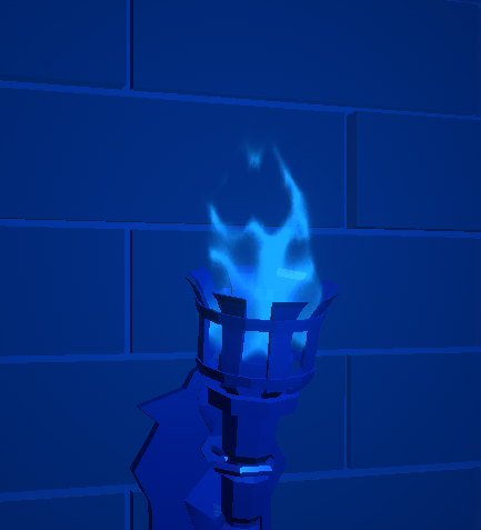
Camera roll/tilt:
I essentially need the billboard to ignore the camera's Z rotation
but I am unsure on how to accomplish this in the shader, I am using Amplify as well (which is very similar to shaderforge)
Any help would be massively appreciated
Any game that has billboarded grass or vegetation should also have this issue, so this is has to be a very common problem
Has anyone found a way to set the stencil buffer through shader graph? Could I use the custom function node for that?
I don't think a custom function would work. The stencil is part of the Shaderlab syntax, not hlsl
do you need it for URP or HDRP?
URP
You can override stencil values using the RenderObjects feature on the Forward Renderer if you are using URP
It only really filters per-layer though
yeah that's what I'm currently experiencing
It seems like this is the probably the best way to achieve a cross section effect:
I· Duplicate our model in the scene and apply a material with the first shader on first model and apply a material with the second shader on the second one. Make sure the two game objects have the same position and rotation.
II· Control the cross sectioning parameters (Plane position and normal) of two shaders through code, to do that we can create a quad/plane object in the scene and attach a simple script on it that map the plane normal and position to our two materials. The script might look like this:
using System.Collections;
using System.Collections.Generic;
using UnityEngine;

//[ExecuteInEditMode]
public class CrossSectionPlane : MonoBehaviour
{
    public Material mat1, mat2;
    void Update()
    {
        mat1.SetVector("_PlanePosition", transform.position);
        mat1.SetVector("_PlaneNormal", transform.forward);
        mat2.SetVector("_PlanePosition", transform.position);
        mat2.SetVector("_PlaneNormal", transform.forward);
    }
}
source: https://codeburst.io/unity-cross-section-shader-using-shader-graph-31c3fed0fa4f
I wish I could avoid having duplicate objects in the scene
I feel like the example they've used could just be combined into one shader using the plane as a mask, instead of clipping.
Oh but the top part is transparent I guess
Yeah I keep feeling like there's a way to combine the two methods.
Up until now I have been following this write-up that utilizes the render objects renderer feature based on layers: https://theslidefactory.com/see-through-objects-with-stencil-buffers-using-unity-urp/
You wouldn't need duplicate objects though, you can actually just assign multiple materials to the same Mesh Renderer. Or use the RenderObjects feature with an Override Material.
No one knows the solution to my problem? 😭
@grand jolt what does your graph look like?
One sec lemme load it
@grand jolt in the shader when you get the plane to face the camera you should split that and ignore the Z axes
yeah I was gonna suggest split node
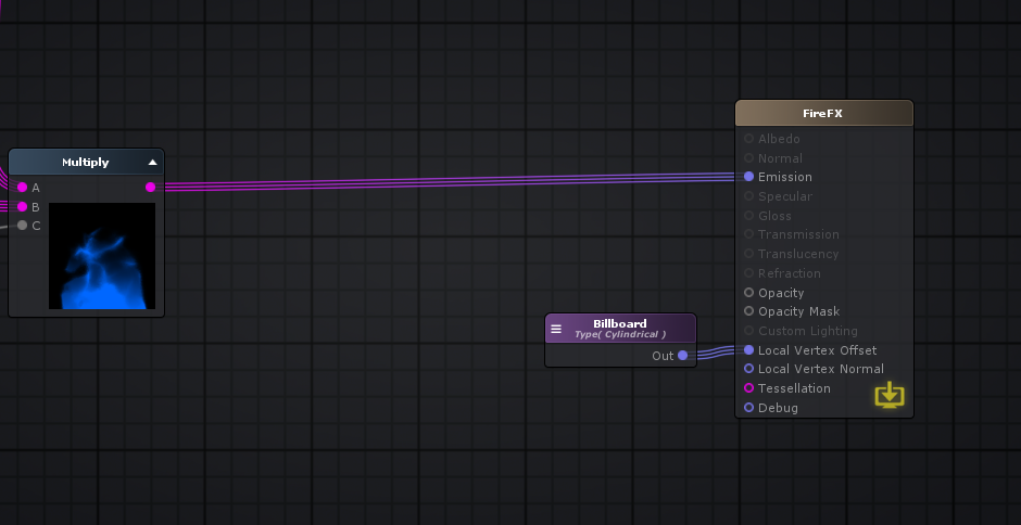
everything to the left is entirely for the visuals
(this is amplify)
Not sure if shadergraph has a billboard node
you can do operations on the node
Do you have to create the billboard logic in shadergraph or is there a node for it like in amplify?
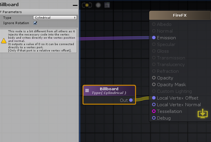
https://wiki.amplify.pt/index.php?title=Unity_Products:Amplify_Shader_Editor/Billboard
Billboards can be set through its Type either as Cylindrical where only the object X and Z axis are aligned with the camera ( useful when rendering trees ) or as Spherical where all axis are aligned.
Also, through the Ignore Rotation parameter an object's initial rotation can be either completely ignored and overridden, or it can be used as a delta rotation over the billboard final calculations.
Mhm I've checked this documentation already
The rotation has to be cylindrical
Whether ignore rotation is on or off, it will still cause the issue
Based on this node being unique I'm not sure if you can split it
Would breaking it into xyz components work or nah?
I was also possibly thinking that if I could just recreate the billboarding logic on my own, and then working off of that, that would work
i could even make a custom node
Yeah that was my thought - since what is controlling the vertex offset is a vector 3 - XYZ coordinate
it will work, amplify is not like shader graph it doesn't need a split node to get the child of a node
In Shadergraph I would do Split -> Combine output vector 3
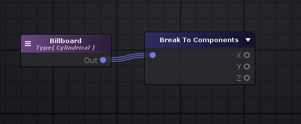
I can break into XYZ
but im not sure if this will work
unless im using the wrong node
did you mean like this?
worth trying
no bueno
figures
Well the entirety of the billboard logic is based on the camera's inputs
so me changing the output of the billboard node probably wont work right?
I need to actually change how the billboard is reading in the camera inputs
to ignore its Z
can you override all of this in the camera
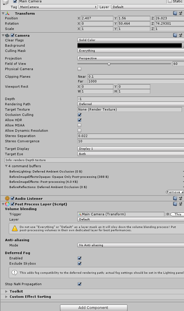
wait hold on
I have a plane with a shader that is billboarded to always face the camera, and it works just fine
Can you freeze the z rotation of the plane in the inspector?
I mean you could add a rotation constraint component
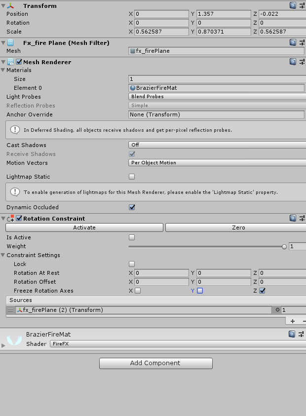
it constrains the child's rotation to that of it's parents
I doubt any changes on the cpu side will help, since the shader is modifying the vertices on the gpu
You likely need to look into handling the billboard yourself, I guess the built-in amplify node expects the camera not to roll?
This rotation constaint is more during runtime when you might have physics moving the object
It must expect the camera to not roll
but that seems odd
Camera roll in games is extremely common
especially in VR
I think I mentioned this earlier
any game that billboards grass or vegetation will have this EXACT issue
so im confused as to why this doesnt seem like a more common problem
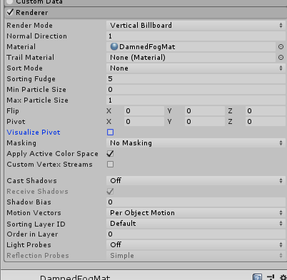
the funny thing is that this issue can be solved in a particle system
there's an "Allow Roll" option in the render settings
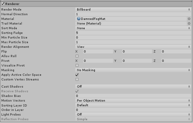
right in the middle under Flip
when you used break to component node you have set the billboard to a vector3 and you set z = 0 but you didn't plug it in so it will take the default value from the rotation i assume that is what happening
it should take 0
I already tested that too
if I put in 1 instead, it will just move the plane back
but the issue still persists
what if you made a subgraph for the billboard node - set that subgraph's output as a vector 3, then split and combine
?
not sure
did you see this stipulation listed on the documentation?
NOTE: Billboard node should only be connected to vertex ports.
by subgraph do you mean my own graph for billboarding?
Yes its connected to the vertex port
I think it's actually very similar to shadergraph
I'm pretty sure they are using the node correctly, I'm guessing it just doesn't have proper support for camera rolling. It does seem odd, but must be an Amplify thing. I can't find much resources on it.
I can't either
Yeah I'm struggling to find much either
and I'm not sure why
it seems like something people would run into really quickly when doing anything VR related
You could perhaps look into billboarding with a C# script (transform.LookAt kinda thing), instead of shader related
wouldnt that be a lot more performance taxing?
Or try and handle the billboarding yourself. I've used this in shadergraph, but I don't think it will be much help for Amplify :
I'd prefer to do it in a shader ideally
Those nodes all exist in Amplify
they are just called different things
I'm guessing you've already come across the suggestions in this forum thread:
https://forum.unity.com/threads/camera-facing-billboards-for-vr.453807/

Unity Forum
Camera facing particle billboards for VR. Has anyone managed to stop the rotation of them when rotating heads.
See here:...
Yep
I'm using 2015 VS community edition and it's ass, doesn't load
so i need to get 2019 tonight
quick question, will 2019 vs community edition work with unity ver. 2018.4.20f1?
It's the version required to be used for VRChat
Should mention, the billboard thing I posted above would go into the Vertex Position input on the master node in shader graph. But looking at Amplify, I think "Local Vertex Offset" is, well an offset, so I assume will be added to the original vertex position. I guess you might need to subtract the vertex position to account for that?
So I think what I will do is recreate the billboard effect in Amplify as a series of nodes, but I am going to take a break for now
I may be back later if I run into a wall again
do you mind if I @ you then?
Don't know if I'll be much help with Amplify, but sure. Might also be offline, it's getting late here
So all that matters is the logic
you can usually perfect translate shadergraph to amplify
Is there any way to create height based fog on a lit graph? Can't think of a way not to have the faked fog be affected by lighting. I'm thinking of going the unlit way and implementing the light/shadows before the fog.
Hi guys! I was wondering if there was a way to fade in and out objects in URP? I looked online and it seems like people recommend changing the MeshRenderer's alpha value, but it seems like there is no color property in URP's MeshRenderer. I'd appreciate any help.
Okay so, using
obj.GetComponent<MeshRenderer>().material.GetColor("_BaseColor").a
andobj.GetComponent<MeshRenderer>().material.SetColor("_BaseColor", fadeColor)
seems to let me change the base color of my objects, but I had a question. First of all, does this change the material property for every object using this material? And also, I'm using an outline shader, and this transparency thing only works on objects set to "transparent" instead of opaque. When an object is set to transparent, it seems to show all the outlines that are normally hidden behind it. How do i go about fixing this?
Hi, does somebody know how I apply CullOff on HDRP Shaders?
Properties
{
_MainTex ("Base (RGB)", 2D) = "white" {}
_Color ("_Color", Color) = (1,1,1,1)
_Distortion ("Distortion", Range(0,1)) = 0
_Alpha ("Alpha", Range (0,1)) = 1.0
_Speed ("Speed", Range (0,1)) = 1.0
...
For Shader properties:
Is there a type for "Float2" or do I have to have two separate properties for this (for X and Y coordinates)
nvm found a good cheatsheet https://gist.github.com/Split82/d1651403ffb05e912d9c3786f11d6a44

Gist
Unity Shaders Cheat Sheet. GitHub Gist: instantly share code, notes, and snippets.
shader code is so fascinating, once you get something to work, it feels lovely
I'm still a noob to shaders, but writing shaders is so beautiful
        void surf (Input IN, inout SurfaceOutputStandard o)
        {
            // Albedo comes from a texture tinted by color
            fixed4 c = tex2D (_MainTex, IN.uv_MainTex) * _Color;
            float3 localPos = mul(unity_WorldToObject, IN.worldPos);
            o.Albedo = sin(localPos.x*8);
            // Metallic and smoothness come from slider variables
            o.Metallic = _Metallic;
            o.Smoothness = _Glossiness;
            o.Alpha = c.a;
        }
I can't figure out why float3 localPos = mul(unity_WorldToObject, IN.worldPos); won't give me the local position. The material on these two cubes using this shader should show the same black/white pattern if it was using local space, but instead it changes with the cube position, as if I was using world space.
multiplying by a constant matrix seems to work. Is unity_WorldToObject not filled in or something?
I read that unity_WorldToObject doesn't work with dynamic batching, but I disabled that and it still doesn't work
finally got it to work with a vert section
Is it possible to do Custom ShaderGraph material property overrides
[MaterialProperty("_Color", MaterialPropertyFormat.Float4)]
public struct MyOwnColor : IComponentData
{
    public float4 Value;
}
(found here: https://docs.unity3d.com/Packages/com.unity.rendering.hybrid@0.8/manual/index.html#built-in-material-property-overrides-v2-only) in a custom shader?
Can somebody tell me if I got this right?
In clip space the far plane is at z = -1 and the near plane is at z = 1
@tall rampart Did you see this too?
https://docs.unity3d.com/Packages/com.unity.rendering.hybrid@0.8/manual/material_overrides.html
@fair sleet Depends (groan) on OpenGL vs DirectX. IDK about Vulkan.
https://answers.unity.com/questions/1443941/shaders-what-is-clip-space.html
Unity is the ultimate game development platform. Use Unity to build high-quality 3D and 2D games, deploy them across mobile, desktop, VR/AR, consoles or the Web, and connect with loyal and enthusiastic players and customers.
Let me get this straight
in OpenGL the z coordinate of the clip space is from 0(near plane) to 1(far plane)
in DirectX the z coordinate of the clip space is from -1(near plane) to 1(far plane)
This applies in the fragment shader, correct?
If you sample the depth texture and make it linear with Linear01Depth() it should always be from 0 to 1, right?
as I understand it using the linear01depth macro should give you that, while lineareyedepth is in "world space"
hello i m looking to do particle system with compute shader do you have any exemple to give?
Is there a minimal template for a vertex/fragment shader in URP?
@supple kiln If you're doing it "for fun" and want to do it yourself, you "roll your own" however you want to do it. Any of the compute shader examples will get you started processing a buffer of some sort, then look up some form of procedural generation or billboarding to draw the particles at various locations. You'll want shader experience.
Or "for real" just use VFX Graph, that's what it's for. 2-cents.
@teal breach Maybe try going after URP source and just look at the unlit shader. It's on github, google is your friend.
thanks CarpeFun
@teal breach I've got this, quite minimal I think. https://pastebin.com/E3tmPZis
Doesn't have shadowcaster or depthonly passes though. So won't support casting shadows or depth prepass (in order to appear in depth texture)
still useful - I haven't written a shader for a few weeks and it's the macros/features I forget!
pragmas, etc
That's why I prefer working with shadergraph 😄
Sometimes gotta use code though, if you want stencils, geometry shaders etc.
How can I convert a position in clip space back to world space in a fragment shader?
If I multiple the position with this matrix will I get the correct result?
Matrix4x4.Inverse(Camera.current.projectionMatrix)
Why not just pass the world space position through to the fragment?
I can't.
This is a shader made with your Blit render feature.
I'm getting the position using the depth texture. I'm relatively certain this part works but I don't get the correct result so maybe I am multiplying by the wrong matrix?
I usually use the following in shadergraph for reconstruct depth pos in blit. I assume this would work if converted to code too.
Using unity_CameraInvProjection and the _InverseView matrix property sent in via my Blit Render Feature (if the checkbox is ticked)
Is this a correct way to calculate the position? This runs in a frag shader
// screen color
float3 color = tex2D(_MainTex, i.uv);

//get linear depth
float linearDepth = Linear01Depth(tex2D(_CameraDepthTexture, i.uv));
if (linearDepth == 1)return color;

//calculate pos in clip space
float3 pos = i.vertex;
pos.z = (linearDepth)*2-1; // -1 is near plane, 1 is far plane for directx

//convert clip space to world space
pos = mul(_InverseView, pos);
No idea really. Converting from clip space to world would likely include an inverse projection matrix as well as the inverse view though.
Like, Inverse Projection * Clip = View, Inverse View * View = World. Unless I'm mistaken.
That's basically what I'm doing in mine. The first part is the converting to view, which could likely be moved to the vertex shader to be more efficient, but can't do that in shadergraph. Then the second part is setting depth in view space (so it doesn't need to mess around with the clip space z differences I think?)
right,
how to I get this inverse projection matrix?
I think just unity_CameraInvProjection. Seems to be a built-in thing. Might be somewhere in the URP library
I added pos = mul(unity_CameraInvProjection, pos); but it didn't work
Might need to be a float4, with w=1. Idk. That's what I'm doing in my setup.
Might be able to look at https://github.com/keijiro/DepthInverseProjection/blob/master/Assets/InverseProjection/Resources/InverseProjection.shader
I think that's what I based it off originally, though had some edits because of shadergraph specific stuff, and used eye depth instead of linear01
It didn't do anything, I think it assumes w=1 for float3
Hey there! Is somebody familiar with Blender to Unity textures?
Because I just baked a texture in blender, and it works just fine there, but in unity its messed up.
@regal stag #archived-shaders message
I’ve only just realized that what he is doing via script is flipping the normal of the clipping plane only where the two objects intersect. 
How could I set it up so the clipping object would display a different material depending on what object it was intersecting?
I saw you mention the render objects feature with an override material or just having multiple materials on the mesh renderer - but which mesh renderer? The clipping object right? Not the object being clipped?
Would I need to UV map for multiple textures/materials based on the object being intersected/clipped somehow?
Thanks for all your help on this. It’s been surprisingly more complex than I thought and very interesting.
@true steppe what do you mean? Do you have some screenshots of it?
@solar sinew Not too sure what you mean by "clipping object". If you mean the object with this CrossSectionPlane script then no. I think that's likely just an empty gameobject with the transform to show where the clip will take place and send the position + forward vector into the shader. It could have a visible plane mesh, but that isn't important, just for visualisation purposes afaik.
In the tutorial example you linked, they have a heart and a hologram version. I think they have it set up as two gameobjects, but since they are the same transform and mesh, it could just be two materials on the same MeshRenderer.
Ah okay - one thing I was wondering is what I would need to change in the graph/script to use a sphere rather than a plane. Should I use a vector4 to control the sphere’s radius as well? Or because I would be modifying position transform the property should stay a vector3?
For clipping based on a sphere you'd need a vector4 yeah, xyz being the position and w being radius. I guess you could also use a vector3 and vector1, but it makes sense to pack them together in the same property. Can always split it in the graph later.
After I achieve the cross-section visual effect I’m going to integrate this shader with my camera system; setting the sphere’s position based on a raycast from the camera. In that case should the raycast from the camera be a vector4?
When setting it in C# you do something like material.SetVector("_Sphere", new Vector4(raycastPos.x, raycastPos.y, raycastPos.z, radius));
You wouldn't need a normal for the sphere
The normal is needed for the plane since in order to define a plane it needs a point and normal to determine it's direction. A sphere just needs the point and radius.
Unless you want to also be able to say, clip inside sphere vs clip outside sphere, that could be an additional vector1 to send in.
In terms of getting a sphere to clip in the shader, you'd use a Distance node with this sphere xyz, and world space Position. Then Step with the radius. That could be used as the alpha input with a alpha clip threshold of 0.5.
I want to be able to clip inside the sphere - and make the object being cut appear to have thickness rather than just a hollow object. (I don’t know why I initially said hole in the mesh)
I was asking about whether I needed a sphere normal because I would want to flip the parts of the sphere (display the backface) intersecting my wall object to make it appear to the player that they are viewing the wall’s interior
Right, you want an actual surface where the intersection takes place. That's a much more complicated effect.
For the plane it's fairly common to have back faces enabled on the mesh so that when the plane clips it, it makes those backfaces visible. They won't be lit correctly since the normals of those faces won't point in the right direction. I guess you could set the normal of the back faces to the _PlaneNormal sent in though.
For a sphere, I'd need to test it. I'm a bit unsure how you'd calculate it off the top of my head
Yeah I’ve been trying to figure it out - most tutorials examples use a plane. I have seen examples where they’ve used a cube (three intersecting faces) but a sphere is more complicated
Also, for texturing the plane one - Remy has done a graph that does that, I think using a matrix sent in. #archived-shaders message
Ooo
Hm or maybe it wasn't a matrix looking at the script. Maybe the matrix was constructed in the graph? I seem to remember a matrix being involved when I looked at it, but I might be misremembering.
Also, this intersection-sphere thing reminds me of an example stencil effect at the very bottom of : https://docs.unity3d.com/Manual/SL-Stencil.html
Might be easier to do it with stencils rather than culling (don't have to mess around with faking surfaces (including normals/uvs) with back face geometry, as there's a real sphere being drawn, just stencilled out a bit)
My initial approach used stencils. The method I was using had two render objects features - one for a mask layer, and another for a see-through layer.
One concern I had is that because my player can pivot the camera around the house (think animal crossing house camera behavior), I would need to be changing what layer the closest walls were on whenever the player rotates the camera. Otherwise the sphere just acts as a mask for the closest wall and the furthest wall
Oh right, the stencil approach might not work for that use case. It's kind of a fake effect as the scene is rendered completely normally, just overlaying part of the sphere cut out where it would intersect. It wouldn't actually remove the geometry allowing you to see through the walls. :\
Personally I think the culling approach is fine with a flat colour, but I guess it depends on the art style too
We have a more toon-look so I was imagining the interior of the walls either being a flat color or very simple texture
Here’s a test scene following this simple stencil tutorial. The character is representative of art style rather than these walls
https://theslidefactory.com/see-through-objects-with-stencil-buffers-using-unity-urp/
Yeah I’m thinking using the sphere as a culling object is the way to go. Going to work on this sphere math now
Just ask the question and if someone has any idea and has the time to answer, they will
I'm sure you've done this before
so i have a shader for the particles mats, so i have a mat with the shader then i give it a texture and then i give the mat to particle and the particles become invisible
What shader is it?
its a unlit shader graph
how to make mobile friendly refraction? I'm still kinda new to shader programming
and shader graphs seem like something that's performance heavy
mentall NVm i fixed it
@compact pine The only way to do a mobile friendly refraction is if the thing being refracted is pre-baked
Like a baked reflection probe
if I understand correctly I need to know the exact texture for that?
Know the exact texture? I don't follow
ok sorry. so my game generates its map
can I still use this?
I guess I don't really understand what baking means here
I mean what you're refracting isn't what's actually behind the thing
Because the thing that makes refraction costly is getting that texture of what's behind an object
Especially on mobile
What do you want this refraction for?
making an ice map
And it's just a visual effect. Can probably do it without refraction.
so like it needs to refract obstacles
Sounds like there's no way to bake it
An example of something you could bake is if it's a static scene with one window in a static place. Nothing is going to change behind that window, so you might as well make it a pre-made texture rather than dynamically fetching it every frame
But since your map sounds like it's procedurally generated, that's not an option
well thanks anyways. can try to fake it with textures I guess
Is it possible to make a transparent lit urp shader throw a shadow?
for some reason, blit refuses to show up as a render feature all of a sudden
it was working fine earlier today
upon opening my project, i recieve this error in my renderfeature asset, and i notice that none of the custom render features show up
oh, it seems like it broke because i had script errors on an unrelated script, weird
Hi, I know there was a way to get copies of unity built-in shaders in your project, but don't remember how this worked.
I have never touched actual shader code before, so i have no idea why this error is occuring
I miss the shader graph
I thought i had declared it
where was it declared?
but it doesnt look like its a known part of the shader itself
what?
i might be wrong, as im pretty new to shader stuff tbh-
Well you see i have pretty much no idea as i would just use shader graph
but being i have to use unity 2017.x
that doesnt exist
https://docs.unity3d.com/2019.3/Documentation/Manual/SL-UnityShaderVariables.html so it seems like its not in the list of variables
I figured it out...turns out you have to also put it here;
and look at that, here i was thinking that making proceedrual terrain in unity 2017.x would be a nightmare...
I was only half right!
whaa- thats so confusing
Basically it's just plopped into the middle of a terrain object as i am too lazy to make it so that the character spawns on top of it, so they clip
maybe use raycasts to check where the player could spawn without clipping?
No i know how, it's just currently i have done a ton and that is something for another day
ah
Hi folks, i can render the opaque texture and the depth texture to 2 planes as u can see.
what next is i want to exclude the 2 plane from those textures, so in the 2 planes only the scene ground plane and the cat girl is visible. Is there a way to achieve this ?
render the planes as transparent and zwrite off would be the simplest way
@paper anchor I had the same issue and couldn't solve it. Switched to blitting to the texture array instead.
@low lichen I'm sorry but I am not sure how I could exchange my system with a blit... because I need the compute shader to have access to the whole array of RenderTextures at runtime, since each thread independently picks one of the slices to draw on based on other input info... maybe you mean blitting to a Texture2DArray? Would that work on Android? But if I have like 20+ rendertexture slices in the rendertexture array then I expect the overhead to be massive since I do this each frame...
Any tips to make an outer glow shader without Shader Graph without bloom? I want to use ".shader" coding. One way I thought of is just doing Gaussian blur, but there might be a better way.
@paper anchor You mind if I ask what you need 20+ slices for?
If you have the distance function for the shape you want to add a glow to, you can just resize that slightly, make the edges a bit soft & add color to it
I'm trying to use a depth mask in URP, but instead of seeing the background on the GO with the mask I get gray. Do you have any idea what that is?
Is it possible to make a transparent lit urp shader cast a shadow?
@shrewd mist yes it is possible but it won't be an lit shader any more since the lit and Unlit are the ones you should use if you want to make the performance shader fro mobile
so you cant do a lit shader?
i had an unlit shader for a while and pushed it to its limit but then i realized lit is 10x easier
I was just asking whether it's possible to make the standard urp lit shader cast a shadow
But if that is not possible, is it possible to write your own shader for urp that does that?
oh
With the surface type transparent
ohh
@shrewd mist in shader graph i have no idea how to turn the lit master node to cast shadows.
but for the shader code you need to calculate it and add the cast shadow attribute in the shader pass
Alright, looks like I have to get into shader programming then x)
I thought I can maybe avoid it since it's kind of a big topic
you can just use the PBR master node since you are looking for shadows
Hey, does anyone remember, where you can find Unitys built-in shader scripts? like "Mobile/Bumped Diffuse" or just "Standard" - so can do a copy of the .shader file and put it in my project?

GitHub
Unity Built in Shaders. Contribute to TwoTailsGames/Unity-Built-in-Shaders development by creating an account on GitHub.
GUYS anyone else noticed that we cant change the colors in shader graphs in latest LTS version 2019.4.13
we cant change the color in properties or the albedo or emmison or basically anything that requicres the color pocker box in shader graphs
Pls tell me how to fix this if i am wrong
@low lichen @fast skiff https://unity3d.com/get-unity/download/archive click on the "Downloads (Win)" or "Downloads (Mac)", you'll find built-in shaders for every single Unity release here (except for alphas and betas which has similar link on the specific alpha/beta download page)
no need to go for unofficial 3rd party repos for this
@fervent tinsel thank you, but wasn't there a folder (that came with unity) where i can get shader duplicates from?
or did that change after Unity 2017?
@fast skiff I've never heard of such thing, afaik it's always been like this with Unity
you refer to the decompiled c# code repo now?
if so, that's a totally different
Is there a way for me to edit the material in Photoshop? It is a Microsoft Acces file
When I press ''Show in explorer'' it shows this
It's a file from the Assets store
It's not a Microsoft access file, it's just they probably use the .mat file extension for something too and it's assuming that's what it should be opened with. In this case unity's material files can be opened with a text editor - but since you are referring to Photoshop you probably want to open the textures (probably .pngs or something), not the material file.
@fervent tinsel can't remember exactly. i created a shader for seasonal textures with Unity 2017 and got copies of different regular shaders to "upgrade" them to be seasonal too.
like "Mobile/Bumped Diffuse", etc. made a "Seasonal/Mobile Bumped Diffuse" from the copy.
AFAIR they where stored in some library folders of unity and someone back then told me where to find and how to get the copy in my project for modification.
But I can't remember how it worked exaclty. Maybe it really was downloads? have to check your link @fervent tinsel
@regal stag Thanks very much, I was looking for the textures indeed haha. Stupid of me
point is: just need a triplanar shader with normal map support. I have a regular one (only diffuse), so i need to look up how the "Standard" or any other of the regular shaders is scripted correctly, then I can add the normal maps myself to the .shader script.
Don't need HDRP/URP yet, working on the basic code. So no ShaderGraph, just want that script updated by myself, as I can't calculate correct UV-values for procedural meshes.
Alright, looks like I have to get into shader programming then x)
@shrewd mist
Shadows on transparent objects have been a problem in all pipelines, but with URP it's "new" and not well documented yet. For your web searches, what you're looking for is a "ShadowCaster" pass. What it does is render the object again, with a simple depth shader, using the light source as the camera position, into a shadow map. But transparent pixels are hard to handle, as you say, you'll have to customize the pass. And you're not going to get "greyscale" shadows. What you end up with is just the object depth value from the light's perspective, not any intensity of light. Google is your friend.
Thanks CarpeFunSoftware!
I'll try my best, this seems to be a hard one
So, when I want to create a regular shader graph I use "Create > Shader > PBR Graph", right?
If you want PBR lighting, yep. :)
You can then "view source" and go from there, edit it if you want.
I will try to recreate the regular lit shader and then add what you mentioned
I think the PBR graph will automatically have shadows with transparent surface too, so just need to replicate the textures and stuff
@regal stag That would be great!
SG is a code generator. So you can see what it outputs.
Yeah, like Cyan said, it will already have a pass that you "just" need to customize
@meager pelican Where's the "view source" you were talking about?
I completed my regular transparent lit shader, but where is an option to see the code?
@shrewd mist right click on the master node in SG and click on generate code
Ah great, that works!
And now I just edit that?
Ah no, I probably have to save it to somewhere
Anyone know if theres a particular channel I should be outputting specifically for coat masks?
Weird, I just noticed that that my shader graph shader doesn't even cast a shadow when it's opaque
Hey people i am in a huge pickle i want to make a terrain mesh blend shader but for the love of me no one made any online on hdrp or urp on shader graph does anyone of you have ANY pointers on this?
Okay, great thanks to @hearty stump , @meager pelican and @regal stag , even though in the end I solved my problem in a different way entirely :D
Question: Anyone here, knows a Unity "Default" Shader, with all possibilitys ( indeed: important are: Smoothness, Second Albedo + Second Normal Map )
What can fade 2 textures ?
( Height, Occulusion and other are not important, but second albedo / most important: 2 Albedo Textures, and 2x Second Normal Map ).
@river jasper The unity default shader does what you're asking for ... Or is it for URP maybe ?
no, i need to change 2 textures in Runtime.
now: i got Shaders for changing Albedo 1 to Albedo 2.
Also i got a Shader, can change from Albedo 1, to Albedo 2, or 1 to 3 and so one.
but following Problems:
-
- none of this shaders, have a smoothness,
-
- none of this Shaders, have a second Albedo or a Normal Map option.
They change the Texture in Runtime - okay. But the 2th Normal Map, cant be addet.
Also there is no Option, to add a first Normal Map.
i hope you understand, me is german is a little hard sometimes to explain such things in english 🙂
Is it for doing a "smooth" change ? or a pure texture swap ?
yeah.
smooth, in runtime.
if i just want to change the Texture in 1 hit, i can change the material, this is no problem.
so for example: if i want to change the "Material" - no problem.
if i want to change the Texture of the Material - no problem.
but this all is a "Switch" / "Swap".
i need this smooth, with 2 overlapping textures 🙂
By smooth I meant "the base texture should gradually change to the 2nd texture in a certain amount of time" VS "the base texture changes to the 2nd texture in one frame"
yes, take a moment, i write you a PN 🙂
No PM please if this can be answered here
fun in shader graph, I've got a shader setup which was using camera depth (for a water shader). Got some nice displacement going, normals etc. all setup, using camera depth to reduce displacement near to shoreline.
That all works, but then I decided to swap to a baked depth texture due to obvious limitations / quirks of cam depth.
It works up to a point, I can either do vertex displacement or the surface color. BUT not both together, which I'm assuming is because I'm sampling the texture in both fragments but I'm making sure the sampling is separate (or appears so in the graph). Which worked when i was using _CameraDepthTexture but not now I'm using my own.
Is this a bug or am I perhaps overlooking something?
You can't "bake" a cameraDepthTexture if the camera moves. It's relative to the camera pos. But you can compute depth based on camera pos and world-pos distance. Or I'm not following.
hard to explain... the depth aspect works fine, I've just swapped from using the _CameraDepthTexture to a static baked depth texture. Which I have setup, gets world position etc all aligned.
Problem is I can either use it in vertex displacement OR when I'm adjusting colors... not both as I could when using _CameraDepthTexture
If that makes it any clearer
So depth is Y depth from water? Or you want to know how to calc that?
There's the water-depth, and then there's the "camera scene depth regardless of water".
And figuring out what your "camera view ray" is going through is a bit tricky.
In the former, you know the pixel world-space pos and you know the "bed" worldspace depth from the plane, so you can add/subtract that all up to get the Y depth.
But your view ray is going through a stuff at an angle.
😉
no everything "works" just not together, I will do a simplified shader which will hopefully explain the problem or it will work and I'm barking up wrong tree 😄
@river jasper did something like this for seasonal textures in unity 2017 - maybe it still works? but not sure, if they had normal maps
Short:
VERY THANK YOU TO REMY HELPS ME OUT
Thank you, this is one of the Reasons, i love unity so much. Most of us, stand together!
@river jasper sorry it is only for Diffuse channel.
If you know how to get copies of the included unity shaders, you could maybe modify it, so it can blend with normal textures too
@river jasper Do you want that shaders?
ok, fine 👌
@fervent tinsel You where right! it was always needed to download them. Thank you!
hello aynone here?
can someone help me, i cant really explain my problem btu i can show you
please tag me
In URP 10 I get an issue with "#if SHADERGRAPH_PREVIEW", the error I get is: "invalid conditional expression" anybody know how to fix this?
Is it any different if you use #ifdef instead of #if?
Can you add emission to vertex/fragment shaders? Or only surface shaders?
I thought I answered this question for myself a while ago but the more and more tutorials and write ups I look at the more confused I am.
Is a sphere's normal vector a vector 3 or a vector 4?


a normal is a line that is perpendicular to a surface
a sphere as infinite hypothetical normals
that said, normals are negerally v3's
Need some help with a vertex fragment shader
@karmic delta Emission is just a color that you add at the end after you've calculated your lit Albedo color
half4 finalColor = half4(litDiffuse.rgb + emission, alpha);
@honest bison Ask away
I've got a bunch of lighting and reflection to bring together and I am not sure how to do it.
I have diffuse light, specular reflection, fresnel in the vertex program, which I am sending to the fragment. In the fragment I am sampling albedo and metallic/roughness. the roughness is being used in a texCUBElod. I know about all these things, but just not how to bring them together in a meaningful way.
I am trying to make a cheap PBR type material.
Doing most of the calculation in the vertex program.
No normals.
Specular highlights and fresnel are similar to emission, just added to the diffuse light at the end
Single light.
I have added them all together - but then when I add with the albedo its too bright.
Which part is making it too bright? The fresnel?
Alright who here has a big brain and could help me out 😛
I've run into a sort of math issue
@honest bison That's just the diffuse light or also the specular and fresnel?
I need to convert a directional vector into a euler angle
@grand jolt In a shader?
Mhm
What do you need euler angles for in a shader?
I'm currently in Amplify
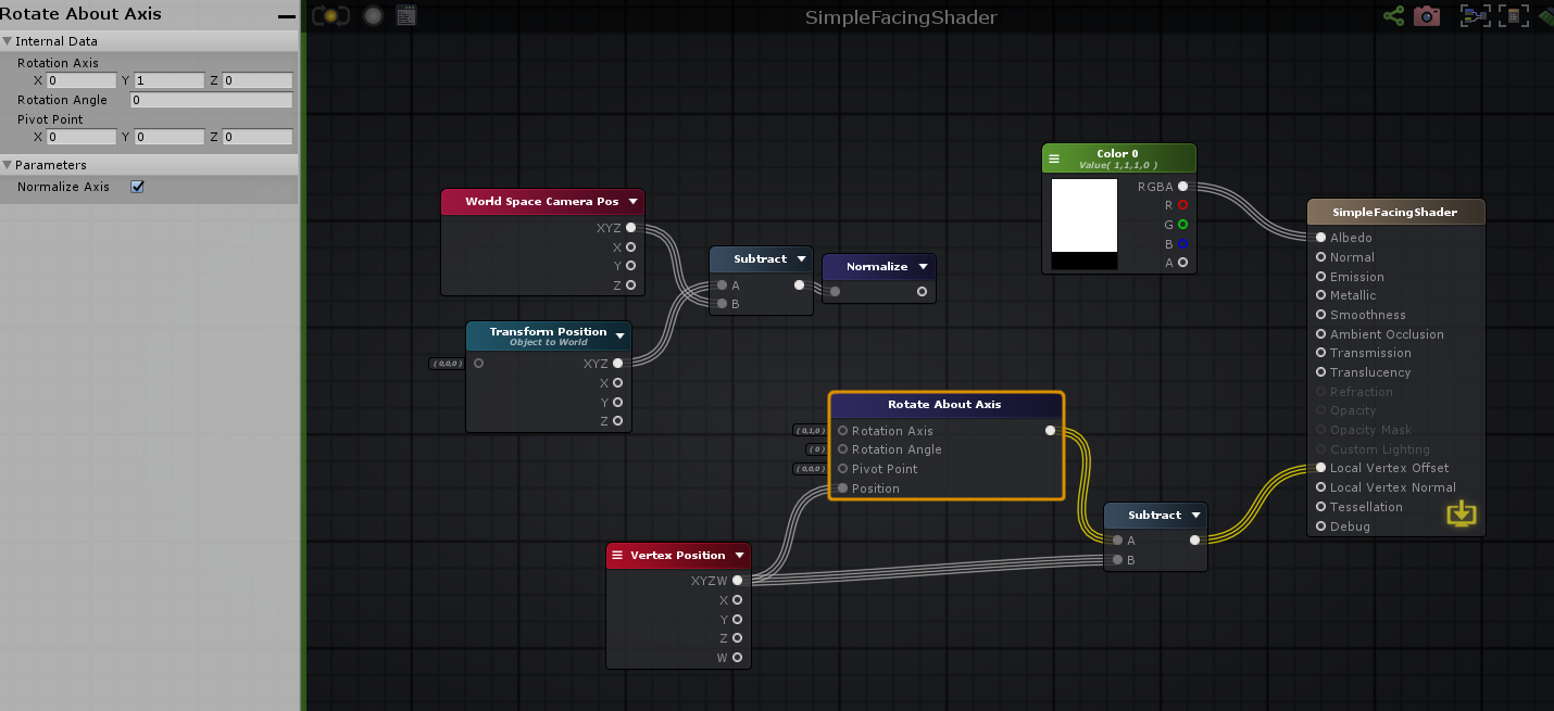
I am making a shader that makes a mesh always face the camera's position
and no I don't mean billboarding
That is the lambert, phong, and fresnel
it's essentially a LookAt but in the shader
But this could also theoretically look at a player or another object's position if I wanted to
but that isn't the goal
So far I've created a directional vector by taking the world space camera pos subtracted from the object's world space pos and normalized it
I have a rotate about axis node that takes in a rotation axis (currently 0, 1, 0) an angle, a pivot, and vert positions
Using Euler angles in a shader makes little sense to me. It's just a human friendly format for rotation, while Quaternions is what Unity actually uses internally
Sorry maybe I am messing up my terminology
Just for clarification
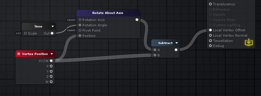
if I plugged in a time node into the rotation
it would look like this
(i put the shader on a simple cube)
Anyways
Do you just want to rotate it on that axis?
yep
Not all axis?
Then you just need to calculate the angle needed to get the right rotation
so basically i just need the angle to be that which always matches towards the camera
yep
that's the part im stuck on
And this is basically in 2D because it's only on that one axis, so you should be able to use Atan2 to calculate the angle
Im pretty sure this is important
but the input for rotation angle on that node doesnt seem to be between 0 and 360
It's probably in radians
maybe
Which Atan2 returns
im about to test
yea it has to be
because 6.28319 seems to be a full 360
so how do I use atan2 to get the angle i want?
There's an example here
https://docs.unity3d.com/ScriptReference/Mathf.Atan2.html
Don't need the * Mathf.Rad2Deg, though
oh yeah im on the amplify wiki as well
i see it
I'm just not understanding how to actually calculate the angle, whether its degrees or radians
all I have is a directional vector based on the camera and object's world pos
In this case, you would probably give it the X and Z of the direction
of that vector?
Fuck me, you're right
I don't care about the shading because it's going on unlit shaders
What are the chances you've ever played VRchat or worked with VR in Unity?
I don't know if you care, but I can tell you why I am doing this
100%
VRchat?
I've played it and messed with the SDK
if you've ever played in VR, you might have noticed how bad particles and billboarding is
it just fucks up wildly
and I've been asking around a bunch of discords trying to find a solution and no one knows
in VRC if you rotation your head left and right, billboarded sprites will just wobble left and right as well
which makes no sense
and its even worse if you tilt your head
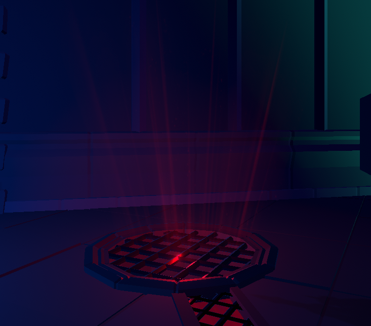
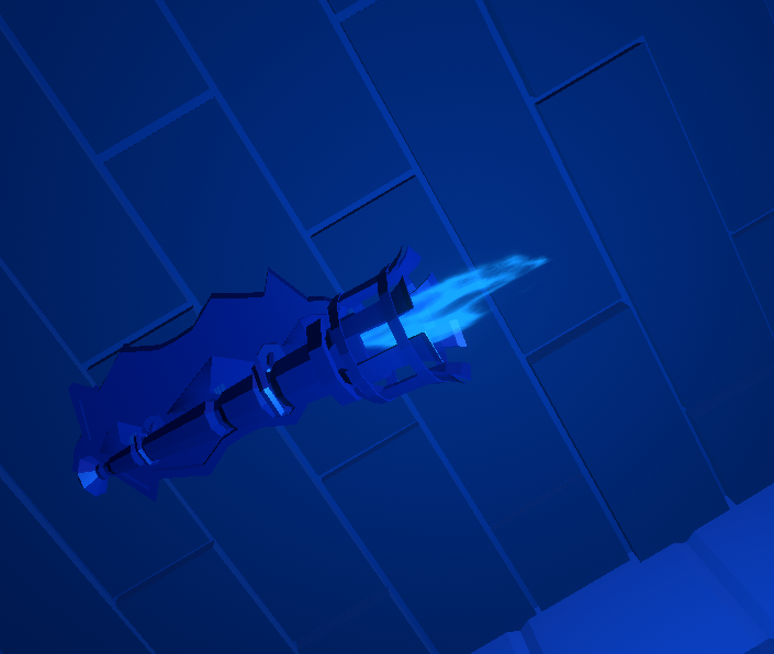
Like here's a light shaft that's billboarded right?
If you tilt your head in game

it squishes
Makes sense now why you want to do this in a shader rather than in script, since you can't use scripts
👍
exactly
Anyways
I was showering and I was just thinking
why not, instead of having the quads face the cameras view
just have the quads face towards the cameras position
I went to a bunch of worlds as well just to make sure I wasnt the only one with this issue
alot of big worlds also have this exact problem
and I think this will fix it
This new shader isnt affected by camera roll, or the angle you face your camera at all
it just looks at the camera's position
Particles have a billboard facing mode that does the same thing
Really?
Not sure if it also ignores camera tilt
In the Renderer part of the particle system
not seeing it
I might be blind
oh
i see it
you have to be specifically in billboard
https://docs.unity3d.com/ScriptReference/ParticleSystemRenderer-alignment.html
Particles can face the Camera in two ways:
- Aligned to the Camera plane, so that all particles are aligned with the same facing direction.
- Aligned individually to face the eye position, which can be more convincing for particles that approach the Camera in close proximity or for VR environments.
you've been extremely useful
Now I have to test it in desktop, and then in vr
to see if it truly works
Hi! I'm new on Shader Graph, and I already have an issue. I can't edit the color of a Color Node. When I click on the black area, nothing happens, the color window does'nt open..
Any idea of what happening, and how solve it ?
Thanks
Hello,
I want to do a unity particle system with computer shader.
When i click with my mouse on the scene i do particle.
At this time when i click on the scene nothing happen and my mouse position is always 0,0.
Here is my code : https://hatebin.com/jgkwwgrqqq
Description of what i want :
-
Get the position of the mouse in the OnGUI () function, use the Camera.ScreenToWorldPoint () function to convert the screen coordinates of the mouse into world coordinates.
-
In a Compute Shader, animate the particles using the pseudo-random number generation formulas described here http://www.reedbeta.com/blog/quick-and-easy-gpurandom-numbers-in-d3d11 /, generate a random position (3 float-s) for the particles.
-
Optionally apply physical parameters (gravity, etc.) passed via a Constant Buffer.
-
In the OnRender () function use the DrawProcedural () function to draw the particles as points.
-
In the Vertex Shader, we must then index our StructuredBuffer of articules using a parameter of the main function with the semantic “SV_InstanceID”.
-
Rather than displaying a single point, we add a Geometry Shader to generate a square of the size specified via the Constant Buffer.
-
Use the “life” of the particles as a transparency factor. Use additive blending - Blend one, oneMinusSrcAlpha.
For the rendering to be correct, we will pre-multiply the RGB components by the Alpha in order to make the composition of the colors independent (no need to sort the particles).
What's the question here ?
At this time when i click on the scene nothing happen and my mouse position is always 0,0.
Vector2 mousePos = new Vector2();
Debug.Log(mousePos);
This will likely always log 0,0
Mouse position for event is only valid if Used in EventType.MouseMove and EventType.MouseDrag events.
RTFM
i put the log at the wrong line
but my main issue was when i click none particle spawning.
I think we should move this discussion to an other thread, as it's not purely shader related, maybe #archived-code-general ?
Anybody know what's causing the above error? ^
I've had nothing but trouble since upgrading to Unity 2020. VS keeps un-attaching, keeps saying files are missing, etc. The main thing is that I can't use a bunch of nodes in ShaderGraph any more. Anyone get any idea what might be producing this error? Can't find anything helpful anywhere on Google
I've never seen this before.
Aside from upgrading the editor version, did you check that the packages version are also upgraded and updated to latest available ones in the package manager UI ?
Yep, running the latest URP and Shadergraph and Unity version 😢
The strangest thing is, previous shaders I've made in SG work fine - the nodes don't show this behaviour
So adding in a multiply or subtraction node into an old shadergraph works fine
Is it maybe something to do with the "Offset" property? Might not like that reference
Please ignore my stupidity 😂
It was in fact me changing the reference names
If anyone ever has the same issue, it's just general noobishness
yeah your offset property ID cant be the same as it's inspector name
so itll need to be _Offset
I'd assume the problem was more that "Offset" is used as something else in the shaderlab syntax so it didn't like it, but could be wrong. I'm sure the inspector name and reference can still be the same.
Hi, in a post-processing shader - when is Vert function called? Four times for entire screen since it is a quad? Shader newbie here, sorry for the dumb question.
Yeah, usually a fullscreen quad so four times. In some cases I think a single large triangle can be used instead but don't really know if there's any advantages of that over a quad.
@regal stag Thanks 🙂
What's involved behind rotating a gradient? I have a vertical gradient I'd like to pimp up a bit. Right now it draws the gradient based on screen pos, vertically. I'd like to draw it from bot left corner to top right.
Ok I'm going to attempt (x + y) / (screen width + screen height) as t, does that seem to make any sense?
I think you just need (x + y) * 0.5 for a diagonal gradient. Assuming the screenPos/uv is in the 0-1 range.
I'll give it a shot and report back
@regal stag Yeah that works flawlessly. Thank you 🙂
Probably 6 times, 2 triangles, unless it's a triangle strip. Interesting question, and might be implementation specific, would enjoy discussing.
I should test it but I'm being lazy.
Oh yeah, that makes sense. I assumed 4 since it's a quad but it is probably 6
Yeah, usually a fullscreen quad so four times. In some cases I think a single large triangle can be used instead but don't really know if there's any advantages of that over a quad.
@regal stag three verts, and no 'seam' in the middle that could give you iffy stuff with floating point.
Performance impact/savings is minimal.
With a quad, it might be a triangle strip. So the GPU has the previous two points, it switches them around, and adds a "third" (the fourth of the quad) point for the 2nd triangle.
But I'm not tech enough to know if the GPU caches the results of the previous two verts, or if it just recomputes them.
Topic: Sphere Cross-section with a wall
@regal stag I've been looking at @amber saffron's graph that you previously linked: #archived-shaders message
I'm still trying to wrap my head around how to approach it with a sphere. I'm looking at his subgraph for texturing the intersection area and replaced the plane position vector3 node with my vector4 _SpherePosition node. but I'm struggling to figure out what changes need to be done for other aspects of the graph like the tangent vector
I've heard that a fullscreen triangle is an improvement over quad on mobile tiled renderers because when the renderer is determining what triangles are in what tiles, both triangles from the quad will be counted in the diagonal seam instead of there being one triangle in every tile.
Yeah, the seam can have "duplicate processing" in it. OTOH, those that have run tests, and I think it was on mobile and reported here, said they didn't see any significant difference.
I like FST's. But...the vert() functions are different, because you have to fix up the UV's for the resulting points since the original ones are way off the top and right of the screen.
@solar sinew Using a vector4 input for sphere position and radius I guess ?
If you plan to generate world space "UVs" from this, it can be enough.
The normal is obviously a radius of the sphere. You could than estimate a tangent by using Normal cross World UP, and the bitangent with Normal cross Tangent.
As for UV coordinates, that's "simple" trigonometry by calculating two angles formed by the pixel position, sphere center, and a defined origin vector
Hey I got a bit of a shader code problem, and I dont really know how to fix it
Im working on character creation for a game Im working on, and the shader I was using for the skin color used the "color" option for the overall hue of the texture
Im now using a different shader, and it uses "Main Color" instead of just "Color"
and here's a bit of the code from my character creator that deals with changing the hue of the skintone
I have no clue how to switch it over to use "Main Color" instead, even looking it up and trying mostly everything out there on google I haven't found much of a concrete solution
I tried tackling the issue from the otherside by changing the shader itself I was using to use "Color" instead of "Main Color", but Im not super well versed in shader programming
I've written a vertex fragment that looks right in a test scene, but then in my game scene the vertex lighting doesn't seem to be working - just comes in as grey. Any ideas what I am missing?
@amber saffron sorry but what do you mean by World UP? Just a direction vector increasing along the y axis?
Alright, some progress. The lighting in the shader I wrote looks fine in unbaked scenes - but no lighting in baked scenes....
Still not sure how to overcome this.
@solar sinew Yes, that's what I meant. If you have the normal vector in world space, "world up" is 0,1,0
Perfect just making sure
I thought maybe it was a typo and you meant world UV as in “world space” UVs. Glad to know it wasn’t a typo
How do I convert a position in world space to view space? This doesn't seem to work:
center = Camera.main.worldToCameraMatrix * t.position;
In the docs for worldToCameraMatrix it says:
Note that camera space matches OpenGL convention: camera's forward is the negative Z axis. This is different from Unity's convention, where forward is the positive Z axis.
but I'm not sure how to make it fit Unity's convention
Not 100% sure here, but shouldn't you use center = mul( Camera.main.worldToCameraMatrix, float4(t.position, 0) ).xyz; instead ?
this is in c#
position is a vector3
I want to do the proccesing here so I don't have to do it in the fragment shader
@fair sleet Could be wrong but I think the fourth component should be 1 to transform points correctly (0 would be directions). I would guess that as t.position is converted to a Vector4 it's w component defaults to 0. Maybe try:
Vector4 test = t.position;
test.w = 1;
center = Camera.main.worldToCameraMatrix * test;
Or, I think there's a MultiplyPoint function inside the matrix which handles that for you. (also MultiplyPoint3x4 which is faster but can't handle projections - I think that's fine in this case though since world->view is just translate/rotations).
thanks!
I will try that
My bad, read to fast and focused on shader code due to the channel 😄
Why don't you use this function than ? https://docs.unity3d.com/ScriptReference/Camera.WorldToViewportPoint.html
So I've followed this tutorial step by step multiple times. I've combed over every single aspect of it and followed it to a tee. I'm almost 100% sure that I've not made any mistakes in replicating exactly what he's done

In this video we will show you how to create 3D Stylized Water with Foam Shader Graph in Unity engine.
Download project files (Patrons only): https://www.patreon.com/BinaryLunar
00:00 Intro
01:04 Setting-up the project and the scene
02:35 Creating depth fade sub-graph
04:22 C...
No matter what I adjust, the water stays opaque. I can't get the refraction / transparency to display. So it always looks like this:
I'm also using the latest version of Unity, URP and ShaderGraph
I assume it's using Scene Color? Is the Opaque Texture option enabled on the URP Asset? (and not overridden on camera)
Amazing! It was the URP asset
I never would have figured that out ❤️ thank you!
And yeah, it uses Scene Colour
It's strange, as it appears incredibly pixellated if you step away from it now
Any thoughts on this? ^
It looks very cool - just not what I'm after
Probably something to do with how the distortion is handled
Hurrrrmm
It's a step in the right direction! Thanks Cyan
Wish I could repay the favour. Can I endorse you or provide some art or something?
You're always helping folks
So true^
Hi everyone, im trying to do an affect that follows a curve (quadratic bezier), as this ability
the problem is that i want that the endPoint of the curve is given by the mouse position, so i dont know how exactly will be that curve, and I dont know hot to create an effect that is controlled by the script that generate the curve...
In reference to estimating a tangent and bitangent:
Given the normal of a sphere is its radius, should I be using the vector1 radius (w coordinate split from my Sphere vector4 property) or the vector3 output from the Normal Vector node?
Since the UV coordinates are a trigonometric conversion of the n-vector into world position coordinates - those coordinates should be the same as the vector3 output from the Normal Vector node right? (depending on what coordinate space that node is set to)
Edit: the UV coordinates are the output of the 3x3 matrix using the normal, tangent, and bitangent?
It's been a while since I've thought about sphere math. I'm using this page as reference: https://en.wikipedia.org/wiki/N-vector
Also I just want to double check - the sphere center is the sphere's defined origin right? and both of those values are the sphere's position vector3 (split from my vector4 property)?
The n-vector representation (also called geodetic normal or ellipsoid normal vector) is a three-parameter non-singular representation well-suited for replacing latitude and longitude as horizontal position representation in mathematical calculations and computer algorithms.
G...
Also... I think I just found a great reference for this:
https://io7m.github.io/r2/documentation/p2s23.xhtml
this is exactly what im trying to do
@rustic talon just a suggestion, either pass in mouse click position and then do the math in shader or pre-calc it in c# and just pass over what is needed. might be able to get away with a sin wave based on distance or you will need to look up some maths.
Hey guys! I'm trying to write a basic shader for UI elements (Textmesh pro text) that blocks/hides any other UI elements behind it (all are in world space)
This is a current example:
(text says IN FRONT and BEHIND)
This is what I'm trying to achieve:
I'm new to shaders, so any advice/tips/links help!
daft question but why not just control the alpha of the text / disable the one behind?
That would work!
I don't need to turn the object off entirely or anything, just 'hide' the text behind.
I'm trying to do this with a shader and I know little about them.
I guess I'm having trouble figuring out how to test the current value in the Z buffer against any other object to see if I need to 'hide' the current text
if you can't just tweak the apha on the shader, I make use of CanvasGroup to hide and unhide bits of the UI. you don't have to disable it, it does have an alpha parameter and you can toggle interactivity (raycast hits) etc.
ahh so could I potentially just raycast forward from any object, if it hits another text element, change the alpha value to hide?
pretty much
gotcha. Thanks for the assist!
np 👍
@keen scaffold That pixelation based on distance looks like an artifact from ddx/ddy/fwidth
Indeed, it looks like the Normal From Height node that you are using to create the distortion from a noise texture uses ddx/ddy
https://docs.unity3d.com/Packages/com.unity.shadergraph@6.9/manual/Normal-From-Height-Node.html
I'm having a hard time actually finding any documentation or articles about this artifact
There appear to be 2 version of derivates, coarse and fine. Whether the fine variant is less pixelated, I don't know.
You can see someone compare two method of creating normals from height, one is by sampling the heightmap multiple times, the other uses ddx/ddy
https://polycount.com/discussion/117185/creating-normals-from-alpha-heightmap-inside-a-shader

polycount
I am making some custom terrain shaders with strumpy's editor and I want to be able to create normals based on my blend mask.
Derivates is cheaper, but looks almost unusable. Surprised Shader Graph doesn't have another version that is higher quality.
Just a quick thank you guys!
some of you helped me solve some problems with my shader graph water, it's now starting to take shape I can hopefully build on this and achieve what I'm after. Short clip of what I've got so far: https://www.youtube.com/watch?v=y0Ol8C33W5Q&feature=youtu.be

Water shader made in Unity Shader graph, height map generated waves for vertex distortion including normal re-creation.
Baked depth map to control wave height near shoreline and water color / opacity.
Reflections from Unity script, distorted with normal map for extra effect.
That's great, dude! Fantastic job 😄
I have a sphere and I want to have a gradient effect on the alpha. By this I mean that the center is alpha 1 and the edges are 0. When looking at the sphere it's a circle, but this doesn't seem to help me come up with a solution.
Fresnel Effect maybe?
I forgot to click save asset...
I wish cmd+s would also save whatever graph I'm working on
Silly question perhaps, but is there a way to invert the fresnel?
It's 0 in the center and 1 at the edges (90 deg angles), so One Minus will invert it
Of course. It's just numbers 😅 Thank you
Can shaders be used to make something smaller in size? As in, instead of changing the scale?
I don't need this or anything. I'm just curious
You can modify the vertex positions. If you multiply the position (object) by a value, and output it in the Vertex Position on the master node, it will scale it
Nice
This is what I'm working on. It's some sort of... Thing. Not exactly a black hole, but it will pull everything in like a black hole. Still trying to figure out how to make objects shrink as they near it
Preferably even stretch out, that'd be super cool. Maybe add a bit of a twirl to it so things get sucked into a spinning ball of somethingness
So if you have some suggestions for these things I'd be a happy boy 😄
Hmm, haven't really done stretching stuff like that before. Not sure if this will work but my first attempt would be something like : Pass in the black hole's position and lerp between that and the vertex position, both in world space, with the T as a mask based on the distance from the black hole pos. (oh and transform that position back to object space for the master node input)
I'd use a property rather than time for better control
Update the shader prop with the new position every update?
Depends if the black hole needs to move around
If it stays in one place just need to set it once, otherwise yeah every frame. Same with a strength/radius property.
Maybe I can make it a grenade that suspends at its peak .y velocity or something, and have it suck everything in around it
Or maybe something you throw then activate with another button press?
For the swirl I think it's better to use a trail renderer
Hey, that's an even better idea
Like those c4 things
is there an efficient way to limit the count of instances drawn by Graphics.DrawMeshInstancedIndirect on a per frame basis without recreating or clearing the compute buffer?
i'd basically would like to draw fewer elements than the buffer might have set in it in a given frame
argsOffset allows to set the start position, but there's no way to set an end position?
would perhaps a solution be to just fill the buffer starting from the end and then to draw specific count set argsOffset to (total count - target draw count)?
@heavy ether You wouldn't want to change the instanceCount argument? You haven't mentioned it, so I'm just making sure you're aware of it.
https://docs.unity3d.com/ScriptReference/Graphics.DrawMeshInstancedIndirect.html
Buffer with arguments,
bufferWithArgs, has to have five integer numbers at givenargsOffsetoffset: index count per instance, instance count, start index location, base vertex location, start instance location.
ah, right, of course, thank you
i thought that was meant to be set to the total buffer lenght
but you're right, thanks
👍
Literally just downloaded unity, got me code for a ps1 style shader, so how do i integrate the code then? 😄
i cant find nything pls halp
@regal stag What would "vertex position" be? Is that a position node set to world?
Yea position node. World space in this case since you want to compare with the black hole's position which will likely be passed in with world space too
Ah right. And transform that position back to object space for the master node input. Which node would do this?
Transform node
haha
This used to be a capsule
This is what I understood from your suggestion earlier
As a test I just copied the position values to a Vector3 input
Basically that yeah, though since you want objects further away not to stretch more, should probably set T to something like saturate(radius - distance) ?
Radius being the radius of the hole?
It doesn't quite make sense to me that the whole object moves. I think I need to normalise Remap the distance
Would be the radius that objects would get stretched in
So objects outside that radius should stay with their normal vertex positions
Oh and it would need saturating/clamping
I put this on any object that I want to be affected by the hole. But maybe I should instead put it in a bigger sphere around it that warps anything inside of it
(I'm googling saturating now. I didn't acknowledge the message because I don't understand it)
saturate is just clamp between 0 and 1
Because I want the point that's furthest away to not move
And I think I want a maximum amount of stretching
I picked a challenge didn't I
Yeah, currently the T of the lerp is basically the amount of stretching. If it's 0 it's the normal vertex position, and 1 is the Destination (black hole pos). (If it goes above 1 I guess it'll end up on the other side of the hole which you probably don't want, hence the saturate/clamp).
So that explains why the entire object is now in the wrong place
Since that T value is based on the distance, you want it inverted so that further away parts (larger distance) produce a smaller stretch amount (T). That's why I suggested radius - distance though I'm not sure if that's correct or not
Shouldn't I use the point that's furthest away from the black hole as the position?
Maybe a Smoothstep node would be better here
Actually, I don't know what the "position" node represents. Lemme check
The position node is the position of the current vertex being drawn
What would help is knowing the point that's furthest away
Because I don't know that from any point, I also don't know how far it's allowed to move
Oooh.. That's what the radius would be for.
Using a smoothstep like so gives quite good results (with the first edge as higher value, so it's inverted). saturate(1 - distance/radius) gives similar results.
Also multiply reduces the strength a bit, so it doesn't collapse all to a single point. If you're fine with that leave it at 1 though.
Oh that's pretty much exactly what I want
I won't look at it yet... I think I almost figured it out. I want to see if I am capable of doing it 😄
It'd be sweet if I could debug the values in my shader
Can output the values as colours (like in the emission or albedo), might help a bit. Like 0 = black, 1 = white. In between will be grey shades
That would totally help if my capsule weren't invisible 😄
I'm stubborn and ignorant at the same time.
Haha right, that's the only problem with also editing vertices. I was wondering why mine was invisible earlier but I just forgot to transform it back to object space for the master node input
I'm getting close... The effect seems inverted. But I can fix that 😄
HYPE
And now I'll compare what I did and what you did.
This is me, in case you want to compare as well 😄 Although this is based on what you told me.. So it's basically also your solution haha
Yeah I think it ends up as the same solution, mine's just a bit more simplified
Yea, just depends what effect you want
That's really cool
Is it possible to "extend" shaders?
I want to add the warp effect to existing materials
But I also kind of don't want to recreate them
Also... Mind if I steal your approach? It sure is a lot tidier.
Not really possible to extend no, have to recreate.
Also sure, I don't mind, It's basically the same maths anyway
Oh I see why it's easier, smooth step flips the value already if your first edge is > second edge
I manually flip the value
Yeah 🙂
Smoothstep also clamps for you, so the clamp node you had also didn't really do anything
Learned a lot today. This is pretty cool... I feel like I have a new super power now
Is there an easy way to support all the options the default lit shader accepts? I can recreate it of course, but that'd be cooler. For example, the base map accepts a color and a texture. Not sure how I'd do that
Should just be Sample Texture 2D (RGBA output) multiplied with the colour property
I think the default lit shader options aren't too complicated to recreate. It's mostly sampling textures and using the right channels in the correct outputs. That said, I don't know them off the top of my head as I don't tend to use PBR stuff a lot.
Well, it does seem as simple as texture > sample > albedo. They all share the same texture also so that's simple enough
Hello,
I want to do a unity particle system with computer shader.
When i click with my mouse on the scene i do particle.
At this time when i click on the scene nothing happen.
Here is my code : https://hatebin.com/jgkwwgrqqq
Description of what i want :
-
Get the position of the mouse in the OnGUI () function, use the Camera.ScreenToWorldPoint () function to convert the screen coordinates of the mouse into world coordinates.
-
In a Compute Shader, animate the particles using the pseudo-random number generation formulas described here http://www.reedbeta.com/blog/quick-and-easy-gpurandom-numbers-in-d3d11 /, generate a random position (3 float-s) for the particles.
-
Optionally apply physical parameters (gravity, etc.) passed via a Constant Buffer.
-
In the OnRender () function use the DrawProcedural () function to draw the particles as points.
-
In the Vertex Shader, we must then index our StructuredBuffer of articules using a parameter of the main function with the semantic “SV_InstanceID”.
-
Rather than displaying a single point, we add a Geometry Shader to generate a square of the size specified via the Constant Buffer.
-
Use the “life” of the particles as a transparency factor. Use additive blending - Blend one, oneMinusSrcAlpha.
For the rendering to be correct, we will pre-multiply the RGB components by the Alpha in order to make the composition of the colors independent (no need to sort the particles).
So I got this error:
CGPROGRAM block does not contain #pragma vertex, #pragma fragment or #pragma surface directive
I use HLSL not CG, I have no CG blocks. I have checked the preprocessor's output and it still no CG blocks. The only include I have is "UnityCG.cginc". Can somebody please tell me why the compiler thinks I'm writing CG?
Nevermind I got it.
I accidentally switched to a regional keyboard and typed ș instead of ; when writing the code
The compiler didn't like the typo
😆 hate those typos
Why can I sometimes not connect a node to two other nodes?
Sometimes I can, sometimes I can't. The types match. If I copy it it works.
@tranquil fern at a guess you trying to do vertex stuff and mix it with surface colors? I'm bad at explaining this, but there's two sections. in the pbr graph the first three output nodes relating to vertex position, normal etc. can be mixed together. but they need to be separate from the rest, so you cannot have nodes crossing between domains. Hence you have to duplicate some parts of the graph to make it work within the other area.
https://gyazo.com/6b0f44eacd1f41a1439b92a4baf1a4b5 Anyone know why my shader is doing this? It's literally just a scrolling UV, with no intensity on the HDR for glow, but somehow it does this
https://media.discordapp.net/attachments/497873729578336276/771505736134950933/unknown.png?width=310&height=283 The bloom looks like this on the game in general

While the colour might not have an intensity, the shader could still be outputting values higher than 1 depending on the calculations (and if HDR is enabled). I think alpha values outside the 0-1 range can also cause bloom issues like that, so good to saturate (clamps between 0 and 1) before outputting.
I see, Ill give that a try then in a bit, thanks!
Alright so im super new to shader graphs and im trying to make it so depending on the light intensity it will greyscale depending on the intensity. heres what i have so far. Any help would be greatly appreciated!
While the colour might not have an intensity, the shader could still be outputting values higher than 1 depending on the calculations (and if HDR is enabled). I think alpha values outside the 0-1 range can also cause bloom issues like that, so good to saturate (clamps between 0 and 1) before outputting.
@regal stag That fixed it thanks!
@regal stag wait it seems that its still an issue
Its reduced, but still too intense, even as said, with 0 intensity
so im trying to make a shockwave effect for a particle system by using a sphere with the default "stained bump distort" shader, would it be possible to make it so the particles alpha color effects how much the material is distorted or something like that
i dont really know anything about shader code
Heya, is there any way to make shader graph transparent shaders write to depth buffer? @ me if you reply, thanks
I'm trying to wrap my head in Understanding 2d Shaders graphs , do you guys have any tips on how you learned it?
I was using a 3rd party written screen space reflection planes render feature + shader in the 2019 versions of URP, and it looked something like this. However, since trying to use it in any newer version, I always get errors like "implicit truncation of vector type" and the SSR doesn't work. Any ideas on what to fix? It seems like all the errors are showing up for the "Compute Shader", while the render feature and other scripts are fine.
(P.S. I had added some of my own code to the actual shader file to give the shader blending to overlay over other lit shaded planes as you see here. But the file in question is the "Compute Shader", not the main example shader I edited.)
And for those curious, this is what it looks like now in URP 10.1.0
I just tried Unities example reflection script + SSR and it seems to be fine, so if it's a paid for 3rd party asset you should probably give them a poke
even okay with SSAO... but the beta editor is so damn buggy
It's not paid for, this is it: https://github.com/ColinLeung-NiloCat/UnityURP-MobileScreenSpacePlanarReflection/tree/master/Assets/_MobileSSPR

GitHub
Reusable RendererFeature of MobileScreenSpacePlanarReflection - ColinLeung-NiloCat/UnityURP-MobileScreenSpacePlanarReflection
I tried poking them and they didn't respond. Maybe I didn't provide enough detail, but it's hard to do that through YouTube comments, which is the only place I could find to ask them.
I'm hoping to somehow fix it myself like I did with the blend thing before, but yeah.. This is all so confusing.
I'm not sure what the compute shader adds to the process without giving it a full read. but planar reflections is just a rt grab inverted and then you can do whatever you want with the result in a surface shader. seems overkill at moment, but I'm a noob so 😛
Hmmm
I was thinking about trying to write my own, but because I'm a real noob it might be kinda hell on earth to assemble.
have you looked at unities example planar reflections?
sec just looking for link

GitHub
Contribute to UnityTechnologies/LWRPScriptableRenderPass_ExampleLibrary development by creating an account on GitHub.
ignore the fact it says lwrp, the planar script still functions correctly while the other examples not so much
just drop the planarreflections.cs onto a game object in scene, add a reference point game object then you can use the global texture in your shaders
damn, Imma try it. Thanks a bunch! 😄
np have fun 😉
well fuck, I think I just broke my project
what's happened?
I didn't make a backup because they're so large
but yeah now I regret it
it changed the sripting API and now everything is invisible
and then Unity entered safe mode after reopening because of this error
hmm strange let me see if I modified the script
or maybe I used the one from boat attack, but think was almost identicle
really really hope I didn't ruin my project, because I had some custom stuff in here, and I can't for the life of me transfer my custom player controller to another project and have it actually work.
try replacing with this one
phew 😄
gimme a sec to try the effect ^^
What kind of game object do I assign this script to?
oh nvm the camera yea
ooo this is looking good ^^
any game object, just an empty one will do
Ah awesome
I gotta add blending to this tho so I can overlay this over some objects
or add it to a lit shader maybe..
hmm
you can use it in your shaders _PlanarReflectionTexture just access that global texture
then you can use a normal map to distort it
and other fancy effects
sorry I'm a complete noob at this 😅
we all were there at some point, I'm you just a week down the road 😉
So would I be able to add this effect to a standard lit shader graph shader?
absolutely
that way I could have shadows and stuff
Awesome, I gotta figure this out ^^;
Thank you so much! I had no idea this existed!
basic example
Yeah it doesn't seem to catch shadows or direct lights tho, so I'll need to figure that out ^^;
seems to be a urp10 thing, as I'm sure you could toggle shadows on before
Like I showed here, I had the reflection plane with alpha blending over a ground with a regular lit shader, but it'd be awesome to have SSR integrated into the lit shader itself
just a quick note is I would test with mobiles, this was taken from a mobile project (boat attack demo) but no saying how performant it is across a wider spectrum of devices. it may need some tweaking
hmm actually I do have shadows, the toggle still works
on the script you can check it
oh, what XD
doh!
Well this is interesting
Looks fine in the editor, but in play mode it looks like this
but tbh if your targeting mobiles, the shadows will be costly to render twice
I'm targeting PC
my shot was in play mode too... ah PC then all is good except the obvious 😄
I was just hoping to have this effect added to a Lit shader graph if possible. I have like no experience with shader graph tho, only some limited C# experience. ^^;
do you have some post processing in the scene?
Yeah
or is it just the default example
I have post-processing and the new SSAO render feature
same
Not sure why everything is broken for me
start switching things off like PP / SSAO see if makes a difference... failing that test in an clean empty project with just the examples unity assets perhaps
I may need it later on
Is there a way I can add distortion to the effect with a noise texture?
my experience is limited to using it for water so far, but I imagine the same should work on other surfaces.
I basically offset it with the surface's normal map
Where to get/how to make a proper transparent shader that is compatible with hybrid renderer v2?
This is a proper shader (speed tree one)
And this is rendered with graph
It's even worse when trying to render it as alpha test, it masks using mesh bounds and not alpha test
- I need it to write to depth buffer, eg. be affected by SSAO or other depth-dependant effects
I can achieve this with with opaque cutout, but it won't write to depth buffer
So when trying to render it in alpha-test queue this happens
(transparent objects behind it don't render)
@grand jolt basic distortion example, you may need to crank up the value in material. have a play around 😉
Oh wow, that's really nice! 😄 I'm not sure how to add manual slider adjustment though for stuff like smoothness. I'm such a noob. XD
Ok regarding my question, this seems to be a problem with SSAO depthnormals pass, when switching SSAO to depth mode instead of depthnormals it seems to work
Although would be nice to be able to use DepthNormals
@grand jolt in the shader graph you can alter the property from default to "slider" and then specify start and end values. I just wasn't sure what sort of range it needed as might be dependant on the normal used, a value of 10 for me was ok but it could go way higher before it was "not distorted".
@civic jolt that does suck a bit, I've not tried the hybrid renderers as they seem to unstable from comments. Which you unfortunately have to keep in mind that these features are not at a production ready state yet.
One will just have to hope this gets sorted out in a future itteration
That looks good to me ^^ I was just wondering if there's a way for me to add alpha blend/transparency sliders as well as make the smoothness and metallic and AO adjustable per material. I already set the "metallic" section to where the color channels separate out into their respective Occlusion, Smoothness, and Metallic fields for Mask Maps, but is there a way to put a slider "in-between"?
I kinda need to use hybrid renderer unless I want to write my own instanced mesh render code, which I don't want to do at this time
Rendering a ton of objects
@thick fulcrum This is how I changed it, but I'd like to be able to adjust the values individually per material
ah yea just add a new property for example smoothness is 0 - 1 range, so create a new vector 1. set to slider and attach that to the smoothness output in graph
I just switched (or at least in the process of) to URP and hybrid v2 from builtin and hybrid v1
Still have one very important shader that I can't get to work on the new setup
So a Float?
essentially
@civic jolt your ahead of the curve and pushing boundries in unity terms 🙂 but I guess it comes at a cost 😦
True that ^^
I think I'm kinda stuck honestly 😅 I don't know how this works
So I need screen space decals, the only shader I found is this one, but it doesn't work with hybrid renderer, any help on if I can adapt it to v2?
I can technically write an instanced renderer to display it since it only uses one mesh if I can't adapt it, but I'd like to try adapting it to hybrid first if possible https://github.com/ColinLeung-NiloCat/UnityURPUnlitScreenSpaceDecalShader
I used a different shader before on builtin
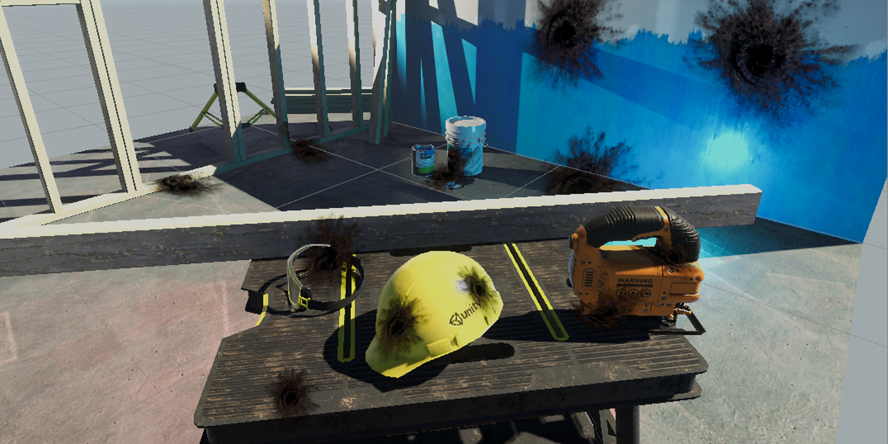
GitHub
Unity unlit screen space decal shader for URP. Just create a new material using this shader, then assign it to a new unity cube GameObject = DONE, now you have unlit decal working in URP - ColinLeu...
I would search online but I don't know what to search for
oh @grand jolt you are correct for setup with texture channel as smoothness, you could add a divide and a value to control the level. but otherwise I think your setup was correct
How would that look hooked up?
I'm not sure how to "add" them, because putting stuff in-between changes nothing in the inspector after saving the shader
if you add properties to the graph, check that the material has a suitable value as they don't always update if you change default.
damn that sounds odd but hopefully you will understand 😄
hhhh this is scary XD Why can't all node editors be easy like Blender, aaaaa
@civic jolt for the decal shader, I use that one myself now since it's only one working on newer version of unity urp.
The "mesh" it's attached to I believe is just defining the clip / display area, so you could work around that I think
Yeah I will write a DrawMeshInstanced thingie to draw cubes from entities if I can't adapt the shader
Also unlit URP shader is better at zmasking than lit shader -_-
Unlit
Lit
That's SSAO coming through behind it
Okiii I'm learning how it works. I finally figured out how to add a float value to change the texture value output like you said. I have like 0 experience with Shadergraph, so I'm learning ^^
give it a week then you will be teaching me 😄
@civic jolt damn that difference is huge, means writing your own lighting I guess into the shaders.. yet more time spent
The most painful thing is making a shadergraph, converting it to code, finding the culprit and then fixing it
That is if you can even fix it
And then fix it every time you change your shader
yea 😦 and then they update URP meaning new fix needed
Hah indeed
@thick fulcrum Have you found a way to turn off the AO effect in the planar reflection?
if I understand correctly, you need to define a second renderer which does not have the SSAO assigned to it. in your URP Asset you add this to the "renderer list", then in the planarreflections.cs code. Where it defines the camera (it creates on on the fly so to speak CreateMirrorObjects()), you need to tell it to use that "renderer". Assuming you have default and the one you created, it should be... ah
cameraData.SetRenderer(1); already exists, I think that's what is needed so you should just need to create a new renderer and add to list
@thick fulcrum That makes perfect sense. Thank you.
I want to make a dissolve effect, but based on overlap. It'll be a door of sorts and the parts where the character makes contact with it will seem to be dissolving into particles or something, and when past the door it'll be completely transparent. That latter I think I can do with a world position and a parameter which gives a normal for the quad/plane/whatever. The first part I'm not sure about.
I could use the distance from the parameter to decide if something should be happening, but I'm not sure how to displace "randomly" to make it look like bits and pieces (flakes? idk the right word for it) of the character are being sucked in
I've not messed around with that sort of effect, but I believe most just use a "noise texture" of some description. 🤔 not sure if that would work in this use case though
I suppose I could use noise for alpha
And if transparency doesn't look nice I can round it to 0/1
Not a bad idea... Thanks 😄
Can I also ask for feedback on effects I made?
Idk if this is the right place for it
@thick fulcrum What I did that seemed to work was making a second Forward Renderer with no AO, and then setting that one as default. Then I set the original Forward Renderer manually for the player camera. Seems to work. ^^
it's probably good a place as any if it's technical critique your after
Looks like the AO no longer shows up in the planar reflections
so long as it works ^^
Ye, I figured this might be an easier fix for anyone else wondering about it. Having AO in the reflections is both useless and performance hungry.
Now it's flying
Hm well.. I'm an amateur just trying to have some fun. I made an effect which I think looks cool. But I also know I have no prior experience so there's likely some stuff that can be improved that I'm simply not seeing.
no good asking me for any critique of a technical nature, I'm just a noob in training...
if it looks pretty, achieves what you want in a reasonably performant manner.. it's good enough for me 😄
The 1080p version of the video doesn't do it justice... Waiting for youtube to process it :p
Upside is that I had time to add captions.

I'm really bad with lighting... That's one thing I can see wrong with this
@thick fulcrum Do you think there's any ways to improve the performance for this by lowering the clipping distance or something for the planar reflection?
I'm not sure how to pull it off.. I get 60 FPS otherwise, but it lowers to 30 fps as soon as I look down.
@grand jolt in the planarreflections.cs file you could try adding to function CreateMirrorObjects() near bottom just after reflectionCamera.enabled = false; try adding reflectionCamera.farClipPlane = 200; or some other value.
I was messing the the downsampling earlier to see if that improved fps, but I didn't see any change... it's one of the things I'd like to look into improve myself. it's just on back burner with everything else 😄
simple fix.. get a better graphics card 😆
My graphics card is pretty decent tho. I just like to optimize things as best as I can. ^^
what gpu you have doesn't really matter if you are serious about gamedev
what matters is that it does work with the computer spec you want to target
ye
(of course in ideal case you'd have the min spec rig too)
Btw the culling distance thing doesn't seem to have any effect, unfortunately.
This seems like a stupid question most likely, but how do I expand these???
They changed it so you click the property then look at the graph's "inspector" window now.
OH, thank you lolol
@grand jolt the only other things I can think of which are quick and dirty would be to have it not render every frame, but a delayed update. this would cause some tearing perhaps though on extreme movements.
unfortunately as it is literally rendering everything twice, it's a costly effect.
if you only have some area's which use this, could perhaps save performance by switching it off. Put up some trigger box's near where you want it on and work it that way perhaps
Hmm idunno
I wish box projection was in URP right now for reflection probes
I'd just use that if that were the case
@grand jolt the resolution multiplier does make a difference, seems you have to disable and enable it to see the change as it's only sent to camera on creation. Also you might want to make sure the reflected surface is excluded from the "reflected layers" list as this could also cause some unwanted fps drop.
Good idea
Also my computer keeps crashing so I can't always respond back right away XD
tbh I don't know how you manage with the Unity beta, it crashes when I open it due to a GUI issue which got fixed in 2020.1 but still exists in the beta 😆
I'm wondering if I can set the planar reflections to FixedUpdate somehow
Any ideas?
It's using "UpdateCamera" and "UpdateReflectionCamera" so idunno
Hey,
I am trying to create kind of triplanar shader(every face would have color based on word position, like top would be green front red etc). I can get these faces from normal vector node + dot product. But When I try to combine left and right side together with add, the colors are different. Any help here ?
I think what's happening is that the dot product also returns negative values in the black area
The dot product result has negative values, so you'd need to Saturate before adding
Ah thats right, didnt count on that... 😄 That should be it. Thanks
Also you could just Split the normal vector and take each axis instead of a dot product. I think that would be the same result?
Hm, thats interesting. Should work. Will try. thanks @regal stag
Is it possible to get the total light intensity with the shader graph. I’m trying to use the total light intensity with saturation to greyscale things not in large amount of light
you need a custom fuction node for that (a bit of a pain, at least for me)
I thought so but I don’t know where to start with the custom node
I guess try to look up a cel shading tutorial on yt and see how they access the light values, thats what I always try to do, but stupid me uses the preview packages and it never works or I get tired of wonky mechanics and errors
Alright, thanks for the help!
Can someone explain me how SRP Batcher works ? I got Shader Graph material that is SRP batcher compatible. I have enabled GPU instancing and SRP batching in URP asset. When I have SRP batching enabled I got about 847 batches and saved by batching is - 842. So that's 5 draw calls right?(never seen - before saved by batching) The verts is about 6.5k. In frame debugger i seen 5 SRP batches. the reason for not being batches is srp first call from scriptable render loop job
Without SRP batching enabled 9 batches and saved by batching is 838. verts is 26.5k. In frame debugger with disabled SRP batching I got 4 Draw instanced mesh calls there is no reason why this wasn't draw in one call.
In this particular case the speed is exact but All the meshes in the scene uses same material, so I don't understand why the batches in stats window are so weird and why its not batched all in one call
How do I setup normal and specular maps in Shader Graph?
Is
c=lerp(a,b,condition)
faster than
if(condition)
  c=b;
else
  c=a;
AFAIK the first one should create 0 branches. Is the hlsl compiler smart enough to optimize the second one into a branchless version?
I've seen lerp used often instead of if statements in shaders but I can't find a lot of information online about this optimization
@dense thunder Sample the maps with a texture sample, and output the value to the master node
@fair sleet You could also do c=(condition)?b:a;
But in this case I don't think that a branch would be so costly. Depends on the whole context of how a and b are calculated
I think you missed a ?
if instead of a and b I have some complex calculation that takes,as an example, 30 cycles to compute. Would if or lerp be faster?
I don't think you can make any assumption, because it varies based on what compiler is used on what graphics library on what hardware
But I've heard many talk about how branching is not as expensive as we've often heard
Not on modern hardware, anyway
So the answer should be "do not worry about it"?
I think it also depends on the condition as not all if statements / conditionals will produce a branch, (at least from what I've heard. I feel there's a lot of misinformation about this stuff though, so not really sure).
There's a bit of info in the comments of this thread about this sort of stuff, might help : https://twitter.com/bgolus/status/1235254923819802626
@amber saffron I've got them working more or less. Texture 2D input set to Normal > Sample Texture 2D > Normal Strength > Normal PBR Master.
Similar for the specular/roughness map. Texture 2D input > Sample Texture 2D > Smoothness PBR Master.
The normals are working fine but the specular seems inverted. Whack an invert node on maybe?
smoothness = 1-roughness
Never mind they seem to be working alright now
Organization question! I've a graph that's my "main" shader. It's made with a bunch of subnodes already and it's pretty big. I'd like to have a version that allows for a texture.
-Turning the main shader into a subnode itself feels kind of off.
-Putting the texture directly on the main graph would create unneeded costs, even if the texture field is empty, I think?
-Copying the graph and appending the texture changes. In that case, if I ever changed the main shader, I'd need to go change it in there as well.
I'm leaning towards turning the main thing into a subgraph, but hoping one of you has an alternative that I don't know about.
@amber saffron Got another question... Is there a way to add a strength vector to the specular?
Why not simply multiply by a float value ? 🙂
@undone brook You can add a texture input and sample, with a keyword toggle branch
@dense thunder smoothness * value
@amber saffron I'm not familiar with what you mean when you say keyword toggle branch. Can you elaborate just a tiny bit please?
Ah, like add a bool and check against the bool to see if it should consider the texture?
yep
@undone brook
But the keyword (it's a specific section at the bottom of the input type list in the blackboard) does compilation branching instead of dynamic
@amber saffron This is very cool stuff. Thank you.
Reading through the API to make sense of keywords, I'm not understanding the "Scope" very well
I figured global implied that all the shaders using that keyword would share the same value. I think I'm deeply misunderstanding this.
Thing more as where the keyword is registered
For each keyword, a potential variant of the shader is created.
And to "identify" those variants, the keyword is store is a bit array, to make a mask.
There is a limited number of bits for the global keywords, and an other one for the local ones
global keywords can be shared between multiple shaders, while local one are specific for a shader
@amber saffron Thank you so much! One last tiny question, does the editor expose anywhere the amount of global keywords in use?