#archived-shaders
1 messages · Page 176 of 1
@sly breach i can see surf i for the fragment part, but i dont see how to access vertex attributes for a vertex shader
would i add this?
huh it got removed what
not sure why but my code seems to be getting removed
so I implemented a compute shader (the fractals on the left) it looks a bit better and I got a slight increase in speed. perhaps Im not using them right because people claimed the speeds would be much better
in here lies my problem and question.
result += fixed4(texCUBE(_ReflectionCube, normal).rgb * _EnvReflectionIntensity * _ReflectionIntensity, 0);
doesnt work in my computeShader
had to change it to
result += float4(texCUBE(_ReflectionCube, normal, id, id).rgb * _EnvReflectionIntensity * _ReflectionIntensity, 0);
but it's giving weird results it adds a outline instead of reflecting my cubeMap off the shapes I draw
I have a shader I'm trying to modify. I want anything Black to be transparent instead.
It doesn't use textures it's a compute shader (I think?) it generates a cool grid, though, but I want only the lines, and the Black background to be transparent
I don't even know what to look for in google, all they give me is the whole thing's transparency or textures alphas.
Here's the code if some of you want to look at it: https://hatebin.com/shcdhckzjo
Hey guys! I have a CurvedWorld unlit map. Currently it doesn’t support lightmaps. Does anyone know how to add that support through shader script? Thanks!
Here is the shader: Shader "Unlit/CurvedWorld" { Properties { _MainTex ("Base (RGB)", 2D) = "white" {} _QOffset ("Offset", Vector) = (0,0,0,0) _Dist ("Distance", Float) = 100.0 _Alpha ("Alpha", Range(0.0,1.0)) = 1.0 } SubShader { Tags {"Queue"="Transparent" "IgnoreProjector"="True" "RenderType"="Transparent"} LOD 100 ZWrite On Blend SrcAlpha OneMinusSrcAlpha Pass { Lighting Off CGPROGRAM #pragma vertex vert #pragma fragment frag #include "UnityCG.cginc" sampler2D _MainTex; float4 _QOffset; float _Dist; float _Alpha; uniform float4 _MainTex_ST; struct v2f { float4 pos : SV_POSITION; float2 uv : TEXCOORD0; }; v2f vert (appdata_base v) { v2f o; float4 vPos = mul (UNITY_MATRIX_MV, v.vertex); float zOff = vPos.z/_Dist; vPos += _QOffset*zOff*zOff; o.pos = mul (UNITY_MATRIX_P, vPos); o.uv = TRANSFORM_TEX(v.texcoord, _MainTex); return o; } half4 frag (v2f i) : COLOR { return tex2D(_MainTex, i.uv) * float4(1,1,1,_Alpha); } ENDCG } } FallBack "Curved/Unlit Texture Alpha" }
Anyone has used the Custom Render Texture?
I can't get it to update
It just initializes
anyone know why i am getting all black patches?
    half NdotL = saturate(dot(normalWS, lightDirectionWS));
    half3 radiance = lightColor * (lightAttenuation * NdotL);

    float3 hsl = RGBtoHSL(radiance);
    float3 hslToon = float3(0,0,0);
    hslToon[0] = hsl[0];
    hslToon[1] = hsl[1];
    hslToon[2] = hsl[2];
    float3 radianceToon = HSLtoRGB(hslToon);
    return DirectBDRF(brdfData, normalWS, lightDirectionWS, viewDirectionWS) * radianceToon;
    return DirectBDRF(brdfData, normalWS, lightDirectionWS, viewDirectionWS) * radiance;
this should do nothing as it converts RGB to HSL and back to RGB, but it creates black blotch where 1 light dont get to
using this RGB to HSL converter
yeah, I was thinking negative numbers as well
did not fix it
an, it was out of bounds values after all
    hslToon[0] = saturate(hsl[0]);
    hslToon[1] = saturate(hsl[1]);
    hslToon[2] = saturate(hsl[2]);
worked, thanks
@gloomy cairn you using URP?
theres a bug with render Textures on urp need to use Update not OnRender or w.e
I'm using HDRP. Just got it to work. I was doing a depth buffer with stencil (the default) when I needed to use No depth buffer (since I was just doing texture stuff)
Thanks for trying
Not too sure why it wouldn't update tho
It was kinda weird because any update that directly affected the Custom Render Texture (ie clicking on the check for Double Buffer) would make it work
ah nice. I was trying to get a raymarcher working in HDRP but for some reason the camera matrix was different on it. everything printed out distrorted . it worked for me in URP but I had to use a RenderTexture and Quad because rendertextures were busted
I was looking through the Frame Debugger and it was running the Update shader, but the output was still the Initialize Shader
I'm still confused over why turning off the depth buffer worked haha
weird cameras/windows popped up for me in the scene which should have been what showed up on my screen
XD
yeah im new to all this stuff as well
and all these fancy updates make it a bit harder
Hello I have an emission mask that is creating the red light as shown in the image. What would I use to scale the mask up so it covers more of the surface area using shader graph?
Scale up as in cover more space in the texture?
Yes, hopefully that is the correct term.
I want to animate it so it starts from nothing then covers the texture
While scaling equally in all directions
you're prob gonna need to rescale your incoming UV
What node would be used for that? This is my first shader, so I'm very inexperienced.
Uh so i'm drawing from my glsl knowledge here, not exactly shader graph. But you want to take your UV in your fragment and remap it.
Does anyone know what is 'required' to be put into the Input struct of a custom terrain shader? I need to do custom Input stuff, but nothing anywhere has like any information on this. I've been banging my head around this for like 12 hours straight and just can't figure it out.
    };

        void surf(Input IN, inout SurfaceOutput o)
    {
        half4 splat_control;
        half weight;
        fixed4 mixedDiffuse;
        SplatmapMix(IN, splat_control, weight, mixedDiffuse, o.Normal);
        o.Albedo = mixedDiffuse.rgb;
        o.Alpha = weight;
}```I don't think I understand. Could you try perhaps explaining it a bit different? Thank you for your time.
@empty bridge You can try something similar to what I did a while go, not sure if its the result you want. But you make 4 tiling and offset nodes to represent your 4 cardinal directions. Then you input into their offset the cardinal direction with a small magnitude ([0,0.1],[0,-0.1],[0.1,0],[-0.1,0]). After that you sample their texture with the magnitude UV, then multiply the results all together.
Or you can just make a bigger texture in photoshop or GIMP
The goal is to dynamically adjust the size of the emission
I'll try what you just suggested.
ngl its one of those things that look better in code, but looks horrendous in a node-system
I‘m currently writing a deferred shader for Vulken, but I‘m running into a problem.
Line 63 produces this error:
‘frag‘: Not all control paths return a value
There are no ifs or other control structures in the file, so what am I missing?
I just figured it out, I forgot to return the output struct 🤪
@prime pasture Hey, I tried making a shader that writes to SV_Depth. This one kinda works. It's a modified Skybox/Cubemap shader that takes in a depth cubemap.
https://hatebin.com/qvwbpitawu
You might want to add in a multiplier to control the range of the depth map
This shader isn't perfect, like changing the far clip plane messes with it
@low lichen I tried the same thing yesterday, maybe I missed something, gonna try again and compare your shader you mine! thanks!
Most important thing is to enable ZWrite
@low lichen Yeah I figured its not a perfect method but it should do for my case
Yeah I did that
I just saw something about DrawSkyboxPass, in the docs it says its a skybox pass and there is an option to provide a depth buffer
didn't get to finding more about it but first I want to try the method you gave again
I looked it up. That's just for making sure the skybox stays behind other objects. You give it the depth buffer it should test against.
Yeah I thought maybe I could modify the depth buffer with the mask but that's essentially the same as the shader you gave above
The shader method should be faster even
@low lichen I tried it again but with no luck, I am looking at the Frame Debugger and the Depth buffer doesn't change on the skybox render
I use 6 faces for the cube map so I edited the "Skybox/6 Sided" shader
Ops, the line:
output.depth = 10.0;
is there just for testing, ignore it
Actually, looking at it now, The frame debugger doesn't use my textures...
no
there should be two textures there in the Textures part
_RightTex + _RightTexMask
weird...
Never mind... its because of the line I have put in
output.depth = 10.0;
the texture got optimized away
You can see there are parts in the _mask that has 0 and 1 for the mask
The depth buffer remain unchanged
Returned the depth as color, no luck, just no skybox and depth buffer has no affect
Could be wrong but I'd check the FragOut frag(v2f i) : SV_Target lines. I only see SV_Target there so it might be ignoring the depth one?
Ah, yep, that could do it
I come from OpenGL actually so I am not actually sure how to add SV_Depth(?) to it, do I just add a comma and SV_Depth?
On @low lichen shader there is no SV_*, is there a reason for it? there is a default?
The semantics are already attached in the FragOut. So it should just be FragOut frag(v2f i).. I think? I haven't really done any depth output shaders before.
@regal stag Tried that, no change to the depth buffer :\
So the output is not going to the depth buffer at all, even if I hardcode a value to it
There is this things:
https://docs.unity3d.com/Manual/SL-DepthTextures.html
But I didn't find anyone using it for writing, and I don't really understand how to actually write to it

You always have a depth buffer if you want things do be able to occlude others
I guess I could reverse UNITY_OUTPUT_DEPTH to figure out how they are writing to ti
The depth texture is a bit different from the actual depth buffer used for z-testing
Oh
So this depth buffer is not used for the same things as the z-depth buffer (the internal one lets call it)?
This page is kinda confusing honestly. It's kinda referring to a depth prepass
Yeah...
Ok so I'll keep trying to figure out why its not writing to my depth buffer..
Maybe its something to do with me using the new pipeline? (LWRP)
I tested the shader I gave you on URP
Are you able to share the textures you're working with so I can test your shader myself?
Got it!!!!
output.depth /= i.screenPos.w; This line was the problem, I don't know if screenPos has wrong values but I need to change it so I switch from really near or really far in the depth based on the mask
Are you testing it in the scene view?
No, game view
Like I said, the far clipping plane has an effect on it, so I had to disable dynamic clipping planes on the scene view and set it to something like 1000
Your shader works for me, with the output.depth /= i.screenPos.w; line
I had a panorama from Google Street view with a depth map
So I just used that on all the faces
Ok, maybe its my masks then, I didn't check them just got them from the designer
Looking at the Frame Debugger now.. My cars using Universal Render Pipeline/Lit shader, it doesn't seem to write them to the depth..
I guess putting a plane behind them will show them
I am really rusty I guess, shouldn't this work?
(The depth buffer still has nothing)
Can you take a screenshot of the depth buffer?
Are you sure it's just not really faint, as Mentally mentioned
There's a Levels slider on the frame debugger that should help a bit
But you usually have to drag it all the way to the start to even begin to see anything
So that's what the output.depth /= i.screenPos.w is for, to convert the depth from linear to non-linear
I think maybe the masks are wrong, I'll try to export them from photoshop and look at it
anyone know of a way to check if any one of a number of bools are true in shader graph?
There's an OR logic node to check multiple bools
aha, thanks!
output.depth = tex2D(mask, i.texcoord);
//output.depth = 1.0 - output.depth;
output.depth /= i.screenPos.w;
output.depth *= 1900.0;
I had to multiply the depth value by ~1900 to get to the right depth values, I need to read up on the depth buffer again I forgot a lot of stuff
"How do I apply to post process effect to only one camera that renders after others?"
I found this answer where multiple cameras render to a single render texture. But since I have 7 layers, I'd need 7 cameras. Is there a better way?
https://www.reddit.com/r/Unity3D/comments/deh3fd/how_do_i_apply_to_post_process_effect_to_only_one/
reddit
2 votes and 2 comments so far on Reddit
Where do these 7 layers come from?
What do you need that many layers for? And why specifically 7?
Cause when I speak to a character, a text dialogue comes up with their avatar. Their avatar is made up of several images (hair - wobble animated using shader), body, eyes, etc - this avatar would have one Post processing effect come up, but I don't want the post processing to effect the layers behind it.
I want this character to render above the text dialogue box, but I don't want the text dialogue box to be affected either. I want to apply my own effect on the text dialogue box and not the ones behind the text (e.g. the Main Camera).
I have a UI health bar, which the "character's avatar" renders on top, but I don't want any effect on it.
I then extra cameras/layers where I script post-processing (e.g. animate/tween chromatic abberation or lens distortion), but I cannot share the layer because I want to keep the default chromatic abberation always on etc
I'll try the render texture strategy with 3 cameras and try reduce the number of cameras. I haven't worked on this problem a lot due to busy/work but I've been thinking about it in the background for a few weeks. Otherwise I'll look at stencils on cameras (no experience yet but will research)
there were like several different solutions but none are simple
If the post processing effect doesn't rely on sampling neigbouring pixels, then you could use stencils to mark which pixels should get what effect
But chromatic aberration and lens distortion both sample neighbors, so it wouldn't be possible with those
Well, you could, but it would look weird
Oh I see. I'll quickly see what it looks like to learn.
With stencils, how do I apply them?
Can I apply it on the Camera component? Or do I need to apply a material to every sprite?
so I'd need my own custom chromatic abberation shader with the stencil solution?
Are you using URP by any chance?
you're right it looks bad. Uh no but I can switch to it
I didn't use URP cause the chromatic abberation in URP looks different to my post processing v2 chromatic abberation (it had blurs in)
but willing to switch (and a few other reasons)
since URP looks good and i used it for about 30min to see how it is
The render texture solution is also not good because there's a "flash" or delay when it completely switches/changes the image
@low lichen @regal stag Thank you I found a solution!:
output.depth = 1.0 - LinearEyeDepth(tex2D(mask, i.texcoord));
I wonder if my stencils would intefere with existing shaders, but I will look into it. The stencil solution seems to be my last hope T_T
I'l read this post https://forum.unity.com/threads/leveraging-stencil-buffers-for-masked-post-effects.313466/, it looks like it'l ltake some time hehe
does the URP PBR shader graph have fog automatically? or do i have to implement it myself?
nvm, guess it does
it's really bugging out on my large objects
Are you using URP by any chance?
@low lichen Stencils might be a bit hard cause I'll lose "info" behind the image, so if I post-process a "wobble" effect, it might not work. But I guess ShaderGraph is the only solution left? I'll learn more about stencils anyway and I might have to modify/create my own chromatic abberation shader to take into account certain stencils (I am a big noob so I will still learn both solutions)
I'll do shadergraph, it seems the best way
@low lichen So i found out that no normals are being created. I checked the count for normals and its 0.
I discovered the problem. I think I'm onto something, @fast skiff said to use Recalculate normals. That sets them properly. So I'll see what I can do.
LOL, that was literally it. No more than **RecalculateNormals(); **Thanks @fast skiff and @low lichen for the generous help.
Is camouflage possible with the shader graph?
@true steppe wdym camoflauge? Transparency? Blur?
like military style camouflage
im not good with shaders at all sorry
Is this type of thing possible without textures?
I do have a new issue though. Why aren't real-time shadows falling onto my made-from-scratch mesh faces? Thanks.
@true steppe yes, use some noise functions together with step functions and then overlay them with different colors (green, brown, black, whateverà
some gradient noise could look decent
I tried making something, shaders are complicated 😦
what kind of shader should I use?
What am I doing wrong?
Ok more like what am I not doing wrong, I am NOT good with shaders at all.
no, put the gradient noise into the step
the gradient noise node basically outputs a value between 0 and 1, and transitions are smooth. but in your camouflage, the patterns have a hard cutoff right?
so you use a step function
a step function takes an input, and if the input is above a threshold, the output is 1
otherwise the output is 0
Right
so try putting the output of the gradient noise into the input of the step node
and then put a [0-1] slider into the 'edge' slot of that step node
then you'll see what's happening
We are in the right direction, thanks! And how do I actually add colors now?
well what I do usually is put the output of that stepped noise into a lerp function
and then lerp between 2 colors
I will try that out...
you could lerp between A: green and B: brown for example
Ahaa
that will convert the output image you currently have, to something where all the black parts are green and all the white parts are brown
so using 'green' as your 'background color' here basically, and then the brown is added pattern
yeah so now you have green + brown right?
I am using black and dark gray
I would use another gradient noise + step node
and then lerp between your current output, and that
so basically adding a new color
also, if you want to change the scale of the pattern, use a 'tiling and offset' node and plug that into the UV input slot of those gradient noises
Hey guys, i am wanting to create a grid that i can apply to a plain and the squares be highlighted/ then later put spawn gameobjects at the squares i click on. ANY idea if this is possible via a shader
@cunning heart there is a 'grid' pattern that comes with the shadergraph sample package I think
and then do the click detection in C#, detect mouse position
Its not adding red? Why?
There doesn't have to be any real connection between the shader and the grid logic in C#
Sorry to interrupt!
@true steppe those gradient noises have exact same scale and step threshold so are exactly one top of eachother
Woops!
@high hemlock I hadn't thought to use RecalculateNormals, but I think it's pretty clear why your print was giving you 0, because you haven't assigned the normals array there yet.
You would create a Vector3 array, fill it with your data, then set mesh.normals = theArrayYouCreated;
In your case, you just did mesh.normals[i] = //whatever
I applied the material to this gun, its all white?
@devout quarry if i am using the grid as a snap to grid surly there has to be more logic
@cunning heart yeah but you can just do all the grid logic in C# right? and when you decide for a tile-size in C#, just use that same tile size for your visual grid so that visuals + logic matches
I was hoping that i didnt need to do the logic c#wise as originally i did it with gameobjects but i ended up with 400 game objects
Uhmm hate to interrupt, but my material is white in scene!
how do I get the Post Processing v2 Chromatic Abberation? It doesn't look the same as the integrated Chromatic Abberation (I don't wanna use v2 cus it'll get deprecated)? Is the only way is to implement my own shader?
It looks like they blur the edges
Hmmm, I guess maybe I can make my own vignette blur shader and combine it with the integrated Chromatic Abberation. The difference between them is that v2 chromatic abberation sorta "blurs" it, looks a bit like a zoom blur or something but I'll try replicate it
How do I make this seamless? (How do I get rid of that line in middle of the preview)
How do I apply my own shader to a particular shader graph node?
Shader Graph is pretty cool
You can create Custom Functions
Which can either have shader functions in them or reference a cginc file.
thanks and how do I combine two layers together, which node do i use for that
e.g. A "hair" sprite in front of a head
i am new to SG
There's a Blend node
I saw but I wasn't sure which blend option
does anyone know how to get multiple lights working with shader graph?
I'm outputting to Unlit
with no blend option
as in
I overwrite it
is overwrite the right one? It bugged but I'll double-check
I don't want multiply or overlay etc
I want the second one to take priority over the first image
You mean as if the hair is a transparent quad that is on top of the rest?
That can be done by lerping between the two, using the alpha of the hair as the T value
And the hair as the B input
Then, if the alpha of the hair is 1, it will use the hair. If it's 0, it will use A
But there's a blend where they overlap
but no overlay/multiply thing
Then, if the alpha of the hair is 1, it will use the hair. If it's 0, it will use A
@low lichen yea
if hair alpha 0.5, it'll use 0.5 of the other image
if hair alpha 1, it'll only use hair
the most default blending
Right, so the Lerp node
@brittle owl Your problem is probably specific to URP, because HDRP and URP and built-in all do lighting their own way
So I lerp the 2nd image's Alpha? I just did that but how do i convert Out(4) to RGB(3) + Alpha(1)
The Lerp's output is (4)
A would be the color behind the hair
B is the color of the hair
T is the alpha of the hair
The output is the blended output
exactly
how do i do this is what i mean.
The output of the Lerp node is Out(4)
can I just do that or do i need another node to separate Out(4) into two more outputs
Pretty sure it would just use the first channel, red, for the alpha
So you'd have to split and connect the alpha to alpha
But the first connection can be the same
Ah the Split node
thanks got it, genius!
Yeah it works, thanks a lot
First time really using Shader Graph, I will use ShaderGraph solution instead of trying to post-process 7 layers that I've tried to solve for weeks
seems really nice, hoping to try out some of the scripting methods of ShaderGraph later when i ramp up
It's been interesting experience converting my project to URP
yeah i made a toon shader in shader graph for urp that calculates lighting based on a custom node that outputs the main light direction/color/attenuation and stuff, but I'm tryna figure out how to get it to also get lit by point lights and such
its unlit
any one know how?
Pretty sure you need a custom function for that
There's no node for getting additional lights
There's probably a function somewhere in URP's shader library
https://github.com/Unity-Technologies/Graphics would be the place to look for it

GitHub
Unity Graphics - Including Scriptable Render Pipeline - Unity-Technologies/Graphics
ill check it out, thanks!
There appears to be a couple of GetAdditionalLight functions
Also appears to be a GetAdditionalLightsCount function
So my guess is you would first get the count, then do a for loop in your custom function and call GetAdditionalLight with each index
Then you get this Light struct, which you can do whatever you want with.
struct Light
{
    half3   direction;
    half3   color;
    half    distanceAttenuation;
    half    shadowAttenuation;
};
You add one light at a time
But it's completely up to you
You can only get one light at a time, but if you want to merge them yourself in some custom way, you can do that
Normally, they would be blended additively
You're just getting raw data about what lights are close to the object
It's up to you what to do with it
hm
You need a custom function to get it
yeah
You could then output that in some format out of the custom function to do something with it in the graph
Or do most of the work in the function
ill look into it, ive never written any shaders before so this might be hard lol
is it possible to make a custom function in shader graph that directly references lighting.hlsl
Yes
o
So if I have about 7 images, I need many Lerps (because i need to keep combining them until they become 1). Is there a Lerp for a variable amount of layers? Or is this something "Custom Function" I have to make myself
whats the correct node i should look at or guide to make my own custom node that combines 7 images all at once in a single node, instead of having to have a massive shader graph
Cause if i have 8 images, i'd need 4 + 2 + 1 Lerps
A custom function seems like the right call for that many lerps to avoid spaghetti
thanks I'll study these
So this is in 2D?
yeah 2D game
UI images
cause I have hair, as separate image to body
i animate the hair using a "wobble" shader
and then I want to also wobble the entire combined image as a whole so the character doesn't look static, and maybe apply 1-2 other shaders
these images come up during dialogue conversations in game
And you need to be able to add these as separate layers because the characters are customizable?
I needed them to be separate layers to "shade" them differently
cause i might want to wobble the hair even more
than the whole character
i have a shader thats like a jelly
its a cheap way to animate the hair
and maybe i want to animate eyes hmm
But I don't understand why it's better to have this all in one shader as opposed to separate sprite renderers or something
How do I do it in one shader
so the hair wobbles
but i don't want to wobble the face
The hair changes position slightly
like wind
we can do separate sprite renderers, but i also want to apply a shader to the whole image
Wobble the hair before you blend it into the rest
yh i will be
oh yeah looks like the customLighting.hlsl file that my shader already uses has an additionallights function:
{
    half3 diffuseColor = 0;
    half3 specularColor = 0;

#ifndef SHADERGRAPH_PREVIEW
    Smoothness = exp2(10 * Smoothness + 1);
    WorldNormal = normalize(WorldNormal);
    WorldView = SafeNormalize(WorldView);
    int pixelLightCount = GetAdditionalLightsCount();
    for (int i = 0; i < pixelLightCount; ++i)
    {
        Light light = GetAdditionalLight(i, WorldPosition);
        half3 attenuatedLightColor = light.color * (light.distanceAttenuation * light.shadowAttenuation);
        diffuseColor += LightingLambert(attenuatedLightColor, light.direction, WorldNormal);
        specularColor += LightingSpecular(attenuatedLightColor, light.direction, WorldNormal, WorldView, half4(SpecColor, 0), Smoothness);
    }
#endif

    Diffuse = diffuseColor;
    Specular = specularColor;
}```but, im not sure what here is an input, and what here is an output
Every parameter that starts with out is the output
oh
also, it doesnt seem like it gives light direction/attenuation/color like my mainlight function does
Would you be doing something different with those values than to calculate the color of the light it contributes
After taking direction and attenuation and color into account?
oh all this gives me is the light color?
sorry im really confused lol, very new to this
It does give you the light direction, colour, distance atten and shadow atten, but it's inside the loop because there can be multiple additional lights (they are in the Light light variable). Rather than passing those out and handling the rest in the graph (like the N dot L / diffuse calculation), it's handled in the custom function instead, adding each diffuse and specular result together.
If you want something more custom, like toon shading, you probably need to look at replacing the LightingLambert and LightingSpecular functions with your own versions. Can see what they do in the URP shader library Lighting.hlsl.
But couldn't you toonify the colors too? Or is that not normally how you do it?
Add steps to the gradient
how do you make a drop down menu like this?
@cerulean thunder https://docs.unity3d.com/Manual/SL-CustomEditor.html
I am editing an existing shader, where do I find the custom editor code?
Is this it?
Search for CustomEditor there should be a name of the class (and should be the filename as well + .cs as an extension)
If the shader does use custom editor that is
ah, found it thank you @prime pasture
🙂
CustomEditor "UnityEditor.Rendering.Universal.ShaderGUI.LitShader"
now where can I find this code and make it my own? does not look like a path
ah, found it, thank you, it is in packages
@cerulean thunder You should probably create your own and modify the CustomEditor line with your path
so only that specific shader will use your custom editor and not the entire shaders that use LitShader
So, I'm following this Brackeys tutorial https://www.youtube.com/watch?v=NiOGWZXBg4Y, but when they get to the alpha pbr node it doesnt do anything for me

Let's learn how to make an awesome force field with Unity Shader Graph!
● Check out Skillshare! http://skl.sh/brackeys15
● Support us on Patreon: https://www.patreon.com/brackeys
● Project Files: https://github.com/Brackeys/Force-Field
● Water Shader shown in intro: https:...
Would using URP instead of LWRP mess things up?
I think URP is a new name for LWRP
Oh, I didn't know that lol
My apologies
another weird/cool thing that happens is when i use the main camera to look at the sphere i get a black on white silhouette of the scene view
@grand jolt You sure your shader output is set to transparent?
I believe that's in the settings of the master node
The master node, where everything connects to, should have a cog icon
okay so i tried out that custom function that i sent earlier
it outputs pure black
no matter what i do
im not sure what im doing wrong lol
@high hemlock glad, if i could help. For shadows on your objects: you have to set the receiveShadows property to true on the Mesh Renderer (either in the Unity editor or script), but this is more beginner stuff than shaders. (beginner-code maybe?)
ok, the custom GUI for the default lit shader is a bit advanced, how do I add a couple more values here?
probably like 2 sliders of 0 to 1
btw. which channel is suited for jobs & burst compiler stuff?
Hi, I'm back. I took a break and came back and changed the master node to transparent but the sphere looks super high contrasted
this is what it looks like
i managed to find this function online for grabbing lighting from additional lights
half3 MyCustomLightingFunction(Light light, half3 normalWS) {
    half dotNL = saturate(dot(normalWS, light.direction);
    return light.color * light.distanceAttenuation * light.shadowAttenuation * dotNL;
}

void AdditionalLights_half(float3 WorldPosition, half3 surfaceNormalInWorldSpace, out half3 additionLight)
{
    half3 lightingFromAdditionalLights = half3(0, 0, 0);
    int pixelLightCount = GetAdditionalLightsCount();
    for (int i = 0; i < pixelLightCount; ++i) {
        Light light = GetAdditionalLight(i, WorldPosition);
        lightingFromAdditionalLights += MyCustomLightingFunction(light, surfaceNormalInWorldSpace);
    }
    additionLight = lightingFromAdditionalLights;
}
but it gives me the error Unrecognized identifier 'Light'
in shader graph
I have loads of .shader files. Is there a way in Shader Graph to have a "Material" node, or apply an existing .shader file without porting it? I have about 20+ shaders, do I have to port them if I want to use it in ShaderGraph?
"Applying" a shader doesn't really make sense
Applying a material then
i have a material (which has my shader on it) and i would like to use it as a ShaderGraph node
is it possible to print the value of _Time.y over time to the console?
I think it's safe to assume it's the same as Time.time
I have this _RimWidth value in the shader, how do access it in HLSL?
you're right
@cerulean thunder You need to declare it in the global scope in HLSL. Like:
float _RimWidth;

fixed4 frag(whatever)
{
    return _RimWidth;
}
@low lichen Thank you so much
is there a way to set default values for these?
I have set them in the shader but it is getting ignored
hi guys, just trying to let people select which UV channel to use in the inspector, this is how it's set up, it's currently showing as an int input in the inspector though...any way to change it to a dropdown?
Ok i Have a bit of a problem, lets say i have a particular mesh, but i wanted to keep the main vertices of the mesh except some of the vertices closer to the edge of the mesh. Basically the closer the vert is to the edge of the mesh the more it becomes 'flat' or the amount i specified, leaving the center unaffected, as well as the height of the mesh that i was going to add as another parameter but it i cant seem to get it working properly. Im not sure why its not allowing me to subtract the 'mask' that ive made to allow it to only affect a particular region.
the edges of the mesh are like this in particular and im trying to make it flat for specific regions, namely the external sections
result += fixed4(texCUBE(_ReflectionCube, normal).rgb * _EnvReflectionIntensity * _ReflectionIntensity, 0);
can anyone help me with this, this line used to reflect my cubeMap onto the surfaces of objects but im using a compute shader now and it no longer works.
I changed it to this to get rid of error but its doesnt have same behavior most likely because its a different coordinate
result += float4(texCUBE(_ReflectionCube, normal, id, id).rgb * _EnvReflectionIntensity * _ReflectionIntensity, 0);
I just want to put the same material on two things and have them use different parameter values...why is this so hard? 😭
anyone have any idea how i can create and use a compute buffer that has a stride length of 2 bytes? I want to generate a 3d array of noise values which I work with as ushorts on the CPU
where can I get HLSL code for smooth noise/ perlin noise?
I need a function float smoothNoise(float x, float y)
found it, thanks
@wary stump I'm assuming that rectangle node is not compatible with vertex stage, can only be used in fragment stage
these two things will be better separated in future / are already done so in 10.x Shader Graph
that would be a firm no thank you, this also isn't the right channel for that
I literally know nothing about shaders, I'm putting that out first before asking the question. So I have a custom stencil shader in Unity's default shader how do I upgrade it to URP?
*Edit > Render Pipeline > URP > Upgrade doesn't work
I converted my project to URP.
One issue is there's no custom post processing yet, but there's "custom render passes", but the issue is I only want to affect stuff behind my "UI".
One workaround I just thought of is using a UI image stretched to the whole screen and applying a shader to it - will that approach work and does anyone have further pointers, since I have no idea? Should I convert back to HDRP until URP's features are done?
My game is a 2D game (PC)
i have a problem with some artifacts appearing in my clouds i made for URP (shader graph)
here is how it looks in game view
however it looks properly in the scene view
what am i doing wrong?
its just made up of stacking quads for simulating volume and height
with a cloud shader which uses 3d noise
thanks in advance
I'm trying to make a 2d fog shader, but it seems when it fades to transparent, it fades to black at the same time. Do I need to extract the alpha of the noise and use it separately?
It's just like this, time/offset nodes excluded
seems that the entire color is set to that
so create a vector4
and set everything to 1 except w
Yeah, instead of multiplying by the colour, split it and put the colour into the XYZ of Vector4, and noise into Alpha
hmm let me see
Same result here, should I add the color later?
(thanks for superquick reply btw!)¨
Aha, i think i know what you mean now
@golden glade Not sure what would be causing that (your clouds issue). Is it maybe some post processing that's only visible in the game view?
Don't multiply the colour and noise @west fulcrum
The multiply with the greyscale noise is what is darkening the colour. Multiplying by 0 for example results in black.
Hi everyone!
So I’m using shader graph to make a shader that permit inverting Colors of the objects we see behind.
For example, I’ve a window and I want to look through it, everything is normal, but through an other window, all colour is inverted.
I know how to invert colours, but how can I take the different part that is behind the window to change those colours?
Just split the Color property and put it into the Combine
Or, put the noise into the W of a Vector4 node, with XYZ as 1, and multiply that with the Color.
Thanks a lot @regal stag it worked 🙂
@limber flicker Maybe with the Scene Color node? It will only show opaque geometry though (at least in URP)
without the need of split and combine nodes
Yeah I try to avoid the split -> combine stuff as it gets messy
I saw some image where they had like groups around things, but I can't seem to find it. Was that in another shader editor?
like with a big label
You mean like this? Can highlight nodes and group them. Ctrl+G is the shortcut
@limber flicker Maybe with the Scene Color node? It will only show opaque geometry though (at least in URP)
@regal stag yeah I’ve tested...
Do you want multiple of these inverting-windows to be able to overlap?
Oh yeah, we'rd that i didn't see that. Exactly, thanks 😄
This is what I’m doing.
what is the best approach to create custom HDRP sky shader with Shader Graph ?
or HDRP skybox shader master node is still not a thing even now ?
@limber flicker For the Scene Color node to work the shader's Surface type needs to be transparent (cog on master node), and the Opaque Texture option on the URP asset needs to be enabled too.
@golden glade Not sure what would be causing that (your clouds issue). Is it maybe some post processing that's only visible in the game view?
@regal stag i disabled post processing and it still has that weird color thing
Is there an issue with using Sliders in the blackboard? Sometimes they show up as sliders, and something just regular text fields in the inspector.
Hey people! Shader baby / noob here! I've got a wiring system in my game that allows the user to drag wires to and from props. I'd like to have a material that shows a repeating arrow texture in the way the wire is pointing. It'll ideally scroll too, although I can manage that part. The problem is, I'd like the tiling to look the same from all angles and also stay the same regardless of the length of the wiring. Anyone know a quick solution to this in ShaderGraph?
That's an example of the desired effect. It's also worth mentioning that the wire width will never change, so I can hard code the values in. The length and direction will be variable though
a 2D sprite maybe?
with a sprite mask to limit the texture from starting-point to end-point.
It's used in a 3D context though :/ It's a line renderer between two cubes in the world
Oh if it's a line renderer there should be a setting on the component to make the uvs tile. (I think it's named texture mode?)
yea i think there is that option
@west fulcrum they only show up when there is enough 'room' for them to be displayed right?
@devout quarry aha maybe! I’ll try to make inspector wider:)
Thanks people! I'll report back in a minute
Shader properties can't be added to this global property sheet. Trying to add _GrabTexture_TexelSize (type 1 count 1)
UnityEngine.GUIUtility:ProcessEvent(Int32, IntPtr)
What's this mean? My project is broken and I don't know where. I tried exiting/re-opening
Shader properties can't be added to this global property sheet. Trying to add _GrabTexture_TexelSize (type 1 count 1)
UnityEngine.GUIUtility:ProcessEvent(Int32, IntPtr)
What's this mean? My project is broken and I don't know where. I tried exiting/re-opening
@rugged verge solved this by binary search "deleting" my Game Objects to see the culprit Game Object
Hey, does anyone know of a solid method for making an outline shader in shader graph? I've been trying to research it and can't quite find much that's helpful or good-looking. Any tips are appreciated!
i need some help lol 😅
i made a shader that does a gradient based on the height, for the walls
but when i start the game it changes color??
to this
It uses object space, and I assume your walls are statically batched
that will combine them
and change the coordinate space
Either don't use Object Position (use world instead), don't use static batching, or find another way to bake color/position into your objects (sometimes vertex color is appropriate)
Whatever works best for your project and situation really
I have heard there is a possible bug where static batching will also break vertex colors
how do i correctly add reflections to an unlit object?
currently, im just lerping the output of the reflection probe node with my shader, and it looks like it works, but when looking at the reflection in the object, it looks like the reflection is reflecting the wrong direction
and its rotated too??
idk
reflection probes are good for general things, but if you have a particularly flat surface they don't work. Where you might have a TV / mirror / shiny tile floor, it's better to use planar reflections if you want a good result.
using urp lol
Does anyone have an idea why my color property of my material with a custom shader changes color each time i enter play? If i set it to 255 on all values, it sets to 191 on all. If I set 255,191,191 it changes to 191, 144, 144. It's very confusing. There is no script modifying the material, the property just has a random name like Color_af7bC3e.
Is it possible to layer materials on a mesh? I have tried just making the material size of the mesh from 1 to 2 but that seems to cause problems
I am using standard Unity as well
@brittle owl sry been busy or would have linked you this earlier, URP is not an excuse 😉
planar reflections are very doable, ignore the fact it says "lwrp" it still works in URP I use a version of this myself.
https://github.com/UnityTechnologies/LWRPScriptableRenderPass_ExampleLibrary

GitHub
Contribute to UnityTechnologies/LWRPScriptableRenderPass_ExampleLibrary development by creating an account on GitHub.
@west fulcrum I suspect it's something to do with HDR color intensity greater than 1, does the shader use a hdr color or is it converting perhaps?
check settings in your shader graph
@thick fulcrum thanks, it might be the reason, but hdr colors should work, shouldnt it? I dont need hdr for this though. Thanks 🙂
Hello, is it possible to paint over a texture using a shader? I would like to paint color and brushes (think 2d painting app for kids)
I tried using SetPixels but it is way too slow :/
Anyone successfully used the Ambient node in Shadergraph in their shaders? It just seems so broken, It will only show the correct ambient light color when I save the shader in Shadergraph - updating the Lightning settings afterwards and saving scene, and/or entering playmode the ambient light is just set to black.
Guess ill avoid using it for now and use a Shader.SetGlobalColor
I think I recall seeing a mention of a bug fix with ambient values not being initialised correctly in the URP v10 changelog.
But yeah, for older versions probably should use SetGlobalColor or something
Thanks @regal stag I did see multiple users complaining it did not work sometimes depending on platform (iOS) could be that all of them was on same version of URP - but yeah it feels risky to use.
I am on newest 7.5.1 of URP, what version number is v10 from?
I'm not sure if v10 versions are in the package manager yet or not. They would likely only be available for the most up-to-date unity betas though
aha, I see - thanks.
How can I get a camera's view porjection matrix in URP shader? I have a _CameraViewProjMatrix variable in HDRP but not in URP.
UNITY_MATRIX_VP maybe?
hi! I was just looking at your URP article, btw 🙂
I think I have to get something else, actually, since even a shadergraph's source file issues something like that
Bingo! UnityInput.hlsl features a _ViewProjMatrix
I think I have to use that.
or maybe your're right...
@crystal light what are you using the View Projection Matrix for? I am currently struggling with a RenderTexture not rendering what the camera actually sees. I think I remember something about an issue with projection matrix when using RenderTextures.
In my case i have a Monitor mesh, with a plane almost overlapping it with a custom shader. The Monitor mesh is rendered in the RenderTexture but not my plane/custom shader. If I hide the Monitor mesh, the plane is actually rendered. So this sounds like Zcull fighting not rendering correctly into RenderTexture or something.. hm
ah, nvm - it was actually an issue with the depth buffer.
Hi guys, i'm currently trying to set up a Coat Mask in Shader Graph like HDRP Lit shaders have, I was wondering which channel I need to output?, I imagine the attenuate coat effect just multiplies the value so i've set that up too
Trying to replicate this:
@crystal light what are you using the View Projection Matrix for? I am currently struggling with a RenderTexture not rendering what the camera actually sees. I think I remember something about an issue with projection matrix when using RenderTextures.
@faint notch I'm trying to implement a distance-based tessellation.
ah, nvm - it was actually an issue with the depth buffer.
@faint notch glad you solved it. shader issues can be tedious to debug
I always forget something trivial to use.
@west fulcrum is your fog receiving ambient lighting from the scene? (I don't think that would change the color property's RGB values but) I thought checking the lighting window was worth mentioning
@low lichen Hope your proud, lol, went from 300 lines to 40.
Better, but damn that's a lot of game objects and get components
And that's just for spawning one block
Hi, I am trying to get my greenscreened video without background. I removed the green screen in Premiere Pro but I dont know how to remove it in Unity, it starts with a black area. I applied a transparent background to make the cube area smaller but it doesn't fix the problem. Does anyone know how I can fix this? Thanks in advance
@karmic tusk I think it should be possible to layer materials on a mesh somehow with a custom shader, but I don't know much about those yet.
I only can tell you that the Material Size on a Mesh-Render you can set to more then 1 is used for submeshes. As the Reference guide is a bit spongy about this topic, I found a simple example that explains the use very well: https://answers.unity.com/questions/1436857/small-submesh-example.html
Unity is the ultimate game development platform. Use Unity to build high-quality 3D and 2D games, deploy them across mobile, desktop, VR/AR, consoles or the Web, and connect with loyal and enthusiastic players and customers.
this guide helped me to use submeshes correctly for my code-generated mesh. It is quite easy and straightforward, but I don't know, if it helps you @karmic tusk as you can only have different materials on different triangles. Not per vertex and no blending of materials.
Therefor you will need some kind of shader. (i mean blending and a material per vertex)
PS: You could search for a Texture Splatting shader, that should do it. But I have no idea of it yet, would like to implement something like that myself at a later stage (or later date).
As well as triplanar mapping, that is is even more important to my project.
@topaz oriole what file format do you use? mp4-s and many other video formats don't have transparency
Haha I think that is the problem indeed (I used MP4), should it work properly if I cut it out again and export it to a right video format?
Or is it easier to remove the green screen in Unity
@cosmic prairie (thanks for the help by the way)
I don't know any video file formats that do support transparency, you could try leaving the green background on, and cut it out with a shader
make a new unlit shader graph, make a new texture property, plug that into a sample texture node, split the colors, plug green into the alpha value of the master node and set the alpha clip threshold to like 0.9 or something
@topaz oriole
Ill try to understand this tomorrow haha, thx
I do already have a video cube in which it has to play due to C# connected code
yeah I guess it has a material and on that material you set the shader to this new one
should be all you need
and if the original video had like a non-proper green screen you should make the screen fully green in premiere to help the shader
I am using HDRP. I have a particle effect that uses a Shader Graph. It is an exhaust plume. It ends up casting blocky shadows onto the ground. I want to turn off casting shadows. Does Shader Graph have anything like ForceNoShadowCasting?
TY @knotty juniper
is it possible to get visual studio auto-complete for Unity's shader language?
Anyone know what I would do to this smoothness texture input to make it count as a roughness map instead?
I suspect it would depend on the format of the input, but in essence they are potentially one and the same. as smoothness can define rough areas and vice versa.
It maybe as simple as inverting the input texture
Wherever possible though it's better to have your asset pipeline setup so you only have to deal with one format.
well it depends on the maps provided, some get roughness maps others get smoothness, I just wanted a way to let them toggle which they have input
it's probably as simple as inverting (oneminus node) the alpha channel for roughness, worth a try at least 😉
looks good at a glance?
yes
Why the compare with 0 ?
@grand jolt
This won't tell you if a map is set or not, it only replace any 100% rough (or smooth for roughness map) pixel with the smoothness value, and you probably don't want that.
oh, how would you go about null checking then?
In the blackboard you can set a default texture for the slot, and make your graph accordingly to this value.
usually it's white (1) for smoothness, so you just have to multiply with the smoothness slider value
i just assumed if a map is set the appropriate channel would have a value, so added a comparison for greater than 0
If you absolutely want to have a branch in the case a map is set, you have to do it through a boolean input on the material, it could be either a dynamic or keyword boolean
how would you go about setting the boolean if the map is present?
i just assumed if a map is set the appropriate channel would have a value, so added a comparison for greater than 0
This depends on the defaut value you set for the map slot. Like I said, it's white by default so 1, not 0
how would you go about setting the boolean if the map is present?
Manually on the material, or use a custom material inspector if you're brave enough
wait, so I would need a bunch of "use this map" booleans?.........this is unfathomable, why would they not simply allow us to branch using the Texture2D Input as a nullcheck or something......
Nullcheck for a texture doesn't exist in shader code, this is purely on the cpu side.
@regal stag seems like you actually have to use _ViewProjMatrix instead of UNITY_MATRIX_VP if you want your shader code to be shadow-map compatible.
Hi, I used a custom chroma key remove shader from internet but it pulls my video over the other layers even though the object is definitely behind it, does anyone know how this can be fixed?
There's probably a small depth test issue in the shader code
Do you have anyone advice? I just need the damn green area to be removed haha
Unity is very new to me
I already got advice from Peter but I simply don
don't understand what he means
Could you share the shader code here (as a file or in a code block plz)
In the shader, line 12, try replacing ZTest Always with ZTest LEqual
What program can I install to edit it in
Notepad
any text editor will work
Or you maybe have installed visual studio with unity. Double clicking on the file in the project window should open it
It works!
Thanks so much
I also have another question, I was able to cutout the black bars with a transparent cutout
But I don't know how I can apply both shaders
You can't "stack" multiple shaders.
But the easies fix for you would be to use the chroma key shader, and on the material change the texture tiling/offset in order to make the black bars out of the plane mesh.
You will probably have to scale down the mesh horizontally afterwards
Thanks so much! it works
Heya, anyone know a shader or how this technique would be called:
rendering a (most likely convex) 3d shape based on (let's say 2) depth maps inside a cube/rectangular shape?
Please @ me if you reply, thank you
@civic jolt This is somewhat volumetric rendering
Just general volumetric rendering? Do you know if there are not-too-expensive methods to do something similar to what I described?
I'll learn what it is in general and how it works, thank you
The most common way to do volumetric rendering is to represent the shape of the object using signed distance fields, either as pure functions or as a 3D textures, but it can also be done using two depth maps like you said.
Also look for "raymarching"
Random dumb question : why do you want to do that @civic jolt ? What is your use case ?
I am looking for interesting ways to render units in my game, and general objects
And to do it fast, if possible
Why not regular 3D objects then ?
But maybe the technique that you should search for would then be "impostors"
As I said, looking for an interesting look, if going for a simplistic/low detail look it's hard to make regular 3d look appealing
Also I am not using game objects, and I am not very familiar with instancing a lot of different models with animations
Right now I am using custom rotated 2d sprites, similar to Bad North, but for larger units the look isn't as good
But maybe the technique that you should search for would then be "impostors"
I will look into it, thanks
Also with quite a lot of units on screen, the more I can do with pure shaders the better 😄
Every techniques has pro and cons.
If you want to have a lot of similar stuff on screen, I would recommend also looking for GPU instancing, DOTS, Hybrid Renderer
Yeah I am using all of those, but I am only instancing 2d animated sprites atm
Rest is hybrid renderer
Before I added collision avoidance I could easily render like 20-30k units with no fps frops
So I think impostors are a good way to make sprites look 3D-ish
Ok looking into it ))
If only I could move collision avoidance to GPU as well.... I don't think I can do that with my skills atm, as I never dealt with compute shaders
Btw, after some debugging I found that my query implementation is awful and it's what's dragging 99% of my collision avoidance implementation down, so don't need to use gpu, just need better data querying, will look into some kdtrees
Really happy about this discovery, though not so happy about the need to rewrite it....
@solar sinew thanks but it actually changes the color values of the material, not just what it looked like in the scene. Very confusing 🙂
Very confusing yeah
I followed this tutorial https://www.youtube.com/watch?v=WiDVoj5VQ4c&ab_channel=Brackeys to make a sprite glow.
It works, but I have this weird issue where it does not work in editor if i start Play mode with the editor Scene open.

In this video we create an awesome Glow effect for extra flare!
► Check out Popcore! https://popcore.com/career
● Download the project: https://github.com/Brackeys/2D-Glow
● Get Gothicvania Church Pack: https://assetstore.unity.com/packages/2d/characters/gothicvania-church...
Works fine when i build the game, or if I start Play mode in editor with a prefab opened instead of Scene view
Any clue why that is?
Is it possible to replicate this effect from Unreal in Unity? Basically what he's doing is he's using face-weighted normals and tiling textures, but then he's got some kind of in engine edge detect that he's using to apply edge wear:
as I skimmed over it, I'd say yes since it's making a mask from the normal map. But it's not perfect and has some drawbacks as mentioned in the article and forum thread. I don't see why the same cannot be implemented in Unity.
interesting idea though, yet another distraction I will probably test out 😄
Can anyone point this unity newb towards a displacement technique that can work on a pixel level, and not a vertex or normal displacement for a VR headset?
Ideally what I would like to do is use a texture to determine how much displacement happens towards camera of a surface, so different levels of grey can have displacement towards camera.
Yes, I'm a complete newb, but more than willing to look up whats needed if someone can point me in the right direction. :)
Is there a loop node in Shader Graph? I want to get a an incrementing value that resets after reaching a certain point
@tidal relic Your looking for parallax offset mapping (pretty light), or parallax occlusion mapping (heavy).
@celest fiber No.
But you can write a loop code using the custom function node
Oh wait, you want a value to loop over itself ? Use the modulo node.
I'm trying to write a post processing shader that draws water using the depth map but it doesn't work. Can somebody help me find the issue?
https://paste.myst.rs/rf8
A simulated result using a transparent sphere. The water should be white though
What I'm getting now
I don't get what this TEXCOORD2 ray attribute is
Are you using a custom quad mesh with a second UV map that you are drawing with this post processing shader?
Because the quad/fullscreen triangle that Unity uses for post processing isn't going to have a UV2 value I think. Unless that's some feature I don't know about.
I'm not entirely sure
I got this from the internet
I don't see why you need it anyway
You just need to calculate the world position of the current pixel, then if the distance from that pixel and the center of the planet is less than the water height, draw a white pixel.
Oh, I guess you're using that to calculate the world position
I'd usually be calculating a view position and use that as the direction instead
Ah, the example you are using is drawing a custom mesh with that custom ray attribute

GitHub
A Depth-based Image Effect recreating the Topographic Scanner of No Man's Sky. - Broxxar/NoMansScanner
so I don't need it then
I guess that might be cheaper than calculating the view position in the shader.
But I can't imagine you'd be saving much
I may also add that I'm not actually using the post processing stack v2 because URP doesn't support it so I'm using a renderer feature
Look up how to calculate view direction in URP
(just realized I've been saying view position instead of direction)
ok
what do I do with this view direction and what does it represent
It's the direction from the pixel to the camera. You'd invert that and use it instead of this ray.
There seems to be a GetWorldSpaceNormalizeViewDir function
But it's basically just calculating the world position and then subtracting it with the camera world position
And normalizing it
Thank you for pushing me in the right direction
I'm not sure if using view direction will give you the correct ray in this case. I use that in shadergraph and while it works for objects in the scene, it doesn't work for a blit
Shadergraph doesn't support loops. I want to draw water for multiple planets witch means I need to loop through the planets' water height for every pixel
Why not just draw a sphere like you're doing in the simulated result?
I'm not saying use shadergraph I'm just not sure if it's the correct ray from what I've used before. Test it though, I could be wrong
That would scale a lot better than looping through every planet for every pixel
Why not just draw a sphere like you're doing in the simulated result?
Do you mean adding a sphere GO to every planet with a custom water shader?
A game object with a renderer component isn't the only way to draw stuff
You could either use a game object or draw it manually using Graphics.DrawMesh or something
You'll get hardware accelerated depth testing and skip a post processing step
While this approach would probably work from a far I'm not sure if it would work up close. Especially as I want to make big planets with LOD terrain. What if you go under water. If the sphere is too big it might cause graphical glitches so you might need to pump up the number of vertices. You could probably make it work but I don't have the skills necessary for that
@amber saffron thank you! I will look into it! 🙂 I'm trying to do some stuff in altspace for the quest 2. I'll see if it's supported!
@fair sleet Then you could only use that trick for far away planets maybe. I think you'll be limiting a lot how many planets you'll be able to draw water for if your looping through every single one in the post processing shader
Actually, a simple trick is to do a sort of localized post processing. Instead of drawing a quad over the whole screen, you can draw multiple spheres where the planets are and do the post processing logic there
Then no calculation is done on pixels outside planets
And the cost of adding another planet is directly connected to how many pixels it takes up on screen
These are all good ideas but I am definitely not good enough at this. I would prefer a simple solution that works and in the rare case that this project turns into an actual game I can optimize it
Anyone can check #💻┃unity-talk please. Thanks.
Hi all, hoping someone can help me with a simple shader I'm working on. It's essentially creating the common "doodle" effect by offsetting each vertex by a small, random amount. The problem is when objects rotate we get an extreme "jitter"...I assume this is because the values for vertex.xyz are changing and thus the "doodle" effect is recomputed. Demo here:
(once the circle moves, the problem becomes visible)

I guess what I'm trying to do is not update the material every frame? Is that possible? Am I overthinking this?
float time = snap(_Time.y,_NoiseSnap);
float2 noise = float2(rand(v.vertex.xyz + float2(time, 0.0)), rand(v.vertex.xyz + float2(time, 0.0))).xy * _NoiseStrength;
v.vertex.xy += noise;
That's the relevant piece from the shader -- the rest is standard. Any and all help is greatly appreciated!
I think I could fix this by only computing every X intervals and calculate that by doing modulo on _Time.y, but I can't seem to get modulo to work using the typical % symbol. Is there a special way of doing this in shaders? Feel free to @ me if you have any suggestions!
Update: I eventually figured this out. Instead of using the vertex coordinates to update these I set a variable via script at an interval. This stops the extreme jitter.
Hello guys stadart post processing bloom effect is killing fps on mobile so i wanted you use diffrent bloom effect what do you think about this assets;
https://assetstore.unity.com/packages/vfx/shaders/fullscreen-camera-effects/fastmobilebloom-79310
Anyone know how to prevent or reduce channel bleeding when breaking up a texture into its R G B components?
Ah, seems like it is due to the compression method for the texture itself, guess I'll look for a less aggressive compression format.
just need some opinions:
I'm trying to recreate a Mask Map in shader graph, and i've hooked up the smoothness function correctly, the slider value is from 0 to 1 (which is the exact smoothness value of the map).
Would I be better off leaving it like this? or should I convert the property to a Vector1 and allow them to surpass the maps smoothness if desired?
@wheat kettle it may be your skybox as that tends to generate it's own lighting conditions, but I would try adding a Bloom global post process to your scene, also you could add an Emissive Color property and multiply that, THEN output to emission.
ok I will have a look
didnt seem to do anything
On the graph editor, did you remember to save?
Hi! Is there a way to enable conservative rasterization for use in CommandBuffer.DrawMesh?
Hi! Is there a way to enable conservative rasterization for use in CommandBuffer.DrawMesh?
@open leaf From what I've read, It's going to be API/hardware specific if you "enable" it. DX11 has such an option, as does/did NVIDIA API. IDK how to do that in UNITY without having engine-source, but if it's possible, maybe someone else does...like if you can get the context and set a feature in the API with C#.
Or
There's a "manual" way. But you'll probably want to do that in a geometry shader stage (there's two methods here):
https://developer.nvidia.com/gpugems/gpugems2/part-v-image-oriented-computing/chapter-42-conservative-rasterization
NVIDIA Developer
Chapter 42. Conservative Rasterization Jon Hasselgren Lund University Tomas Akenine-Möller Lund University Lennart Ohlsson Lund University Over the past few years, general-purpose computation using GPUs has received much attention in the research community. The stream-b...
It's all likely to "burn" you cross-platform though.
There is a way in HDRP by using RenderStateBlock and setting up rasterState so there is already Unity support for hardware conservative rasterization AFAIK, the problem is i'm doing custom rendering so i cant use HDUtils.DrawRendererList(renderContext, commands, renderList);
IDK, I don't do much with HDRP right now. Sorry. But that call sounds like it would be perfect for "custom rendering". Just out of curiosity, if you'll indulge me, why can't you call HDUtils.DrawRendererList() yourself?
You're doing "custom rendering" (like procedural) and don't have a renderer?
I'm painting on mesh textures so my whole rendering setup and execution is done through command buffers (so no shading, lighting, only specified renderers etc)
Maybe someone else will chime in, but you can always do it "manually" as that article above informs. 🙂
Might be more cross-platform friendly too.
yeah but it's still a software method - so it will be slower than native solution and I'm painting on sometimes dozens/hundreds of textures at once
Others may chime in, but thanks for the discussion. 🙂
Thanks! Will try to dig further - if anyone has more info it will be greatly appreciated 😄
@celest fiber Either don't used stretched UVs (that are the input of the noise), or use something more constant for the noise input, like object space position
A shader has just a bunch of passes like the following:
            Name "ShadowCaster"
            Tags { "LightMode" = "ShadowCaster" }

            ZWrite On ZTest LEqual

            CGPROGRAM
            #pragma target gl4.1

            // -------------------------------------


            #pragma shader_feature _ _ALPHATEST_ON _ALPHABLEND_ON _ALPHAPREMULTIPLY_ON
            #pragma shader_feature _METALLICGLOSSMAP
            #pragma multi_compile_shadowcaster

            #pragma skip_variants _PARALLAXMAP
            #define TESS_SHADOW

            #pragma shader_feature _ FT_EDGE_TESS

            #pragma vertex vs_tess
            #pragma fragment fragShadowCaster
            #pragma hull hs_tess
            #pragma domain ds_tess

            #include "Tess_Standard_Shadow.cginc"

            ENDCG
}```Is the shader just "inheriting" from a different shader in it's pass?
Yes.
Looking at this code, you should find the different stage functions in "Tess_Standard_Shadow.cginc", or in other file that it might include itself
@amber saffron Like I said, it has a bunch of these different passes, so how would I go about figuring out which pass it uses?
Sorry if this is a noob question. I'm very new to shaders.
In the code here, there is a lot of #pragma directives, that are basically to declare some values.
In particular, you have 4 ones that declare the name of the vertex / fragment / hull / domain shaders.
The last line with #include is basically a command to copy the content of an other file in this shader code.
If you look at the mentioned included file, you might find the declaration of the shader functions, ex "vs_tess" for the vertex shader.
If it's not there, it's maybe in an other file, itself included in "Tess_Standard_Shadow.cginc"
Soo i've just found that you can enable conservative rasterization inside the shader itself without any c# code:
        Cull Back
        ZWrite On
        ZTest Always
        **Conservative True**
This AFAIK is undocumented and red-squiggles my shader code but compiles and works as expected ❤️
Well, I guess you learn every day 😄
@amber saffron Thx for the help.
it's huge for me cause it removes a step in my pipeline and gains x2 performance and halves my texture usage
anyone know how to make an underwater shader ?
or how to make it look like the scene in underwater
hey guys, noob question here but where do you get your API info for shader scripting? Like what I can access from screenPos?
Also while we're at it. I've seen on multiple occasions people affect entire 2d areas by multiplying x and y uv coordinates. Which doesn't seem that intuitive. If I uv.x *= 5 what am I actually doing?
Anyone know how to properly blend a heightmap with a normal map? I used an add node but that yields weird results...
does the generate normal from height map node not work, you use it but then don't use it before the add ?
if Generate Normal From Height is active, it uses a normal generated by the height, otherwise it will use the normal you provide. I imagine the height then needs to be blended with the normal before outputting? i'm just not sure what I should be using, the normals work fine without trying to blend the heightmap with it
without the heightmap input into the A of the add node I get a good result, but obviously this is just a normal map...without any height input
Is it possible to set a variable in a shader (from the shader) and have it persist on every frag call? I'm trying to compute the combined color of a set of pixels. I could do this for every pixel but I would much rather reuse the data from a previous computation.
Basically what I'm trying to do is on the first frag call compute the color for the next 10 pixels, save it to a variable, then use that variable for the next 10 pixels instead of recomputing it
I'm going to move forward assuming this isn't possible because there's no guaranteed order of execution and no way for each thread to communicate with eachother. If I'm wrong or you can think of an elegant solution, please holler
@kindred pelican On modern enough hardware, you can read and write to buffers that persist.
oh awesome. Can you maybe point me in the right direction? Do these types of buffers have names I can google?
Unity calls them Compute Buffers
In HLSL, they are called Structured Buffers
Usually used in compute shaders, but can also be used in vertex and fragment shaders
awesome. You're the best!
any idea why my material is pink even though no errors/warning in the shader?
i took this code from unity docs
@grand jolt What do you want to achieve by "blending" a normal map and a height map.
They are two different informations, and should not be blended together without conversion.
If you want to do a normal perturbation with height, use normal from height node ton convert the height , than use normal blend node to blend the two normal informations together
@amber saffron apologies should have said I solved it, as it's the first thread that appears when googling it I screenshot my node setup there:
https://forum.unity.com/threads/how-do-i-use-a-heightmap-in-shader-graph.538170/
Unity Forum
Hello,
I would like to add a Height Map to my Shader i created with Shader Graph, but it is missing on the Master. How do I add a Height Map?
[ATTACH]...
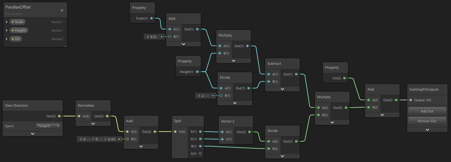
What's the point of adding the normal vector to the normal map ?
Apart from effectively dividing by 2 the normal map intensity
it's supposed to find the halfway point between mesh normal and normal map apparently, a friend told me he got better results doing it that way
I don't know what is the logic behind this, but it seems unnecessary to me.
You could also simplify a part of your graph and remove a whole lot of node :
Instead of branching after the normal sampling/intensity with the "use parallax" setting, just branch at the UV level 🙂
Furthermore, if you use the parallax UVs for the normal map, you should also use them for all the other surface map sampling (albedo, metallic, smoothness ....)
oooh thanks
If that can inspire you, I made an (unfinished) conversion of the HDRP/Lit shader in shadergraph here : https://github.com/RemyUnity/SG-HDRP-Lit

GitHub
Shadergraph version of the HDRP/Lit shader. Contribute to RemyUnity/SG-HDRP-Lit development by creating an account on GitHub.
thanks, i'll take a look!
anyone else find it really annoying that the property settings are now in another window...
I feel like UX just got worse in SRP 10
I haven't used v10 much yet, but I agree
and those gridlines are like not useful at all?
it's like just 'roughly indicating', but does not feel exact at all, and the nodes don't snap or anything
For example, here it shows the vertical line, but the same line is shown for multiple positions... which one is it?
there's only 1 x-position for the node where they are perfectly aligned right?
Yeah I've noticed it doesn't snap, was a bit confused at that. I assume it's bugged or still in development maybe
I hope so!
I do like that you can now easily target both HDRP and URP, probably they spent a lot of time on that 'restructure'
Unless there's an extra key to hold down? The roadmap seems to suggest that node alignment / snapping is "released (beta)"
double click on a connection to add a 'reroute' node is really nice also
hmm, I tried shift, but then the gridlines don't show at all
also, for some reason, I dislike that tree view search for adding nodes, I usually takes me longer now to get the right node, but maybe I just need to get used to it
I think before I could just type a and enter, and get an add node
why would I want to select a 'category of nodes'? If I press a, just auto-select the first node with an a
this is very annoying, but I'll stop whining haha, after all I'm using a beta version so let's hope some of this improves
Covid be like:
hello everyone, I swear to god if someone manages to help me with this I will offer them a beer or, being Italian, a pizza.
I have a problem that I have not been able to fix for quite a few days now.
I have a character, pretty high resolution, so it's got a skinnedMeshRenderer with a few submeshes, to have high res textures for all the different parts like face, torso etc.
I have a very very very simple unlit shader that takes two textures as input, and blends them in the pixel shader.
Basically, for reasons that I won't go into, one of the two input textures is a RenderTexture.
Well, if I do actually feed 1 Texture2D and 1 RenderTexture, only the shader for the SECOND submesh (index 1, the face) actually works. All the other shaders update in their little material preview in the editor, but won't actually show the blended texture on the character, only showing the Texture2D. If I copy the RenderTexture to a Texture2D before feeding it to the Shader, it works fine for all submeshes. Now, you might think "well just do that then, no?"... well no, because I have some very strict performance requirements and the overhead from the texture copying is too much.
I know for sure the RenderTextures are all working correctly, because I also attach them to a plane to see them for debugging purposes and they're all fine.
What the hell is going on? I tried everything and I can't figure out what's wrong, really. Any ideas?
Hi everyone, i have this problem with that grass texture where it shows an edge which it didnt before. i already set the wrap mode to clamp (it wasnt before and was working fine), refreshed the details, reimported the texture from an older backup. nothing works. it started showing up after adding a few more grass details
@paper anchor And as a sanity check, if you feed a second Texture2D instead of the RenderTexture, does it work as expected?
I guess that's what you're saying by copying it to a Texture2D
hello. I'm relatively new to shaders. How would I make one color on the object glow in the dark?
well it doesn't have to glow. just be bright
The short answer is to just return a bright color when you want a bright color
But if you're using something like Shader Graph or surface shaders, you'll want to pipe that bright color into the Emission output
I don't do visual shaders tho
free version
but I think I understand it now. I tried it before but I did it wrong. ty
I guess that's what you're saying by copying it to a Texture2D
@low lichen yeah, if I feed a Texture2D it works
Just wondering, in shader graph is there an easy way to access an object's rotation like you can with it's position using the Object node? I'm thinking about creating a shader with world aligned textures, but with the texture rotation still aligned to the object's UV
making a shader for text in the shader graph was so unintuitive
where should i post things so people could find them in the future? i couldnt find anything online
@primal eagle Reddit / GitHub / Unity forums / if you can explain how you did it: YouTube
stuff like this makes me wonder if Unity could enforce subgraph testing for new features: https://github.com/Unity-Technologies/Graphics/pull/2325
GitHub
Purpose of this PR
Fixed https://fogbugz.unity3d.com/f/cases/1221317/
Testing status
I tested the POM node in a subgraph, as well as in a normal ShaderGraph. I verified that we can still put two P...
I mean I've known that to not work on subgraphs ever since the feat got there and it's nothing new for me that subgraphs break individual feature nodes
but ultimately you'd expect subgraphs to work as well as main graph
the downside of current situation is that it's highly risky to start building your things straight with subgraphs as you often end up looking for the fail on your own nodes when it's often actually the subgraph code from Unity that is broken
also pretty sure custom function node is still treated differently in subgraphs (talking about things you could pass there outside the functions if it's in main graph)
question on getting scene depth in URP, I know I can NOT use the depth node within the Vertex section. Is it possible to use a custom node to get depth for use in vertex part? if so how?
I would have thought using SAMPLE_TEXTURE2D_LOD but then how do I convert it to usable information?
@thick fulcrum You would normally use the Linear01Depth function
So you could either use a custom function node to just write the code to sample the depth texture, or try to do the math with nodes
The function is quite simple:
float Linear01Depth(float depth, float4 zBufferParam)
{
    return 1.0 / (zBufferParam.x * depth + zBufferParam.y);
}
The zBufferParam can be found as a global variable called _ZBufferParams
@low lichen brilliant! that works
I had looked at that function but ZBufferParam was eluding me, add in the global variable and jobs a good one.
Thank you!!
So with the built in renderer we can use the callback
OnRenderImage(RenderTexture src, RenderTexture dst)
but that is not available in URP
So I tried to create a ScriptableRenderPass and handle the code for the shader there
I just realized that there's a bit too much code to paste here so I guess I'll open a forum post instead
Anyway, guys anyone using KinoBloom?
https://github.com/keijiro/KinoBloom
I have issue about Thereshold
Editor bloom effect not same in android..
I'm setting gamma but in android devices i'm seeing it more lightly....
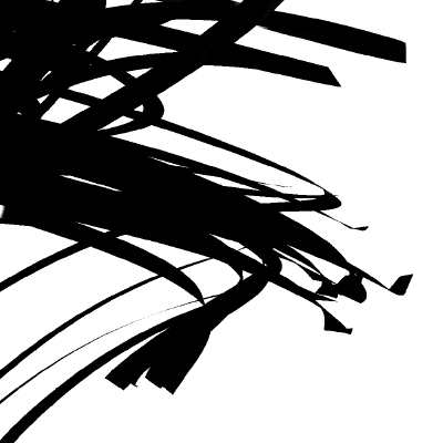
GitHub
Bloom effect for Unity. Contribute to keijiro/KinoBloom development by creating an account on GitHub.
@thick cradle Maybe you're using HDR in the editor but not on Android?
Anyone experienced with Shaders, would you be able to help me for 5-10mins? 🙂
I can help here, but no vocal
I have a detail map i'm trying to apply to the main texture, but it seemingly wants to render below the main texture, not on top, any ideas how to fix this? 0-0
hey everyone, I have installed shadergraph, but under my "Create > Shader", there is no "PBR graph". Am I missing some prerequisite? I've also set up my render pipeline to be URP... I think they are compatible?
it is showing Blank/Sub/VFX graph however
@ripe pagoda head to the package manager and make sure you have the shader graph packages downloaded
also, make sure everything in Package Manager is fully updated
Usually you just have to install URP, as shadergraph is already included. If you are on newer versions, the master nodes have been replaced with the "master stack", so the individual unlit/pbr might not be there anymore
it is currently installed (9.0.0-preview.55)
oh ok, probably as Cyan suggested then
so is this what I'm supposed to see then?
Lit Shader Graph
Yea, the Lit Shader Graph probably replaced PBR. Probably same thing
cool, thanks, did not know that!
I imagine they merged the two as you can set up a Lit shader to be a PBR anyways
Or you can create a Blank Shader Graph and set up the graph settings manually in the graph inspector
Yeah, it's all merged so that graphs are shared between URP & HDRP I think
@grand jolt What kind of detail mat are you trying to blend ?
Albedo / normal / .... ?
Maybe look at the "blend" node, where you can set the blending mode
albedo, the normal works fine, you can see the extra normal of the frog in the screenshot, it was just the albedo, I know it's there it just seems to be underneath the MainTex texture i think, you can see hints of it here:
i'm feeding the output of the parallax into it as you suggested yesterday
unless there are some maps the parallax shouldn't effect..
aha!, almost got it, a blend node on overlay mode produces this:
not sure why it's ignoring the alpha....
also I noticed, you have to treat the blend in the order you want the maps to appear in, so detail on top, blending into MainTex below
which is a vital thing I've never seen in documentation AFAIK 0-0
You'd usually set the Opacity value on the Blend node to an alpha channel of one of the texs I think
the issue I have there is, I have seperate opacity for both detail and main texture
I hardly ever use the blend node tbh, I just use Lerp (which is what the "Overwrite" mode is anyway)
you think lerp may solve it? i'll give it a shot
The blend node uses lerp in the background anyway, it just depends on how you want them to be combined
nah lerp didn't work
does anyone around here have a working case feeding a NativeArray<Matrix4x4> into ComputeBuffer and using it successfully with DrawMeshInstancedIndirect?
with URP
@heavy ether Do you have a custom shader that's trying to access that compute buffer?
yeah, im just not 100% sure if im doing it correctly
            v2f vert_simple2(appdata v, uint instanceID : SV_InstanceID)
            {
                v2f o;

                UNITY_SETUP_INSTANCE_ID(v);

                o.pos = TransformWorldToHClip(mul(_Properties[instanceID], v.vertex));

                return o;
}```ive tried using StructuredBuffer<float4x4>
and i tried using it in combination with TransformWorldToHClip, TransformObjectToHClip and without either of those just using the matrix to vertex multiplication, but i cant get the objects to appear
@heavy ether So, it could be that the buffer has invalid data. To test that, you could replace the buffer with a single global variable
with Shader.SetGlobalBuffer();?
No, Shader.SetGlobalMatrix
Doesn't have to be global, just replace the buffer with a single matrix
If that works, it's something to do with the buffer or the instance id.
well matrixes are calculated correctly, because i have them working ok with DrawMeshInstanced
im now trying to rework that to DrawMeshInstancedIndirect to get around the 1023 count limit
so im basically doing everything the same as for DrawMeshInstanced, just instead of feeding the matrixes directly, i created ComputeBuffer, used SetData on it and then used SetBuffer on MaterialPropertyBlock
And what's your argument buffer look like?
            args[1] = (uint)objectCount;
            args[2] = (uint)mesh.GetIndexStart(0);
            args[3] = (uint)mesh.GetBaseVertex(0);
            cbArgs = new ComputeBuffer(1, args.Length * sizeof(uint), ComputeBufferType.IndirectArguments);
cbArgs.SetData(args); ```i used this for args buffer, found it online
and actual buffer with matrixes like so: cb = new ComputeBuffer(objectCount, sizeof(float) * 16);
i did it guys. i made a yellow circle with ~math~
i realize none of you knew i was on this journey but still
nope, didnt work with a single matrix either
i might not be doing the shader part right, im not that good with them, mostly just try&error approach
ok, that was a solid clue, turns out the place i was fucking around in the shader was definitely wrong, so for now ive got some other stuff to try, thanks
well you see uh.... i dunno
What's the math behind it?
fixed3 color = (sin((i.position.x + 0.3) * 5)) * (cos(i.position.y * 5)) * 0.5
then step(0.356, color) for the red and green
How about a simple distance check from the center and compare it with the radius?
const float radius = 0.5;
float dist = distance(float2(0.5, 0.5), i.position.xy);
fixed3 color = dist < radius ? fixed3(1, 1, 0) : 0;
I could try that
i'll have to look up some of that code though, i'm still a beginner. Not sure what the ? and : mean there
It's a ternary operator. You can find the same syntax in C#. It's just to simplify an if-else:
const float radius = 0.5;
float dist = distance(float2(0.5, 0.5), i.position.xy);
fixed3 color;
if (dist < radius)
{
    color = fixed3(1, 1, 0);
}
else
{
    color = 0;
}
(if expression) ? (do this) : (else this)
It's not as simple until you understand it. Then it's a lot simpler.
I am trying to use GL commands inside the Execute function in a ScriptableRenderPass to set the TEXCOORD1 in the vertex shader but it doesnt seem to do anything. Anyone know if it's even possible to use GL. in URP ?
            GL.PushMatrix();
            GL.LoadOrtho();

            blitMaterial.SetPass(0);

            GL.Begin(GL.QUADS);

            GL.MultiTexCoord2(0, 0.0f, 0.0f);
            GL.MultiTexCoord(1, bottomLeft);
            GL.Vertex3(0.0f, 0.0f, 0.0f);

            GL.MultiTexCoord2(0, 1.0f, 0.0f);
            GL.MultiTexCoord(1, bottomRight);
            GL.Vertex3(1.0f, 0.0f, 0.0f);

            GL.MultiTexCoord2(0, 1.0f, 1.0f);
            GL.MultiTexCoord(1, topRight);
            GL.Vertex3(1.0f, 1.0f, 0.0f);

            GL.MultiTexCoord2(0, 0.0f, 1.0f);
            GL.MultiTexCoord(1, topLeft);
            GL.Vertex3(0.0f, 1.0f, 0.0f);

            GL.End();
            GL.PopMatrix();
@raw dock Not sure. I'd probably look into using the FullScreenQuad passes here : https://github.com/Unity-Technologies/UniversalRenderingExamples/tree/release/2019.3/Assets/Scripts/Runtime/RenderPasses
Aka,
public override void Execute(ScriptableRenderContext context, ref RenderingData renderingData)
        {
            Camera camera = renderingData.cameraData.camera;

            var cmd = CommandBufferPool.Get(m_ProfilerTag);
            cmd.SetViewProjectionMatrices(Matrix4x4.identity, Matrix4x4.identity);
            cmd.DrawMesh(RenderingUtils.fullscreenMesh, Matrix4x4.identity, m_Settings.material);
            cmd.SetViewProjectionMatrices(camera.worldToCameraMatrix, camera.projectionMatrix);
            context.ExecuteCommandBuffer(cmd);
            CommandBufferPool.Release(cmd);
        }
But instead of RenderingUtils.fullscreenMesh you'd need to pass in a different one. Probably not going to want to create a new mesh every execute, but maybe create it in the constructor and set the uvs in execute?
A SRP RenderPass just queues commands, it doesn't execute them immediately
So GL commands wouldn't work in them
@regal stag oh nice, thank you! I will look in to that 🙂
@low lichen Oh I see, thank you for telling me!
still having trouble with this mask map, each time i activate it my texture loses some detail:
Mask map off:
on:
merging the B output of the mask with the main texture:
Hello, I'm looking to solve a visual issue I'm having with a project. I have 2D characters that are rigged and skinned with Unity 2D tools and I am trying to get that whole character built from Sprite Skin components to act as a mask for other sprites.... the issue I have is the Sprite Mask component does not work with Sprite Skins.... does anyone have experience with this?
Hi everyone, I have a RenderTexture set to Tex2DArray, and I pass it to a compute shader and write to different slices of it. This is fine, but when I build for android, the z index seems to not work properly... like if I feed "1" as z, it mostly writes to 0-slice, some pixels on 1-slice... it does not seem to show a particular pattern, it just does not work as expected
@grand jolt In HDRP/Lit, on albedo, the detail map R, is blender in overlay mode with the main albedo, using the mask map B
@thick cradle Maybe you're using HDR in the editor but not on Android?
@low lichen Didnt understand if you talking about on graphic settings yes its closed
Hey i wanna start to make more shader and vfx but i need some Help to learn it because it is very different as normal programming -
I wanna start with a 3d pixelated Fireball, have somebody good tutorials or something?
@native spoke look for vfx graph fire tutoreals on youtube and go from there i would say
Anyone used this bloom?
https://github.com/mightypanda/Unity-Fast-Bloom

GitHub
Probably the fastest bloom implementation. Contribute to mightypanda/Unity-Fast-Bloom development by creating an account on GitHub.
Looks great on editor but im just seeing black screen on mobile
Is there a way to computationally run multiple passes until a condition is met? I'm looking to run a frag multiple times on the image. The amount of times will depend on some variables
I would like to do everything in the shader if possible
how can we do cross section in PBR shader graph ?
Is it possible to have a shader/material variable hold different variables for different gameobjects?
I thought you needed to use ECS and the hybrid renderer to hold different variables, but maybe that's just for shadergraph?
found it...material property blocks. But that seems to be text shader only, not shadergraph
@paper anchor I had the same issue and couldn't solve it. Switched to blitting to the texture array instead.
Which had better performance too
@mossy night Material Property Blocks will work for any shader
But if you want it drawn with instancing, then you need to add special support for it in the shader, which Shader Graph can't do
Trying to achieve this plane blur, found something from 2013-14 not much recent any ideas gang?
standard render or URP/HDRP?
Standard
I mean, world space UI would work right ?
Blurring some background objects
Probably underthinking it
is this for mobile or desktops?
by it's nature blurs are not really performant 😄
anything you found even from 2014 should still be relevant
Hm ok, I'll give it a shot I've had some errors with old stuff before is why I ask
Maybe better ways have come about since then etc
basically it's a full screen grab and pixel offset, repeated to make it blurry... more times it repeats the more it's costing
Yea or like render texture right
you could perhaps do something like a refraction blur with a texture
I saw a frosted glass example I'll see if I can do something from there, cheers 👍
I want to rotate a texture by camera in shader how can I do that ?
@thorn ore you might need to explain a bit more or give example, I don't quite understand what you want to achieve
@thick fulcrum I have a Shader generates sky , I want to set the xy of cam pos in my shader with unity camera
currently I'm doing :
    float3 forward = mul((float3x3)unity_CameraToWorld, float3(0, 0, 1));

                rd.xz = mul(rd.xz, mm2(forward.x));
                rd.yz = mul(rd.yz, mm2(forward.y));
but it doesn't work properly it works fine only in X or Y rotation but gets wrong when doing XY together
🤔 you want to rotate the object or camera? there are global variables to get the cam view position which maybe simpler to use in the maths
this is the shader :
https://gist.github.com/ya7gisa0/47475c0734a2db0d1320d2582564f77f
I removed line 164 now I want to set this view with unity camera
It should be simple but I can't figure it out in unity
it's probably simple, but I'm missing it... so I'm lazy quick net search yields this which might help but not sure you have access to what you need in that stage https://forum.unity.com/threads/camera-rotation-in-shader-solved.591220/
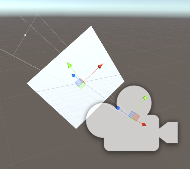
Unity Forum
I'm using the shader like the one at the end of this post to detect objects using a camera and a 1x1 RenderTexture. It gives me the UV coordinates and...
I read this page before unfortunately didn't solved my issue yet
I've generated a shader graph shader, and I tried making it write to the depth buffer but I get artefacts
// Render State
Blend SrcAlpha OneMinusSrcAlpha, One OneMinusSrcAlpha
Cull Back
ZTest LEqual
ZWrite On
How can I fix Moire patterns in procedural textures using Shader Graph?
Does anyone here have experience using the sphere mask node?
I'm trying to achieve foreground wall occlusion that visually looks like a cross section. Something between Sokpop's wamu wamu 2: https://sokpop.itch.io/wamu-wamu-2 and this sphere mask demo video: https://youtu.be/QrMfE3xn-lM
I think wamu wamu 2 is just using an ellipse and a one-minus operation as a mask for a circle sprite on top of the 3D environment.
This gives the illusion of a cross section by keeping the environment's Y rotation static. However, I plan to use a sphere mask to visually improve wall occlusion when the player is inside their home (where they can rotate the view).
I feel like it shouldn't be too complex but I'm confused with the custom renderer feature's overrides. I feel like I could use stencil or camera overrides but I'm not entirely sure what each does and am having trouble finding documentation. The one documentation page that continues to appear in my google searches is the Scriptable Render Pipeline asset page.
I've attached a screenshot of the Render Objects renderer feature with all the override boxes ✅ just to display all the options - these aren't my current settings.


Shader that clips out pixels using a spherical mask. Edge emission and noise are added for effect. Created in Unity using CG. Buddha Preaching 3D scan is provided by The British Museum Sketchfab page.
I had been looking at a thread from Mike Blackney about my question on how Dead Static Drive (made in Unreal) achieves it's wall occlusion. Just as possible reference
https://threadreaderapp.com/thread/1318000382467993600.html
Thread by @kurtruslfanclub: There's a few things we need to do to get wall fades working well Some of it is purely in-shader and some requires code as well [thread] we have a really simple shader...
If anyone has any ideas or experience using the sphere mask node please let me know! thanks! 
Is there a way to get the world position from a raycast hit originating from the camera in shader graph?
probably with scene depth, linear eye depth I believe is in world units
what are you after doing though?
using the coordinates from that raycast hit as the Center input for a sphere mask node
would the Projection node be useful?
https://docs.unity3d.com/Packages/com.unity.shadergraph@6.9/manual/Projection-Node.html
hmmm
probably easier just to feed the vector 3 from c# code
Ideally you'd do the raycast in C# and send it into the shader, using material.SetVector / Shader.SetGlobalVector
Okay nice, another member on my team already has a simple wall occlusion c# function using a sphere collider to occlude all objects it touches. I'll try combining the two
Idk if it has something to do with shaders, but I'm new to the terrain system in Unity and I am confused... Idk why, but my grass seems to have some pixels floating above the actual grass, but thats only on the terrain. If I use a mesh and attach a material with this texture it seems normals... Does somebody now a fix? ^^
I had been using an unlit graph for this - would it make more sense to try out the newer VFX Graph? I haven't used it at all yet
I haven't used it, but the VFX Shader Graph is only used with the Visual Effect Graph, which is for creating particle effects. It's not for regular shader effects applied to materials. So going from an unlit graph to a vfx one wouldn't make sense.
Ah so it’s for creating particle effects
@grand jolt Hey Beatrate,
I'm totally guessing here, but if you procedurally output to that texture and THEN to the screen, MIP mapping and anisotropic filtering may help you. Play with the settings.
Ye, guess so. I switched to a boring triplanar projection of a premade texture since it's just a prototype.
I checked out the Unity forums and it appears even the mighty 0lento had only a partial solution for this when someone asked about it.
@grand jolt I'm curious though, what was my solution?
Something with fwidth/ddx/ddy?
what was the issue again? 😄
Still had distant Moire patterns so that's why I said partial.
moire issue sounds more like lack of mipmaps
Moire patterns on procedural textures.
I think Unity should generate mipmaps automatically if you modify and apply Texture2D etc
No no, I mean albedo calculated algorithmically in the shader.
ahh