#archived-shaders
1 messages · Page 173 of 1
So you'd want something that's more of a percentage type of thing.
Plus or minus. So like -1.1 or 1.1 if I read it correctly.
Or maybe .001 or -0.001
But that wouldn't make sense with a vertex color as input...
Well that might.
Anyway as a test I commented out "v.vertex.z = desiredpos.z * o.vertex.w / desiredpos.w;" and the road reappeared so it is at least working in some fashion.
However Z offset of -1.1, 1.1, and 0 do not make the road reappear.
Well zero would eliminate the offset completely
You want to, as I understood you, offset a min amount to be toward the camera. He's doing a vector toward the camera pos (or from the camera pos). And then scaling it and adding that to the vertex pos.
Yes, and if I eliminate the offset completely, that should have the same effect as commenting out that last line to set the vertex Z value.
But it doesn't. The road dissapears. Which tells me the z value is being lost or corrupted somehow in all the math.
Unless by offset you mean the Z is being set to 0 rather than the offset from the Z is being set to 0.
UnityObjectToClipPos(v.vertex + zoffset * float4(cameravec.xyz, 0.0));
But that ought to just return the vertex position plus nothing if I set zoffset to 0.
Though I could be wrong, since I don't understand this part: "float4(cameravec.xyz, 0.0)"
What is the 0.0 on the end? And why is the one above dealing with world space 1.0? Is that some kinda vector length? That might explain the offset not working if so, but not the road disappearing when the offset is 0.
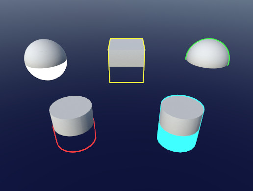
Hi. I’d like to achieve something like this:

Here’s a graphics breakdown of the environments in Thousand Threads.
#screenshotsaturday #indiegame #gamedev https://t.co/iwi65ixvZj
Retweets
130
Likes
631
But instead of each object just being one shade, I’d still like the object to be lit, but I want its gradient map to be controlled by a custom colour palette. Is this possible through a similar method?
ie. no texturing. Each material is just one flat colour that shifts to another colour depending on how much it's lit. And I want to be able to set the colours in a colour palette.
That's the w component of the vertex. He's got xyz, and is setting w to 0 of the 4 component vector.
That's a bit tricky to explain, it it's setting the perspective divide. To convert from clip space to NDC, it divides by .w component. And that happens in hardware. Basically the farther away it is, the more it is divided.
Or something like that.
Such that the view frustum gets a perspective and the farther away it is, the more "space" it covers.
It moves everthing further away more toward the center, compared to straight lines.
Vanishing point type of thing
Happens in hardware.
@sinful shuttle Also try .1 and -.1 or maybe .01 and -.01 for offset.
None of those works. The road mesh is simply gone.
I'd have to play with it I guess, But I can't now, IRL stuff in the way. I'm back and forth from the keyboard right now as it is.
Anyway, you want to add an offset that's toward the camera, to the vertex. But I'd have to play with it. I'm not even sure how much perspective correction is needed if it's a small offset.
Right now it looks like he's just modifying the z value of the vert multiplying by the ratio of what the desired pos.z is and the old-pos.z or something.
can I make my own sampler2D manually? where would I learn about what is in there?
@ripe pagoda sampler2D just represents a 2D texture object that can be sampled. Are you asking if you can create a 2D texture yourself?
ah, I was specifically interested in changing the UV I think. Was trying to understand whether I could use TRANSFORM_TEX with my own UV to get it to compute some scaling/offset for me.
TRANSFORM_TEX is just short for uv * tiling + offset
But uses the tiling and offset values from a texture, which unity stores in a float4 textureName_ST (.xy being tiling, .zw being offset)
ah ok, if it's that simple, then I probably don't need it, thanks! 🙂
How can I get my particles to emit from the emitter but still move in world space?
Can compute shaders be used for... shading?
It's just I'm considering a possibility of approximating some complex shading functions via neural nets
Since they are basically lookup tables, that almost don't take up memory and scale up very neatly
@dreamy kernel Compute shaders can be used for anything, so absolutely
Great
By the way, how could I have a pixel color of a background entity to be an input to my shader?
@dreamy kernel Not simple. You would need a texture of the background. The trouble is, you can't draw to the same texture you're reading from (on most platforms)
I heard just now that I should use GrabPass, is that right?
That's one way to do it. I think what that does it it copies the screen texture before rendering your object
But it's not very efficient at it, so it's probably the slowest way to do it
But the easiest
What's difficult about adding GrabPass { } to your shader?
It doesn't
But URP has it's own solution for that
I'm sure you can find it if you search "unity grabpass urp"
URP has the Opaque Texture option to replace the grabpass. It basically outputs the camera texture after rendering opaque objects, so in a transparent shader you can get the texture. I believe it's more performant this way, but the down-side is that it only contains opaque stuff.
Wow so glad I caught this.
Wasn't sure why my transparents weren't looking right when overlapping.
transparents require blending, and usually sorting (unity does that part for you).
I'm having issues with some shaders in VR where the applied 2D texture acts as a billboard and follows the heads Z rotation (when you lean your head side to side). Now, I don't know much at all when it comes to shaders, but could someone point me in the right direction as to what piece of code determines it. I was thinking "viewDir", but not sure what to use instead there if that's the case.
Hey, could someone help me out? I'm trying to figure out how to do Pixel perfect UV displacement. These pixels should not distort
round your UV value to the size of a pixel
Ok. That works if I'm using a displacement map, right? [Kinda like the ones in Mario Galaxy]
i found some code for a shader i want to use, but I dont know how to import it into unity
@crimson trail what does the code look like?
like normal code
https://github.com/Shrimpey/Outlined-Diffuse-Shader-Fixed/blob/master/CustomOutline.shader

GitHub
This is a fixed version of diffused outline shader from http://wiki.unity3d.com/index.php/Outlined_Diffuse_3 - Shrimpey/Outlined-Diffuse-Shader-Fixed
there's the link
why not just copy the shader code into a .shader file?
ok i had to tell my computer to open the file with visual studio
now idk how to add it to a matriel , as i'm using URP
@crimson trail create a material, then select the Outlined/Custom shader from the shader dropdown
hey, how can I make a height map, and a roughness map in the unity shader graph?
@calm hollow your question is a bit vague, can you clarify what you're trying to do exactly?
you should just be able to plug in anything black and white into roughness/height
well, I am in a urp render pipeline @hearty wasp
and the regular lit shader doesnt have that
ah I've mostly worked with shadergraph in HDRP, let me check what the possibilities are in URP real quick
ok
@calm hollow which of these are you using?
the pbr one
smoothness = roughness, just the same except it's inversed
and for height, well you could use vertex displacement
a black and white image yeah, and your 3D model needs to have enough tris to be able to displace
ok
there's other ways of displacement like a pixel parallax effect but urp doesn't have that out of the box I believe
so it's more complicated to make
alright then
@sinful shuttle I got some time to play with it.
IDK if this is what you wanted or not, so full disclaimer.
However this will nudge the verts toward the camera position as you requested. I think it can mess up shadows though, so watch for that. Anyway, try this in your Vert() function:
v.vertex += float4(normalize(ObjSpaceViewDir(v.vertex)) * _VertOffset, 0);
No warranties expressed or implied, use at own risk! ;)
That ObjSapceViewDir function is a helper function that gives you a vector to the camera relative to object space. So all it does is normalize it and scale it.
Worth a try to see what it does, I can't recreate your scene so...
Make sure you have the "addshadow" keyword in your #pragma Surface line.
@hearty wasp is there any other way of having a heightmap. I don't think i want to use vertex displacement because I want to keep my walls low poly.
there's tessellation which basically adds more polys as your camera comes closer to the shader, and there's pixel parallax which is basically not really height but more of an illusion
but I couldn't tell you how to make those from scratch
HDRP has both of those out of the box though, in its standard hdrp lit material
ok
idk what your project is or how far you're into it but if you really need high quality materials/visuals you may wanna try out hdrp
ok
I can recommend just making a new hdrp project on the side and just doing a few art tests with the materials for whatever you're doing @calm hollow
yeah my project isnt gonna be looking that good. I just wanted to use a height map. My textures already look good with a normal map, but I just want a bit more detail, to make my models look really good.
then you'll probably have to settle on what you have or go all in on making some sort of heightmap shader yourself, but that can be tricky
I've been following @regal stag Non-Ecluiodean Shader Thread https://twitter.com/Cyanilux/status/1193513267534151680?s=20, first it's amazing 💖, second if anyone can help me, I'm currently not understanding how to replace all pixels and not only the ones without anything besides

Hey! I made some impossible geometry! Not only is the interior different for each face... but there's also 5 of them!?
Stencil shaders are cool. ✨👀
(see thread for a mini-breakdown)
#unity3D #madewithunity #shaders https://t.co/b0hKsDF5iI
Retweets
127
Likes
794
This is the Shader
Shader "Custom/Stencil"
{
    Properties {
    [IntRange] _Stencil ("Stencil Ref", Range(0, 255)) = 0
    }
    SubShader {
        Tags { "RenderType"="Transparent" "Queue"="Geometry-10" }
        Pass {
            Stencil {
                Ref [_Stencil]
                Comp Always
                Pass Replace
            }
            ColorMask 0
            ZWrite Off
        }
    }
}
Update: The problem is on the Forward renderer config, i'm trying to get the right configuration, Sincerely i don't know much about stencils and ZTests, but i'll try to get it right
Hey guys. First, i am sorry if this isn't the place, but i am searching little help (i will pay the price of course) I am trying to implement some basic mechanic from tutorial i've seen. The thing is i've written the code, but the code is linked with some VFX shader graph and shaders that i cannot recreate (they are pretty simple, i just don't have the knowledge to make them, i've tried...) So if anyone is skilled in that i would like to get some paid help. Thanks ! (If my post violates the rules, i will delete it)
@fathom wharf could you describe in more detail what you need?
Yes, let me PM u
@cosmic prairie Looks like it's nearly perfect. But a bit rough. I hope I did this right
@deft frost looks great!
i need help altering this Kino streak shader.. it adds a horizontal flare to where the mesh shines.. i want to just rotate it slightly so it's diagonal or add two streaks.. tried some things with switching the X's to Y's in the code: https://github.com/keijiro/KinoStreak/blob/master/Assets/Kino/Streak/Shader/Streak.shader
but there might be a way to do it with the widths in the csharp controller: https://github.com/keijiro/KinoStreak/blob/master/Assets/Kino/Streak/Streak.cs
if anyone has input or could point me in the right direction.. would be deeply appreciated

GitHub
Anamorphic lens flare effect for Unity. Contribute to keijiro/KinoStreak development by creating an account on GitHub.
GitHub
Anamorphic lens flare effect for Unity. Contribute to keijiro/KinoStreak development by creating an account on GitHub.
I have a bit of an issue of my own, it's my first time picking up water shaders again
and I just can't get the hang of edgefoam

what I attempted doesn't really work at all haha
here's the edgefoam part of the graph more clearly: https://cdn.discordapp.com/attachments/440531990274506752/759580040559722496/unknown.png

@hearty wasp The Screen Position node needs to be set to Raw mode in order to be able to access the w/alpha component properly
ah honestly? could that be all I did wrong?
I'll try it out, one sec
@regal stag well that pretty much worked, thank you! Now I just gotta find the way to blend it
idk what kind of shader thing I made
how would i get fresnel to be around the edges of any shape, it works for a sphere but for a cube it's weird?
or is that like illegal or something
@safe gate Yes, the fresnel police will be knocking on your door soon
oh no
does anyone know like how those screenspace shaders are made? i don't understand the script at all.. with the uvs and stuff if anyone has links/resources to how to learn that please lmk
@grand jolt What's a "screenspace shader"?
@safe gate Did you figure it out?
I had the same question a while back but I dropped it, so I'm curious 😄
Fresnel doesn't allow you to do object outlines. It just happens to look like an outline for spheres.
I can't understand why outlines are still a mystery in 2020
The unity editor uses them.
It's more involved than what a single shader can do
I have so many shader questions, it's insane. Is there some sort of master course I can follow?
Unity renders outlined objects to a separate texture and blurs that texture before adding it back to the scene.
That doesn't sound great for performance 🤔
Certainly not for mobile
nah i went to bed
Fresnel doesn't allow you to do object outlines. It just happens to look like an outline for spheres.
oh
oh its just a flushed emoji
I doubt there's any real well performing way of making object outlines other than either using some kind of image effect, or the Toon Outline shader pass
What's a toon outline shader pass?
Toon
Yes, I made a typo 😄
O
Actually... Never mind. My real question is: where do I find a good course?
Use the Quick Outline tool for your next project. Find this and more particle & effect tools on the Unity Asset Store.
I don't mind paying
This does outlines by drawing the object again, but a little bigger
haha that's how I solved it the first time, but it looked weird in complex shapes
@deft frost doesn't look right to me yet
My end goal is having an effect to dissolve objects as they hit the floor. Like the floor is a portal to nothingness, basically. To get there though, I need to know the path and I have no idea
did you do the following? add displacement to the UV, multiply the UV with the size of the texture in pixels, round it, then divide it with the size of the texture in pixels?
@deft frost
i need help altering this Kino streak shader.. it adds a horizontal flare to where the mesh shines.. i want to just rotate it slightly so it's diagonal or add two streaks.. tried some things with switching the X's to Y's in the code: https://github.com/keijiro/KinoStreak/blob/master/Assets/Kino/Streak/Shader/Streak.shader
but there might be a way to do it with the widths in the csharp controller: https://github.com/keijiro/KinoStreak/blob/master/Assets/Kino/Streak/Streak.cs
if anyone has input or could point me in the right direction.. would be deeply appreciated
@grand jolt @tranquil fern stuff like this not sureif i have the right terminology
GitHub
Anamorphic lens flare effect for Unity. Contribute to keijiro/KinoStreak development by creating an account on GitHub.
GitHub
Anamorphic lens flare effect for Unity. Contribute to keijiro/KinoStreak development by creating an account on GitHub.
Can't I use coded shaders with URP at all anymore?
sure you can, just look at the unity ones or some examples around the net.
But they're all pink 😄
@tranquil fern I've used some Udasity courses when I got a good deal on them. Also used Udemy. There's also kindle books.
Much of this stuff is on the web/youtube though. But sometimes it's fun to have a structured course if it's reasonably priced.
I still need some help with a terrain shader that's supposed to stop a path mesh placed on a terrain from clipping through it in places.
Here's what I've got so far...
One person suggested the following:
   {
        v2f o;

        float zoffset = v.color.r;
        o.pos = UnityObjectToClipPos(v.vertex);
        float3 cameravec = normalize(mul(unity_WorldToObject, float4 (_WorldSpaceCameraPos, 1.0)).xyz - v.vertex.xyz);
        float4 desiredpos = UnityObjectToClipPos(v.vertex + zoffset * float4(cameravec.xyz, 0.0));
        o.pos.z = desiredpos.z * o.pos.w / desiredpos.w;

        return o;
}```But that didn't work. v2f wasn't found and o.pos wasn't found.
I then edited the code to try to get it to work, but the path simply disappeared unless I commented out the line actually adjusting the path positon. And this happened regardless of whether I set the z offet to 1, -1, 0, or anything in between:
               appdata_full o;

               float zoffset = 0.1;
               o.vertex = UnityObjectToClipPos(v.vertex);
               float3 cameravec = normalize(mul(unity_WorldToObject, float4(_WorldSpaceCameraPos, 1.0)).xyz - v.vertex.xyz);
               float4 desiredpos = UnityObjectToClipPos(v.vertex + zoffset * float4(cameravec.xyz, 0.0));
               v.vertex.z = desiredpos.z * (o.vertex.w / desiredpos.w);
               v.vertex.xyz = v.vertex.xyz + normalize(ObjSpaceViewDir(v.vertex)) * zoffset;

}```Then I tried this, which seems like it might be giving a similar result to using the Offset command that wasn't doing as good a job as I'd like because the path still had to be like 0.1 units above the terrain up close for it to work. At least, without normalizing the result. When trying to normalize it, it just broke and the path disappeared no matter the offset:
            appdata_full o;

              float zoffset = .1;

            //v.vertex.xyz = v.vertex.xyz + normalize(ObjSpaceViewDir(v.vertex)) * zoffset;
            v.vertex.xyz = v.vertex.xyz + ObjSpaceViewDir(v.vertex) * zoffset;

        }```
So now I'm wondering if perhaps pushing the vertices towards the camera a bit might not be the best approach? I'm thinking instead what if I were to move the vertices up along the Y axis, in world space, but do so more in the distance than up close? Or maybe I just screwed up all the math from the original suggestion because I could never get that to work unaltered and I'm not sure exactly what I'm doing.@sinful shuttle I believe with the first example the mistake is in first line, try v2f vert (appdata_base v) it should then compile. If it yields the results you desire, I cannot say but worth a try.
@thick fulcrum Nope. That didn't compile. Complained about lack of v2f struct which I tried to add, then lack of inout, then color parameter, then pos...
            {
                float2 uv : TEXCOORD0;
                UNITY_FOG_COORDS(1)
                float4 vertex : SV_POSITION;
            };


            v2f vert (inout appdata_base v)
            {
                v2f o;

                float zoffset = 1; //v.color.r;
                o.pos = UnityObjectToClipPos(v.vertex);
                float3 cameravec = normalize(mul(unity_WorldToObject, float4 (_WorldSpaceCameraPos, 1.0)).xyz - v.vertex.xyz);
                float4 desiredpos = UnityObjectToClipPos(v.vertex + zoffset * float4(cameravec.xyz, 0.0));
                o.pos.z = desiredpos.z * o.pos.w / desiredpos.w;

                return o;
}```void vert (inout appdata_full v) is how vertex shaders for surface shaders are defined
Are you making a surface shader?
Yes.
Still get an error on o.pos, which I assume is because it's not in the v2f struct but then again I don't know that that struct isn't adding onto some hidden struct which seems to be a thing in shaders from what I've read the last few days. In any case, I don't know what type pos is supposed to be.
You don't define the v2f in a surface shader
Well without that struct I get "unexpected identifier o":
            {
                v2f o;

                float zoffset = 1; //v.color.r;
                o.pos = UnityObjectToClipPos(v.vertex);
                float3 cameravec = normalize(mul(unity_WorldToObject, float4 (_WorldSpaceCameraPos, 1.0)).xyz - v.vertex.xyz);
                float4 desiredpos = UnityObjectToClipPos(v.vertex + zoffset * float4(cameravec.xyz, 0.0));
                o.pos.z = desiredpos.z * o.pos.w / desiredpos.w;

                return o;
}```have you looked at some simple vertex examples in the unity manual? e.g. https://docs.unity3d.com/Manual/SL-VertexProgramInputs.html

I understand you don't have much experience in shaders, but do you also have little experience in programming in general?
Because you've defined a void function, but you're trying to return something in it
I have like 20 tabs open with various surface and vertex shader stuff.
So, yes. 🙂
Surface shaders give you limited access to extend the vertex shader
@low lichen "Because you've defined a void function, but you're trying to return something in it" -- I did that because you said "void vert (inout appdata_full v) is how vertex shaders for surface shaders are defined"
So that should also tell you that the function shouldn't return anything
There's a inout parameter, which means you just modify that parameter
"So that should also tell you that the function shouldn't return anything"
Considering how many hidden variables seem to be involved in coding shaders, I can't take anything for granted. How do I know something isn't being overridden somehow?
"There's a inout parameter, which means you just modify that parameter" -- I didn't have inout before, and I didn't know what that did. I come from a C background where I'd pass pointers or references.
Have you looked at examples of surface shader vertex functions?
Anyway to answer your question about my experience level I started coding games 25 years ago, but I'm a bit rusty on the coding part.
https://docs.unity3d.com/Manual/SL-SurfaceShaderExamples.html
Shader "Example/Normal Extrusion" {
    Properties {
      _MainTex ("Texture", 2D) = "white" {}
      _Amount ("Extrusion Amount", Range(-1,1)) = 0.5
    }
    SubShader {
      Tags { "RenderType" = "Opaque" }
      CGPROGRAM
      #pragma surface surf Lambert vertex:vert
      struct Input {
          float2 uv_MainTex;
      };
      float _Amount;
      void vert (inout appdata_full v) {
          v.vertex.xyz += v.normal * _Amount;
      }
      sampler2D _MainTex;
      void surf (Input IN, inout SurfaceOutput o) {
          o.Albedo = tex2D (_MainTex, IN.uv_MainTex).rgb;
      }
      ENDCG
    }
    Fallback "Diffuse"
  }
"Have you looked at examples of surface shader vertex functions?" -- I already answered that question. Yes. I have 20 tabs open...
Regular vertex shaders and surface shader vertex functions are separate things and it looks like you've been mixing them together
I've only just learned that this evening, but I do know surface shaders can modify vertices, I just don't know what limitations they have versus vertex specific shaders.
For example this works, though not how I want it to:
              float offset = 0.05; // How much to raise the decal one meter from the camera. 0.01 = 1cm

            // Calculate distance betweeen a vertex and the camera:
                // float dist = distance(_WorldSpaceCameraPos, mul(Object2World, v.vertex));
                // OR:
                // length(ObjSpaceViewDir(v.vertex));

            v.vertex.y = v.vertex.y + offset / length(ObjSpaceViewDir(v.vertex));

            //1 meter away = 1cm rise
            //10 meters away = 0.1 cm rise

}```I also tried this earlier: v.vertex.xyz = v.vertex.xyz + ObjSpaceViewDir(v.vertex) * zoffset; // Move vertex towards camera.
The code I was trying to get work earlier was something someone else suggested, but they have since said it will only work in a vertex shader. Why that is, I don't know.
The limitation is that you can't change the vertex position after it has been converted to clip position. The generated surface shader would be doing something like this:
v2f surfVert(appdata v)
{
    v2f o;

    vert(v); // Calling your vertex function.

    o.pos = UnityObjectToClipPos(v.vertex);
    ...
}
You mean you wanted to get this working?
v2f o;

float zoffset = 1; //v.color.r;
o.pos = UnityObjectToClipPos(v.vertex);
float3 cameravec = normalize(mul(unity_WorldToObject, float4 (_WorldSpaceCameraPos, 1.0)).xyz - v.vertex.xyz);
float4 desiredpos = UnityObjectToClipPos(v.vertex + zoffset * float4(cameravec.xyz, 0.0));
o.pos.z = desiredpos.z * o.pos.w / desiredpos.w;

return o;
I don't know what that means. And in my examples above, I can see the vertices are being moved on the screen by the surface shader.
Yes.
"The limitation is that you can't change the vertex position after it has been converted to clip position."
If that is true, why do I see the vertices moving, and why does the vert() function exist?
You can change the vertex in its local space
That then gets passed to the rest of the surface shader, which then converts that to clip position
But that code above requires being able to convert to clip position and then do some more work
Okay but I'm confused about something...
If the surface shader is converting to clip positon, and if the code above requires me to convert to clip position and THEN do some work, then is the surface shader converting to clip space AFTER the code I've written for the shader runs, invisibly in the background?
Select your shader asset in Unity and click "Show generated code" in the inspector
Cause that doesn't make a lot of sense to me. But it also doesn't make sense that if the conversion were happening before my code runs... that I could not then do whatever modification that vertex shader is doing since that needs to happen after that conversion anyway.
That's the actual shader. The whole point of a surface shader vs a regular vert/frag shader is that it does most of the boilerplate work for you.
So the vertex and surface functions are just functions that the actual shader runs in between other stuff
If you wanted to, you could get the generated shader and duplicate it and modify it
But if you modify the original surface shader, you'd have to duplicate it and modify it again to get those changes.
Btw, I totally understand how this is confusing. There's definitely a lot of hidden magic around shaders, but more so with surface shaders.
"If you wanted to, you could get the generated shader and duplicate it and modify it"
I get that. And I see the code.
"But if you modify the original surface shader, you'd have to duplicate it and modify it again to get those changes."
But I I'm not sure I understand what you mean by this.
Like if you decided to add the nofog keyword into the shader to disable fog, you'd have to do that to the original surface shader, let it generate the shader again with no fog calculations, then duplicate and make the same modifications as before.
Why couldn't I just edit that into the generated shader code? Does that one keyword generate a ton of new code that would make that infeasible I guess?
One keyword might add hundreds of lines into the generated code
In theory, you could make those same modifications to the generated shader code
Cause I just noticed there's like a dozen copies of my comments and code in this giant shader it made, so something's going on there with optimization I think.
It also makes me wonder if to edit this generated shader I would have to duplicate my code in those dozens of locations to make it work.
The generated code might have some redundant stuff in it that the compiler cleans up.
Is the surf function declared multiple times in the generated shader?
I thought that one was only declared once
Some? It's 38,000 lines... 🙂
Yeah...
Yea, multiple times.
If your surf or vert functions are duplicated, you could probably get around that by writing it in a separate .cginc file and #include it in the original surface shader
The generated shader should also do that, so you can edit it in the .cginc file
Unfortunately, this is going way beyond what's worthwhile for me to make it so these terrain decals which represent paths on my terrain always render above it without seeing them floating quite obviously above the terrain. I'm just trying to make a Halloween map of a meadow for VRChat. I only have a month to do it, and I thought it would be nice to fix the River Auto Material's shaders so they work well in VR, because the floating is super obvious.
It's kind of absurd that it seems like no one has solved this problem. Or if they have, nobody's pointed me to any shaders or assets designed to solve this problem. I mean are having decals on terrain that look good in VR really something nobody in Unity land has tackled yet?
I can't think of a simple way to fix it except just ensuring that the path mesh never intersects the terrain
Which is doable
I appreciate all your help though I have a much better understanding of surface and vertex shaders now.
I guess the path mesh is generated by this R.A.M asset you're using?
"I can't think of a simple way to fix it except just ensuring that the path mesh never intersects the terrain"
Well that's the thing... the author of R.A.M. said that the path has to be offset from the terrain because the terrain changes shape in the distance. So to avoid clipping, its necessary. I could see how if I flew high above the terrain and looked down, that would be true, though being at ground level, clipping in the distance would be less obvious.
Nonetheless, his tool generated paths which float around .1 meter above the terrain in spots, and in other places, moving it down by even .05 units causes it to clip through, so I can't move it down at all... Unless I were to manually edit the terrain in all those locations which I was attempting not to have to do. Or I guess I could edit the path but I don't know if probuilder can edit these meshes and I haven't actually used the R.A.M tool yet to see about editing the splines though that would also be a bunch of work.
I guess I just looked at it and assumed it was a rendering bug, but maybe the heights were just generated poorly by the original tool or something.
Yes. RAM is for generating rivers, but it can also be used to create roads, which in this case, are actually two ruts side by side on a dirt road that is painted into the terrain in a meadow, and some paths through the woods.
You can see the clipping about 10m away there...
But elsewhere...
Is the original shader for this path a surface shader?
maybe I'm missing something as I'm not following convo 100% but, why do you need a mesh path at all. Why not just paint onto terrain?
You lose being able to control the direction of the texture
You couldn't have tire marks with a painted texture on the terrain
that's a fair comment, but I would just use "normal decal" to create illusion for example... but are screen space decals doable in VR?
The terrain already sort of has paths painted on it but the path material does stuff like make the edges darker...
Now is this the best way to do it? I don't know. But I don't really have time to fix it either since this is supposed to be a quick fun halloween thing for VRChat.
The rocks being bright white is some kinda issue with the lightmapping, maybe being too low res cause I had to lower it to like 2 texels per meter to render it in a reasonable amount of time. Still took a half hour with Bakery.
I'm probably gonna have to run magic light probes on this cause the light probes for this whole meadow aren't placed great. My leaf piles are bright when near the ground in many places:
And I tracked that issue down to them picking light probes that are far away instead of the ones up close because they're just outside of the tetrahedron of the ones up close.
But the bright white rocks are probably unrelated to that.
I think you might be too critical of it (we all do it), the people playing will probably not notice half the issues you do. I'm sure they will enjoy themselves regardless 😉
but those rocks do stand out a bit, so agree they do need some attention.
It's hard to convey in still images how visible the offset is in VR. While its true nobody testing noticed it initially, once you see it its impossible to unsee. Depth perception makes graphic glitches like this really obvious. Plus I'll know its there!
@sinful shuttle Do you have any realtime shadows in this scene?
Not at the moment, I don't think. The original scene used them, but it looked bad with no shadows rendering in the distance, and the performance wasn't great. I switched to fully baked light because I was having a hell of a time getting baked lighting to work at all let alone with shadow masks. Turned out I had lightmap static turned off on the terrain. But at that point I was just trying to get something working, so I had disabled shadow masks. So I think players don't even cast shadows on the terrain at this point. Anyway, the performance still isn't great though it is a lot faster with the baked shadows, so I'm gonna reduce the draw distance for the foliage and see how much that gets me, and then I'll try re-enabling dynamic shadow masks for stuff that's up close and see how that goes, though VRChat does not allow you to use distance based shadow masks, so presumably all that will get me is my players casting shadows on the terrain again, and not detailed shadows from the foliage, which I guess I'm okay with if it means I get 20fps more. Plus my tree shadows will be more detailed in the final version since I intend to render a full 4096 map for the terrain, so 4x as detailed at the shadows in the current screenshots. I hope I can snag a 3080 before I have to render that out!
@dense willow What does this have to do with shaders?
I have a shader that under some circumstances can filter out pixels of the object that is being rendered and set their transparency to 0 alpha. Is there a way to check via script if the object ended up being completely culled out due to being deemed entirely transparent if the transparency logic is handled by the shader?
The concrete case I'm working with: A shadowing system similar to the one in Among Us, where I use URP's 2D shadows to hide objects that are in the shadows created by the vision lights.
I can filter out the objects in the shadows, but want to be able to determine via code if the object is in the player's vision range or not.
How simple it will be depends how the 2D shadows work in URP
If it's a mesh that is calculated on the CPU, then it's a little easier because then the CPU has some idea of what might be in shadow and what not
But if the shadow is calculated on the GPU, then the CPU has no idea. And since your scripts are run on the CPU, they can't find out either
I'm not sure this is entirely relevant. The question can be simplified to "Can I check if all pixels of an object have an alpha of 0 after shading". I just gave the concrete example to explain what I'm after.
uh im not sure but can't you just use a sprite mask for this?
@tranquil zephyr I assume you want to check this in a script?
But I get what you're saying. Since the filtering is calculated on the GPU, then I can't really get an answer, huh..
@low lichen Yes.
@safe gate A sprite mask wouldn't be able to handle the dynamic way the shadows are formed off of shadow casters in the scene. It'll only work for the visibility radius around the player.
I think it's very likely that URP 2D shadows are calculated on the CPU though
And it's generating a mesh
@safe gate And even then you wouldn't really be able to tell if the sprite was filtered 😅
@low lichen Does it matter if they are though, given the sprite's pixels' fading and filtering is done on the GPU?
Do you mean the idea is to raycast the shadow mesh?
No, I mean you could check if the given sprite bounds are entirely inside the shadow mesh
It wouldn't be completely accurate, because bounds are rectangles and your sprite is a circle
That would probably work for simpler shapes, but the shadow's mesh can take on some pretty difficult shapes to work if we're talking about bounds, since they are rectangular.
For example
There is the option to do a GPU readback to get back some texture and read the pixels
But that's also slow
Still curious though, how would you even get the mesh used for the shadows?
Yea, but the shadows in a scene are constructed from multiple casters, not just one. Each wall is a caster basically.
With a ShadowCasterGroup?
Yea, I was thinking of duplicating the filtering logic into a compute shader, but that would require me to read the entire dataset every frame, so it's not very practical.
What filtering logic?
A ShadowCasterGroup will probably combine them into a single mesh, but even then I'm using multiple groups. One for each room, since the room creation is modular.
I don't think it's combined. From looking at the code, it looks like it's generating a mesh for each ShadowCaster2D and drawing each of them

GitHub
Unity Graphics - Including Scriptable Render Pipeline - Unity-Technologies/Graphics
What filtering logic?
@low lichen My shader compares each pixel's color before and after the light/shadow pass and cuts off any pixels that are being shaded under a certain threshold.
So there's a shadow texture?
No.
It's combined into some light texture?
Hold on
I modified the frag function of the Sprite-Lit shader that comes with URP to this:
Pastebin
Pastebin.com is the number one paste tool since 2002. Pastebin is a website where you can store text online for a set period of time.
The CombinedShapeLightShared() function call is the line that applies shadows to the pixel. All I'm doing is taking the pixel before calling this function on it, and after it, and comparing them to tell if the pixel is shaded.
lightMultiplier is a value that indicates the difference factor between the lit and unlit pixels.
Under a certain cutoff value I just filter it out completely, making it transparent.
So as I mentioned before, the lights aren't really directly involved with this, as I could just as well replaced the frag with a function that always returns 0 alpha, making a sprite fully transparent at all times, and my question would still be the same: Is it possible to check if no pixels were actually rendered for this sprite.
Which I'm leaning towards thinking the answer to is no.
No, it's not possible
The CPU doesn't have any idea what picture the GPU has generated
It's calculated on the GPU and goes straight to the display
Yea. Figures.
By the way, I didn't actually check this out before, but by the script reference you linked for the shadow casters, it looks like they're incredibly unperformant, huh?
How so?
Haven't actually read the code, or done any profiling, but I would just imagine that having the entire system be based on scripts that are using Update to handle changes to the shape on each shadow caster, rather than a GPU based solution, would not end up scaling very well for large numbers of shadow casters in a scene.
Even moreso when said Update method calls GetComponent every frame for every caster.
A CPU approach is probably better supported on mobile, which I'm sure they are targetting with this
Probably, but mobile is also the most susceptible to these kinds of performance issues.
I still need some help with a terrain shader that's supposed to stop a path mesh placed on a terrain from clipping through it in places.
Here's what I've got so far...
One person suggested the following:
   {
        v2f o;

        float zoffset = v.color.r;
        o.pos = UnityObjectToClipPos(v.vertex);
        float3 cameravec = normalize(mul(unity_WorldToObject, float4 (_WorldSpaceCameraPos, 1.0)).xyz - v.vertex.xyz);
        float4 desiredpos = UnityObjectToClipPos(v.vertex + zoffset * float4(cameravec.xyz, 0.0));
        o.pos.z = desiredpos.z * o.pos.w / desiredpos.w;

        return o;
    }```
@sinful shuttle
I gave you one example above that works (I got a chance to mess with it) and I @'ed you I think yesterday.
Here's a reference to it.
It does what you asked for, but maybe not what you want. 😉
That one line of code will move verts toward the camera position. It does it in object space.
I can't tell you if it works with R.A.M. or whatever custom shaders though, that's you programming/testing. I can't duplicate it.
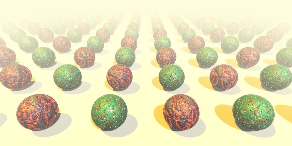
hey , Im trying to get a shader taht uses noises , which will change different colrs like this , but with all the colors
@crimson trail You want to make a shader that generates an image like the one above?
yeah kinda , and it will change like perlin noise to different colors and shapes
Where did you get that image?
you may be able to do so by smoothing out the edge values of a colorful voronoi noise https://www.ronja-tutorials.com/2018/09/29/voronoi-noise.html
Ronja's Shader Tutorials
Summary Another form of noise is voronoi noise. For voronoi noise we need a bunch of points, then we generate a pattern based on which point is the c...
do you want the distinct blobs more or the gradient edges?
@crimson trail Did you already see this page?
http://www.physics.emory.edu/faculty/weeks/pics/lcca1.html
no
its not really the effect i'm trying to get
It's literally the reference picture you gave, I don't see how I can get any closer than that 😅
if you wanna just try it for your self to start, you can sample a perlin noise and assign different colors to different ranges, i.e. [0.0, 0.25] is red, (0.25, 0.5] is green, etc.
I couldn't find a better refence image
so just used that
@sacred ether
I'll try that, and see how it gos
go's
sorry to pop in randomly in the middle of this but I have a little issue with my triplanar UV effect, it works fine but it looks like it's slightly slanted when I enable it for some reason?
here's the subgraph that handles it
Usually when doing triplanar you don't add the UVs together like that. You sample the texture/noise 3 times, each with the separate uvs then blend the results together based on the normal vector.
hm I see, going to have to think about it for a moment then in relation to using the subgraph and the branch to turn it on & off
As far as i can see my NdotH is correct here, I am trying to add specular reflection
Next I multiply by NdotL and then feed it into Pow
I have no idea , how to use the pbr graph
anyone know a good tutorial on it
How are you guys adding specular light to your custom toon shaders in Shadergraph?
@regal stag I think I've figured it out based on your advice, thank you!
@faint notch That looks correct to me. I don't think you want to multiply that with the NdotL though. I think you just need to put it into the Pow then add it with the NdotL/diffuse.
@regal stag ah, thanks ill try that - i thought Id add it with ndotl to make sure i would only get specular reflections on actual side where there is light
how do i update Gradient noise in PBR graph
"update" like, make it animate ?
yeah
Animate the UVs
softball question since i'm coming back to a project i havent touched in a while:
I'm generating 2D images based off heightmaps that subdivides it into 4 height regions, then marks the edges. So, an edge is drawn in black on the right between heights less than 0.25 and greater than 0.25, and so on for 0.5 and 0.75. Basically just drawing a line.
this is obviously pixely and aliasy, which i don't want
i've explored some SDF rendering, but have been unable to derive quality SDF fields from the edge-detected image. Here's an SDF derived from the original heightmap. It has the smooth lines I want, but is pretty inaccurate to the height
question being: how should I best smooth out the pixely image at the top?
@sacred ether I think the answer is derivatives.
I would directly sample the heightmap in the shader to draw the lines then.
If you think of it, a heightmap is already a distance field (it represents the vertical distance to the 0 level).
So with some easy maths in the shader, you should be able to get the lines you want
yeah, i had an implementation that was basically sampling values from the heightmap and transforming them into some distance away from a "band" height, e.g. 0.25, 0.5, 0.75, but that led to some pretty wonky blobs i believe. I can revisit that.
@low lichen what exactly do you mean?
I thought you meant you just wanted to make the pixely image less aliased, which you can do with derivatives.
http://madebyevan.com/shaders/grid/
@regal stag worked fine, i had to use high values though for my pow though.
ah ok, i get it now. thanks both! will work on this lol
ok , everything I find on animated uv's is in script
and I want to use the pbr graph
Here's what i have so far , it just moves
Yes, well, that's how you animate the UVs, and indeed it moves the noise. So it animates it.
ok , so in this video , is the camera moving or the noise
https://www.youtube.com/watch?v=xfqRu89ChZc&ab_channel=MatthewDoucette
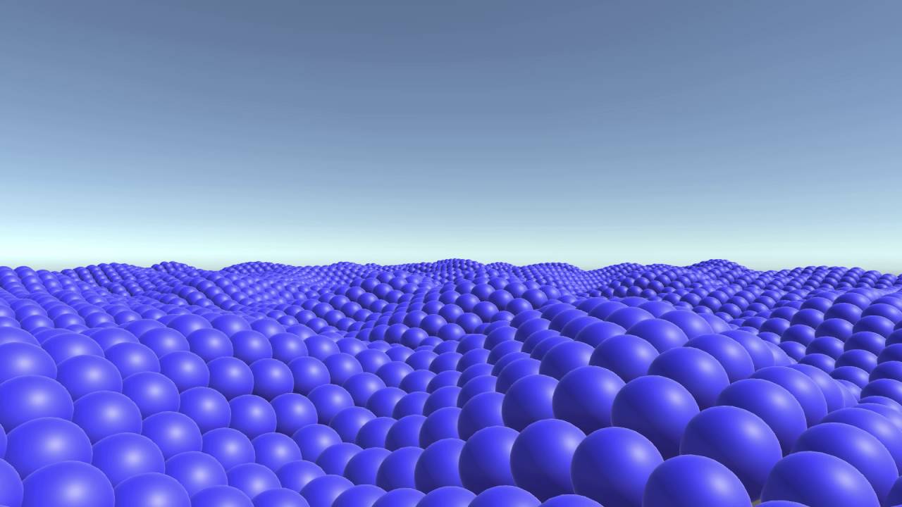
Download: http://unity3d.com/
Just playing around with Unity some more, this time with spheres and animations with Perlin Noise.
Yes, you can clearly see the shapes all going in the same direction
The camera isn't moving in that video
If you want a noise applied to UV space that animates without moving, you will need a 3D noise (2 dimensions for projection, and one dimension for time)
You can keep your eye on one sphere and see it's just moving up and down
But the noise that positions the sphere is moving in the video
ok , so how do I randomly color this noise
You can use a gradient ramp (that use the grey value to sample in a gradient)
But I guess it's not what you're looking for
Or use 3 noises with different coordinates to build the RGB color
One noise per color channel
I can use a lerp to combine them right?
technically, yes, but you just have to input them in a vector3 node
ok by default thay are all 255 , now I need to get a color node to change over time
damn , it actually worked
now I need to get a constantly changing seed
is it possible to control a HDR intensity with a vector instead of the built-in intensity?
I want this as a separate vector to control basically
@hearty wasp Do you care if the vector scales it exactly the same way, the same curve?
If not, you could just multiply the color with a vector property
I think that Intensity slider has some gamma curve on it or something, so it's not completely linear
What is shader tag queue?
Is it normal to have such drastic changes between previews when using shader graph and if not what could be causing this?
shadergraph preview
material inspector
ingame
@hearty wasp Do you care if the vector scales it exactly the same way, the same curve?
@low lichen I'll try it out, thanks
that works just fine for now, that was simpler than I thought haha
Is this a weird thing to do? Also can an unlit shader still emit light?
they don't emit light per say... but an unlit shader can still receive lighting information and can be used for custom style lighting. You can use a custom function to achieve this
@tranquil fern Not weird, it's a way to get the alpha isolated. You don't really need the Vector3 node, as it will just truncate the vector4 to a vector3 if you drag the Color(4) to the Color(3). IIRC.
Guys, what do you to apply shader to object? Do you moderate cam?
I do not understand the question
You make a material and assign the shader to the material and the material to the object
If.. That's what you mean
Yeah, this making my objects white(
That sounds like emission set to white at an intensity that's too great. But I'm a beginner so I might be wrong.
Hey guys,
is it difficulty to write a sorting feature for a urp shader so unity stops fuckingup the render order in prefabs with transparency? i either have to do that or learn how the lighting stuff in hdrp works ._.
Is it hdrp or urp? You mentioned both
Hmm, can this be happening with default Unity shaders, @tranquil fern ?
urp. hdrp has this by default
@trail dirge I don't think so. When I create a shader and create a material that uses it I don't see just white
What kind did you make? (shader I mean)
which is why i would have to stick to hdrp if i can't get it done in urp
Can you phrase your question properly then 😅
Because I have no idea what you have/expect to be honest
do you mean me @tranquil fern ? i think here are two conversations going on right now^^
No, this was for @trail dirge
ok^^
It is too hard to explain my problem((
@twilit elbow I don't think I can help you though, it seems a bit too complex for me. I didn't even know sorting was a thing
@trail dirge You're going to have to try, I think the mind reader on this discord is currently on holiday
sorting is sadly a big issue 😦 otherwise this lovely stuff happens:
I am trying to try some ways to do something looking like good shader) One minute
xD
@twilit elbow Why does that even need to be transparent? Couldn't it just be opaque?
foliage in opaque looks horrible. i use transparency to make the leaves round
I'm trying to use my own material/shader for UI Raw Image, how does it determine render order?
uhm
Do I need to specifically set Render Queue or do something else to make it work?
ooookey i switched it to opaque and i am confused.^^ i thought it needs to be transparent to get the alpha but it seems like it doesn't?
It would need to be transparent to use alpha blending. But you can do alpha clipping/cutout with opaque shaders still
@tranquil fern What shader is working? I`ll try to use that
one of those things that's probably stupid simple but I'm overlooking lol
I'm trying to make the offset go into the same direction
I assume that's something that just goes inbetween here
I've tried a few things but I'm probably just overlooking what needs to go inbetween to make the offset go the opposite direction
Negate (or Multiplying by -1) should reverse the direction it moves
huh? I tried multiplying by -1 actually
and it just made it completely black
I'll try again, maybe I screwed something else up that moment
right, the preview does turn black so I just assumed it didn't work but in the scene it does work
@regal stag again, thanks!
The preview in the Tiling And Offset node will turn black, but I'd assume the Voronoi one should be fine still
mhm, yeah, it was just me not paying enough attention
@regal stag could I dm you about something? it's not about asking more help with shaders lol
I'm trying to make the offset go into the same direction
@hearty wasp
There is no "same direction" from UV offsets on a cube. You'll have to calc those offsets in some form of worldspace "flow" vector. Otherwise, there will always be some corner that "flows wrong" from a UV mapping perspective.
I think.
You want a flow map. :2cents:
I see what you mean, but this shader currently doesn't really need that yet
plus I'm not really familiar with flowmaps, figuring those out is for another day lol
thanks for the suggestion tho!
trying to create a basic shader that creates a black outline around entities and ive run into an issue where anything rendered behind doesnt render
for reference, this is what it looks like using unity's default sprite renderer
the shader: https://hastebin.com/raw/lesoqegejo
I dont know much about shaders so I kinda just used some tutorial to set it up and then wrote my own code from there
what it looks like in scene view (as you can see they are up-right rather than being flat on the ground, this is due to how the camera is set to render)
Im a complete beginner in shaders and im just having a hard time understanding this block of code if someone can explain it to me
Shader "Custom/Fade" {
    Properties{
        _Blend("Blend", Range(0, 1)) = 0.0
        _BaseTexture("Base Texture", 2D) = "white" {}
        _OverlayTexture("Texture 2 with alpha", 2D) = "white" {}

    }
        SubShader{
                Pass {
                    SetTexture[_BaseTexture]
                    SetTexture[_OverlayTexture] {
                        ConstantColor(0,0,0,[_Blend])
                        combine texture Lerp(constant) previous
                    }
                }
    }
}```so its just a shader that blends the texture from BaseTexture to OverlayTexture
im having a hard time understanding whats going on within Pass {}
Also when does the contents within "Pass" get executed?
I think I get it?
if someone can clarify what im about to say
Im assuming the first SetTexture overlays the texture on top of the sprite, then the second SetTexture does as well with set parameters?
then combine texture Lerp(constant) previous interpolates between texture and previous according to, using constant which is the alpha?
I'm pretty sure that's surface shader syntax, which I have absolutely no experience with. It was a version of shader coding that attempted to remove boilerplate
https://docs.unity3d.com/Manual/SL-SetTexture.html this apparently
@celest lance I think this is caused by transparent sorting and depth write.
When set to transparent render queue, objects are sorted from back to front, but usually don't write depth. In your case, the spider is drawn first, the whole quad writes to the depth buffer, and prevents the character pixels to be displayed.
Looking at the visual style, if you don't need alpha blended transparency, I'd suggest to use the "AlphaTest" renderqueue, and clip the fully transparent pixels of the objects. Look at the clip HLSL command.
I have this Voroni sahder moving , and was wondering how would I color the cells , and not the outlines
One minus it before adding color
that worked thanks
how would I make every cell of a voroni cell different colors ?
I want to draw literal uniform tiles on top of a Unity terrain. How would I go about this? I can't seem to find resources on how to do it. It's mostly just how to blend materials together on a terrain
@void bobcat I think the default terrain has that, look how it's done, it has a checkered pattern
It's a checkered pattern yes, but it's not exactly what I'd want to do I guess.
I'd like to be able to draw tiles that kind of seem like they float slightly above the tile they are over and are slightly smaller than the tile they'd be over
So perhaps it's more about making verticies that represents meshes?
Maybe make a grid / square pattern and you can apply vertex offsets to them ? Kind of like in this effect (even if it's not flat)
Look at https://youtu.be/hTJqo1HeEOs?t=149 && https://youtu.be/hTJqo1HeEOs?t=711
@void bobcat np, I put timestamps for the 2 parts which may be usefull, the 2nd link shows the effect in action, where each hexagon is controlled individually
cool
Hey guys, this might seem like a basic thing, but I've had a hard time finding coherent info.
I made a dissolve shader with Shader Graph, it's cool works great; the problem is, how do I apply it to an existing object with an exisiting shader, like URP Lit Shader, but make it dissolve ?
I tried making a Texture2D parameter on my shader and using the object Texture (input by hand), which works, but excluding the dissolve, the shader makes the object look really different vs URP Lit shader.
Is there a way to apply my Dissolve to an Object without modifying it's native Texture/Shader ? Like just Adding it on top
@glad siren here , I think increase the size to two , then you'll be able to add both
@crimson trail Yeah, no, I don't think that it works like that, since 1 shader will say this pixel needs to be rendered like this, and the other one will say, this pixel needs to be Transparent, and they will override each other; maybe there is a way to configure it and use this setup to make it work, but I'm going to need additional guidance, because I was not able to make it work on my own.
I see many examples only of people using RenderTexture to pass a texture to a compute shader and some examples of Texture2D instead. Is there any difference? Should I prefer using one over the other?
@kind juniper If you don't need to render to it, then you can definitely use Texture2D instead
no, I want to pass in generated noise map and read from it. Is it a bad idea? Should I use an array of float2 or something instead?
@kind juniper You just need to make sure you upload the texture to the GPU by calling texture.Apply() if you're making it from script
It shouldn't be any slower at using regular textures. If anything, I would think it would be slower to use render textures.
I see. Thanks!
texture.apply though. Do you mean that I need to call that when I fill the color array of the texture?
Whenever you're modifying the texture in a script, you're just changing it on the CPU side. Apply() uploads the new data to the GPU.
@glad siren Convert a UPR lit shader into a dissolve shader.
I'm assuming you started with unlit.
And that's why they look so different.
You need lighting/shadow passes.
You MIGHT just be able to swap out the master node.
@void bobcat another way would be a projection decal, I use one large cube with tiled texture. Performance wise you don't even notice it, Ideally it would be nice to have it exclude certain layers so it just projects on to terrain assets. That part is on my todo list, but I believe you can purchase some assets with this feature built in.
what is SV_InstanceID ?
Whenever you're modifying the texture in a script, you're just changing it on the CPU side. Apply() uploads the new data to the GPU.
@low lichen wait, is it not uploaded when I assign it to a shader? oO
If uploaded once, does it stay there? And calling texture.Apply() applies changes to it?
@kind juniper Maybe Unity does it for you, but I don't think so
I'm specifically talking about compute shader. I'm not sure if that's different for regular shaders...
There's always two copies of the texture, because the CPU and GPU have separate memories
If you're modifying it on the CPU, you need to manually sync it with Apply()
Yeah, that's what I thought. Thanks!
@sly breach If you're doing an instanced draw, then SV_InstanceID is the index of the current object being drawn
how is it sorted ?
if i want to use a buffer as a 3d grid
something like:
Buffer [ x + WIDTH * ( y + DEPTH * z ) ] # Buffer [ x, y, z ]
@sly breach Are you drawing it manually with Graphics.DrawMeshInstanced or similar?
Or are you letting Unity batch it for you?
trying to get grid based simulation going on with compute shaders
@sly breach So you're trying to use the SV_InstanceID in a compute shader?
I don't know if that's going to be set to anything useful there
You have the uint3 id : SV_DispatchThreadID
ye and this one is inside a standard shader
to visualize the forces
but it's used for debugging only
To visualize a 3D grid? How are you going to do that with 2D pixels?
Do you want to draw a mesh for each cell in the grid?
one sec
particleMaterial.SetPass(0); //send the buffer to the material
particleMaterial.SetBuffer("particleBuffer", particleBuffer);
Graphics.DrawProceduralNow(MeshTopology.Points, 1, particleCount);
If it's just a point, then you should be able to use SV_VertexID
@meager pelican You are Right, the default shader is URP Simple Lit, and I go to a From Scratch PBR Graph Dissolve shader I made, and the lighting is missing; I didn't quite understand the steps I need to take though.
@meager pelican I am using a PBR Master in my dissolve and not a Unlit Master though, so I don't really see what I should be doing
Simple Lit (Left) / Dissolve (Right)
There is quite a color difference, how can I maintain the Simple Lit colors but add my dissolving effect ?
Wait....
You want it simple-lit?
Then don't use the PBR node, that's for full physically-based rendering.
But the problem is there's no "simple lit" master node yet. It's on their to-do list.
So it's hard to create one in SG, you'll need custom lighting information and try to reproduce the lighting calcs. The DO publish shader source somewhere.
I just haven't done it, so I can't just post some graph/code for you.
Maybe @empty oar knows something.
There are assets on the asset store, but Unity will do it eventually. Here's a thread on it:
https://forum.unity.com/threads/shadergraph-lw-how-to-create-a-simple-lit-graph.575578/page-2
You might be able to get away with blinn-phong calcs (google it) but you'll need to pass in light directions or get them from the custom node.
@meager pelican THanks, I don't actually care what it is, I was just experimenting on Unity Kyle which was Simple lit. What I actually want, is to be able to apply my Shaders, without screwing up the original object/render
You can't. 😉 😦
Haha RIP at least it's clear 😄
The shaders you use would have to be aware of each other.
Why not? ¯_(ツ)_/¯
Otherwise, like you say above, how would one know about the transparent parts of the other?
I think you already surmised this.
Yeah but I'm still novice on Shaders, so I never know if I'm out of the loop on something
The only think you could hope for is that whatever shader you used honored a mask, and then mask off the "holes" as you dissolve things. But usually, they won't.
so in the case of Unity Kyle, I'd have to be in HDRP which has Lit Master Nodes to get the exact effect, right ?
IDK, haven't tried whatever Unity Kyle is.
It's the robot man
You CAN swap materials though. So you'd only need the dissolve mat when dissolving.
😉
Yeah but the Dissolve mat, contains the base mat too right ?
No you don't have to be in HDRP, unless you want to. I mean, you have a shader feature problem, regardless of pipleline.
Or is there a way to have the Dissolve effect without having to specify the base texture ?
Sure, but it's not lit the same.
Look, we're talking about several things at once.
- How it's lit (colors normally).
- A dissolve effect
Yeah, forget the color now
Well, then just swap out the material for the dissolve material and start vanishing him.
If you don't care about colors.
Yeah it already does
But I'm passing the Texture2D as parameter to the shader
Can I not use the Mesh Renderer's Material as parameter ?
Materials are shaders.
So you don't use a shader as a parameter to another shader
Basically, shader + settings = material.
but you can swap them out, or you can "stack" them with multiple-materials.
Like you said above, though, stacking won't work in this case.
Yeah so let me just re-phrase, for my Dissolve Mat, I need to pass as a parameter the texture it will dissolve, so if I have 5 different characters, I'll have 5 differents mats, one for each character, which each refer to their appropriate Texture, I will now have 10 mats, 5 dissolve and 5 normal ones, and if I want to dissolve these units, i'll have to go to each and everyone, and swap their current material for the diffuse material, i'm getting this right ?
That's one way IF you insist on using some "stock" shader for the non-dissolve mats.
But
The other way is to use your dissolve shader for the whole thing, then you'd only need 5.
BUT, you'll have to duplicate the style you want in SG.
There's no Simple-Lit master node yet.
Do you mean like, having the shader always active, but at like, 0, and when I want to dissolve I push the alpha to 1 ?
Or however it works. Most have some slider for "dissolve amount". YMMV
So you basically have made your own custom shader materials that are "dissolve aware".
hmm, okay, but this feels really repetitive no ? like either I make 1 extremely complex shader with parameters to be capable of doing multiple effect, or I create mountains of materials to swap out ?
I can only feel I'm missing something
this doesn't feel right
OK, well maybe others will have more ideas. ;)
My inclination is to say "Welcome to shaders". 🙂
Haha you've been really helpful @meager pelican, I just feel like I'm not grasping something correctly
Well, I hope there's a simple-lit node soon. That would make your life easier. But I think you'll end up rolling your own shaders for now.
What you COULD do, if you're really adventurous and have programming experience but no shader experience, is copy the simple-lit shader source code and edit it by hand to make a simple-lit-dissolve.
But you can't do that in SG.
Where is the source code of URP default UI shader?
I think all the SRP and URP/HDRP source is on github somewhere.
Maybe here?
https://github.com/Unity-Technologies/Graphics/tree/master/com.unity.render-pipelines.universal
GitHub
Unity Graphics - Including Scriptable Render Pipeline - Unity-Technologies/Graphics
Oh I think this is what I'm looking for
https://github.com/TwoTailsGames/Unity-Built-in-Shaders/blob/master/DefaultResourcesExtra/UI/UI-Default.shader

GitHub
Unity Built in Shaders. Contribute to TwoTailsGames/Unity-Built-in-Shaders development by creating an account on GitHub.
Oof, I'm trying to modify it to incorporate bilinear interpolation for quads into UI, but it seems a bit more complicated than I thought.
has anyone got any expereince of recreating the terrain shaders in the shadergraph?
Any good ressource on Shaders usage/workflow with unity ? Nothing Shader-code related or such ?
@meager pelican Hey, I'm going to ask again sorry, but for my dissolve, if I want 10 different edge colors, I need 10 different Mat's in the end right ? I haven't found a way to only store 1 and be able to modify it at runtime, without affecting all the others; would I need to make a copy of the material at runtime, and the change it's parameters ?
I really hate the idea of duplicating stuff
Either this, or use material property blocks
@amber saffron didn't know of those, will look into it ! ty
Yeah, MPB's are per-instance variables to do what you're asking about...to change a color or something uniquely per instance, while not having to duplicate the material.
It can mess up SRP batcher though, somehow, so watch if your batches get messed up. But otherwise they're great. Needs code on the C# side, and your shader has to support it, so SG may or may not do that, it depends IIRC on the variable. If you use _BaseColor I think it is supported for instancing.
Another alternative, if you want to do it "by mesh" is to stash some value into mesh attributes, but that's a bit of overkill since you often have to do that per vertex. Like using vertex colors.
I wish unity had some user-variable, like a INT or float4, that's just per mesh that we could get our hands on somehow. IDK how they'd pass that in, but they manage to pass other stuff in...
Then we could set our own unique ID's and a CBUFFER and be done with it.
God I hate it
Why when I sample depth texture, convert values to linear and then use them to apply fog, rotating camera makes fog thinner/thicker?
More specifically, when a fragment is seen in screen corner - my shader thinks that my distance to has decreased compared to when I look straight at it
A Unity Rendering tutorial about supporting fog, for both forward and deferred shading. Part 14 of 20.
?
Okay, I figured it out
I had to divide my linear depth by dot(pixelDirection, cameraDirection)
Does anyone know why TEXCOORD1 doesn't work?
My shader has only one texture, but I need two sets of UVs, when doing mesh.SetUVs(0, ...) and taking values from TEXCOORD0 it works, but not for channel 1.
Normal and tangent as well.
Context for the question above:
I'm overwriting MaskableGraphic.OnPopulateMesh(VertexHelper vh) which generates my own mesh, while things like position/color/uv0 of vertices work, I can't seem to get uv1/uv2/uv3/normal/tangent to work.
What pipeline?
Just standard for the test project.
OK, so your shaders will have to assign the UV's to the texcoord's. You'll need to show source so we can help. If long, pastebin, but you can maybe get away with a short segment.
The names in the struct have to begin with uv...and unity will figure it out. Like uvMaintex or uv2Maintex IIRC.
It's a Shader Lab thing.
There's an underscore (looked it up in shader examples):
     float2 uv_MainTex;
};```And then in v2f you can call it whatever you want, but you assign it to interpolators:
....
float2 uv0 : TEXCOORD0
...
}
Hmm, doesn't seem to work, here's my shader
struct appdata {
    float4 pos      : POSITION;
    float2 uv_Data  : TEXCOORD0;
    float2 uv2_Data : TEXCOORD1;
};

struct v2f {
    float4 pos   : SV_POSITION;
    float3 color : COLOR0;
};

v2f vert (appdata v) {
    v2f o;
    o.pos = UnityObjectToClipPos(v.pos);
    o.color = float3(v.uv2_Data, 0.);
    return o;
}

fixed4 frag (v2f i) : SV_Target {
    return fixed4(i.color, 1.);
}
It needs to know what sampler/texture I think.
Is your texture name "Data" in properties?
Or in the sampler declaration?
Also remember UV sets start at 0
sampler2D_float _MainTex;
Use uv_MainTex
Nope.
protected override void OnPopulateMesh(VertexHelper vh) {
    var v = new[] {
        // ...
    };

    vh.Clear();

    vh.AddVert(new UIVertex { position = v[0], uv1 = test });
    vh.AddVert(new UIVertex { position = v[1], uv1 = test });
    vh.AddVert(new UIVertex { position = v[2], uv1 = test });
    vh.AddVert(new UIVertex { position = v[3], uv1 = test });

    vh.AddTriangle(0, 1, 2);
    vh.AddTriangle(2, 3, 0);
}
If I use uv0 and change shader to take value from uv_MainTex it works fine
But if I use uv1 and uv2_MainTex it outputs black.
What's test set to?
Inspector, between 0 and 1
Is this a problem specific to standard pipeline?
I'm only using standard in the test project, but production uses URP.
URP is going to be different.
OK
Give it a hard coded uv0, and a normal and tangent just to ensure you're getting the proper overload and it's working.
I haven't used that function before, so IDK.
You say if you use uv0 it works?
Yep position/color/uv0 works fine, only uv1/uv2/uv3/tangent/normal don't work.
Now there is nothing in those functions for uv2, it only has params for uv0 and uv1
Here's the source of VertexHelper, I don't see any reason it wouldn't work
https://github.com/Pinkuburu/Unity-Technologies-ui/blob/master/UnityEngine.UI/UI/Core/Utility/VertexHelper.cs

GitHub
Unity-Technologies-ui-source. Contribute to Pinkuburu/Unity-Technologies-ui development by creating an account on GitHub.
Yeah uv2 and uv3 not working is to be expected
BRB, AFK for a couple min, RL in the way....
But I have no idea why uv1/tangent/normal don't.
IDK either, maybe it's a UI system/mesh thing. On NORMAL mesh stuff, you can set multiple uv array sets. And then use uv_MainTex, uv1_MainTex...as input, then assign them in the vert() passing them in interpolated v2f struct.
Welp, I tried a regular mesh and it works just fine.
Yeah... IDK man, sorry.
All good, appreciate the help.
UI probably does something to the rendering but wow, this is kind of ridiculous.
Here's an interesting post I ran across, just FYI at this point, see post #2 https://forum.unity.com/threads/trying-to-use-uv2-without-texture.457841/
Unity Forum
Hi
I'm trying to make a custom tweak to the standard shader. For this I want to read a texture from the B channel of a texture but inputting it to the...
I did some searches on that and that seems to be what people are talking about
But disregarding that for a second, normal and tangent don't work either.
I tried using normal on a normal mesh and it works fine, but the same wouldn't work for custom populated UI mesh.
Try passing it in "custom data" like that post says in case the shader compiler is stripping it out for some damn reason. OR, maybe check the generated code.
I've had situations (not this one) where code I thought would be in was stripped. And had to make sure I used a preprocessor directive to get it included.
See normal, but not uv's.
Anyway, not that damn thing, the other one. 😉
The generated source, not the compiled source.
Oh I'm not doing uv1 anymore, I'm doing normal instead.
Is it really due to the shader?
OK, and you assigned the proper normals in your mesh gen....
IDK. I hate UI shaders. :p
Here I have both the UI mesh (black smaller square) and normal mesh (bigger square)
Both using the same material, and UI mesh can't read the normals I passed to it (shows black) while the normal mesh works.
You can try RenderDoc and see if you spot anything funky in the drawcall...it should show you what is coming in....
Maybe it's something in the mesh itself, you should be able to check that in C# side, debug.log or debuggers.
And IDK if there's an UpdateMaterial() call of some sort to ship stuff to the GPU, don't remember off top of head.
Maybe someone else will know.
Hang in there. This is that 80/20 thing where 80% of your pain comes from 20% of the features.
lol
So it's this crap that makes you want to scream. But everything has hurdles.
Ain't that truth.
I don't have access to the mesh itself though, it's in the parent Graphic class
There's a legacy mesh generation which have direct access to the mesh
Except that I can't seem to get it to work either.
Dumb question, did you remember to call FillMesh()?
VertexHelper.FillMesh is called by the parent class automatically after OnPopulateMesh
Huh. Because that example in https://docs.unity3d.com/2019.1/Documentation/ScriptReference/UI.VertexHelper.html has a call to it, and then it updates Mesh m. So you'd have access to m that way.
Tried that just now, vertices and normals look right.
So see what you're getting passed into the vert() stage in RenderDoc. It will show you the contents of the input struct for the call.
IIRC
Oh, and just a random thought...lighting uses UV sets somehow but IDK how that applies to the UI stuff. So you want to make sure if you're using lit shaders that it isn't getting trashed. But I'm guessing here.
Hmm, I don't know much about it.
I'll try more stuffs later on, had enough of it for the day.
I'm thinking maybe keep reading the source and see what it does with the mesh, maybe there's some clues.
@thick fulcrum I'll check it out thanks
I need grabpasses in urp so bad...
:/
I might need to stop using urp if I can't use them
Opaque texture doesn't cut it
I need to be able to see atmosphere of the other planet from within the atmosphere of the planet I'm standing on
And the atmosphere rendering relies on having the screen texture?
Are you distorting it or doing some complex blending operation that can't be done with hardware blending?
morning all
still trying to find ways to get a terrain-shader in shadergraph...anyone any clues?
Expose the terrain splat maps as inputs for the shadergraph, and you can use them for layering
@low lichen I grab background color and then I darken it based on absorption&scattering, plus I add atmospheric glow on top.
Expose the terrain splat maps as inputs for the shadergraph, and you can use them for layering
@amber saffron where can I find them?
what I'm really wanting to do is replace the default lit shader that terrain uses with my own shadergraph alternative which uses a GetMainLight function to alter lighting based on the word position (for underwater shading I've tweaked a shader in shadergraph to make stuff blue the darker it goes, but that won't work with the terrain itself, obviously. Unles I can apply that node to the terrain!)
Look at the terrain object hierarchy in the project window
And to apply the shader to the terrain, you just need to assign it to a material, and assign the material to the terrain in the terrain settings
it wn't let you change teh material on a terrain object
@dreamy kernel I think you can do it manually, but not in SG. So make an SG shader, copy the source code produced and then edit it from there on out. As I understand it, the pipeline supports multi-pass.
Or check custom render render passes/features if they'll work for your use-case.
https://learn.unity.com/tutorial/custom-render-passes-with-urp

Unity Learn
In this tutorial, you will learn how to use custom render passes to render a toon outline post processing effect on selected objects
aaah my apologies!
altho it really doesn't like that
all kinds of rendering glitches lol
Warning about missing tangents.
But you should be able to get something to work
i get that on other materials but this sahderraph doesn't use any tanget stuff
Does anyone know how to make fog on back side of cam? I want to have father->more alpha.
it just won't display...i'll keep trying
literally what I want to do is take ths existing terrain and just stick a extra step of shading into it
Should work 🤔
Well, then you should be able to use multiple passes in URP as I understand it. And you'd have access to the back buffer one way or another. Just do a blit to a render texture if you have to, that's basically a "manual grab pass". Or draw a full screen quad and then run a post processing effect.
I'm not exactly sure what you're attempting. But there's ways...
hmmm there's a point
if I can't use my shadergraph terrain on the terrain itself...
can I potentially use a blit-pass on just the terrain?
🤔 you could probably use a screen space projection effect, like is often used for caustics
i need to do a caustics layer anyway...
i have a shadergraph that has the MainLight & AdditionalLights functions fromt he customlighting.hlsl example code Unity provided..
which I then multiply by the depth of the water, so if it's near the surface, it's maybe the same color as normal or a little blue...but if it's really deep might be dark blue or even black...then additional lights are added in, based on their distance to the object, regardless of unerwater depth...this way if the player has a flashlight etc it will still work deep down
since i've made that sub-graph, my plan was to make a new version of the terrain shader in shadergraph, and just loop the underwater lighting stuff in..but seems quite hard/undocumented
you'd think unity would support their own shadergraph tool being used on the terrain
or even just provide a default example etc
it maybe on the plan, but probably a long way down the road.
Given your situation something which is independent of terrain while giving same results would give more flexibility. Less to maintain is always good in my book and trying to get SG terrain working will be a struggle + maintenance.
iq's shader - amazing shader skills : http://glslsandbox.com/e#68021.0
Hi, is there something like 'light function materials' from UE4?
At least in HDRP?
I want to filter the sun light intensity based on its distance to each lit objects pixel.
Hi guys, do you have any idea of what is this RenderTexture I found with the memory profiler? I googled around and found it has to do with the subshaders but i barely understand how a shader works so I have no idea whats this or if i can get rid of it.
I found it was shader related here:
http://stalhandske.dk/UnityDocs/Manual/SL-GrabPass.html
Unity is the ultimate game development platform. Use Unity to build high-quality 3D and 2D games, deploy them across mobile, desktop, VR/AR, consoles or the Web, and connect with loyal and enthusiastic players and customers.
It's likely "requested" by a shader [pass] for its needs. So the way to get rid of it is to not use the material that requested the shader. As for figuring that out, explaining that gets complicated but you could try the frame debugger or RenderDoc if you're adventurous.
It's also remotely possible it was allocated by some script, and just named "GrabPass Temp".
@meager pelican Found it
its a shader we have to render a water effect
Yeah, that's one typical use-case. It needs to "see" what is behind the water, and so it captures the screen.
thanks ! 🙏
Is it possible to have a branch not continue if it's false in shader graph? Or Is it possible to compare three values inside of shader graph?
Basically is else if logic possible?
And, uh, how do I exactly do a custom pass in urp?
How do I assign shader pass to my customly made one?
I can seem to only have one lightmode tag (or whatever it's called) per shader pass
Here's one way:
https://learn.unity.com/tutorial/custom-render-passes-with-urp#5ddc3f73edbc2a001ff7d6bc
Or try command buffers.
Unity Learn
In this tutorial, you will learn how to use custom render passes to render a toon outline post processing effect on selected objects
@azure geyser if/else are keywords in shader code. There's some caveats on if it's a good idea or not... For most intents and purposes, you're going to execute both sides of the logic from a performance standpoint, unless you're passing in a uniform value as the conditional.
If you're using Shader Graph (SG) you have a conditional and branch nodes, and also there's custom-code nodes.
Thanks for the info!
Is there a reason this is showing on an empty PBR Graph shader. It doesn't turn on or off emission so I'm confused why it's there.
@azure geyser It might make the emission be used for baked lighting
Yea looks like that's what it does. Not labelled that clearly
Jeez yeah not at all, okay thanks! I thought it was a hidden _EMISSION keyword or something
So I need to change all of the colors of about 1 million vertices every 3-5 seconds. Right now I just have each color array in memory and I use these to set the colors of each mesh when I want them to change.
each of the rectangular prisms is a mesh and each of the spider web looking group of lines is a mesh
This example is about 1m verts.
Would it be smoother to just create a duplicate of all of these meshes for each set of colors where all but the currently displaying colors are inactive?
How many unique colors do you really need?
Per frame?
Can you use a indexed lookup table for them somehow?
I would say at max there would be 10 sets of colors for each mesh
I'm switching colors every 5 seconds atm
Getting the color data isn't an issue. I have it all in a list of Color arrays.
I'm just wondering if having invisible copies of each mesh that I make visible when I want to display them would be faster than updating the colors of every mesh.
IDK how many "10 sets" is, but the idea is that you DON'T update all those meshes every frame if you can avoid it. Assign color indices and just update the color array lookup table instead (the 10 sets).
When you update meshes it will send a lot of data.
BUT, if you just want to flip between two color sets or something, then just pass a flag for "use set one" or "use set two" and store them in two sets or whatever. Let index for set 1 is x, and set 2 is y in the vert colors.
I'm still not "seeing" it so I'm rambling.
Like for every vertex there are 10 different colors it switches between
Oh so I can give the mesh more colors in a lookup table that it flips between? I will look into that
Oy, and you need that per-vertex?
Each frame random?
Or not random, but variable?
The different colors are established on start up
No global for "use set one this frame"?
So mesh 1, vert 500 gets color <blah> and that changes each frame?
I'm visualizing a neural network and the user selects a folder that contains the input images. I'm expecting anywhere from 1-10 input images.
The state of each layer is different depending on each input image.
Ah!
        {
            foreach (CubeScreen screen in screens)
            {
                screen.nextColors();
            }
}```And can it be derived by passing in "this is frame # x"?
Or are these all unique state changes that can vary?
I guess I'm stupid.
I'm trying to find a way that you don't have to update 1,000,000 verts per frame.
ok I'm very new to unity so bear with me
I followed a "minecraft in unity" tutorial figure out how to render these groups of cubes
Each cube is a pixel basically
The collection of cubes is what I'm calling a CubeScreen
Each CubeScreen displays an image
Is this AI or medical imaging? I'm assuming AI by "neural network".
Yeah I'm just visualizing what's going on inside of neural networks
It isn't doing any learning
The user uploads their trained model and I'm calling a python script to get all of these "images"
So you're colorizing "states" of some sort, eh?
At worst I would thing a triangle would have 3 verts the same color?
I realize I could just make the images into textures, but I prefer this route for now
So you could cut that updates to 1/3 of it by using indexes.
right
It's a bunch of triangles
oh I can map it like that?
with like color indices?
Yeah, I'm thinking so.
So you'd update the color table, not the meshes. The meshes would have their id's set and done.
So triangle #1 in mesh #1 would be index 0, etc. And then whatever color you want that to be could be a float4 in your lookup table.
Then you only update the table, not the meshes.
So if you had 1,000,000 verts, you only have to update 333,333 ish colors.
IDK where the 10-sets comes in.
You use the vert colors or maybe a UV set to store the index.
Or sets of indices?
I'm still confused at what you're doing, exactly.
But....trying to generate ideas.
You get an error when you try to store an array in mesh.colors that isn't the same size as mesh.vertices
Yeah.
So it has to be a setting if that option exists
Well updating 333,000 ints is a lot faster than updating 1million colors
So mesh 1, verts 0-2, is the first triangle, and would have it's value set to index 0.
mesh 1, verts 3-5 would be index 1, ... or whatever. I'm still not sure what you're needs are.
Then you'd have a color table you update per frame. A float4 array of colors.
So you're assigning the index by TRIANGLE not by vert. So each polygon as the same index.
for that triangle.
hey im sorry if im spamming the chat but ive been stuck at this point for hours now
I cant get Scene Color node to work
here's all my settings:
https://cdn.discordapp.com/attachments/757684789737160736/760969024271679558/unknown.png
https://media.discordapp.net/attachments/757684789737160736/760969278722932823/unknown.png
https://cdn.discordapp.com/attachments/757684789737160736/760969374613635102/unknown.png
https://cdn.discordapp.com/attachments/757684789737160736/760969658730938378/unknown.png


oh and this is how the shader looks like right now (on the sphere)
IDK, settings look OK on first glance. Try just outputting the scene node result, no other calcs.
Well updating 333,000 ints is a lot faster than updating 1million colors
@agile citrus 333,333 float4's (or 3's but try for float4)
And you can use UV sets for the index instead of vert colors if you want.
Yeah I think I'm going to switch to Color32 after I figure this out.
I don't see any options to use anything besides Color arrays of the same length as the vertex count.
These are specifically per-vertex colors
are you guys deep in a question right now or can I jump in and ask something new?
go ahead man
IDK, settings look OK on first glance. Try just outputting the scene node result, no other calcs.
there are no other calcs going on though? :O
its literally just the scene color output going to emission thing
I'm looking to make use of these "global" shader properties, like "Shader.SetGlobalFloatArray". How does one reference them from within the shader?
I'll be hacking something into shadergraph, ultimately, because I'm like a 5 year old when it comes to writing HLSL
but if I can cobble together enough knowledge to create a little custom node that emits values from this supposed global property interface, I'll be very happy
For global shader properties in shadergraph I think you can just create properties in the blackboard like any other.
Usually you'd untick the "exposed" option, but I don't think that's actually required.
theres no "float array" property available to create though
Ah right, missed that you were referring to the array specifically
For that you will need a custom function (and will need one if you need to loop through that array)
I'll find an example quickly, I'm sure I've got one somewhere
Ah okay. You need to use the File mode in the custom function, create a .hlsl file and pass it in.
float _Array[10]; // must set a size

void ArrayExample_float(float index, out float Out){
   Out = _Array[int(index)];
}
Would be something like that. I'm not hugely familiar with ints in hlsl so might need tweaking (shadergraph doesn't have any ints afaik, so I assume you'd need to pass it in as a float. Maybe it'll cast it automatically though?)
yeah arent they like an alias for floats or something?
I don't see any options to use anything besides Color arrays of the same length as the vertex count.
@agile citrus You HAVE to assign the same INDEX to all the verts in a polygon. Same number of verts. But you'd only do that ONCE. You're numbering the polygons.
Then you update the color table for each index (that's a separate thing from the meshes). That's one color per polygon, not repeating it 3 times.
so how would I change that first line to refer to this value that I set from C# with https://docs.unity3d.com/ScriptReference/Shader.SetGlobalFloatArray.html ?
or does it just work because it's named "_Array" ?
and I would target that same name when I make the call?
You'd change _Array to whatever you use in the C# function. So here it would be SetGlobalFloatArray("_Array", array);
gotcha. nice, that's pretty rad
its literally just the scene color output going to emission thing
@shrewd grail Well something showed up I guess. I was saying to output it to albedo, basically the sphere should vanish and show you what's "behind" it, or it will output grey or something weird.
and YOU'RE pretty rad. let me see if I can try this out quickly..
Alright ill test it out then
It kinda looks like there's some colour on the top of the sphere. I'm not sure why though. Unless the UVs being used for the scene color is messed up? It should be the Screen Pos
In your screenshots it doesn't have an input though, and I'm sure it's supposed to use the screen pos then.
He's saying scene color isn't working, but I was suggesting we prove that, as his settings look like it is enabled and he's using transparent pass.
Yeah, as far as I can tell it should work fine with those settings. No idea why the sphere would look like that though.
It kinda looks like messed up uvs to me. Like it might be sampling with the models uv rather than screen position.
do you guys get an idea of what it looks like though? like its not a static color either
its like transparent but weird
idk if that's noticeable in that pic
doing this did that ^ no difference
It should basically look like the shader has gone "invisible" when drawn correctly, as you'll be rendering what's behind it to the sphere. Might be slightly shaded with the smoothness and stuff applied on top
so no difference
like if i delete the scene color node its still that same thing
like scene color node wont affect it at all
Are you saving the graph?
ctrl+s right?
No, you have to use the Save Asset button in the top left
Ctrl+S will only save the scene
No worries
lol Happens a lot
There we go
Yeah, and the rest is lighting or something.
yeah i can fix that now :D
If you want it less blurry, you can change the Opaque Downsampling option on the URP asset too
It's best not to use too much shader because you will destroy your computer.
oh thats interesting. So my array intended array is about a million elements (its a 1001 by 1001 grid)
any ideas? 😅
would a texture be a better move?
Haven't really done something with that many elements before. A texture might be the better option
Wouldn't be too bad since you only need to sample it once anyway right?
is sampling a texture expensive? once per fragment, yeah. fragments are going to take their y position from this grid
Sampling once is fine, textures are used all the time like that anyway.
that makes sense. I just have to figure out how to write to a texture from C#
Probably create a Texture2D object and use Texture2D.SetPixels, https://docs.unity3d.com/ScriptReference/Texture2D.SetPixels.html
oh hell yes
thats excellent, this is gonna be way easier than I thought. the source array is a NativeArray
I thought I was going to have to perform an extra step of converting it into a list
although, maybe I'm wrong about what this does
because... well, I guess I would have to convert these floats into pixels in order for that to work?
Mmm probably depends on the format the Texture2D was created with
Maybe the RFloat format would work with a NativeArray<float> ?
RFloat format? iinteresting
I am seeing functions online to convert back and forth from a color32 and a float32, which is interesting
Yeah, if the RFloat format doesn't work then you might need to convert it into colours first
ah, yeah, RFloat is a scalar texture, thats conceptually exactly what I need
so in this case I can use the texture nodes and properties that are already in shadergraph, right?
hypothetically
Yea
You mentioned earlier about fragments taking their y position from the texture right? Do you mean displacing the vertices though?
yes
Then make sure when you sample it in shadergraph, use the Sample Texture 2D LOD node, as the other one can't be used in the vertex stage.
oooh, great catch
does LOD have to do with how granularly it's interpolating values?
LOD is to do with the texture's mip maps, which you probably don't have any anyway
Yea 0
There is also point vs billinear sampling that you change, I think either in C# when setting up the texture, or override it in the graph with the SamplerState
want to see what we're building?

thats all physics, no shaders involved
its all a big ole runtime array of wave positions
so if I can map this sucker into a shader, stuffs gonna get real cool in a hurry
doesn't seem like its gonna let me sample RFloats from this thing.
considering you have no choice in the output of the Sample Texture 2D LOD Node
its a Vector4 and that's that
Ah cool, like a "pin-table" kinda thing
yeah haha, thats how it ends up looking without shaders
It should just be the the R output I think?
ohhh interesting
what does this mean, and how do i fix it
You need to have URP properly installed into the graphics settings https://docs.unity3d.com/Packages/com.unity.render-pipelines.universal@8.2/manual/InstallURPIntoAProject.html#adding-the-asset-to-your-graphics-settings
do i have to create my own scriptable render pipeline asset?
If you didn't start your project as a URP project, yes
Then you should check the graphics settings to see if it's assigned properly
Then you'll have to create one. I'm guessing your project either wasn't actually a URP one or you deleted the asset when you opened it.
Either way, you can create one manually
oh, when i created it there was some template scene and stuff that i deleted. might have accidently deleted the shader
how would i be able to make those bubbles inside?
would using particle system instead of shaders be an easier solution to making them? If so, how could i make the particles look like that?
i know i would probably be using fresnel and some refraction to make the bubbles but then how would i generate randomly or something
@shrewd grail so, Im not an expert, but I believe this is typically done by sampling a scrolling noise texture, not actually generating random numbers. you generate random noise and store it as a texture, and then multiply something's position by time and use that to sample the noise
waiiiit a minute. Sampling textures is done via a number from 0 to 1 isn't it :/
not by 2darray indices.
I do have an explaination by the person who made it but I couldnt comprehend it 😂
Hold on lemme link it here in case anyone could lay it out for me in simpler words
https://blenderartists.org/t/gel-shader-or-liquid-simulation/1171933/13
Read the messages by pixelgrip
He kinda explains it but i didnt get what he tried to say

Blender Artists Community
how about that one here it is a combination of 3D model and refraction I think
He's commenting on Blender specific shaders anyway.
In general he's saying use a particle system for the bubbles and a glass shader on that (assume that does refraction of some sort).
They already had the cylinder of colored liquid with a top and bottom "slice" on it and an active area in the middle.
Things to search google for: Unity, refraction, bubble, glass, shader, example.
I don't think they're doing any real liquid simulation (no waves or whatnot, no flow if the container is broken).
Or you can check this out:
https://www.youtube.com/watch?v=dFv8lM-kS4E
But it might be hard to follow if you're new to this stuff.

Lately, our twitter feed was literally full of bottles containing liquid directly from the last chapter of Half-Life (Alyx).
A lot of good talented creators made their version of this cool liquid effect.
Today we'll create our version of it on Unity.
Ronja's Stencil article:...
The guy named:pixelgrip did it in unity tho
Combination of shaders+ particle system i think
But ill look at that vid thanks
Also i dont really need liquid similation
I want my character to basically be made out of gel
So he'd have moving bubbles inside with some refractive shader on him
I have a question though, how would you make the particle system look like bubbles 🤔 (kinda off topic from this channel i guess)
Also particle system sounds better performance wise i think?
The vid is mostly about liquid sim, so you can skip it, no bubbles!
But as for the particle system, I'm pretty sure his post was talking about blender particle system but maybe not.
Anyway, you can do the bubble a few ways. The particle system would refract light from the scene. Do that goggle search and find out how to do a custom bubble shader that refracts light. There's many examples IIRC. Publishing all that here isn't very practical and I don't have one handy.
The bubble might be a mesh, or it might just be a quad with a circle on it, and a special shader. I know you'll find them if you go looking for it.
Well i already do have a refractive shader :D
You'll probably nee d a reflection probe and reading it in a refractory way.
Well, use that, and try a mesh particle system with spheres!
Emit from a circle on the bottom.

You can fake the whole thing too with an animated (tall) texture that wraps in the Y direction (seamless bubbles), and just burn in some reflections, but that's "cheap" and won't really refract.
Refraction would ?invert? it.
Ah ok
You might cheap that out too by inverting the Y UV properly within the bounds.
Well then its super late here
Thanks for all the help, cant wait to try this out tommorrow :D
Byee
I'm trying to add a shader material to a UI image and use a mask
but unity says Material doesn't have a texture property '_MainTex'
@final hollow it's fairly simple to convert a 2d array to 1d, there's examples on the net. Not looked back on the whole conversation, but from the vid what your doing looks a lot like Matthias Müller-Fischer's work, specifically the 2008 GDC using a heightmap to simulate water (pipes sim). You can easily push this to a compute shader if that's a possibility for your target platform.
Repost
I'm overwriting
MaskableGraphic.OnPopulateMesh(VertexHelper vh)which generates my own mesh for UI, while things like position/color/uv0 of vertices work, I can't seem to get uv1/uv2/uv3/normal/tangent to work.
Just wondering, does shader graph have something equivalent to UE4's Material Parameter Collections (https://docs.unrealengine.com/en-US/Engine/Rendering/Materials/ParameterCollections/index.html) where you can define global parameters which effect multiple material instances at the same time, or is this something that can only be done through code? Basically I'm wondering if it's possible to make it so that some shader properties are global and when you adjust the slider it effects the values for each material that uses the shader, like a slider for snow coverage for example.
Using a pbr graph, which node do I need to move between two colors based on a value between 0 and 1?
Lerp
Ofc.... Sorry, thanks.
I have a quad that plays video, and I want to make it hologram style. The input is a Texture2D... Which graph would be best for that? I tried the unlit master but I can't pass in a texture anywhere.
Master node isn't really important for using a texture, you just need to set up a Texture2D property in the blackboard and then use the Sample Texture 2D node to sample it.
I'm an absolute moron.
I thought "Sample Texture 2D" would be an example texture
I didn't want an example, I had my own. haha oh no
So then which of the graphs would perform best? Or do they perform pretty much the same?
I'll have about 250 of these running around the scene so I want to make sure it doesn't start a fire
The PBR one has to perform lighting calculations, so will be more expensive than the unlit one. For a hologram effect you probably don't need that lighting so I'd go unlit.