#archived-shaders
1 messages · Page 172 of 1
it's using the metallic texture's alpha channel for smoothness information
Cyan is too fast for me
Ah, great, thankyou, so it seems that i am sending metallic info to the smoothness and the smoothness info to the metallic
Hehe iz ok, you are both ninjas!
(Please recognise a sincere thankyou here tho, for both of you, as i have been struggling with this for as long as it has taken me to build an entire mutable noise field system designed to create the above image from fractal equations...)
(Over a week)
@regal stag @amber saffron
(note the 2 million vertex count in the bottom left :P)
This is to much weird for my brain to interpret
Its... a customised fractal. It is linked in its behaviour to a mandelbrot, but the equation is different, constructed by a friend on mine
I rigged up a randomising capability... and this is one of the more interesting resulting shapes.
I think I lost it in the conversation, but how are you generating the mesh from the fractal ?
Oh, its a marching cubes algorithm.
Certain ways of rendering fractals, especially 3D morphing ones, have always made me feel uneasy. Kind of like trypophobia, but I have no problems with holes like that. It's just fractals. Your specific one is fine though.
I basically merged a fractal equation with the idea of a grid based noise field, then included an algorithm of my own which explores the surface of any shape in a noise field given a sample boundary and a noise grid, except the key is that the noise grid remembers its own samples and doesnt provide them until the pathing algorithm asks for them.
So, when generating a shape of around 1024 cubed grid cubes, then you only end up sampling one line then finds the first surface, then the rest of the work is basically sampling every "block" within 1 block of the surface, and then discarding the work for the other 95% of the cubes, so it can produce fractals of a massive size, compared to usual computation methods.
Is that in C#? Or is it compute shader stuff?
Pure c#
Not one compute shader - thats a limitation imposed by my intention to produce the game for android.
It kinda has the calculation aspect seperated from the noisefield tho, it can slot any function that follows the input-> float3, output->float format.
A more common shape... the traditional mandelbrot! Heheh
Oh, now I see what was also bugging me
You should try to smooth those marching cubes
unless you explicitely want this angular shape
I've got a quick question about how to approach something in Shader Graph
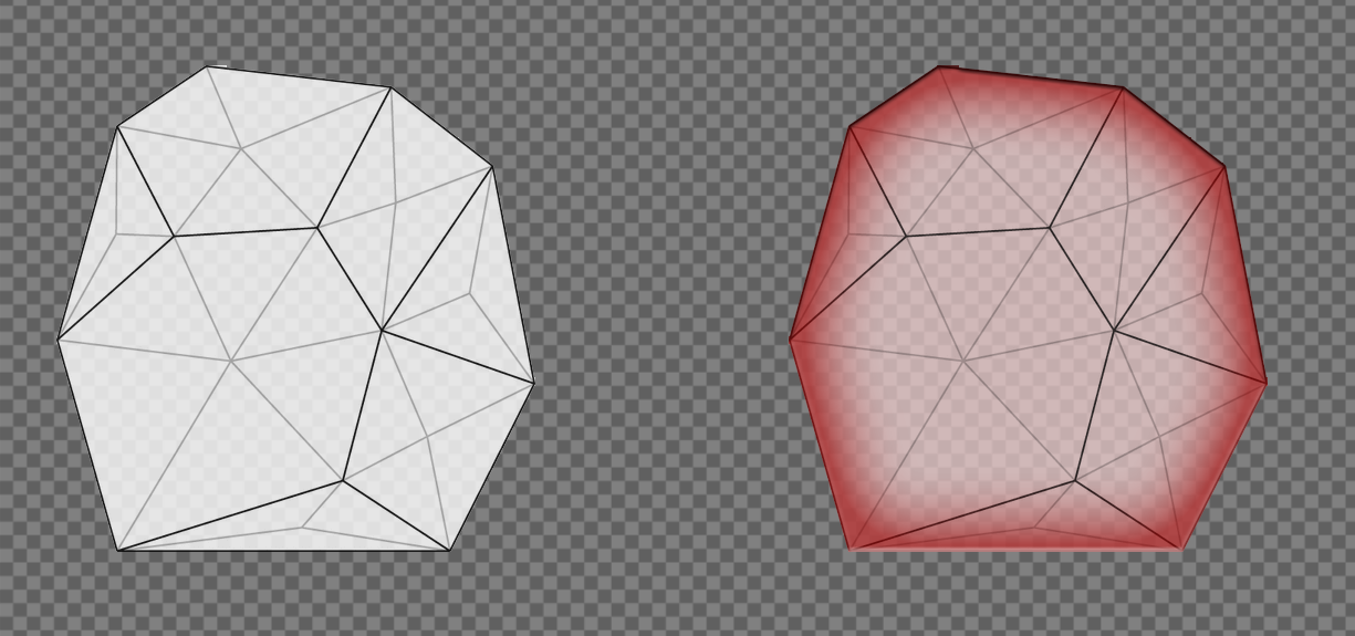
I have this procedurally generated mesh:
I'm working with the Universal RP, and I need a Sprite-Lit shader on it that will have an edge "fresnel" effect
I've found this thread on Unity Forums, but it didn't really come to a clear conclusion https://forum.unity.com/threads/need-tips-on-creating-inline-glow-shader-for-2d-polygons.506814/
Unity Forum
So here is what I am trying to do. Given irregular polygon (on the left) I would like to be able to create a shader that would resemble Photoshop...
Here's a little diagram of what I'm tried to achieve:
Any help would be greatly appreciated. Thanks!
Since it's already procedurally generated, you should look into generating something to tell you where the edges of the mesh are, as the shader has no way of determining that. Basically, for each vertex on an edge, assign a vertex colour, or use a uv channel. 1 for edges, 0 for anything interior. Those should interpolate across each triangle and produce a gradient similar to that.
that wouldn't work on 1 thick square strips tho :D
I need to have it work on 1 thick square strips as well 😰
or wait your code already generates it 2 thick
That's just Unity's grid
Just generate half squares then
Yeah, I should just create 4 squares for each one and that solves it
yeah but make the triangles in an [X] shape so the blending wouldn't look weird
on the corners
Alright I'm going to try the vertex color thing
Got the edge detection working! Time to do the vertex colors
@regal stag@cosmic prairie How does one implement basic vertex colors in the shader?
This is what I have at the moment, but the mesh is invisible:
Maybe the alpha component is 0?
Let me see
@regal stag Color.red, Color.black, etc, don't have a 0 alpha component? Or do they? That's what I'm using right now for testing
Nope, I just check the documentation and they have an alpha of 1, so that's not it.
Are you sure it's a shader problem and not the mesh generation?
Let me see
I'm going to try disabling the vertex color part of my code and see if that fixes it
@regal stag Alright, it's something with the vertex colors. Removing mesh.colors = new Color[vertices.Count]; and my other vertex color code fixed it
You probably don't want to set the mesh.colors directly to a new array like that. I'd store the array in a variable, then set the colours for each vertex, then apply it to mesh.colors
Alright, let me try that
I got it working!
mesh.SetColors worked
@empty oar Thanks so much for all the help! Looks pretty ugly at the moment, but I can work with this
Nice, you should do what @cosmic prairie suggested and use a X shape for the vertices. That way you can apply red to the center vertex here to fix the white triangles (edit, ignore my image, see peter's one)
I was actually thinking of this, (middle white) otherwise it would be jagged on straight sides, no?
or it may be just late and I need some sleep xD
I think it would be the same, I could be wrong though
did it post twice?
Yea
crap :( mobile data be like
Both of these with the center vertex would also fix the issue with not having edges for 1 unit tiles, as discussed before
the more I look at this the more certain I get that it will be somewhat jagged
I'm swear I'm not going insane xD
Yea you're right, it needs to be like you drew, I wasn't thinking enough about how it would connect to neighbouring tiles.
Or stencil it in one pass, make it smaller by some calc'ed %, and draw it clearing the stencil in another pass. The resulting stencil has the "inline" around the edge assuming it has no holes and is convex. Kind of like outline methods. A post process would "glow" it too if you wanted.
Stencil passes aren't too bad if you mask off the color channels and just write the stencil. YMMV.
2cents
I'm currently working on doing an X-shape, @grave wave suggested it as well
hey Carpe, do you know anything about messing with rendering lights in the default pipeline?
like, if possible, I'd like to mess with the rendering per light to actually inject my custom shadow info
can someone suggest me a tutorial that will help understand the meaning of shaders that you use on materials for unity?
example: when you draw something in white in photoshop with a black background, you set the material to alpha blend so it cancels the black color and make it transparent, how does that work? and what do other shaders for materials do?
please mention me if you answer thanks!
@vital jacinth Shaders are bits of code that generally run in parallel on the GPU and render things in different ways. Each shader has different parameters. In order to use a shader on an object, you have to create a material using that shader and set the parameters. A material stores two things: a reference to the shader that it uses and that shader's parameters. For the example you gave, look up "chroma key shader." Keep in mind that I'm a complete noob in terms of shaders, so I'm not the one to ask for anything more than the simplest things! 😅
Hey Im having some trouble with a laser I made
in the editor it is woring fine , but when playing in the editor its not
In editor
In editor game view
I think it may be something in Project settings
How do I create new material at runtime in URP ??
        redMat.SetColor("_Color", Color.red);```
Where I can find name references to the shaders as this one doesnt exitsIt probably needs to be "Universal Render Pipeline/Lit", as that's what at the top of the shader file.
Oh damn thats long
You can also find all the properties listed there, like _BaseColor, which I think is used instead of _Color
Sweet thats workin @regal stag Tahnks!
@nimble cloud IDK man, I just got introduced to it by you!
But I suspect you'd have to use custom shadow caster passes and command buffers for other passes, and/or post processing passes.
What unity does is build a shadow map per light as I understand it. ?But there's exceptions for things like sphere lights? where only things within the radius are rendered or something. And you build custom shadow volumes per light, so IDK if you can hijack that or not.
Maybe more lighting guru's will pipe in here.
I suppose the worst case is you turn off shadow casting and run it all "manually" but wow.
In SRP you can download the pipeline source (at least the C# part of it) and then customize it from there. But that's not what you asked about.
hello, is it possible to do vertex displacement from a heightmap sampled from a texture2Darray in shader graph? The graph isn't letting me connect the nodes coming from "Sample Texture 2D Array" node to the vertex position. Only when i use "Sample Texture 2D LOD" node, does it let me do it. However, the "Sample Texture 2D LOD" is per single texture, not per texture array which is what i require.
You might need to use a custom function, using the SAMPLE_TEXTURE2D_ARRAY_LOD(textureName, samplerName, coord2, index, lod) macro
@regal stag thanks, i'll check that out
is there a way to write a mobile only conditional in my shader and have it work in the editor when my build target is set to a mobile platform?
#if defined(SHADER_API_MOBILE) appears to work in builds but not in the editor
Isn't that what the Graphics Emulation option is for? Though, I don't think you can turn that off, so you'd probably already have that set
Well you can create your own define.
https://docs.unity3d.com/Manual/SL-MultipleProgramVariants.html
Then test for it
#if defined(SHADER_API_MOBILE || FORCE_MOBILE)

@low lichen that was my thought, since graphics emulation is running i just assuemd it would work
@meager pelican i would then conditionally enable FORCE_MOBILE from a script somewhere?
What about the more specific mobile platform defines? Are any of those set?
nah, doesn't look that way
graphics emulation is set to GLES 3.0
and
#if defined(SHADER_API_GLES3)
    float lightPower = 5;
#else
    float lightPower = 3;
#endif
is going with the 3
I've recently found a way to possibly do what I wanted to use multipass shaders to do in URP so I'm going to plan on doing that @meager pelican, since the legacy render pipeline has no documentation on how to mess with it
@onyx cargo Yes.
hey guys
im working on a replacement shader rn and i really want to know what render type is the skybox?
@real gorge The built in shaders appear to use the RenderType "Background".
Tags { "Queue"="Background" "RenderType"="Background" "PreviewType"="Skybox" }
Thanks @regal stag 😄
I'm making an atmospheric shader
Since I want it to occlude planet surface and I also want to see out from within it, I've turned culling off
But now backside and frontside colors add up when viewed from the outside
So, uh, how do I fix that?
Can I sample depth texture in URP shaderlab or something?
Are you using a colormask?
Also, Landon, the only way I can think of to make that PS render on top of everything is changing it from rendermode - worldspace to rendermode - overlay.
Fair point. Anyways, what I'm going for here is a shader that is COMPLETELY unaffected by everything (Lighting, other shaders, particles, etc.) I've got most of that covered, but there are still things that render over me.
@grand jolt Well thats possible for the game view but i don't know if that's possible for the gizmos in the scene view (to draw over them.) or if it is... why would you need that? what is the end goal here? what's the user story?
is this some custom editor UI you're building?
@grand jolt You've asked me? No, I don't even know what they're used for
The end goal here is $1000 lol, a friend of mine and I made a bet that if I was able to produce something that can't be rendered over, they owe me $1k.
Will DM you the actual shader file so you can give better insight. (I edited one of unity's built-in UI shaders.)
Can I sample depth texture in URP shaderlab or something?
@dreamy kernel https://docs.unity3d.com/Packages/com.unity.shadergraph@8.2/manual/Scene-Depth-Node.html
But it's shadergraph
@dreamy kernel yeah gg
there's no shaderlab API for URP or HDRP yet
so you can have at it but you're on your own and will have breaking changes as the API is developed
there's a big official thread about it on the forums
The scene depth node just samples _CameraDepthTexture. You can do that in code too, or use : https://github.com/Unity-Technologies/Graphics/blob/master/com.unity.render-pipelines.universal/ShaderLibrary/DeclareDepthTexture.hlsl
Oh, thanks a lot!
yeah go for it just FYI
But, again, is there no simple way to only render one side out of two unculled ones on a transparent shader?
So they don't add up
The end goal here is $1000 lol, a friend of mine and I made a bet that if I was able to produce something that can't be rendered over, they owe me $1k.
@grand jolt that's still too ambiguous of a definition
If they don't write to depth, there's no information to sort them afaik
Unless you do something like two separate shaders with different queues
Well, I'm just a beginner in all that shader stuff
@dreamy kernel then I'd recommend shadergraph
there's a custom code node at least @dreamy kernel
Better explanation is I want to make my model/mesh render in front of everything (Like Z-Test but stronger) I'm already using Z-test, high render queue, grabpasses, stencil etc.
Nodes are awful in big physically-based shaders
You probably can by writing code in the Custom Function node. (it allows you to include a .hlsl file in the graph).
I see, thank you
I think I'll look into this after I'm done with this shader
I've been working on it for couple days now, I ain't going to abandon it unless I get firmly stuck
The little red character in the background is doing what I want it to do, but there are still things that can occlude it or render in front of it.
Better explanation is I want to make my model/mesh render in front of everything (Like Z-Test but stronger) I'm already using Z-test, high render queue, grabpasses, stencil etc.
@grand jolt maybe look into camera stacking?
The only limiting factor here is I'm restricted from using Canvas components.
That was the only rule, I can't use any Canvas components.
Oh, by the way, camera stacking is URP-only, right?
Pretty sure you can stack cameras in built-in too
URP's is more optimised though I think
If this turns out to be as simple as stacking cameras I'm gonna be pissed lol
Lol
I've been working at this for like a month aha
i think there is a way with built in RP but there's better docs for it with URP it seems? : https://docs.unity3d.com/Packages/com.unity.render-pipelines.universal@8.2/manual/camera-stacking.html
spells out your exact use case
render a 3d model over UI elements
So with camera stacking I can make it near-impossible for something to render in front of me?
I'd assume you could always just add another camera to the stack
Anybody have an example setup they could show me or throw together quickly? I'm not sure how this would be best setup.
Like with making the model the primary render target.
@grand jolt i'd just search the web for camera stacking tutorials / examples at this point
they are out there
I think for the built-in RP it's just the "depth"? option on the camera component
(and setting up appropiate clear flags if you don't just want to hide the other camera completely)
I'm not sure camera stacking is possible with the version I'm using.
There's no stack section for cameras for me.
What pipeline are you in?
Right okay, it's usually referred to as "built-in"
Ah fair enough
Unlike URP it doesn't have a stack, It's controlled by the "Depth" value.
I'm not sure how this would work for like pseudo-camera stacking
I'm not sure what you mean
If I can't do camera stacking normally, I'm wondering if there's any way I can achieve the same effect.
You can do camera stacking, It's the depth value I just mentioned
Okay this is definitely doing something.
Ah but it's larger values that are drawn ontop, I had it the other way around
It's a float, so I'd assume the max float value would be allowed for the "most-top" camera. But even then, I don't know how cameras with the same value are sorted.
So set up like this?
@grand jolt Here, this tutorial seems to go through the idea : https://www.youtube.com/watch?v=bbnVpPiQ_rU
One additional thing it doesn't mention is this setting on the camera.
I would assume cameras with the same depth value might be sorted by their order in the hierarchy/scene, but no idea if that's the case or not.
If it is the case though, it's going to be pretty much impossible to prevent another camera from rendering over yours
And there's also ways of rendering over a camera from script, using something like Graphics.Blit
Can I include UnityCG in URP shader?
Technically you can, but you shouldn't. If you include UnityCG, you can't include the files from URP's ShaderLibrary as it redefines a bunch of the same stuff
URP shaders should also use HLSLPROGRAM rather than CGPROGRAM, as the CG one also includes some other files, again replaced by the ShaderLibrary
LinearEyeDepth is also in the ShaderLibrary. I think it takes a second param of _ZBufferParams too though
Yeah it's in the pipelines.core Common.hlsl. If you include URP's Core.hlsl that will automatically include that along with a bunch of other stuff that's commonly used.
You'll need to stop using UnityCG functions like UnityObjectToClipPos though too. URP replaces it with TransformObjectToHClip. Or you can do something like VertexPositionInputs positionInputs = GetVertexPositionInputs(IN.positionOS.xyz); OUT.positionCS = positionInputs.positionCS;
to obtain the position in different spaces. positionCS being clip space, positionWS for world, positionVS for view, positionNDC for normalised device coords, aka basically screen pos.
lemme know if I should post this guy elsewhere please: I'm trying to create a VFX shader graph for the first time- I'm using the LIT visual effect master node.. but no matter what I do.. the preview output is just black. I even set the color directly to white- but preview remains black. (and shows nothing when used in my VFX)
Thanks a lot
Yeah, it's not like I've been using UnityCG anyway, I'm just a beginner
So, it should something like that, right?
Not really sure what viewLength is, but basically yeah. I would probably replace tex2D with the macros that URP tends to use as well, though I don't know really know if it's required.
viewLength is viewVector length, I've seen LinearEyeDepth multiplied by that in some repo
So I thought it was right way to go
What macros URP uses?
Usually textures are defined in URP using
SAMPLER(sampler_TextureName);```
(outside the function, like replacing sampler2D or whatever it is) and then sampled via `SAMPLE_TEXTURE2D(_TextureName, sampler_TextureName, uv);`

It basically means that it uses the appropriate dx9 (tex2D) or dx11 (separate texture and sampler, texture.Sample(sampler, uv) syntax for whichever is supported on the platform. (At least that's my understanding)Specifically if you want the depth texture though, you could do :
#include "Packages/com.unity.render-pipelines.universal/ShaderLibrary/DeclareDepthTexture.hlsl" then use the SampleSceneDepth(uv) function.
https://github.com/Unity-Technologies/Graphics/blob/master/com.unity.render-pipelines.universal/ShaderLibrary/DeclareDepthTexture.hlsl
Nice!
Really satisfied with the result; all the effort was really worth it
Looks awesome!
@regal stag
Yeah, DeclareDepthTexture.hlsl conflicts for some reason with my project
Oh, actually, nevermind
If you are using the include, you'll want to remove any definition you might have made with sampler2D _CameraDepthTexture or the TEXTURE2D(_CameraDepthTexture)
I'm just dumb
I forgot that I added this specific sampler2D like 40 minutes ago out of despair
Yeah thx
Sampling scene depth seems to give me a constant value across the entire screen
SampleSceneDepth is supposed to take in uv coords ranging from 0 to 1, right?
Firstly, is the depth texture enabled in the URP asset?
Lol, also secondly, what uvs are you using to sample it? If you are using the model's uvs that's not the intended coords as the depth texture is in terms of screen position.
Nah, my uvs are alright, I've checked them visually
I'm using ComputeScreenPos for them
Oh
Uh, it's not 0-1, is it..
Ah okay, wasn't actually aware there was a ComputeScreenPos in the URP ShaderLibrary. I usually use the positionNDC from the VertexPositionInputs positionInputs = GetVertexPositionInputs(IN.positionOS.xyz); thing I mentioned earlier. It's the same thing though.
You need to pass that screen pos into the fragment shader and divide by the w component though. So float2 uv = screenPos.xy / screenPos.w;
Yeah it's still not really working for me
Maybe it has to do with how I test this stuff
I have a ZTest Always Zwrite Off sphere placed behind some stuff
And it additively outputs light based on current screen depth value
Well, my head hurts real bad after trying to get this all to work, so I'll probably head to bed in like 10 minutes
By depth, what value are you trying to get? The depth to the object that you are rendering, or depth to objects behind it?
Oh right, it's ztest always
It uses render queue of transparency+600, idk if it matters
I probably need to read how rendering engines actually work
The next time I decide to write a shader
Should be fine. It probably needs to be in the transparent queue to make sure it can obtain the depth texture at the right point (as it's created after opaques)
It might be a good idea to just output the depth value directly and see what the result is, make sure it changes when moving around another scene object. (maybe raw, or converted with Linear01Depth rather than eye, or maybe eye but divide it by a large amount to bring it into a better range).
Return it as a colour in the fragment. return float4(depth.xxx,1); or whatever
If the sphere is the one with this shader on, I think you should keep it transparent
But other objects will need to be opaque in order to show up on the depth texture
Somebody freaking shoot me
I've set "depth map" enabled on a wrong URP asset
Okay, now it works
Now I head off to bed
Night!
Night
anyone online?
@dense yacht if you have a question just ask it
How do you sample a 3D texture in the vertex shader?
I am trying tex3Dlod with no luck.
Okay, now that I post here it's working 😉
Yeah, you have to post here first. Then it works.
It "knows"...
It's kinda rigged. 😉 :p
what is LOD for?
level of detail
it lets unity render objects far from the camera at a lower detail/resolution
to save resources while not having any noticable effect
@dense yacht
does that help
kkk
hello, does anyone know if it's possible to zoom in/out in shader graph when dragging a value out of a node? The scroll wheel doesn't work when you have it selected, it's quite annoying to zoom out to see where you need to drag, click on a miniscule value icon to drag it and then put it on a miniscule connector to connect the nodes.
Idk, i find it annoying too. I usually drag it into a temporary node / preview then moving that is a bit easier
hello, are there portal-like nodes in shader graph which would allow you to connect a value from a node to the portal node which would then be used to create any number of outgoing portal nodes of that type? Similar to what you can use in MapMagic.
Not currently no, It's probably something that's been suggested by others to be added though. (I know Amplify has a local variable thing which is similar to what you describe)
That said, it doesn't appear to be on the roadmap. Maybe you should submit it as an idea so they know it's wanted. https://portal.productboard.com/8ufdwj59ehtmsvxenjumxo82/tabs/7-shader-graph
Is there a practical difference between step and round here?
maybe in terms of performance?
render like 500 planes in front of the camera and test it out :D
step lets you adjust where the value changes. I checked the hlsl docs and it's doing a greater than comparison between in the edge and the in
the same docs don't even say how they perform rounding, but it's probably faster
Here's some (old) docs for reference...see sample implementations.
in either case those are both very fast compared to a lot of other junk you could do in a shader
how do i use custom shaders with urp
im trying to get this shader to work https://answers.unity.com/questions/1660559/how-could-i-prevent-transparency-overlapping.html
Unity is the ultimate game development platform. Use Unity to build high-quality 3D and 2D games, deploy them across mobile, desktop, VR/AR, consoles or the Web, and connect with loyal and enthusiastic players and customers.
Anybody know if it's possible to write custom depth values to the depth buffer from a shader graph (in HDRP)?
Why does my post-processing not work? I'm using URP, and it works in the scene view, but not in-game. My PP volume is global, so it should affect all cameras?
is this the default URP post processing stack?
I guess check quality settings, perhaps your game view or target platform doesn't support them?
what is the best way to have the opacity of pixels decrease the further away from a gameobejct in a custom shader>
So I had a toon shader I created in Unlit Graph, I wanted to it receive shadows so I made a PBR Graph version instead and used the light calculation output for the emission to make the object light itself.
With point lights however, it still has the regualr lighting on top of toon lighting
Is there a way I can prevent the regular light calculations to occur on the surface?
@urban pendant i think they did an official tutorial on toon shading with shadows, that might help
i think the video showcases a bunch of little monster things running around for context
there are at least two by the unity youtube channel that I can think of with toon shading + shader graph
Is there an API to add and substract pixel information from 2 bitmap textures?
Im traying to avoid calling GetPixels and then doing a huge for loop
@urban pendant You can get shadows with the Unlit Graph but you need to either figure out a way of defining those keywords or bypass them completely. I have a small twitter thread going over one method that I've used - but it's a bit hackish and unsure if it still works. https://twitter.com/Cyanilux/status/1240636241252679681
Near the end of that thread I also mention the bypassing keywords, basically involves copying the shadow calculations into the custom function. e.g. Something like this : https://github.com/ciro-unity/BotW-ToonShader/blob/master/Assets/Shaders/CustomLighting.hlsl
(This specifically doesn't bypass the keywords for shadow cascades so will be glitchy if they are enabled though, the last tweet in the thread goes through a possible fix for that).
I'm trying to make an unlit graph that takes a color and slowly pulses in opacity. It seems however (in the Main Preview) that alpha doesn't have an effect. Is this because it's unlit?
The alpha will only affect transparency if you click the cog on the master node and switch it's surface type to Transparent
That's what I forgot!
Thanks a lot
I'm making a cell-highlight shader. I have a grid, and you can select a cell to do something in. I think it'd be cool if it glowed a little bit around the edges. That's emission right?
Emission in the PBR master is basically an Unlit layer added ontop of the lit surface. If you use bloom post processing it can make it glow more - but that doesn't require emission and will work the same with the unlit graph too.
I don't know what PBR master means, but I selected HDRP unlit graph
Ah okay, I don't really know if HDRP treats things differently
It looks like emission does contribute to global illumination but I'm not sure if it's realtime or only baked
Thanks 🙂 I'll play around with it a bit
Love your Twitter content and all the tutorials btw, thank you, I'll check that one out too soon!
Is there an API to add and substract pixel information from 2 bitmap textures?
@serene creek
You can probably do it all on the GPU, one way or another. If that's what you want. But your question is ambiguous. Do you want to add two textures together and get a 3rd one back out? Or what?
Are you asking how to manipulate two different textures independently?
If you're adding two together, you can create the empty 3rd one, and then run a pass over them to accumulate the other two into it. Compute shaders, if you can support them on your platform, would work well.
And if you do it on the GPU, you're best off planning NOT to get the results back on the CPU side.
2 cents.
@meager pelican Thanks, what Im trying to do is create a mask texture from multiple masks textures
Each time a mask is added, the black pixels will be added to the result texture
the way Im doing it now is iterating trough each pixel and adding it to the result mask texture
on a 1024 texture this is thousands of iterations
since Im doing it all on the CPU
once I have my result texture, I set it to a socket in a shader as a cutout texture
I would like to improve this if there is an API that can add pixels from two Textures and return the result in a more optimized way
There's no "API" that says "add these two textures together" that I know of. It's a shader, where you code the math operations. Maybe there's a canned "blit" for additive operation on a shader, IDK. But you could write that easily enough.
We'll have to ask the GPU guru's here what happens if the GPU resets and loses context, but otherwise you can keep the results on the GPU. But if you need to save it, then compute it on the CPU, or find a way to read it back from the GPU (ugh).
But first I'll ask you why you need to do it that way?
Why not just read the two textures, and then based on the TWO results, use that as a mask. Why bother combining them at all? Does it accumulate or something?
If so, since the source is the CPU, you may as well accumulate it on the CPU since you're uploading 1024x1024 result either way....either to add it, or to update the one that's there. It's still the same size "upload" to the GPU. And if you had to compute it on the cpu anyway....
@serene creek
Yeah, the add up, this is to mask the body skin when cloth pieces are equipped
each cloth piece defines the area of body that should be masked
as I equip clothes, the mask is added to the total mask and set to the cutout socked in the skin shader
right now they are being added up and accumulated on the CPU
when they are set to the cutout socked in the shader, the gpu will do the rest not drawing the skin parts defined in the mask
How many materials on the object are we talking about here?
just 1
Maybe that's your problem?
even if I define a materil per cloth region
Materials on an object are drawn in order, over top of each other.
there are many different clothes, so defining a material per cloth region would not be scalable or performant
It would be compared to the CPU. ;)
But you can always draw the cloth first, and the skin last, and use a stencil.
I assume this is for something like, stopping the skin clipping through the clothes
yes
Still a stencil operation, right?
what is a stencil operation?
I'm not sure if stencils would work here or not. If say, an arm/hand goes in front of the shirt - it shouldn't be clipped then.
correct
I imagine the mask for this isn't accumulated every frame though, so it probably wouldn't be too bad just to keep the calculations on the cpu maybe?
Depth would tell you that.
How the hell is he computing a mask on the CPU?
Is it just "skin shows here"?
that is easy
Yeah but if you mask with depth, then if the model animates you might get skin poking through the clothes if they aren't weighted perfectly
I call GetPixels on each individual mask
then iterate each pixel and set it on a result mask
this is what everyone on internet suggest to merge images
but still I dont find it very performant
I know that Znel. 🙂 But I was wondering what's going on.
Because for your clothes textures, you can use alpha as a built-in mask already.
So you merge a "hat" texture with a "shirt" texture, and get some result? And then that maps to UV's on your model?
ah no, Im not merging cloth textures
each cloth has its own materials
Im just clipping the material with the skin
on the character
but the cutout part using a mask is not a problem
right now my problem is to merge multiple masks into a single texture in a fast way
If you really want a gpu version, you might be able to look into a Blit - (though I'm personally only familiar with it in terms of URP and it's shader feature. I think for the Built-in pipeline there's Graphics.Blit though?). I think that might help here, don't know if there's anything else that would work.
Basically it takes a source texture (which I think can just be null) and applies a shader to it, and outputs it to the destination render texture. If you can find a way to pass all your mask textures into that shader, you can then combine them there. Maybe Texture2DArray + loop though them, not too familiar with it.
Blit is everywhere.
Oh, that is interesting
That's what I described above.
But you'd have to either do it every frame, or "store" it, and IDK what happens if context is lost.
So basically funnel all my textures to one shader that will compute the result, then set this result as the cutout texture of my skin shader
I imagine that would be more performant than combining using GetPixels / SetPixels. But if you want to actually save that render texture as a real texture you'd still need GetPixels (or AsyncGPUReadbackRequest) to get it back on the CPU. In your case, you don't need that though and should be able to pass the render texture straight to your skin shader.
@meager pelican I think if it's a regular Render Texture object it'll stick around right? I think it's only "lost" if you use Temporary render textures? (from like CommandBuffer.GetTemporaryRT)
Yes, but GPU's can "reset" and then IDK what happens. Like a driver-reset.
Unity might handle that IF it knows what's in the texture.
That's just me being paranoid about graphics-card glitching.
I dont need to persist this texture if this is what you mean
As long as it is in memory referenced by the material is fine
You can do this in a multi-pass shader too....depending on what pipeline you're using it might be easy.
I don't mean persist on disk. I mean in the GPU memory after a reset.
Or loss of context. It SHOULD stick around.
I was thinking of a multipass shader, but I would need to have many sockets for all masks that would be added
Like Cyan said, temporary RT's don't, but if you make a "perm" RT, it does.
I think there is a limit on how many texture sockets you can have in a shader
So I droped this approach
How many dang textures are we talking about?
Is this 3D?
I think there's a limit with samplers, but not sure about textures
Each single cloth will add a mask
You can reuse samplers too, but it's not as efficient.
OK, so how many cloths?
lol
Each show, underwear, pants, gloves, elbow pads, etc
That's probably not too much things then
I would be fine having 10 cutout sochets in my shader tbh x)
I just keep placing the mask to an available one
You can probably do 10 without issues at least on most platforms. Desktop for sure.
Allright, I think I will try this first
Can array of maps be defined in a shader?
Sure!
Cool
Will do
There's also texture2d array right? It's similar to texture3d but doesn't interpolate between them for like filtering I think
I've barely used them so not very familiar with it
Thanks Cyan. Yeah, that's probably better
I was assuming point filtering anyway. But meh. Both are worth the research.
There are shader functions for reading at a specific "depth" in the array.
See UNITY_SAMPLE_TEX2DARRAY macro for the shader, and/or see if SG has it if you're in a SRP.
Note the UV has 3 components then, I think z is the depth.
IIRC I think you need a "modern" api/card for it though, like DX10 level.
Hey all. Does anyone know why I cant link that texture to the multiply node? I have a feeling its about the vertex/surface flow, but im not too sure
Yea, if it's in the vertex stage it needs to be the Sample Texture 2D LOD node
ahhh thatd explain it
Are you able to explain the difference between the nodes in broad strokes?
The normal one can only be done in the fragment as it does something to calculate the mip maps (lod) level of the texture, while the LOD one allows you to specific it yourself. I think it uses the screen partial derivative things (like the ddx, ddy and ddxy nodes), and that is only available in the fragment shader.
I understood many parts of that, and im sure the rest will come in time 😛 Thanks for the explanation!
The LOD versions read a MIP map level. In the vertex stage, the GPU doesn't have enough information to decide on the proper MIP level to use, so you have to use the LOD version, and specify the MIP level manually (maybe just use 0).
Oh, sorry. Was scrolled off my screen. Duh.
Cyan answered.
He did, but thank you anyway 🙂
I'm sure you can google "MIP Maps" and get some examples/tuts.
Each one is 1/2 the res of the previous one. There's a setting on the importer for "Generate MIPs" and that's what it's all about.
I have come to the more complicated part of my process, any advice will be greatly appreciated.
I am using a noise texture so that I can sample water height in C# at the same time. If i replicate modifiers, it should return the value back the same as the current area in the shader.
I have done the calc for my UV and Offset, and I have a Texture2D asset, but Im not sure how to sample it in C#, with regards to these values. Has anyone seen this done before?
Im looking at tex.ReadPixel(? x offset, ? x offset) for the moment, but that wont apply my stretches etc
Mmmm. The Tiling and Offset node uses UV * Tiling + Offset, so I imagine you could use those same things for GetPixel. (*width and height of image to change the uvs into pixel ranges?)
Yeh I was wondering about scaling that in, or maybe having to do a wrap around
Reading from textures like that probably isn't that fast though. I guess might be able to read the entire texture and store it in an array for accessing later?
Honestly, for most things im going to be able to save the pixel index after the first call. Things arent moving on the water, I just need bobbing
So that should help a lot
Ah okay
My main problem here is applying the UV to the texture
Havent quite figured it out yet
I think it would just be tex.GetPixel(uv.x * tex.width, uv.y * tex.height); right? (If the texture's wrap mode is repeat, it should handle that tiling automatically)
And uv = new Vector2(transform.position.x, transform.position.z) * Tiling + Offset;? Assuming the input to that Tiling And Offset node in the shader is using the World space Position .XZ too.
Idk, I'm kinda going off the top of my head. If you are using actual model uvs in the shader, that uv calculation would be different though
The UV is just a 0-1 range though, so multiplying it by the width and height of the texture would move it back into pixels. Maybe in the corner of a pixel rather than the center, but that's probably close enough
Nah this is just a proc gen grid of quads. No model UV's needed for the shader
And yeh, itll probs even give it a nice bob delay haha
bugger. No luck yet
ill figure out what ive done wrong
I think I got it! Close enough at any rate that my naked eye cant tell the difference
The thing you have to watch out for is sampling. The texture sampler on the GPU will sample at a mip level (if you let it) and also INTERPOLATE depending on the texture settings. For fractional values.
So "point" sampling and calcing an actual x/y coordinate relative to the texture size might be the way to go in the shader.
I think. ;)
Off the top of my head too. :p
Otherwise, what you get in C# is a close-approx of the value the GPU comes up with. IIRC.
My atmospheric shader seems to be working, cool
Discord compression ruined an already not so good shading, oh well
I've got a question by the way
I'm using a camera stack made of two cameras, that were set up this way in order to render both near and far objects (clip end of one matches the clip beginning of the other)
So, how can I access depth textures of both these cameras at the same time, so I can sample the true scene depth?
anyone know any good resources for learning how to do 2d physics with a compute shader, im having trouble finding anything on the topic
@dreamy kernel If this is still URP, I'm not sure that overlay cameras handle a depth texture. I think only the main one does - unless it's changed in newer versions, I've only used up to 8.2.0.
The overlay camera does actually have a checkbox to keep the depth from the previous camera, but that's in terms of the actual depth buffer and it doesn't copy it over to the depth texture again. There's likely something you can inject in there, like the copy depth pass / depth prepass, but I'm not too sure how you'd do it. Perhaps with a custom renderer feature.
I'm not entirely sure I understand why you need two cameras in the first place though.
@civic mortar When it comes to the Visual Effect Master I don't think it can visualise it in the main preview. That master node is intended only to work with the VFX Graph package, so if you wanted to see what it does you probably need to apply it there. If you instead want a normal material for a mesh, use a different master node.
I just copied over a shader that already worked from a different project
Well, uh, what are the negative effects of clip start and clip end being too far apart then?
I'm trying to mitigate them
I'm not too sure I understand the question
I've used two cameras instead of a single one because I thought having clip start and end spread too far apart will often cause z-fighting
Is my though process off?
Oh I see... Hm...
I have astronomical distances in my game, so yep
I'm actually not too familiar with z-fighting, I've never really had problems with it but then I don't have distances that far. I know that as world positions increase the precision gets worse and z-fighting becomes even more of an issue. HDRP helps solve this by making it's world positions camera-relative, so world (0,0,0) is always at the camera's position. URP doesn't have anything like that yet though.
Well, my game uses camera, that is centered on the world center, so jitter related to positional precision is not an issue
It's just I'm worried that if I were to make my far plane too far (100 thousand kilometers or much more), mesh near camera would start behaving oddly
Can't check that right now though
Well, as far as I can tell I'm not sure there is any z-fighting problems unless two faces are already basically ontop of each other (like 0.00001 difference, strangely two planes with 0 distance between doesn't seem to have z-fighting issues at all? That kinda seems weird to me).
I set the camera's far plane to something stupid, and even went to the maximum (3.402823e+38) and as long as two planes were at least 0.0001 apart, they were fine. Don't notice any problems with geometry close up too, but I imagine the depth is much more precise for things close up anyway. Of course, this also depends on the target platform as I'm only testing it in editor / pc.
The only thing that completely breaks is shadows, so.. I can see why you might want a two camera setup then. 😛
The larger the distance between the far and near clip planes, the less precise it gets towards the far clip plane
The depth buffer isn't linear, it prioritizes pixels closer to the camera
@regal stag Did you try putting the planes at a slanted angle and very far away from the camera?
Actually, I can't get it to z fight either
Yeah, slanted angle like 100,000 units away
The larger the distance between the far and near clip planes, the less precise it gets towards the far clip plane
@low lichen i think this depends on camera projection and is linear for orthographic?
anyone have any idea why is this quad getting ambient occlusion render on it this weird way when it's literally just a blank white thing? if I set it to standard shader it goes away, but with a custom/unlit shader it shows the SSAO even if I add a texture to it
@full void Probably because your custom shader doesn't have a depth/shadow caster pass, so it isn't in the depth texture which is used to generate the SSAO
@low lichen hmm maybe I'm dumb, but that shader doesn't even have a texture, are you saying it needs to implement extra passes to negate the effect?
SSAO is a post-processing effect that's applied over the whole screen.
IDK off the top of my head WHEN it is applied, though.
You might find you can put that quad at another (higher) queue value, even transparent, and just use 1 alpha.
Or use another camera to draw it after the SSAO is done on the 1st camera.
Where can i learn about comput shaders? all i want to do is iterate through each pixel and just add them up, then just output the result
Does anyone know where I can get the default shaders for HDRP - specifically the 3D text shader?
(aka GUI/Text Shader)
Try the SRP github.
Maybe here: https://github.com/UnityTechnologies/ScriptableRenderPipeline/tree/master/com.unity.render-pipelines.high-definition/HDRP
If not already in your project folders.

GitHub
Scriptable Render Pipeline. Contribute to UnityTechnologies/ScriptableRenderPipeline development by creating an account on GitHub.
@full void Yes, I'm saying that in order to do the SSAO effect, a depth texture is rendered before the scene is rendered normally and it's rendered by drawing everything in the scene with a depth-only pass, also called a shadow caster pass because it's used for calculating shadows as well.
But to get objects using your custom shader to be drawn in that pass, you need to define a pass with the ShadowCaster LightMode if you're using the built-in render pipeline
I think it's called DepthOnly in URP
Because right now, the SSAO effect isn't aware of your quad, because it isn't in the depth texture
Thanks @meager pelican - couldn't find it but managed to sort my issue another way!
How do I get local vertex position in particle shader?
I want a smooth gradient/per vertex over the length of the particle/ simple distance calculation.
Hey @regal stag , in the twitter thread you linked earlier, you mentioned a way of enabling the required keywords for lighting with material.enablekeyword. Could you go into more depth with that?
@honest bison Same way you would get the local vertex position in any shader. Usually, particles are drawn as quads
So the UVs already encode what you need to calculate the gradient
@low lichen That's strange. My vertex shader position is only showing me world space.
@honest bison Actually, particles are combined into one mesh, so their local position will be arbitrary
So just use UVs like I said
In what UV is the distance from the origin recorded @low lichen ?
What origin do you mean?
The particle object origin
Oh, are you trying to get the particle's position in terms of the particle system component's transform?
Yes. I am currently using the world position to calculate a gradient.
This is broken if the particle system is not located around world zero.
I'm not sure there's a way to obtain it, unless you pass the transformation matrix (transform.worldToLocalMatrix) into the material/shader and handle the transformation.
(Or if you don't care about the transform's scale and rotation, just pass in the position and offset it)
Yeah, I just need the world Y
Even better then, just pass in a float of the transform's y pos and offset. This does probably mean if you have multiple particle systems they will need different material instances though (which I assume breaks the batching of them too).
Yeah... not ideal
Why not just use color over lifetime?
It wouldn't batch anyway, because they are different meshes.
I want it/vertex
Oh I see, then yeah, do one of the above things
I would like to offset the vertex position with a 3D texture as well. At least I believe that is what is being done here. I would like to create a similar effect. https://www.reddit.com/r/Unity3D/comments/9b9jz6/used_shader_graph_and_some_3d_simplex_noise_in_a/

reddit
390 votes and 26 comments so far on Reddit
I think Remy's node library has a 3D noise function, might be useful : https://github.com/RemyUnity/sg-node-library
You'll probably need to make sure the particle system uses a sphere mesh with enough vertices too
Are there any good tiling 3D textures you can download?
Not aware of any in particular, might be some out there though.
Would it more efficient to generate the noise at runtime, or read from a texture? Hard to know I guess.
Depends how complex the noise function is, how often you sample it and how high resolution you'd need the texture to be.
Now I am stuck without vertex normals 😉 cant win tonight.
Anyone else needing vertex normal in particle can pass in particle center in world space and subtract from vertex position in world space.
@urban pendant I've put up a post on my blog to answer this, as it's way too big of an answer to post here. It goes through keywords, multi_compile/shader_feature, and more about URP's main light shadows, so we can enable them for the Unlit Graph (or bypass them entirely) : https://cyangamedev.wordpress.com/2020/09/22/custom-lighting/
(ignore the ads, sorry it's a free wordpress site)
Thanks for the help guys - closer now to what I was after.
Well, that didn't work.

it's so beautifull
@honest bison you can embed small video clips here but discord must be picky on the file extension/format
mp4's work fine
where can i learn more about compute shaders? all i want to do is add up every pixel and output the result
probably more relevent here than general...
does anyone have any resources/ideas/tips about how to get text into shadergraph?
for in-game UI on objects...I'd like to be able to display strings of text or numbers etc on in-game objcts like screens, dials etc
so i thouth make a shader for it in shader graph but I have no idea how to pass text into the shadergraph dynamically (ie. not a texture image)
It's usually handled with textures, though better to store the font with SDFs so it's sharper. I'd just look into using Text Mesh Pro or something - it can be imported in the Package Manager.
that's fair
i have looksed at the VFX graph but it's only HDRP right now and I'm on URP
I'm pretty sure VFX graph works in URP too now, or at least experimentally. It's just not included by default, you have to install it separately unlike in HDRP
Idk, using VFX graph for UI text seems strange. Why not just use Text Mesh Pro?
still the block-based vehicle game;
players will have dials/instruments that they can attach and alter the properties of;
want to have the text configurable by the player; but it's a shader that needs to put that text onto the face of the object etc
thought textmesh wouldn't have the tools for that really (haven't used TMP much)
I haven't used it that much, but I think it can do what you want it to. It's similar to the UI text component or 3D text mesh components that Unity has by default - but those don't really look very good because of their pixellated resolutions. TMP uses signed distance field fonts so looks way smoother.
It also has support for outlines, drop shadows and probably more effects
i'll check it out, thank you
still shite but getting there
(pixelisation is deliberate. Terrain bugs are not LOL)
Hi im doing a toon shader that can be affect by multiple light, Im using version 2020.1.4 and the multiple shadows doesn't work, just works with directional lights. I have tried to use the same shader and the same material in other project version 2019.4.5 and on this version additional lights wors perfectly
has unity change something about "GetAdditionalLightsCount" function?, im not sure this is the problem or what
@rustic talon I followed this blog and it worked fine for me with additional lights in 2020 https://blogs.unity3d.com/2019/07/31/custom-lighting-in-shader-graph-expanding-your-graphs-in-2019/
yeah is the same i followed and i do exactly the same
but on my project doesnt work
@regal stag my power was out all day and I just got through it, thank you so much for the explanation.
Last night before bed I was able to write a editor script that enables given keywords on all materials using a specified shader. My project already had a bunch of materials so it saved me a lot of work.
Thank you again for making that post, many things are much clearer now!
Hi Hello! I'm really new to shader graph and im confused about whats happening here: I don't want to call it "Z-ordering" because it's not that, but it seems some walls are rendering above others. All of these (including the grey walls) have a custom shader graph on them and it seems some of the walls, even if they're behind the others, will render in front. Was wondering if anyone had any insight on this, sorry to clog up so much space :^)
looking specifically at the floor looking as if its in front of the magic wall in the first screenshot, then upon moving closer it changes
Is the floor using a transparent shader?
Oh lol Cyan, I was subscribed to you in Twitter for over a week now after finding your cloud tutorial or something, and yet I totally forgot
Was surprised to see you in my feed
Yeah it uses a transparent shader @regal stag
World is small, isn't it
Then yeah, that's the problem. Sorting transparent objects is difficult as they don't write to the depth buffer. They are sorted by distance to the camera, but that's only for the gameobject's origin - so as soon as you are closer to the magic wall's origin than the floor's origin, it jumps infront. Switching the floor to an opaque shader would fix the problem.
makes sense. just spitballing here, but would a fix involve changing the pivot point of the floor? these are all just cubes
i am totally theorycrafting and don't actually know what im talking about here, just a note
Changing the pivot might help, but if your floor doesn't need to be transparent it should just use an opaque shader
is anyone knowledgeable enough to know what is wrong with this shader, or know what I could do to try and debug it?
http://paste.awesom.eu/m2L0 (it's supposed to let me do instanced sprite... at the moment it's showing me a pink quad)
sweet. the floor does actually need to be transparent and its own object for this effect to work so im gonna play around with it and see if i can get a solution, but thats a really good piece of information to know, thank you @regal stag !!
@ripe pagoda Did you get an error message? (You can select the shader in the inspector to see it too)
Are you sure you're in the built-in pipeline?
oh, I'm not sure my pipeline is set up correctly at all
That shader looks like it's for the built-in "standard" pipeline, not URP or HDRP. If either of those last two ring a bell to you, it's why it's pink.
but I have fixed the static errors at least, not sure whether the shader is not running, or running without errors 😄
Pink is the error-shader color, usually. Hot-pink.
Check for error message first.
The other thing you can do is make a "default" shader, and assign it to the material on the object and ensure it works.
Then it's built-in. That's OK.
No error messages at all?
Select it in the inspector, make sure it compiled.
oh yeah I introduced an error again, my bad!
cool, getting this: invalid subscript 'instanceID' 'UnitySetupInstanceID': no matching 1 parameter function (rest: http://paste.awesom.eu/zuOI )
on a line UNITY_SETUP_INSTANCE_ID(i); (in frag)
other error was trying to UNITY_TRANSFER_INSTANCE_ID(v, o); in vert
well, I just commented those out and it seems to be working?
Your v2f struct needs to have
UNITY_VERTEX_INPUT_INSTANCE_ID
oooh right!
Which creates the variable to store the ID in.
As far as what you're doing...that's different.
If you don't need to access the instanced color in the frag, you should pass it from the vertex function instead. No reason to search that array (instance buffer) for each pixel if that color doesn't change.
So you'd create a variable in v2f and move the color into it by reading the property in the vert() function and setting that variable. Then just use it in the frag().
@ripe pagoda
this is the first shader I'm looking at so I'm not yet versed in what is happening 😅
Well, you're doing pretty good considering! Don't give up.
The Vert() function runs for each vertex. Then it all gets rasterized and ...transformed...for perspective, and then the frag() function runs for each pixel that passes an early depth test if enabled.
I understand that vert is changing the UV to zoom on the sprite of choice based on the property. I'm not quite sure what the color business is trying to do.
So if that color is the same for all verts, like it's per object, you should pass it from the vert into the frag as a variable.
ok, so here the color is just a way to recolor the sprite on the fly
Right. Per sprite. That's what "instanced" is all about in GPU Instancing.
So unity sets up an array of colors, and assigns each sprite an instance-id (index into array).
so when you said "no reason to search that array (instance buffer)", which line is doing that?
And you draw, say, 100 at once.
The one in the frag() that's doing the per-instanced thing. ACCESS_INSTANCED_PROP thing.
ah, I see now! thanks, that was quite insightful
You don't want to look up the same result 1000 times, Waste of cycles.
So you look it up per vertex, and pass it to the pixel stage. Then it's 3 lookups per triangle, regardless of how many pixels that covers on the screen.
but how can I pass a value obtained in vert to frag? (except the v2f)
Make it in the v2f.
Sec.
Right now you have this:
struct v2f
{
  float2 uv : TEXCOORD0;
  float4 vertex : SV_POSITION;
};```
Which is fine.  But you want to pass custom color.
So add one.
```CS
struct v2f
{
  float2 uv : TEXCOORD0;
  float4 mycolor: TEXCOORD1;
  float4 vertex : SV_POSITION;
};```Then in the Vert() function, figure out how to use those macros to read the instanced color value and assign it to v.mycolor;
https://docs.unity3d.com/Manual/GPUInstancing.html
In the frag() you just use the value in i.mycolor
cool, thanks, that clarified everything!
Well, prolly not fully.
Those TEXCOORDx things need some 'splaining. But for now, just use it. 😉
my shader is made on normal unity, but i moved to HDRP, how to fix it?
its pink now
look at a HDRP shader I guess and see whats different
Hi everyone, I’m using URP in unity 2019.4 and the TextMeshPro surface shaders appear to be broken? Any clue what I can do about it, or what else I can do to display text that can be changed but will NOT be seen through walls?
Hmm. Which shader name is on the material, @cyan phoenix ?
what's the syntax for creating a float2 literal?
@meager pelican it’s the distance field (surface). I have the latest version of text mesh pro, and the surface one shows the hot pink broken shader for their sample scenes as well. All the other tmp shaders show through the objects in the scene
Any ideas on this? It's fine in the Editor, but on iOS when you get close - it starts to do this screen-tearing effect. Any possible ideas?
usually when that happens is there are two planes with different textures that are overlapping eachother
its called Z fighting
is it possible to get the input texture uv coordinate of a pixel by using a different screenUv in a surface shader?
I'm pretty sure it's not possible just wanted to make sure
trying to make all the pixels within a box the same color based on some arbitrary rounded off uv
You can calc UV from screen x,y pos. Just do the math. UV is basically % of distance from 0 to 1. You can get the screen width/height somehow (I don't remember right now) and/or pass it in. Think it's passed in by unity as a standard shader variable, see docs.
@wide nacelle
yea but the screen position and uv position of the texture are not relative to each other
But you can't read the pixel unless you're reading the screen from a buffer like in post processing. Because the pixel might not be processed yet otherwise. Parallel processing.
Sure they are!
The lower left is UV 0,0, the upper right is 1,1 unless it's upside down (there's a check for that).
if I move down in the screen uv it wont match the texture uv
So in a 1920 x 1080 texture, pixel (100, 200) is UV (100/1920, 200/1080)
There's already macros to convert IIRC
if you were to look at his ear
I can move down to the left x / screenwidth
but that would not correlate to the textures uv coord
I guess I'm trying to convert to a screen uv to a texture uv
Would anyone know why my animated shader only animates in the editor but not in game/test build?
I'm trying to get what the color would be at the base of the box
@wide nacelle OK, what pipeline are you using, first off.
surface shader
I am currently
but was trying to do it live
is there a way to get a neighbor's color without rendering it first?
Good, because you have a screen back buffer. You probably can't do it "live", as you can't guarantee the pixel is updated yet. Each shader core doesn't really know much about the others (there's derivatives, but that's not important now).
No, not really.
ok I was just wondering if there was, makes sense though
Unless it's calculated and can be derived.
So the "formula" is what I was explaining to you. Let me see if I can find Unity's macro.
But if you know the screen x,y pos, you can calc the UV, and vice versa.
But before we go much further, you might want to describe what you're doing if you're willing to say more. Like you want "base" color of a grid pattern's square?
yea I got what you were saying earlier
I have it working in a post render
where screenUv match the texture 1 to 1
OK
thanks for the help though
IDK what else there is to say if you have it working.
You're welcome.
I just wanted to make sure I understood the process enough to be sure it's not worth trying to figure out during surface shading
can you figure out whether the pixel is in the left or right vertical half of its quad from frag?
I thought about making the model into quads to be able to do it
but seems like I would lose the lighting on my model
Those would all be different draw calls anyway, so still not known.
You have to render, then "grabpass" or something.
there's something confusing me, is vert called fewer times than frag?
Sure. vert() is what sets values by triangle vertex. So imagine a triangle that's right up by the camera and covers most of the screen. The vert() is called 3 times, one for each triangle vertex in the 1-triangle mesh. (or let's say 6 times for a quad).
But the frag() is called for EACH pixel that the triangle covers on the screen.
So generally, yes, vert more than frag, unless you get a very small polygon that maps to say two pixels.
so how do I reconcile this with the fact that the output of vert is used as an input for frag?
If I understand you....
Think to yourself "interpolation".
What happens is that whatever values you put into the v2f structure that gets passed from vert to frag...they're interpolated. The GPU "sets" all 3 verts first, and knows the three results. It then "smears" those results across all the pixels after rasterization according to where each pixel falls in position.
So if you set one vert to be "red" color, one vert to be"green" and one to be "blue" and draw a big triangle, you'll get those colors smeared across the triangle, mingling in the center.
ok this makes sense indeed!
All that works not only for colors, but for things like position, or really any value.
And when you set them all to the same value, let's say instance-id, well all 3 are the same, so every pixel gets the same "result"...there's an attribute for "don't interpolate" but really if it's all the same it won't matter (not sure on performance).
This is why you set position in the vert(). Well, partly why.
The vert() function outputs something called clip-space.
Which is -1 to 1 ranges for the screen, with a depth that does a perspective divide. That starts to get hard to explain.
But you can get values for things like worldspace pos and it will get interpolated for the pixels...just from the 3 verts being set.
And it works for UV's too, which is how you can assign them in the modeling program by vertex and then the GPU "smears" the texture across your model's triangles as it draws it.
And why you read the value in the frag() using that interpolated UV, not in the vert().
yep that's what I'm currently trying to tinker with UVs!
Still looking for someone who can help me figure out why a shader animates fine in unity sdk but not in game/test build. Google isn't giving me any relevant answers
Well, you could supply more information, like what are you doing to animate it? Are you using _Time variable, for example?
I don't recall anything about a build not working with that, but who knows? Or maybe you have conditional compilation? Or it's a fallback shader, because your shader isn't supported? Or some value you think is set isn't if you're setting the animation value manually....
Guessing.
Good question, the shader wasn't made by me, it was supplied from the asset store. Ive been using the amplify shader editor so I don't have to modify anything by hand. Here's a pastebin of the shader if it helps though https://pastebin.com/Z8w3m2pG. But I doubt itd be an unsupported shader, there are no warnings or errors when building. It could be that the script thats used to pass the wind orientation to the shader isn't set in game leading to no animation though, but I'm not sure how to test that, and it doesn't really make sense to me. Why would it work in scene and game view but on a build
How do I apply shader made in shader graph or is it just a trap to make people waste time?
I can't export shader graph as shader, I can't drag it on material, I can't find it in the drop down with other shades etc
are you still talking about the subgraph you made earlier?
A subgraph is not a shader, as I explained earlier it is a reusable part of a shader
make an actual graph
you can use the subgraph you made inside of that if you want
Then how do I turn that thing into a shader?
You make a graph and create it in there, it's in the dropdown somewhere, I can't look right now
Yesterday evening I looked I couldn't find it. I'll look again in about 9 hours after work
I didn't saw such thing
Wait
Nvm
I thought u looked on shaders.
I downloaded some samples made by unity and changed those. There was some bacteria, some bricks etc.
Hello All. I am having a strange banding issue when saving PNG's from unity.
My I am rendering a cubemap using unity's built in functions and trying to display a BW image of uv values from the center of each cubemap face.
float dist = distance(float2(0,0), o.uv.xy);
and outputting this as a float4(dist, dist, dist, 1);
Both the cubemap and the resulting texure are being processed as ARGBFloat before being saved
anyone have an idea as to why I am seeing so much banding in the resulting output?

GitHub
Replace PR: #1004 with a more up to date version
This PR does mainly cosmetic changes for better undestanding for artists:
UI Only rename of Vector 1 occurences to Float
Renamed Float value of pre...
been nagging about these before
How should object on fire look like? I mean Hella heated object.
I added overlay color and added Fresnel or whatever the thing was called. My object looks like it has some glass candylike orange coating
It does look good on ice tho xd
It needs to be emissive, not affected by lighting
So plug that into Emission rather than into Albedo
Does anyone know of any way to get a transparent shader to write to the depth buffer using URP/ShaderGraph in 2020.1, or of any documentation relating to this? I've tried three approaches so far but non have worked. I tried writing a custom shader and adding ZWrite On, I edited ZWrite from off to on in the compiled code of a Shader graph and I've also tried adding a renderer feature to a custom forward renderer that should write depth data for objects in the transparent queue.
@oblique gate And how do you know that it isn't working?
@low lichen I have other shaders I'm using to expose the depth buffer. These shaders show opaque objects, but not the transparent objects. Even transparent objects that have these custom materials that attempt to turn ZWrite on.
How are you exposing the depth buffer?
@low lichen turns out I was making some subgraph not shader. That's probably also why normal maps emission or anything else didn't work
I couldn't even make the shader to be transparent
Also, from what I see, URP is doing a depth prepass, so maybe that's why it isn't working for you
@low lichen Mainly using the scene depth node. (Which is enabled and working for opaque objects/materials)
Maybe I'm wrong, I deduced this from a quick renderdoc capture from and existing URP project I have.
I think your transparent shader needs to have the Opaque RenderType to be included in the depth-prepass
@amber saffron OK, that's interesting. I saw some of the compiled shader graph code had a DepthOnly Pass
Not sure :/
I don't have time to investigate in depth, but maybe you need an explicit depth pass in the shader
+1 for DepthOnly 🙂
I'm not sure how the URP works internally, but I was assuming/hoping that ZWrite On, would include it in the depth pass.
Thanks for the tips. I'll dig deeper and report back
Hopefully These will be exposed in the ShaderGraph at some point
Using a depth prepass, you need a dedicated depth pass, as you don't want to have unecessary color calculation there, only depth.
@amber saffron Yeah, that is exactly what I'm trying to do. I want to create a material that is invisible, but that writes to the depth buffer. Ideally I'd like the option to play with culling as well, to have even greater control over depth.
any one knows why the leaves are transparent but the light is not passing through them?
@pastel cape Usually you need alpha cutout (alpha clip threshold in shadergraph) in order for the shadowcaster to correctly clip. If it's just alpha blending, it'll just be a quad like that.
For this other convo :
From what I understand URP doesn't always do a depth prepass (render geometry's depth to depth texture, before even rendering anything else). Sometimes it copies the depth buffer after drawing opaque objects, and puts it into the depth texture - in this case, I believe a ShadowCaster pass is actually required in order to handle writing to the depth buffer?
I think it only needs the prepass if it can't do that copy (which happens if MSAA is enabled, possibly some other times too).
If it is doing that copy, I don't really see how it's possible for an object in the transparent queue to appear it that depth texture, since it's handled before rendering transparents. Even if it has ZWrite On, surely it'll be writing to the depth buffer after that copy has occurred and so won't appear in the depth texture. (It'll still be writing to the depth buffer though, so other transparents should be able to ztest against it)
In the case for the depth prepass, it might show up if it has that DepthOnly pass, but I'm unsure if it requires anything else (like being in the opaque queue). Just note you'll probably need to find a way to force that depth prepass to even occur in order to test it. You can check the frame debugger to check which it's doing.
If u go in debug mode u have more shader options
But the palm isn't transparent. I think I can see a slight green shade.
Response to sadlife
Try cutout?
@regal stag sorry i didn't understand all the fancy stuff you just said me so, what I ended up doing was set the alpha clip threshold to a very small value like 0.01 and its working
@regal stag Thanks for that. Really in depth and helpful. I found your blog posts @ https://cyangamedev.wordpress.com/, they have been invaluable trying to get this to work. So big thanks for writing those as well.

i have a roof mesh and it's only receiving lightning from one side even if render face is set to both ( i don't think it matters anyway cuz its a mesh and not a plane ) any help?
@main blade resolution of cube map impacting banding?
@vocal nova You need to make it glow. You could either fake it with just a flat transparent picture of glow on top of the saber, or use post processing
I need help with post processing
@vocal nova Are you having trouble setting it up?
I don't know how do it, I only know how do neon in blender.
You mean you haven't tried looking up how to do it?
If I don't know how to do something, I google it
I googled
Hi all, regarding shader graph, is there a way to make it so that certain properties will only show if a boolean property is true?
Or is that feature not implemented yet
eg. I want to have the option of defining different uv tiling for my normals if I hit the "separate normals tiling" boolean, but otherwise only display my default uv tiling property
How would you do that if you weren't using Shader Graph?
Not sure with shader code but I'm pretty sure with Amplify shader editor that was an option
I haven't seen that feature in Shader Graph
https://answers.unity.com/questions/192895/hideshow-properties-dynamically-in-inspector.html
Seems custom editors generally
Unity is the ultimate game development platform. Use Unity to build high-quality 3D and 2D games, deploy them across mobile, desktop, VR/AR, consoles or the Web, and connect with loyal and enthusiastic players and customers.
You can't hide properties without a custom ShaderGUI
Does Shader Graph allow you to set a custom editor?
I'm only finding threads saying it's not supported
Newer versions have an override on the master node yeah
I don't know which version it was added in exactly, but it's in 8.2.0 at least
Hey guys, im trying to edit the legacy shader self-illum to ignore fog... there is a way to do that? i added the #pragma nofog but it not works
Is it a surface shader?
Yeah, so I think the nofog keyword would go next to Lambert
In that #pragma surface line
Shader "Javary/Self-Illumin-Diffuse-NoFog" {
Properties {
_Color ("Main Color", Color) = (1,1,1,1)
_MainTex ("Base (RGB)", 2D) = "white" {}
_Illum ("Illumin (A)", 2D) = "white" {}
_Emission ("Emission (Lightmapper)", Float) = 1.0
}
SubShader {
Tags { "RenderType"="Opaque" }
LOD 200
CGPROGRAM
#pragma surface surf Lambert
#pragma nofog
sampler2D _MainTex;
sampler2D _Illum;
fixed4 _Color;
fixed _Emission;
struct Input {
float2 uv_MainTex;
float2 uv_Illum;
};
void surf (Input IN, inout SurfaceOutput o) {
fixed4 tex = tex2D(_MainTex, IN.uv_MainTex);
fixed4 c = tex * _Color;
o.Albedo = c.rgb;
o.Emission = c.rgb * tex2D(_Illum, IN.uv_Illum).a;
#if defined (UNITY_PASS_META)
o.Emission *= _Emission.rrr;
#endif
o.Alpha = c.a;
}
ENDCG
}
FallBack "Legacy Shaders/Self-Illumin/VertexLit"
CustomEditor "LegacyIlluminShaderGUI"
}
Cool thanks for the info anyway guys 🙂
@vocal lark Did you not get what I said?
nops...
@vocal lark Instead of
#pragma surface surf Lambert
#pragma nofog
Do this:
#pragma surface surf Lambert nofog
Ok I think I am overengineering my problem. My initial problem was writing a given sprite in a large spritesheet. I ended up writing the maths myself, though now I wonder whether I can just use something like TRANSFORM_TEX to help.
But that was writing a rectangular sprite to a square quad, so it was being stretched. Now I'm trying to understand how to have it not stretch. My vert computes a UV that zooms in on the appropriate sprite. For dealing with the stretching, as I understand it, I can check for the original UV coordinates in frag, so let's say the sprite is 1 by 2, for originaUV.x outside of the [0.25, 0.75] range, I can return a transparent pixel. But for values in that range, I'm not quite sure how to compute the UV. I'd like the 0.25 to correspond to the 0 after my vert UV, and the 0.75 to the 1 after my vert UV. Any pointers or hints?
@ripe pagoda Couldn't you just change the dimensions of the quad to match the sprite sheet?
@regal stag AFAIU, it's not an actual GameObject quad, it's just the default Unity quad
Hey can I have some help
I can’t see my baked lighting in my scene
The light map looks fine
But I don’t see it in scene
So I have know idea what’s going wrong
And it was working at one point but then it suddenly stopped working
@ripe pagoda Can't you size the quad appropriately? Or is that a dumb question?
But you'd have some ratio of resulting UV size and quad size to maintain, maybe like an aspect ratio.
@steel river Not enough information to tell what's wrong. But you should let us know the pipeline too.
I’m in the HDRP
I’ll be happy to provide any info
Everything looks fine in the light maps
Sorry I can't help more, don't do HDRP much. :(
But you might want to say if you're hand-writing a lit shader or not, and also check settings of course.
@meager pelican I don't think so, but I'm not sure! It's a Mesh whose reference I obtain via an authoring script.
I can't imagine why that won't work unless it's disabled in the lighting settings or setup somehow.
Maybe someone else will. Crossing fingers.
@regal stag Hey, you remember me? You helped with tiling and offset and time node some time ago
The issue is showing up again
@ripe pagoda And it's "stretched"? Is your spritesheet sized for a quad?
Anyway that macro should calc the UV's for you.
As you suggested i added a fraction node to make the value loop instead of a constant increase
but some how the moving texture just stops after some playtime in the build. This happens only in my tablet, on my phone that is more performing it works
do you have any ideas why and possible solutions? Thanks and sorry for the ping
no the spritesheet is set up so that the sprites are 16x32 and are tightly packed
@obsidian shore Again, could be something with precision. I'm not sure. I'd try controlling a value from script rather than relying on _Time. Something like what I mentioned before here : #archived-shaders message
@ripe pagoda Well then your quad should have that ratio too. 😉 (1 to 2).
yeah that'd be the simpler approach 😄 I'll look into whether I can dynamically generate appropriately-sized quads.
You can, or you can just adjust the SCALE....in the transform.
@regal stag okay thanks, i forgot about that suggestion, the fraction node just increases the elapsed time before the texture stops. That's why i thouht it was fixed
But that quad does not exist anywhere in my project, it's just the default Unity quad
Technically you don't even need the quad mesh that unity provides. You can generate a mesh from C#, using the Mesh class. Just provide the vertex positions, uvs, etc. https://docs.unity3d.com/ScriptReference/Mesh.html
Or as Carpe said, if it's a mesh renderer / sprite renderer, you should just be able to change the Scale on the Transform to stretch it back to the correct ratio.
@ripe pagoda It still has a transform assigned to it with a position, rotation and scale, right?
There ?used to be? performance issues with non-uniform scaling in transforms though.
You can certainly generate one of the proper size yourself, like you said and Cyan just mentioned. That's fine too. But that appears to be your issue.
I suppose you could probably also handle the resizing in the vertex shader
You wouldn't really want to adjust uvs though, as you'd still be rendering pixels where you'd need to make the square fully transparent on the edges to produce the 2:1 ratio, and that's unnecessary overdraw.
Yeah, like multiply the ?x? pos by .5 in object space.
Before transforming it to clip-space.
(though now that I think about it, don't sprites have batching which would mess with the object space coords? I think they all get combined / defined in world or something? At least that's what the ones in URP do)
it's not a mesh renderer or sprite renderer, I'm using ECS so creating a RenderMesh in there, but I need some template Mesh (which I will try and generate using the link you provided)
Yeah okay, then generate the mesh
Yeah, there's only 4 actual verts.
IDK Cyan if in the batching, if they're all the same scale, if it works or not.
But the .5 could be nasty.
😉
Yeah I don't tend to work with sprites so not too familiar with their batching
Also, if you generate the mesh you could probably supply UVs that match a single sprite in your sprite sheet. So you don't have to do remapping in the shader.
Unless he's animating it...flipbooking.
Though that might depend on if all sprite sheets are going to use that same mesh and if they are the same size
Maybe I'm trying to micro-optimise it a bit too much 😉
well, I moved the UV stuff in the shader because I thought it was micro-optimizing, in order to not do it in my main thread 😄
It's normal to calc UV subsets in a shader for animation, for example. But, depending on what you're doing, you could set them too. That would give you different meshes/materials for each though. Might not be good thing. But URP/HDRP optimizes draw calls by shader so then we get into GPU instancing and batching issues.
All depends on what you're doing!
Im using a particle system, but the world behind them is visable? i dont know how to explain it. im using the Default-Line material. anyone know whats going on?
how limited is the shader graph compared to coding
@wild ferry I'm no expert, but I was apprehensive as I liked manually coding shaders and thus far I'm pretty happy with shader graph
it definitely helps prevent the tedious accidental mistakes in usage given you have fairly clear inputs/outputs for the different types of operations you'll be creating, and the sub-graph functionality is nice as it allows you to create reusable collections of nodes with inputs/outputs akin to functions for simplifying your workflow
You can also use custom functions to use some more advanced or low level stuff you would normally do in code.
https://www.youtube.com/watch?v=M6NYvd_2kV8 How do i turn on bool on unity?

@fickle forum Probably a bug. I'd split and use a One Minus node on the A output, instead of the Invert Colors one. It'll do the same thing.
i got no idea what it is.
i just have texture with transparency and i need alpha map of said image inverted
The process of inverting the alpha channel would be to do 1 - alpha. That's what the Invert Colors node is supposed to do, but if it's not saving it's probably bugged.
multiply node didnt work
Multiplying by -1 isn't going to invert it. That negates it, which is not what you want here. Use the One Minus node after the Split's A output.
thanks, looks like itll work
hey guys quick question is there a effect similar to this one in unity shader grapth? https://docs.gimp.org/2.10/en/plug-in-erode.html
@alpine goblet Probably not as a single node. If you know the algorthm, you might be able to simulate a similar effect
Hello people of greater knowledge
I have a question to ask thee
I posess a large quantity of decompiled valve materials, (into tga format), this decompiling resulted in the separation of normal maps from their associated texture, please do not ask why, but I am within a project that utilizes about 1000 of these textures, the materials used were generated from the textures, but I want to properly apply all of their normal maps, materials are named like "concrete006a" and their normals are along the lines of "concrete006a_normal" is there a script or plugin i can use to detect this _normal string following a material name and apply it to that material?
you can write a script but it has very little to do with shaders
///
Texture2D<float4> input;
RWTexture2D<float4> output;
RWStructuredBuffer<float4> output_data;

[numthreads(8,8,1)]
void CSMain(uint3 id : SV_DispatchThreadID)
{
    // TODO: insert actual code here!
    // Result[id.xy] = float4(id.x & id.y, (id.x & 15)/15.0, (id.y & 15)/15.0, 0.0);

    output[id.xy] = float4(input[id.xy].r, input[id.xy].g, input[id.xy].b, 1.0);

    float4 color = input[id.xy];

    output_data[id.xy].r = color.r;
    output_data[id.xy].g = color.g;
    output_data[id.xy].b = color.b;
    output_data[id.xy].a = color.a;
}
whats wrong with my code... i cannot set output data...
i just want to color pixel back...
can someone help me plz
i goal is to get pixels from rendertexture using shader, in stead of getpixels32() function from unity
@novel wraith I would have thought pass it as a texture and use a SamplerState with float4 color = input.SampleLevel( SamplerState, uv, 0 ); uv being float2 uv = float2(id.xy) / float2(textureWidthHeight);
If your passing this back to cpu though as a replacement for getpixels32() I can't see it being quicker, so hope you are using it further in compute shader.
Use RenderDoc. make sure everything is bound properly. Maybe frame debugger too.
When you do vector operations like those last 4 lines, do them at once, vectorized.
output_data[id.xy] = color;
or just
output_data[id.xy] = input[id.xy] if you don't need to reference color variable anymore.
You'd have to tell us more about what happens to help further.
@regal stag I saw your blog post from a couple days ago on Custom lightning in Unlit Shadergraphs. In your alternative solution at the end, you mention some issues could arise with shadows being disabled etc. Have you seen Ciro's custom lightning hlsl? It adds support for checking if shadows are disabled and more: https://github.com/ciro-unity/BotW-ToonShader/blob/master/Assets/Shaders/CustomLighting.hlsl
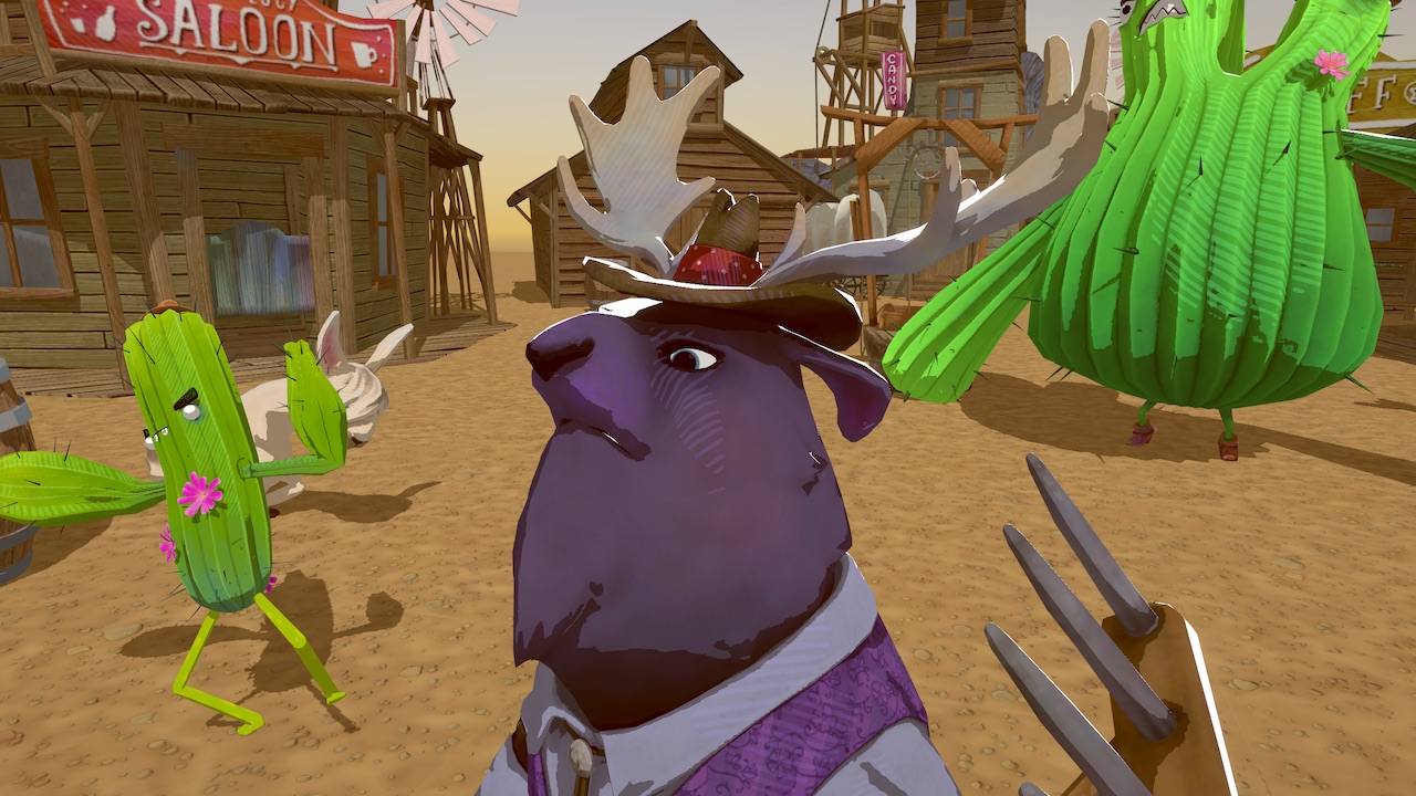
GitHub
A recreation of Zelda: Breath of the Wild's toon shader in Unity, using Shader Graph - ciro-unity/BotW-ToonShader
A different question, does anyone know why I am missing the option to rename path of my shader in shadergraph? Manual states that I should be able to rename it in Blackboard, but I cant - it just says "Shader Graphs" greyed out. https://docs.unity3d.com/Packages/com.unity.shadergraph@7.3/manual/Blackboard.html
ah nvm, i actually have to double click that - a bad UX choice there I am sure more users are struggling with.
@faint notch The alternative method in my post is basically exactly what Ciro's does, just tided up a bit.
#if !defined(_MAIN_LIGHT_SHADOWS) || defined(_RECEIVE_SHADOWS_OFF)
    ShadowAtten = 1.0;
#endif
This part doesn't do anything, as the next lines replace the ShadowAtten value anyway. I think this was just left over from copying it out of the Shadows.hlsl - where it usually does return 1.0 to escape the function early if the shadow keyword isn't defined.
I also removed the SHADOWS_SCREEN stuff because as far as I'm aware URP doesn't actually use that anymore.
It still won't account for shadow cascades + smooth shadows without altering the function more, so I prefer the hacky keyword method for now. Hoping some proper support for adding shadows to the unlit graph will happen at some point though.
Aha, I see - thanks for clearing that up!
I guess it works nice as long as you have it in a Sub graph, so it would be easier to fix/swap out if a future version would break the keywords hack.
Yeah, that's exactly how I'm using it currently
👍
Any reason why you are using World instead of Absolute World in Position space ? @regal stag
`The Absolute World option always returns the absolute world position of the object in the Scene for all Scriptable Render Pipelines. The World option returns the default world space of the selected Scriptable Render Pipeline.
The High Definition Render Pipeline uses Camera Relative as its default world space.
The Universal Render Pipeline uses Absolute World as its default world space.`
Would that potentially cause some issues on HDRP for the light calculation?
I don't think these light/shadow methods work in HDRP anyway
aha
Idk if this is the right spot to ask. But I have some grass that I want to blend with the (mesh)terrain. It does in some spots, but clearly that isn't working everywhere. What would I do so that the grass seamlessly blends with the terrain?
Any idea how to recreate this? It looks like it was raymarched
https://twitter.com/fancyzero/status/1177424902791368704

reproduce blender metaball in unity shader, by looking into the densfunc in blender src
stiffness * clamp0(1- distanceSquared/radiusSquared)^3 https://t.co/O4YSqZpmPL
I have a compute shader problem. I want to output an index of a closest point in a collection to another point. I was thinking of passing the latter point as a constant buffer and writing the closest point index into a 1 element compute buffer int. But my concern is whether a race condition is gonna mess up the result? Can several threads read and write to the buffer at the same time?
Does the compute shader not suit for such a task?
It can, but it will most likely require atomic operations or other "locks" to stop the cores from clobbering each other's writes.
I suppose you could output the distance and an ID/index into an append buffer for each ID and then scan through it and find the lowest distance's ID.
But IDK what's faster, the atomics or the append+scan.
Any idea why the normal for my grass would not be the same as the normal of my mesh when on a hill?
(I use raycast hit.normal to get the normal of the terrain at each grasses position)
(Sorry, I know it is a bit hard to see.)
It is a bit easier to see here. The where the grass doesn't match the terrain, and I have no idea how to fix it.
Do you alter the mesh? If so, in C# or in the shader?
If C#, IIRC there's a recalculate normals function you can call.
If in a shader, you'll have to compute it "manually".
@grand jolt Google metaballs unity shader.
Well i tried to google it but it's mostly raymarching (which is expensive) and marching cubes (which are hard to set up because bounding box)
Yeah, but the most common way I know of is a distance function...so it's basically ray marched.
There's some "cheats" out there using I think spheres that are morphed by vertex pos.
But I can't point you to them, sorry.
Hmm
I found something called "Normal Blending"
@meager pelican The terrain mesh is not altered. I have edited the grass mesh in blender so all it's normals are pointing up. I have custom lighting for the grass shader (ASE), I am using instancing for the grass and using Raycast to get the point for each grass, when I do that I also get the normal of the terrain at that point and set an instance property on the grass shader.
Basicly we need to blend normal vectors of polygons nearby
MW99: Put the normals into the color and see what you're getting...see if it matches up to your terrain and you're getting what you think you're getting.
Yeah, UP, IDK. I've reached my current limit on that topic. Last one I did was ray traced.
@meager pelican That was the first screenshot. The terrain and grass normal are the same when upright, but seem to diverge slightly as the terrain gets steeper.
But how does the grass mesh know about the terrain mesh normals in a shader?
Do you have a normals buffer?
There is a depth+normals option in some pipelines. I think URP doesn't have it though IIRC.
Instance vector3 property called "UpNormalVector". This is the lighting I use for the grass.
That's just a world up vector, no? (Don't do ASE).
Or are you setting that in C# per instance, is that it?
Yeah
Hmmm
It doesn't look like what I'd call a normal.
Normals are usually tangent space and look purple.
Worth researching how unity stores normals...maybe. Guessing.
I dimly remember something about offsets to the regular normal, but maybe that's only for a normal map. I'd have to play with it.
OK, per this, the normal-map is an offset to the regular surface normals.
IDK what ASE is expecting when you do what you're doing...the offset like you'd use in a normal map, or the actual surface normal.
https://docs.unity3d.com/Manual/StandardShaderMaterialParameterNormalMap.html
But see ~1/2 way down that page.
You seem to be doing an nDotL with a max 0, val. And calcing attenuation and ambient.
Which makes sense.
So IDK why your values are different when you set them in C#. How could I tell?
Precision?
This is the result of having the terrain display it's world normal, and the grass display that vector3 that is set from c#. They should be exactly the same...
Wouldn't blades of grass be pointing left or right, while the ground points up?
I thought you may be right, so I removed the rotation from the instancing, but no dice.
I think MS is right. The blade itself would be aligned with the terrain normal (ish) but the surface normal of any blade of grass would be orthogonal to that.
Just tried it with rotating them to align with the terrain normal, but that had no affect.
But...if those colors are normals, and the green terrain is "up", the grass should be pointing along the X or Z or combination thereof. So it shouldn't be green! I should have Red or Blue in it. I would think. Some combination of that. Maybe some green if the blade is on an angle relative to world "up". I would think. Envision a horizontal line as a blade surface-normal.
@meager pelican This is the result of displaying the normal on a sphere instead of on a planer surface.
Looks right, green being up (R, G, B), (X, Y, Z)
Does anyone have a shader which can be used to place alpha mapped and lightmappable decals on terrains?
Specifically, I have some roads created with River Auto Material on a terrain, but the shader they used is not really up to the task in VR because the roads float a bit off the surface of the terrain out of necessity to make them render in front of the terrain at a distance.
I feel like there must be a better way to do this though than lifting the road off the terrain, but I'm not a shader expert.
However, I was thinking... what if you could tweak the Z value of the pixel you're about to write, to cause it to be written in front of the terrain regardless of whether it's slightly behind it, so the decal can sit flush with the terrain and LOD changes in the terrain which might make it go partially behind it wouldn't affect it, but hills and such having greater z depth would still draw in front of roads in the distance.
Or... maybe a vertex shader could be used to move vertices in the path to be closer to the camera the further in the distance they are, so that nearer vertices aren't moved away from he surface, but ones further away are so as to avoid those LOD issues?
Looks right, green being up (R, G, B), (X, Y, Z)
@echo badger The surface normal of the grass blade is NOT up! It's sideways. Grass blade... It's TIP points up, it's flat blade points to the side....
So it wouldn't be green.....
Look at the side of the sphere....
@sinful shuttle You can maybe try a stencil, and draw the road first, followed by terrain that honors the stencil. IDK if you can pull that off if you're using unity terrain....but...
You can tweak the VERTEX you're about to write.
This page seems to indicate it's possible to tweak the z value of a fragment: https://docs.unity3d.com/Manual/SL-CullAndDepth.html
like you said in the vert() stage
Well, not really. Not if you're doing early-z testing, since the pixel shader is never even called if it fails the z-test. 🙂 😉
That's usually a beautiful thing. Much faster.
What part of that page says you can modify the z-value? Maybe you can, but I'd watch out for hardware variants.
But you'd have be able to tell if a tree or a fence should block the pixel.
@meager pelican I know... That is the idea... I want the grass to have the exact same normal as the terrain. That way you can't see the grass unless it is a different color
@meager pelican What part? This part:
Offset Factor, Units
Allows you specify a depth offset with two parameters. factor and units. Factor scales the maximum Z slope, with respect to X or Y of the polygon, and units scale the minimum resolvable depth buffer value. This allows you to force one polygon to be drawn on top of another although they are actually in the same position. For example Offset 0, -1 pulls the polygon closer to the camera
ignoring the polygon’s slope, whereas Offset -1, -1 will pull the polygon even closer when looking at a grazing angle.
That looks like a vert mod though so it's for the whole polygon, not per pixel.
Well, it's ALL pixels.
I need some help. For some reason, my material is showing correctly when I view the prefab of the object but it is different in the scene:
@echo badger Why don't you just clip the pixel? Can you selectively tell? Or does it need to obstruct?
And when it's a different color, how do you want light to affect it? Because then you get into your NdotL stuff.
With the real normal.
@meager pelican This is sort of the result I am trying to get.
You can really see the difference between the grass and the terrain.
i cant figure out why it is telling me this and i cant get my character to touch the ground
How would I implement this:
"The simplest solution would be to add a small value to the clip space z in the vertex shader. Basically:
o.pos = UnityObjectToClipPos(v.vertex);
o.pos.z += 0.001;"
https://forum.unity.com/threads/different-z-offset-per-triangle.499280/
Unity Forum
Name says it all. I'd like to use Z offset to fix some Z flickering issues. I know you can do this with a shader using Offset;...
Into this?
I know next to nothing about shaders, so I don't know what v.vertex is, if its available to me, if o.pos is pre-exisiting or has to be declared, and if it's different from the object named o in that shader code and they just happened to pick the same name, or what. I need to move the vertices of a path towards the camera and setting Offset doesn't seem to be doing the job without ridiculously large numbers for the offset which breaks other things, and from what I've read that's driver specific in the way it functions so I can't be sure it will work reliably on different cards anyway, so I'd like to just try tweaking the vertex positions manually.
@sinful shuttle So you're having issues with Z fighting?
@low lichen Yes. The script I'm using to generate paths on my terrain solves Z fighting by offsetting the path from the terrain vertically by -0.1 on the Y axis, which looks fine in a flat game, but in VR with depth perception, it's quite obvious.
You can see on the left side of the rock there how it clips through it.
@echo badger I'm not sure I'd approach that by making the normal of the grass be the same as the normal of the terrain.
It's hard to say. Looks like a toon shader variant to me, maybe with blending of grass? But regardless, I have the grass normals be "normal" excuse the pun.
It's almost like it's unlit, but shadowed and colored.
Why is the grass lighter in the center? Look at the left and right edges, it's less saturated green. So is that due to some lighting/normal calc, or is that just the coloring? Do you think that's a screen-space effect/decision, or the natural color variation on the terrain, or what?
If I remove the offset from the path, it no longer clips through the rock, but you can see it clipping down at the bottom of the screen now. And it gets much worse elsewhere, especially when looking straight down.
And that was with Offset -4, -4, in the shader. With the default of -2, -2, it looks like this with the path flush on the ground:
When using Offset, the first -4 adjusts based on how much the polygon is angled away from the camera, and the second is supposed to just tweak the z towards he camera in general, but I've found the second number has to be like -100000 or more to have any noticeable effect, and with it that high the rocks draw behind the path. And Offset is not documented well apparently and its up to the card makers to define how it functions so putting in numbers that large would seem like a good way to get vastly different results on AMD vs NVIDIA. That is if it even worked well, which it doesn't. So the vertex Z tweaking I'm trying to do now is my last resort to get a consistent result I can control and maybe make function how I need it to.
More info on Offset is here: https://forum.unity.com/threads/offset-parameters.23281/
Unity Forum
The docs say:
Offset Factor, Units
But I can't figure out what this means. I presume factor is a multiplier for the units, but in what direction?...
I'd avoid offset keyword like the plague, and just offset z in the vert shader if that's what you want.
Vert() outputs clips space anyway, so you can just offset it. As I'm sure you know. 🙂
But like we discussed above, that's per poloygon, not per pixel (it will offset all pixels)
You could change the shaders of both the terrain and the path to ensure the path is always in front of the terrain. That can be done using the stencil buffer. Have the terrain drawn first and write some value to the stencil buffer. Then draw the path with ZTest Always, but only draws where the stencil value is the same as what the terrain wrote.
That's assuming the terrain can never occlude the path, which is definitely the case if the terrain is just a heightmap
Hey guys, i have a problem with Unity Ads, when i am in the Editor, the test ads appear, but when i test the game trough Google Play there are no ads
@ me if you think that you can help me. Thanks
@meager pelican "I'd avoid offset keyword like the plague, and just offset z in the vert shader if that's what you want."
I'd like to to that, but I don't know how. I have almost no experience working with shaders.
@low lichen "That's assuming the terrain can never occlude the path, which is definitely the case if the terrain is just a heightmap"
How do you come to that conclusion? If I have just one hill in the middle of my terrain and the path goes around behind it, the path should be occluded by the terrain.
That's true, didn't think of that scenario
I'd like to to that, but I don't know how. I have almost no experience working with shaders.
@sinful shuttle
You'd have to pastebin your current shader, then we can help you with the z-offset part. Not guaranteeing it will work, mind you, but we can try it.
For future reference: https://answers.unity.com/questions/1443941/shaders-what-is-clip-space.html
Unity is the ultimate game development platform. Use Unity to build high-quality 3D and 2D games, deploy them across mobile, desktop, VR/AR, consoles or the Web, and connect with loyal and enthusiastic players and customers.
@meager pelican https://pastebin.com/40X8z8GR
Pastebin
Pastebin.com is the number one paste tool since 2002. Pastebin is a website where you can store text online for a set period of time.
There's some code in there at the start surrounded by comments that someone else offered up. It doesn't work yet though, I think it requires some vertex data to be passed to the shader and I was currently figuring out how to do that.
OK, I'm not going to figure all that out, but we don't have to do that anyway.
We need a vertex function though, since that's a surface shader.
Line 54 currently says this:
#pragma surface surf Standard keepalpha decal:blend
We need to tell it to use our custom vertex function.
#pragma surface surf Standard keepalpha decal:blend vertex:vert
and then we need to add some custom vertex stuff. We just need the "overrides" as there's an internal default vert() function that surface shaders use before calling our custom function.
void vert (inout appdata_full v) {
          v.vertex.z -= .01;
}```
That should be close, but it might balk at the appdata_full struct. IDK yet.See what errors you get, if any.
We'll probably make the offset a property of this works.
@meager pelican Well it compiles, but it doesn't seem to work as expected. the more increase v.vertex.z -= .01; the more the road texture shifts to one side, and it has no effect on reducing clipped regions.
Crap. It's calling it at the wrong time!
It's calling it before transformation to clip space.
Try putting that custom code into the vert() instead if the line I gave you.
I should have guessed that it would do that, as you can deform mesh verts using a vert() function in a surface shader.
You could always edit the code manually, but I don't want to suggest that, instead try the custom code, that might be what it's doing...figuring out the camera vector and moving it along that.
My bad. But you still need a vert() function.
So we're 1/2 way there.
And it looks like that custom code is doing what you'll want.
void vert (inout appdata_full v) {
 appdata_full o;

 float zoffset = -1.0; // v.color.r;
 o.vertex = UnityObjectToClipPos(v.vertex);
 float3 cameravec = normalize(mul(unity_WorldToObject, float4 (_WorldSpaceCameraPos, 1.0)).xyz - v.vertex.xyz);
 float4 desiredpos = UnityObjectToClipPos(v.vertex + zoffset * float4(cameravec.xyz, 0.0));
 v.vertex.z = desiredpos.z * o.vertex.w / desiredpos.w;
}
Why does Discord keep deleing my posts if I don't remove the tabs on the left side of the code?
Hey guys. I see Amplify bundle is on sale. Is it worth getting or does Shader Graph do mostly the same stuff?
Anyway, I tried that code above but the road just disappears.
You need to put code into ` (3 of them in a row) and then close with 3.
It might work if you put that custom code into the Surf() function.
What happened when you tried that (you said it wasn't working yet)?
does any of you guys know how to make a simple object terrain blend shader?
@meager pelican float zoffset = -1.0; // v.color.r; o.vertex = UnityObjectToClipPos(v.vertex); float3 cameravec = normalize(mul(unity_WorldToObject, float4 (_WorldSpaceCameraPos, 1.0)).xyz - v.vertex.xyz); float4 desiredpos = UnityObjectToClipPos(v.vertex + zoffset * float4(cameravec.xyz, 0.0)); v.vertex.z = desiredpos.z * o.vertex.w / desiredpos.w;
So I added that to the end of surf(), but it says invalid subscript vertex on the second line there.
When I said the code wasn't working yet in the pastebin, that's because the original code with o.pos instead of o.vertex didn't work in surf either and also threw errors and I realized the author had said to put it in the vertex function but I didn't have one, so I was trying to figure out how to add one.
Yeah, I think we were closer with the vert() funciton.
What he's doing is moving it along a vector from it to the camera, and then adjusting for perspective, if I read it correctly.
But I'm not sure why the road vanished. What was zoffset set to?
I tried it with v.color.r, 1.0 and -1.0. None made any difference.
It's really hard to do this without playing with it