#archived-shaders
1 messages · Page 170 of 1
You can get full 32 bit floats with https://docs.unity3d.com/ScriptReference/RenderTextureFormat.ARGBFloat.html
but you may not need it, depending on what you're doing.
Then you can use 8, or 16 or 32 bits per channel with something like ARGB32 or ARGBHalf or ARGBFloat

Yeah, URP knows about unity texture formats AFAIK.
That's what I pass. Not the R8G8....
Alright, thanks.
And for custom post processing, it makes the most sense to keep using the camera descriptor itself because it's the source and also the destination of the pass, right.
IDK, I'd have to research, but sounds logical.
I haven't messed with custom post processing much in URP.
I know you, Beat, you'll find a tut or something and nail it.
I have everything working already, I'm just wondering what a real graphics programmer would say 😄
@grand jolt since you're doing post processing
be aware that CommandBuffer.Blit doesn't copy over the depth/stencil buffer
I found that out today
Oh yeah, I don't think I managed to make stencil work in postprocessing yet.
I think I'm doing similar things right now as you
using GraphicsFormat.R8G8B8A8_SNorm right now but no idea if that's any good, need to look into it more
How can I make A moving diagonal line? I want tho achieve kind of blink effect that moves across whole mesh once in a while
this doesnt kinda work as I expect 😦 It repeats itself and its to fast. I want a kind of shine blink
So how to scroll a UV once per X seconds?
@frozen mason Does it need to move back and forth in the sine movement? Perhaps something like this :
ACtually I would like it to go always one direction
Okay nvm @regal stag it can go in sine
This blink effect is what Im after for
Lot of effects going on but I think I see which part you are referring to. I don't know if they are using a diagonal gradient like this for that - it's probably just horizontal/vertical and going along specific uvs. It'll give a similar effect though
Yeah ur graph gives something similar that 1st one going to check the second one
Yeah, the second one is a repeating pattern going in the same direction. You might want to "zoom in" a bit for the flashing effect, which could be achieved by a Multiply/Divide node after adding the XY/RG from the uvs (but before adding the time).
Sweet got it! Just a little bit of tweaking needed. Goddam I rly owe you a beer. And if I ever release demo/game for sure you will be in the credits ❤️
LOVE IT ! @regal stag Thanks
Is there some kind of order determinism for Graphics.Blit method?
How could I apply a gradient around a sphere? I have no idea how to do the UV, with shader graph
Ok nvm I found a way
Is there some kind of order determinism for Graphics.Blit method?
@crystal light
Are you asking how the engine queues that up? You can do the blit in a command buffer if you want. And also for SRP, there's a callback that you use and wrap the blit in that callback function if you're doing it for post processing.
https://docs.unity3d.com/ScriptReference/Graphics.Blit.html
Otherwise I suppose from our perspective it "just happens" if you call it directly, internally I think it's added to the renderer's queue at that point but I'm unsure.
You can use the various "OnWhatever" functions to call blit too.
@grand jolt See above, there's a callback function for https://docs.unity3d.com/ScriptReference/Rendering.RenderPipelineManager-endFrameRendering.html
(Regarding your post processing question). That's for the FRAME not the camera. If it helps you any. See the Graphics.Blit doco. But again, I'm still not versed enough in SRP to know how to best do it per your question. All depends I guess.
I wasn't asking how to do post processing 🤔 It's done using scriptable render features and I've written enough of them at this point.
I was asking about texture descriptor for post processing textures.
Which I pass when creating them.
And for custom post processing, it makes the most sense to keep using the camera descriptor itself because it's the source and also the destination of the pass, right.
@grand jolt
^^ this one. 😉
Ah.
Like this: cs public override void Configure(CommandBuffer cmd, RenderTextureDescriptor cameraTextureDescriptor) { var fullScreenDescriptor = cameraTextureDescriptor; fullScreenDescriptor.depthBufferBits = 0; fullScreenDescriptor.colorFormat = RenderTextureFormat.ARGB32; cmd.GetTemporaryRT(GrainProperties._SketchGrainMap, fullScreenDescriptor); }
so huh
the post processing stack V2 makes the screen grey in VR for me
like, flat grey, turning off post processing fixes it but you know, I can't use PP then
layer setting, volume setting doesn't really matter since the screen's grey regardless of if there's a volume or not
Yeah @grand jolt , you can use the descriptor (which is just a convenient way to store a bunch of settings) or just call it the "hard" way and supply all the values). It's going to do the same thing either way, basically.
Again, that wasn't the nature of the q 😄 It was basically: should I convert values arriving from the camera to a different format or nah.
It's more of a philosophical q, what would a graphics programmer say.
I can't tell you what's best for what you're doing, since IDK what you're doing, nor what I'm doing 1/2 the time.
😉
I'm a "newb", dude. But I'm having tons of fun.
It's all hardware dependent anyway.
Are you ready to describe what you're using it for? I know...noise...but that's actually vague. How many channels, what level of float precision do you REQUIRE? That should tell you. Then you have to decide on platform differences, if any.
Generally, the fewer bytes you have to trudge through the better, for throughput.
The GPU hardware will still have memory cache of some type (this varies, tile based works differently than say desktop) and a memory bus, and you have to shove a lot of data through all that many times per pixel. As I understand it, so smaller = faster = better, but your needs are your needs. Some platforms may "like" certain formats better than others, but the pros here can tell you what's pretty standard and universal.
And that bus is WIDE on desktops, which is partly why they just use floats for everything I think.
After changing from built in to urp what should I do with the height map?
@pastel cape The short answer is nothing. The URP lit shaders don't have any height/parallax mapping like the Standard one does.
If you really want it though, you could recreate the lit shader via shadergraph and add it in. I believe it would be using something like this for the UVs into all the texture samples (except the heightmap itself) : https://forum.unity.com/threads/how-do-i-use-a-heightmap-in-shader-graph.538170/#post-4164853
(There was actually some recent changes to the URP lit shader on github, and it does actually include height/parallax mapping now, but that version is not available in any URP packages yet)
Thanks btw when I was using built in render pipeline .when I drag a texture on a model it was creating a material with the texture as base map. Now in urp when I drag the texture it creates simple white grey material with the texture not attached as a base map any solution for this? @regal stag
@pastel cape Probably don't drag textures. Set up materials before hand and drag the materials onto objects instead.
Bruh it's easy to say unless you have 3.5k textures😂
Might be able to write an editor script/extension to create the materials and assign the textures for you
Any tutorial?
The example on this page is probably a good starting point :
https://docs.unity3d.com/ScriptReference/AssetDatabase.CreateAsset.html
Also would need do use material.SetTexture("_BaseMap", texture); to set the texture. How you obtain the texture references though Idk
Maybe the #💻┃code-beginner or #↕️┃editor-extensions chat could help further.
@cyan I am actually datamining a level from critical ops (a mobile game) for cinematics. don't worry I asked the moderators of c-ops community
That's not really what I meant by "how you obtain the texture references though idk". Where you are getting them from isn't important (as long as you have permission). I meant more about how you load those textures from within unity to attach them to the materials. Maybe something like AssetDatabase.LoadAllAssetsAtPath to create an array, then loop through it. I don't know if that's the best method though. https://docs.unity3d.com/ScriptReference/AssetDatabase.LoadAllAssetsAtPath.html
(edit : actually that probably won't even work anyway. It seems it doesn't load assets from a folder but only "sub-assets" that can be included within other asset files (like fbx which can contain multiple models/materials/etc). What a misleading function name. Probably need to rely on IO.Directory.GetFiles & LoadAssetAtPath instead).
@empty oar bro i can't say how mush you helped me thx a lot dude. I will continue this work tomorrow gn ❤
@empty oar bro i can't say how mush you helped me thx a lot dude. I will continue this work tomorrow gn ❤
I was wondering is there a way to know what pixels a light brightens up the screen?
In a shader ? Well, when you do your own lighting calculation, obviously you know it 🙂
Uhhh ok instead I am just gonna ask this. Is there a way to know if a specific light hit an object?
(Also thx for responding to the previous question. I just switched question cause the anwser for this question Is better than the anwser to the previous question)
There isn't an easy AND precise way to do this.
But you could aproximate with raycasts if the objects in the scene have coliders.
Else it involves solutions like rendering from the point of view of the light and check the pixels of the texture to see if the object is visible.
Could I try to assign a collider with IsTrigger to the pixels that the light affected?
You can't assign colliders to pixels, only to objects
Umm ok then just to clarify when you said There isn't an easy AND precise way to do this. did you mean There is a precise way to do it but it isnt easy.?
Wait a sec
Couldnt I basically take a part of the script from untiy that makes the light then basically use that part to calculate where the light will hit
and if the player is in there then he is in the light
Yes, that's what I meant to say, there is a (some) precise way, but not so easy.
Also, this conversation is not really shader related, we should maybe switch to #💻┃code-beginner .
Define "the part of the script from unity that makes the light"
I was wondering with the 2D Point Light how do you get the yellow circle with the arrow to point the light, around the light
If you mean to rotate it, I think you rotate it like any other gameobject, with the rotation tool.
I'm still not sure what you mean by to point the light, around the light. Those yellows gizmos are basically just to control the point light's "angle" and falloff I think.
Currently it's the full 360deg, but that can be changed so it's a bit more like a spotlight
Oh it looks like you can drag the semi-circle bit at the top around too

We have a new 2D Renderer for 2D games, which includes the features 2D Lights and 2D Shadows! In this video, we're going to take a look at how we can use Unity 2019 and the Universal Render Pipeline (URP) to add 2D Lights and Shadows to our 2D games!
Download the Lost Crypt p...
Wait so how do I get the yellow gizmos?
I'm confused, are you trying to use the 2D lights or replicate the gizmos for them? I think the yellow gizmos should just appear when one of URP's 2D lights is selected, as shown in the video above. If you can't see them they might be hidden/disabled? Maybe check the gizmos button in the top right corner of the scene view.
I think I cant see the yellow gizoms because of this error```The serializedObject should not be used inside OnSceneGUI or OnPreviewGUI. Use the target property directly instead.
UnityEngine.GUIUtility:ProcessEvent (int,intptr,bool&)
That might be related, maybe try updating URP version
Its on the latest version and that error only pops up when I press the point light object
Which version is "latest version"? You might also need to update Unity itself to get newer URP package versions. I'm on 2020.1.2f1 and URP 8.2.0 and the 2D lights are working fine for me.
If it's not listed in the package manager as an update, you need to switch unity version. I think that's a beta version too right? Probably a good idea to be on something more stable - it's possible the bug is with that unity version and not URP anyway.
I removed the package and reinstalled it and its good now
wondering if anyone has any idea where to start on a shader idea I need for a current project. I want it so that when a certain invisible object is iluminated by a specific light source, it'll reveal whatever parts of the object affected by said light source.
I don't really have much knowledge of shaders and I only really want to learn enough to make this idea come to fruition so any relevant tutorials would be much appreciated
So a "magic lantern/light" that "reveals" an object?
What pipeline?
@south hemlock
P.S.
Does it have to be a "real" light?
Is the light from the camera facing outward, or anywhere? (3D right?)
So a "magic lantern/light" that "reveals" an object?
yes
im not sure what you mean by real light but the idea is that the light that creates the effect would be both produced by the player (think first person flashlight sorta deal) and by a special object
I haven't setup my pipeline yet as the packages for them are missing from my package manager so whichever would be easiest and preferably compatible with shader graphs
@meager pelican
And it's 3D not 2D, right?
OK, so if you want SG, you'll want either URP or HDRP. Go with URP if in doubt unless you want real fancy visual and limited to higher-end hardware.
What about shadows?
If some object is between the player-with-flashlight and the revealed-object, does that thing cast a shadow from the flashlight making that part not-revealed?
If so, it's a bit more complicated. Otherwise you can just "tell" if a pixel for the object is in the 'cone' of the flashlight, and do that in a pixel shader.
BUT.
If you want shadow casting and special reveals, like with a "real" light, then you'll have to do something else.
its 3d yeah
im not sure I understand your example
@meager pelican
are you asking if say the invisible object is currently revealed and some normal object casts a shadow on the revealed invisible one if that would hide the part of the object touched by the shadow?
Right, that shadow would be cast from the flashlight or whatever "magic light".
Due to occlusion by some other object.
Otherwise, you can "just" pass the code's vector and size to the shader and let the pixel shader decide if it is intersecting the cone.
But if you want "real" light calcs, you need to know about shadows, and shadow maps and stuff and it gets more complicated.
so in the first method would that mean the cone could go through walls and what not?
beacuse otherwise im not sure I get what the meaningful difference of the two are
OK, conceptually yes, but that doesn't mean you'd have to reveal the object if it's on the other side of the wall. What it means is that if it's (1) You, (2) a chair, (3) a Ghost and the ghost is revealed by the light, and the cone of the light is 1/2 cut off by the back of the chair, what do you see? The top 1/2 of the ghost, or the whole ghost? See?
The idea was to make it so the object is only partially revealed based on what parts are being hit by the light
Including the light being occluded by other objects. Yeah, "real" light calcs then.
Shadow maps! And maybe a stencil. But IDK that you can do that directly in shader graph, you're asking for something that takes some code editing, unless someone else has a better idea. Maybe a stencil and another pass. IDK.
Thinking.
What a shadow map is, is a depth map rendered from the light's point of view. So even if you throw the flashlight across the room and it lands illuminating the object, it would still work.
I can manage code editing although I am a pretty fresh beginner so I wanted to see if maybe shadow graphs would work for this
ohhh cool okay
SG will give you auto lighting. But it won't do this special effect, exactly.
do you need a render pipeline for shadow maps?
All of them do some kind of shadows.
I'm still thinking. Trying to isolate it. I was thinking about a camera that only had that one light active, and all the objects for shadows still. But that's a lot of rendering maybe, depending on your scene.
the game would be largely in the dark but I wanted the maps geometry to still be visible when the object is infront of it and not revealed
which is why a normal light wouldn't work
Well, I'm talking out of my guesswork posterior here, but I'm thinking:
The shadow map for that light would tell you how far the light got before it was occluded. And if your "special" object is nearer than that, then that pixel is "lit" otherwise it isn't.
Is what I'm thinking.
I think that would work yeah
would that be terribly complicated for someone who is new to shaders to learn to make?
So you'd draw this special object in another layer, but be aware of that light's shadow map.
Taint easy. But probably doable.
Maybe someone smarter than me will have a better idea here.
so id just need to learn about shadow maps then?
Yeah, or give it a day and see what someone else says. Also maybe check into spotlights.
Yeah, np.
I mean, someone might pop in and say "Hey Carpe you schmuck, you didn't think about __" and have a better idea.
Some further reading.
https://medium.com/@shahriyarshahrabi/custom-shadow-mapping-in-unity-c42a81e1bbf8
https://catlikecoding.com/unity/tutorials/rendering/part-7/
Also note that Shader Graph generates code, and you can edit it from there (but you have to keep it text after that). So a lit graph would generate lighting for you, then you can customize it.
See links in article too.
Will probably make your head hurt if you're new to shaders, but don't be intimidated.
@south hemlock
Medium
I am going to walk through how to sample your own shadows from the standard shadow mapping pipeline in Unity. My application is for…
A Unity Rendering tutorial about supporting shadows. Part 7 of 20.
Alright got it, thanks!
So if there's a part of my object behind the rendered face, my transparent shader renders it too, even if the alpha is 1. How do I fix this?
Hi any way to make a shader that overlaps shades and react to light, similar to sprite diffuse shader? Im using build in render pipeline on a 2d top down game and having this problem with the shades of my trees:
Im using this shader but then my character always appears at the back of the shade and the shadow should be transparent
Hey guys! I'm using the Tiling and offset node, to offset a sprite in 4 directions, to cause an outline of the object. But this makes the outline bigger, the bigger the sprite is. Is there a way to have this a fixed width?
I think it's a standard way of doing this.
@west fulcrum You'd need to control the strength/thickness of the offset in each direction by the scale of the sprite (probably using divide since scaling should reduce the thickness not increase it even further).
There's a Scale output from the Object node.. but I don't know if it'll work with sprites as I think their batching doesn't allow for per-object info like that. Maybe sending a Vector2 scale property in instead would work? But that would probably mean different material instances so wouldn't batch anyway?
Oh unless the size of the sprite is to do with the texture and not the gameobject, maybe you can use the texture width/height from the ... uh ... texel size node?
@regal stag thanks! The scale is 1 on both, but i guess a script could send in the sprite width as a factor somehow? Yeah they dont batch i guess since only one object can glow at a time
Yeah i looked at the texel node but i’m not sure if it would work, i have to test it. Not sure if it differs if i use a single sprite png or a sprite from an atlas/sprite sheet
Ah yeah, that might be a problem too. I guess you could also create separate materials with manual widths for varying object sizes. Like a "small", "medium" and "large" version or something.
anyone got any suggestions on how to draw a solid arc inside of a compute shader off the top of their head
Hello I have two questions about ray tracing in Unity,
- How does ray tracing works in Unity? How good is works? Is it really worth it?
- Is there a way to make my game support "RTX ON RTX OFF" that you can just press a key and the game (if some reloading needed it's fine) will switch ON and OFF from using Ray Tracing
Is there a shader expert i can pay to solve a problem that has been bugging me for years...?
feel stupid for even having to ask this but should I not be seeing 4 triangles in this preview?
The Tiling in the Tiling And Offset node doesn't actually make the uvs "tile". It just scales/resizes them as textures will tile with the repeat wrap mode anyway. For procedural shapes like the Polygon node you'd need it actually tiling, which can be produced by using a Fraction node in between.
Ah I see thanks for the explanation
Would it be possible to randomise the offset for each fraction?
Like scatter
Hmm, maybe a little but if you offset it outside of the square the triangle is just going to be cut off.
So there is no way to randomly scatter an image without distorting it in some way?
Would be a shame since the whole style I'm aiming for would require that
It's probably a bit awkward to do it in shadergraph. You could maybe loop creating each polygon separately but that would need to be in a custom function node, and probably isn't great for performance. It would be better just inputting a texture with already repeating triangles.
Hello there, does this feature actually work?
I can't find where to define de material quality level in the RP settings
@peak pawn Might be interested in something like the method described in the answers here : https://blender.stackexchange.com/questions/102692/randomly-populating-procedural-shape-or-image-texture-in-cycles
It's for blender but would be a similar concept, though may not be easy to replicate. Performance might be okay if there isn't many layers, but idk.
Does anyone know if it's possible in Shader Graph to crop based on a greyscale value or like project something to an ellipse shape?
this si what I have rn
I want it to take up the full circle
@mortal sage It might be related to the "shader quality" setting that is going to be added : https://portal.productboard.com/8ufdwj59ehtmsvxenjumxo82/c/134-shader-quality-settings
Don't think it's in any URP versions atm though.
Does seem a bit silly to have the keyword there if you can't change it atm though. Guess you could always create your own keyword to handle it.
I see. Would have been perfect in my case but yes, if it doesn't work yet I will use my own keyword. @regal stag thanks!
Quick question, is there any quick fix besides restarting my pc if my shader renders fine on one material, but for some reason bugs around on another material although they have the same texture and settings?
Like, before I restarted Unity it would behave very weird on the other material despite there not being a real reason to and after restart it refuses to draw at all >.>
And I am pretty sure it has nothing to do with the shader or the property settings, I tripple checked if it really is the correct shader on the material (it is) and changing the shader code only changes the appearance on one of the materials, not both.
This is strange and frustrating.
Yesterday, when I set the shader up it worked fine on both materials, only after starting Unity today it broke without me changing anything.
Holy fuck, this is revolutionary. Unity remembered that you can write tutorials for shaders https://docs.unity3d.com/Packages/com.unity.render-pipelines.universal@10.0/manual/writing-custom-shaders-urp.html
i mostly copied a shader from a brackeys tutorial (with the shader graph) and now i get this built error
on that line of the shader is just this
@dreamy hazel
right click on the master node and click 'show generated code'
that should give a different code I think?
Hm, kinda makes sense that it errors as it looks like the VaryingsMeshToPS struct doesn't include a cullFace? Seems only the Packed one does. https://github.com/Unity-Technologies/Graphics/blob/master/com.unity.render-pipelines.high-definition/Runtime/RenderPipeline/ShaderPass/VaryingMesh.hlsl
Unless this is in URP not HDRP, but I couldn't find anything else searching the github. I guess it could also be defining it's own structs rather than using those ones, idk. I'd assume it's a bug (related to two sided / is front face node?). There's probably not much you can do to fix it. Maybe try updating?
What's the point of LOAD_TEXTURE2D_X?
(Unrelated to the convo up top)
Hell, what even is TEXTURE2D_X, what is the point.
Seems like it's related to VR, https://forum.unity.com/threads/hdrp-post-processing-shaders-accessing-gbuffers.726158/#post-4846304
I see. Cause I've even dug down to platform define headers and couldn't figure it out.
Big thanks.
What's the load for tho?
I'd assume that's the same difference between Texture.Load and Texture.Sample. https://docs.microsoft.com/en-us/windows/win32/direct3dhlsl/dx-graphics-hlsl-to-load
I think it might use pixel positions rather than uv coords?
I really don't know though, I've never really used it and the docs here aren't exactly clear
I see, thanks again.
Aaaand blitting to camera target doesn't work anymore on URP 10 unless I put the pass as After Rendering Post Processing.
I'm working with stencils but it only seems to work when I have MSAA enabled in the render pipeline on URP?
right is game view
and so when I disabled MSAA, the game view doesn't take into account the stencil mask
but in scene view it always looks right
I do see that when MSAA is disabled, _CameraColorTarget uses R8G8B8A8_SNorm
and when MSAA is enabled, it uses B10G11R11_UFloatPack32
Does R8G8B8A8_SNorm not support stencils somehow?
Cyan I found on the forum you and Beans had some experiences with stencils + msaa
I'm trying something very basic, in 1 pass I write several objects to the camera buffer using this shader
then in another one I check Ref 1 and draw a purple color when it's not equal
Also weirdly enough, when I DISABLE depth texture, the stencils work when I have MSAA disabled
I'd assume that the format of the color texture isn't too important. Stencil is usually related to the depth. https://docs.unity3d.com/ScriptReference/RenderTextureDescriptor.html suggests there is a stencilFormat, and that only R8_UInt is supported for that, which is probably the default anyway. The descriptor would also need to specify 24/32 bits for the depthBufferBits part. Seems strange that those wouldn't already be set though.
Out of curiosity, is the Post Processing option on the camera enabled? I know I've had issues with the depth texture not rendering correctly without that or MSAA enabled.
post processing enabled or disabled doesn't give me a difference I think
How are you applying the stencils? Is it just gameojects / mesh renderers or something different?
I have a stencil pass like this
it uses context.DrawRenderers to draw objects with a 'stencil mask shader'
the stencil mask shader has an empty frag function
just basically does this
Hmm okay. I think this is probably a bit outside of my knowledge 😛
maybe I'm doing something wrong after
I'm going to give that link you sent a read
thanks
If anybody knows more about this, feel free to tag me 🙂
@devout quarry It might be a good idea to check if using mesh renderers in the scene still work with the stencils or not. Or possibly with the RenderObjects feature + stencil overrides too. Just wondering if it's maybe a bug in URP rather than the way they are being drawn? I kinda doubt it, but might be worth checking just in case.
I'm looking at the ForwardRenderer and they seem to be doing a bunch of stuff based on whether depth texture is enabled or msaa is enabled
they are very much linked
just need to figure out how exactly
The issue arises when the ForwardRenderer decides to do a 'copy depth' pass
Are you using a command buffer for the blit?
Did you set the render textures first?
See here (and the bottom comment)
https://issuetracker.unity3d.com/issues/commandbuffer-dot-blit-does-not-produce-the-same-result-as-graphics-dot-blit
Reproduction steps: 1. Open the project 2. Open the "Test_CommandBufferBlit" scene 3. Play the scene and notice the gray screen 4. O...
@devout quarry
Or maybe you CAN blit it to save it off, and then set it.
IDK when this happens....(copy depth pass via forward renderer).
Where does it appear in the frame debugger, and why?
Also see post #12 and #13 here:
https://forum.unity.com/threads/commandbuffer-blit-isnt-stencil-buffer-friendly.432776/
that's old though, but interesting.

Unity Forum
EDIT: I'm consolidating this thread to keep it short and simple.
THE ISSUE:
Creating a black and white image of a stencil buffer, for later use in a...
does anyone know how to create a transition in the alpha of the material better than using a threshold?
@meager pelican but if I blit from a source buffer to a target buffer
And the shader I use for that has Ref 1 Comp NotEqual or something
It will check the stencil buffer from the target right?
Not from the source
So what I'm doing is first, I render objects to the camera buffer using a stencil mask shader so that those parts of the buffer have a ref value of 1. Then, I change my target buffer to a custom render texture where I render those objects from before with a bright red color, then I blit from that render texture to the camera color again, using a stencil ref 1, this seems to work but not when Unity decides to do a copy depth pass. But maybe I'm misunderstanding and when I blit from my render texture to the camera color target, if I use a stencil in my shader it will not check the stencil buffer from the blit Target?
hey so i've been looking for a cel shader for a long time and just found one, and it worked fine, but as soon as i assigned the material with the shader on it, the shader turned the material pink. help? this is the shader btw https://github.com/daniel-ilett/cel-shading/blob/master/Assets/Shaders/FinalCelShaded.shader and im using URP if that matters

GitHub
A collection of shaders used to demonstrate cel-shading in Unity. - daniel-ilett/cel-shading
That shader isn't going to work in URP. It uses the surface function, which is only available in the built-in pipeline.
hm, so how do i make it work in URP?
Converting that specific shader to URP isn't that easy. I'd recommend searching around for toon shader tutorials using shader graph. There's probably quite a few. Unity even has one here that goes through obtaining light info : https://blogs.unity3d.com/2019/07/31/custom-lighting-in-shader-graph-expanding-your-graphs-in-2019/

Unity Technologies Blog
With the release of Unity Editor 2019.1, the Shader Graph package officially came out of preview! Now, in 2019.2, we’re bringing even more features and functionality to Shader Graph. What’s Changed in 2019? Custom Function and Sub Graph Upgrades To maintain custom code inside...
i'll try
so i should delete the shader and try do it in shader graph?
that's gonna be kinda hard, but it's doable i think
Converting the shader would likely be much harder, so yeah
I'm guessing it's gonna be either an unlit shader or pbr shader, right
If you want some other toon shader examples :
https://danielilett.com/2020-03-21-tut5-urp-cel-shading/
https://alexanderameye.github.io/simple-toon.html
https://www.youtube.com/watch?v=g8eBXCgWwrk
oh it says right there in the post
oo i remember using alexander's one but it didn't work correctly for me
Since it's doing the lighting calculations you likely want unlit, as PBR will handle it's own lighting. That said, you can't receive shadows properly with the unlit one. Some people use the PBR one but with the emission output and leave the albedo as black and 0 smoothness to allow that to happen. (It doesn't matter which graph you create though, you can swap the master node out at any time)
Personally I don't like relying on that, and instead change how the custom lighting functions work to bypass the keywords needed for shadow receiving. Somewhat similar to the main light one here : https://github.com/ciro-unity/BotW-ToonShader/blob/master/Assets/Shaders/CustomLighting.hlsl
aight
Does anyone know of any shaders that can have an object receive a shadow, but otherwise be invisible?
For which pipeline?
2017 standard
Hmm maybe this? https://github.com/keijiro/ShadowDrawer
GitHub
Shadow matte shader for Unity. Contribute to keijiro/ShadowDrawer development by creating an account on GitHub.
thanks, but it says Forward
I'm using Deferred
hm actually
it's just for a menu like part of the game, maybe I'll switch for that camera and give it a shot
not sure what's going wrong with it. Starts off mostly black/opaque
Hey anyone knows how to change to transparency of the material using a black and white texture where black means transparent?
Hey anyone knows how to change to transparency of the material using a black and white texture where black means transparent?
You'd sample the texture and use it as the alpha output of the shader. Would also need to be in the Transparent queue / surface mode if we are referring to shader graph and have appropriate alpha blending.
Hmm but how
I am new to shader graph
Basically I am new to shader
Any beginning startpoint?
Sample the texture with the Sample Texture 2D node. If it's black & white we can just take the R output and it into the Alpha input on whichever Master node you are using. Then click the small cog on the Master node, and switch it to use Transparent surface mode and Alpha blending.
Got it
Dude how you know this pls give me a beginning tutorial kinda stuff from where I can also learn some thing
I'm not really aware of any super-beginner tutorials. Maybe these will help, just found them with a quick google search.
https://learn.unity.com/tutorial/introduction-to-shader-graph
https://www.raywenderlich.com/3744978-shader-graph-in-unity-for-beginners
I have some of my own shader graph breakdowns here too, but they are more about specific effects rather than basics. Might still help if you try recreating some of them though. (I think I might already have linked it to you? Maybe that was someone else?) : https://cyangamedev.wordpress.com/contents/
Nah
@regal stag ok np
@safe gate I've tried doing that tutorial/approach and it kinda sucks since you need to write most of your shading and color calculation in a HLSL include anyway. At this point it's better to drop the half working Shader Graph and duplicate the Lit shader like here https://github.com/ColinLeung-NiloCat/UnityURPToonLitShaderExample

GitHub
A very simple toon lit shader example, for you to learn writing custom lit shader in Unity URP - ColinLeung-NiloCat/UnityURPToonLitShaderExample
Nice site though
thanks
I have a dumb q: when do you ever need to use a fullscreen quad for post processing? I feel like everything can be solved with a blit.
I think you need to use fullscreen quad when doing stencil stuff, but other than that idk
My assumption is blit has to do something with every pixel, while a fullscreen quad could discard/stencil out some things. Maybe that's wrong though
Hmm, so not very clear still.
Not really a dumb question though, I'd like to know too
I was wondering is there some way in Unity 2D to convert a Shader into a Shader Graph
Nah, there isn't a way to convert shader code into a graph automatically
Isn't there already a pixel perfect thing?
yeah but it doesnt work with URP
Hm there's a page on the URP docs though : https://docs.unity3d.com/Packages/com.unity.render-pipelines.universal@8.0/manual/2d-pixelperfect.html
Okay.. well there is a Pixel Perfect Camera component. Maybe try that instead?
?
I seem to have one, URP 8.2.0
Oh ok I'll look at it
I guess the docs just haven't been updated
Welp, I peeked into a recent blit update branch in URP rendering examples and yay, I fixed blitting in URP 10. Looks like you need to access ScriptableRenderer.cameraColorTarget to get the actual camera target that accounts for all the target switching automatically.
(This more has to fo with lights.) So I have a 16-bit game and I put a Point-Light in the Game and its lighting up the pixels as if it were 48-bit does anyone know how I can fix this please?
@grand jolt how was it before?
I have a dumb q: when do you ever need to use a fullscreen quad for post processing? I feel like everything can be solved with a blit.
@grand jolt Blit uses a full screen quad, basically. It's just a shortcut, blit function starts by drawing a quad, and then rending the pixels using the material. So whether you "manually" blit, or you blit-function-call, you're using a FSQ, maybe with exceptions like viewport settings. ;)
For PP some way you have to say to the GPU "run through all these pixels with your nice fancy parallel processing system and have at it with this shader and output over here".
Note if you're super cool, you can use a full-screen (oversized) triangle, to show your style, but it takes a different vertex stage calc to get the UV's right.
In that case, you'd do it "manually". Also see the blit docs for other manual reasons like with depth/stencil.
@devout quarry I already edited all code and my prototype isn't in source control yet so I already forgot 😄
I think I passed the colorTarget from Rendering Data that URP passes in OnAddRenderPasses before.
Basically if you need something other than "default" blit, you can "manual blit". The docs give one such example of a "why".
I've read the forums and the Unity official was sceptical about perf of fullscreen quad vs triangle.
@devout quarry and now I always take the current camera color target from the current renderer so it doesn't get stale.
Yeah, IDK that it's really much of perf thing, so much as avoiding artifacts at the diagonal. But YMMV.
There's some perf....only one tri for vertex stage rather than two, and no duplication of the diagonal.
But extra clipping in clip-space.
Where is that doc, there's no builtin API to draw it, gotta pass the fullscreen mesh from graphics utilities.
? The triangle? no, no doc. The quad? See Graphics.Blit() for example of why you might have to do a custom quad.
Reading it.
So they are one and the same.
Thanks, I guess that might explain the switch to manual quads in URP in some effects.
Yeah could be. In the end, from the GPU's perspective, a quad is a quad. It's just that the setup Graphics.Blit is pre-set for covers most use-cases, as you observed originally. But maybe not all.
Hey all, I'm kinda new to shaders in general. Please can someone help me understand why my arrowhead isn't added to the top of the arrow line segments?
I'm using a tiling & offset node to generate the segments, but I assumed the results would just be textures I can add together?
You probably have some negative values in there. Can clamp them with the Saturate node before adding.
Heeey i got this glow shader but it is unlit and i need it in Lit how can i change it?
Assuming you are using the 2D renderer + lights, use the Sprite Lit Master instead
oh its 2d
You can add a new master node to the graph, and right-click to set it as the active one
yea do that
PBR one would probably work too if using the regular forward renderer rather than the 2d one
Oh, although.. I don't think the sprite lit has a emission input
oh yeah because i got this fire pit sprite with the glow shader mat on it but with 2d Lights it is messed up
You might need to do something like overlay the emission part as a separate unlit sprite, over the regular lit sprite
Unless they've added an emission to the sprite lit, idk
yeah the emission is a one of the "secondary texture "
Double checked in URP 8.2.0 and yeah, the sprite lit master doesn't have an emission input. So basically if you want a lit sprite you need to use that Sprite Lit Graph, but in order to handle any emission/unlit parts you'd probably need to have those in a separate sprite + shader.
Otherwise the entire thing is going to be affected by the lighting
Maybe that's not too bad if the light is directly on it anyway though
ohhhh sounds terrible
how can i make it so that however i look at my object or whatever, it will look like this
and not this when for example viewing from above
@safe gate Not sure what you mean? You want the texture to always face the camera like a billboard, or?
The texture doing that has nothing to do with the shader; that is the UV layout of the object.
cause i want my skybox to have that checkerboard thing but it either looks like a cube or it does that thing you see on the second screenshot
The UV layout is designed for a spherical projection; there will always be distortion when you look at the poles of a sphere with that sort of UV. You'd need to create a distorted texture to compensate for it. Alternatively, use a different type of sphere.
@grand jolt Is this in shadergraph? You can offset the vertices using the world space Position then use the Transform node to convert it to object space for the Vertex Position input.
The UV layout is designed for a spherical projection; there will always be distortion when you look at the poles of a sphere with that sort of UV. You'd need to create a distorted texture to compensate for it. Alternatively, use a different type of sphere.
i see. How would i create a distorted texture for that? and what is the different type of sphere
What I suggest is to create a 3d scene of what you want the skybox to look like
And render it with a skybox camera
That will create a properly distorted texture
i'm sorry im kinda smol brain so
@grand jolt I imagine it would be something similar in code too. Convert the object position (vertex shader POSITION input) into world space (maybe mul(unity_ObjectToWorld, objectPosition) not too used to code), then handle the offset, and convert that world space to clip for the vertex output. Probably using UnityWorldToClipPos if you're in the built-in pipeline.
Is there a simple way to rotate my result 90 degrees? I know there is a Rotate node for UV's but I have no idea how to turn my result into a UV
Also not entirely following this other convo, but if you're trying to make a shader for the skybox I think it's UVs are the same as the Position. It's actually 3D, not just 2D, so won't even look like that sphere mapping.
Unless you are using your own sky mesh
@patent stag The UVs would be handled before everything else basically, you don't turn the colours into uvs. You'd use the Rotate node as the input of nodes which have a UV input.
i just want my skybox to look good and like i want it to look like this all around but
at the poles its like that
and idk how to really fix that, since i'm smol brain
Yeah, because the UVs for the skybox are actually 3D (XYZ), but sampling a Texture2D only takes a 2D UV coordinate - so it only uses the X and Y axis and ignores the Z axis, which stretches it through it.
@grand jolt Note that shader graph is only available in HDRP or URP and is installed with those pipelines. If you switch, custom shaders that work with built-in pipeline will likely break and need rewiriting. Standard shaders will also go magenta, but there's a button to convert them to the URP ones.
High Definition render pipeline and Universal render pipeline 😛
anyone have any examples of a shader (example sphere) that will merge (clip) with another sphere?
You can install one into existing projects via the package manager and creating and assigning the pipeline asset in the project settings. But as I mentioned before it requires some changes to shaders. If you prefer coding shaders, it might be better to stick with the built-in pipeline (3D template) tbh.
@safe gate You might be interested in some of these tutorials, both of them go through some skybox shaders using shader graph :
https://medium.com/@jannik_boysen/procedural-skybox-shader-137f6b0cb77c
https://www.patreon.com/posts/shader-graph-39024186
aight
Oki, I certainly find shader graph easier than coding shaders but I know it's not for everyone. I prefer URP myself as I find HDRP quite a bit more complicated. I'm sure there's some tutorials that might help though
I like to program but I think it's easier to get into and enjoy as well, definitely easier as well for a modular environment since it's so easy to iterate on visually
i don't know if the place is right but does anyone have a good vertex color shader? something that is not o.Emissive or o.Albedo, I would like something that is half bright and half dark, not too bright but not too dark
Im trying to set the color for a shader graph, but it keeps resetting nomatter what i do. does anyone know how to fix this? Is this a new unity bug?
it keeps jumping to 191
Why can't shaders be nice to me...
Infact with regular colors it wants to keep jumping to 191
How do I make the shader stretch the legnth of this custom mesh? I set the uvs in the same position of the vertices, so I dunno what I'm doing wrong
Would anyone know how to create a shader for LWPR or UPR.
shader graph
I tried, failed miserably.
As soon as I try to put said shader on top of model, my original textures are just gone.
Used lots of tutorials by this point.
You can create variables for your textures. You can uncheck the "exposed" box and keep those as internal textures
also I must ask
okay.
this is weird also
https://www.youtube.com/watch?time_continue=93&v=_C_nKcijb7M&feature=emb_logo trying to do this tutorial in particular.

In this video we will recreate a breath of the wild toon shader effect in unity, this shader will combine the texture and normal map of the material and display a shadow and rim effect across the object.
Mainlight code- https://github.com/SlugGlove/ToonShader/blob/master/Main...
Is there a default texture assigned to the variable?
Isn't it supposed to default to something? I must be missing something in the video.
The variable name must be _MainTex
That will tell unity to use the texture on the object
When you apply the material with that shader to the object, does the object use it?
The preview in shadergraph doesn't have a main texture. You need to supply a default texture to test it
Uhh okay, I thought the black and white squares meant empty anyway
have you checked the video?
Nope
Because I don't understand how it isn't matching.
ok lemme check it out
just google one quick
or something like probuilder uses

That lady in the tutorial is just using it to show an effect
You'll replace it with whatever you need
Okay, well, I'll just finish the shader first, then try to apply it.
The textures were already imported with the model.
Oh ok. Not too familiar with that tutorial
Rename your texture variable back to MainTexture so it doesnt use the objects texture
Yeah no worries on that, I can finish the shader and apply it to a material okay, but the material seems to replace everything on the model.
Isn't the model made up of multiple objects? or is it 1 object?
Oh I thought it was that character model she showed in the beginning
I think you linked the wrong video
I dont see a pillar in that video. Thats a zelda character shader shes building
No, I sent the right one, I just wanted to see how I could apply that sort of shading to this.
Oh ok. Would need to look at how the shader works I guess. If it's using world space vs if it's using the objects uv map. Maybe I'll go look at it now. Do you have a link to the pillar download?
oh, its my 3d model, I'll send everything via DM
I'm still pretty new to shaders in general, so I'm not an expert btw
Hey guys how can i make 2d lit shader?
How do I make the shader stretch the legnth of this custom mesh? I set the uvs in the same position of the vertices, so I dunno what I'm doing wrong
@dapper spade wow much help
yeah it actually is
@native spoke Did you try the Sprite Lit Master node?
lol
@patent stag Usually a quad uses uvs of (0,0), (0,1), (1,1) and (1,0) in each corner rather than being the same as the vertex positions. When the quad is resized those uvs allow it to be stretched - but maybe stretching isn't what you actually want here.
I'm assuming you want to keep the rectangles using the same height but just make more of them as the size increases. It looks like you are close to that, but the part where you are masking the rectangle vs triangle isn't at the right place.
@regal stag Yep you're right, ideally I'd like the "rectangles" to remain the same size as the the mesh grows.
I gave up on that when I couldn't figure out how to make a non-stretching version. So I was gonna use script to adjust my variables (segment spacing/length) dynamically as the mesh was created.
My other solution was to make 2 separate shaders for the rectangles and arrow head, and use script to build the separate meshes. But ideally I'd like to keep it in a single shader
@native spoke Did you try the Sprite Lit Master node?
@regal stag yeah cant get it to work
I found URP the easiest to understand and setup
There's a few differences in shadergraph between the 2, but nothing that can't be googled
dont forget to create the pipeline asset
yea i usually delete everything and make a scene, pipeline asset and volume profile
Create > Rendering > Pipeline Asset
and then you gotta go in project settings > graphics and drag the pipeline asset in there
uh idk it just makes stuff work : )
and look good
and stuff
yeh
the other is for other stuff
dw about it
they're not
the other one that got created has other settings like you can override the depth on a specific layer
you need both of them
that one with the general quality lighting shadows post processing etc
it shouldnt even let you drag the other one in
np
your materials are either using the standard shader or idfk
yea it is probably
yea cause if you use standard shader on URP Unity is like "oh god oh fuck oh no, P I N K"
good :)
yeh
np
@patent stag This should give you something close to what you want. (using regular 0-1 uvs, multiplying by Scale from Object node)
@regal stag Oh wow, that helps a lot! Thanks so much for the effort
You should be able to drag the tab around and undock it like any other window
Annoyingly I don't think it remembers the last place it was if you close and reopen a graph
That's probably down to how unity handles it's windows and not shader graph though
You can also use Shift+Spacebar to maximize and minimize a window. Nice handy shortcut
YES i finally got the kind of version of the cel shader i wanted
and it's only this
and it changes according to the light's direction
I'd double check your Fresnel Node "normal" input
normalising the dot product output doesn't really make sense. It should probably just be the normal vector, which will happen if you leave the input blank too
i wanted the transition between the dark and light part to be just instant
Oh right I kinda see what you are doing. I'd use a Step node for that instead.
yeh but not doing anything after the dot product also seems to make the transition instant
the only thing that's bothering me is that dark point
and the way it's that big as well
yea it's just not working correctly :(
does the dark point disappear if you just put a flat color into the color node?
it is a flat color
the custom function in the bottom left - is that light direction and color?
yes
I guess it's coming in on the lower branch of your graph, which doesn't have the clamping
either the Color from the custom function isn't flat, or the fresnel effect isnt?
hm
try stepping the fresnel effect node - I think there is nothing to say it should be only two discrete values
it probably just looks that way if you have the power really high for most cases
yeah but
I still think it's something in this area, as this seems like a strange setup to me
I'd probably replace it with something like Dot Product -> Step -> Add 0.5 -> Saturate/Clamp
hmm i'll try that
it works, but as i rotate the sphere in the preview, the shadow moves around
and i obviously don't want that
I think the preview window might be misleading, check how it looks in world
did you take the custom function from that cel shading + custom lighting blog post?
yes
I honestly can't remember, but I think it just spoofs some data for the preview window?
i think
Yeah it does
I can't remember if it fixes the light source wrt the camera or not
ahh
if i rotate the sphere around the shadow moves with it
your normal is world space?
Hmm strange, it's in world space so that shouldn't happen
😅
i guess that's just everything to do with programming in a nutshell
hooray!
ok i guess i'm only gonna use the cel shader on stuff like props and not environment, cause just baking the lights looks good enough
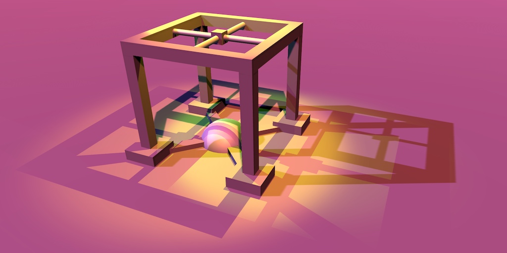
Why does this look so blurred?
@bitter crystal which bit specifically? the shadow, the line?
(I was going to reply saying because it was taken on a mobile phone but figured that would really just be a dick move 🙃 )
Might be something to do with post processing. Kinda hard to tell what part is blurred since it's a photo and not a screenshot.
It will be very hard to comment without seeing the graph
whats the intended look - just a clean line, no gradient?
It might also make sense logging into discord on the computer instead so you can send actual screenshots
(there's a web client if you don't want to install)
(judging from the screenshot alone, which shows a vignette, I guess you have a post process enabled (with bloom), are using HDR, and have put a very bright color into the emissive channel?)
one sec eliote
same blur
Regarding Cam forward rendering doesn't support hdr
Well your bloom's intensity is at 11 so it's going to be quite strong and blurry like that. I think usually you wouldn't really go past an intensity of 1 or 2.
If you aren't working in HDR then the Threshold should be reduced though
what does it look like if you disable post processing? Also, you might want to try it with using point for the texture filtering
I'm afraid it is very hard to see without an actual screenshot though, the monitor/UI looks quite blurry aswell
Also, I'm not hugely familiar with post processing but isn't tonemapping only useful for HDR? And bloom should be applied before tonemapping? (probably doesn't matter actually, it looks like it applies them in the correct order regardless of the order in the volume)
umm apparently i need the bloom for that shader shine effect
disabling tonemapping leads to
more blurring
if disabling the tonemapping leads to more blurring, and given Cyan's comment, it seems like the bloom is a likely candidate for the blur?
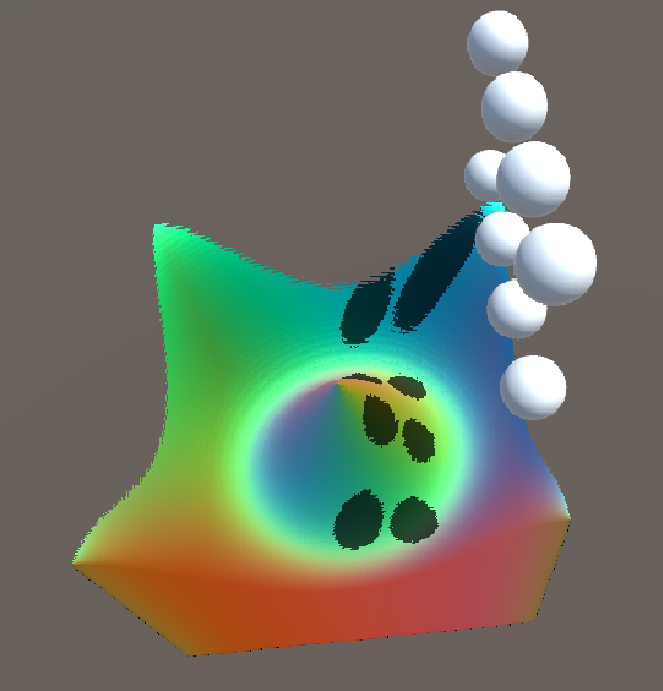
I'm experimenting with PBR world-space UV shaders. I'd like to know how to make my special material render inside the scene view as it's a bit of a pain to start game view every 30 seconds to take a look at adjusting my shader values.
Having some trouble here with following a tutorial, I've went over it 30 times and managed to narrow down what is going on here
per my code, I've got this:
    public void UpdateElevation(MinMax elevationMinMax)
    {
        colorSettings.material.SetVector("_elevationMinMax", new Vector4(elevationMinMax.Min, elevationMinMax.Max,0,0));
}```which effectively passes through Vector4(3,3.4,0,0)
this is re-enforced by the number being passed into the material here:

the number does update if I mess with the elevation settings with the generator
now, this fails to work:

but this does:

Expected output as such:

What is going on here, anyone got an idea?
Ok. something to do with the reference... wtf.
as this works:
oh wow
😄
not bad for first day with unity really
admittedly following the code of a tutorial word-by-word... but I got a good understanding what is going on.
🙂
does anyone know whether it is possible to grab a sprite's "Border"(the one used for 9-slicing purpose) values inside shader ?
Hello I have two questions about ray tracing in Unity,
- How does ray tracing works in Unity? How good is works? Is it really worth it?
- Is there a way to make my game support "RTX ON RTX OFF" that you can just press a key and the game (if some reloading needed it's fine) will switch ON and OFF from using Ray Tracing
admittedly following the code of a tutorial word-by-word... but I got a good understanding what is going on.
@hollow drum Which tutorial?
Or path tracing to be more correct

In this episode we add simple colour biomes to the planet.
Get the project files for this episode:
http://github.com/SebLague/Procedural-Planets
Note:
Two issues have been pointed out which I'd like to address: (will add these fixes at end of next video)
- changing resoluti...
@cedar vigil DirectX12 is more about raytracing. While it's not limited to RTX cards, you can certainly toggle it on and off (HDRP).
Is it worth it... that's a larger question and one still being asked across the globe.
Game devs have been faking it for years and quite successfully, arguably in some instances better and more performant than actual raytracing. But it's not really a debate for here, look around net and make your own mind up / do some testing.
Listen I'm building a game for me and my friends to play and I got an RTX card... It's mostly just for me... so you know.... what did you mean about DirectX12 is more about ray tracing? @thick fulcrum
do a search on internet, you will discover. Or just fire up the HDRP template and activate the highest settings
Can someone help me on how to get the cameradepthtexture in shadergraph or how to get the camera depth based on UV coord?
There's a Scene Depth node. Usually you use Screen Position rather than model UVs. If you just leave the input blank it will automatically use the screen pos.
You should also change the master node to Transparent
If you are using URP the Depth Texture option on the URP asset would also need to be enabled.
Is anyone looking for a shader to pixelize 3d objects? I'm looking for feedback on one I've made
my shader graph unlit shader doesn't work, then when i restart unity, the shader is just gone in the shader graph window
is this a known bug?
@regal stag I am trying to get the depth value of adjacent UV values
@prime timber Then offset the input. Screen Position -> Add/Subtract Vector2 -> Scene Depth. Also bear in mind the value that you offset should be very small, as a value of 1 would be the whole screen width/height.
Can probably divide a value with the width/height from the Screen node if you want it in pixels
How can I change this to have control over top and bottom separately
@frozen mason Probably use a Step node on the Y/G axis from the Split, with edge of 0. That'll give you half black/white which you can use to mask the uvs or texture output, usually by putting it into the T of a Lerp node.
@regal stag Yeah that worked! Thanks
hey guys, i know that when you are using the SetReplacementShader function, you can apply the replacement shader to all RenderTypes by leaving the second parameter as an empty string, but is there a way to apply the replacement shader to all RenderTypes Except for one? or do you just have to manually apply it all?
@regal stag Trying to combine this one with your vertical fog shader. but having trouble with it. I want something like horizontal fog in the far where is the grey line.
@real gorge I can't think of a way to do that directly, other than "manually". BUT, you might think about camera stacking and/or layers to render that one "special" thing separately, at a later time.
I have added this shader to my skybox but now it seems like the fog from settings is not applied here? What I have to do to incorporate fog with the shader?
trying to achieve something like this Top bottom and fog in the far of the camera
Is there any way to use shader graph to create post processing effects in hdrp?
And how can I get started in writing post processing shaders?
@regal stag Hold up. How does adding to the screen position and then going through Scene Depth get adjecent UV depth values? Man I'm so confused lol. If my camera is generating a _CameraDepthTexture anyway can't my make a custom function to access it? Sorry to bother you with this
@prime timber The Scene Depth node just samples the depth texture with the given uv coordinate, and has modes for converting it's raw values into different spaces (linear01 or eye). You could sample it using the Sample Texture 2D node too but the Scene Depth just makes it easier. You could probably also handle it in a custom function, the easiest way would be to include the DeclareDepthTexture.hlsl file and use it's SampleSceneDepth function. https://github.com/Unity-Technologies/Graphics/blob/master/com.unity.render-pipelines.universal/ShaderLibrary/DeclareDepthTexture.hlsl
At least I'd assume that would work, I haven't really tried it myself.
@regal stag Thanks, that clarifies things a bit. Tried recreating roystans outline frag shader in shadergraph for URP but I just can't get it to work
@prime timber This tutorial uses roystans but converted to URP, so might be useful : https://alexanderameye.github.io/outlineshader.html
It includes the part about normals too, which requires an additional renderer feature to get working as URP doesn't handle it by default, (at least in the version they used it might have changed since then). Usually this kind of shader is applied as an image effect / post processing too, which you'd need a blit render feature to handle that too.
Even if you don't follow that one entirely, the Outline.hlsl file which is used in a custom function might give some hints
How does ReadMask/WriteMask work for the stencil buffer?
I don't understand the docs
I haven't really used it but it's related to masking bits, I think with the & / and operator
I think I found a good site explaining it
it's indeed a 0-255 integer used as a mask
indeed using & operator
Yeah, by default the values are 255, (so all 1s), so there's no mask going on
so the stencil buffer is 8-bits and if you have like 00001000
only that bit will be read/written
still not sure in what kind of cases it could/should be used
Yeah same, I find it difficult to really use something like that without knowing a specific use case
I'd assume it would be for use cases where you assign different bits to different things, and the shader you're running will set or clear a value, but you want to ensure that you don't mess up any other bits for other stuff going on. So you mask off only the bit(s) you need to use for that shader's "thing".
ehh really pulling at straws, but can you use it for rendering a cutout through an opaque object?
(but only if your object behind is drawn after the one in front, so you would need to sort opaque objects)
I'd assume it would be for use cases where you assign different bits to different things, and the shader you're running will set or clear a value, but you want to ensure that you don't mess up any other bits for other stuff going on. So you mask off only the bit(s) you need to use for that shader's "thing".
@meager pelican that could be pretty useful then
Hi all, extremely dumb question here but I'm relatively new to shader programming.
I was looking up how you'd get a world or object space coordinates in the fragment shader, and saw someone talking about passing them through from the vertex
And uh, basically what I've done works perfectly and I have no idea why.
Surely the coordinate would be of the vertex, not of the fragment/pixel?
there is an interpolation done behind the scenes 🙂
there is some mention of that in this article: https://docs.unity3d.com/Manual/SL-VertexFragmentShaderExamples.html
But how would it know to interpolate, in that case? I'm just passing arbitrary data through. How does it know it's a coordinate, in a specific space?! 😄
It doesn't need to know it's a coordinate. All data from the vertex to fragment gets interpolated.
Even the space isn't important. They are just numbers
Ah, texcoord are interpolated! Aha!
That answers that.
So anything TEXCOORDn in HLSL is interpolated from the vertex to the applicable fragment in the fragment shader.
Not just TEXCOORD. Position, normals, tangents and color would be too.
Yep, just looking at the section now...
I'll say that's a lot simpler and easier than I was expecting and apparently my Google abilities are worse than I thought. 🤣
Thanks a lot! 🙂
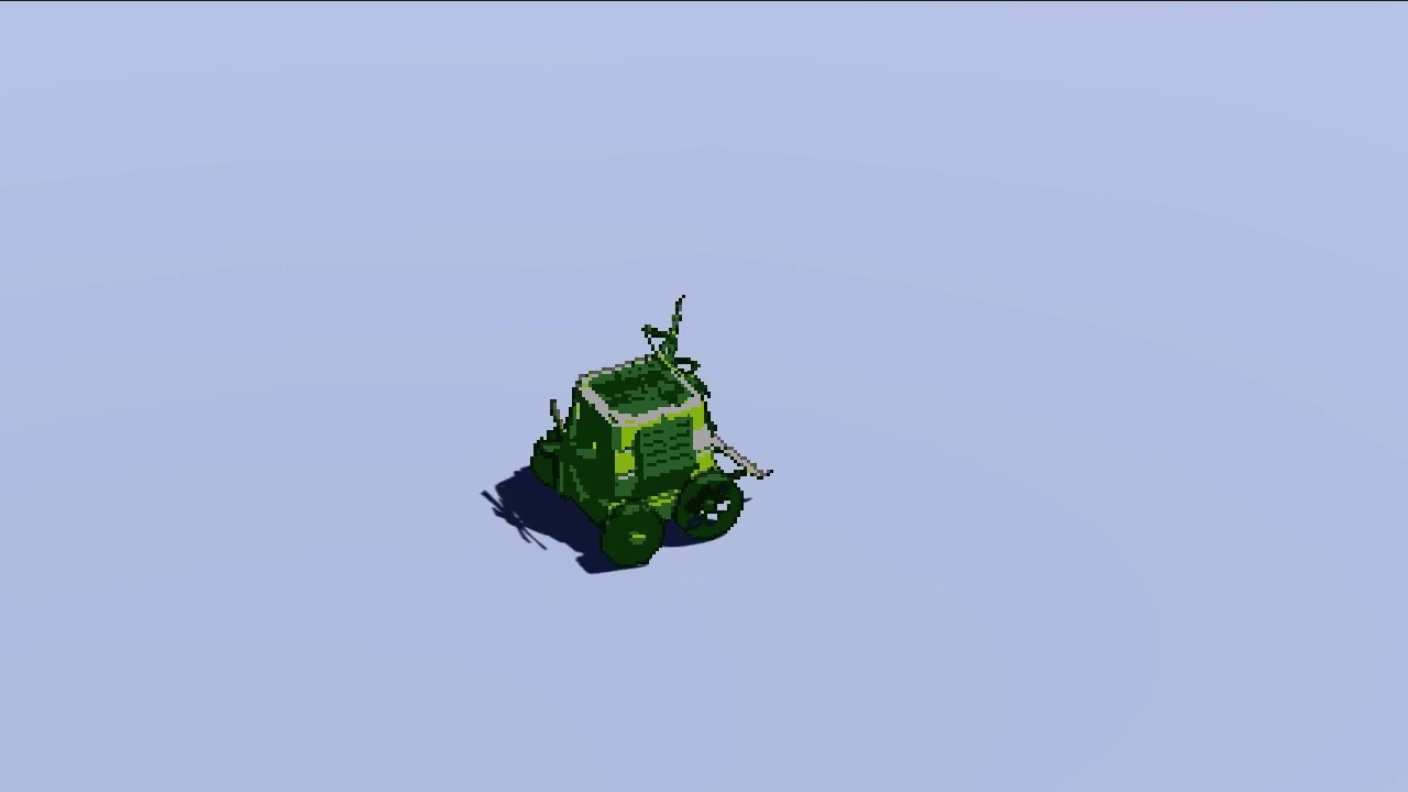
I have some nice occlusion for my amateur pixel art skills now 😄
so, how would you refer to 'the screen pixels occluded by an object' in an article?
I feel occluded isn't the correct word - written to?
occupied?
drawn? rendered? I'm not too sure on the context
drawn is perfect I think
(for context - I'm trying to say that the pixels drawn when rendering pixelised versions of the same model are different)
like in this pic
Are those actually the same model? They just look like different 2D sprites to me. Unless you just used that as an example
they are the same model
I guess rasterised might be the more technical term for how a model is turned into pixels
(I also applied a slightly different color palette to the bottom two, I think PAL and NES from memory)
I think top right is 256 color, can't remember exactly 😄
Ah right, I think that colour palette switch is what was throwing me off
yeah, I never appreciated actually how grubby PAL looks
I think only ever seeing it on a CRT I just assumed the CRT colors were dull!
(the above is a screen effect meant to simulate pixelized sprites)
Well it was fairly successful given I thought they were sprites 🙂
cheers 😄
I'm writing some detail on how it works - basically it needs a post process for the effect in addition to a per-object shader, because the pixels occluded depend on whether the object is pixelized or not
it's probably not the best video because the background is flat, but you can see from the shadow (which isn't pixelised) that it isn't just rendered at low resolution
That's pretty cool. I quite like how it jumps to certain rotations as if it were a sprite sheet, but the flag is still smooth.
thanks!
I tried a few different ways before settling on this method, I also saw people rendering to an offscreen low-res render target and then mixing that back in to the scene, but the shadow casting becomes a nightmare for that (might not be possible for built in, I think it probably is possible now we have SRP)
Yeah, I kinda prefer the low-res render target approach for pixelation - at least if you want the whole screen to be low res, bit different in your case. I've seen some post process effects which take the full-res image then pixelate it in the shader but it feels kinda strange to me to render the scene at full resolution to then throw out most of the pixels.
Maybe it's not that bad though, idk how they compare in terms of performance
The problem with the low res approach is that you can't have motion of individual objects at the screen resolution without pixel creep, you basically have to pixel snap them to whatever the low resolution render target was
The alternative is one (very low res) render target per object, which is alright for a handful of objects but is not at all scalable
That's true
I think that's another thing I quite like about your video. While they are pixels, they don't snap so still look smooth.
Cheers, it took a while! They do snap, but at the screen resolution (rather than the pixelated object's resolution, if that makes sense)
Yeah
if you don't snap at the pixelated object res you still get creep, like here: https://www.youtube.com/watch?v=lO8O5tY-wZI&ab_channel=ElliotB

Pixel creep and scintillation occurs for 3D objects when they move relative to the camera. Small features occupy a variable number of pixels, flashing in and out of existence (scintillation, see eg the window shutters). Edges creep along, giving the object an unsettling wobble.
and then it looks...revolting 😄
Oh, another reason why rendering at full res is nice is that you can do nice DOF post processing (probably a bit much here)
how do i create a shiny shader like in fall guys where everything looks like shiny plastic?
or how do i create that material
Can i use shadergraph if im not using URP or HDRP
I don't think so.
hey guys, i want to know how to get this effect on a unity model.
this is the image used for the runes in blender
I've created a vertex displacement/offset shader but the offset is going diagonal and up instead of just up. Is this a problem with the mesh or a problem with my input texture? Why would this happen?
Can you post screenshot of your shader graph?
the whole thing or just the displacement stuff?
displacement stuff should be enough
using amplify, there's quite a bit of other nodes so please let me know if I can organize this better for viewing
hold on, are those nodes in unity?
how do i get that?

Get the Amplify Shader Editor package from Amplify Creations and speed up your game development process. Find this & other Visual Scripting options on the Unity Asset Store.
$60 yikes nevermind lol, thanks for the help though!
not to bury my original question - but does anyone know why the vertex offset would go diagonal instead of just "up"? The mesh's normals all point away from their surface, as far as I can tell there's no strange rotation magic happening in blender.
correct ... so do I have to like multiply the Y vert coords with the input texture?
I'm not too familiar with amplify, but what happens if you make the X & Z points zero, on your append node?
instead of linking them to your vertex offset
world's longest sight yep that was it... thanks
No prob
The problem with shader graph plugins, is that x,y,z and r,g,b can mess up your train of thought when the previews cant show you what you want to see
Anyone knows how to add height map to shader?
I have 0 knowledge on them, every attempt at learning them have failed, because I don't know the core script for the height maps.
For emission it was basic o.emission, but VS doesn't show anything for shaders
@turbid swift - Unity has a node editor for shaders if you use the scriptable render pipeline - pick either Universal Render Pipeline (URP) or High Definition Render Pipeline (HDRP) depending on what platforms you want to target. As for your original question, I expect you want to do some nodes to work out the glowing color of the runes (by sampling the rune texture, picking the green channel and multiplying by the glow color, purple in your screenshot) then plug that into the emissive node of the shader.
has anyone here ever made a "sixplanar" shader in shader graph? i.e a triplanar shader but all six sides have unique textures. apparantly it is much more difficult than a triplanar one, which I've seen some tutorials on.
if anyone has any pointers or have seen some tutorial on it, it would be highly appreciated.
I think if you just handle the negative normal cases as well as positive it shouldn't be too difficult, but I haven't tried it so I don't know for sure
I made a custom triplanar graph following this tutorial https://www.youtube.com/watch?v=UKIBGb5_JXk
with that setup you could just add 3 more textures and 3 more mask directions, I'd think
@heavy ermine I'm new to this so sorry for dumb questions, but hmm my normals goes like all the way through, like same for top and bottom. How would I limit my mask to only one direction? I'll check out that tutorial as well!
I think the normals on each axis should be 1 to -1, and then I'd use trial and error to eliminate half
so like clamp 0 to 1 and clamp -1 to 0
@heavy ermine Alright, I'll make an attempt 😬 thanks a lot!
@heavy ermine this seems to work. thanks a million! I've been sitting with this problem for a good while.
excellent
@fickle forum Height maps uses the concept of parallax mapping. The cheapest method uses the ParallaxOffset( half h, half height, half3 viewDir ) function (in UnityCG.cginc). You use it to offset the uvs for sampling all textures in the shader that you want the heightmap to affect (except the heightmap itself which would be an input to that function). h is the heightmap, height is a scale factor (apparently Standard shader uses a range of 0.005 to 0.08). The viewDir needs to be in tangent space (might be what space it is for surface shaders, idk? In vert/frag you'd have to calculate it). This method is only an approximation but it's the same as what the Standard shader uses.
@regal stag you typed that to someone who has a general idea about shaders... I don't... Xd
You can find some more info & example here : https://halisavakis.com/my-take-on-shaders-parallax-effect-part-i/
another use case for a heightmap would be vertex displacement, which if you're in HDRP is built into the lit shader
otherwise you'll need to make a shader graph that samples the heightmap with a sampleTexture2dLOD node and then multiply by the object normals then add to object position and then plug into vertex position input in the master node
Depends what you want to achieve. If you actually want to move the geometry then yeah, vertex displacement is the way to go instead of the parallax stuff.
Perhaps by heightmap that's what you meant, I just assumed you were replicating what the heightmap in the Standard shader does but maybe not.
It is worth noting that if you change the geometry in the shader (eg for a terrain heightmap), it only changes the mesh for drawing purposes, and won't change the mesh for other purposes, eg collision
@regal stag I made height map from Materialize software
But I want to change mesh for vehicles (tanks)
Then yeah, probably for parallax mapping if it's adding small grooves/details/imperfections etc. Hopefully the example I linked helps.
(I suppose it could still be used for vertex displacement also, but depends how close up this is going to be viewed and whether the geometry needs to be actually moved or just give the illusion of movement like the parallax. If it's just small details the parallax offset is probably enough. You'd probably also need tessellation if vertices were offset).
I'm on mobile at work atm, but ima look thru it when I get home
have i done something wrong? xD
Im not sure why its not transparent around the edge of the particle... it should be
is the master node set to transparent, not opaque?
yeah I'm a bit stumped, if you set the alpha to one and plug the alpha from the texture into the color to see what the alpha looks like, how does it look?
Its the same :/
only the default particle works, any other particle textures ive made do not work
Im going to restart. it might be a haha unity thing
what do your settings look like for the texture asset?
ok. definately not a unity thing
@teal breach
ok... putting the alpha clip to 0.001 fixed it. i hate this
eurgh
but why is my question 😂 😭
I think this is because the alpha is outside of the 0-1 range
Oh wait no, you are using additive blending?
Additive doesn't tend to rely on alpha, it uses the colour and adds it to the colour of the current pixel. So in order to get transparent you should be outputting black in the color part. (since adding 0 won't change the current value)
I think if you multiply your color with your alpha channel you'll get that
With the default particle, I think it's not based on the alpha channel but black & white already, so that's why the default one works but yours doesn't
ah i see. if i keep the alpha clip at 0.001 is that fine? or will that cause some performance decrease? @regal stag
@wary horizon Not sure. I know for mobile alpha cutout/clipping is avoided because it is more expensive for that platform (though why I'm not sure). For other platforms, it's probably not as bad but it's not really needed here. If you multiply the color & alpha it should fix the blending issue without needing the alpha clip.
Which color? Vertex color or particleColor
Uhh both. You are already multiplying the two alphas together, so should be able to multiply that with the final colour instead of putting it in the alpha master node input
Though more importantly it's the alpha channel from the texture that you need to use, that's already being multiplied together too though
does anyone know why my collapse regions are behaving so weird?
generally, the indentation and collapsing are acting really weird when editing shaders with vs
Hello, i am using this shader graph but i'm having issues with a Quad with a sprite texture
The shader is applied to a cube and i got a separate Quad with a sprite
As you can see the quad wit hthe sprite is inside the cube but it's displayed on top of the cube
when i move it back 0.1, it is suddenly behind the cube
why are my UVs distorted when I build the project
?
in the editor those circles appear just fine
can i ask about material here?
if not i will delete it
i have a AO and roughness texture
and im not sure where can i put it in my material
@deep finch The AO texture would be the Occlusion parameter. Roughness is a bit more tricky, as unity doesn't use roughness - but smoothness. You need to invert the texture and place it in the alpha channel of either the metallic texture or albedo texture, and set the smoothness source setting to match that. Should be able to find more info here, and it's related pages : https://docs.unity3d.com/Manual/StandardShaderMaterialParameters.html
thankss
I'm just messing around with shader graph trying to learn it, how could I change the colour of this?
@iron reef the colors you see there are just visualising the values of your 4-element UV vector (visualised with channels as rgba, black being rgb=(0,0,0) and white being (1,1,1))
oh okay ,maybe I should learn more before I go messing around with UV stuff then
And red being (1,0,0), green being (0,1,0) and yellow being (1,1,0)
If you wanted to obtain a vertical gradient like that where you can switch the colours out, you'd probably do something like this
ah lerp, that's the keyword I needed to hear, completely forgot about that
thanks
shader graph is pretty cool shame it needs urp though
Any fixes for the transparent sprite depth sorting issue in unity?
Where transparent sprites are displayed in front of 3d objects
@marble jasper they should still respect depth testing?
Only when they are fully behind the 3d object
Is the object transparent too?
If the 3D object is drawn in the opaque queue they should respect it
Transparent materials don't write to the depth buffer, so they can't be sorted based on depth information. Opaque objects do, so you can depth test against them
(sorted is the wrong word there - I mean depth-tested against other transparent objects really)
on HDRP when I enable Refraction I get the following error. And the variants needed to render the material fail to compile.
Shader error in 'HDRP/Lit': 'SAMPLE_TEXTURE2D_X_LOD': Too few arguments to a macro call. at /Users/Otaku/Documents/Git/AtomicAtom/2020.AtomicAtom.Puzzle/Game/Library/PackageCache/com.unity.render-pipelines.high-definition@8.1.0/Runtime/Material/Lit/Lit.hlsl(1796)
this is with the default Lit shader
Sounds like a bug. Might be able to try newer HDRP versions and see if there's any change
unfortunately, there are no newer versions of HDRP. Im using the latest.
unless I want to try a preview version
I think there is an v8.2.0, though unsure if it'll make much of a difference. Might need to upgrade unity version to even get it in the package manager
previews up to V10 show for me, as im using 2020.2 beta.
after restart ill give one the thr HDRP previews a try
first I want to see if it might be an error specific to DX11, so switching to vulkan.
yeah, switching to vulcan as well as upgrading one version did not resolve thi
im trying to access the depth texture here, and needless to say, it aint looking right lol
the way i calculate screenpos should be correct
-the vertex offset is for water waves, you can ignore that part
depth texture should also be correct
idk what im doing wrong
I think you also need to do i.screenPos.xy / i.screenPos.w to get the correct screen pos in the fragment
ohhh ok thanks!
that fixed it
i assumed that'd be done in the computescreenpos function 😛
I guess ill try downgrading to 2020.1.0f1
@grand jolt I had a look at the Lit.hlsl code, other than it being on line 1797 (rather than 1796 as the error mentions) it seems to have 4 arguments, which I think is what is required for that macro. The only thing that jumps out at me as being a bit strange is the fact a comment is half-way through it, but surely that isn't what is causing the error? https://github.com/Unity-Technologies/Graphics/blob/289e645f98ef9abfcb8f8a808c8684de60cdb2ac/com.unity.render-pipelines.high-definition/Runtime/Material/Lit/Lit.hlsl#L1796
the comment stands on it's own line but the formatting there reminds me of another bug related to spreading statements across multiple lines.
Perhaps you could edit the file in your project and see if it fixes it
yeah, when im done rehashing ill give that a go.
ok, so the whole depth thing is working, but for some reason there is a weird white bar over the water
at the bottom of the screen
which moves with the camera
Ground under the water plane might be too close
in a shader that i had before (which i made with ASE) it didnt happen
but well, that shader suddenly broke down
adjusting that line (combined with deleting library folder) seems to have fixed the refraction
How are you calculating this? something like saturate(1 - (depth - surfaceDepth)) ?
almost
Yep, thought so
I've done the "depth difference" method in shadergraph before too and encounter the same problem. It's not very accurate and when viewing from shallow angles the "foam" around the edges gets kinda squashed
One method that I've used instead is reconstructing the world position from the depth value, from there you can use the y coordinate to obtain a gradient like that on the terrain
I think it was, _WorldSpaceCameraPos - (worldSpaceViewDirection / surfaceDepth * screenDepth)
worldSpaceViewDirection being _WorldSpaceCameraPos - fragmentWorldPos too
oh! oh! hang on
i realized i was able to revert my old water shader filr
lemme check out how it didnt happen there
Okay, it might have been some extra offset or the two planes weren't as close before
nvm
it also happened there
it just was never visible enough to notice it
still, a better method would be neat
The whole "reconstructing world pos from depth" is a great thing too, can use it for other effects like projecting underwater caustics textures
ohhh i did think about how to do that
but didnt think it'd be possible
lemme try the method
Yea, try the above. It's easiest to output frac() of that to visualise the position
Well if you just output the .xyz you'll be able to visualise the entire position. Just in case I converted the calculations wrong
Yeah that.. doesn't look right 😛
figured
definitely not right lol
viewdir is float3 viewDir = normalize(UnityWorldSpaceViewDir(i.position));
Ah right, don't normalise the view dir
You can call it something else other than "dir" if you want. For some weird reason shadergraph's view direction isn't normalised but they still call it a direction.
Also I think UnityWorldSpaceViewDir expects it's input in worldspace if it isn't already
Yay
Now you just need to take the y axis for the gradient. You might need to offset it if the water plane isn't at y=0.
Oh right.. Hmm
I guess the same calculation could be used to offset it again
Or maybe i.position should be the offset one? I wonder if that would work?
Not sure if that's right or not either. Might have to try the y gradient now and see what it looks like..
hmmmm
Hard to tell if that's right. Some parts look thicker than others.. so not sure
it does look a bit off yeah
That little spike on the right side is following the vertex offsetting though
But yeah, the rest looks off
tho, im wondering
how would i do that underwater effect
i could use these coords at least for that
The underwater caustics thing I mentioned?
ye
Hmm, well I usually use the X and Z coords from that position as uvs into shadergraph's generated Voronoi node as that gives a similar effect to caustics as it rotates.
Could likely use a texture too though. Maybe something like what's done in this tutorial : https://www.alanzucconi.com/2019/09/13/believable-caustics-reflections/
ayyy thanks! I'll read through it
The important part is using the .xz of the position as that'll "project" the texture through the y axis. Similar to planar mapping / world space uvs, but rather than it being the fragment's world pos, it's the scene's one.
How does this fog effect work?
HDRP volumetric fog is not suitable, right?
Cause this one is very localized.
Maybe something based on particles? Alpha controlled by depth?
That coukd work. You mean fade out as player gets closer?
More like the "soft" particles option. How it blends in with objects in the scene rather than clipping through stuff. But you might also need to fade as the player/camera gets closer as well.
anyone know why my normalize is a Vector1 rather than a 3 like it is in the tutorial I'm following?
If you put a Vector3 into it, it should change to a 3 input
https://i.gyazo.com/b9d692d6b2055428d5b4624cd24f1a40.mp4 works like a charm owo
just gotta make it blend on proper heights etc
but otherwise, this is epic
thanks for the help @regal stag
i guess i can use the effect i used before for the close border effect, and the stuff you've shown for the rest
With shader graph, how can I make something like an if statement?
I want:
If autoAnimate = true, then output Sine Time, else output 1
not sure how to do that though
There's a Branch node
ah thanks
I think fog volumes can be local areas, but they're cumulative if they overlap....
If I read this correctly:
https://learn.unity.com/tutorial/creating-volumetric-fog-19#5dcd7957edbc2a001f012ae7

Unity Learn
Most implementations of fog, such as exponential or linear fog, are computed at an object’s surface by the Shader that the surface uses. At most, this is once per pixel. Volumetric fog, on the other hand, is computed at intervals in the empty space in front of the camera, inde...
@meager pelican it's mostly just that I don't think it can do multlayer 3d noise.
Can you set properties inside a shader graph, I want to do a runOnce kind of thing but not sure how
because I want it to be usable multiple times, but just stop repeating like sinTime does
The shader can't update it's properties no. It would be easier controlling a Vector1 (aka float) from a C# script, to act as the time rather than relying on the built-in time/sin time. That way you can start and stop it, or restart it, whatever.
Can either do that via material.SetFloat(reference, value) or Shader.SetGlobalFloat if you want it shared between multiple shaders / easier static access.
is this normal behavior for unity's built-in fog? the direction of the scene view/rotation of the object seems to affect the density of the fog on the scaled up cube :/
i made my own fog that doesn't have this issue so idk what the dealio is. maybe somethin to do with fog coordinates not interpolating correctly or somethin?
Normal maps being weird episode 10,000.
Anyone know why this isn't affecting the shader?
where does it go to the right?
it goes straight in to a PBR Graph Normal.
change Type to Normal?
I got a strange bug myself. My ShaderGraph shader isn't casting shadows, so I checked the generated shader code. It seems to define #pragma vertex vert and #pragma fragment frag but then goes on to define a SurfaceDescription SurfaceDescriptionFunction(SurfaceDescriptionInputs IN) and doesn't actually define the frag or vertex functions for the Shadowcaster pass. Is that usual?
I was slightly surprised, I thought if this was straight ShaderLab that would be an incorrect definition
I never looked much under the hood for the generated code before, so perhaps that is just normal behaviour and the bug is elsewhere
FWIW the UniversalForward pass also defines those pragma and then defines a surface instead, and it seems to work fine.
@teal breach It might have some #includes which contain the vert/frag.
Is it just that shader that isn't casting shadows?
Maybe check the mesh renderer to make sure it hasn't disabled shadow casting too.
definitely the shader
something to do with my custom alpha node
it returns the value 1.0, but that still breaks the shadow cast
whereas if I uncouple the node, and put 1.0 in manually through SG, it compiles fine
the function is literally just doing #ifdef SHADERPASS_SHADOWCASTER return 1.0 basically
Hmm, and that's not being used for the alpha clip threshold is it? Just alpha?
no, the alpha clip threshold is defined the same way both times
(just 0.1 in shadergraph editor)
Weird. I'm not sure why it wouldn't be casting shadows then 🙁
Only thing I can think of is it's discarding / clipping. Or I guess vertex offset somewhere else, but unless you are doing some vertex stuff I doubt that's it either.