#archived-shaders
1 messages · Page 168 of 1
hmm, actually thinking about it, what I actualy need is the angle between the thing being rendered and the player's position...
is the player position the same as the camera position?
not the normal of the face - I don't care which way the thing is facing, just that it is located above teh player and not more than 15-20 degrees
aye
(I want to create a cone of visibility above the camera...don't care which way it's facing etc, but if the player looks up, it should see everthing directly above + a small angle off
@tidal rover What doesn't seem right?
if I do that everything is rendered in wireframe instead of just that camera
        RenderPipelineManager.beginFrameRendering += (context, camera) =>
        {
            foreach (var camera1 in camera)
            {
                if (camera1.name == "Wireframe")
                {
                    GL.wireframe = true;
                }
                else
                {
                    GL.wireframe = false;
                }
            }
        };

        RenderPipelineManager.endFrameRendering += (context, camera) =>
        {
            GL.wireframe = false;
        };
this renders everything in wireframe for some reason, not just the wireframe camera 🤔
@low lichen
Wouldn't you want beginCameraRendering not Frame?
that didnt do anything
Unless it treats overlay cameras differently maybe
Didn't do anything? You mean it didn't draw anything in wireframe?
I can see why the snippet above would render everything in wireframe
As long as the wireframe camera is among the cameras rendering for that frame, the whole frame is wireframe
I need to change these settings per camera, not per frame rendered...
So using the camera specific events would make more sense
But I don't know why that doesn't work
Maybe log the camera names and check whether the wireframe camera is actually being included?
        RenderPipelineManager.beginCameraRendering += (context, d) =>
        {
            GL.wireframe = d.name == "Wireframe";
            Debug.Log(d.name + " " + GL.wireframe);
        };

        RenderPipelineManager.endCameraRendering += (context, d) =>
        {
            GL.wireframe = false;
        };
@regal stag @low lichen
it seems to be doing it, but it doesnt respect it when rendering
Hmm, this appears to be working for me, but I think it's basically the same as what you have. ```cs
public class WireframeTest : MonoBehaviour {
void Start(){
    RenderPipelineManager.beginCameraRendering += Wireframe;
}

private void OnDestroy() {
    RenderPipelineManager.beginCameraRendering -= Wireframe;
}

private void Wireframe(ScriptableRenderContext context, Camera camera) {
    if (camera.name == "Overlay Camera") {
        GL.wireframe = true;
    } else {
        GL.wireframe = false;
    }
}
}```
I'm in Unity 2020.1.2f1 btw
Same. I assume you are running a webgl build right?
So I'm sure it's not just not working in webl but works in Windows builds
Oh right, I was just testing it in pc standalone atm
Uuuh OK wtf. My pc decided to throw out my gpu
i could not work out the whole render pipeline jazz
My screens just froze and I can't get screens to turn on. They don't receive input
I had this plan to write an entirely new scriptable feature to render my scene with odified lighting (where the lights render with an attenuation if you're underwater, giving us volumetrics and falloff and the like)
that didn't happen so im stuck playing around with a blit pass to "hack" it
@tidal rover Made a webgl build and yeah it doesn't work. It probably doesn't support the wireframe rendering so you might need to use a different method. Maybe using custom shaders instead.
I guess that would be the alternative
I know Catlikecoding has a tutorial on wireframe shaders, but it uses barycentric coordinates (so you know how close to an edge you are) produced in a geometry shader. But I think geometry shaders also aren't supported in webgl, so unless you can find another way to handle that I'm not entirely sure how you'd do it.
why is webgl being such a nuisance.
I've done things with storing barycentric coordinates in vertex colors before - but since they share vertices it's very awkward to setup, without splitting every face & duplicating vertices.
honestly, it was for a gamejam that ends in 2 hours. and I just published a windows build instead. I just thought I would get more people to play it if it was a web build
I have a working windows build. but I wanted to have it working on web build too
Ah I see
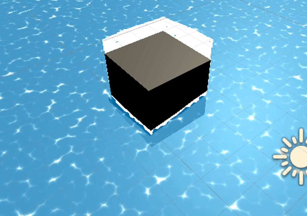
this is the game I submitted
each triangle is outlined with the wireframe becuz if they get hit they get destroyed
but when there are multiple adjacent polygons that get deleted, it becomes very hard to see where you can click on the side to generate a shield
@regal stag
Oh okay, with just a single model you could probably just use blender's wireframe modifier on it and have another separate version to render alongside it.
Hi, what is the 4th component in the Screen position node when set on raw ?
@lusty badger It's basically the depth to the fragment position, which is a quirk of how the position is calculated. The node needs to be set to Raw as in Default every component is divided by that component (perspective divide) in order to get the final screen position (and dividing A by itself would just turn it into a 1).
I believe it's equal to the -Z component of the Position node in View space.
Wow, thanks! It finally makes sense why my shader worked when I negated it. 😄
hmm is it possible to have a material with only the shadowpass and another material with the forward lit pass in URP and have them drawn out separately?
for example:
Lit Material <- Renders the mesh with Graphics.DrawMesh...
ShadowPassMaterial <- Contains only the ShadowPass in the shader to render out the shadow separately given the same mesh (issued with Graphics.DrawMesh)
does anyone know how to have an outline shader that works properly with DOTS ?
(I need an outline effect that works with only one material)
Hey, I have a roughness texture that I want to use using Unity's built in render pipeline (no URP no HDRP)
Is there a way for me to use the roughness texture alone without using some weird metallic thing?
With the default shader you’ll need to put it in the alpha of either the albedo or the metallic
If it’s really roughness it also needs to be inverted
Agreed 😉
guys I'm making a game inside a sphere with inverted normals - a photosphere
and there is a particle that doesn't work inside the sphere, all the others do
I figured this is a shader problem, with the shader queue or some shit
anybody had this problem before and knows an easy fix?
are there any Tutorials to get the main light in shader graph?
For LWRP/URP, yes : https://blogs.unity3d.com/2019/07/31/custom-lighting-in-shader-graph-expanding-your-graphs-in-2019/

Unity Technologies Blog
With the release of Unity Editor 2019.1, the Shader Graph package officially came out of preview! Now, in 2019.2, we’re bringing even more features and functionality to Shader Graph. What’s Changed in 2019? Custom Function and Sub Graph Upgrades To maintain custom code inside...
How can I convert a tangent normal map to an object normal map?
I got it. XNormal has a built in feature.
hi guys, I made a shader graph to displace vertices using a vertex position on the PBR Master node
when I apply the graph/material to a regular unity plane model it looks good, but a little jaggy because of lack of verts
I made a 100x100 vert plane in blended, and imported it to unity at a scale of 1 in FBX format
the model imports 1 to 1 with these settings (tested on a cube)
but the intensity of the vert position effect is excessive by orders of magnititude
anyone know what might be causing this? I'd prefer to fix the export rather than dial in the shader for every model
Does anyone here know how to set a gameobject to have an image texture using the Universal Render Pipeline?
Did you apply the scale to the plane in blender before you exported it @umbral glacier?
It's worth noting as well that the plane is unity is 10x10 units while the quad is 1x1
Hey! I want to control the amount of influence the light probes are having on my material, so I'm using the Baked GI node and adding it to the albedo, but I can't figure out how to blend it properly. Colors get funky or pale no matter the blend mode.
@signal rapids I believe you just want additive. So an Add node should be enough.
Thanks @low lichen ! Any other pointers for playing around with Baked GI? I'm not finding that much info about it online besides Unity's own docs
I've never used it. I've only worked a little bit with the code side of baked lighting data.
Have you accessed the light probes via custom node, possibly?
I don't really use Shader Graph much
But that's additive too, so you should be able to just multiply the color if you want it darker or brighter.
Thanks, I'll play around with it
Are you on URP?
For URP, there's a SampleSH function defined in Lighting.hlsl.
You give it a world normal and you'll get back the blended light probe + ambient color for that direction
You should be able to do that in a custom node @signal rapids
No, I'm in HDRP actually. It's proven difficult to access certain light features because of it!
@low lichen Have you done any fiddling with HDRP?
Not much. Are you using deferred or forward rendering?
Deferred means lighting calculation is deferred to a final step. You can't have a material that does custom lighting.
That's only possible in forward rendering, where each object is responsible for applying its own lighting.
HDRP defaults to deferred, I believe.
Yeah I think I'm using deferred
Then your material is just drawing the unlit albedo, world normals, depth and specularity into separate textures and those are all used later to apply lighting to the whole scene.
Ah okay, then that's why I see discussions about the difficulties of custom lighting in HDRP
Hi guys, i'm following some tutorials on shaders graph but I don't always understand the logic behind some nodes : in my case, i'm trying to understand intersections.
My problem here is the W component of the screen position node : I can't figured out what can be the value returned by this W
Someone asked what that was above too, #archived-shaders message
If I multiply the scene depth by the far place, I can imagine that it will give 50 for example. But what's that clip space position ? Isn't that supposed to returned a number between 0 and 1 ?
Oh thanks I'll take a look at this !
The range of the w component could be higher than 1. The Linear01 * far plane (or Eye space) and ScreenPos.w is basically in the same scale/ranges (between 0 & far plane)
The logic that handles the intersections is : If the scene depth and screenpos.w depth values are the same, then subtracting them produces 0/black (which becomes 1/white with the One Minus). For scene depth values that are further away the subtract could return a positive value, which produces a gradient towards black (0 or negative) with the One Minus.
There's one thing I don't understand now : why is the Scene Depth higher when the object intersect with another one ?
The scene depth samples a texture containing the depth values of opaque geometry. For shaders that are transparent, they aren't rendered to that texture so allows us to obtain the depth of objects behind it, which are further away from the camera so have a higher depth value.
So that's why this node doesn't work on opaque geometry
Thank you so much ! By the way, I found your Wordpress. It's really really cool I'll add it to my favs
Hey. So I was just getting started with shader graph. I made this little shader and dragged it onto my material. But the material did not change to the yellow preview as in the shader. Instead it just stayed grey. Any ideas?
Have you saved the graph? (top left corner, save asset)
Thanks. (Yikes 😉 ) I thought Ctrl + S would work but apparently I need to press save manually
Hey, I'm a bit new to shaders, and I want to be able to make materials that act like masks between each others. I've look a bit into stencil operation and so I would like to apply that to my materials. Ultimately, I'd like each of my sprites to have a ref, and that if one sprites with a lower ref superposes with one with higher ref, the intersection would not render on the sprite with lower ref. I'm kinda lost on how to make that tho, any advice?
Does anyone know of a good open source library for a custom light probe implementation? Not placement of Unity's light probes, but a totally custom light probe
Even if it's for a different engine, just looking for a point of reference for generation and shaders
@uncut robin I think you would want a stencil pass like this to achieve that : ```
[IntRange] _StencilRef ("Stencil Reference", Range(0,255)) = 0
...
Stencil {
Ref [reference]
Comp Greater // only render if reference > stencil buffer value
Pass Replace // if pixel was rendered, set value in stencil buffer to reference
}```
However note : the stencil works on all pixels of the rendered triangles/geometry, and will still mask even if the sprite makes that pixel completely transparent. (though might not with discard / alpha cutout).
It would also mean a lot of materials depending on how many sprites you are applying this to, and it would probably break the batching that sprites use and be more expensive to render.
Ahh, apparently both (Stride) Xenko and GoDot have a light probe system that's opens source
@regal stag I don't plan on using to often, it's just that the default sprite mask that's built-in won't work in my case. I'm using IK 2D to animate monsters (RPG style), but when decreasing the alpha, layers that superposes kinda mess it up. And since the sprite is distorded, the usual mask won't do except if I update it every frame which seems expensive (?)
Also now that I think about it more, that would require rendering the lower stencil values before the higher ones in order to work correctly.
There's just too much I don't understand about how to write a shader, I'm keeping your solution in mind while I inquire a bit. thanks 🙂
I see. Another solution might be to render the entire object at full opacity to a render texture and then adjusting the alpha of that as a whole. I'm sure someone mentioned that in here not too long ago too
That solution also crossed my mind 🙂 I don't quite know how to get that texture tho.
I imagine something like another camera rendering objects (with an appropriate culling mask) to a texture. There might be another method though that I'm not aware of.
Cool thanks 🙂 I'm gonna look into that.
I don't understand how all that works tbh ^^ would that work dynamically? If an individual sprite moves does the texture changes as well?
The second camera would render it's contents to the texture every frame, so yes
I don't really know how expensive it would be though, and if it's for RPG monsters you'd need to do it multiple times too (unless they all fade out at the same time or something).
So the main camera doesn't render the monster at all then? And the second renders the whole thing after?
This is only for the death animation, where there would fade away
Yeah, the second camera renders the monster's sprite to a texture. You then apply that texture to a quad that the main camera renders, where you can also adjust the alpha to fade the entire texture.
Thinking that you could probably also only handle that when the monster is dying and render it normally otherwise, but that might be difficult to setup
That was my intention at the beginning, just swap the whole object by an image of it that just fades away in its animation. This is probably the easiest way to do it, although in that case it would not be dynamic
And I also managed to mask UI with materials so I figured this was a better way to do it as I would just need a material which is reusable for all the monsters I would have
Anyway, I appreciate the help thanks. I'll continue looking for the solution and in the meantime learn a bit about shaders which I feel like it's overdue ^^.
How can I get the tangent-space view direction in a fragment shader
@civic finch This should help https://halisavakis.com/my-take-on-shaders-parallax-effect-part-ii/
uh so
when i debug the value of that calculated viewdirtangent
it's always (1,0,0)
@civic finch is your vertex xyz definitely in object space?
also this might sound daft because I've never had reason to use tangents - but isnt the cross of a normal and a tangent just the other tangent?
this code is just copied from the internet but by my understanding yes, your axes are tangent, normal, bitangent (other tangent)
and the _WorldSpaceCameraPos being like this seems like a weird issue
so you are trying to get some axes aligned to the object surface and dot those with the view dir?
if your normals were~~ not normalized~~ length 0 you would get always red, because both bitangent and normal would be 0
Haven't really had that problem before. How are you testing _WorldSpaceCameraPos? I take it outputting it as a colour, but are you around the world's origin (0,0,0)? If not, it would be best to test it there, as any x value higher than 1 and y and z value below 0 would produce red.
yeah i think i got the camera to pass through 0,0,0
How can I give emission to an unlit master node?
what
i mean it already has emissino
emission
it is unlit
unless i'm really misunderstanding what you're asking
weird so _WorldSpaceCameraPos is available in surf but not vert
huh unlit doesn't have emission for me
no but
unlit is emissiono
if by emission you mean a colour on the material without lighting
uh thats not emission though
without GI that is what emmision is
How would one create a slowly moving gradient noise? When I try to input time into UV of the noise it just flashes black and white
You need to offset the UVs by the time rather than replacing them entirely. Easiest to use the Tiling And Offset node to do that
And put the Time into a Vector2 node to control which axis is offset. Or both
I have this foam going on a certain direction. I'd like to make it go on a direction perpendicular to the tangeant of the intersection. So I thought about a cross product between the tangeant vector node and the normal vector node. Does that sound a good idea ?
Hey guys. Looking for help with making custom slash shader with shader graph. Im not good at all with SG but trying my best.
Wanted to achieve this kind of effect but Im kinda far from it and also this guy uses Amplify Shader instead of Shade graph and dunno if I can translate it to SG
https://www.youtube.com/watch?v=Cczp1muRtiU
@regal stag my master help me please 😄

Создание эффекта слеша от меча с помощью системы частиц на игровом движке Unity. Game effect tutorial.
Если вы подписаны на мою страницу Patreon, то готовый эффект вы можете скачать здесь: https://www.patreon.com/posts/29675650
------------------------------------------------...
This is what I got XD not at all loking like those in video
My SG. I think I need better textures to get the effect
I think you need to check how you are handling the alpha, as currently you are connecting a Vector4 (pink lines) to the Alpha input which is a Vector1 (light blue). That means it's taking the first component of the vector4, aka red, not alpha.
You'd probably want to Split and take the A output instead.
Alternatively - I'm not sure what your Main Texture & Mask textures are, but if they are greyscale you could take the R output instead of the entire RGBA to keep values as a Vector1. In that case you would then split the Vertex Color and multiply the mask part with the A component, so that the alpha of the particle system component is taken into account too.
Hey, could someone explain me what exactly makes my shader stop working as soon as I switch to forward rendering (shader noob here as you might have noticed 😄 ) ? Thank you 🙂 https://pastebin.com/PrF2esxn
Pastebin
Pastebin.com is the number one paste tool since 2002. Pastebin is a website where you can store text online for a set period of time.
Are you supposed to make shaders in unity or in blender?
In Unity, either via coding (Shaderlab + cg/hlsl) or a node based editor (e.g. Shadergraph, Shader forge, Amplify). I think there are ways to import the texture mappings from blender to unity's standard shader, but not the exact shader.
@pastel sigil Not too sure, but it's possible that the depth texture isn't rendered in forward by default. I think you need to enable it in a C# script using camera.depthTextureMode. See https://docs.unity3d.com/Manual/SL-CameraDepthTexture.html

@regal stag That did the trick. Thank you so much!
ah so is there no point in doing shaders in blender?
Some of the logic learnt can likely carry over, but you can't use the blender shader in unity as far as I'm aware.
hmm
I'm working with a friend who knows blender
and we're just trying to figure out who does what
and it's pretty confusing
so all lighting is also done in unity?
basically lighting, shaders, and texture animations in unity; models, texture maps in blender
is what i'm getting atm
Yeah. If you have 3d characters you can rig and animate them in blender, and import those too.
right
bones and rigging stuff in blender
and you just export fbx for models and baked image textures for textures
Yep
Hi all, is it possible to decompile shadergraph shaders? I know how to do it for written surface shaders, but I can't find the equivalent button to push on shadergraph
I'm trying to track down a nasty bug which only seems to happen for GL ES 2.0, and I think it's due to some incorrectly compiled shader code, but I would love to be able to check that
I think it might be in the inspector window when the shader graph is selected.
yes! it is! thanks very much @regal stag , I was looking on the material
Which part do you mean, the thin line or the iridescence?
the holographic metal kinda look
i downloaded this off of somewhere actually but the texture is for black shoes but the file includes a few more things but i don't think they are unity related
so i'm trying to see if there's a unity shader like that
I've never implemented that before myself, but I expect you can achieve by taking into account the surface normal, light direction with respect to the camera, and using those to sample some sort of iridescence texture (a rainbow, basically)
perhaps someone here has already done it before and can comment?
just try messing around with plugging the normal into a color ramp and see what you get tbh
and i got my parallax shader working
thanks for all the help/fixing my idiocy in the past few days :)
Is their anyway for me to make a shader value slowly increase over time without a script?
Im trieng to change a vector 1 from 0 to 1 in 30 seconds
No, shaders can't hold any state by themselves that persists for multiple frames
Not really. There's a _Time variable that unity sets but you would still need a way of triggering it.
Gotcha, anyway i can use the TimeSin variable?
Hey, I'm stuck on trying to use the stencil shaders, can anyone help me out? These are the shaders https://hatebin.com/efncuomrhe https://hatebin.com/qwtobvbelh
Can't really see what's wrong with them
Exactly xD
It's like the ref from the first shader doesn't get replace, so if I set Comp Equal to 0 it renders and to anything else it doesn't, regardless of the position relative to the other sprite
man
tryna make a nice shader
with a stippling effect instead of fading the alpha
and i have it
but I'm trying to get it running on "lesser hardware"
and it lags terribly
what have I done wrong
i can post code but it's basically this https://youtu.be/--GB9qyZJqg?t=283

I created a little generator for coming up with (mostly terrible, but occasionally interesting) game ideas. I then tried making a little game based on a generated prompt about ghosts and beekeeping.
You can try the idea generator online here: https://seblague.github.io/ideage...
hmmm maybe it wasnt the shader
idk tho
i dont think an RTX2080s is a fair comparison to a 2016 snapdragon
Might be some horrific bottleneck
Could you post the whole thing?
And do you get the lag on an emulated mobile processor or an actual phone or a desktop gpu?
Hello, I'm working on a project that generates topography maps from heightmaps. The first gif is what I have, I generate a mesh from a heightmap and then slice it to get different height bands. A topography map is basically a bunch of concentric bands marking elevation.
My question is: what's the best way to go about turning the pixellated lines in the bottom of the gif, into something resembling more contoured, vectorized lines in the image? I'm unsure if just bilinear filtering it a ton is the right path
this is the reference image for the desired final product
@sacred ether You likely want to treat it as a distance field and smoothstep the edge of it to get AA lines.
search around for SDF font rendering and you'll get a good idea of how to get stuff like that..
sure, i've never heard of distance fields before. thanks for the heads up!
Yikes... I was trying out Amplify Occlusion. Went from 4 draw calls due to GPU instancing to 153. Likely, one per object?
Hey all! Just a quick question that I'm hoping someone has a quick answer to: What's the difference between create --> shader --> vfx shader graph and create --> visual effects --> visual effect graph ?
VFX Shader Graph is basically a shadergraph that you can use in the output node of Visual Effect Graph that is responsible for the particles. You can expose some of the shader graph properties and then assign it per particle in the output node. You can add a lot of detail and cool effects to your partixles if you use the VFX shadergraph :D
Or you could just say
VFX Shader Graph = shader for particles
Visual Effect Graph = particles
Awesome. Thank you so much @lusty badger!
Hi everybody, I have this foam going on a certain direction. I'd like to make it go on a direction perpendicular to the tangeant of the intersection. So I thought about a cross product between the tangeant vector node and the normal vector node. Does that sound a good idea ?
Doing a cross between tangent and normal will only give you what is called the bitangent (or is it binormal ?) vector of the geometry, not of the intersection.
You could however get the intersection "direction" using DDX and DDY nodes.
Hey can anyone help me out?
Better ask your question directly 🙂
Alright, so im trying to get an effect like this, but im not exactly sure which nodes to use for the grayscale, and the color palette

reddit
1,805 votes and 55 comments so far on Reddit
Thanks I'll give it a try
What?
I'm not sure if this is node using post processes (I think it is), but it's pretty simple : The objects are rendered with a flat (unlit) greyscale color, and than the effects fetches the pixel color value (scene color node) and uses it as UV.x value (R of scene color into X of Vector2 node) to sample in a texture (Vector2 output to UV input of a texture sample node).
The texture is the color palette.
For the fog, they use the depth of the pixel (scene depth node), that is remaped to controll the fog distance, and similarly used to sample to a texture.
But, there's no reason not to do the color sampling in the object shader itself. Just calculate the grey value you would have outputted and use that sample some global color texture.
That way, you'll also get proper transparency blending and save performance on platforms that don't do fullscreen effects very well, like mobile
Indeed, this could also be done 100% in the objects shader.
I was just confused by that grey color to palette mapping. I don't get why you need a grey color at the begining when it could be a palette index on the object directly 🤔
Was wondering that but you can see at the end that they also use it with multiple palettes and it allows for easier blending between regions with different colour palettes etc
The palette texture could just as easily be swapped out if all the objects share the same material though.
Yep, same if it's a global shader texture
Actually looking at the comments, they aren't doing a post process - it is just applied to the objects. For some reason they are using a texture to specify the greyscale index though. I'd just store that index in the UVs.
(and for the blending, the shader inputs two palette textures and lerps between them)
Shadergraph question - I have an opaque shader with an alpha wired to the input on either Unlit Master or PBR Master. If I wire a constant value to the alpha, the shader writes to the alpha of the render target. If I wire a variable to the alpha, the shader does not write to the alpha of the render target on ES 2.0
Is that expected? it seems kinda buggy, I'm still not sure why
The disassembled shader code shows that depending on the combination of nodes used to determine the alpha value, it sometimes seems to decide to output float3 into SV_Target rather than float4
you could create some interesting effects if you did that color mapping with a z-depth buffer 🤔
I think I have brain damage.
I'm trying to implement a simple voxel raymarching renderer. While trying to figure out how to solve a bug I found this. I'm debugging with the returned fragment color in the top if block, and the color changes based on whether the i++ is at the top or at the bottom. What's happening here?
I guess the only logical way I can think about is if the method is called multiple times over the same fragment or something.
Is anyone here fairly competent with ShaderGraph? I've got a couple of questions about UVs, as they're in use all the time throughout SG
I've been watching some Art of Code videos, where he explains how they work. It's my understanding that the UVs represent uniform spaces all the way across the image you're working on. So they're almost like pixels if I'm correct? Does a shader automatically loop through every single UV in each call?
For example, if I write colour = new Colour(0, 0, 0), it's not just writing black to the screen, it's actually going through each UV one at a time and colouring it black?
and if I did new Colour(uv.x, 0, 0), it would become more red the further across the screen to the right, fading black to red from left to right?
The UVs are coordinates on the texture, similar to pixels but normalised between 0 and 1 (though you can have UV values outside that range and they can cause a texture to repeat depending on the texture's wrap mode). For each vertex in the mesh, it has one of these UVs, aka texture coordinates, assigned to it.
Between the vertex and fragment stages of a shader the triangles of the mesh are turned into pixels on the screen (rasterisation). The fragment shader runs for each of those pixels, using the interpolated values across each triangle.
So it doesn't really loop through UVs, it's just obtaining an interpolated UV coordinate for each pixel that will end up on the screen.
If you output just a solid colour, then the UVs aren't being used at all.
Right, that makes sense!
So I can imagine working with UVs being fairly simple across a quad / plane, as it's just a simple rectangle
I'll stay on 2D for now, as it seems fairly complex
Thanks for the help 😄
Usually yes, though even a quad could be assigned UV values that aren't just (0,0), (0,1), (1,0) and (1,1). They could be anything.
Also, when working with Time.Sine / Time and using it to animate shader components, I understand exactly how the Sin / Cos functions work
But when multiplying by time, it seems to be able to scroll textures infinitely
but if time's just accumulating, surely it would just go on forever. Do the functions use modulus to reset the elapsed time or something? An example is when I use scroll on a noise texture - it just seems to scroll and repeat, but the time value just seems to increase infinitely
It's a bit finicky, but I just wanted to understand what was going on. I understand that Sine / Cos simply move time back and forth within a frequency / range
Sin and Cos functions return values between a fixed range
There is a point where the time will actually cause floating point glitchyness, but that's usually after a long time.
It's because textures by default in unity are set to repeat in X and Y dimension.
Yeah, as I mentioned before the UV values can go outside the 0 and 1 range and it'll repeat the texture if it's wrap mode is set to repeat. For the Gradient Noise or Simple Noise it's not a texture, but is generating a noise value based on those UV positions.
Makes sense 😄 thanks people!
If the texture's mode was set to clamp, then you'll just see the edges of the texture stretched out
Would learning to write shaders from scratch be beneficial with using ShaderGraph? I've noticed that most tutorials just show you a specific effect, such as a forcefield or water shader, without really going into the fundamentals of what each node does
So I feel like I have a very patchy understanding of how it works, but I'd like a really solid understand and would be willing to put in the graft to learn
There might be some nodes that you can view the code of via the documentation.
Shader Graph is very useful in that it teaches you how to think about making shaders. Going from Shader Graph to writing shader code is mostly just learning the specific syntax of HLSL and how to do the things the nodes are doing.
Some nodes are more complicated than others
It's also more about how they all interconnect. The nodes present themselves in quite a simple way, and the documentation's good, but I don't understand the linkages between them very well
Like how they're interacting, rather than what each node does
That's probably the only thing that's quite different in shader code. There's no such concept of linking, or at least it's not visually apparent.
It's mostly just a bunch of functions and parameters
A fragment/pixel shader is just a function that takes some input and returns a color. What you do in that function is completely up to you, as long as you return a color by the end of it.
Thanks for the help, peeps. It's very different to what I'm used to with C# / JS
is there a recommended way to work with arrays passed from materials in shaders?
I stumbled across SetFloatArray etc also heard about Constant buffers which seem to be related to compute shaders - I wonder if that means that those are only supported on platforms with compute shader support?
@crisp trellis Not all platforms support compute buffers, not sure if it's directly tied to compute shader support, but it seems so. Compute buffers can be constant buffers or structured buffers, but I've only ever used structured buffers. Arrays in shaders are limited in that the length of the array must be defined in the shader, it can't be dynamic. Buffers are created in script, so you can have it be any length you want.
Buffers can also be any struct type
Yes
Do you know if SetFloatArray and similar functions are supported across all platforms?
Those seem not to be related to those buffer types
Yeah, I believe that should be supported on all platforms
I don't know for sure, though
thank you. guess I gonna try it out later
Hello. I'm procedurally creating meshes of the world's countries by distorting them along a heightmap(think grand strategy style). What kind of things should I look into in order to make a shader that paints the ground according to the biome and the height of a certain area in the world? Preferably through shader graph.
For the height it's easy, look for the position node, in object or world space, and remap the Y values to your needs in order to detect the altitude.
You'll also want to use the position XZ values as UV for texturing.
But for biomes ... its not really possible to detect this from shader, as it is almost a design choice.
@amber saffron Sorry, I meant to say slope instead of height. Like, stone would be visible if the slope is too high for grass to grow.
To detect slope, use the normal vector node, and look at the Y value. 1 is flat, and 0 is vertical.
@amber saffron Thank you.
Does anyone have a reference shader that just uses the spherical harmonics for realtime lights? Forward rendering
From the Unity Spaceship VFX sample; is it possible to create that “x-ray” effect on the pipes that’s visible in the start of the demo in URP? I tried opening the project on my computer but it’s too weak so it takes forever; so it’s not possible for me to take a look at the project files
@alpine karma you could pass in another texture, a 'biome map', and use it similar to how you would the height map (ie, sample the biome map and use it to then blend for instance desert, or grass)
I'm not sure if I'm supposed to ask here, I tried to do one of the beam videos, however, I don't see any 'laser shaders" and I only see "Laser Graph". Is there anyway around this?
Hey guys
My custom node keeps on getting this error, I dont even have 52 lines
Idk what to do
This is the original custom node
Can anyone help?
My guess is that the error is referring to the line number in the compiled shader.
remove the method declaration and just leave the code from inside the braces, I think
@heavy ermine The first line?
and the braces
yeah
you need that if you're putting it into a separate hlsl file and using it that way, but if you paste it into the node as a string, it will set up the function for you and doesn't expect to see that stuff
nice, wish I could create a get lighting node in hdrp
I wish I could use hdrp
Halo all
I understand material instancing, that 100 mesh renderers using the same material is uhh, instanced (1 draw call?)
But how about 100 materials using 1 texture? Is the texture also loaded only once? Or bcoz it's used by many material, it'll also make 100 instances of the texture?
So I'm looking at why a simple thing has dismal performance on the Quest. In RenderDoc, I see there's a Camera.ImageEffects call that is taking a ridiculous ammount of time
The problem is, I've removed all image effects and command buffers from this camera. The camera doesn't have any on the list. Post Processing stack isn't installed.
Why is this being called? How do I find out what's assigning that?
So, if I switch to OpenGL ES3 from Vulkan, it doubles the frame rate. Likely because that Camera.ImageEffects thing isn't be processed (there are none, not sure wtf is going on)
Does anyone know how i fix this weird texture bug? (talking about the background behind the helmet itself)
How do I access the Palette variable in this shader?
Shader "GBCamera/GBPalette" {
    Properties {
        [PerRendererData]_MainTex ("MainTex", 2D) = "white" {}
        _Color ("Color", Color) = (1,1,1,1)
        _Palette ("Palette", 2D) = "white" {} // <- this
        _Fade ("Fade", Float ) = 1
        [HideInInspector]_Cutoff ("Alpha cutoff", Range(0,1)) = 0.5
        [MaterialToggle] PixelSnap ("Pixel snap", Float) = 0
    }
...```@lapis dome that's not a bug, that is the RGB content of your texture. The alpha is ignored in the preview
Feed the alpha channel into your output appropriately and it should work fine
Hey does somebody know some tutorials for 2d shader with shadergraph?
@sage moss Your camera might have the ForceToRT flag enabled on it. Post processing automatically enables it, but in some cases doesn't disable it again when you remove it.
And this flag isn't visible normally, you have to go into Debug view in the inspector to see it and uncheck it.
        Tags { "Queue" = "Transparent" "RenderType" = "Transparent" "IgnoreProjector" = "True"}
        ZWrite Off
        Blend SrcAlpha OneMinusSrcAlpha`
I have these as my settings for alpha blending. but upon rotating my character (Shirt and character are 2 different meshes) this happens....
Why?
guys, does anyone managed to utilize hair master node in HDRP? I am unable to set correct alpha. No matter if i use transparent or opague surface type - either doesnt work. There is no alpha taken into account or everything dissapears
this is my setup for opague with alpha clipping
and this is how it looks with the transparent surface type
and this is how it looks when using hdrp/lit
oh, I see, I was plugging alpha to alpha clip treshold which is dumb, but still dont know why it all dissapears when surface type is set to transparent
@grand jolt This is a sorting issue, that is very frequent with transparent objects.
Why do you need transparency here ?
@amber saffron I'm trying to do layered clothing, but with animations some of the clothing is clipped through, so I though of making those transparent dynamically, so that it doesn't show the clipping.
You might want to do an opaque shader with alpha clipping then ?
Yep clipping rather than blending is the way to go imo
would that just be as simple as changing the render queue to geomtetry?
Well you have your shader set to alpha blend no?
@sage moss Your camera might have the ForceToRT flag enabled on it. Post processing automatically enables it, but in some cases doesn't disable it again when you remove it.
@low lichen
I tried turning that off. Still no effect. Sadly couldn't find out what the issue was
It's really troubling that I can't figure out why that call is happening. It makes me worry they sometime down the road Unity will inject other pointless draw calls and I'll be hosed
This one step for Camera.DrawImageEffects that do nothing and didn't ask for, was eating half the frame rate
@sage moss did you ask in render-pipelines aswell?
@teal breach this is using the built in pipeline
Perhaps this is a better spot than general:
Could anyone steer me in the right direction which technique would be best to "fake" liquid by combining these spheres or drawing a mesh so it looks like it's 1 stream or a liquid?
Look for metaballs
I know there's limits to liquid simulation as it's extremely hard to do.
trying to get something like "From Dust", which ran on an xbox 360...
Render the sphere offscreen to a RT with a specific shader to hold necessary informations, than work with this RT to merge the together and render them back to the main screen (usullally bluring the RT)
Yeah i saw that implementation for 2D mainly
Are you using a RP or the built-in renderer ?
Probably worth noting that the metaball approach won't work with shadows, but youll have to compromise somewhere!
Well, technically you could implement a similar logic to draw the metaball into the shadowmap
ahh that's true, I guess it would require a bit of tinkering to post process the shadow map? probably possible with SRP
Just noticed someone making an incredible game! It's a more full game with creatures etc while I would just want the terrain manipulation

There aren't enough ecology sims out there. I think I'm gonna try to make one.
Discord - https://discord.gg/WKkyM8b
Reddit - https://www.reddit.com/r/biogrid/
Tweets
380
Followers
4548
Seems he's working with raymarched terrain, I suppose the liquids will also be raymarched
Is there not a Shader Graph for Post Processing in URP?
URP doesn't properly support custom post processing effects yet. You can do post processing with a Blit render feature using a shader though. There's not a specific master node for it, but you can use the Unlit one, using _MainTex as the input texture. Probably want to set the feature to only use pass 0.
Hey guys. Anyone know how (or if it's possible) to add intensity/HDR emission to a texture via ShaderGraph?
Lets say I have one directional light in the scene, it's a shadow caster
Is there a way, or a plugin, that will only render the shadow map once, rather than each frame? I have a lot of geometry that won't move (same with the light, it doesn't move), but it's placed once procedurally before the player gets there.
so you essentially want to do lightmapping but for a procedural level?
Yes, but... I don't see a reason to re-render the shadow map each frame. Just call it to render now and again to recenter
should be possible with SRP, I'd ask on render-pipelines
Thanks, I'll ask
I realize my prior question might not have come across properly. I have a shader with a specific effect I wish to use, but I want the texture's colors to be emmissive. I know I can add emission via some of the built-in shaders.
I'm plugging a texture into the shader via shader graph.
which master output are you using?
if using the PBR Lit, there is an emission node you can use. If using the unlit, then I think 'color' is essentially an emissive node
is the issue then that it isn't bright enough?
I was looking to have the emission apply to the texture's colors themselves, but it kept manifesting more as a tint.
But I'm only applying the textures to the vertice and not the quads for a particle-type look, which I think is why I'm not noticing much color variance rather than not having built it correctly.
Just tried on a regular mesh with it's default material and it's more noticeable that way.
Can anyone help me troubleshoot my water glitch? Guessing its something to do with screen/object position being off. I'm completely new to unity/shaders.
Maybe mess with the render priority?
--you are sampling the depth buffer at the world space position of the (flat) plane?-- scratch that
it looks pretty
I know it's a problem with my distortion section
Removed foam temporarily, this may be a better way to view issue

Pretty sure it's a problem within the red box
The Scene Depth node in there should be set to Eye. You had that correct before.
I don't think this distortion is the problem, unless you are using that distorted scene depth for the foam too..
Instead, I'd say it looks like an issue with the vertex displacement. The screen pos is meant to be automatically updated though so that shouldn't happen, unless you are on an old version of lwrp/urp? I think it was fixed in 7.1 iirc.
@regal stag Unfortunately I am using an older version of lightweight RP, I'm on unity 2019.1.14f1
Lightweight RP version 5.7.2
I'd recommend updating if possible.
If you can't then you can fix it but you need to either remove the vertex displacement, or edit the generated code to update the screen pos calculation using the displaced position. (I've got a cloud tutorial that goes through it briefly, at the very end of the post. Once the graph is converted to shader code its an entirely separate thing though, and if you want to update the graph you'd need to go through this process again, so updating would be preferable. https://cyangamedev.wordpress.com/2019/09/25/cloud-shader-breakdown/

Intro This cloud shader is applied to a flat subdivided plane. The vertex positions are offset vertically based on layered noise, where each layer is moving at a different rate over time to simulat…
I'm working within the confines of exporting into Tabletop Simulator, so I can't update
Backing up and trying your vert fix atm.
@regal stag Where exactly do I find the generated code for the shader? I assumed it was in "compile and show code" but I didn't find screenposition in there...
You can right click the master node and there should be an option
Found it, thanks
Also your cloud tutorial is pretty awesome, going to have to try it soon
It'll generate a temporary .shader file, that you'll want to edit and save in your assets. Your materials can then use that shader rather than the graph - until you want to make changes, but then you'll need to do this fix again.
@regal stag Thank you so much it works!
Do textures with transparency work in the Oculus Quest?
Heyo. Question with Unity's new 2d lighting. I'm trying to get normal maps to work for my sprites. However, normal maps with the 2d lighting only seem to work on the xy plane, and Im stuck in the zx plane because that's the only way navmeshes will work .
Is there a way i can get 2d normal maps working on the zx-plane?
Filed a bug report https://support.unity3d.com/hc/en-us/requests/891962
The shader variants in Sub-Graphs count toward maximum even if they are the same as in the parent graph!
@crystal light cool i was going to say this is probably the best channel for this topic anyway
Can I use UNITY_PASS_SHADOWCASTER as a shader graph built-in keyword?
If you want to check if you are in the shadowcaster pass, I'd do it in a custom function - use something like #ifdef SHADERPASS_SHADOWCASTER Out = 1 #else Out = 0 #endif
hey ironsight from pipelines 😄
hi, i was told to come here.
im looking for a way to overlay multiple textures on a material:
My first approach was to combine the textures by looping over each pixel and selecting by priority.
but i think thats not viable bc at least one texture is gonna change
vladius and Cyan: I thought you can? or is it only for words ending in _ON?
You can only expose keywords that end in "_ON", but you can still provide keywords otherwise.
I've used it the other way round (using keywords defined in the Shader Graph in hlsl files) but not that way
ahh ok
still really wish there was a way to define another pass 😦
It's possible that you could do it in graph as a keyword but not sure. You wouldn't want it set to multi_compile or shader_feature though. I think there's another "predefined" option though?
You definitely want SHADERPASS_ as the reference prefix though, as that's what the generated code defines for each pass.
(for vladius' original question, or my question about the extra pass?)
Original question. Don't think extra passes is possible
Sorry, took too long to type it out 😛
@crystal light depending on what you want, a workaround is to add a second material to the object
it doesn't really replace the shadergraph, but it will draw them again with a different shader when calculating the shadows
I use this to add full shadows on objects that are dithered in alpha in the shadergraph material (otherwise the shadows have holes)
probably something like this would work: ```
Shader "Custom/ShadowsOnly"
{
Properties {
}

SubShader {
    Tags{
    "RenderType" = "TransparentCutout"
    "PreviewType" = "Plane"
    }

    // This is required so that ShaderGraph objects still cast the proper shadows.
    UsePass "Universal Render Pipeline/Lit/ShadowCaster"
    }
}
(tags can be changed, I edited a different shader I had for that)
@teal breach well that is actually nice. I'm trying to optimize an existing shader-graph shader to use a rather complex shader for diffuse, and a simple one for shadowing.
I have a similar problem to yours, with some kind of see-through shading going to alpha channel.
I'm currently using a special "if" node, but I'm not sure how it performs
the problem is the shadergraph will still render for the shadowcasting pass, so you wont gain performance if you have that aswell as your custom shader. Perhaps you can get it to switch on a keyword as Cyan suggests
@regal stag thank you for your response. Will this custom function get simplified, when used in an if statement?
@teal breach that's what I'm actually using right now. I'm using the boolean custom function's output in an if statement.
I'm a little bit confused on how the shader gets compiled though.
@crystal light The purpose of putting code instead an #ifdef is so that it only gets compiled when the statement is true. I'm not an expert and don't know much about how it gets compiled either. I'd have to test and try looking at the compiled code.
But I imagine if you just output 0 or 1 and then use a Branch node / Lerp or something on that in the shader later, both sides will still be compiled and run, it'll just discard the false one. If you have complicated code that you want to remove, it probably needs to be inside that #ifdef, or maybe you can pass an input into the custom function and only pass it out when true - but then I don't know if the compiler would strip out the "unused" parts in the false case.

GitHub
Source code for Grass Shader tutorial for Unity. Generates blades with a geometry shader, tessellates input mesh to control density. - IronWarrior/UnityGrassGeometryShader
some one know how add it to my terrrain ?
@regal stag Yup, I can't really estimate. The keyword approach is a bit better, since it guarantees that the branch gets eliminated on false.
@woven plover You'll probably want to detail that out more.
i have a terrain which has a texture resolution of 1 px/m square.
i want to overlay a couple textures to color the terrain
ideally without creating a new texture for every overlay composition
im using the standard shader
Hi guys. Working with HDRP and shader graph, I'd like to create a custom shader working with Screen Space - Overlay. Any pointer to help me with that? I can only make it work for Screen Space - Camera currently. Thanks !
Yeah, you can create a shader with 20 textures passed in if you want to.
The question is how do you want to overlay them.
i thought about giving each texture a priority and the higher prio just overwrites the color 100% of the lower
at least thats how i do it atm, creating a new texutre2d by code from 2 where 1 overlays the other for every pixel that isnt 100% alpha
So based on alpha? So apha 0 = no color? Or what? Remember you're using float4's, and the .a is alpha. So you could end up overriding with an "empty" pixel. 😉
OH, you added.
😉
OK. You can just do that in the pixel shader. Read each one, and decide if you're overwriting it or not if that's really what you want. I'd blend by apha.
That looks like t heightmap.
it is
and the red lines tell you the chunks you can load in. for performance reasons i only load in one 256x256 mesh at a time
if you're on mobile, watch out for maxes and capabilities. Texture reads still cost time. So be reasonable.
OK
So
i havent done anything with shaders yet
do i have to get deeper into it for my overlaying or can i do it without knowldege?
You'd set the height by vertex displacement in the VERTEX stage, reading that texture with tex2Dlod (which works in the vert stage, just use lod of 0). You get your location from there, and maybe whatever you need to do to deal with normals so you can do lighting if you want.
But anyway, then in the pixel shader, you read your textures. If you want to do what you said, you can do something with ternary operators to set the colors if alpha > 0
Shaders require some knowledge, but you don't get knowledge without trying.
So try. Do.
Look up examples.
oh i already have the mesh and stuff.
only doing the coloring now
pixel shader is its own shader which replaces the standard one on the material?
Watch....
float4 c = tex2d(texture1, uv);
float4 workc = tex2d(texure2, uv);
c = (workc.a > 0) workc : c;
workc = tex2d(texure3, uv);
c = (workc.a > 0) workc : c;
workc = tex2d(texure4, uv);
c = (workc.a > 0) workc : c;
...
Shaders have stages. Vertex, rasterization, pixel is the simplest explanation. The pixel stage is run for each pixel that is being colored by the material/shader. Material = a shader with settings for stuff. Shader basically = material.
okay so i would modify the material shader at pixel stage
uh i dont really care but if its not much hussle, sure
Check out Surface Shaders in the unity docs. There's examples too. They're LIT shaders, so they're lighing aware. It generates a lot of code for you, so you don't have to worry about all that. Good for everyone, but particularly beginners.
okay ill do that. will come back in a while, still have to set up the chunk selection and loading, then ill do overlay
thanks for the detailed explanation so far
Oh, I did that code backwards too....the tex2d is tex2D(sampler, uv).
fixed
Good luck.
@regal stag https://docs.unity3d.com/Packages/com.unity.shadergraph@6.9/manual/Branch-Node.html
Both sides of the branch will be calculated in the shader, even if one is never output.
I have found a way to create multiple sub-graph to output different types depending on UNITY_PASS_SHADOWCASTER👍
All of them using custom functions.
@crystal light Yeah, that's why it would be better to put all the calculations inside the #ifdef, to ensure only the parts you want are compiled, but you'd have to switch from nodes to code in a custom function and that might be awkward.
  // simple calculation
#else
  // complicated calculation
#endif```
I also was thinking whether you could stick with the node based calculations but provide them as two inputs to the function and then pass it out like so :
```#ifdef SHADERPASS_SHADOWCASTER
  Out = SimpleInput
#else
  Out = ComplicatedInput
#endif```
But I'm unsure whether the compiler would be like "oh hey, all those calculations to get the ComplicatedInput aren't even used, I'll just remove them entirely" or not. And unsure how to even test that.@regal stag yup. still is reasonable to be suspicious
hello good people of Unity, shader experts
Someone with a good, kind soul, please take a look at https://github.com/Siccity/GLTFUtility/issues/75

GitHub
Hey there! Wether using GLTFUtility for VR or mobile application, URP would boost performance a lot. This would be the first GLTF solution supporting URP at the moment. Probably the only thing to u...
@cobalt bolt Wouldn't it just be replacing this script with something that assigns the properties of the URP Lit shader?
https://github.com/Siccity/GLTFUtility/blob/master/Scripts/Spec/GLTFMaterial.cs
No idea, I don't deal with shaders
You wouldn't be dealing with shaders, you'd be dealing with setting material properties through script
This importer doesn't have a custom shader that needs to be converted to URP. It's just creating a new material that uses the Standard shader and assigns its properties
No, it does have custom shaders
3 I believe
When I try to convert the material to URP, it fails
I see now. Not entirely sure why it's necessary because it looks a lot like the Standard shader.
Me neither. All the other gltf tools don't use custom shaders. But this one is different. Instead of making a prefab out of the gltf, instead it behaves like Unity does with FBX files. You can see what's inside, it never makes a prefab
to be honest, it's the only gltf tool that works the way it should. The others make a prefab, extract all the meshes and textures out of it. In the end you wanted to save space with gltf, but those other tools makes the size of them 3x bigger after lol.
so then you're like....well I guess I'll just use a fbx then lol
But unless gltf is compressing the textures and meshes in some different way that Unity supports, ultimately the build will have to store the textures and meshes the same way it stores FBX meshes and regular textures.
Or are you talking about saving space in your Unity project folder?
Saving space in my Unity project folder, yes. I know when you instantiate the gltf in a scene, it increases the size a lot. When it's in the scene, it doesn't make a difference how the asset is stored in the folder. This is solely for compression and loading times
Loading times opening the project in the editor or loading times in builds?
both, specially builds
I don't see that as something the asset claims to do
And I fail to see how it could be doing that
Unity expects textures and meshes in a specific format. It converts all the mesh and texture types it supports into the internal formats it uses in builds.
Hey, I'm struggling to create a render texture. I'm trying to use a second camera as input for it, that "records" only one layer. Do I need a second render pipeline for that or am I missing something?
Nvm, it was under culling mask
hello good people of Unity, shader experts
Someone with a good, kind soul, please take a look at https://github.com/Siccity/GLTFUtility/issues/75
@cobalt bolt
@cobalt bolt Shader coding is a black art, and as such despite halos there are no GLTF shader import experts here. Suggest you try the light side of the engine/scripting forums, they have cookies too.
(E.G. Not a shader issue)
GitHub
Hey there! Wether using GLTFUtility for VR or mobile application, URP would boost performance a lot. This would be the first GLTF solution supporting URP at the moment. Probably the only thing to u...
float4 frag (v2f i) : COLOR {
Okay, so what I want to do in the shader code, is:
- specify a location in the rectangular sprite, e.g. 20% from the top, 16% from the left. This will be the centre of the circle.
- And also specify a radius.
- I want to interpolate between 0 to 1, depending on where
v2f iis, it's 0 at the centre of the circle, and 1 outside of this circle.
Any idea how i could do this?
Or a rectangle (e.g. specify top left coordinate, and bottom right coordinate, of the rectangle
Pass the world space (or object space) location of the center of the circle from the vert() and then have the world space (or object space) location of the pixel. distance() is your friend, compare to radius.
Do the math to make it 0 -> 1
the distance() part seems easy.
How do I get the object space
Well, it comes into the vert() stage as object space before a transform is applied.
If it's a rectangular sprite you can just use uv coordinates
Oh UV coordinates seem good
i will look into how to do this in code ( idont know the exact methods yet )
Unless you don't want resizing the sprite to affect the circle
i dont want resizing the sprite to affect the circle
Ya had a 50/50 shot!
so i guess i have to normalise it somehow
i need to learn the syntax or shaders properly, i just been messing around with existing code (i did a tutorial 2 years ago so i forgot about them)
I'm still trying to figure out how 16% and 20% are center, unless that's due to aspect ratio, and then you're still in a world of hurt.
i mean, if the sprite is 100pixels wide
then 16 pixels from the left
and if 200 pixels tall
then 40 pixels from the top
so i can speciy 0.16, 0.2, without worring if i change the sprite size (but keeping its aspect ratio)
So.. resizing the sprite would still affect the "position" of the circle in relation to it's size, but the radius of the circle would remain constant?
oh ur right um
i could put the radius of a circle relative to the width then
or it can be a rectangle
If it's a sprite on a quad, not a "real" mesh, try what Cyan said and use UV's, but make the radius relative like you said. So some fraction of the width/height such that it's < 1.0 but stretching it will be an issue. Unless you keep aspect ratio.
ok i will do some tuts and research on these topics, thx for the pointers
uv means (0,0,0) to (1,1,1) right? and do i get this value from v2f i: i.uv? Or is it i.texcoord (sorry I am skipping hoops and tutorials)
Uh, yeah I think it's texcoord if you are using the appdata/appdata_full
hmm i remember making my own shaders two years ago, i need to refresh myself, im so dumb
You don't care about any z value for this.
i wish i had autocomplete in the visual studio
true yeah since my game is 2D
ill try read some docs and random youtube vids
See tips in the "sticky" pin above too.
texture coordinate, that's not normalised right? And I don't know what UV actually means hehe
ah ok will do 😄 thanks!
I'll start with
https://learn.unity.com/tutorial/rendering-and-shading

Unity Learn
Get an overview of the lighting features new to Unity 5 with this lesson covering realtime global illumination, light types, the lighting panel, as well as emissives and probes.
It means texture coordinate x,y
It'll usually be between 0 and 1. (0,0) being the bottom left corner of the sprite, and (1,1) being top right.
It'll usually be between 0 and 1. (0,0) being the bottom left corner of the sprite, and (1,1) being top right.
@regal stag is that v2f.textcoord?
Then that just be what i need
texcoord, but yes
thanks for the good pointers, much appreciated, will help my jorney of learning shaders
In the frag, I'd probably do something like float circle = step(radius, length(i.texcoord - offset)); to get the circle.
https://github.com/IronWarrior/UnityGrassGeometryShader
some one know how add it to my terrrain ?
GitHub
Source code for Grass Shader tutorial for Unity. Generates blades with a geometry shader, tessellates input mesh to control density. - IronWarrior/UnityGrassGeometryShader
In the frag, I'd probably do something like
float circle = step(radius, length(i.texcoord - offset));to get the circle.
@regal stag Thanks! I'll note that down, and will revisit this after i finish the tutorials after realising how rusty my shader coding knowledg has become
Does anyone know how I could make a animated texture distortion shader using a normal map or displacement texture, I have this image https://cdn.discordapp.com/attachments/748378375357202432/748621501619503134/unknown.png but a effect as if I’m using the liquify modifier from paint.net just that it’s animated. I could only find ones that implement grab pass, If someone knows a shader or a link to a tutorial that would be really nice

I don’t want stuff behind it distorted only the texture itself
I'm following a tutorial on catlikecoding, about vertex lights, trying to add vertex lighting to an existing shader
But, the tutorial uses UNITY_BRDF_PBS, which isn't really what I want. It makes the result too dark. Is there a shading type that will be lighter, and easier to add?
... need to fix other things with the attenuation too... Not quite working as I expected
Can see that it's effecting just the light side, not the dark side. Also the attenuation is messed up somehow, any object it touches gets the light, even if the vertices are out of range
                    float3 specularTint = 0;
                    float oneMinusReflectivity = 0;

                    Result = UNITY_BRDF_PBS(
                        Result, specularTint,
                        oneMinusReflectivity,
                        _Smoothness,
                        i.normal,
                        viewDir,
                        CreateLight(i), CreateIndirectLight(i)
                    );
                    Result = clamp(Result, 0.0, 1.0);
@grand jolt If you're distorting the texture, just change the UV's with the distortion BEFORE you look up the result in the texture. I don't understand...
I havnt starting making it yet I was just wandering there was a tutorial for one
I’m not very experienced with shaders
At some point, you'll have a "normal UV" for your lookup, that you're going to slightly distort. UV's range from 0 to 1 like a % through, for x and y. So you can use that offset texture you mentioned to modify it.
It's usually done by also animating the tiling/offset of the distortion texture, or using time based noise or whatever. But in the end, you're screwing around with the UV's.
Let me get you a real good one, it will blow your socks off, but also might blow your mind if you're new. Here:
https://www.gdcvault.com/play/1017660/Technical-Artist-Bootcamp-The-VFX
Technical art is evolving rapidly. In many studios TAs play key roles in developing efficient tools pipelines, and ensuring art content is visually striking and optimized for performance. TAs bridge content and engineering, helping make both more...
The shader fun starts about 1/2 way in.
@robust reef sorry for my kinda-late comment, if you are trying to re-create From Dust, don't use objects or particles for the liquid, use a heightmap which distorts a tesselated plane, and use a compute shader to get the liquid moving
(fun game it was btw :D I also did a small re-creation just CPU side)
https://en.wikibooks.org/wiki/Cg_Programming/Unity/Multiple_Lights - Maybe I should follow this, it'll be more clear that catlikecoding's habit of "Oh but wait, that code snippet we used doesn't work. Here's what we really do..."
@robust reef sorry for my kinda-late comment, if you are trying to re-create From Dust, don't use objects or particles for the liquid, use a heightmap which distorts a tesselated plane, and use a compute shader to get the liquid moving
@cosmic prairie
Interesting! I’ve been checking out height field fluids and cellular automata for the liquid and maybe checking out surface net voxels for the solid terrain manipulation.
Am I right that that could work or wrong direction?
in theory you could do surface nets, but a simple heightmap for the terrain should do if you don't plan to add caves
does not take an eternity to implement and loads faster
I'm not sure what you mean by cellular automata, just have velocity data for each vertex/pixel, and the height of the water and terrain
add/substract water from neighbour pixels based on velocity, and add velocity based on height difference
Hmm I see. I’ve been coding for a few years in C# now but never really tackled this stuff before so it’s a bit out of my comfort zone
I’ve found quite a bit of sources that have some different approaches with different models so have been a bit uneasy which route to go with. Also no real tutorials for any of this that I’ve found atleast. Just examples
if you want to make a simple game, I recommend not going the 3D voxel terrain route
Yes, I suppose “From Dust” also only uses height field fluids solely right?
They just change the viscosity of the liquids I presume
yes, and the floating ball is just an extra object, not actual fluid/sand
I honestly would kill to make anything resembling from dust. It’s just such an awesome game and thinking it ran on the xbox 360. Pc’s must have improved enough to make a much more satisfying and expanded experience
Any direction or info you can give me that I can try to delve into? I suppose trying to create it first just in scripts on the CPU would be the best and maybe try to increase performance by running it on the GPU through compute shaders? Or am I totally going wrong here? (I haven’t really played around with shaders and GPU coding yet)
I only used compute shaders once, so I can't help you with that unfortunately, but I'm sure thats how it should be done, you can make a CPU implementation to test the algorythm but don't expect it to be large scale
Isn’t From Dust pretty large scale though?
I mean, twice the size of From Dusts play area, wouldn’t that be possible, 8 years after release?
9 years, yikes
you can expect the GPU implementation to be large scale
Aight! Thanks for the help! I think i’ll be quite busy with just implementing and learning the heightmap fluid fields?
Would you have any sources or info to share to better learn it?
Problem/objective
The problem is, I have 3 UI images (head, hair, body), and I apply two shaders to each of UI image, and then a shader to all 3 at the same time.
Solution
There are two solutions I can think of.
- Shader Graph. I have not learnt this yet.
- Rendering the 3 UI images to a texture, and then rendering the texture to the camera. This is really hacky.
Question
So, is Shader Graph the only viable solution? Should I just go all-in into learning Shader Graph to solve this?
Hello there, does anyone know how to reduce shader passes in a shader made using the Shader Graph?
The thing is I made a transparent shader for a material which is on a mesh. My camera is having trouble rendering that mesh because the material is transparent. Someone told me that reducing shader passes may fix this but I have no idea how to do it in the Shader Graph. Any help?
I guess?
@cosmic prairie yeah seen and read all of that haha. Even read an entire thesis from a masters graduate about the topic.
I’ll keep checking it out!
Didn’t you make something like From Dust? Or didn’t you get the liquids working?
uh my shader isnt working
its not showing on my mesh but in the shadergraph editor it is
oh i didnt install lightweight rp
actually its still not working. Help!
Hmm, seems like ShaderGraph is good for having multiple shaders on a single sprite, but I wish there was a simple way to apply a shader to a Canvas Group (or a group of UI images). I guess I will have to render it to a texture and then render the texture
ill try work on SG more.
how to delete
literally my shadergraph wont work :(
It works with 1 PNG
follow dis tutorial m8 https://www.youtube.com/watch?v=5dzGj9k8Qy8&t=3s

Create your own 2D Shaders with Shader Graph!
► Check out Zenva's RPG Academy: https://academy.zenva.com/product/rpg-academy/?zva_src=partner-brackeys-rpg-2020-02
● Project Files: https://github.com/Brackeys/2D-Shader-Graph
Free assets used:
● Pixel Adventure 1:
https://ass...
lets do dis together m8
the tut works
im in 3d ;-;
oh
i can have a texture 2D from _MainTex
but idk how to combine (using Add node) on another PNG
what graph do i start with?
my goal is just to apply a shader on an UI image that i already applied a shader to, so apply 2 shaders in one image
nvm got it working by dragging my UI image to the SG, but idk how to delete the textures i already added in,
@grand jolt Are you saving the graph? (top left corner). You also need to apply the shader to a material to the object, if you haven't done so already.
i did apply the shader to the maters
material
but i didnt save lol
yep it works now
@rugged verge If you right-click the property name in the list it should allow you do delete it
Hm, strange
wen i add two sprites together, my red hair sprite makes my body sprite red
np, ill figure the delete later
just trying it out to see if it fits my use cases
When combining textures you would usually want to blend them based on their alpha.
oh yh
i want to put a "hair" on top
so adding wont work
cause itll just add the colours
i want to put X over Y, so maybe an "or" or something
oh found an "Or", gonna see if it work
My use case is:
I have 3 sprites.
Hair
Body
Necklace
- I want the hair to wobble, i use a wobble shader.
- I want the whole 3 sprites combined together, to have another shader applied.
Shader graph seems to work for this use-case
so i guess i can "OR" three textures, and apply it to an arbitrary UI image
if Unity let me apply materials to Canvas GRoups, i wudnt need to do this
nvm Or is the wrong one
To be honest your other solution of rendering the sprites/ui to a texture then drawing the texture to the main camera isn't that hacky.
You'd probably need a second camera, render texture target and set up the culling mask so it renders objects on a specific layer, in this case that UI canvas.
oh ok thanks!
Might also need the canvas render mode to be set to Screen Space - Camera. Not really sure, haven't done much with UI.
yh i think so, thanks!
Thanks @regal stag, the solution seems to work 🙂 Guess I will have to use this solution. Maybe I would have wanted to have CanvasGroup expose a "Material" field but it doesn't.
I used a canvas (rendering it to a camera, where the camera outputs to a texture), and i use a Raw Image with that texture.
But is there a way to apply multiple shaders (or materials) in a particular order, on a single RawImage? or do i need extra cameras for this i guess
Hi, I have a question about shaders as I am not very adept at working with Unity shaders: is there a tool to convert a ShaderToy shader to a Unity compatible one? I tried ShaderMan but it would not work.
@restive whale Probably will have to do it manually
But here

GitHub
Shadertoy shaders to unity Universal SRP screenspace shaders - umutbebek/shadertoy-to-unity-URP
This might help as example
hey guys
im trying to create a stylized master shader for my game
but im not sure how to check the cost of the shader
ue4 has some really easy to use tools im wondering if unity has any
even maybe just a chart where shaders like unlit, diffuse, pbr are compared
@regal stag i recently revisited your "halo" shader, i have an hard time with it because i'm trying to get something like this:
so far, here what i get as result:
but i'm making progress so far
what the... i didn't noticed that discord notification...
oh well...
@fresh spire What exactly is wrong with it? Is it because the shape isn't the same? That likely wouldn't be the shader but how the sprite is sliced / have a canvas scaler & tweak the reference pixels per unit.
it's not the shape problem, that is easy to fix but the problem is the blend feature
so far, it worked fine in the shader graph but when i displayed it in the actual game engine, i noticed that the blending is not working correctly
my guess is, it's probably a small bug
especially with opacity
Oh right okay, when using the Blend node you would usually have a colour in the Base and Blend slots, not a "blend power". I'd probably have the regular sprite colour as the Base, and the Glow as the Blend. The opacity then controls how much of that glow you get to see.
If you still want the blend power, that would probably go into a power node before the blend to adjust the gradient
here
or better yet, here the shader file
here the file
it's certainly messy but i'm still experimenting with it
Hi, can someone explai me this shit?
Same input,k same output, but impossible to connect
@fresh spire Probably would need to be something like this. (Though not sure if the power should be before or after inverting off the top of my head)
@fluid lance I imagine the problem here is something to do with connections between the vertex and fragment stages of the shader
i will see what it will turn out
now that is an interesting effect!
here the result
Oh right, I would use the "overwrite" mode instead of overlay too. (aka same as a lerp)
i see
Oh but that'll still show black
and transparent
Okay how about, take the output of the Invert Color and put that into the Power node, then Multiply it by the Blend Opacity and put that into the opacity on the Blend node instead. The Blend Colour can then go in the Blend input.
Multiply after Power with the Blend Opacity property
Keep your regular texture going into the Base input on the Blend node.
i just noticed i mixed up
Then the Inner Glow Color can go into the Blend input, sorry I called it "Blend Colour" before.
no worry, i figured you mean it
i got this result
ignore the "overlay" in the blend node
By multiply I meant like this. And you could use the Blend Power input to the power that you had earlier
You have two blend power properties now, the second one with the multiply should be the blend opacity
Hopefully with that change the shader should do what you want it to now
Might be able to optimise the shader a bit too, as you could technically just use a single texture lookup rather than two. Could either store the regular sprite shape + glow information in different colour channels, or you could Step the glow to get the hexagon shape back out of the gradient.
Could also use the Color on the Image (which I believe uses Vertex Color) to control the base colour instead of a GUIColor property, but that's probably not important.
i agree about a few thing
for the texture yes it would be much better to have one instead of 2
for the color, i plan to make it editable when going to setting
Ah okay, probably easier to change if it's a property then
yup
that is why the texture is white for that reason
there is a slight problem with that shader though:
but it will not be noticeable when playing on an ipad though
Might be because of that last multiply, as while it solves an issue with the alpha being incorrect it is also affecting the colour so darkens the edges. You could fix that by using a Split instead, and keep the RGB channels the same (into XYZ on Vector4 or Combine nodes), but use the hexagon shape as the alpha (W) input.
It's one of those slightly annoying things with the Sprite Master node, as the alpha input is with the Color input, rather than it being separate like the Unlit/PBR Master nodes
i decided to take a break from it ^^;
With the DirectX graphics debugger, can I step over shader code line by line? Or is it just going to give me similiar information to RenderDoc?
I'm trying to debug why this vertex light example I'm using doesn't fade gracefully from unlit to lit. The first contact of a point light, and it immediately is lit much stronger than near zero
@regal stag where have you learned to use shader?
You are amazing
I want to learn but it's so difficult :(
Mostly a good understanding of maths and practice from various tutorials. There's some tutorials/resources linked in the pinned messages, and searching online you can probably find more. I also have my own tutorials that use shader graph : https://cyangamedev.wordpress.com/contents/
Hi everyone, I need some help, I'm trying to set the SurfaceType property of the Lit shader of the Universal Render Pipeline in code, but I can't find the name of the property (I tried RenderType, __surface ..)
Looking at the BaseShaderGUI.cs, I think it might be "_Surface"
That said, I don't think changing it will do anything. It is used to change other settings, like material.renderQueue, blend operations, zwrite and enable/disabling the shadow caster
It's working, I set the _Surface value to 1 so that my material is Transparent
For me the transparency is working right know, x) Thanks cyan 🙂
Right, but I'm wondering if it only changes because the material was viewed in the inspector which allows the ShaderGUI to make it's adjustments based on the _Surface variable.
Ah yes you're right, I have to go in the inspector and click on the material to let the scene render the material correctly, but don't worry I was trying to do something but it looks horrible so thanks anyway x)
Okay lol (In case anyone else is interested I assume using BaseShaderGUI.SetupMaterialBlendMode(material) after changing the _Surface would trigger it to update, though it is an editor-only thing)
Hi, I have a problem with some foam at the intersection between water and a object. I'd like it to go in a direction depending on their intersection like in the picture.
First I was thinking about the cross dot with the normal node et the tangent node but I doesn't seem to work.
Someone told me to use the DDX and DDY nodes but I don't understand the math behind it
Hmm. Unity's vertex light attenuation is way off. It effects the object at what looks like + 30% of the actual light's range
this is the result of my attempt at a normal map + unity's standard shader output stuff#
Ohhh, it's just in Linear space the attenuation is all messed up. GFDI
ooh, no it's just less pronounced :/
Yup, definitely incorrect. Random forum member's code snippet to the rescue
Thank you for your time @regal stag
@fossil torrent That was me.
DDX and DDY are the X and Y screen space derivatives of the fragment shader.
They give you the variation on X and Y of a given variable.
In short : plug a variable to DDX, and the output of the node is how much this variable changes between this pixel and the pixel just on the left or right.
If you input the scenedepth into DDX and DDY, you'll be able to actually calculate the normal of the pixels behind your water surface, in screen space.
Transform this into world space, and by projecting it on the plane, you should be able to get the vectors you've showed
I know it can sound a bit cryptic and not easy. Try to do something with those hints, and come back if you struggle to much 🙂
Does anyone know of a good tutorial on how to write shaders? Shaders seem like an alien concept to me and finding tutorials is even harder.
I'd recommend this serie from CatLikeCoding : https://catlikecoding.com/unity/tutorials/rendering/
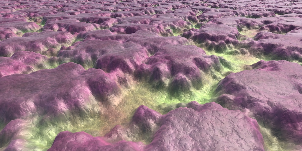
A collection of tutorials that cover how to write your own shaders in Unity.
Thanks, will check that!
Hi again, I have another question, does someone knows why I have this weird transparency effect ? (The transparent object behind the door is visible even where the door is not transparent (the wood part)) I have set both materials to surface type "Transparent" (I am using URP) Thanks !
@spring lagoon the door's material is also set to transparent?
Yes, but this is mandatory no ? Because else I have black squares between the wood
check the depth buffer, it doesn't know how to sort objects
and can't you make theobject opaque?
and then use alpha cutoff
idk tbh
Was about to mention that
Omg you're right, I'm so stupid 😭 I set back the materials to opaque and then activated the "Alpha Clipping" checkbox and it's working... x)
alpha cutoff just discards pixels based on alpha right? but the object can still be opaque so it will draw to the depth buffer and then unity knows how to sort pixels
Correct.
Thanks you so much 🙂
Though even with transparency it usually doesn't have this bad of a sorting issue. Unless it's all a part of the same model?
Or perhaps the render queue was changed
Thanks you so much 🙂
@spring lagoon good luck with minecraft 2, seems like a fun project
The door and the grass behind are two separates objects
Yeah I am just having fun with a minecraft mesh exporter, and it's kinda fun x)
Is the origin of the mesh actually where it's placed though?
Aka pivot of the object
I'd assume the sorting issue is because the pivot of the grass object is closer to the camera than the door's pivot
Their pivot points are not on the same point, and yes I think the grass pivot is closer to the camera than the door one
Yeah, that would be the problem then. Using opaque + cutout fixes it though since it uses the depth buffer to sort things correctly. If you needed transparent, you'd likely have to split the meshes up
Yes I'll stick with Alpha Clipping, it's working nicely 🙂 (Thanks again :3)
How do you acccess texture offset properties with HDRP layered lit shader?
I tried renderer.material.SetTextureOffset("_BaseColorMap", new Vector2(1f, 1f));
I think you can offset the "Tiling" and "Offset" by appending _ST to the texture reference.
_BaseColor0
See the property names here : https://github.com/Unity-Technologies/Graphics/blob/master/com.unity.render-pipelines.high-definition/Runtime/Material/LayeredLit/LayeredLit.shader

GitHub
Unity Graphics - Including Scriptable Render Pipeline - Unity-Technologies/Graphics
Oh right, SetTextureOffset probably already handles that. I think you mean _BaseColorMap0 though
Have you tested it with values other than Vector2(1,1)? As an offset of 1 is the full texture. With a tiling texture you won't be able to notice a difference
true
Oh, actually I was trying to call the function on MeshRenderer and not Renderer. But now it says that texture property does not exist
heya, i was wondering if surface shaders support texture2D objects, since, well
i kinda reached the sampler limit
and wanted to utilize samplerstates and textures2ds
-i cannot use the macros for texture sampling, since i need to input derivatives
and there is no macro that supports derivatives
Oh. So it does work with a HDRP/Lit material
@digital vector Might be interested in this post : https://forum.unity.com/threads/sampler-count-limit-for-pixel-shader-in-shader-model-5-0.452957/#post-2935641
but I just noticed that my HDRP/Lit shader Failed to compile
-as i mentioned, i need to input derivatives (because of parallax occlusion mapping), and these macros dont support it
tex2D(_MainTex, uv, dx, dy)
something like this
the only way I can make new materials with HDRP/Lit shader is by duplicating old ones in the explorer lol
@digital vector Miiight be able to use _Texture.SampleGrad(sampler_Texture, uv, dx, dy), though it would only be supported in shader model 4.
wouldnt that need texture2Ds?
Oh I guess :\
because my problem was that unity doesnt recognize Texture2D in the first place :'D
Does unity_AmbientSky not work in URP? I can't figure out how to sample ambient/environment light in an unlit URP shader for the life of me.
I'm using ASE and outputting the ambient sky color directly to test, but it's black.
@tardy spire The Ambient Node seems to use :
float3 _Ambient_Equator = SHADERGRAPH_AMBIENT_EQUATOR;
float3 _Ambient_Ground = SHADERGRAPH_AMBIENT_GROUND;```Ah, but that's just a macro for unity_AmbientSky
i read somewhere that the branch node (shadergraph) calculates both the true and false states - is that true?
i thought you could use a branch to add toggleable optimizations
@tardy spire I also can't seem to get it working. I also came across a changelog for URP v10.0.0 which mentions this though : Fixed issue that caused unity_AmbientSky, unity_AmbientEquator and unity_AmbientGround variables to be unintialized., so it's possible it's just bugged in older versions.
@regal stag thanks for checking, I'll see if I can update URP and hopefully that will fix it!
Might need to use a C# script to set it, something like Shader.SetGlobalColor("unity_AmbientSky", RenderSettings.ambientSkyColor); maybe
@rustic zinc my understanding is that you should assume the GPU will do both
use shaderfeature/multicompile if you want to be certain a shader only runs certain parts based on bools/enums
@fossil torrent That was me.
DDX and DDY are the X and Y screen space derivatives of the fragment shader.
They give you the variation on X and Y of a given variable.
In short : plug a variable to DDX, and the output of the node is how much this variable changes between this pixel and the pixel just on the left or right.If you input the scenedepth into DDX and DDY, you'll be able to actually calculate the normal of the pixels behind your water surface, in screen space.
Transform this into world space, and by projecting it on the plane, you should be able to get the vectors you've showedI know it can sound a bit cryptic and not easy. Try to do something with those hints, and come back if you struggle to much 🙂
@amber saffron Wow I'll try this tomorrow, thank for the explanation 😄
does anyone here have experience generating a mesh at runtime using compute shaders?
if not, does anyone know where I could find information about that?
@nimble cloud check out Sebastian Lague on YT with his planets video
I tried doing a laser tutorial, but I can't find any "Laser shaders", what am I supposed to do?
which video is that? is that his more recent coding adventures one, because he doesn't go into a lot of detail about it.
also, really any stuff on compute shaders would help - I followed a guide he recommended earlier in the series (the one about raytracing) but I still feel like I have a lot to work on to really 'get' it entirely
@nimble cloud "Unity Shade Graph - Laser Beam Tutorial" is the video
OMG the shader book is so difficult 😦
Is there a way to make a shader unlisted in the dialogue/list you get when choosing a shader for a material? I have something I use internally for post processing and never for objects, it's kind of irritating to have it always pop up in the list
@teal breach maybe put it under 'hidden'?
So like the shader name on top of the file
"Hidden/PostFX/MyEffect"
Yup in the blackboard
On the top
Where it says 'Shader Graphs'
That field is editable
ahh awesome
the light grey made me completely miss it! I looked everywhere else
in the master, along the ribbon...
Same for subgraphs! You can edit where they show up in the node window
That's very handy
Yeah indeed, shadergraph could use some UX/UI improvements though, not all of these things are very clear
Just to double-check my understanding - I think that if I use these settings, the resulting normal vectors are already in tangent space (so I don't need to blend normals with the underlying model). Is that correct?
How do I make a shader that has a intersect that isn't perpendicular, but rather parallel, to the plane it is intersecting?
do you have a picture? I find it hard to visualise that
So instead of have the bright yellow intersect that rises parallel to the ground, i want the entire circular area to be affected instead
ahh sure, ok, the circular area on the floor?
will this only be applied to spherical volumes?
if so, I expect you could sample the depth buffer to get the distance from camera of a pixel when drawn, then transform that to get the world space position of the pixel you are drawing over. Compare this to the world space position of the spherical volume to determine whether you are inside the sphere (make it yellow) or outside (leave as it is)
lol wow thats definitely way over my head!
I barely stumbled through creating the intersect lol
Can it only be done with Spheres?
If you use Shadergraph there are a lot of tutorials that can give you an idea how to do that. Often can find simple ways to accomplishing somethings that looks complicated.
I have a forcefield tutorial which basically does exactly what Elliot suggested. It has various other effects such as distortion ontop of it too, but should help. https://cyangamedev.wordpress.com/2019/09/04/forcefield-shader-breakdown/
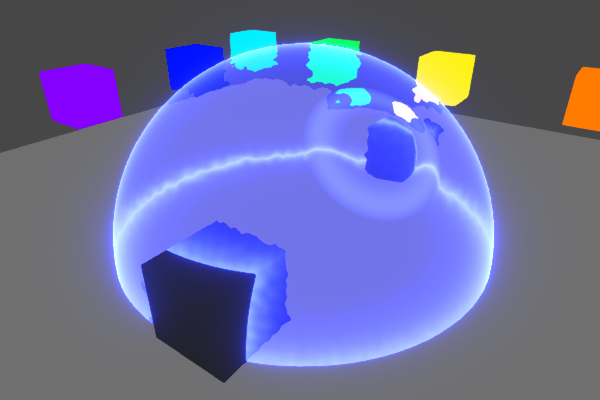
Intro This post is a more advanced version of the Simple Forcefield Breakdown. You don’t have to read that one first, but it might help with understanding this one further. This shader uses a Fresn…
Since it is reliant on the distance from a point, it will only work for a sphere. You might be able to apply a similar concept to other signed distance functions though
wow thanks very much. you both gave a great point to start from!
Can it only be done with Spheres?
@dire delta
IDK what you want....a "flat" circle on the ground, or a glowing "circle" with height.
If flat, you can just put a quad on the ground a tad above ground level, with a circle on it, computed or not.
If "glowing upward" you can use the sphere, but clip above a certain height. Or a cylinder for that matter.
Does anyone have any insight how I might go about interpreting noise (or any texture I suppose) as tessellated triangles via shadergraph?
Um, What? Tessellation sub-divides triangles. But you still get your UV's out of it to read a noise/texture with. Would be set from your original triangle UV's but sub-divided.
Shader graph doesn't have any tessellation support yet afaik
I'm not sure what they're even asking.
Do you want to procedurally generate triangles, by reading a texture or something?
say you wanted to apply a pixelate effect on an image that would be what I'm asking for but with tessellated squares
I believe cyan is right
You can move the vertices of a mesh, but you can't add extra geometry atm
If you mean GPU tessellation, sure, he's right.
But you can produce a pixel effect with SG.
(manual tessellation)
And there's procedural draw calls on the C# side, if you know how many verts you want.
But I have no idea what you're really asking, like for real.
If it's GPU tessellation, just read your noise or whatever texture as normal and "pretend" it's tessellated. Later, SG will support further tessellation, but for now just use a more tessellated mesh or a procedural call. You still get UV's, like always. I mean, there were days when GPU's didn't support tessellation, and everyone coded back and forth to school uphill both ways....
I believe the Boat Attack demo has an example of c# job based tessellation for the water system.
I need to look closer at that myself as it would be nice to add that to my water for a little more detail. It's very performant, probably a good starting point
@dire delta
IDK what you want....a "flat" circle on the ground, or a glowing "circle" with height.
If flat, you can just put a quad on the ground a tad above ground level, with a circle on it, computed or not.
If "glowing upward" you can use the sphere, but clip above a certain height. Or a cylinder for that matter.
@meager pelican actually I’m looking for it to be almost like a projection. A quad won’t work because it would just clip any elevation. I need something that would be seen on any elevation
You mean a decal?
@grand jolt

A specular highlight is the bright spot of light that appears on shiny objects when illuminated (for example, see image on right). Specular highlights are important in 3D computer graphics, as they provide a strong visual cue for the shape of an object and its location with r...
You can use something like the blinn Phong model
And code that in
Basically NdotL
Where N is normal vector
L is light direction
I tried getting the MainLight direction with a custom function node:
#if SHADERGRAPH_PREVIEW
    Direction = half3(0.5, 0.5, 0);
    Color = 1;
#else
    Light light = GetMainLight();
    Direction = light.direction;
    Color = light.color;
#endif
based on this blog post: https://blogs.unity3d.com/2019/07/31/custom-lighting-in-shader-graph-expanding-your-graphs-in-2019/
Now I am using HDRP and I am getting "unrecognized identifier 'Light'" and I got no clue where to go from here
That method only works in LWRP/URP. I don't think there's a way to get the light direction in HDRP, other than passing it in from a C# script. Setting a global shader variable is probably the easiest way.
Well that's awkward... I just switched to HDRP from URP because I wanted to recreate a zelda toon shader in shadergraph and I needed an unlit master node with emission but thanks for the headup @regal stag !
Not really sure why emission would be needed for a toon shader
trying to recreate this: https://roystan.net/articles/toon-shader.html but for URP/HDRP
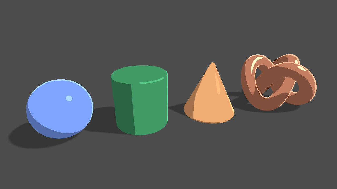
Learn to write a toon shader for Unity engine with specular reflections, rim lighting and shadow casting.
thought I might just use shadergraph but well...
I'm not really sure how this works, but is it possible to sample the shadowmap in urp to modify how the shadows are applied a bit? I'm working on a simplified lighting model where surface angle doesn't affect lighting - the surface is either completely lit or completely in shadow. This is what it looks like with standard attenuation. I'd like to add a fade to the shadow to make the surface look soft and subsurfacey. Is this possible?
@prime timber Right, but you could just use the Unlit master node's Color input for that?
(Here's the look I'm shooting for with a fade)
@regal stag Probably should've done that.. still kinda frustrating and disappointed in shadergraph. It seems lackluster and unfinished.
i was wondering: i have a surface shader, which has two additional passes to generate grass on top of it; can i somehow pass the vertex function i defined in the surface shader on to the single passes?
because, when trying to replicate the vertex function in the vertex shader, it has some kinda offset for _Time
nvm, i realized i put it in the tesselation vertex function, not the vertex function :'D
I have a problem where my leave shader looks a bit odd. it seems that, when you look at something thats transparent, it does not render the leaves behing it. how do i fix this
should probably use clipping instead of blending
Using shader graph, is there a way to get the scene colour after the transparency pass?
I want to make a 'warping' effect
so I assumed, scene colour -> offset UVs
but the scene color node only picks up opaque objects
and all sprites are translucent by default right?
@regal stag you saved me https://twitter.com/cyanilux/status/1169932943869059073

I've never used the Orthographic projection, but depth effects work slightly differently. I was asked about it on the official Unity discord, and after some research got it working, so might as well share a small thread here too. 🙂 #unity3D #shaders https://t.co/ng67JlVsyk
Likes
382
again
@regal stag can confirm, this exact guide was a life saver
@regal stag Do your shader tutorials work for the most part in amplify?
I haven't used amplify, but it should be quite similar to shader graph
While the exact nodes and connections might vary, the concept / maths will still be the same
@full sail The Scene Color only works with opaque. You might be able to move the sprites into a opaque queue but no idea if that would work. If you are using the 2D Renderer I don't think the texture even gets created, though I could be wrong about that / it might have changed.
If you are using URP's Forward Renderer though, you can apply a distortion shader effect on a Blit render feature. The shader would take in the _MainTex rather than relying on scene color.
upon further reading, the answer to my question is no. You can't get the raw frame buffer from the camera
I'm using the forward renderer, I'm not familiar with Blit render feature, I'll do some digging - cheers
@full sail I have a post processing post which goes through it a bit here : https://cyangamedev.wordpress.com/2020/06/22/urp-post-processing/#CustomEffects
you're a star
@regal stag I've got this working - in your opinion, is this appropriate for mobile platforms?
or is it very intensive?
I presume what you're doing is sending the texture from that C script
I think fullscreen effects like this can be quite expensive on mobile
I figured as much
I think due to overdraw reasons, but I'm no expert when it comes to mobile or shader profiling.
Not sure why, but Scene Depth seems to always be returning 0 for my orthographic projection (with material set to transparent)
_CameraDepthAttachment looks fine in the Frame Debug though
Have you got the depth texture enabled (in URP asset / camera override)?
Is the "Post Processing" option on the camera ticked?