#archived-shaders
1 messages · Page 158 of 1
Yes, each pixel is basically a vector. The exact type depends on the textures format, but a 32bit-color RGBA texture is basically an array of float4s.
you can either use a compute shader to write to it, or use the texture Pixel modification APIs
https://docs.unity3d.com/ScriptReference/Texture2D.GetRawTextureData.html
https://docs.unity3d.com/ScriptReference/Texture2D.LoadRawTextureData.html

reading on the texture requires sampling it


Warning!: Import the files first to an empty project to test if they work with your Unity version! Otherwise it could break your project files.
Files for Unity 2019.1.0b3:
https://drive.google.com/file/d/1PmNe4RDnVvupP0JBE_akCA9ZUOddwS-X/view?usp=sharing
Other versions:
1...
How its work?
not familiar with that
how to make particles glow?
@tropic galleon checkout the "boat attack" demo by unity, there is a git for it. included is an example of how to leave wake behind boats or there is a good ocean on store which does it very well too.
How do I even get shadergraph
What is URP and HDRP?
LWRP was renamed to URP
I believe that LWRP is still listed in the package manager so it can still be used to update the package, but a lot of the versions are probably just URP ones
If you dont see universal rp on package manager it means you are on older unity
What is URP and HDRP?
@smoky sigil URP Its Universal Render Pipeline , to use for graphics like mobile, HDRP its High Definition Render Pipeline to create games in PC, Mac etc the two pipelines can to use shader graph
Thanks ^^
uhm
URP is for the Alpha/Beta likely
@smoky sigil Actually I think the name has changed as of 2019.3
Universal render pipeline will become the default pipeline so definitely also for desktop and console
Universal is just 'universal', mobile + desktop + console
HDRP is for higher end platforms like desktop + consoles
packet manager
Yeah, both are included in the package manager. Likely so that users still using lightweight can easily update to the newer versions without having to uninstall and reinstall URP.
I am so done for the day :D
But how do I use a shader I made in graph editor?
Because... That's what I can't do yet :D
If you install URP in 2019.3, shader graph will be included
It
Create > shader > graph to create a new graph
was and I made a shader
Same as using shaders written using code. Apply it to a Material.
but how do I put it ... yeah how do I Apply it to a material?
But how do I use a shader I made in graph editor?
@smoky sigil apply shader to material, apply material to object
just drag the shader onto the material 🙂
You can right click on the shadergraph and click on 'create material' to automatically create a material that uses the shader
Create a material and select the shader from the dropdown, or drag it onto it
I could use some advice too if you guys don't mind
Right click the .shadergraph file in your project window and click 'create material'
@main cypress ask away
@smoky sigil read this whole guide through
you probably need to assign an active render pipeline asset, but the guide explains it all, I recommend giving it a read
It looks like you've created one, but you also need to set it under the project settings
Try clicking Save Asset in Shader Graph
On the top left corner of the shader graph window
@main cypress ask away
@devout quarry I'm wondering how to do something similar to decals in URP, any idea how that could be accomplished?
I'm trying to figure out how I can recreate the sticker functionality from LittleBigPlanet
GitHub
A mesh-based PBR decal system for Unity's universal render pipeline. - Anatta336/driven-decals
this system works well
but this
GitHub
Unity unlit screen space decal shader for URP. Just create a new material using this shader, then assign it to a new unity cube GameObject = DONE, now you have unlit decal working in URP - ColinLeu...
is basically a single shader, and also works very nicely
https://github.com/ColinLeung-NiloCat/UnityURPUnlitScreenSpaceDecalShader
@devout quarry thanks I actually tried this one
GitHub
Unity unlit screen space decal shader for URP. Just create a new material using this shader, then assign it to a new unity cube GameObject = DONE, now you have unlit decal working in URP - ColinLeu...
But I have no idea how it works
I also have no idea whether this is the best solution for what I'm trying to do
I actually don't know much about shaders which is why I'm so lost
Also not even sure shaders are the best way to do it. Is there a way of painting on a texture in-game?
I think the NiloCat shader should help you out
hold on
check this video

Pikmin is a game where you command an army of these tiny creatures that help you on your journey by carrying objects back to your ship and fighting a variety of dangerous enemies. In this video, I show how I tried to do a simple recreation of the basic gameplay of managing the...
he uses the decal shader to project the texture onto the geometry
so you can use it to put a texture nicely on the surroundings
like a sticker
actually yeah the way that he does it is pretty useful actually
there's also this
but I recommend taking a look at the nilocat shader first, because you see it in action in the video, and it's really just 1 shader
and you can download the project from in the video if you need to see how it was set up
Yeah I've come across all these I've even used the nilocat one
but I'm not sure if it's the actual best way to do what I want to do
but thanks that was helpful
the driven decals system is more feature rich
but works the same as you can see, this would be like a sticker right?
yeah it would work, but I'm wondering what would happen if there were a lot of those in a scene, would it affect performance?
and I'm also just wondering how that shader works
because I have no idea
the driven decal system is really just a quad
I'm not sure either, never looked at it
the driven decals system uses a shadergraph shader btw
so maybe cool to look at
oh right
I'll have a look, thanks
I'll experiment a little bit and show you what I come up with 🙂 thanks for the help
trying to make a Toon Shader for a fighting game using Shader Graph. I can make the lighting effect, but I am having trouble with the actual outline part
and I can't figure out how to make it in shader graph
@quick wigeon problem is that the shadergraph does not allow for multipass shaders taht are normaly used to make a inverted coppy of the mesh and make that extured out.
oh
here's a tutorial i came across that doesnt use shader graph i think
Learn to write an outline edge detection shader for Unity engine, integrated with the post-processing stack. This effect is especially popular as a compliment to toon shading, or in CAD and architectural rendering.
perhaps the ideas u can use tho?
Anyone know how to make a cube half way invisible? Like at the top of the cube its a solid color but as it goes down it becomes invisible?
hi guys i want make a cube glow something like this. Is there any simple method to achieve this if I am not using LWRP/HDRP?
thanks
Hi, I'm fairly new to unity, can someone help/tell me what I'm doing wrong? I'm just trying to change the hue of my texture but I can't for the life of me figure out why the output is just black+white
Your type should not be a Normal Map
oh yeah I was messing around, default doesn't work either
but also, if you offset grey you still get grey, if something has no hue in the first place then how do you offset it
oh it originally has a color, looks like this
you're combining the red channel
so it's R,R,R
Documentation
Shader Graph: https://docs.unity3d.com/Packages/com.unity.shadergraph@latest
Forums
Shader Graph: https://forum.unity.com/forums/shader-graph.346/
Shaders: https://forum.unity.com/forums/shaders.16/
RenderDoc
https://renderdoc.org/
https://docs.unity3d.com/Manual/RenderDocIntegration.html
Roadmap
Shadergraph: https://portal.productboard.com/8ufdwj59ehtmsvxenjumxo82/tabs/7-shader-graph
Shader System: https://portal.productboard.com/8ufdwj59ehtmsvxenjumxo82/tabs/125-shader-system
Okay guys
The next step is Fresnel effect, but I need to be able to adjust it's strength with Code and even turn it off.
If anyone can help me with that I'll be berry happy
In shadergraph you can add a property in the blackboard that controls the power of the fresnel effect
you can give that property a 'reference' that you can then use in your C# script
using Material.SetFloat
so for example material.SetFloat("_FresnelPower", 5);
Thanks, but how do I
you can give that property a 'reference' that you can then use in your C# script
look at the blackboard
there is a reference field there
"Reference name"
just use like "_FresnelPower"
Hmm, I've read a tutorial on how complicated it would be because in earlier versions they had no proper reference names...
And I am still confused but thank you I'll try to figure it out ^^
You're using shadergraph right?
Really, in the blackboard for the property you want to change by script, add a reference name
Then, you can use that reference name in your C# script
in the blackboard
Where.
Sorry, I am just confused ^^
Vector1 is a float
so... IDK as I said, I am confused ^^
vector1 = float
So
My first bigger issue, I don't know how to solve. If my game gets started with a white skybox instead of a black one I get this bug
This is how it should be btw
Are you using a lit or unlit master node?
In shader graph, the 'final' node
Says either 'unlit' or 'pbr' I think
Try using an unlit node
Create new master node that's unlit, then right click on it and click 'set active', then you can remove the old master node
Alright, but I use emission for the fern effect. Hmm, brb I have to try it out
Yeah, I don't get the effect I had befor
I use emission for the Fernsel
You can take a look at the Video I posted before.
Ugh, first function and I already have a huge problem 😅
But...
I am confused
even so, I don't get this bug every time I run my code
Uh yeah not sure, but then for your pbr node you'll need to make sure it's not affected by the skybox lighting
My problem is if it "Generates lighting" with a white skybox
Rather than a skybox it might be better to have the camera set to a solid colour background type
Can I just generate lighting with a line of code?
Because then in the start function I set the Sky Black, re-generate it, and then it's all good
Like with the "generate lighting" button in the settings
Hmm
Alright this gets me to many more questions
If I generate lighting at the start of the game, will characters spawned afterwards generate their lighting in the current skybox?
I'm not too sure how the environmental/ambient lighting works, but you might be able to set it to colour, rather than using the skybox.
(Lighting window/tab btw)
Or, as I suggested a bit above. Rather than using a skybox, leave it at black and change the camera to render a background colour rather than a skybox. That background colour shouldn't affect lighting.
Also, you can still use the fresnel output for an Unlit master node, which may be preferred if you aren't actually using lighting. The emission output on the PBR is basically like an "unlit" overlay over the lit result. For the unlit node, it's already unlit so you can combine the texture and fresnel results (e.g. using an add or maximum node), and put that into the colour input on the unlit master.
I am
So confused
Like... I can not recreate this bug anymore???
But whatever I guess...
Now, How do I add just a colored filter on top of everything. Like in shooters, when you get hurt, the way the screen turns red.
Is there any method to put shaders on top of everything? Maybe even Post processing?
Aye
I fixed it by setting "Enviroment reflections" to custom and not adding any cubemap
But Is there any method to put shaders on top of everything? Maybe even Post processing?
There are probably ways to tint the screen using URP's post processing, although it doesn't support apply custom shaders (yet?).
You can apply shaders to the screen using a custom renderer feature for the Forward Renderer, using something like the Blit.cs and BlitPass.cs here : https://github.com/Unity-Technologies/UniversalRenderingExamples/tree/master/Assets/Scripts/Runtime/RenderPasses
(and those shaders need to pass _MainTex for the camera's texture, which you can then edit and pass out in an unlit shader)
Now my next steps are:
- Make a shader for bossfights. The bosses should light up their environment.
- Make a shader for the Blood rain event.
- Make the shaders universal, Applying to all NPC/Enviromental Objects.
- Done.
But how I'll do that? Good question.
hmmm
would adding a custom renderer feature allow me to re-shade all objects in my scene that go "underwater"
to mean that the albedo takes into account their distance from the light and falloffs faster (cos underwater it shoul go blue then black a lot more than in air)
What if I want to add a 2D scene on top of the 3D?
Like... what would be great for shaders, and the UI
But how do I do that...
._.
@marsh turret you could work with a post processing volume?
position it under the water surface and tint the scene blue
it's an approximation for sure, but could look convincing enough
Why...
This time we will talk about the new post processing layer that will supersede the post processing stack in the near future. I will tell you how you can use different profiles in your scene and how you can upgrade to the new post processing flawless.
Does this not work? or am I stupid? or is it old?
Urp uses post processing v3
Gameobject>create>volume
Then you can add post processing
position it under the water surface and tint the scene blue
@devout quarry issue there is players IN the water looking down
water needs to get darker as you look down...sunlight needs to drop off....ideally all lights but sunlight esp.
Urp uses post processing v3
Gameobject>create>volume
Then you can add post processing
Okay
i'm already doing PP for color tint, and I've coded in for fog to get stronger and darker as you descend
How do I activate it/add it to the game?
@marsh turret but if players stand in the water, so they have their eyes above the water line right? and they look down?
They see the water surfaces right? So the objects will have whatever tint your water shader has
I'm not sure I understand
I think they want a gradient so objects deeper are darker than objects nearer the surface. You could do something like that by using the world space Y position.
On the objects shader. This assumes the water is at a constant height throughout the map though too.
Yeah
Or multiple post process volumes stacked on eachother and blend between them?
and why do I keep trying to get my simplistic but hard to make visual style ._.
@smoky sigil have you enabled post processing on your camera?
No, how do I do that...
aaah, i understand what you meant @devout quarry
sorry, I should have been more specific
Sorry that I'm annoying, but I am really trying...
my game is not water like a pool, but water like the ocean
so if a player is swimming underwater (or more often, in their submarine, and the camera is following them)
then when they look down, the water should be getting darker and darker as it's deeper
Ah right yeah I think cyan's solution would be good
In the shader of the underwater objects, take world position into account and color based on that
Look at the camera component. There should be a "Post Processing" checkbox. Just make sure that's checked
I swear to god I was googling like crazy and went trough the list 3 times
Didn't see it
._.
hmmm my issue ther is what about objects that move from in water to out of water?
do I just need to add the shader code to every single object in my scene that might go underwater?
that would be...unfortunate
i was hoping there would be some way to "override" the lighting on any surface based on if it's underwater or not
(I can find out if any particular point is underwater or not ,that's not an issue)
also it needs to take into account whether the light source is above water or not...if it's above water (ie. the main Directional) then falloff needs to be measured based on that point's distance to the water surface...
otherwise, it needs to calculate falloff from the light (say, an underwater spotlight) and attenuate it properly
Ugh
if that's gonna be too much work, I'd settle for just the main directional light
How do I reference the RGB Tint in a script?
i'm seeing some stuff here about a custom shader node that can reference the main light https://gist.github.com/bitinn/72922a0a69f6d723d94e94f2fc21230e

Gist
A custom node for Unity's ShaderGraph to capture lighting and use it into the shader. Works as of Dec 2018, but the APIs might change! - MainLightDataNode.cs
but that still means adding a shader node and override to every single object...
just wish there was a way to simply change teh lighting model so "if surface is below (waterlevel), attenuate light using this formula"
CodeFunctionNode is dated and not supported anymore. There's custom function nodes in shadergraph instead. https://blogs.unity3d.com/2019/07/31/custom-lighting-in-shader-graph-expanding-your-graphs-in-2019/
gotchya ta
@marsh turret have you looked at the Crest project, it covers a lot of what you are asking. Git version for standard renderer is free, so you can check it out and if you need URP/HDRP can buy on asset store.
yeah I've seen Crest - sadly this is a commercial project and previous..experience has led me and other members to be very disinclined to touch assets
(which is to say "oh look, they updated something. And our game is broke and unlikely to ever be able to be updated ever again. Yay")
on top of that it's a bit overkill - graphical fidelity would be very costly at that level, this is a physics game so lots going on already
some asset devs do abandon work so it can becomre outdated, but the crest guys are keeping it updated and actively deceloping it. They are very helpful, I know it's easy to get stung by assets. But it's also easy to design you game to be modular and flexible to swap in assets or out.
but thank you for the suggestion - I might reach out to then if they have any tips
crest is Very performant and can be adjusted / customised to any graphic style, you should pop onto their discord and see who's using it and what problems are (if any)
there is also a good list of water papers on their site for reference material
How the hell do I access PostProcessing-Variables in 2019.3 URP
hmmmm
could I write a custom renderer in URP
that goes over what the opaque and transparent passes have already done
and say "hey if underwater, darken the albedo based on "this""?
how do custom renderers work in terms of overlaying?
@marsh turret might want to disect this repo, this is on built in renderer though

GitHub
A Unity port of Martins Upitis' fantastic ocean water shader, which was originally coded in GLSL for Blender. - muckSponge/Optically-Realistic-Water
oh forgot the link my bad
ta
hey Cyan, are you around?
Yea
sorry to bother you
you wrote this right?
Intro This post includes two examples to produce fog shader effects. In both cases, the shader is applied to a flat plane or quad where the alpha of the surface is altered based on depth values to …
Yep
it's a bit of a smelly hack
but do you think if I create a plane in my water
(like say -20)
and move it based on the position of the camera
i could "fake" the underwater falloff/darkness effect I'm looking for
(i basically need a volumetric fog but URP hasn't got one, and certainly not one that's very performant)
it's that or I'm gonna have to add a node to every single shader in my game that checks if it's underwater then adjusts it's albedo based on distance to water surface/directional light...
Hmm, that definitely seems a bit hackish and Idk if it'll give the result you want
i am struggling to find an approach that will tbh
It might be possible to apply a similar effect as post processing instead, that way you wouldn't have to worry about moving the plane
in URP?
i thouht about a custom renderer
but it would be layer-based and I can't very well change an object's layers based on if it's out of water or in
i am using built-in fog and making it darker etc as player descends
but...
it's a 2d effect
(i'm a 3d artist, not a very good graphicsprogrammer so I might be using art teminology not programmer language, sorry)
so it's rendered over the camera view...
not a true 3d effect..
so if the player looks down, it isn't "visible" as a flat effect looking down into the water
I'm thinking that a post processing effect that reconstructs the world position from the depth texture might work. Then tint darker based on the Y axis.
can URP have custom PP effects?
I've done something similar for non-image effects, but the method I used won't work. I think this might help though : https://github.com/keijiro/DepthInverseProjection
GitHub
An example showing how to inverse-project depth samples into the view/world space in Unity. - keijiro/DepthInverseProjection
hmmm, a PP could work nicely if achievable
URP's integrated post processing doesn't, but you can apply a shader via a Blit using a custom render feature. See Blit and BlitPass here : https://github.com/Unity-Technologies/UniversalRenderingExamples/tree/master/Assets/Scripts/Runtime/RenderPasses
does that mean subsituting the shader into everything being rendereed?
or am I mixing stuff up?
Nah, the RenderObjects feature uses an overrideMaterial to replace the shader being rendered
ah so I don't lose colors, textures etc
A Blit feature just takes what the camera renders into a _MainTex property, which you can then edit and pass out
that's what I need 🙂
thank you Cyan
i proabbly won't get it working, cos this is my first real foray into serious programming...ten years of 3D in the industry etc but first time really doing actual code stuff
but I at least know where to look. Thank you.
Good luck 👍
that depth-inverse projection should be the key..I can use that code to get the y position, then modulate the albedo darkness from that
be nice if I could just do that in the shader graph mind you lol. I like node-editing - we've used that in 3D for years now!
actually...i..can?
if Blit just allows you to take the _MainTex...
Might be able to rewrite it in node form, or use a custom function node
i can make a shader in shader-graph that uses the _MainTex value, does the light-position stuff in the shader graph...
i think
Hmm, noticing that the DepthInverseProjection is using BlitFullscreenTriangle rather than a regular blit. I think it's written for the PPv2 stack so Idk it'll probably need tweaking.
The InverseProjection shader also uses the SV_VertexID, which I don't think is accessible in shadergraph
It's only using it for the clip space position though, maybe there's another way to get that
Hmm
Im fiddling around with pixel accurate picking
using a replacement shader, packing data into Color32, etc.
im having problems with linear color space, which is what i assume i should use
i create the render texture like this: new RenderTexture(w, h, 24, RenderTextureFormat.ARGB32, RenderTextureReadWrite.Linear);
so when i 'inject' the data from unity/C# side, this is what i get: id: 64190, as 32bit color: RGBA(190, 250, 0, 0)
but when i pull it out of the texture, this is what i get: id: 62595, as 32bit color: RGBA(131, 244, 0, 0)
it's... off
this is what RenderTextureReadWrite.Linear says in intellisense
so i would assume that this DOESNT convert the colors, right
the integer ID is converted to a Color32 like this
    unsafe static Color32 IdEncode(int id)
    {
        return *(Color32*)&id;
    }
and then assigned on a MaterialPropertyBlock like this: block.SetColor(PROPERTY, idEncoded);
now i noticed that SetColor converts Color32 to a Color
but that conversion seems harmless (it's just channel/(float)byte.Maxvalue which is fine)
here is the weird thing tho
if i create the texture with RenderTextureReadWrite.sRGB instead, it... WORKS.
It produces the right id when the color data in the render texture is converted to a an int again...
but of course... sRGB mode says this
which seems like it's the OPPOSITE of what i want...
so where the hell is the color getting fucked up?
I am at a damn loss
hmmm, i am not sure i know enough about shadergraph/prgroamming to achieve this
i'm fairly sure I can do a shader in shadre-graph that would take the world-position of a vertex and get the light level effect working on it based on it's -y coord
To make it EVEN more confusing, if i switch to using a float, and using RFloat as color format
and convert the ints to floats, and then back also
but i'm not sure if I can do the same to a shader which is being rendered in a blit pass
it works... NO MATTER what the color format is being used
well i got it fkn working, in both sRGB and Linear mode finally
fkn hell that was way more work than i thought it'd be because of the damn color format
oh ho! Cyan:

GitHub
This project contains a collection of Custom Renderer examples. This will be updated as we refine the feature and add more options. - Unity-Technologies/UniversalRenderingExamples
they added a new "example", making a gradient-based distance fog
Oh cool, didn't see that branch. It'll probably be similar effect to the fog though, where it won't vary with the depth of the water.
it's a bit "hidden"
no, but I an change that
it's a depth-based fog effect - so all I need to do is tie the "depth" in question to a world position insted of the camera
and that's all being done in the shder graph
Hmm, but it's still an image effect / blit. It's a similar problem that the depth inverse projection thing was trying to solve
arggghhhh you've got to be shitting me
it's not there
the wiki for it has the effect listed, but the GIT code is missing entirely 😦
It is there, it's just on a separate branch for some reason. https://github.com/Unity-Technologies/UniversalRenderingExamples/tree/gradient-fog
aaah yeah
thank you
i mean, if I'm reading this properly tho
it should do everything I'm looking for; I can change the albedo of the objects I want to change, based on their position relative to the water surface
becasue it's not dependent on the camera position inherently - it's getting a depth texture for the positions...
instead I can use a worldposition
yeah, OK, I've just seen why I was wrong.
because it's an image effect, it's only gonna work for overlaying the image effectively..
that said..
Lol.. why is there even a UNITY_MATRIX_I_P, if it's not even defined in URP. 🙃
#define UNITY_MATRIX_I_P ERROR_UNITY_MATRIX_I_P_IS_NOT_DEFINED
if I have a render pass for the Directional light....which does something like this...then a second render pass that explicitly does NOT render the directional light but does render other lights...or something like that
or maybe...since I know what the directional light is always doing, calculate what the effect of the directional light on each vertex position is, then discount the correct amount based on what it should be since we're underwater..
Anyone know a good tutorial on a shader that pulses emission as well as changing the color?
@grand jolt pulsing can be done using sin + _Time.y variable
changing color can be done the same way with lerp + _Time.y
float strength = lerp(StrengthMin, StrengthMax, sin(_Time.y * 10) * 0.5 + 0.5);
float4 color = lerp(ColorMin, ColorMax, sin(_Time.y * 10) * 0.5 + 0.5);
@orchid briar aha, thanks, at least I know what nodes to use (I'm using Shader Graph, should have clarified that sorry), do you know of any videos where someone does it in graph? I like to see it visually as i'm new to Shader Graph and tend to mess things up if I do it solo 😛
sorry no clue dont use shader graph
yeah theres literally a sin and lerp node in it so i'll give them a look
thanks anyways
np
@grand jolt the time node should also have a sin output
@devout quarry yeah found it, just going to fiddle with things until it works, would rather use a shader than coding, waaaay more performant 😛
@devout quarry yeah, plus SG tends to do things is a more compact way, it streamlines the code if possible, I believe
I think the opposite is true
It would make sense that shader graph introduces overhead and hand-written shaders are more performant
probably, I may be confusing it when compared to VFX actually
Ah right, VFX graph is very powerful
never used it, but I've seen some results and it's crazy
I have a bunch of mesh effects, but boy if they spawn more than 4 or 5 effects at once my PC goes "BUH..."
I saw the brackeys one where he made like a million particles, that was craaazy
@marsh turret Have been playing around with the world position reconstruction from depth for the blit feature, finally got it working correctly in shadergraph.
I still don't understand exactly how it works, but it does.
Unity hackweek is coming up and I was thinking it might be nice to have a website where one could browse shaders & graphs
what do y'all think?
@lavish sierra
this is already pretty nice
not sure if you had something similar in mind
@devout quarry I'm thinking something more along the lines of https://www.shadertoy.com/
you should publish this up
so with a visual preview
yes, or rather, the visual preview is the main point
hmm, you could, but you're still missing the point
yeah, would be nice to see the effect in action
the "gallery" effect is the main point - it's definitely helpful to download/upload things though
I would link the TIGSource image crawler to demonstrate but looks like that died
is it like this?
never heard of TIG source image crawler, but this is a gallery style thing
yeah, it's like that but it's an automated crawler so a bit less organized
@marsh turret Yeah, it's basically what the Position node (world space) would do for objects in the scene, but as an image effect.
whre exactly did you put your c#
in the Create()?
(i'm trying to duplicate to see if I can do something similar...
I put it in the Blit pass Execute function
It would probably also work in a separate component in the scene or something too.
It's just something that needs to be updated each frame
I haven't done custom renderer before so I was looking at the Blit.cs example code
Yeah, there's a Blit.cs and a BlitPass.cs, you can basically copy them into your project and they should just work.
i figured your code was in the AddRenderPasses() method
then realised i was looking at the wrong class
It would probably work there too, as I think that runs per frame each time the feature is used
you should definitely write this up tho
@devout quarry yes, thanks to the time limitations of hackweek you'd probably have to upload from the editor
this is a whole new way to use the SRP for render stuff
so the webgl compilation can happen therein
@marsh turret Yeah I might write it up. It's likely more expensive than just using the Position.y in every shader in the scene, but it is certainly easier if you have a lot of shaders that you'd need to edit.
in my example (which I get is quite niche)
i only call the PP stack for "underwater", cos I can fake depth in the water shader if I'm above teh water
but this (should if I can work out how to make ti work nicely) allow for things like the ground fog effect you have up
to be ran as a post-process
Yea
if you achieve that you should let Unity know, they could add it into the engine as an option
on the fog volume
perhaps
so "fake" volumetrics
not as computationally cheap perhaps
but still usable on mobile etc
still be issues around view angle and stuff I think
but getting the world position in a PP shader is huge
cos you can pass in other stuff like camera position, position of objects etc (e.g my water surface level)
can a shader change an object’s collider? for the ship to react to the waves
i don't think so
but way I have gotten it is I have wave generator code that is lodged into my bouyancy script
(i say mine, I adapted it from a tutorial on water physics!)
that generates the waves and spits out vertexes for the surface etc
i then feed that data into the shader to have the shader render the surface in the right place
but equally the boyouncy script can also use it to determine physics of boats etc
so a big wave can "hit" and make a boat go up...making the wave capsize the boat etc would be for your physics scipts
How you take hit from shader?
cyan: sorry to bother you again (cos I hate people that do that)
but any idea what I've done wron ghere?
I can see the effect working but it's also rendering a big black square covering most of my view
Mmm
I think that's because of the depthonly/shadow caster pass messing with it. I think on the Blit feature there's a pass index that I had set to 0
aaaaah thank you
I was struggling with shader gaph wondering if I'd messed up
yaaay it works
i can go eat now hahah
wife was screaming at me to get dinner
im having a fun problem
...
AsyncGPUReadback.RequestIntoNativeArray()
segfaults the editor
... sigh
can i get the result of the shader?
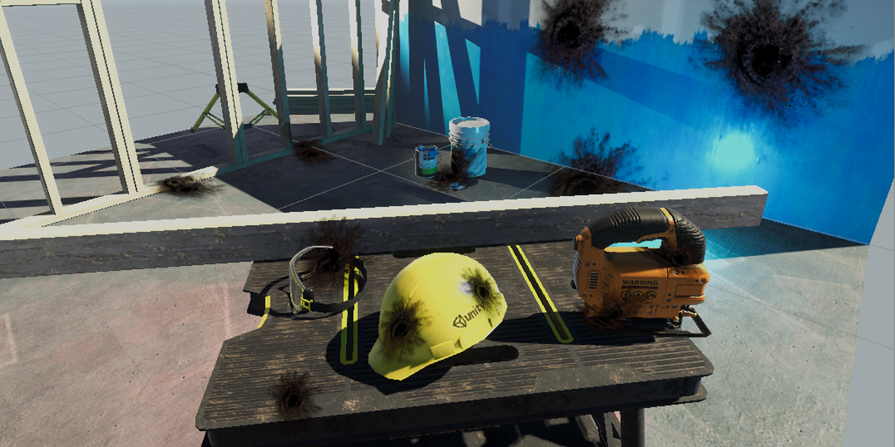
To work in logic
For example, I want to make walls like in rainbow six
@tropic galleon If your referring to blasting walls apart, thats usually achieved by having a duplicate of the wall but with a mesh thats cut into pieces, when someone does enough damage it disables the original wall, enables the breakable one and adds force in the opposite direction to fling the pieces accordingly.
But i'm not sure if they do it that way specifically in R6, or if they use some other method, also not aware of any way to make a shader effect logic like that, but i'm not an expert in shaders so someone else may be able to clarify.
Anyone know why this grid isnt animating? i'm trying to have individual control over which axis animates, i've tested both the outputs of the Vector2's straight into the offset on the tiling node and they both work, so it's something between the Vector2's and the offset input thats not working...
I take it multiply is the correct node for merging them?
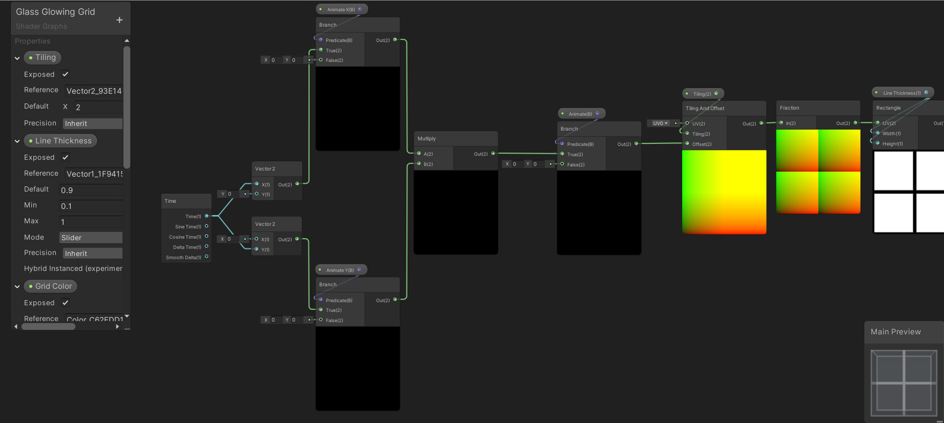
@grand jolt multiplying by zero will get you a zero
since one or the other input in your multiply is always a zero, the output will always be zero too
assuming you toggle between animating X or Y and aren't doing a diagonal (though even in that case only 1/4 scenarios work as intended)
@grand jolt https://steamuserimages-a.akamaihd.net/ugc/929298615334463366/DFF1D4A1BD89DCA29BB6C9CB511AAF05EAB37803/ like this

I think there is some kind of mechanism for generating new walls.
Does OSX not support RFloat texture format?
RenderTextureFormat.RFloat
Trying to render an object id to a texture with this shader:
Shader "Hidden/ObjectId" {
  SubShader {
    Tags {
      "PixelPerfectPicking" = "ObjectId"
    }
    Pass {
      CGPROGRAM

      #pragma target 3.0
      #pragma vertex vert
      #pragma fragment frag
      #include "UnityCG.cginc"

      UNITY_INSTANCING_BUFFER_START(Props)
        UNITY_DEFINE_INSTANCED_PROP(float, _ObjectId)
      UNITY_INSTANCING_BUFFER_END(Props)

      float4 vert (float4 vertex : POSITION) : SV_POSITION {
        return UnityObjectToClipPos(vertex);
      }

      float frag () : SV_Target {
        return UNITY_ACCESS_INSTANCED_PROP(Props, _ObjectId);
      }

      ENDCG
    }
  }
}
But it just comes out as 0
yes _ObjectId is set ofc, it all works on windows
I tried without instancing also, no dice.
return 0.5 and see what it does.
At first glance (and I don't do OSX so someone else will hopefully chime in) this looks like it supports an R32float if I read it properly.
https://developer.apple.com/metal/Metal-Feature-Set-Tables.pdf
you could always try some kind of encode/decode float thing too. With a different texture format, depending on what precision you need.
Could anybody explain the positionNDC from the URP shaders to me? As far as I understand NDC space is just Clipspace devided by w but the calculation in Core.hlsl looks different
float4 ndc = input.positionCS * 0.5f;
input.positionNDC.xy = float2(ndc.x, ndc.y * _ProjectionParams.x) + ndc.w;
input.positionNDC.zw = input.positionCS.zw;
@worldly drift I don't fully understand the function but it's the same as what ComputeScreenPos does. I think it's just remapping the clip space ranges. I believe it's intended to be used in the vertex shader and passed into the fragment, where you would then do the division. float screenPos = IN.positionNDC.xy / IN.positionNDC.w; before actually using it.
yeah seems like this is the intended usage. Its just confusing that its called positionNDC and I am really confused by that calculation. Why would anyone want to add w to xy?
Ah, I think I get it
_ProjectionParams.x seems to be responsible for flipped projection matrices but I would think they would multiply z by this value then.
I think clip space is in the range from -w to w, so:
-0.5w to 0.5w after the first line
0w to 1w after the second
0 to 1 after dividing by w
For both x and y axises
yeah that absolutely makes sense
I thought NDC was -1 to 1 though
so clipspace is -w to w and NDC is 0 to 1?
This is something I've been confused about from reading things online, but that's what makes sense to me.
I've seen things like clip space being in a -1 to 1 range instead, which I think is true for an orthographic projection, but not perspective based. I haven't been able to find much on NDC space, one forums answer I read mentioned -1 to 1, but I've also seen an article mention 0 to 1 before, and that certainly makes more sense to me here.
Vertex shaders output clip space in the rage of -1 to +1. But the w component is the perspective divide, and happens in hardware, due to SV_POSITION and/or other semantic such that it's prospectively correct. So the farther away it is, the more it's "divided" and the smaller it gets in the -1 to +1 xy range. That shrinks everything towards the center at 0,0 when you think about it. Which gives you a frustum "cone" type of thing. ...wider/higher and covers more area at distance.
Then, as mentioned, there's that damnable Direct-X flipped matrix thing in the mix inconveniencing millions of programmers for what will probably be generations.
so it seems like positionCS is the space that Unity actually uses for clipping and vertex transformation because it is usually put in SV_POSITION and positionNDC is kind of an additional space to be used for some custom screen space magic?
also just found this thread which seems to confirm positionNDC is indeed in 0,1 range: https://forum.unity.com/threads/why-srp-positionndc-is-from-0-1-instead-of-1-1.879814/
Unity Forum
In CoreRPLibrary/ShaderLibrary/Common.hlsl
struct VertexPositionInputs
{
float3 positionWS; // World space position
float3 positionVS; // View...
Well the hardware uses it. As well as the z value for early depth testing.
Good find, and yeah.
It's the hardware rasterizer, as I understand it, that needs all this stuff and does the clipping in most cases. but you can turn things like hardware depth testing off.
it just seems that the "real" NDC would be the positionCS after it got devided by w by the rasterizer
Yeah it is, but I think that can't be done in the vertex shader so isn't in the function
positionNDC just seems to be some additional space that you could also get by positionCS *0.5 + 1 in the fragment shader
Yeah it is, but I think that can't be done in the vertex shader so isn't in the function
@regal stag yeah makes sense
but still confusing var naming
Yeah it confused me when I first saw it too, meant to look into it again so glad you brought it up
Yeah, I agree that the naming is iffy. But in that case it's "just a structure member" in the v2f. Name it asdf9df9asfd if you want. The hardware plays games according to the semantic attached. Fun stuff.
And all IIRC.
And bless bgolus.
I was just really glad about the new naming convention with putting the space as a postfix. At least till it tricked me 😉
it just seems that the "real" NDC would be the positionCS after it got devided by w by the rasterizer
@worldly drift
I think that's the "real clip space". But it's done in hardware. So AFTER the divide, it's clipped if outside the range.
Per pixel basically. But the frag isn't called for a logical pixel unless it's in range.
Thanks to both of you @regal stag and @meager pelican. I was really getting mad about this as I just didnt get it 😅
Speaking of clip space. Don't get me started on all these "huge single-draw-call meshes" where if one single itty-bitty pixel is on the screen the GPU has to process the entire mesh, and it's the entire terrain or something due to some misguided developer's intent at reducing draw calls.
😉
@lavish sierra not sure what you mean, both the Vector2's work, the only thing that seems to be wrong is the way they are combined.
in runtime if I want either axis to animate I just toggle the appropriate bool, or both if I want both axis to animate.
since one or the other input in your multiply is always a zero
dont understand this, of course it's zero until I toggle the appropriate bool in the inspector?
@grand jolt You are multiplying the results of the branch. If the top branch is true (x=time, y=0). The bottom branch is false (x=0,y=0). Multiply them together and the output will be (0,0), so no movement.
You should probably branch like this instead
wow, so basically, when you do shaders you have to think completely backwards to conventional logic.....niiiiice Unity
i'll give it a try, cheers
Instead of bools & branches you could also just use floats to control the speed of the offset, and set it at 0 when not animating
yeah was planning to look into the speed, it's just a basic grid shader, I had one done ages ago but accidentally deleted it.....now I gotta learn it all again lol
So a while back I asked how I could create a drop shadow behind a part of a texture. Though I would like to make the shadow longer, not sure how to go about doing that though.
This is how its made
Can't really figure it out..
Is it possible to make a toothpaste behaviour (a semisolid cream behavior)? Like how it gets out of a tube
@sonic plinth Maybe you could scale the uv coordinates you use to sample the texture
@worldly drift Not sure how to. Still relatively new to the Shader graph
your sample texture 2d node have a uv input
If I remember correctly there should be a UV node which you can put in there. That by itself wont change anything. But you can then manipulate it (e.g. multiply it by a scale factor) before putting it into the uv input
Multiplying it just makes it go into the corner for some reason.
yeah thats because 0,0 is in one corner
you would have to offset it than scale and offset it back
as uv space goes from 0 to 1 it should work if you substract 0.5 than scale and then add 0.5 again
this would scale around the center
I don't think that method is gonna work. Even if the shadow is bigger, it would be completely black on some places since it would only make it bigger. not longer.
excuse me, but how does one learn shader programming? I've been trying to find out how to make a grass geometry shader and it hasn't been going well at all. It seems there are little to no sources which document the process step by step (sturdy explanations).
@grand jolt this is a good tutorial
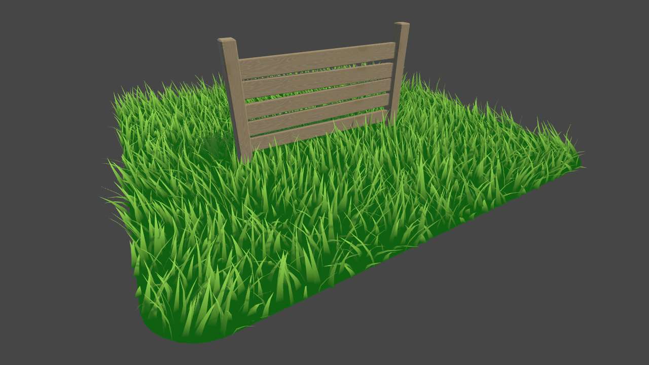
Learn to write a grass shader for Unity engine. Generate grass from an input mesh using a geometry shader, and control the density using tessellation. The blades of grass use a random function for size and angle variation, and cast and receive shadows.
Tysm, I came across that one, but then wondered if possible how I could spawn quads through the geometry shaders and place a custom grass texture on them
You don't have to look for it, it's ok. Was just wondering, ranting over the low availability of comprehensive resources. But ty for your kindness.
Is there a way to set a global shader variable (ex: Shader.SetGlobalFloat) in editor? My current workaround is starting playmode, moving to the value I want, then closing playmode... but that's super-hack of course.
@atomic echo Does calling Shader.SetGlobalX outside playmode not work?
Haven't tried. Didn't want to make an editor script if there's already a UI for it.
@atomic echo There definitely isn't
Cool
Something here is causing the base texture to become brighter.
I wonder if it's the add 😴
🤔
I mean I'm just combining the color values that are clearly not making it pure white at the start.
you're adding values together, and getting an additive result, I don't really know what you expect
what do you want to happen? I don't understand your description
I'm passing in the texture's color to be blended with another texture
and I can't(shouldn't) include the alpha value, so I tried just combining the other 3 together.
if you don't want the alpha just use a split and a combine
WIIIIIITCH!
Now I'm having an issue with the second texture. I know I'm doing it the wrong way, but I don't know what the right way is.
see how the texture is whiter than the first one (first one being the one from the previous issue), but when I pass this one into the Blend node, they are both the same brightness.
I need the chunks to stay brighter.
don't worry about the alpha stuff on the bottom
I wish the nodes had tooltips. xD
Using the x2 Add node approach here seems to have worked.
I'm trying to save my shadergraph but I get theses errors
I was able to save it a few minutes ago
Also I can't add anything, can't disconnect anything and can't copy past anything
Same thing if I create a new shader
I can't even move any nodes
Hello, does anyone know if it's possible to blend terrain chunks together? I am getting seams in places. They are set to the same grouping ID. Cheers
Anyone able to help with what I talked about earlier? Scroll up a little to find it. Don't really wanna post the same thing again
@sonic plinth basically, a drop shadow is similar as the outline here : https://www.youtube.com/watch?v=MqpyXhBIRSw
But you offset the UVs in the direction where you want the shadow to be

Thanks to NVIDIA for sponsoring!
Learn more about NVIDIA Studio► https://nvda.ws/38AaA8K
Razer Blade Studio laptops► https://www.razer.com/studio
In this video we create outline effect using 2D Shader Graph!
● Learn more about 2D Shader Graph: https://youtu.be/5dzGj9k8Qy8
...
IF you want to make the shadows bigger than the object. Else, if you want it to have the same size, just sample the texture with a UV offset and pick the alpha to have your "shadow mask"
(Sorry, I put the wrong link, corrected)
If I just make the shadow bigger you can see where its fully black. I just want to make the shadow reach further out.
having it be bigger won't do that
I'm not sure to understand what you mean here.
But the shadow can not go further than the sprite's mesh itself
That's not what I meant, I'll show a picture of what I mean. Give me a moment so I can get it back to when it was bigger.
If the UV is just made bigger it would look like this.
The shadow length is the same as before.. Just now you can see the inner part of it
That's not what I was saying. Have you watched the tutorial ?
Alright I'll watch it, I thought it was using the same method as I tried before.
I believe @sonic plinth wants to fade the effect the further out it gets, perhaps a blur might do this better than an outline.
Simplest is probably method currently in use but apply it two or three times at different sizes with different opacities.
but would be better in one go if possible
Yeah I just want to fade the effect. I can try that but it might look hard at some positions?
possibly because it's getting scaled up... the alternative is to do an offset in multiple directions. but that may be slower I don't know
some sort of blur would be better as it might not even need scaling up
Not sure how to go about bluring it though
✅ Get the Project files and Utilities at https://unitycodemonkey.com/video.php?v=dKsqupXLuSU
Let's make a Blur Effect Shader to apply to our Sprites in Shader Graph!
Check out the entire Shader Graph Tutorials Playlist
https://www.youtube.com/playlist?list=PLzDRvYVwl53tpvp6C...
it's not perfect, but might do
This blur is also doing the multiple samples trick.
If you want to save perfs, the ways to go would be using signed distance fields, but this requires a bit more pre-processing of the sprites
Nice explanation of Slimes Rancher tech art about how SDFs can be used : http://forums.monomipark.com/viewtopic.php?f=10&t=10098
Doesn't seem like there's an actual optimal way to do this
use a texture @sonic plinth
What do you mean
@devout quarry after restarting unity at least 10 times it fixed by itself
Yeah but still
What you said is a known bug with shadergraph that was fixed in an update
I have the latest version of URP and Shadergraph
@heady jewel try turning on the main preview in the shadergraph
updating SRP fixed it for me
how do I do that ?
in package manager
select URP or HDRP package whichever one you're using
and update
and if you don't see an update, make sure you enable 'view preview packages' so you see the latest ones as well
not sure it shows me anything, I have latest 8.1 right now for URP and 2020.1.0b11 for editor
managed to fix it by deleting a node, after that it started to work
oh, I had that disabled
and you have 8.1 installed?
yes, just updated
And that fixed the issue?
nope, what fixed, was deleting a node after that it started to work
@heady jewel you on 8.1 as well?
at least it works for now
So I figured out the reason this was crashing was because of some particle effects in my scene. If i keep them turned off or on a different layer it doesn't crash. I think that's weird, but it should be fine. I still can't figure out why this isn't rendering the objects on the layer though.
expected result
actual result
Hullo! I'm trying to create a health bar shader kinda similar to the league of legends healthbar. This is what I have so far and it all works good.https://hatebin.com/zpnocnepff
Here's what it looks like
So on to my question, I've been tinkering with this for hours and I just can't seem to get it to work. In league of legends when you get a shield, it sort of shifts this whole thing to the left, and tacks the shield on the end of the healthbar
I can't seem to get that to work
See my terrible picture for reference
Anyone have any suggestions? Thanks in advance!!
can you add the shield amount to the maximum health? that would shift the current hp left and let the shield part show behind it if you make the fill amount for the shield (current hp + shield) / maximum hp
ive only made hp bars using UI canvas tool but i think it should work
Totally!! I think that would work
u might need 2 max hp values one with shield and one without so u dont heal for your shield amount
if that makes sense
is it possible to place flowers on unity terrain with the petals facing up and the stem facing down, but using the terrain system for optimization?
trying stochastic texturing on sg/master-stack 😄 Warning in Graph at Assets/New Shader Graph.shadergraph at node Sample Procedural Texture 2D: Validation: Sample Procedural Texture 2D Node is not allowed by HDRP implementation
I feel like this is the best category to ask this - is there a good way to combine multiple textures via script at runtime so they can be assigned to a material as a single texture? I have a model that uses only one texture, but since I'd like to let the player choose colors for different parts individually, I'd like to be able to split it into multiple textures and then stack them on top of one another before applying them to the material. Thanks in advance!
could use custom render texture for it
or substance plugin (need substance designer to authoring)
doing the coloring realtime on a shader basically only requires one extra texture lookup tho, it shouldn't be that expensive
Custom render texture?
I'm just looking to do it with as few additional requirements as I can, and I didn't really want to edit the shader unless I have to because I know basically nothing about shaders. I'll probably have the texture split into 5 or 6 pieces from what I recall (not at my PC right now).
Would it not just be easiest to split it into multiple textures?
I'm not sure how difficult that would be. I have like zero experience with texture mapping and I didn't make the model myself
I feel like sticking with one texture is convenient because I could have the textures merge on the editing screen, save the merged texture, and just load that when it actually needs used instead of having to retrieve each texture individually?
That's just my thought process though, I'm still pretty new to Unity so I'm not well-versed in what the best options are for these kinds of things.
for coloring part x of the texture, you'd just have a mask texture with specific color and then tint that masked area from original texture with the preferred color
if you need only 4 custom colors, it's simple, just one mask per texture channel, for more colors, you need to make bit more complicated shader
Is this like a Minecraft custom skin type deal?
No, it's for a fighting game where I want to let you choose your character's shirt, pants, hair, etc colors individually instead of using preset color combinations.
So you're still choosing from a preset collection of textures for each section but you can use any combination of those.
But obviously I don't want you selecting those on the character select, so there's going to be a separate customization screen a la Tekken 7. In my head it makes the most sense to merge everything into a single texture and save it from the customization screen so I can just load that single texture from the character select.
This may not be the best way to do it so I'm open to other suggestions but that's my first instinct.
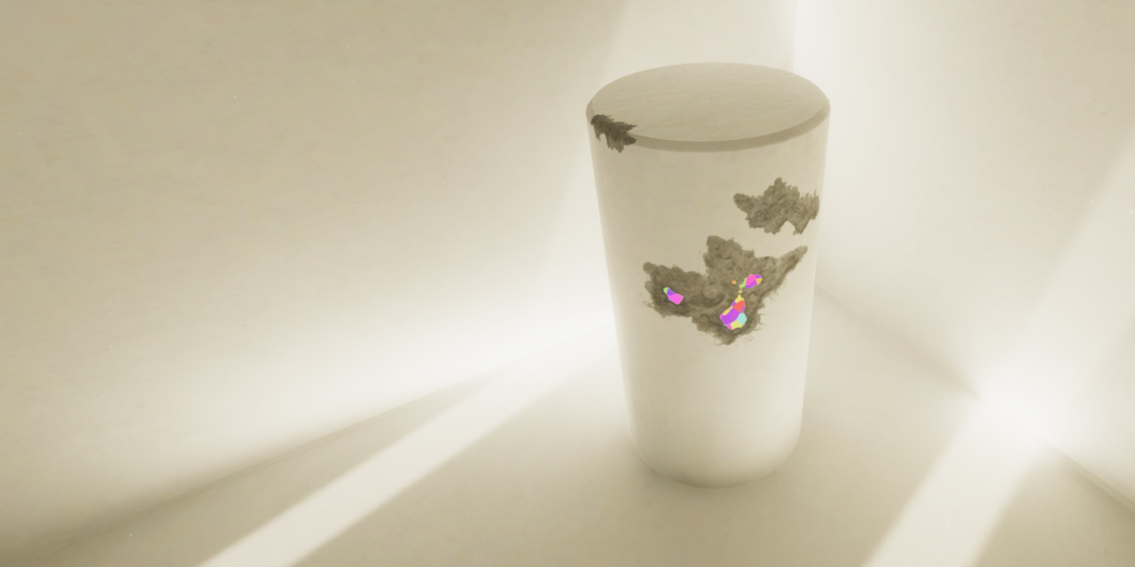
https://www.youtube.com/watch?v=_Q3YGZFRv6s
Oculus Quest Liquids!
Download here: https://github.com/aniruddhahar/URP-LiquidShadergraph
Also, you don't need VR to run it, it can be used in any URP project.
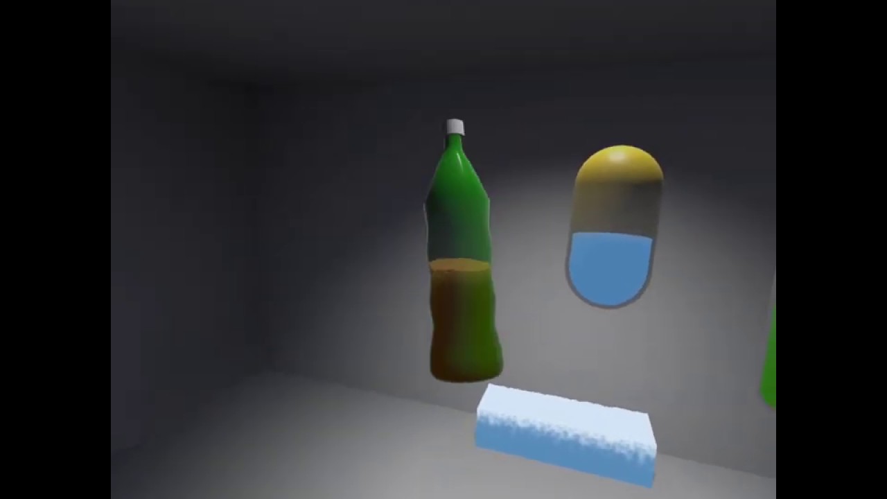
Procedural Shader graph for interactive liquids in Unity URP
This is a shadergraph to 'fake' interactive liquid simulation in Unity's Universal Render Pipeline, made with the goal to bring really cheap, and adjustable interactive liquid behaviour to lightweight rendering appli...
GitHub
Simple Procedural Shader graph for interactive liquids in Unity URP - aniruddhahar/URP-LiquidShadergraph
that is very cool! I think I'll have to dive into that to see how you made it
@scenic furnace https://twitter.com/minionsart/status/986374665399685121?lang=en

Here's how I made my fake liquid shader using solid color backfaces and movement from script. #gamedev #unitytips #indiedev
Shader code and C# script with comments in first reply!
More tips and tricks >> https://t.co/FqAsMb9Plg https://t.co/WDsOFsgWkO
Retweets
2857
Likes
10495
Shader noob. I've got a basic triplanar shader. is it possible to render different textures at different heights?
while keeping triplanar texturing?
I want to try my hand on raymarching/SDF shaders for volumetric effects but _what happens when the camera intersects the geometry that hosts the SDF shader?
I mean, if I have like a cube with a volumetric cloud effect, does it get cut off as soon as the camera enters one face of the cube?
Shader noob. I've got a basic triplanar shader. is it possible to render different textures at different heights?
@coarse path yes, if you use the heightmap info to sample the right texture
@regal stag do you think its worth investing learning shaders ? i am normally a C# coder, i am doing a solo project so i think i need to learn other aspects of game development such as shaders, i saw your recent post about shaders, but was wondering if its worth invest in learning shaders or shader graph, i really like shader graph (because its node based and requires 0 shader coding knowledge), so what would you suggest to someone that is new to game development and will go solo iindie for a while ?
I'm trying to render a render texture to a plane, but the plane is just white? What am I doing wrong? 🤔
Fixed: Even though I set my Render Texture in the Blackboard, it somehow didn't get set inside the material itself. APplies it there and does show the render texture
Hello! I have question about "Position" node. When I select space "Object" will the output values be from -1 to 1 ?
@plush bane Not necessarily, no. The positions will depend on how the model was made & imported, they can be outside the -1 to 1 range.
@violet kelp I'd say learning shaders is worth it, and shadergraph certainly makes it easier to get started.
@regal stag I can't create a very simple thing in shader graph. A gradient thing. Object is black at bottom (Y axis) and get greener and greener on top.
The idea was to use Position node. The bigger the Y, the greener the thing
You can still assume the positions are in a -1 to 1 range in order to do the gradient, but they don't have to be
But I would have to know min and max in order todo this
If you want the gradient to work for all meshes (and be exactly black at the bottom of the mesh, and green at the top), then yes, you'd probably need to know the mix/max and send them in using properties.
Or model them so they always range from -1 to 1.
Alternatively, you could UV map the model by projecting uvs from the side, and use the UV.y as the gradient instead.
Hmm thanks will try
I want to combine 2 camera's but not as layers. but by Mask. How would I do this in HDRP ?
Example (good golly what amazing art work)
Interesting. I have an FBX object imported. It's not rotated, scale 1, etc. But when it comes to shaders it's Y is swapped with Z. How is that possible?
Is this from Blender? Because I know blender is z-up, while unity is y-up. There's probably settings to fix it during export. (You might have to look at some tutorials as I've never really exported things properly lol)
@violet kelp you dont really need to understand text based shaders with shader graph, only if you need some custom functions not provided by sg. Writing text based shaders yourself from scratch with current srps is not even feasible at all
That being said, main thing to understand about shaders is that they are just math
@fervent tinsel
Writing text based shaders yourself from scratch with current srps is not even feasible at all
For lit shaders, I understand what you mean. For unlit shaders, it's no different except some macros if you want to support SRP Batcher.
@low lichen only for lwrp/urp afaik
Yeah, I should have added that. I've only used URP
Hdrp complicates even simplest things
Some of the old style passes still work tho
Surely there are some includes you can add that do most of the work for you?
The issue with working on hdrp shaders manually is that their api evolves a lot between versions. Keeping your custom shaders up to date between hdrp versions is a monumental task
I've done it in past and wouldnt recommend to anyone
Just use SG if you can and your port to newer version is one button press (resave for graph)
I would recommand putting all you code in a custom SG function node, and let the rest live by its own
Exactly
Render in two RT, and mix them in a dedicated shader ?
And then how do I apply this dedicated shader to the full screen?
Apply it to a UI quad 🙂
Oh - interesting
Or, you can just render one, and apply it with the mask transparency as a full screen UI image
Do you need the mask to be able to blend between the two? If you need it either or, then you should be able to use the stencil buffer, assuming HDRP supports that.
HDRP doesn't support that.
it doesn't
You could do a trick with the depth buffer though
I eventually need the masking of the 2 camera's to be based on the distance to a certain game object in the world
Just draw a quad in front of the camera with depth only to block a portion of the screen
But I can mix the mask in that case
Then draw the second camera after drawing the first
I think the applying to a UI Quad is def more of a solution I like
If you need to blend, then yeah you need to do it in a custom pass
I don't think @amber saffron meant a custom pass.
Just render both camera's to a Render Texture and mix them in another shader based on the Mask
That other shader would be the custom full screen pass
What's the effect you're going for?
So you want the shield sphere to sort of act like a portal to see something else?
yea basically
but only once you're close enough
so hence the combination of camera's based on the mask
which in turn is based on distance from shield sphere
So the portal image would appear as a growing circle as you get closer to the edge of the sphere?
With faded edges?
If you know that the mask is based on a sphere, you could also do all this with one camera
and make a custom shader applied to all the objects, that "cuts" them based on a distance test
Ye I was thinking of that first as well - but I don't like that approach for a multitude of reasons
So I'd like to continue with my current "thought train"
Might lead to some shadowing glitches tough
Yeah, that's what I anticipated, which is fine
How would you go about creating a mask in real time based on the sphere?
in this case - from a different angle the mask would obv look a bit different cause It's colliding with geometry
But also the white part might include some of the sphere in the distance?
How close is close enough to see this portal image?
Should be based on a distance number eventually
first things first though is creating a mask based on how and where the sphere collides with other geometry
But also the white part might include some of the sphere in the distance?
@low lichen how so?
Because the parts of the sphere that are far enough away from the camera would not be included in the mask?
To form this portal circle with faded edges
In the last screenshot, the camera is closer to the left edge of the sphere, so maybe only that part would not be in the white mask
in this angle the mask would look like this
it'll be a mask based on view basically
oh yeah, forget about that statement
I'll need the mask nonetheless
for some other stuff
I just need to be able to create a mask based on the Main Camera view
I can describe how I would do it in URP, but I don't know what translates to HDRP
Give it a try - I'll take anything over nothing 😄
If you have a depth buffer of the scene geometry, then you can use that buffer to draw the sphere to a separate mask render texture with a custom unlit shader with ZTest Greater and just return full white in the frag shader
Then, assuming the mask render texture was cleared to black, you'll have a texture that is white wherever the sphere won't be visible
When you set the render target, you can use a depth buffer from another render texture, like the depth buffer of the scene you render before all this.

lol, seriously though - I understand the thought process here
but no idea how to do this in HDRP >.<
Not sure how scriptable it is. Don't think it has renderer features like URP.
Apparently is has Custom Passes instead which use the post processing volume system, I think
There is no "pp" volume system, just "the" volume system
But yes, you could use a custom pass to render only the masking sphere with the scene zbuffer, to a separate buffer (custom pass color buffer), and use it a the mask.
But yes, you could use a custom pass to render only the masking sphere with the scene zbuffer, to a separate buffer (custom pass color buffer), and use it a the mask.
@amber saffron sounds difficult - got a tutorial or reading material somewhere for me?
Best I can give you is this custom pass examples project : https://github.com/alelievr/HDRP-Custom-Passes
GitHub
A bunch of custom passes made for HDRP. Contribute to alelievr/HDRP-Custom-Passes development by creating an account on GitHub.
any other way except for this custom pass to generate the mask I desire?
Hum :/
Add a camera with clear depth only, a black BG, and render a inward facing opaque white sphere only there, in a RT
That way you will keep the depth of the object, and parts where the mask is not behind it will be white.
Does anyone know why my shader won't give a proper outline with color on a image with white borders?
Should look like this :
@amber saffron Won't that clear the depth of the scene though? Or does Clear Depth Only mean it only clears color and not depth?
Maybe something to do with the colors being added?
Sorry, I indeed inverted the idea : clear color only, not depth 😄
Is there an event hook for right before the camera renders in HDRP? You could then turn off clearing on the camera and clear just the color manually using GL.Clear
Hum, sorry, that was a wrong memory I had of the setting.
It's not possible to not clear the depth in HDRP
So the custom pass option is probably you best choice here.
I tried with the Culling Mask of the camera, but that leaves me witht he full mask instead of the mask that also incorporates the surrounding geometry
It'll do for now for testing, But I'll eventually have to look into custom Passés - thanks!
@grand jolt For the sake of seeing if it's possible, I made something that looks like your effect by using a custom pass.
Care to share? 😄
Yep, cleaning up a bit and will send a zip
You're a god send - I tried 2 different camera's for testing purposes and using RT with a hand made 50/50 mask - but my 2nd RT seems to lag compared to the first so idk what I am doing wrong
(imma try and share a video in a couple min)

check Game Window - there is a mask - and I got to use 2 Camera's but as you can see it seems to lag behind a little and isn't smooth at all
https://drive.google.com/file/d/1TGHzT-vveOot5Uol4zrae5EPIJP7HHTi/view?usp=sharing
My setup here :
- Render the camera of "outside" first
- Using a custom pass "before rendering", draw only the sphere in the z buffer
- Render the camera of "inside". Everything outside the sphere is culled due to the z test.
I've also enabled the light layers in the HDRP asset and set up the lights/objects so that the two "worlds" don't interfere.
Google Docs
U went insta with that just released LTS version :p
Oh, yeah, sorry. You should be able to open it in 2019.3 still
Np, downloading LTS now 😄 hehe
Thank you for the help
btw,have you looked at the video? I tried to do it. but the cameras seem to lag in relation to one another. any idea why?
I need to be up to date
Maybe depends on the rendering order of the cameras ? If the one that write to the RT is rendered after the main one, then the display in the UI is kind of delayed to the next frame.
Is there any reason for a scrollview to not be properly masked when rendered through a RenderTexture + Camera?
Maximum number (256) of shader global keywords exceeded
How can I fix this?
@grand jolt The documentation talks about that here
https://docs.unity3d.com/Manual/SL-MultipleProgramVariants.html
What does "alpha tested" geometry mean?
Alpha geometry is queued separately from normal geometry (so it is more efficient) ||@fair sleet||
ok but what's the difference between normal geometry and alpha tested geometry?
AlphaTest refers to shaders that use the hlsl clip function to discards pixels if their alpha is below a certain alpha cutoff/threshold
that sounds like exactly the thing I need
how do I use it?
clip(alpha - threshold); in a fragment shader
The alpha is commonly obtained from a texture, and a threshold could be set as a property
that's pretty convenient
I need to set the RenderType in the shader tags to "Transparent" right?
thanks
I think there's a "TransparentCutout" that's typically used with this kind of thing
ok I will use that
float angle(float2 a, float2 b)
            {
                return (acos(dot(a, b)) + 1)/2;
            }
Is this function correct? It should return the angle between two vectors as a range from 0 to 1
I might be wrong but dot will return a -1..1 range right?
and acos is cos^-1? so it will return an angle in degrees?
and then you add 1 to that angle?
wait
I read the docs wrong
I thought acos returned a value from -1 to 1
I think if you lose the acos, it should work?
dot returns [-1,1] range, so you add 1 to get [0,2] then divide by 2 to get [0,1]
dot product only doesn't seem to work
Dot product returns 1 if the vectors are aligned and 0 if they are perpendicular (90 deg apart), (and -1 for opposite directions), so isn't the same as angle alone. I think the acos is to convert it to an angle in radians - might be between 0 and pi then? So if you want 0-1 range, divide the acos result by pi? Bit of a guess
that makes sense to me
it seems like converting the value returned by acos worked
man the documentation is so bad
it doesn't say if acos is in radians or degrees or (-1,1)
so just like this? return acos(dot(a, b))/pi;
I think most times it's radians when dealing with calculations
you're right
for some reason I thought it would return a range between -1 and 1
cos takes in an angle and returns -1 to 1 range
acos is inverse, so other way around
I got confused again (doing return degrees(acos(dot(a, b))) looked like it worked ) but it seems like return acos(dot(a, b))/pi; works perfectly.
actually nevermind
it gives me the right angle but it's clamped between (0 and 1) so I can't figure if the angle is clockwise or anti-clockwise (i need something like Vector2.SignedAngle)
Managed to some research and settled on this.
I only need the angle between the vector and the y axis so this works.
float SignedAngleOy(float2 a)
            {
                return (atan2(a.x,-a.y) / pi+1) /2;
            }
What is that sampling method for rendering outlines called? On line 108 https://github.com/alelievr/HDRP-Custom-Passes/blob/master/Assets/CustomPasses/Selection/Shaders/02_Selection_Fullscreen.shader
GitHub
A bunch of custom passes made for HDRP. Contribute to alelievr/HDRP-Custom-Passes development by creating an account on GitHub.
I don't get why it works.
In fact, I don't get why the whole shader works. The sampling itself fills the mesh but then a hole in an outline is rendered somehow.
shader made with shader graph are all supose to work with webgl or not?
im trying hard to have my water shader work on a tilemap and it work fine in editor but not loading in webgl
not sure what im doing wrong
Holy heck, I finally got it. This shader extends the object's silhouette beyond its original edges in the color buffer and then subtracts the original silhouette to get the outline. Holy shit was I slow to figure that one out.
@near pond sounds like it may not be in the build https://answers.unity.com/questions/458190/build-not-including-custom-shader.html
Unity is the ultimate game development platform. Use Unity to build high-quality 3D and 2D games, deploy them across mobile, desktop, VR/AR, consoles or the Web, and connect with loyal and enthusiastic players and customers.
Hello, I would like to know how I could do to have the bottom of the water while keeping my wave effect above.
Anyone have a little help or tip ?
@gloomy oasis I guess it's placed on a cube, so try multiplying the wave texture with max(0,worldNormal.y), or lerp with this normal value between the top effect and bottom effect, whichever works best
yes it's placed on a cube and i will try ty
You will need at least a 3D noise for that. 2dimensions for uv, and 1 for time
If you don't have this, it will be a 1 dimension animated noise.
I just want the noise to move horizontally
OR you can juste scroll the uvs
ok
add the tilling/offset node
and input the time in the offset vector, to make the uvs pan
And how can I turn time into a 2d vector?
doesnt the time node output a float? should just combine those 2 together with a node
vector2D node
Ah, should've just searched that
Yes, the append node exists, but in that case the simple vector2D is the same
When I insert that into the alpha of the main node, literally nothing happens. Why?
Did you set the master node to be transparent ?
I don't know what that means, so probably not
click on the cogwhell in the top right of the master node, you will probably understand what I'm saying then 🙂
Ah! Thanks
Hello. I tried to use "Transparent shader with depth writes" from there: https://docs.unity3d.com/Manual/SL-CullAndDepth.html and it doesn't work as intended. The result corresponds to the picture to the left. I also tried this one and got the same result: http://wiki.unity3d.com/index.php?title=AlphaVertexLitZ
Here is a test project I made to showcase the problem: https://github.com/QuasiStellar/test
Shader itself: https://github.com/QuasiStellar/test/blob/master/Assets/Materials/transparent.shader
Script that applies shader to all materials: https://github.com/QuasiStellar/test/blob/master/Assets/Scripts/NewBehaviourScript.cs
Hi everyone ! How do i use a shader for a terrain in unity 2019 2.6 f1 ? thanks a lot !
Same as before : create your shader, create a material that uses this shader, assign the material to the terrain in the terrain settings.
ah ok cool thanks ! that's what i tried but it says "can't assign materials with shaders which need tangents geometry on terrain, use shaders in terrain/nature instead" but i cant find the terrain/nature tab 🙂
nature/terrain
I'm still lost on custom nodes with the new SG stack:
like, how does the new SG system validate this?
I have similar structure already as on current SG nodes with same interfaces but it still keeps telling it's not compatible
in fact, I tried to quickly duplicate one of the simplest nodes on SG:
so it's not the node structure but there's apparently something else that defines what this is compatible with
some list somewhere?
ah, found it, it needs to be listed at com.unity.shadergraph/Editor/Generation/TargetResources/NodeTypes.cs
Why was my message deleted?
@fickle jay this one? https://discordapp.com/channels/489222168727519232/497874081329184799/720216424609611808
No, after that. I just asked why it was ignored.
@fickle jay I tested your shader and it works fine for me. You're not using URP, are you?
Probably not. Can you explain?
And have you tested this shader without your script?
Just creating a new material using this shader and use it on an object in the scene
That works as intended.
So it's an issue with your script, not the shader
I noticed you use renderer.materials in your script. Are you expecting the renderers to have multiple material/submeshes?
Just creating a new material using this shader and use it on an object in the scene
In this case I just make brand new material.
And script changes shader of the existing ones.
Yes, it has multiple materials.
You'll probably need a different approach for that. What you're probably seeing is the submeshes overlapping.
Because to the GPU, they might as well be completely separate objects
What's happening now is this:
Draw Renderer:
  Mesh 1
    Depth Only Pass
    Transparent Pass
  Mesh 2
    Depth Only Pass
    Transparent Pass
What you want is:
Draw Renderer:
  Mesh 1
    Depth Only Pass
  Mesh 2
    Depth Only Pass
  Mesh 1
    Transparent Pass
  Mesh 2
    Transparent Pass
The only difference between these materials is color, in fact they are just pure color without any texture or anything. Does it make it easier?
That doesn't affect the problem
(
If you create a new material with this shader and apply it manually to one of your models with multiple meshes, does it look the same as if you ran the script?
Minus the difference in color
And you'll have to add it multiple times for each submesh
Yes, the same.
What you want is:
Draw Renderer:
  Mesh 1
    Depth Only Pass
  Mesh 2
    Depth Only Pass
  Mesh 1
    Transparent Pass
  Mesh 2
    Transparent Pass
Can I set this order manually in the shader?
why does some of my shadows change, depending on where i look and am in the game?
You won't be able to do it in a single shader. You'll have to split the passes into separate shaders, then have your renderer materials setup like this:
Materials:
  Depth Only // < That's for mesh 1
  Depth Only // < That's for mesh 2
  Regular Transparent // < That's for mesh 1
  Regular Transparent // < That's for mesh 2
@fickle jay Here's a depth only shader:
Shader "Custom/Depth Only" {
    SubShader {
        Tags {"Queue"="Transparent" "IgnoreProjector"="True" "RenderType"="Transparent"}

        Pass {
            ZWrite On
            ColorMask 0
        }
    }
}
It's just your original shader with all the transparent stuff stripped out.
@lament pagoda Change how?
He probably means that shadows are more detailed when you're close to them.
no
or well
wait a sec
sorry for the bad quality. its only bad because max upload is 8mb on discord
> Materials:
>   Depth Only // < That's for mesh 1
>   Depth Only // < That's for mesh 2
>   Regular Transparent // < That's for mesh 1
>   Regular Transparent // < That's for mesh 2
> ```
But how do I set two materials to one submesh?The way multiple materials work in Unity is if there are more materials than submeshes, it will wrap back around. So for example if you have 1 mesh, each extra material will just draw the mesh again with that material.:
1
1
1
With 2 meshes
1
2
1
2
1
2
There each mesh gets drawn 3 times with whatever materials you put in each slot
So if you have 2 meshes and set the materials to this:
Depth Only
Depth Only
Regular Transparent
Regular Transparent
It draw the first mesh with Depth Only, then it will draw the second mesh with Depth Only, then it will draw the first mesh with Regular Transparent, then it will draw the second mesh with Regular Transparent.
Can I add materials from script?
Sure, but it's a bit painful because it's an array instead of a list
So you have to create a new array
So you just set the materials array directly
How should regular transparent shader look like?
Not a special shader, just whatever transparent shader you prefer
It's the other way around
Depth only first
Then transparent
Are you trying to post code?
void Start()
    {
        var obj = Instantiate(Resources.Load<GameObject>("capital"), new Vector3(0, 0, 0), Quaternion.Euler(0, 0, 0));
        var materialsCount = obj.GetComponent<Renderer>().materials.Length;
        var newMaterials = Enumerable.Repeat(obj.GetComponent<Renderer>().materials[0], materialsCount * 2).ToList();
        for (var i = 0; i < materialsCount; i++)
        {
            var material = obj.GetComponent<Renderer>().materials[i];
            var color = material.color;
            material.shader = depthOnlyShader;
            newMaterials[i] = material;

            material = new Material(transparentShader);
            material.color = new Color(color.r, color.g, color.b, 0.5f);
            newMaterials[materialsCount + i] = material;
        }

        obj.GetComponent<Renderer>().materials = newMaterials.ToArray();
}```How many submeshes does this model have?
9
Is there another way to make 9 colors?