#archived-shaders
1 messages · Page 152 of 1
when you change values in shader graph which are public they do not update on the material which is applied to your plane in the scene
so you need to tweak them in the scene outside of shadergraph, if you get me
I started with the one you are using, however I'm in URP so if that makes a difference... I would hope not.
It's strange that it is not working
@grand jolt instead of outputting it to emission try outputting it to color, in place of your water color temporarily.
from same starting tutorial I ended up modifying until I got something reasonable, so I'm fairly certain it should work out in the end. https://cdn.discordapp.com/attachments/335329193145663493/701724777819275324/unknown.png

that look so good
i also gt this error i just notice
color is also not changing now
i mean i change the color to
@thick fulcrum i can`t change color now
@grand jolt my bad sry the output for the foam is just a vector 1, so the albedo probably won't accept that.
I would perhaps follow the tutorial to it's conclusion as he does something different with those nodes soon which may make all the difference.
its ok np
I swapped to using a foam texture myself which meant this was a non-issue, but your water is looking pretty good so far.
it could be something to do with HDRP and how emission is handled, but I'm just guessing
i deleted , i will make new one now @thick fulcrum
which pipeline should i use @thick fulcrum
Hi. I cant figure out a really simple thing. How to make gradient shader with shader graph. Like if I add it to a box, top would be green and then as it goes down it gets darker and darker
Help!!
and later if i copy that shader graph and use on different PP , is any problem going to occur
use the position.y value to sample a gradient @plush bane
@grand jolt HDRP is fine to use, but it can be overwhelming for novices and very small studio's. You need someone with time and knowledge to get it all setup right in my opinion.
URP is easier to get to grips with and more straight forward.
You should be able to copy that graph to URP without problems (I hope)
A clamp node ? 😄
Clamp not right term
Let me guess : you want 0 at the bottom of the object, and 1 at the top ?
@amber saffron ys
Use the remap node with exposed property value : in min = the minimum position that will be 0, in max = max position that will be 1. Out min = 0 and out max = 1
Why can't I expose Gradient property?
There is no property drawer for gradients in shader, for the moment
ehh
You could replace your gradient with a texture if you want it exposed, so it would only be the matter to edit the texture
Is there a way to lerp a shadergraph property in the particle system?
@grim tartan You mean the particle system component, not the VFX graph particles, right? If so, I don't think you can access specific properties directly, but you can send stuff like the particle's lifetime into the shader using the Custom Vertex Streams option in the Renderer tab. (here, AgePercent is sent into UV.z, think it just starts at 0 and goes to 1 over the particle's lifetime).
Thanks! Maybe modifying the values of that inside shadergraph would work.
like add. cause I'm lerping between 1 and 1.5
@grim tartan You can also likely use the Custom Data part (and send it into the shader using the custom vertex streams again). e.g.
That might not be over the particle lifetime though, not sure how it works as I haven't used it before
I'll try your first answer then. I am going to fade it with color over lifetime afterall
first one makes some weird effects :v
hey guys... anyone know the best way to add outlines to the tilemap sprites with shader?
got it working. thanks @regal stag Option 1 is indeed lifetime
Nooby question incoming: I'm straying away from the safety of shader graph into the scary lands of text-based shaders to modify tilt brush shaders
One thing I'm struggling with is how to pass custom data from a vertex shader to a surface shader. With a vert/frag shader the vertex shader returns a struct that is passed to the frag shader, but I'm not sure how info gets passed from the vert to surf shader.
In my case, the vert shaders writes to an inout appdata_full struct which seems to be a preset struct with common values needed for a surface shader, but the surface shader has arguments for an Input and SurfaceOutputStandardSpecular struct. What is the correlation between appdata_full in the vertex shader and the two other structs in the surface shader?
I'd like to pass some custom values from the vert to surface shader but can't figure out how.
@tardy spire Looks like the "Custom data computed per-vertex" example on this page is what you want : https://docs.unity3d.com/Manual/SL-SurfaceShaderExamples.html

Ah this is the documentation I was looking for, thanks!
ah ok, so I just need to add an out parameter for an Input struct and Unity will know to pass it over.
Hey
Does anyone know what the constructor for a sampler2D object is?
I can't seem to find it written anywhere.
@tardy spire Or just copy the "appdata_full" into your source, rename and customize it. The surface shader will use a custom structure, you're not absolutely stuck with what unity gives you. But it has "expectations" if you're doing lighting and stuffis (which, with a surface shader, you are). So be careful what you remove if you want it to work. But I think most of that is in the output structure.
gotcha, thanks @meager pelican!
For mobile loading non-power-of-two textures at runtime via UnityWebRequest, is there any side effect?
I've been reading around and it seems that POT is really only a thing when importing texture due to compression algorithms work better with them, however I'm not sure if that's the whole story.
@marsh sparrow This???
https://docs.unity3d.com/Manual/SL-SamplerStates.html
There's macro helpers too. See "Texture/Sampler declaration macros" here:
https://docs.unity3d.com/Manual/SL-BuiltinMacros.html
I see.
I'll look into it
Hey, uh
I'm not sure this is supposed to do this but
I created a new Surface Shader, just a general one. I didn't modify it, I didn't touch it at all.
I applied it to a material.
And then the material turned pink as if there was an error.
Do any of you know how I'd go about fixing that?
If you are using URP/HDRP, surface shaders aren't supported.
You can write shader code but it needs to be the vert/frag kind instead
How would I go about just making a new shader, and just making it work. No need to actually tell me how to do anything else.
All I need is that starting point.
I'm getting really annoyed by the shader graph and the lack of float array support in the ports.
I think there's an "Unlit Shader" option or something which is the other shader code template
I see. It's unlit, though. Does this mean it will not interact with light?
Yea, unless you handle lighting stuff. This is a good template for a PBR shader for URP here : https://gist.github.com/phi-lira/225cd7c5e8545be602dca4eb5ed111ba
God I just wanted a float array...
It just hurts to manually put them in.
One by one
Has no one ever had this issue?
Did the custom function method not work?
No, because I run into this issue eventually:
Let's say I have 4 float inputs.
They're used to segment some object into different parts.
Alright?
What if eventually I'll want to have more than 4 float inputs?
What if I'll want to have 16?
It's a massive pain to actually stay there and make more input ports with specific names.
I say this as I have a custom node with more than 40 input ports right now.
Around 50 even.
And the same 40-50 parameters on the blackboard.
All named properly.
You can imagine how much time that took me, right?
Why not just have a float array type parameter?
Why not just, you know, have an array type, or hell, I'll even take a list if it means I don't have to make 50 input ports and 50 parameters each with their own proper reference names.
II remember at one time the float array type was in the shader graph. Where did it go?
If I knew how I'd even go and try to implement it myself, but I don't know if Unity even lets you add custom data types to the shader graph.
But really, does anyone know how I could use a float array inside of a shader graph?
I'm not entirely sure what you mean by "segment some object into different parts", but it sounds pretty complicated if you need that many float properties
I just need to have a float array that I can change the size of while editting, but not during run time. Nothing will change during run time. It's only for editting purposes.
I see. It's unlit, though. Does this mean it will not interact with light?
@marsh sparrow
Use SG to generate a lit shader. Modify it manually from there. 😉
SG?
Shader Graph
Then put one in AFTER you generate the template.
SG is a CODE GENERATOR.
Oh?
Yeah, if you right-click the master node there should be a "show generated code"
Wait this might be
What I need
Give me a second lads
Also
If I add it after the code generates, will it destroy it if I recompile it?
Let's say I modify the SG.
But once you customize it, you can't go backwards.
But you can use it to make any simple SRP template.
Just generate a basic lit thing so you hvae something to customize.
Yeah, 99% sure it will, particularly for "something it doesn't support" that you added. 😉
God damn.
Well.
At least it will do what I want it to do.
I just can't stand adding manually 50 ports.
It's such a pain and I really think that the devs should add the float array feature to the SG. It'll really help with development.
The generated code will just be a separate file to the graph, I think by default it's just a temporary file so you should re-save it somewhere in your actual project assets. You can go back to the graph, but it would be before you added those changes.
I see. I should just give it the hlsl extension, right?
Or does it already have an extension?
I think it's probably a .shader?
I think/read that custom-data of some sort is on the radar screen.
But at least you can generate a template of the type you want, and go from there and don't have to start with a blank page and a largely not-documented-yet API.
Wait...
what
It generated a
221k loc file.
It generated low level code.
//////////////////////////////////////////////////////////////////////////
//
// NOTE: This is *not* a valid shader file, the contents are provided just
// for information and for debugging purposes only.
//
//////////////////////////////////////////////////////////////////////////
// Skipping shader variants that would not be included into build of current scene.
This is also the first thing inside of the file
That's not what you want.
You're looking for a "show generated SOURCE code" (or whatever it says). You get it from right-clicking on the master-node in SG. Should pop up in 2 seconds.
Oh yeah I accidentally compiled it
oops
Alright I think I see it now
Holy crap it's a 10k LOC file
right click the master node in shadergraph
I did
I clicked Show Generated Code
Is it because I used a HDRP SG?
I'll try it out with a regular SG.
Maybe it's different in HDRP?
Maybe. I'll use a regular PBR SG now to see if that's the culprit.
If you want lighting, that's probably the one you'd want anyway for an HDRP project.
Holy crap the regular PBR SG generates a 3k LOC file.
Damn it
I think I'll have to use an Unlit one.
All I want is just a shader for an object, an object that could behave just like a regular terrain.
Terrains are lit. And often complex ("regular terrain"?)
Yeah, that's the thing.
But in the past you would just generate a standard surface shader
And it would do the job
Holy hell even the Unlit one is generating a 2.3k LOC file.
I'm "importing" still. Please stand by. One moment please.
We'll return you to your regular program soon.
Hah, yeah, no problem.
Oh, well since your masochistic, you'll do fine here.
(Still "importing"...)
I think that's true considering I made 50 different input ports for a node and 50 different blackboard parameters specifically for those 50 ports of a custom node.
It was a pain. 2-3 hours just to set that up.
OK, so I created an HDRP lit graph.
right clicked on the master node. Selected "Show Generated Code"
Yes. That's what I also did.
And got 9500 ish lines of code in Visual studio
Welcome to my world.
yes, the HD shaders are large c:
yes, the HD shaders are large c:
@stone sandal Probably OK. We've all agreed he's masochistic.
Not THAT masochistic.
lol
I don't even know where to begin with this.
They are totally different than the good old standard surface shader.
Well, maybe feed it some color data or something simple in a simple graph, so you can see where your variables go, then add your array somehow???
I'll... see where that gets me.
No, there's actually no way for anyone to manually write this.
It's the same code in multiple places.
So there's multiple render passes, right?
Well in each pass there's pretty much the same code. I added a parameter to the blackboard and I made it be the base color of the shader by directly linking it.
In each of the rendering pass I see the same code.
Minor differences in the #ifdefs before the actual code.
the graph code gets populated to each render pass based on what that pass is responsible for yes
Could I ask you a question pertaining to shader graphs in private?
hey, we try to keep all conversations in the public channels in case someone else can be helped by the information
please don't DM employees c:
Alright. I'd especially like others to know about this.
So... All of this started from needing a float array data type in shader graphs.
have to answer here, but do keep in mind I am working
theres no reason you cant include a float[] field in a custom function node and set that as a shader property from code, as far as I am aware
it wouldn't be a node input because then youd have to specify all the input ports
Wait this is it
So I create a custom function node, alright, that's what I've done before, but then I have to set a shader property from code?
how else would you specify it?
She means C# side code
That really was the biggest issue that I've had so far.
No, I understand she meant C# side code.
So, any custom function node can access the shader properties?
yup, so long as they are defined
Does anyone have any insight about vertex streams for particle systems? I made a vertex animation shader but when I try to use it with particles it goes bonkers. I tried to look up some stuff on vertex streams but I can't wrap my head around how to implement them (I'm using ASE for the shader creation) https://gyazo.com/16eb1cfc276baa617cff00761295275c
I may have not understood something
So I'm including a float array field in a custom function node, alright?
But how do I actually set it as a shader property?
My custom node script looks something like this:
float testFloat;

void main_float(...)
{
...
}
Alright?
That's just a float, not a float array. You'd want something like float _FloatArray[10];
No, I know it's just a float, right now I just want to make the connection between the custom function node's data and the C# script.
Do I just go:
material.SetFloat("testFloat", 0.65f);
?
No, I know the SetFloatArray and how it used to work, I'm asking whether I can just call the SetFloat / SetFloatArray directly
Wait so
Yes, although it would have to be a property in order to use SetFloat, right? You can use Shader.SetGlobalFloat without it being a property though.
when I wrote that float testFloat; inside the custom node script
It suddenly becomes a property of the shader?
I don't see it in the properties of the shader when I click on it.
its not something included in the Property section of the material, so it wouldn't show up in the inspector
Well... if it's not part of the property section of the material
How exactly do I reference it?
By that I mean through an external C# script.
You can still call material.set and material.get on the string lookup of the value.
@regal stag might be right but I dont remember having to explicitly set a global variable when the shader had an unexposed value.
so it should just be material.SetFloat like you suggested
I did this, though.
It's not working.
I have a script that updates the value of the material while in the editor.
I always thought material.SetFloat had the requirement of it being exposed, but I might be wrong, I really don't know.
I press a button and it calls
material.SetFloat("testFloat", 0.5f);
So the testFloat inside of the custom node script should have its testFloat variable updated to 0.5f
Yet it doesn't.
I assume you are outputting the result as a colour to preview it somehow
The custom node has an output of a float that is connected to the master's base color. Basically if the color I'll see is not black it should be working, but it's not changing from black.
I assume you are outputting the result as a colour to preview it somehow
@regal stag Yes.
It's a grayscale, but I just need it as a proof of concept.
Out of curiousity, what happens if you try Shader.SetGlobalFloat("testFloat", 0.5f);
the shader?
no just the static class
ah my bad, misremembered from last time I did something like this
... nothing
I thought I saw something change but the material's color is still pitch black
I really don't think Unity sees that ```csharp
float testFloat;
that sits inside the hlsl file
That seems strange to me, I assumed that would work. Are you sure it's actually outputting the value in the function correctly, and it's hooked up to the master? Definitely saved?
I'll check it again just in case
And make sure the Shader.SetGlobalFloat code is actually running
I'll add a Debug.Log() to see if it's running just in case. I know this function is running, but it's better to be safe than sorry.
Yea
oh nice now the shader is not responding whilst compiling
oh
it works now
It does actually change the color
For some reason I can't see it in the game view, but it doesn't matter
The Scene View shows it properly
Let me try it now by calling it locally
Without the global part
... Now it works??
what
I'm legitimately confused. Why does it work now?
well either way
I guess this solves it.
Maybe the shader wasn't saved properly or something, who knows 😅
or it was just taking a while to recompile, etc
probably
Well now it works
I'll post a TL;DR for those interested
Variables of custom function nodes are actually stored in the Properties section of the shader/material, but they are not exposed, that means you don't see them in the inspector.
To interact with them, use an external C# script and use their exact variable names, such as this:
Custom Function Node file
float testFloat;

void main_float(out float grayscaleOut)
{
    grayscaleOut = testFloat;
}
C# Script
public Material testMat;

void SetTestFloat(float someFloat)
{
 testMat.SetFloat("testFloat", someFloat);
}
also keep in mind that this is totally a workaround for the fact there is no vector array types. Fully supporting that in shadergraph would require some code on our end, but if it seems like a necessary case please request it on our roadmap! https://portal.productboard.com/8ufdwj59ehtmsvxenjumxo82/tabs/7-shader-graph
Product roadmap and feature requests. Welcome to our product portal.
also this way you could technically use whatever kind of data type you want as long as hlsl supports it.
yup
or really you could make your own structs this way, too.
this is just for those that might stumble upon this.
that one I am less certain of
well, regardless, the next masochist will find out down the line 😆
also this was fun. Thank you all for helping me out!
glad you got it working!
I didn't know you could use material.SetFloat on non-exposed properties, so that's cool
I think it has to do with the property sheet that gets passed around by materials
Ill have to double check that in c++ land though
it's probably there but it's just not exposed
I know it doesnt attach a shaderlab property to the top of the generated shader, but I think there is a lookup that gets passed around
you know it better than us
Yeah, for some reason I assumed because it didn't have the property at the top of the shader it wasn't able to be set via SetFloat, which is wrong. I've never needed to have a non-exposed property like that so never bothered to test it.
iirc the property sheet literally just contains a list of any value defines based on id=>value so and if it doesnt find an entry there it checks the global lookup, then defaults to whatever the shader sets it to
Yeah, makes sense
by camera shaders you mean post process shaders?
not easily unfortunately. What sort of post process?
the usual way to do it is to have the objects you dont want the effect on write to a mask and use that to mask out the effect on those areas
no this would be a bit more code involved unfortunately, unless the objects will be in the exact same spot all the time on screen
2d or 3d?
then this gets MUCH easier haha
still gonna take a bit of code tho
ehhhhhh
so what you will need to do is have all objects that you want to be unaffected by the post process render to a separate render texture that writes a bitmask. Then youll pass that render texture to your post effect and you will add a parameter to the effect for the mask. Then you will only apply post effects to the area where the mask value = 0
if the objects are not lit, then this can get a bit easier, since you can just draw them after the post process stack
Hey
Let's say I have a Texture2DArray in my shader's script
How do I actually sample it?
the UNITY_SAMPLE_TEX2DARRAY macro is not recognized apparently
neither is the one used to declare it
Well, IDK, but these are defined in HLSLSupport.cginc
#define UNITY_SAMPLE_TEX2DARRAY(tex,coord) tex.Sample (sampler##tex,coord)
#define UNITY_SAMPLE_TEX2DARRAY_LOD(tex,coord,lod) tex.SampleLevel (sampler##tex,coord, lod)
#define UNITY_SAMPLE_TEX2DARRAY_SAMPLER(tex,samplertex,coord) tex.Sample (sampler##samplertex,coord)
#define UNITY_SAMPLE_TEX2DARRAY_SAMPLER_LOD(tex,samplertex,coord,lod) tex.SampleLevel (sampler##samplertex,coord,lod)
I don't think it's working
I don't think it's even reading it
yeah I included it
but now that file is giving me an eror
xd
I'll just define what I need to have defined
There's macros for declaring the array too.
But IDK that this stuff even works in SRP. Maybe it's something else.
Well that's what I just looked over
I looked at the file and copied the macros over.
Now it works
It's giving me a different error, but those things work!
Thanks, my dude!
Hey guys, I'm working on a portal game and wrote a shader (first time) that would map a camera view to a texture (generally works great). However, for some reason everything EXCEPT my first person gameobject is being rendered (IE --> my player model). I'm using Unity's built in FPS Controller (which I think may have to do with it possibly).
Anyone have any ideas? I really need to be able to see my own model through the portals and I'm not sure how to do this without a hacky-workaround
(PS --> I know almost nothing about shaders; it's possible this has nothing to do with the shader i've created)
Does any of you shader experts know of any pre-made inset border outline shaders, or how I could modify the outline shader I am using? I know nothing of shaders and only need a simple border around my 3D countries. I understand what I need and kinda how it works but I really want to avoid learning to code a shader at this stage.
Currently using https://github.com/Shrimpey/Outlined-Diffuse-Shader-Fixed/blob/master/CustomOutline.shader

GitHub
This is a fixed version of diffused outline shader from http://wiki.unity3d.com/index.php/Outlined_Diffuse_3 - Shrimpey/Outlined-Diffuse-Shader-Fixed
why in my game it does not look the same as in my preview?
why in my game it does not look the same as in my preview?
@grizzled breach Because it's a different setup, lights etc, can you share your graph ?
I imagine you use the fresnel effect on the emission output and you didn't added lights to the scene
ok great
thank you ❤️
np
but is it possible without adding lights?
Yes, if you output everything to the emission channel
how can I do that because i tried to multiply but does not work
You can unse an Unlit Master Output if the shader does not gonna change by lights
try adding first
yes with adding it works
what's the difference between multiply and adding im nbeginning with shader
think of it the math way
your effects output a color in reality, that is composed of a vector4
red is (1, 0, 0, 1), white is (1, 1, 1, 1)
multiplication of colors will multiply each vector of the color separatedly
if you multiply any color by black, it will give you black
red (1, 0, 0, 1)* black(0, 0, 0, 1) = (1 * 0, 0 * 0, 0 * 0, 1 * 1) = (0, 0, 0, 1)
if you sum it, red + black should be red
are you catching up on me up to this ?
the multiplication I understood but the sum if we have (1,0,0,1) and black (0,0,0,1) = (1,0,0,2) ?
It's not clamped, you have to clamp it yourself with Saturate or other clamps
Oh TIL.
It's sorta clamped when it's output depending on whether you're in HDR or not, but the maths during the process will not be clamped, which often causes problems with shaders
I got a question with HDR
okay I think I understood thank you guys ^^
When you output this color
with HDR+2
What is the output ?
Where does the HDR data goes ?
because its still a Vector4
So, they store the HDR out of the range of 0, 1 float ?
Though, it's stored in a way that doesn't necessarily recreate the same input, so that must be the same as
the 0-1 mode is easier to use
does anyone knows when enabling vertex streams in particle if https://docs.unity3d.com/ScriptReference/ParticleSystemVertexStream.Position.html ends up corresponding to the vertex pos node in Amplify Shader Editor?
Cool @vocal narwhal
didn't know about the 0-1 mode, it's easier to understand
so, messing up with color adding ends up making a HDR color, that explains some issues i had with some shaders i made 😆
Guys I would like to realize this aesthetic. I thought that starting from a toon shader would be a good idea, but I'm honestly a total noob for shader. Could someone please point me in the right direction? :c
Not sure, but I think Alexander Ameye shared shared a toon shader in Twitter some time ago. should be a nice start to break down his shader
@gritty trout I would say it's not just one shader, you need to ensure your assets are suitably textured. The shader on these assets will help to achieve that sort of effect, then you also need post processing to give good finish.
Basically what I'm saying is there is no one magic shader to achieve this with any object 😉
I'll give it a look, thanks @grim tartan
I imagined as much 😫 can you recommend a good tutorial or documentation to study post processing effects and shaders? @thick fulcrum
there's probably 100 different ways to approach this, for example a recent game used a post processing effect to make the scene look like a Van Gogh painting. It had a very unusual effect, definitely unique.
I'm afraid google is probably best starting point, see if others have achieved similar style to that which you want. Then see if there's some papers on how it was done.
You may need to find a 3D / 2D artist who will create assets to the style you want.
Can anyone hint me in the right direction for a custom shader?
https://pastebin.com/t37YhJqi
Is this the right approach I should take to get a "inset border outline" that works on irregular shapes positioned close to eachother? (country bordrs in my case).
I got the approach from a comment on the unity forum, but I have never worked with shaders and unsure about the Stencil { } and what code relates to this: Shrink it the same way the Standard Assets Toon shader does, by pushing the mesh by the mesh’s vertex normals.
is it the v2f vert(appdata) (from toonbasicoutline) that I should use in Pass 1 : Mask?
anyone want job involving shaders
@visual flower You may not like this, but if I were you, since the countries are "fixed" on your map, I'd just make an outline object for each country. Or I suppose you could make it a mask. And then overlay it either at shader time, or just enable/disable the overlay transparent object.
If shader, it could be super-simple, have an attribute on the material for "isOutlined" and pass both an albedo texture and an outline texture and just "merge" them if isOutlined is true.
The other way to do it is with some UV math in the shader. Let, say, 0% to 2% and 98% to 100% be an outline. The middle >2% and <98% just scale the UV sampling.
@frail salmon Kinda vague. But check unity's connect area.
@meager pelican that sounds great, i considered something similar but I dont have the sofware or knowhow how to get the outline "curves" from blender into an object that would fit
I tried it a bit but blender is so confusing :)
Yeah, you can handle it 100% on the art side if you want. Pass in two textures for each country, one for not-outlined, one for is-outlined. More memory used.
Or just do the % thing and pass an outline color
But that needs masking
because of irregular shapes.
I would need to go back at a later stage to fix the worldmap as vector, convert to mesh and import to Unity (or do it all in 2D) eventually but I have everything I need except the country broders atm and I already spent 2 days trying to fix it in blender
So maybe % isn't good if you're drawing quads. If you're drawing irregular meshes....
I want to pay someone to add hue changing functionality to an existing shader. And star flicker to another existing shader. And one more more complicated job later
There's a ddy/ddy thing too.
I have a hunch since the outlines don't change you can just either swap or mask textures.
If you've got a shape mesh in blender, isn't there a way to make more vertices to just act as an outline? Inset faces, maybe? (Then you could use a uv channel, assign like 0 to all the interior faces and 1 to outlines if you need to be able to toggle it)
sorry for being so nooby and dumb, but this mask would that be a texture I somehow created or does Unity have support for it?
I think surely there must be some easier way to do it all already before exporting from blender, but I have spent so much time on it and realized there is so much to learn about blender and Im a noob
Yeah, it would be. IDK what you're doing.
Do you have countries as quads, or are they irregular-shaped meshes?
I just want to continue with C# and Unity atm but having a hard time designing the game without the outlines
thought it would be easy but its proven really hard 😅
The art is often the hardest part. There's 10x or 20x the art talent as programmers in many studios.
So what I did was I imported an svg worldmap into blender, I took all the curves and converted them to mesh
then I cleaned up the meshes a bit by stumbling a bit
then I added a solidify modifier to all of them
to add some thickness, then imported to Unity
any outline shader I used so far wont display borders properly because the meshes intersect
but unity and blenders own editor shader does this perfectly
so I figured I would try make a custom shader, and found this https://forum.unity.com/threads/shader-for-adding-an-outline-to-the-inside-of-the-mesh.531288/
Unity Forum
That title might seem a tad weird, I'll try to elaborate. I've been trying for two days to get this working, but I can't figure it out. Essentially,...
OK, meshes then. Hmmm.
You might want to reduce triangles too, or it's going to suck up your performance.
Is this 2D or 3D?
yeah for sure I need to do that eventually, I told myself one day I will learn blender better and do it proper
its 3D
Your countries are just 2D shapes though right?
but I am thinking about redoing it all in 2D one day. for now I jsut want to proceed with what I was working on before I lose all motivation
yeah technically they are 2D shapes, but to get it working nicely with Unity atm I made 3D shapes from them
the original worldmap is an SVG with vectors, each country with curves and categorized
I tried multiple SVG import packages etc got none to work
some were old, some complained about too many vertices
(again blender issue having too many verts for borders)
@visual flower Blender has ability to remove vertices without disrupting shape too much. But you will lose some definition, it's a trade off tbh.
You could in Blender use your svg and remove the top and bottom faces, then use the thickness tool (if I remember) with a negative value to create an edge mesh.
OK that sounds interesting, thanks!
blender is driving me nuts atm. awesome program but so hard to get into with UI
and so much terminology to learn
I haven't used these, but Unity has a utility and I think you can convert SVG to textures and then use properly-placed quads. Just a thought.
https://docs.unity3d.com/Packages/com.unity.vectorgraphics@2.0/manual/index.html
I've been doing this as a hobby making one game for over 5 years, but some years no time to touch it at all. So have to re-learn blender each time 😄
I'm pushing to get this finished though, it's coming together slowly but surely.
I tried this on monday, cant remember what the problem was (too many curves?) but I will try again
I like @meager pelican 's idea, I think inkscape is free svg editor which can export as png to use as a texture / sprite.
if Unity was having problems
Yeah but forget the %UV calc idea, won't work except for special convex meshes.
Do the countries have art on them? (Like topology stuff, or other features?)
If so you already need a texture anyway, to overlay on the mesh. So you can just use that, maybe as a mask too.
If you can produce simple textures/images, you could put it through something like this, which creates a distance field from the input image. Would probably be quite a bit of setup though. In a shader you could then step at different intervals to produce an outline, even at different thicknesses. https://assetstore.unity.com/packages/tools/utilities/sdf-toolkit-free-50191

Use the SDF Toolkit Free from Catlike Coding on your next project. Find this utility tool & more on the Unity Asset Store.
Unity Connect
Need someone to code/implement fairly simple custom shader. I am using a plugin which uses a shader and want to make it so the shader also changes the hue of the layer. I have three similar tasks about “combining shaders ” this way. I wrote the shaders in shadergraph already o...
Anyone welcome 🙂
Im just cannot understand combining shaders
@meager pelican sorry just got back to PC, no it has no texture or art on it (yet) just an albedo
all I need atm is just to display borders

what does this mean?
Stencil {
                Ref 1
                Comp Always
                Pass Replace
}```this guy uses it in his example explaining https://forum.unity.com/threads/shader-for-adding-an-outline-to-the-inside-of-the-mesh.531288/
Unity Forum
That title might seem a tad weird, I'll try to elaborate. I've been trying for two days to get this working, but I can't figure it out. Essentially,...
@regal stag thanks, just saw your response. will look into it!
GIMP doesnt seem to cut it for me though :/
giving me all kinds of headache
It writes a value of 1 into the "stencil" buffer for all fragments/pixels that mesh takes up. Other passes can test against it and discard pixels so they aren't drawn.
ah ok, thanks!
I'm not sure that shader will do what you want it to though, as the outlines are based on normals so is intended for 3D objects really.
he mentions the standard assset toon outline shader does a "shrink" by "pushing the mesh by the mesh’s vertex normals."
I have 3D objects
thats why I am trying to solve it with a shader
to replicate Unity Editors outline effect when you select gameobjects
I just never worked with shaders so I am clueless :)
I mean actual 3D spheres/cubes not a flat plane/quads.
Hmm okay, it might work then, not sure
v2f vert(appdata v) {
        v2f o;
        o.pos = UnityObjectToClipPos(v.vertex);

        float3 norm = mul((float3x3)UNITY_MATRIX_IT_MV, v.normal);
        float2 offset = TransformViewToProjection(norm.xy);

        o.pos.xy += offset * o.pos.z * _Outline;
        o.color = _OutlineColor;
        return o;
    }```
I took this from the toon outline shader, is this the part I need to use in the Pass1 : Mask to push the mesh?I might be able to look at some tutorial and check other shader examples and make a test, Im just not sure what part of the toon shader that actually does this
Yeah, looking at the thread, bgolus mentioned that pass 1 is where the vertices are pushed in
nice, thanks that helps me get going at least!
///Pass 1: Mask
Pass{

    ZWrite Off
    ColorMask 0 // do not render any color
    Stencil {
        Ref 1
        Comp Always
        Pass Replace
    }

    CGPROGRAM
    #pragma vertex vert
    #pragma fragment frag

    v2f vert(appdata v) {
        v2f o;
        o.pos = UnityObjectToClipPos(v.vertex);

        float3 norm = mul((float3x3)UNITY_MATRIX_IT_MV, v.normal);
        float2 offset = TransformViewToProjection(norm.xy);

        o.pos.xy += offset * o.pos.z * _Outline;
        o.color = _OutlineColor;
        return o;
    }
}```so I am on the right track thinking Pass 1 could look something like that?
sorry for the dumb questions but never seen the code for a shader until yesterday :)
Possibly yeah. I don't usually do shader code (I prefer working with shader graph in the Universal RP). You'll probably need to define the frag function too, bgolus mentioned fixed4 frag () : SV_Target { return fixed4(0,0,0,0); } in that thread.
ah yes ofc, thanks
also that v2f I see is using the outline so prob dont want that in pass1 ? In the examples I have its located outside the SubShader{ tags
but I thought that code was what he was talking about for pushing the mesh
I think Im just gonna have to give up the idea I could fix it fast. Time to watch some shader tutorials
Sometimes you have a CGINCLUDE part which I believe is just included/accessible to every pass
I see that's what you have on the pastebin, but I think every pass is using that vert where it's offset
Usually, if you're doing a "vertex push" outline of some sort, you draw the outline in the 2nd pass with depth clipping enabled. That draws min pixels for the outline. Otherwise, the other way around, you end up drawing the entire area twice.
Also don't forget ENDCG, just noticed they are missing from the end of each pass
There's a ton of vertex-mod outline examples. But, flipping the art is probably easier if it's really a 2D tile/spirte type thing. YMMV
I think in this case it's more of a "vertex pull" as the OP wanted "in-lines" rather than outlines, so there's some stencil magic going on too. I haven't tested/checked if it's correct, I just always assume bgolus knows what they're talking about.
Whether it'll work for sentient's case though, I'm still not sure.
I'd still probably go for the more 2D / texture approach instead.
I always assume that too. ;)
But IDC if it's a stencil or a depth-clip. Again, YMMV.
Yeah exacly it’s a inline border I am trying to achieve
I will look into the texture and 2D approach eventually just figured this would do now as I have only been working in 3D and everything is setup for it, and doing that would require me to learn gimp as well :P
Thanks for the responses btw, appreciated ❤️
hey guys, Isn't the dot product between the normalized vertex pos and a vector3 like(0,0,1) a good way to find a direction? I'm a bit confused e_e
I'm basically trying to determine the local z rotation axis for particles in my shader
I'm trying to create a vertex shader in the universal render pipeline. I'm modifying the standard lit 2D sprite shader but for some reason POSITION is already in world space. Any idea why?
it's the expected space, so just do your modifications and make sure the end result is in world space there are conversion nodes.
hi,
does exists an c# way to bypass shader compiling on headless build?
@grand jolt Yes, there's IPreprocessShaders
https://docs.unity3d.com/ScriptReference/Build.IPreprocessShaders.OnProcessShader.html
To prevent all shaders from compiling, it should be enough to just clear the data list you get in that method
I'm getting this warning in my particle material.
But when I click "Apply to Systems" I'm getting this warning in my particle system's renderer (which uses that material).
I'm a shader noob, anyone got any ideas?
I'm just using the standard Unlit particle shader.
I was wondering if anyone here would be able to answer a question for me. I'm procedurally generating a mesh in unity by basically making a bunch of quads and placing them then saving them out as a mesh. The mesh is intended to represent a background for isometric sprites which means that a bunch of fiddling has to happen to get things to look right. Anyway long story short there is an edge case that's been a pain in the backside to solve where quad corners occasionally overlap under the right conditions. The background is transparent and so the 2 overlapping quad edges create artifacts. They are at the same z order and are technically a part of the same mesh. I was wondering if there was a way to work-a-round the problem with a shader.
Here is a photo of the artifacting going on. The dark spots are what I'd like to eliminate, the rest is correct.
I tried editing the standard shader and toying with the Z test stuff but nothing seemed to work
so I made this house in blender
and applied the materials in unity
it consists of a few gameobjects in one house prefab
and I want to make it look like it is being built (i thought about making a kind of reverse dissolve effekt)
is there a way to make this wihout changing the different materials? maybe using shader graph?
@craggy patrol sure you can do a custome desolve shader for your specific case if you are running on HDRP or URP(LWRP)
yes i am using urp
but I only made shaders like this: make a new pbr graph -> apply it to a material -> set it as the material of the object
but in this case i have more objects with different materials and i dont want them to fade out individually idealy it should affect the whole object maybe
but that would get difficult because those are all different meshes
sick name btw 😄
You could make a shader that fades all meshes in a radius around a point then you could just globaly define where and with what radius you like to fade objcets
mmmm let me thinkt about it for a moment
If all the objects of the building have a fading shader you coud do it with material property blocks
you could make a per object overide that sets the fade progress
@craggy patrol material property blocks are nice because the do not break the matrials and can be done nicly iva code.
that sounds exactly like what I am needing. thx a lot @knotty juniper. I will look into that
Hey guys. Need help on this (in my opinion) very simple case. So in my scene there is a simple water plane with the HDRP/Lit shader on it. It's set on transparent, so I can see the objects behind/underneath it.
After that I want to add a custom fullscreen pass, that I can adjust, showing the depth of the scene. Here's the code. Simple af
Though, the result is not what I want. I can't see the surface anymore eventhough I set the Depth Write to true in the water plane material. What's wrong here?
@vague jacinth what do you need that fullscreen pass for?
@fervent tinsel It's like a echolocation effect, so I can see in the dark.
Do you maybe know what's the difference between custom fullscreen pass and the post processing volume in HDRP?
Because the depth write is working in the pp volume 😅 But my colleague is using custom passes, so we had to decide which to use because our shaders is also depending on each other
mmm interesting have to cheack out that component 🙂
@vague jacinth there are some overlapping functionality between the two but also major differences. You can inject them in different places. Custom passes let you render on individual mesh renderers where in PP you only use existing data as source. You also can't blend custom passes like you can blend custom postprocess passes through the volume framework
you know about https://github.com/alelievr/HDRP-Custom-Passes/?
Yeah that's my main reference 😄 But Unity breaks everytime I want to clone it. I guess he's using 2020.1.0a24 and it's not working at least on 2020.1.0b6. That's why I try to understand his shaders by looking at the codes in github
However, if I just copy the code and paste it directly into my project, I could see some of the shaders. But the ones using the depth buffer still have the same problem with my transparent plane :/
Thanks for the info about custom renderers passes btw. Pretty convenient
@fervent tinsel do you know if i can set the order of two shaders, one from the pp volume and one from the custom pass? For example both have the injection point set to BeforePostProcess but the pp effect renders first and the custom pass afterwards. And optionally pass a buffer from the first to the second.
@vague jacinth I dunno about that
I mean custom passes have priority value but that's afaik for the things on that same volume
Hey all, run into a stupid problem. Making a shockwave shader in sg, and my mind is blank about affecting (in this case, 'raising'), the area around the players world point within a certain range. This is my current graph:
im tired, and have multiple problems, but the 'within a range' one is whats getting me
@ornate blade do you even pass the player's position into your shader?
Or is this just a zero position for debugging?
zero position for debug
gonna pass it in once it works, using c#
I might actually be okay... just found a tut on what im doing 🙂
I wish I'm so lucky xD
oh yeah, dont worry im savouring it. Never happens when i need it haha
@full sierra I have almost no idea, but you wrote such a nice post I'd hate to see it go ignored. So without further ado, I think we can spitball some stuff. Just for giggles.
The zorder and z-test are really slightly different issues. Usually in transparent rendering (IDK if that's transparent quads in the transparent queue or what) the z-buffer is not written to. So although you can clip to the z-buffer to test for, say, an opaque tree in the way of your transparent quad, writing two transparent quads at the same z for the same pixels is asking for "problems" usually.
That's z-fighting. And it depends on what order the polygons are written. Unity will sort the meshs, and maybe all the triangles in the mesh, by z-depth farthest to closest for the transparent queue. (Opaque is the other way...closest to farthest).
Now the artifacts you're getting, I'm not sure where your quad boundaries are and why you're getting black squares that you need to eliminate. Maybe more elaboration on what I'm looking at would help. Or I'm just stupid.
I'm writing a sprite shader in shader graph, and I'm wondering what's the best way to get a subsection of a sprite sheet? There's the flipbook node, but that requires evenly-sized sprites in a grid. If I wanted to define an individual subimage of arbitrary height and width, how would I go about doing that?
Is it possible to read z-depth from an unlit surface / shader?
@meager pelican Thank you for getting back to me. The polys are overlapping because in isometric view you can't just say a sprite is 256x256, if you adjust it to it's actual ISO size it'd be 210x256 but that creates akward looking "Squares" that are illongated. So the procedural generation uses the idea of "Margins"... this means the polys I generate are 210x210 but if they are on an edge there is an extra "Margin" polygon added to the top, left, right or bottom. The algorithm works well except for when the designers decide to create a line of empty spaces on a diagnol where on the opposite side of that diagnol creating an X another valid block exists. When this happens there is a small overlap in the margins, but if I solve for that problem..instead of 11 meshes with problems I end up with 169 invalid meshes and 11 correct ones. We are talking about 5-10 pixels for most situations when the overlap happens, and I don't really have a ton of time to come up with a solution due to time constraints. I did find a post on the unity forums that pointed me towards code that would allow me to manually adjust those 11 levels... though there is a little upfront work todo in order to make that more feasible because while the script works it's not all that user friendly, tabbing through every vert on a mesh and hoping you got the right one... ehh.. I did try some basic shader options but my shader experience amounts to one catlike coding tutorial and what ever I can futz around and make Amplify do. Think of a mesh of quads that are 210x210 and if they are near an "Empty Space" being on the border on the top, bottom, left, or right they get a quad that is more represenative of a illongated rectangle. So while technically the "Mesh" is a single thing procedurally created in unity it's a bunch of quads of various sizes/shapes in order to more accurately represent the isometric view.
(Sorry that was long)
I don't have access to a mesh photo at the moment but I can probably find/create one tomorrow
Hello everyone. i don't understand how to use a smoothness texture map onto a shader. the default shader has a smoothness slider but i don't want all of my window texture to be shiny, only the glass. i looked it up but the info seems to be outdated or something as it didn't seems relevant. can anyone help?
im using URP and it is said that "it should use the alpha channel of the metallic or specular map as a smoothness map." but there is nowhere to add a texture to the alpha of the metallic map.
it this something i have to do with a separate software? i dont have $$$$ to spend on photoshop
im so confused. Does URP not support height maps for textures?
I'm working on a custom shader which uses a green channel from a texture to calculate roughness. How would I get smoothness to act as roughness? (like, invert how Smoothness works so it functions as roughness instead)
could you not invert your roughness map? then it is a smoothness map
@grand jolt I'm trying to avoid modifying the textures as there is a lot of them that use this specific color scheme
fair enough
?
o.Smoothness = 1 - mg.g;
That's what I've done so far, but it appears to introduce smoothness to other areas that it is not supposed to.
@grand jolt generally I think the shininess comes from the metallic if working in metallic shader mode. Smoothness covers the overall min and max strength if you will. I work with textures from Substance Painter which I just replicated the standard URP using metallic texture, albedo, normal etc.
okay thankyou. problem is i dont have a metallic map as there is no metal on the texture. in the software called Materialize you can create a smoothness map which is separate and independent from the metallic map. i tried using the smoothness map as a metallic map on the unity shader but that looked completely different
isnt URP supposed to be an improvement on the basic unity shaders? there is no height map...
metallic map is not about metal, it's about roughness as much as anything 😉
there is no parallax mapping as yet in URP, that's more HDRP. Normal mapping is sufficient as height maps in most instances.
hmm okay. so how come the smoothness map looks different in unity than it is supposed to? also there are some other textures that are using both smoothness and metallic at the same time, both changing different aspects of the texture.
it seems the normal map isnt doing anything at all to displace the textures mesh. 😦
thankyou for the reply though, i think its weird that there is no a single mention online that URP does not support height map. i will attempt changing to HDRP
you could try creating a metallic texture as input, Metallic(R) Smoothness(A) just those two channels I believe, I assume G, B are zero
i dont know how to insert the smoothness map into the alpha channel of the metallic map. i dont know enough about images or how they work.
you can convert greyscale heightmaps to normal, see if that's what you want. it's object space displacement on pixel level. Faster than parallax and cheaper
you can use a combine node which should be 4 channel if I remember, plug your smoothness grey map into the alpha. ignore others for now and plug that into the metallic. see if that helps
0.0 im guessing youre talking about graph or node editor? i havent opened that up before. ill try it now
yea you need a means of creating a shader which has smoothness in the alpha channel, I believe most tools should have some way of doing this as it's fairly standard. Where is your textures comming from or what tools do you have?
im guessing its by changing from metallic to specular, thats what i gathered online
oh right, the previous image was essentially the same
in either specular or metallic the smoothness is in the alpha channel
okay let me sus out the node editor and try do what you mentioned, thankyou
the texture for specular is something I believe from google Specular Intensity(RGB) Smoothness(A)
I would try using another tool to convert your texture, but I'm not sure what to suggest as substance painter does it all for me I never had need 😉
as creating shader graph is overkill in this situation
first time i ever made a PBR texture or even heard about it was yesterday so yeah i got no idea what I am doing
what did you use to make the texture?
Materialize
was just glancing at a tutorial, but looks like they use photoshop to combine the textures... perhaps Krita might manage as a free open source alternative if no PS
hmm actually should be able to do it in materialize, I'd start there add a metallic map to your setup and export that.
extra info in general for metallic workflow texturinghttps://medium.com/gametextures/metallic-magic-2dce9001fe15

thankyou draydak. i just updated to HDRP and it destroyed every single material in my project. all i wanted was a height map. i hate unity.
even when i remake them they are now black. ngl im angry
it's reversible, not that hard to do. Unity is not at fault for lack of understanding how textures and shaders work. Backup before any major changes is always advised, standard practice is to use a git repository for speed of backups and changes.
I would advise a good model and normal map over height mapping almost any day to be honest, much better performance.
Right now only shadows in view of the main camera are being rendered....
Is there any way I can make it so they are always rendered? I'm doing weird camera shenanigans and I need the shadows always on.
I presume you have checked render shadow options on the second camera?
or maybe I should ask which pipeline are you using standard, universal or HDRP?
@grand jolt there are free channel packing tools. Even ones made for unity
Additionally if you really have to use individual textures you can by making a custom shader with shader graph
@thick fulcrum You're right, of course. It is my fault. I did not realise the significance of changing the render pipeline. Thankyou Olento i just found a free packer asset. That will be an incredible help!
Hello, working on asphalt shader graph, and I want to create holes. Wondering, are there any noise that I can use for it ?
Problem with simple noise, that the holes are too round, and looks bad.
Any tips ?
@thick fulcrum can i get ur water shadr graph , i want to compare with mine , its still not working
@grand jolt on one hand I would be happy to, but I modified mine so much that it's a messy monster (I need to tidy it). I also disabled the foam aspect as I was not using coastal foam, instead I was going to work on wave tip foam.
For my game I wanted large ocean areas, so I also added in 2 extra layers of normal map scaled to reduce tiling effect based on distance from camera.
Hence it is in a big need of clean up...
I will make a clean one to check this issue and make edge functioning foam.
@winged pelican you could stretch the noise UV or blend offset samples of noise together. sure there's better ideas though 😉
hi guys, trying to make water animation graph. how to make the curve wiggle?, (somewhat like warp in substance designer) thanks...
@wraith wing Try adding some noise to the uv (I guess as the 'Offset' input on the Twirl node)
thanks, more less it's work... @regal stag
anyway is there's anyway to transform 2d? (scale, rotate, move position) of shade in unity like substance does?
@thick fulcrum Thank for your tip. Combined Voronoi with simpe noise did what I want
Do someone know how to make it visible from the other side? I'm using a Particle system with a custom mesh
@wraith wing To scale/offset the output you would adjust the UV input. You can use the Tiling And Offset node, to tile/scale and offset/move it (which is equal to UV*tiling + offset so you could also use multiply/add nodes instead). For rotations, there's a Rotate node. Could probably also do some transforms via matrix multiplication.
ok thanks, that's what i looking for.
also for the last, my vornoi edge too sharp, is there's any way to "smoothen" it out>
@wind obsidian If it's made in shadergraph, I believe there's a "Two Sided" option on the master node. Or since it's a custom mesh you could just duplicate the geometry and flip the normals.
Where is the master mode?
It's the node at the very end with all the inputs, probably the Unlit one right?
There's a small cog at the top of it, the option should be there
ye got it, thanks!
@wraith wing I'm not really sure what you mean by too sharp. Maybe something like put into a Power node, multiply with a small value, then subtracted from the original?
Or maybe just clamp?
already use both but not enough to remove this part
Is there a way to use a world bending shader to bend your existing objects that have let's say one type of texture, instead of having to create separate textures on the game object in order for the curve affect to work? Case in point I have a platform I created in Paint3D (don't stone me) where I created a simple football field type platform with the numbers of the lines and coloring etc. The tutorials I've been following each has it where you have to have individual textures within the gameobject in order for the bend affect to work...sorry trying my best to explain what I need help with
hi guys! i have a lake and a river with 2 different shaders (URP). In the area, where both overlap, I would like to set the alpha of the lake shader to 0. Could someone give me a hint how to do this? 🙂
You could work with vertex colors
multiply alpha with 1 of the vertex channels, then paint the alpha with PolyBrush
how do i apply a transparent texture over another material
for example a checkerboard texture on top of a blue material
the terrain is procedurally generated and i want to find a solution by code, not by the editor, so I'm afraid i cannot use the PolyBrush tool
so the water is procedurally placed as well?
yes, i generate a mesh by triangulating a polygon representing the shore
same for the river, it's a triangulated bezier path
looks like this
If you're dealing with intersecting shaders, you'll probably want to look into some form of masking such as stencils and both shaders need to be aware of each other.
ok cool this might be it. the information on google about urp and stencils are sparse but i will try to work it out - thank you very much!
not sure if this is the right channel but im having an issue with using a sprite renderer in 3d. i was trying to have the sprite be effected by lighting so i gave the object a material with the sprite/diffuse shader but when running the sprite is just completely black and ive got no clue how to fix it
guys, how do I use the emission of this texture, only in occlusion? and thaf working at mobile
@royal sluice OK, the "occlusion" port is for ambient occlusion, it's a float from 0 to 1. I don't think you want to dump the RGB color in there (you're just taking the red value). I think you want that texture to emit during nighttime, right? Is that what you're trying to say?
how do i apply a transparent texture over another material
for example a transparent checkerboard texture on top of a green material
Multi-materials I suppose.
Oh, lol. IDK. Android. And there's 50,000 levels of "android". So IDK. 😉
:(
@meager pelican so let's say I'm making a globe (like in the picture) how do I emit light using texture, just on the occlusion side?
do you know where i can get help on this
Someone here will probably answer eventually. I'm just not the right one.
@royal sluice You mean "night" side, right? Occlusion is for "corners".
@royal sluice You mean "night" side, right? Occlusion is for "corners".
@meager pelican eah night side
OK, do you have only one "sun" lighting it?
yes
The thing is, the lighting happens after the coloring. And you don't want it to emit when it's not lit. So you need to figure out if it WILL BE LIT in the future, or not.
But if you have a light, and a surface normal, it's not too bad at all. You can tell if it's "lit" by the sun or not by checking the direction of the surface normal relative to the light location. Similar to what's done in something like phong shading. That's one way.
Lemme find out a formula or something. It's a dot product IIRC, I should have it memorized but I don't. Hang on.
ok, i'm wait
A simple Lambert lighting calc is basically
half NdotL = dot (s.Normal, lightDir)
multiplied by color.
Now, checking that value will tell you if it's facing toward or away from the light.
You'll have to have a vector fed in for the light direction (like subtract the center of the earth from the light position, normalized). That will give you the light direction vector, or maybe the other direction of subtraction. Play with it.
And check what NdotL returns, you'll have to play with it I'm not firing up Unity right now.
Then you can do some conditional or something.
You just need the NdotL value and then check it against <some-value>.
man, I can barely mess with the pbr knots lol, i have no idea how to do that you said
In for a penny, in for a pound. Hang on, will start up unity, make an example.
Did you say you were in URP?
yeah, i'm...
You're using textures, I just passed two colors in, so you'd do the lookups. But this example makes it "red" when it's "night". You'd have to play with the value in the comparison node.
That's one way.
YMMV
@royal sluice
And you'll have to calc and pass in the light direction vector.
Yeah, basically, check the "x" value in the comparison and fiddle with it until you like what it does. That's the "sensitivity" basically, it's comparing the result of the dot product to what you want. You don't need that red color thing.
And I'm assuming you passed in the light direction (earth location - sun location, normalized...I think)
From the C# side
🙂
@naive coral Maybe show your material inspector. Is that texture on the cube?
I don't see the texture on it. (the little box beside "Base Map")
how do i get it to appear in the basemap box
I think you can just drag and drop it in there.
Or click on that little circle thing.
🙂
hold on
wait a second
now its just black
its not showing the white stripe
or the little arrows
nvm i fixed it
How can I set a property in a shader/material that affects only that one object and not everything that shares a material with it?
Doing material.SetInt changes it in the material asset, so if I have it for something like a subimage in a sprite sheet, if I update one it updates all of them
Hi everyone, I'm still very new to shaders. Can anyone help me convert an old shader code into a PBR shader graph? I was trying to use a particular shader, but when I import the material to URP, it broke the material.
( Error:
test material was not upgraded. There's no upgrader to convert Custom/SpriteShadow shader to selected pipeline UnityEditor.Rendering.Universal.UniversalRenderPipelineMaterialUpgrader:UpgradeSelectedMaterials())
Glossy Sprite?
I know it's a bit late but is anyone up available to help?
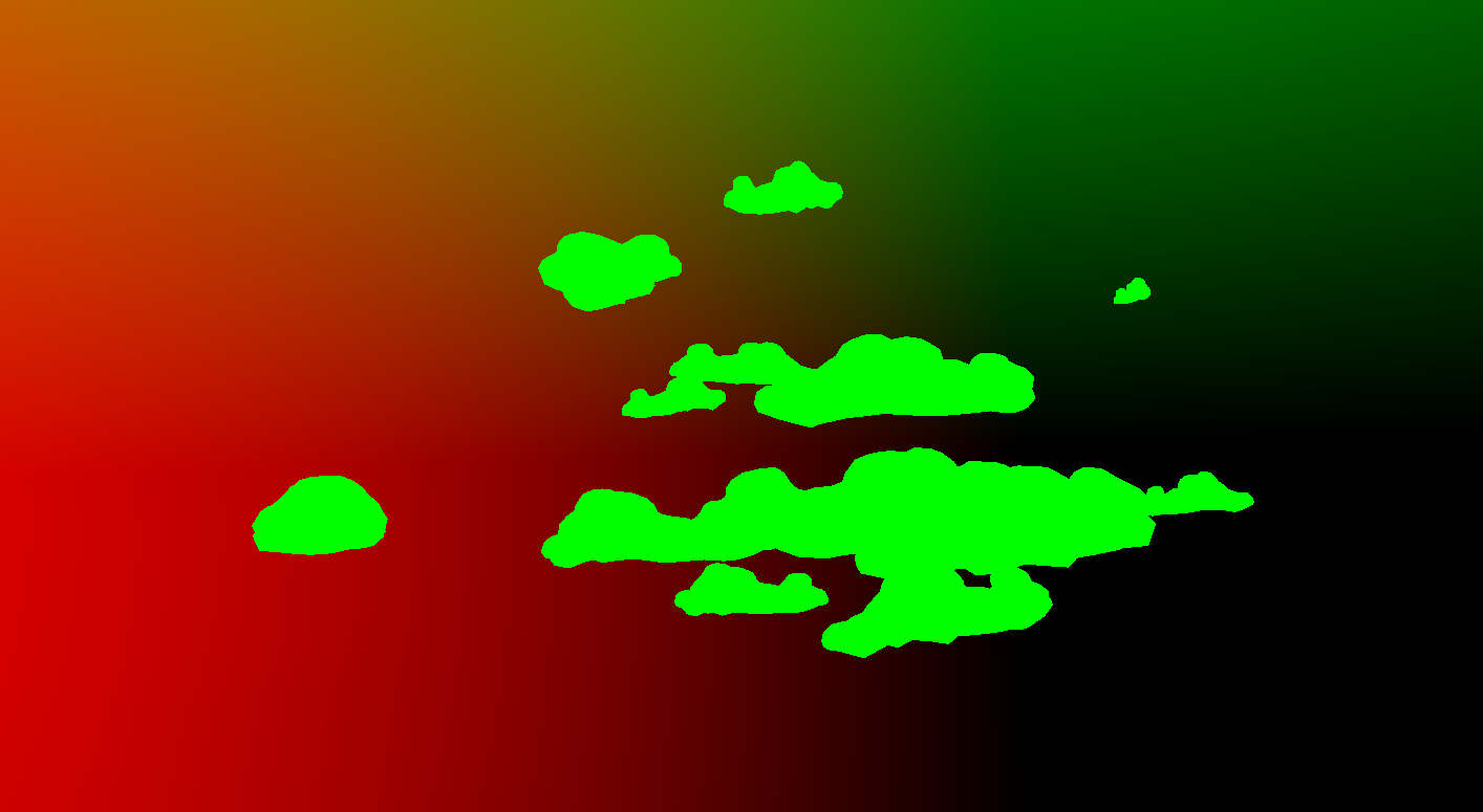
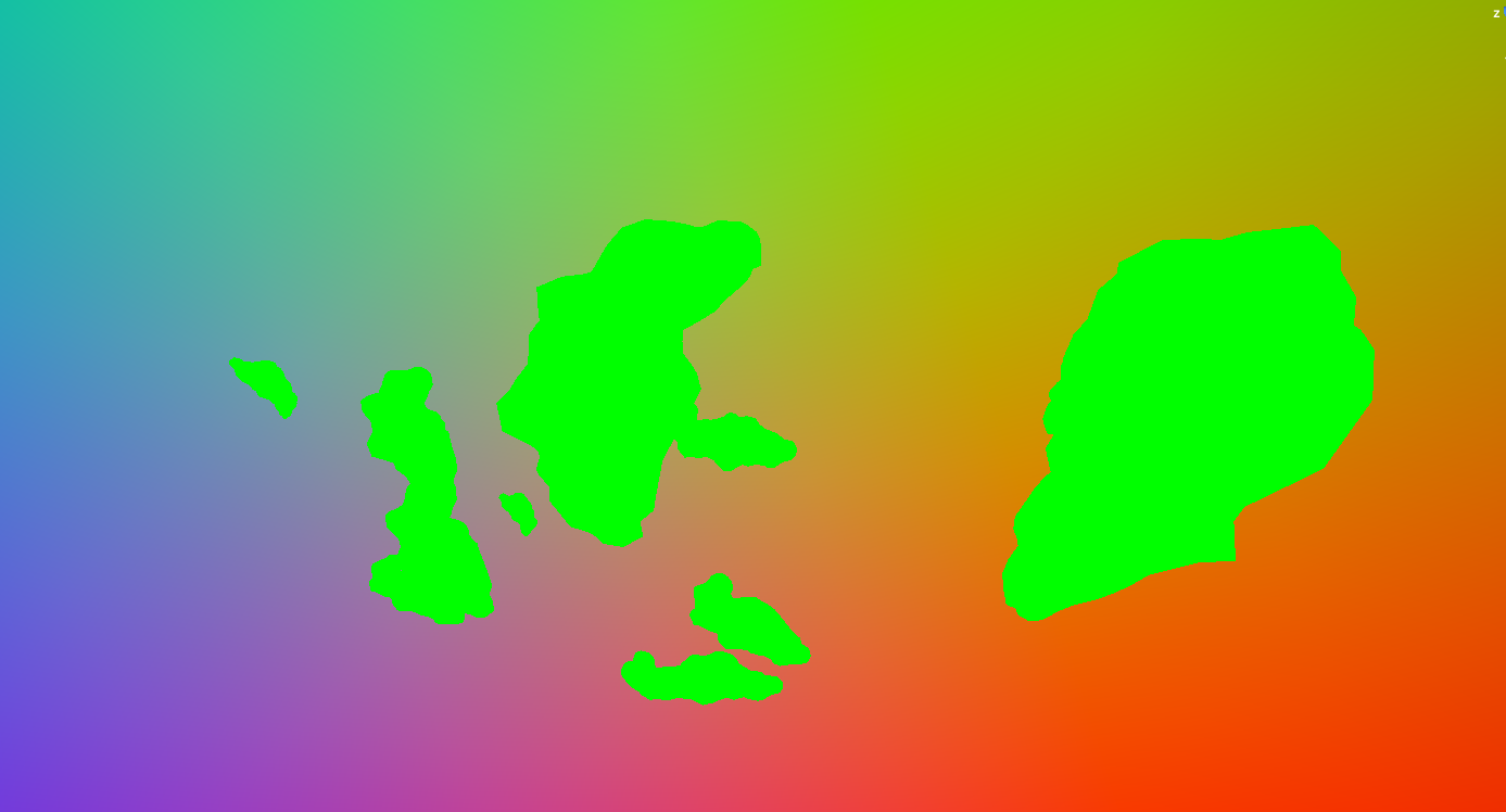
I'm trying to get the world UV coordinates projected on to my surface shader/mesh
So the green should be the colours in the background
the colours in the background are a visualization of world UVs
Nevermind got it fixed
How can I set a property in a shader/material that affects only that one object and not everything that shares a material with it?
@atomic glade You could duplicate the material whilst creating the game object and assign the duplicate as the material of the gameobject. Now you can just modify the material that is on the gameobject and the others will be fine.
@atomic glade If you get a reference to the renderer and call renderer.material at runtime (e.g. in Start(), rather than using .sharedMaterial or a public Material mat) it should create an instance of that material and assign it automatically. You need to destroy the material manually though when you are finished with it (e.g Destroy(renderer.material) in OnDestroy()). Could also use Material Property Blocks which are set per renderer, (unless you are using URP + SRP batcher as I think it breaks the batching so material instances is better in that case).
@worldly steppe Custom shaders won't be upgraded automatically, you'll have to rewrite it manually.
going nuts over here.. getting reports of errors from users.
they're getting D3D shader create error for vertex shader [0x80070057]
a ton of them
varying hardware
NVIDIA GeForce GT 540M, NVIDIA GeForce GT 555M and some Intel Chipsets which well.. probably shouldn't work
but even on a NVIDIA GeForce GTX 1050
not sure if that's the problem, but an older build works.. from before we switched to using the post processing stack (v2)
I have some DXT textures I'm downloading at runtime (created via Compress and loaded with GetRawTextureData/LoadRawTextureData). I could save the width/height somewhere, but am I right in thinking I could look in the byte stream? I tried an example I found, but it's not working. Does Unity create the header info when using Compress?
https://forum.unity.com/threads/loading-crunched-dxt-at-runtime.497861/ - implementation that worked for someone else (not sure how their graphics were originally created)
I just had a poke around in some files... I don't think it saves headers
@wild marlin Do all those cards support DX11? And are the users upgrading their drivers? Otherwise you'll need a DX9 compatible build or set your min standards to DX11. Guessing though. From this:
https://forum.unity.com/threads/d3d-shader-create-error-for-shader-0x80070057-vs_5_0.355433/
See bottom here too: https://github.com/HouraiTeahouse/FantasyCrescendo/issues/127
And https://blogs.unity3d.com/2017/07/10/deprecating-directx-9/
Might want to add a DX11 check of some sort if you don't already.
Guessing, trying to help. Exuding optimism.... 😉
Unity Forum
Hello everyone!
We have recently noticed that our game build crashes on video cards not supporting DX11. We are using Unity 5.2. The error reported is...

GitHub
Fantasy Crescendo Version: Development Build 220 Operating System: Microsoft Windows 7 build 7601 x64 Expected Behavior: http://i.imgur.com/wvbtyo4.png Actual Behavior: http://i.imgur.com/v6uafEZ.p...

Unity Technologies Blog
We will be removing support for DirectX 9 on the Windows platforms; as a result Windows XP will no longer be supported by default.
When will it happen?
U...
The 1050 should though, right? Unless they're running it on some old Win 7 or some damn thing with old drivers
DX11 is supported on like everything from the past decade
I know, that's why unity dropped support for DX9.
But there are people that run old crap, for various reasons, including old drivers.
Like I said, just guessing.
The error seems to be (via a google check) associated with lack of DX11
Even stuff like the GT 4xx series from nvidia has DX11 support
IF THEY INSTALL IT, sure. 😉
not sure if that's the problem, but an older build works.. from before we switched to using the post processing stack (v2)
@wild marlin
A lot of those links indicate PP problems when lacking DX 11, DOF is one.
Oh, replies! 😄 reads
from their DXDiag readouts it seems that they have installed proper support
i'm getting feature levels: 11_0,10_1,10_0,9_3,9_2,9_1
@meager pelican
the post processing stack is using #pragma target 3.0, which should.. be fine, right?
(the uber shader that is)
Well, per this that's DX 9 level so IDK.
https://docs.unity3d.com/Manual/SL-ShaderCompileTargets.html
Of course that's only the shader min level compile code, not a system check in your code.
So IDK. If you're getting 11 out of DX diag, that's not it.
You need a bug report or something with Unity, or unity support.
Got any more info than that one line?
Is it your custom PP shader, or unity's? Which shader? All?
@wild marlin
gotta run, but yea it's like a million shaders... so it seems like something else is off
we found that we were prewarming all the shaders at the start of the game
so that might have been it
megaderp
lol
Exuding optimism here.
I didn't do anything other than spitball.
But I wonder if like DX12 variant tried to pre-warm on DX11 or some dang thing. I wouldn't think it should. I'd be surprised that any not-acceptable variant would try to warm.
But maybe it's something like an out-of-memory or weird thing. Let us know I'm all curious now.
yea that's what i'm thinking too
it tried to warm up aaaaaall variants, even incompatible ones
or something
i'll write if i figure something out 🙂
gotta run now though
time to pick up the kid and some pizzas 🍹
Unity Forum
once I started to prewarm the shaders, I get thousands of these errors, but it happens only on old HW:
D3D shader create error for vertex shader...
;)
You might be on the right track (when you get back). Too bad there's no resolution in that post.
Oh, that's exactly the issue. Such a shame that there was no resolution there, yeah 😛
Unity recommends shader variant collections instead. But if you need a quick-fix, you might just remove that warmup and let the pieces fall where they may. :2c:
Yes, we saw that too. Do you have any experience with working with variant collections? From what we could gather there could be problems with generating collections for devices (eg. Nintendo Switch)?
There we go, I'm on the tram (corona wagon). Yep, looks like we're on the right track indeed.
To hell with prewarming, I say. There might be a minor tiny hickup when loading into levels, but we're not on mobile anymore so that should be fine i think.
(corona wagon)
@wild marlin
Hope Not!
Insert cliches here: "These Times" "Stay Safe" etc. Wishing you the best. We're [mostly] wearing masks now in The States.
No experience with them. Looks interesting though.
Should probably get myself a mask (or 500). Think i have too much beard for them to work though...
Yeah, they don't work well with that. Mostly the masks (unless special) are for reducing particle cloud FROM you to protect OTHERS. So it has to be an "everyone does it" thing. As I understand it. But unless N95 or higher (or whatever your country calls it) it won't filter out the virus aerosol. Watch out for rashes 'n stuff on the kiddies too (Google "Covid Toes").
Hm! Haven't heard of that toe thing before. Cheers.
@meager pelican it worked! woop
I am reading this topic about Unity's editor shader. Tim-C pastes some code for 2 files: SceneViewSelected.cginc AND SceneViewSelected.shader.
How are those two files connected? All the shaders I have seen only use a .shader
Unity Forum
Hi just migrated to Unity 5.5B and everything is working fine and seems stable so far.
I got 1 question about editor selection outline feature. I use...
@visual flower Shader passes can have #include "SceneViewSelected.cginc" which is like copying the entire file into the pass. It allows you to organise things nicer and reuse code in multiple passes.
Hey guys I'm making a simple distortion shader with shadergraph for URP abut I have a problem. The screen position and scene color nodes dont seem to work in VR single pass instanced. Any ideas on how to make them work ?
right, and im an idiot for expecting to see the include at the top, when its in the middle haha
makes sense now, thanks @regal stag
hi, I'm trying to use an unlit shader graph, but when I apply it to an object it just disappears, even though the material's thumbnail display correctly


could someone please help?
The Vertex Position input is expected in Object space
If you put a world space position into it, it's not going to be rendered in the correct place
that's it, thanks so much @regal stag !
I guess this is pretty old and things have changed, and this is way above my level but I figured I would try and test around with it a bit @regal stag .
Unity complains about syntax error
// #0: things that are visible (pass depth). 1 in alpha, 1 in red (SM2.0)
 Pass
 {
  Blend One Zero
  ZTest LEqual
 Cull Off
ZWrite Off
// push towards camera a bit, so that coord mismatch due to dynamic batching is not affecting us
 Offset - 0.02, 0

 CGPROGRAM
 #pragma vertex vert
....```

"Shader error in 'SceneViewSelected': Parse error: syntax error, unexpected '-', expecting TVAL_VARREF or TVAL_NUMBER at line 91"What would be "todays" way to achieve this in Unity?
sorry I forgot to say its the Offset - line
Uh, I'm not sure sorry, maybe someone else knows though
@visual flower Actually, it might be the space. I think it should be Offset -0.02, 0
aight np, thanks :)
Im giving up, modifying this without understanding anything about shaders is impossible lol
Hello guys, I'm making an RTS, and I want a selection circle for units. Is there a simple way to draw a circle on a plane and scale it without it getting thicker and without making a new circle texture for each diameter?
HELP: what does Albedo mean? is it possible that it has no alpha? and what could I use that has alpha?
albedo -> base color of the surface
and check the import settings of the texture you're using
if the texture has values specified for alpha, you can use them for transparency
how can I get this to make the background transparent:
o.Albedo = float4(0, 0, 0, 0);
did you set the 'Tag' to 'Transparent'?
yes
this the sewn together piece of shader that I have pasted together from varios sources
I litteraly have no idea what I am doing
still just black
maybe that part of the code just never runs
try setting it without that if
see if it works
                        if (d > _Radius && d < _Radius + _RadiusWidth)
                        {
                            o.Albedo = _Color;
                            o.Alpha = 0;
                        }
                        else
                        {
                            o.Albedo = float3(0, 0, 0);
                            o.Alpha = 0;
                        }
still black
if your material itself set to transparent?
I don't mean shader now
literally the material
its been ages since I've done shader work on built-in but on SRPs you can set the materials mode to different than what's defined on the shader itself
anyway, how I'd start to decipher that myself is that I'd check some shader that is known to work and see how the shader setup differs for it
I do not know of any "material mode"
also would recommend highly using ASE or even free shader forge unless you really want to write shader code by hand
wonder if the setting was on the mesh renderer instead
nope
could try adding ZWrite Off
you could do
if (d > _Radius && d < _Radius + _RadiusWidth)
{
  discard;
}
Not sure if that works in surface shaders, but it should
I think it's black because you have no blend mode set
I always cheat on these and see what either some stock shader does for these or just use node graph to do same thing and see the generated code
ie: add Blend SrcAlpha OneMinusSrcAlpha to the top of the subshader
that would make sense
you could do
if (d > _Radius && d < _Radius + _RadiusWidth)
{
  discard;
}
Not sure if that works in surface shaders, but it should
@last robin that works
now, the next step is to somehow get the transform model scale inside the shader
to have circles of different sizes depending on the scale of the quad they are rendered on
but all circles with same thickness
any clues?
you want radius to be scaled based on the object size? I suppose you could multiply radius by max(xScale, zScale) assuming they're always going to be flat on the xz plane
the tricky bit is getting those 2 scales
you could set them as a property
or you could pull them from one of the matrices
Are you sizing the quad appropriately already?
oh actually this could probably be done much simplier, if the circle is always in the center of the object anyway, assuming you have uv coordinates you could calculate the float d = distance(float2(0,0), uv);
your radius wouldn't be in world units though if that matters
I don't fully understant
There you go. But it's float2(.5, .5)
ah true
That's where I was going too. 😉
basically try this float d = distance(float2(0.5,0.5), IN.uv);
oh i guess it's uv_MainTex in your case
He'll have to change his width to be a % of the quad size.
oh i guess it's
uv_MainTexin your case
@last robin shader does not have a texture
i'm not a surface shader expert as you can tell
i don't know how that works in surface shaders, but it you could just throw a _MainTex("_", 2D) = "white" {} at the top even if it doesn't have use a texture
The radius would be from 0 to .5 the width would be like .1 or .05 or something.
basically try this
float d = distance(float2(0.5,0.5), IN.uv);
@last robin still this doesn't work
float d = distance(float2(0.5,0.5), IN.uv_MainTex );
and if that doesn't work throw _MainTex("_", 2D) = "white" in the properties section
it might just be zero without any texture idk
You have to fix the ifs. Publish code again so we know where you're at. Too many edits.
float d = distance(float2(0.5,0.5), IN.uv_MainTex );
@last robin
not same thickness now tho
ah hmm
The thickness will be a % of the quad size.
Bigger quad, bigger circle if the % stays the same. So you'll have to scale that based on whatever. But you can pass that in from C#
is there no way inside the shader?
It's all relative. Sure there's probably a way. But how do you define, in human terms, how thick it should be. You have to be able to describe it to code it. So what defines the thickness?
World units?
Object units?
screen space size?
world units
OK, but that will scale with the quad.
World units will NOT scale with the quad.
Oh, edit.
OK
well then that should be possible right?
the whole scaling normaly but the inner thickness using world units
float d = distance(_Center, localPos);
if (d > _Radius && d < _Radius + _RadiusWidth)

float3 xBasis = float3(unity_ObjectToWorld._m00,unity_ObjectToWorld._m10,unity_ObjectToWorld._m20);
float3 zBasis = float3(unity_ObjectToWorld._m02,unity_ObjectToWorld._m12,unity_ObjectToWorld._m22);
float scale = length(cross(xBasis,zBasis));
if (d > _Radius * scale && d < _Radius * scale + _RadiusWidth)
{
  discard;
}
Hi, I'm trying to add #include "Packages/com.unity.render-pipelines.universal/ShaderLibrary/Lighting.hlsl" to a custom node in shader graph, but when i add it it throws Shader error in 'hidden/preview/CustomFunction_6AB1134F': redefinition of '_Time' at /Users/Bri/Test2020/Library/PackageCache/com.unity.render-pipelines.universal@9.0.0-preview.14/ShaderLibrary/UnityInput.hlsl(37) (on d3d11), anyone has met the same proeblem? is there a way to see the actual generated shader ?
that should do it
basically scale the radius by the area of the quad
it's basically grabbing right*xScale and forward*zScale from the matrix
and the cross product gives you a vector with a length of the area of a quadrilateral formed by those two vectors
@jovial onyx right click on the master node and it should give you an option to see the code. But it MIGHT be that it's already included.
@last robin it does scale, way to much
if I scale the quad (which is 1² unity unit big) to more than 1.6 the circle is outside of it
@meager pelican I'm adding that because i need a function from there, and looks it's not imported because i get an not defined error
i'll check that
basicly I'd want the circle to always stay inside the quad, not leaving the edges
when scaling the quad up
I hope you understand what I mean
ah yeah float scale = sqrt(length(cross(xBasis,zBasis)));
I cant seem to find any working "inset"/"inline" outline shaders for Unity, which I find strange. Anyone ever heard of one/seen one recently?
yesh
tho it isn't perfectly at the border of the circle, it scales perfectly
stupid me, I can just adjust the radius in the shader material
now it is, on a radius value of 0.4
it's not at the edge because you've defined the radius width to go beyond the radius
so radius of 1 means the outer right will be > 1
mhh, how could we make it that a radius of 1 does mean it barely touches the edge?
you can change it to if (d > _Radius * scale - _RadiusWidth && d < _Radius * scale) if you want the radius width to be the inside of the _Radius value
yeah, makes sense. well it works perfectly and exactly how i wanted it
@last robin thank you for the help!!!
and there I was close to despair, using a line renderer xD
um, one last thing, how can I make the ring semi transparent?
then use o.Alpha i guess? not sure about what you do in surface shaders
but that basically enables alpha blending
ie: add
Blend SrcAlpha OneMinusSrcAlphato the top of the subshader
@last robin that is already there, and was when you wrote it
still doesn't draw alpha
bah too long
well you need ZWrite Off too
not sure if that's the enough to fix it though
also maybe try #pragma surface surf Standard fullforwardshadows alpha:blend
looks like that might be how surface shaders do it?
yea
but now its lit
and since it's a part of UI of sorts, I need it to be Unlit
ignoring all stuff with light and shadows
so i want to make a kind of laser beam for my character
and btw its in 3rd person
ive been using shadergraph, with a linerenderer, but the texture looks flat
is there a way to curve it somehow so it looks more cylindrical
or should i instead try to procedurally generate a mesh
@shy spruce what do you mean to "curve"
They're probably (ideally) looking for a volumetric-ish laser beam...cylindrical.
Line renderer does flat stuffis.
I'm using GetMainLight() hlsl code, but the color is always set to black even on a scene with a sunlight, anyone knows why?
You can A) Use a particle system type of thing B) use multiple lines in a funky pattern instead (I've done that with like 3 narrow line renderers offset with sin waves 'n stuff) C) research volumetric rendering (but you won't be happy), D) use a cylinder
What makes most any of it look "round" is lighting/shading.
Using Cylinders and a shader with color by normals should be fine i think
Ok thanks!!
@jovial onyx What pipeline/shader. Is it URP by chance?
yes
Unity Forum
I trying to create my shader graph node that returns Light Information. For now i using the example from here...
It's URP, i really don't know if i have to set up that th direction light is the main light for the scene
the shader is now compiling
it's not that problem
Well, since it's called GetMainLight() I'm kind of betting you do.
Maybe check that the Main Light is enabled in the pipeline asset
I think the main light is the "Sun" source in the Lighting tab too. Although if it's not set, it should just use the brightest directional light available.
how would I achieve this? the red shader isnt even needed, i just want to make some materials appear in front of others as if they were in front of them
#if SHADERGRAPH_PREVIEW
    Direction = half3(0.5, 0.5, 0);
    Color = 1;
#else
    Light light = GetMainLight();
    Direction = light.direction;
    Color = light.color;
#endif```From

Unity Technologies Blog
With the release of Unity Editor 2019.1, the Shader Graph package officially came out of preview! Now, in 2019.2, we’re bringing even more features and fun...
Yes i'm using that exact tutorial
void SceneLight_float(out float3 Direction, out float3 Color) {
  #ifndef UNIVERSAL_LIGHTING_INCLUDED
    Direction = float3(0.5, 0, 0);
    Color = float3(1, 0, 0);
  #elif defined(SHADERGRAPH_PREVIEW)
    Direction = float3(0, 0.5, 0);
    Color = float3(0, 1, 0);
  #else
    Direction = GetMainLight().direction;
    Color = GetMainLight().color;
  #endif
}
using that because it doesn't compile the original code
Found it
It was on the URP Asset inspector
My fault, it was on disabled because i assume i messed up some days ago when i was testing everything
Thanks @meager pelican and @regal stag ❤️
If I multiply it for a color I wont get a preview (I cant see the sprite if I use it).
@worldly steppe Custom shaders won't be upgraded automatically, you'll have to rewrite it manually.
@regal stag Ah I see, I tried rewriting it on a new standard surface shader file and I have the same error. Is there a specific shader type that I have to use? Also is there a starting standard shader template for the URP that I can use?
I've been trying to get the toon effect from this video: https://www.youtube.com/watch?v=joG_tmXUX4M to work for URP as it only works for LWRP atm. I went through and changed all (i think) the LWRP references to URP in the shaders and scripts, which got rid of all the errors and the materials stopped being the error texture (purple) but now I don't know what to do. I went through all the Data files (custom srp files) and checked they were all correct, but still nothing is changing. And yes, I have definitly applied the main SRP setting to the Graphics tab in settings. What would I do next?

Download the full example here: https://ole.unity.com/toonoutline
Just the two shaders alone: https://ole.unity.com/toonoutlineshadersonly
Hi everyone 👋🏻 Do you have any ideas on how to implement similar shader effect to simulate welding? https://drive.google.com/file/d/1Odl6cgK9wCtnjBBd81JOQHxl1YMNWBdf/view?usp=drivesdk, please note that the color is changed with time and wave pattern is also created dynamically. Thanks for help in advance!

Google Drive
Here are some more pictures to get the idea 👨🏭
@grand jolt Check the alpha of your colour, it's set to 0 so the resulting sprite is fully transparent.
@worldly steppe Sadly URP doesn't have any support for surface shaders, you have to write vert/frag ones instead (with a few differences like using HLSLPROGRAM/ENDHLSL instead of CGPROGRAM/ENDCG and include URP's ShaderLibrary files & functions rather than UnityCG.cginc ones).
There's some nice examples here : https://github.com/phi-lira/UniversalShaderExamples and a nicely commented PBR example : https://gist.github.com/phi-lira/225cd7c5e8545be602dca4eb5ed111ba
You can also use Shader Graph to create a shader instead, and can even use it to generate code which you could edit later if you need to tweak something that shader graph can't do.
@distant pawn I think the example project here has been updated for URP. You might be able to use that instead or use it to compare to see what's wrong. https://github.com/Unity-Technologies/UniversalRenderingExamples/tree/master/Assets/_CompletedDemos/ToonOutlinePostprocessCompleted
@quaint tree Well, since what you're doing is "filling it in with a material" that implies that you're going to ADD some meshes or distort the exiting one.
You didn't include any details as to what pipeline or hardware you want to run on.
I can think of several general approaches:
- Adding meshes that intersect/overlap...like mesh particle "blobs" placed somewhat randomly. Depends on how "permanent" you need it to be, or if it's some temp effect like a quick animation that you can later swap out for a "canned mesh" or something.
- A canned mesh that you truncate somehow or maybe procedural mesh, tessellated if you can, that you build dynamically.
- A "flat" plane that you treat like water, but it's not moving in waves except at the weld-point...it's opaque silverish/color-distored water. Masked off as to "filled vs not-filled". So check water shaders. Again, tessellation would help you get the details in place particularly at the edges.
- some form of volumetric metal, like you'd do for any liquid (ugh).
- distortion of the original mesh, like vertex distortion, maybe combined with a mask/map of some sort to indicate surface type and coloring differences.
/spitballing
P.S.
Are you building terminators? General rule of thumb is "Don't build terminators." 😉
@distant pawn That video is for a post-processing effect that is a "posterize" I think with outline. Is that what you're doing?
@meager pelican Thanks for the detailed answer! The goal is to run it with ARFoundation on iOS and Android as the reference application works like, for now my plan was to go with approach #3 of the flat plane, but in case of mobiles tessellation is not really an option, so that leaves us with texture effects.
The interesting thing is that depending on the movements (speed and shaking) of the nozzle waves are generated accordingly, so it’s not some predefined sin (whatever trigonometric function) pattern of waves...
P.S. We are building just normal robots 🤖
Can you support compute shaders on your mobile target?
heya im a bit confused. i want to use an additive particle shader however there isnt one for HDRP. does anyone know what i can do?
User shader graph with transparent master with an add node in the mix?
is that a reply to me? if so ill check that out
Yeah. 🙂
Isn't there an additive blending mode option on the HDRP Particle shader? I think the URP one does.
@quaint tree You can always calc some texture-stuff on the C# side too if you need to and/or can't support compute shaders
You'd think there would be Cyan. IDK HDRP off the top of my head though. But additive is additive....
Maybe they just change some blend mode.
Metal has got limited support of compute shaders as far as I know
@meager pelican to be honest i have no idea what you meant. is there a tutorial for this somewhere? i cant seem to add a transparent master, the default is lit master
i just check the pinned... found tutorials
Yeah, there's a "gear" that let's you set queue options, like transparent queue.