#archived-shaders
1 messages · Page 151 of 1
There is a define for the analysis phase in surface shaders. Lemme go find it.
You could use that to "force" it being used, it's just a "pass" of the shader somehow. That would make it think it's used and then omit it later. But since you won't reference later, IDK why you even care. But hang on. I'm digging this up out of the dim recesses of obscure memory on a different semi-related issue.
Here's the message I got back on a bug report on a sort-of similar issue regarding the filling in of WorldPos variable on the input structure (it was optimized away with certain user-defined conditional compilations).
To solve your issue, you will need to force output values to be written or inputs used at least during the shader analysis pass and can do so by checking against 'SHADER_TARGET_SURFACE_ANALYSIS' define. In the supplied example that would be by adding "|| defined(SHADER_TARGET_SURFACE_ANALYSIS)" with the other checks
@grand jolt
In my case I WAS using it in certain conditional compilation situations, but not others. And the analysis phase didn't have defines where it was used, so it optimized it away and produced the wrong code.
hmm
Would it work for unlit shaders also?
Before you wonder why I would want all declared stuff to be passed by Unity, I'm doing some experiments with the native shader compiling API
I got the impression that was for surface shaders. YMMV
Discovered some interesting stuff with your define tho
Unity uses MojoShader to parse the shader
I mean, at least, the DX part
Yeah, they tell you that here:
https://docs.unity3d.com/Manual/SL-ShadingLanguage.html
but again, Surface Shader.

I'm a bit ignorant on the subject as I was thinking CG was the same thing as HLSL
They share a lot of similarities, tho
They do.
And some irritating differences.
And one of them should just die already. 😉 :p
Or maybe both, and everyone go Vulkan with some new standardized language.
Actually, I think NVIDIA has said CG is pretty much dead.
Is there an easy way to convert from RGB to HSV/HSL and back in shader graph?
Probably could with a custom code node but might be easier to just convert in C# then pass in to the material.
Managed to put something together in the shader, ultimately. If the question comes up again for future reference, I made custom nodes using these two functions: https://forum.unity.com/threads/different-blending-modes-like-add-screen-overlay-changing-hue-tint.62507/#post-413037
Unity Forum
Hello everyone,
I'm currently making my first Unity game for my Game Design class and thus learning the ropes with JavaScript, the engine and now...
Unity Forum
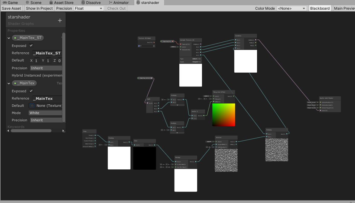
I wrote a shader graph to make some effect on a transparent layer.
[IMG]
Previously I adapted it to work with the transparent shader default. By...
I'd really appreciate anyone taking a look at this!
I've been trying to research it since I posted the topic but really tough ...
@frail salmon so you have a background image / texture which you want to overlay a starry sky effect?
no
I have a background and 9 star layers being animated in parallax with another seperate alpha mask layer applying to every part of the overall background
the star layers use the alpha mask plugins shader
for that plugin to function
but I want to add some effects in my own shader
the stars are in a large texture2ds
The system used to animate in parallax is extensing some variables of unlit/transparent, I modified both my shadergraph and the plugins shader to work with those (maintex_st and etc) but Im lost on how to combine my shadergeaph with their shader
generally it's complicated unless they have exposed it for you to use, it will mean delving into the code.
you could always try to recreate the plugin in shader graph, which would then give you full control. Depends how complex the effect is and how much time you have 😉
nowhere near enough
im totally willing to pay someone to do this haha since shader expertise seems hard to find
well i am just curious maybe you can point me in the right direction
i just couldnt even google for stuff about this kind of problem
i dot mind to recreate my shader in code either if thats a better solution
or i just couldnt find like, how would I learn what variable to look for in the code, etc
I guess its _AlphaTex mainly?
Maybe what I am asking fundamentally does not make sense. Since previously I was using the variables of default shaders. And now I am trying to combine these two shaders? Is that even possible haha
@frail salmon No, the concept of combining shaders is not a thing, except just creating a new shader that does both.
@frail salmon it perhaps depends on what your end result is your trying to achieve. Could be your trying to over think it, I know I've made that mistake. Might be something to park for now as a "nice to have" and re-visit when more of the game is complete.
Hey guys, can you use a PBR graph and VFX Shader Graph with the URP 2D renderer? I'd just like to know before starting to learn about it
Hi anyone knows if theres a way to apply a shader to a group of objects with different materials? The aim is to create an outline for a composite object
A shader is a material, a material is a shader.
So you have to have all the composite materials be aware of what's going on, and then maybe use another pass/post-process to do the outline. Think stencil outline or something.
Is there any easy way to change all the materials on a mesh to one thing then switch them back, at runtime? I want to make a prefab semi-transparent then switch it back again
Changing one material is easy, but I’m not sure how to change multiple ones then change them back, without even knowing what materials they are (cos the object might change etc, and some meshes have 2 mats, some have 8, some 1 etc)
have a script which collects the data per object, then you can have it collect or replace on demand.
But sounds a little crazy, why does pre-fab need to be semi-transparent?
Sorry, I meant an instantion of the prefab
I’m doing a building-block thing. So before the player “places” a block, it appears near the mouse cursor as a semi transparent hull
ah gotcha
Then when they click in a suitable location the object textures change to opaque, I turn on the collider for it and spawn a new “hull”
That works fine for my test block which has only one mat but some blocks have 10+ materials
And I won’t know ahead of time what the object they’re placing is etc until they pick it and rewriting the code for every single block doesn’t seem fun (could have upwards of 60 different blocks here!)
10 materials on one mesh sounds a little much too or is that one prefab with 10 different meshes?
Several materials, sometimes several meshes etc (like one block is an engine part so it has exhausts, cables, textured pipes etc etc)
but essentially, you should be able to assign a script at top level of your prefab which iterates over the child objects, collecting data which you can save into a list probably using a custom class for ease. make some public functions which trigger the swap from transparent to normal mats.
Ah so like collect all the mats into an array
are all the mats using standard Unity shader?
Yeah.
you could swap the mats to transparent and change the opacity that way and swap back to opaque... but that's assuming they are all opaque to start with
So collect mats into array, then assign transparent mat to the entire prefab then when time to switch back, drop the array back on it
Doesn’t the transparent mat use more overheard than opaque
Plus some will be transparent or not (window blocks, the glass is trans the frame is not etc etc)
then yea you need to feed it into arrays, do swap and back again
Ok thanks.
once you have it all setup will be simple, just consider each problem when making your data arrays
I’ll have a look thru the refs for the call to return all the mats on an object
(I know, actually looking up the reference instead of just asking! Letting the discord down here 🤣🤣)
mats on an object should already be an array so it saves you a little, just need a simple class to store object against material array... I think 😉
Yep, I just looked it up renderer.materials returns a Material []materials array.
Thanks again @thick fulcrum
I'm not sure if this is the correct channel to ask this but I've got a problem with my Compute Shader. I was using some example for Metaball shader in a Unity version before URP/LWRP. It was working perfectly there but when I upgraded the project to URP/LWRP it had it's issues which I solved. But I've got one more step that's problematic now and that's my render texture is only showing the my Metaballs and the rest is black (there's no skybox).
So my question is really, how can I apply alpha on the render texture through Compute shaders? I believe that doing that will solve "everything" for me, it feels like that's the last step.
I can make my Shadergraph transparent when using Unlit Master, but when trying it with HDRP/Unlit
I can't get it to be transparent
\
Picture #1 and #2 are with regular Unlit
Picture #3 and #4 are with HDRP/Unlit
Input to Color ans Alpha are identical to both - what am I doing wrong here?
Hey guys, can you use a PBR graph and VFX Shader Graph with the URP 2D renderer? Or do you HAVE to use 2D renderer shader graph? I'd just like to know before starting to learn about it
Hi i am making a fire with particle system, but when i try to add texture there is no additive shader, there are only standard surface and standard unlit. How to add Particle additive?
Hi, how can I send in a RenderTexture Depth buffer to a compute shader?
computeShader.SetBuffer("depth", renderTexture.depthBuffer);
doesn't works as depthBuffer is a RenderBuffer instead of ComputeBuffer
To be clear I only need to read the depth buffer

GitHub
Purpose of this PR
Problem
Currently, the master node definition is too rigid and defined via leaky abstractions. This gives the the following problems:
Large list of individual master nodes. Chan...

Hi!
Did someone know how many uv channels unity support? I was reading post saying that only 2 uv channels are supported, is that still true?
I'm trying to understand urp setting. Even after reading the docs I don't understand the use case of having depth texture enabled. Can someone explain in layman terms please/
Is depth texture related to stencil buffer? Because I have some stencil effect going on
The Depth Texture option is required if you want the Scene Depth node to work.
What exactly is scene depth? I don't have any depth of field blur post processing effect
When used in a transparent shader it allows you to obtain the depth of objects in the scene.
aka how far objects are from the camera
Ahhh ok that makes sence
I understand about transparent shaders. Used them before when playing with shader. So basically if I disable it, transparency will be broken right?
next question:
Been trying to figure out my game resolution in the editor but I have no idea what it is. All I know it I'm on 16x9.
Please correct me if I'm wrong. If I set the slider to 0.5. My mobile device's native resolution is 1920x1080, the game will be rendered at half the resolution at 1280x720 and upscaled to fit the screen, right?
I think only opaque objects show up in the Depth Texture, since they have ZWRITE enabled. When using Scene Depth node, you usually want to get the depth of scene objects behind the object the shader is applied to. If it's not transparent, you'll just be getting the depth of the shader object instead.
@regal stag I understand now
https://github.com/Unity-Technologies/Graphics/pull/344
I'd have so much to say about the initial versions UX....
GitHub
Purpose of this PR
Problem
Currently, the master node definition is too rigid and defined via leaky abstractions. This gives the the following problems:
Large list of individual master nodes. Chan...
for example, it's a major PITA to even be able to select individual nodes on the master node as it just keeps picking these things instead:
I'm guessing the idea here is that you can insert extra node to the middle but the hotspot for this is like 50% too big
for the context, my mouse is hovering already on top of the existing nodes text and it still picks the middle bar instead, making it pain to even get the actual node selected
@still orbit ^
also there's this typical spacing issue which seems to plague SGs in general:
I do dig the new setup in general though
I do assume that a lot of users will be confused by the ability to add nodes that are not supported by the selected material type (there could be some toggle to hide them, especially if they are unconnected)
Hey, understood about those two issues
ill try to investigate reducing the size of the selector for the separator doodad
But do you have this problem in VFX? It should be the same...
We are looking into better label scaling for the inspector atm
as for inactive blocks, youre seeing them greyed out right? and in preferences theres an option to auto add/remove blocks to always have only the ones that affect the current shader
@still orbit tbh, I haven't tested vfx as I haven't used it even before this 🙂
ah, I'll look into preferences
I do kinda feel the toggle should be in the SG editor instead
I'm curious though, are the material types still going to be "hardcoded" for internally defined master graph types or does this new setup finally let people implement custom material / SG types from their own projects?
the auto add/remove setting isn't saved per-graph, which is the main reason why it isn't in the SG editor
it's a project wide preference for all SGs you may be using at any time
so the inspector and blackboard toggles are saved per graph?
(I've never paid attention to that)
you can have different graphs with different states of blackboard/inspector toggled on and off open at once
but the auto add/remove blocks right now is universal for all open editor windows or any you might open
why you wouldn't want that to be shader specific setting tho?
or is there some technical reason why it can't be so?
I can imagine that people could want to use that based per case
meanwhile, I'm trying to exploit this new setup now for CRT again 😄
since I know CRT works with URP unlit, with this new setup I can actually force SG to only save the shader that writes to crt to use only universal, despite the rendering is done for HDRP
is the material types still going to be "hardcoded" for internally defined master graph types or does this new setup finally let people implement custom material / SG types from their own projects?
This is a step towards this, but we arent there yet
what this lets us do is generate shaders with an arbitrary surface/vertex description
so each RP can have whatever data it wants from the graph, and that graph is usable between all of them
what's the main motivation behind that? like help asset store vendors or just for easier crossplatform deploy?
both of those lol
plus us, as managing 9 master nodes was a headache
tonnes of code duplication
I'd love to be able to swap easier between urp and hdrp at runtime but I doubt that's ever going to be officially supported
it kinda works even today
of course this change will help that sort of hacks still as it's now super easy to author the shaders at once for both
Hello there !
I have a problem my shader graph shader tell me that :
https://cdn.discordapp.com/attachments/381062572088229898/705854113568653362/unknown.png
Here is the graph. I have it working fine with pure HLSL for shader 3.5... Any idea ?

I have question about this new stack setup though, is there any way in this now to view the generated shader code?
in old setup you'd just right click on the master node but that's gone now
oh wait, nevermind, it's in the inspector now when you select the SG on project browser
it took me a while to even figure out how to deal with the new inspector, was like wtf how do I get the inspector to show the options even (as got so used to that blackboard panel not being that important in past)
but it's not that unlogical after you get used to it
@still orbit @stone sandal just to be clear, I wasn't really wondering the auto add/remove option (altho I think it still failed to remove some nodes when I tested it), I was more like wondering if there could be some option to hide (not remove) the nodes not supported by currently selected material type
right now I can like for example add dielectric node for HDRP Lit material but its obviously going to be grayed out as it's not supported by that type
this bloats the node selection list with tons of nodes which user will never know while browsing the list alone if they are compatible or not
altho there probably aren't additional nodes you can even add beyond the nodes that are given to you automatically...
do you mean in the create node menu?
oh that is completely different
the add/remove is only for the blocks in the stack on the graph itself, when you change target settings etc
there isn't anything to filter the create node menu yet
yeah, I noticed what it was for when I tried it finally 🙂
there will be, but that's not what that preference is for
is there any estimate which SRPs this PR is supposed to land atm?
I'm guessing 9.x
we're trying to get it landed very soon
is it something that will get backported to 8.x?
I don't see it going back to 7.x
no, 9.x.x-preview is the current package version of master
when it lands it will be published in the next auto release of the preview version that passes tests
but i can't say if the 9.x verison will definitively be what actually ships as the public verified version
mainly trying to estimate if this is going to land on 2020 still
oh it will land for 20.2
ah, cool 🙂
just no way to say for sure what SRP version that would correspond to at this point
I'm already testing on a9
yeah, not looking for specific versions as I know that's not something you can even tell at this point
(and before it's merged there's really no guarantees anyway)
anyway, I dig it
even if you don't use the additional funtionality, its still easier to set the shader parameters vs from the old master node dropdown
one thing that could be nicer on the node addition thing would be if you could actually gray out or hide the nodes that are already in
right now you can see them listed like all other nodes but trying to add them doesn't do anything (nor it should as they are already there)
this is all in the create node menu i'm assuming
yes
improving the UX of that is entirely separate haha
it's a fully different code package that we use
Hello, would anyone have any idea on how to create a forcefield effect using 2D shader graph? there's a bunch of 3d tutorials out there but none for 2D.
i've tried multiplying a fresnel effect node by the alpha of a texture, but it just seems to change the opacity of the entire sprite equally
i'd like the edges of the sprite to be visible while the inside invisible, similar to how the fresnel looks like
Is there a way for me to detect in a shader which pipeline is being used?
@boreal maple Fresnel calculation is based on the normal. A sprite is flat. So unless it has a normal map, fresnel will look as a constant value.
@devout quarry Maybe using a custom function node and check for defines specific to one or the other RP.
Not sure though.
what are you trying to check with that information, @devout quarry ?
So in a custom function node in shadergraph, I use the GetMainLight() function
but I only want this to compile when the user is using the universal render pipeline
Using my .asmdef I did define a flag I can check so I could do like #if defined(UNIVERSAL_RENDERER)
but that flag will be true when the URP is installed, not necessarily when it is being used
so in my shader I want to use the GetMainLight function only when the active renderer is a URP one
So like Remy said, I am checking for defines specific to the RP, but in a project where I have both URP and HDRP installed, the GetMainLight() function would still be called (resulting in a console error) even if I'm using HDRP as my active renderer, just because URP package was installed and the flag was set to true
I can check in a C# script if the active renderer is HDRP or URP though, maybe I should do that and then set a global shader keyword that I can use in the shader?
i would use that approach right now
hmmm, I wonder if CRT support is just broken in 2020.2.0a9 atm
I saw they had this on the final release notes: Graphics: Fix an issue where in some cases, Custom Render Textures would not be rendered (generally with asset bundles or in a standalone build)
I can get the CRT working just fine in the editor but it does nothing on actual build
@stone sandal Could Shader Graph generated shaders include a #define for each pass in a future update (assuming that it generates passes for both URP and HDRP), like how surface shaders do with these?
UNITY_PASS_FORWARDBASE
UNITY_PASS_FORWARDADD
UNITY_PASS_DEFERRED
UNITY_PASS_SHADOWCASTER
UNITY_PASS_PREPASSBASE
UNITY_PASS_PREPASSFINAL
I've also made sure the shader driving it is included on final build
Alright thanks Spara, I'll test that out.
shader graph already generates defines per pass ?
it's different for each pipeline though but if you check the generated shader code you'll see SHADERPASS defines for things like forward, depth, etc
Ah, it's in include files, like UNIVERSAL_FORWARD_LIT_PASS_INCLUDED is defined in LitForwardPass.
So that's another alternative, right? I guess you might have to include a couple of defines to encompass a whole SRP.
Is that an answer for me?
Yeah, related to your question
These are all the URP pass defines I could find
UNIVERSAL_FORWARD_LIT_PASS_INCLUDED probably being the most common
Rider
i would be careful with those, i think that shader graph uses its own set of pass defines
Hmm, would those define strings be somewhere in the Shader Graph package source?
At least these are the only strings in Shader Graph 7.3.1 that match PASS (case sensitive) that I could find.
it would be in the universal package, but using the SHADERPASS format
Yeah you're right. I thought I was looking at a generated Shader Graph shader with #include "LitForwardPass.hlsl", but I must have seen that somewhere else. Looks like it's just SHADERPASS_FORWARD and SHADERPASS_UNLIT on URP, not including the other extra passes.
@devout quarry But you should be able to do #ifdef UNIVERSAL_LIGHTING_INCLUDED before using GetMainLight, because that's a define that comes with Lighting.hlsl where GetMainLight is defined.
Hey everyone. Wondering if someone could point me in the right direction with HDRP and a post processing shader combination I'm trying to port from Unreal. I'm trying to make a single-pass outline effect that supports multiple (up to 4) overlapping colors. In the original version I got away with this by using the stencil buffer as a bitmask (0x1 for yellow, 0x2 for blue, 0x4 for red, 0x8 for purple, etc.) and then post-processing that buffer using those bits, looked like this (note the additive 0x3 value where the two overlap):
Any thoughts on how I might accomplish something similar in Unity/HDRP?
At a high level I'm thinking that I need to specify what color the object is on in the (overridden?) surface shader for the object, render it to some buffer as a set of bit flags (preferably as a small uint8 buffer if possible), and then read that buffer of bit flags to render the final outline effect somewhere in a fullscreen post-process step. The biggest question I have is how to make this bitmask-like buffer to then read in post-processing.
if you need stencil, it's bit tricky on HDRP
first of all,how many bits you can use is limited by your HDRP version
It doesn't necessarily need to be stencil. I sorta exploited it in Unreal but it doesn't have to be that way.
Basically I need a single buffer where I can use bitmasks to have each pixel contain "ID" information for the objects there.
btw,you know the outline effect from https://github.com/alelievr/HDRP-Custom-Passes/ ?
GitHub
A bunch of custom passes made for HDRP. Contribute to alelievr/HDRP-Custom-Passes development by creating an account on GitHub.
I've looked at them but they collect the source buffer differently from how I need to.
Once I have the ID buffer the rest isn't too tricky, but the part I'm missing knowledge on in HDRP is how to make that bitmask-style buffer I showed above.
I guess an alternative question would be, when overriding a shader/material to render to a custom buffer, is there any way for that shader to read some preset flag or value from the GameObject it's overriding, or select from materials already in the world with their own instances/configurations?
Hm, looking like MaterialPropertyBlock could possibly help, if I could feed that into a replacement shader.
Hey guys, I have a vert shader that billboards a Quad. But It also works in the editor, I wonder if theres a way to make a shader only work in game
is this in URP @soft harness ?
I Don't know. Is URP the one that is selected by default when you make a new 3D project?
depends, there's option for standard, universal and HDRP... so which did you choose? 😉
ok standard
ah ok, yea I'm no code guru.. I understand the principles but it's all greek to me afraid 😉
Do you know a fix?
at a glance the code looks ok, does the problem change on distance or always present?
it's a strange one, could be shadow and lighting related. it's almost like the draw order is wrong.
perhaps try either disabling shadows or handling them similar to this old forum thread
https://answers.unity.com/questions/973067/using-shadow-texture-to-recieve-shadows-on-grass.html
Unity is the ultimate game development platform. Use Unity to build high-quality 3D and 2D games, deploy them across mobile, desktop, VR/AR, consoles or the Web, and connect with loyal and enthusiastic players and customers.
ofc you could just compare your shader with the unity grass shader and try to work out the problem that way.
@soft harness That looks like a pretty standard Surface shader, like maybe the default generated one, but titled "grass".
Most grass shaders use an alpha cutoff. I also suspect that the outline we see is part of the texture, and that you're just using alpha blending.
Anyway, once you get to a certain distance it's going to screw up by "merging" all the outlines into the nearby pixels. Check your sampler/texture settings too.
IIRC, Most grass shaders use alpha-cutoff in the opaque queue. That will write to the depth buffer and do depth testing. Google "unity surface shader grass" or something. Use alpha clipping. Or search for "alpha to coverage".
how do i use Clip? I'm just getting a fulling transperant shader
I got it working! kinda
i'm getting this issue
it's not getting shaded
on one side
But it is one the other side
Since you're using a surface shader, see the examples here, abut 3/4 down the page, alpha to coverage:
https://docs.unity3d.com/Manual/SL-Blend.html
Tags { "Queue"="AlphaTest" "RenderType"="TransparentCutout" "IgnoreProjector"="True" }

// inside Pass
AlphaToMask On```@soft harness I'm curious, are you looking to specifically write your own shaders / learn how to etc. or do you just want any grass shader that works?
As there are a few free ones on the net and some better ones on the asset store which would save you time 😉
Both?
then I will gently suggest Alan's site which has some great intro to writing shaders and understanding basic construct.
https://www.alanzucconi.com/2015/06/10/a-gentle-introduction-to-shaders-in-unity3d/
Alternatively you could look to shader graph, which can be easier for beginner's to jump into rather than figuring out shader code. But that depends on your project and it's target if Universal renderer is suitable.

Learn how to wrirte shaders in Unity. Free shader tutorial with examples and source code ready to download.
LWRP doesn't have support for cookies, which is needed for my game
Is there a way to flip the normans based on the viewing direction?
that should fix the lighting issue
often flat grass is billboarded to rotate to face camera, which means the normals should always be in right direction. Is this not suitable for your game?
I have it all in one mesh, since i'm making the map in blender
well yes you can get campos in shader and potentially use some maths to achieve this.
Or you can double the triangles, back to back.
Wouldn't that make z fighting? and double the polygon count?
Hi guys, is ther a wway to offest the blend node (1) with the tilling and offset node (2).
You would want to use the Tiling and Offset node as a UV input, somewhere down the chain.
e.g. into a Sample Texture 2D node, if you are using that
@soft harness
Wouldn't that make z fighting? and double the polygon count?
Not when you do backface culling too. Then the ones pointing the "wrong way" don't show up.
ok
Is that how people normally do grass? what about displacment?
Like I think it was @thick fulcrum already said, usually you use camera-facing quads, scatter them around. There's examples on the net for displacement too. It's based on y-value usually. Sometimes you have to flip the Y on certain platforms. You'll have to google around. I think Bracky's had an example. But there's 10,000 others.
You could use a flipbook too, to change grass patterns by instance, for example.
Yeah, but translate. You're already doing well in getting a start on surface shaders and "real coding". Don't give up!
Not many free lunches, but there's often optimization "tricks".
what about this code? v.normal *= dot (normalize (viewDir), v.normal) > 0 ? 1 : -1;
How would i implement that?
     float3 worldPos = mul (_Object2World, v.vertex);
     float3 worldNorm = UnityObjectToWorldNormal (v.normal);
     float3 viewDir = worldPos - _WorldSpaceCameraPos;
     v.normal *= dot (viewDir, worldNorm) > 0 ? -1 : 1;
}``` The full thing, i found on unity answersIIRC flipping a normal is only the green component, but that might only be for normal maps not actual 3D normals in whatever-space.
Where do i put it?
NM, I messed up. Editing.
If you're flipping it, I'd think you'd want to flip it before you cacl the worldNorm.
But that's an example from a vert/frag shader. And you're doing a Surface shader.
Can you do something similar with a surface shder?
Yeah, I'm looking it up for you
Thanks!
OK, so you can use a vert function in a Surface shader. This is for a Lambert lighting model, but you see the end of this line?
#pragma surface surf Lambert vertex:vert
so that tells it to call the vertext function named "vert". Then you supply it in the code.
See the example here (But don't use that exact code, use the one you found). Try it and see if it works, I'm not even running unity right now to test anything.
https://gist.github.com/AdrianaVecc/20ae99182d89848086e95cbb6ed523e2

Gist
A shader to invert a sphere's normals in Unity in order to see it from inside out. Useful to create a 360 video player - FlippingNormals.shader
Full Foward Shadows
Standard, probably. With full f s.
but that doesn't matter. What matters is the "vertex:name" syntax.
It works!
🙂
What happens if you move line 48 up to before what is now 46?
pardon?
Move your normal flip to before calcing the worldNormal.
Like this?
            float3 worldPos = mul(unity_ObjectToWorld, v.vertex);
_WorldSpaceCameraPos;
            v.normal *= dot(viewDir, worldNorm) > 0 ? -1 : 1;
            float3 worldNorm = UnityObjectToWorldNormal(v.normal);
IDK why formatting didn't work, but anyway, worldNorm uses v.normal so you have to flip it before calcing that.
Oh frack. you have to do both.
Sec.
It's a catch 22. I'm sure there's ways, but just skip it for now.
Hang on.
It can be done by breaking out the 1:-1 into a variable and multiplying both normal and world normal by that result. But never mind for now.
What values for alpha are you using for the opaque parts. 1?
It would be in your texture.
OK, you're z-writing, and you've got fully opaque color blending.
So IDK about AO and why it's showing up, but someone else might. IDK if it is at all related to the normal or not. Don't want to make you jump through any more hoops. So someone else may know.
We've got you started anyway.
yeah, we got a good start
Now how let's do something a bit easier(?) can we make it sway?
You can!
There's several ways. Most are vertex displacement in that vert() function. You offset the TOP verts. you get that by calcing the worldspace height - some ground-base level. And based on that height, you offset more or less. So it "sways".
You'll have to have some fun googling for it. There's 1000 examples, since Surface Shaders have been around for a while. There's no need for me to walk you through it, and you'll want to look at the various ways and decide for yourself. That's part of the fun. 😉
also i think i know what is happening, becuase the shadows are infornt too.
I suppose it could be the normals thing.
IDK
You could break out the direction flip calc
void vert(inout appdata_full v) {
float3 worldPos = mul(unity_ObjectToWorld, v.vertex);
float3 worldNorm = UnityObjectToWorldNormal(v.normal);
float3 viewDir = worldPos - _WorldSpaceCameraPos;
float flipDir = dot(viewDir, worldNorm) > 0 ? -1 : 1;
v.normal *= flipDir;
worldNorm *= flipDir;
MIGHT do something. IDK.
Nah, sorry
It seems like flipping normals is always a PITA
I'm close to the grass swaying tho
the grass sway is kinda working, it's just the the roots are moving and the tips are not
Oh wait, you're not even saving worldnormal. lol
v.vertex.x += sin(2 * _Time*5) * 5 * (v.vertex.y/50); this moves the roots. how do i make it move the tip?
Did you calc the height?
i just used v.vertex.y
From worldspace values and some base?
it's just the code you see there
You already have worldPos in your vertex function.
Let's say "ground level" is at world y=0.
So the height is worldPos.y - groundLevel. You could make sure it's positive like with
float height = max(0, worldPos.y - groundLevel);
in the vert() function.
Then you need to have some "sway amount" value and some scaler maybe.
You want the shader to do it based on _Time, but that 5 is a scaler for "how fast". Pass that in too so you can adjust it dynamically.
And maybe you have a "max height".
But whatever. Then the amount of sway is left or right of normal * the % max height.
Cool. :)
OK wanna have more fun?
See this part of your shader?
        // See https://docs.unity3d.com/Manual/GPUInstancing.html for more information about instancing.
        // #pragma instancing_options assumeuniformscaling
        UNITY_INSTANCING_BUFFER_START(Props)
            // put more per-instance properties here
UNITY_INSTANCING_BUFFER_END(Props)```You could make a stiffness instancing attribute, say. Some some bunches of grass sway less than others. To make it more random. Or offset the time for them by some amount.
So you could scale the sway amount, or offset the time, per quad.
Back to the AO problem, i see some people saying that adding "Shadowcaster" would help? Any idea how you do that
That's automatically added by the surface shader. It's a code generator. Unless maybe you need a custom one?
Shadowcaster pass is what calcs the shadows. Inspect the generated shader code (there's a button to "show generated code" and look for "shadowcaster".
IIRC select/hightlight the shader in the inpsector.
Yeah, it generated that pass for you.
But you may have to customize one to flip normals? I think normals have an impact on shadows, because it won't cast them if backfaces or maybe the other way around. I don't remember right now.
Somehow it has to render from the light's perspective. And that's a different pass.
oh yeah, maybe that's it
Did you try turning off AO? Did ALL the AO like problems go away?
Then it's not AO, right?
OK, but IDK what I'm looking at. Is there a main directional light of some kind? Or what? Just a point light?
there is a direction light. just a subtle moonlight.
the shadows seem to be showing above it
Put a cube in there so I can tell what's going on. Normal standard material. Default mat is fine. Where does the shadow fall?
Most of the stuff I've seen on this is vert/frag. So I'm not sure off the top of my head what you have to do in a Surface shader when you're flipping normals like that and doing alpha cutout and vertex animation, to get it all to work. I can't play with it much now, have some other IRL stuff I need to get to.
Maybe someone else will pipe in. 🙂
In shadergraph I can work with keywords using
Shader.IsKeywordEnabled
but how do I do this with an 'Enum' in shadergraph?
@devout quarry Enums have a reference, but also a reference suffix for each entry in the blackboard. So you can probably check if one is enabled using Shader.IsKeywordEnabled("ENUMREF_SUFFIX")
Okay!
And so when in my script I enable 1, I should disable the other 2?
What would happen if I enable 2 of them? It will just follow the order in the list?
and use the first one that is enabled
Okay well how I do it now it seems to work. I disable all the other keywords when enabling 1 just to be sure
and ENUMREF_SUFFIX was indeed the way to go, thanks 🙂
Yeah, you might need to disable the other ones
but this enum type, it's specific for shadergraph right?
I don't remember using a similar structure in handwritten shaders
You can specify more than one thing when using multi_compile/shader_feature, e.g. #pragma multi_compile A B C
I believe this is what the shadergraph enum keywords is also doing in the generated code
Any idea how one would put together a surface shader that gets the bitwise OR of two transparent overlapping objects?
Trying BlendOp LogicalOr but it doesn't seem to be working.
Hi, I'm trying to access the depth of a camera which has been rendererd to an RT and then used in a material on a fullscreen quad. _CameraDepthTexture and _LastCameraDepthTexture have no info from the perspective of the material. The RT options has Depth Buffer enabled (16 bit no stencil). Any way I can access this easily?
do emissive textures work at all?
I can see it being "lit" in the editor object preview windows but I launch game and my object don't...emit
@marsh turret If by emissive, you mean it lights up other nearby objects, then no
That requires realtime raytracing
no, just like shading luminant
I don't know what that means
as in lit by itself
so displaying it's color at 100% (or whatever the emissive value is) regardless of other light sources
lit up
hm....that's interested
OK so it turns out, looking back at it, whilst I had put this on the "fix later" pile
cos it wasn't lighting up
now I see why it wasn't.
never mind, ignore me
wrong mat was being applied at runtime cos I made a booo boo
that was cos I wrote that code the other night after I broke open the beer.
Let that be a listen to all you young kids. Don't drink and code.
Just drink.
Oh guys, you know how there's blending modes in Photoshop etc, I wanted to have two textures on an object and the second texture being set to screen, afaik it's not possible natively so what do you guys think would be the best approach to this? Would I need to mess with shaders?
Ping me pls if you think you can help
@echo sand if you use shadergraph (by using a Render Pipeline) you can use the blend node
https://docs.unity3d.com/Packages/com.unity.shadergraph@6.9/manual/Blend-Node.html
If you don't, the generated code for each is listed on the page
how do I make a shader ripple the edges?
shadergraph
position
like subtly modify / apply noise to the edge position
Can I use PBR graphs on sprite?
anyone got a cheap mobile shader that does lightmapping with vertex light on top? Been looking for this a while now
please @ me the only thing I found on the assetstore that works runs poorly on device
@peak ridge Seems like I hit that a year or two ago, and IDR what I did. I was using a different resolution for an offscreen rendering. So maybe check for examples on off-screen particles or something like that.
One random thought...if you're not using transparency, stuff the depth (like a linear01depth) into the alpha channel when you render it out. You can depth-clip manually in your full-screen blit. Not ideal. Maybe tomorrow I can research it.
P.S.
I suggest a full screen triangle instead of a quad.
@frail salmon "the edges"? Of a texture?
check if the UV.x or UV.y is within a certain rage. Or make a distortion texture with rippled edges.
@meager pelican sorry I did figured it out
but I was curious about something else
https://i.imgur.com/8dVJ4i8.png I have a result like this
is there any way i can smooth it out?
and is there any way I ccan umm like, make a copy of it
hidden behind it
with a higher transparency and size
IDK what I'm seeing. Is that the result of the rippled thing?
Confused. Sounded like you said you wanted it rippled, and now it sounds like you don't.
I was hoping to make a result something like this
I mean very slightly smoother
so its not sharp edges
but still displaced
sorry
So you want to smooth out your ripples?
well, a tiny bit
and I also wanna try and duplicate the effect like that haha
so two things :x sorry
OK, the color changes are a function of the distance to center of the pixel...as a %...right? so you could calc that if you know the center. Adding ripples...what did you do to add them now?
why a full screen tri instead of quad?
i had thought about stuffing depth into alpha channel but i cant figure out how to do that easily with the existing setup. currently the camera renders directly to the rendertexture via the target texture. not doing any blits or anything atm
Yeah, whatever it is rendering would have to be "smart" about that...so custom shaders for it all. Maybe never mind if it's a whole scene with bunch of materials. IDK your use-case.
It's late here. I'll try to find out tomorrow what I did for depth on the off-screen rendering. Been a while, sorry.
As for the triangle, google it. It's an extra-large triangle the covers the whole screen. The top and right sides extend past the screen but get clipped by the hardware as those pixels are outside of clip space. You have to fix up some stuff (uv's I think) in a vertex function. But if you can support that, there's only one polygon to draw and it's theoretically faster with no "seam" or duplicate pixels on the diagonal, and it's a good thing to have in your toolbox if you do fullscreen blits.
yeah quad overdraw on the diagonal, makes sense. wouldnt think itd be a big deal so ill avoid it as itd require a good bit more effort. shouldnt be much gained by it if i were to.
thanks tho! no need to look into the depth stuff, i'll take a stab at re-implementing something i had going previously. just didnt want to require an extra render just for depth 😩
I did it in shadergraph tho
so im not sure if I know how to do those things in shadergraph
currently i used this with noise
I guess I know how to make a duplicate layer which is larger but i was unsure about how to combine them back together
Like how do I take one like that, and then reduce the opacity and combine them together
this is the noise part btw for the smoothing
seems like basically no matter what I put in for noise/ripplign it only has a maximum number of points of articulation and always looks sharp
if youre using vertex displacement its only going to be as smooth as the density of vertices themselves
i want to use it on a sprite
when i put in quad mode doesnt seem to do antything anyway
well a sprites only gonna be 4 verts right
or a weird simple shape if its made to reduce overdraw
I made an island in blender and finally got the material working but it doesn't have any "depth" (for lack of a better term, no shadows) and I'm not sure why. It looks like this. Any suggestions?
what shader are you using colb
jery if youre trying to muck with the sprite itself you need to muck w its uvs
im still a bit fuzzy on what exactly youre going for
I copy pasted a shader I found online to get the vertex paint to work @peak ridge I have no idea what I'm doing
i wanna make dem edges ripple
like a jelly cheescake bro
u know it
lol
what represent the uvs in sprite lit master
@peak ridge I found a different one that works now. Thank you anyway!
@peak ridge Maybe not, it seems to have made my river brown
     Properties {
         _Color ("Color", Color) = (1,1,1,1)
         _MainTex ("Albedo (RGB)", 2D) = "white" {}
         _Glossiness ("Smoothness", Range(0,1)) = 0.5
         _Metallic ("Metallic", Range(0,1)) = 0.0
     }
     SubShader {
         Tags { "RenderType"="Opaque" }
         LOD 200

         CGPROGRAM
         #pragma surface surf Standard vertex:vert fullforwardshadows
         #pragma target 3.0
         struct Input {
             float2 uv_MainTex;
             float3 vertexColor; // Vertex color stored here by vert() method
         };

         struct v2f {
           float4 pos : SV_POSITION;
           fixed4 color : COLOR;
         };

         void vert (inout appdata_full v, out Input o)
         {
             UNITY_INITIALIZE_OUTPUT(Input,o);
             o.vertexColor = v.color; // Save the Vertex Color in the Input for the surf() method
         }

         sampler2D _MainTex;

         half _Glossiness;
         half _Metallic;
         fixed4 _Color;

         void surf (Input IN, inout SurfaceOutputStandard o)
         {
             // Albedo comes from a texture tinted by color
             fixed4 c = tex2D (_MainTex, IN.uv_MainTex) * _Color;
             o.Albedo = c.rgb * IN.vertexColor; // Combine normal color with the vertex color
             // Metallic and smoothness come from slider variables
             o.Metallic = _Metallic;
             o.Smoothness = _Glossiness;
             o.Alpha = c.a;
         }
         ENDCG
     }
     FallBack "Diffuse"
 }
It should look like this
Implementing a wobble effect for speech bubbles in Unity?
i guess this is what i want
uv distortion
colb, not sure. youre using the standard shaders so it should should be shading fine. if your water is a separate mesh with a transparent shader youll need to make sure its sorting properly
ok so maybe you can help me about this @peak ridge more in your area
i appreciate ur time btw
but in this script how can I modify the direction that it is scrolling in
maybe in this part?
currently it always scrolls towards the bottom left corner, I was hoping to make a way to change the scrolling direction in runtime, or at random
its scrolling towards bottom left because i.uv1 + fixed2(t,t) is a positive offset on both x and y
so for example if you changed it to a minus instead of a plus there, itd be subtracting and so scrolling in the opposing dir. and making it fixed2(t, 0) would make it scroll on the x axis only
or making it fixed2(t*3,-t*2)would make it scroll at different rates and in the positive direction on x and negative on y
okay awesome thanks
so I guess I could expose two variables and modify them from another script
yep exactly. you can do a lot in a shader but if you want randomness id drive that through a script and use a SetFloat
is it just me or HDRP shader graph is broken?
It can be. Usually just needs to be closed and reopened. It's kinda buggy.
I also notice that the HDRP lit shader is extremely bright and i have to bring the color nearly black
closed it and reopened and no preview at all
@dull lintel would URP have the same issues?
Why is this happening?
Not sure @urban vine, sorry. In my experience it all takes some tweaking to get it right.
it was working on LWRP but i wanted HD. gonna copy the project and set aside and try URP
im geussing _CameraOpaqueTexture not working in 2d URP?
have it checked on in both URP render setting and camera and returning ..... yah nothing
you do have a fully opaque object in scene? because anything transparent won't get picked up
seems you are right @wheat halo see this forum thread for workaround https://forum.unity.com/threads/scene-color-shadergraph-node-_cameraopaquetexture-with-urp-2d-lighting.757985/
Unity Forum
Can anyone confirm that the _cameraOpaqueTexture does not render any URP sprites in the current version? I've tried just about everything and can't...
does anyone know if URP 2019.3 Shader Graph can do an outline effect? (Actual outline, not outlinish fresnel)
ah that looks good! Thanks, ill start looking into it 🙂
Trying to achieve the effect of objects closer to the camera being black and those further out being white. Not quite sure if I'm doing this correctly. Anyone have some guidance here? I'm using URP.
float4 frag(Varyings input) : SV_Target
{
    float depth = SAMPLE_TEXTURE2D(_CameraDepthTexture, sampler_CameraDepthTexture, input.uv).r;
    depth = Linear01Depth(depth, _ZBufferParams);
    return depth;
}

@calm carbon The _CameraDepthTexture is a screenspace depth texture, but the UV you're using to sample it is (probably) the mesh UV. what you want is the screen UV of each fragment.
But to get the depth of the current fragment, you don't need to rely on _CameraDepthTexture
you don't?
I'd be curious to know that too lol
Here's an example of a vert/frag shader that calculates the depth of the vertex in the vertex shader and passes it to the fragment shader:
CGPROGRAM
#pragma vertex vert
#pragma fragment frag

#include "UnityCG.cginc"

struct appdata
{
    float4 vertex : POSITION;
};

struct v2f
{
    float4 vertex : SV_POSITION;
    float depth : DEPTH;
};

v2f vert (appdata v)
{
    v2f o;
    o.vertex = UnityObjectToClipPos(v.vertex);
    o.depth = -mul(UNITY_MATRIX_MV, v.vertex).z *_ProjectionParams.w;
    return o;
}

half4 _Color;

fixed4 frag (v2f i) : SV_Target
{
    float invert = clamp(1 - i.depth, 0.0, 1.0);
    return fixed4(invert, invert, invert, 1);
}
ENDCG
This specifically mimics the output of the depth pre-pass, where _CameraDepthTexture is renderered
Actually, you could just look at the ShadowCaster/DepthOnly pass of your shader and see how it does it
That's a pass that just outputs the object's depth which is used when the depth texture is made.
If you need to know the depth of neighboring pixels however, then you need a texture of the depth pre-made
Like for distortion effects or post processing effects
Thanks; I'll give it a try
which unity learn premium resource good to learn shader?
For URP, you can include the DepthOnlyPass.hlsl file, which has everything you need to make a depth only pass
https://github.com/Unity-Technologies/Graphics/blob/master/com.unity.render-pipelines.universal/Shaders/DepthOnlyPass.hlsl
GitHub
Unity Graphics - Including Scriptable Render Pipeline - Unity-Technologies/Graphics
It also supports alpha cutoff unlike my shader
oh this looks nice
thanks
Edit: https://gyazo.com/d793819d0f4a3e0106c59e574f2351e4 got it. Thanks

yeah quad overdraw on the diagonal, makes sense. wouldnt think itd be a big deal so ill avoid it as itd require a good bit more effort. shouldnt be much gained by it if i were to.
thanks tho! no need to look into the depth stuff, i'll take a stab at re-implementing something i had going previously. just didnt want to require an extra render just for depth 😩
@peak ridge
Found this:
1) Render the scene using your main camera (A).
2) In OnRenderImage of camera A (where you will apply your post FX), call Render() on the second camera (B) which is set to render to a render texture. Be sure to disable the camera component so it doesn't render automatically.
3) In your image effect, use the render texure as usual. _CameraDepthTexture will contain A's depth texture, while _LastCameraDepthTexture will contain the depth texture of the last camera that has rendered - which is camera B.

For more than 2 RenderTextures you still need to use the replacement shader workaround. ```
The other solution in the thread is said not to work anymore.  I haven't tried this one, YMMV.
From https://forum.unity.com/threads/sampling-depth-buffer-from-a-rendertexture.437457/
I have seen the technique of making a separate pass for processing depth or RGB encoding it into another color buffer, maybe with MRT if you can support it.
Unity Forum
Hi,
I have a camera that renders to a RenderTexture with depth buffer. I then use this camera's RenderTexture as a resource in a shader on a different...
There's macros for that depth stuff and screenspace stuff guys.
shaders don't really have an "internal resolution" so just by itself, no
you can scale any texture coordinate offsets if you're doing edge detection
you're always invoking the fragment/pixel shader for each pixel the triangle covers in the output
Hi, I'm pretty new in ShaderGraph.
I wonder if there is a possibility to incremente a time variable without having the reset of time. I feel it this way, maybe it's something else but when I change the speed of my shader offset, I feel it reset time and do a weird effect.
For result, I want to have a whirlwind effect with speed increasing with time
you could use a animator to animate a float/ vecor1 variable in your shader that can controll stuff
that's what I'm doing, I'm increasing progressively my speed, but the result is really weird :/
if it loops need to make sure either end is linear
hmm geuss ill be spending my day today writing a new renderer. ... prepare to be bugged ppl! lol
Thanks carpe! I'll review this afternoon though I think I won't actually need depth anymore lol
lol
I found it interesting anyway.
Maybe someone will let me know if it still actually works these days, or I'll stop being lazy and mock it up.
That depth thing with off-screen rendering is a PITA.
When I'm sampling a render texture (RTHandle) with an offset value, is there a way to snap the position to make sure I'm getting an exact pixel position on the input texture? Currently doing:
        PositionInputs posInput = GetPositionInput(varyings.positionCS.xy, _ScreenSize.zw, 0.0, UNITY_MATRIX_I_VP, UNITY_MATRIX_V);
        float2 uv = posInput.positionNDC.xy * _RTHandleScale.xy;
        float2 uvOffsetPerPixel = _RTHandleScale.xy / _ScreenSize.xy;
        float2 uvOffset = uvOffsetPerPixel * offset;
        float4 value = SAMPLE_TEXTURE2D_X_LOD(_IdentifyBuffer, s_linear_clamp_sampler, uv + uvOffset, 0);
Can someone explain to me why this doesn't compile:
    float3 line = p - planePoint;
    float distance = dot(line, planeNormal);
    return p - planeNormal * distance;
}```
while this does (not creating the "line" variable):
```float3 proj(float3 p, float3 planePoint, float3 planeNormal) {
    float distance = dot((p - planePoint), planeNormal);
    return p - planeNormal * distance;
}```I feel like I'm missing something obvious
Compilation exception for the former is:
looks like a reserved word or something. Changing line to dir or something worked for me
interesting. looked up line on CG's documentation but didn't find anything. Okay, thank you!
hey im doing a bit of post processing and im really new to it, so i found a script, video clip, and shader online that added a glitch effect, but i plugged it all in and when i added it to some gameobject, it just covered the whole screen, and when i attached it to the camera everything turned blue.
What pipeline are you using? What version of unity/post-processing?
umm lemme send you the tutorial becasue idk too much about what im doing

In this video I show how to migrate form the old Unity Post Processing Stack to the new Post Processing package of Unity 2018.
For demonstration I use my Unity Low Poly Game kit that I migrated to Unity 2018 and the new post processing layer and volume.
You can find the asse...
also im using 2018.4
OK, assuming you followed that video...you should be able to turn on one of the standard PP effects and see that it works. Like color grading or something.
Does it work?
@proven palm
OK, now.
The thing with PP, is that whatever you write has to match up to the type of PP that you're using.
So the shader that you "found" somewhere, was it for that version of the PP stack? There were older versions. and there are newer versions too, in SRP for example. And I don't just mean minor versions with updates, I mean different make/model type of stuff.
What shader did you find, that does this "glitch"?
it was from a reddit post and it came with a script, video, and shader

reddit
365 votes and 30 comments so far on Reddit
OK, so you added VHSpostProcesingEffect.cs script to your camera? (IDK that you need a post-processing stack or not yet). And you have a video player on the camera?
no in the tutorial it made a second gameobject for all the post processing scripts and that worked so i put it in their
OK that script has two "RequireComponents" on it...a video player and a camera. So you want to add that script to your camera with a video player somewhere on it. Maybe a sub-object.
yeah it added a video player onto it
if i attached it to the gameobject it added a camera onto it
also idk if this changes anythiing but i attached the script onto it and filled in the rest of the stuff and that worked
but it still takes over the whole screen
It's supposed to "take over the whole screen". That's what it does...screws around with the screen image from the video player and "glitches" it.
Did you feed it a video in the video player?
oh i got it
well originally it just showed the original clip not my game
just statci buzzing
Yeah, that's how it's written. But with this method, you can write your own shader I guess. It will be different though.
Did you get it working?
Where are we at now?
🙂
Using Shader Graph, is there a way to use a black and white image as a mask for the mesh's uv map so that only the masked UV islands are where the textures are shown on the mesh? I want to have 2 different tileable textures within the same mesh but mask out which UV islands each texture will be shown on.
I posted a shader question on reddit: https://www.reddit.com/r/Unity3D/comments/gd2sca/water_shader_help/
Could anyone here help me out

@little jetty there are a few tutorials on youtube which show you in shader graph how to do this, it's pretty straight forward. But easier if you watch the tutorials 😉
@little jetty https://alexanderameye.github.io/simple-water.html
@crisp rose I don't do much SG, so maybe someone will want to elaborate pictorially/spaghetti wise, but there's a "decision" or "ternary operator" node in SG.
So you can sample both textures, and then make a decision based on the mask as to what colors to select and/or blend.
Not really sure of your question, though. "only shown?" Are you clipping pixels?
Branch node, although you can also just use a Lerp with A and B as the two texture outputs, and T as the mask. You want to mask the texture result, not the UVs.
is there a simple way to crop a few pixels in each direction using a shader graph with a 2d texture outputing to a Unlit for HDRP? this stuffs pretty coolfusing
@timber carbon By doing multiple offseted samples ? That's basically the same technique as doing outline, but removing pixels rather then adding them
@amber saffron Thank you
@devout quarry thank you!
Is it possible to use the Unity Editors shader functionality for outlining selected gameobjects in the editor?
I am using a custom shader for outline that I found online, which works on regular spheres for ex that I place in Unity.
My problem is that I am trying to import SVG vectors into blender, then convert to mesh and export into Unity.
I have succeeded in this and it kinda works fairly well, but the meshes are all messed up I think. I am using them to represent like countries on a worldmap (thats why I wanted the paths in vector from maps I found online) but I cant get borders on them.
I know I should probbaly be doing this in 2D (but for various reasons I am not atm), but even if I make a 2D project I have a hard time getting the curves imported into Unity.
What I have now is great except that I cant get the outline shader to work and the meshes are probably weird, and I have so many things to do that I really dont want to kill my motivation by trying to also learn blender.
this is what I get in wireframe
this is the editors outline I would like to achieve
I also have some spaces between countries but that is fine and can be fixed, otherwise it looks good in regular shader
Does anyone have any advice for me? Either for how to fix it in blender or similar, or if I can try and use Unitys editor outline shader?
Or maybe I should ask, is it possible to modify this fairly easy to fit for flat meshes, like planes?
https://github.com/Shrimpey/Outlined-Diffuse-Shader-Fixed/blob/master/CustomOutline.shader

GitHub
This is a fixed version of diffused outline shader from http://wiki.unity3d.com/index.php/Outlined_Diffuse_3 - Shrimpey/Outlined-Diffuse-Shader-Fixed
As it works on cubes/spheres, but not regular Unity planes (because of the vertices etc I assume?)
^^ is what I am using atm
2 planes, 1 sphere and 1 cube. they all use the outline shader
I am not getting noise like this
I am getting this but in preview I am getting noise but not in my main plane
you might want to elaborate on what the problem is and what you are trying to achieve 😉
@thick fulcrum the first pic is from a tutorial
I am not able to get those noise on my water
your watre looks fine to me
How do I enable high precision float for mobile?
@grand jolt was the noise to do with foam near objects? if so drop have an object intersect with your water to see if it's working.
but it's looking good so far
I can't see white fom
Hi! Anyone Knows if it's there a way that the Skybox gets a Quad Topology UV, instead of a Sphere UV? I switched the UV channel to 1, it works for spheres but not the skybox
I draw the white plane with Graphics.DrawMesh
but it appears behind the gray mesh although it's in positioned in front
(turned camera angle to demonstrate)
Does someone know how to put white in front?
@grand jolt might need to post your shader graph screenshot to see if someone here can decipher problem. You may also need opaque texture enabled in the renderer settings.
someone who can help me with Graphics.DrawMesh up there?
@crisp trellis Is there a reason why you don't make a GameObject and use DrawMesh ?
I thought about using a gameObject instead, but I'd rather try the DrawMesh way first
Because the white rect will be on top of the gray most of the time anyways
You can Instantiate a Prefab and set its positions, also DrawMesh is for a single frame, so you would need to redraw it each frame
yeah I'm ok with that
it's currently in my Update loop
btw the effects I have are happening in Editor (using ExecuteInEditMode Attribute)
but in play mode as well in the scene view
The DrawMesh is intended if you want to make a performant game with thousands of mesh, and don't want the GameObject creation Overhead
well I rather have 1 GameObject than 2
and if I get some performance benefits out of it I don't mind ig
I don't see how DrawMesh is bad
I'm just wondering why it's not rendering in proper order
so
You are like commanding Unity what to do, not leaving it to do what it knows, it's more a standard 3d library way of doing it, ÇUnity is more of a complete editor, using DrawMesh it's bad by that
I get the same results in the game window ^
hm
You just said DrawMesh is more performant for large numbers. How is it wrong what I'm intending then?
(in case you want to elaborate. I feel comfortable with my solution)
Probably it's because it renders after it's own scene rendered
or has some issue with the Z check
I reccomend you to start by the standard way, and then use internals if you know more what is doing spècifically, using DrawMesh is not intended as a normal way to draw a scene
But you have your own decisions
I mean that's just the first time
I hear someone claiming that
Here from the docs: Note that DrawMesh does not draw the mesh immediately; it merely "submits" it for rendering. The mesh will be rendered as part of normal rendering process
That makes me think it's ok to use it. because it will be dealt with like all the other meshes eventually
I don't think this is the channel to debate that
ok
Trying with a prefab: will work
Trying to figure out why it's not working: understanding when to use DrawMesh and when to not use it
Anyone knows why my texture rendered like that?
The texture itself is pixel perfect.
I'm eager to learn stuff. Understand the engine better
Burrito
compression?
or what are you trying to do?
Everyonedecides in what to invest their time, i'm not interested in learning the internals, i just use it as a Interface
ok. Thank you for helping though
My texture is png which is loseless, and I load it via UnityWebRequest.
show the texture
It's not imported
ya you have to do it by script ig
It's loaded at runtime with UnityWebRequest.
i think no compression settings available then
but filter mode
set to point (not nearest)
@remote mauve let me know if that helped
It did, thanks.
yw
What's the root cause of that?
It's weird that a blue line just appears out of nowhere, the bottom edge has nothing below it but transparent pixels.
the root cause seems to be that "mip banding" shall be supressed by default, by using the filters "bilinear" and "trilinear"
you change the filters because you are doing pixel graphics
the filters interpolate between pixel and make it appear blurry if you don't have a texture with great resolution
Right but what if I want interpolation?
it's the default configuration
This texture is pixel graphics so disabling interpolation is fine, but what if some other textures that do want it?
^
you have 3 settings for FilterMode
if the texture is in your assets you can set it there
With bilinear and trilinear I get the weird blue lines.
ya so for pixel art you want it to be set to point
point is no interpolation between pixels
all the others do some crazy interpolation stuff 😛
I'm not doing pixel arts though, the texture I'm testing with just happens to have a pixel art style.
well
then you remove the line you just added
it will go to default then likely
which prob is bilinear
Sure, I just want to draw it without a ghost blue line appears out of nowhere.
i dont see your texture tbh
Yeah but if you download the image and open it
whatever you do
if that blue line is bothering you, you should remove it from the texture 😛
It's pixel perfect with no blue line there.
1024x1024
oh
Like actually download the image and open it, there's no blue line pixel whatsoever.
It probably has transparent pixels around that are blue, but fully transparent. When the filtering happens it causes that transition to show.
hey Cyan you don't know about Graphics.DrawMesh?
Never used it
ok nvm then
I do, what about it?
What's the texture being applied to? something UV mapped? or is it a sprite thing
Might need to add some padding around it or something, or just use point filtering
Yeah I think I understand the problem now.
I use the whole thing as a spritesheet, then UV map to a portion of it as a sprite.
Interpolation takes pixels outside of the sprite and causes that issue.
sounds legit
Is there a workaround for that if I want to preserve interpolation?
You could extend the sprite to add extra pixels outside of where it's uv mapped to
are you sure it takes pixels from outside your sprite?
I don't know but there is a chance it might actually not do that
Asking if you ever tried it without the pixels inside
they look like they are included here ^
I've fixed that, the problem was that there were blue pixles below, they were just blue at 0% alpha so not visible normally but color gets taken by interpolation.
ok
It still doesn't solve the problem fundamentally though
It still interpolates something below it.
if you are doing 2d sprites i'm not sure if you want filtering even
Is there anything I can do on the shader level?
It will still interpolate those pixels even if they are transparent. You could make them match the colour of the other pixels, but yeah, usually you don't want billinear filtering when doing pixel art.
I'm not doing pixel arts though, think of it like a sprite sheet.
You'll have similar problems with the other parts on that texture, since the sprites have no padding between them the colours will show up between them.
if you put it in 3d with perspective camera you want filtering
How does Unity 2D sprite stuffs deal with this problem?
Do they always have one pixel padding around every sprite?
Okay I searched around and did some reading, those two (point sampling, or 1 pixel extension) are the only solutions.
That's kind of a bummer.
Hey I have made this water shader and this circle (in blender) to put it on
for some reason it shows correctly on the default plane from unity but not on my circle
i know this might be a blender question but maybe someone knows why
here are two screenshots to help
The circle probably doesn't have UVs
Hello, I am wondering if what I want to accomplish can be done with shadergraph. I have a tree model. it has a simple texture with solid colors on it. I would like a shader that can alter the tree leaves color without affecting the trunk brown color. I'm still wet behind the ears as I just started shadregraph yesterday, but it's making me look at my game in a whole new light.
I've tried to look up any shadergraph stuff where you are only coloring part of an object, I haven't found anything that I can use as a base for what I am attempting.
You'll need a mask somehow. The easiest way would be to add a mask to your alpha channel and then you can use that in shader graph
Does anyone know how to port a shader to the HRDP pipeline?
@junior sinew You can use Vertex Colors, there is a node input in shaderGraph that is called Vertex Color, that outputs the aproximate vertex color
And use PolyBrush for painting on unity
@jovial onyx Brian is there a way to mask the color I don't want to alter?
So do you want to alter some colors and some other don't ?
Maybe you want a mesh with many materials
so the trunk is brown, I don't want to change that. on the shader I want to take in a color to apply to the leaves
You can divide your mesh in two materials
In Blender or your 3d editor
So when you export it, you set on the inspector a material for the trunk, and other for the leaves
So you're saying not by shader alone?
each one with the shader you want
Yes you can
If you want with the shader
you could get the color of the vertex, and if it is likely brown, render some thing, otherwise render other thing
But i don't reccomend it
yea that's the direction I want to take
But you can do it
why not?
You are assuming that X color does one thing and Y coor another
It will make your shader more disgusting
its more cleaner to separate in diferent shaders & materials
so you could have like "leaves" and "wood" materials
and you don't need a "tree with leaves and trunk" material
don't forget meshes can have multiple materials for each sector
that is the point of that
Imagine if you have a mesh that is leaves on the ground, you simply use the leaves material, no need to do some magic coloring
But it's your decision
ok, I'll have to look at it again!
Thanks for the insight.
np
@grand jolt what do you have issues with?
@devout quarry A custom shader I wrote does not load in useing hdrp.
You might need to use a different master node
and some nodes are SRP-specific which you might need to change (scene color for example)
plus there is camera relative rendering in HDRP, that might cause some issues
@devout quarry thanks for the help but the shader was not made in shadergraph .
I wrote a shader that uses the world position as a seed to pick a random texture/color from a texture map for each object (a bunch of boxes in a warehouse), which works but when i enable dynamic batching it resets the coordinates to 0,0,0. Is there any way i can use a different value for the seed or should i rethink my entire approach?
@grand jolt then I have no idea, sorry
@devout quarry Thanks for trying.
Hey, guys, do you know if it's possible to declare an array of floats inside of a shader graph?
And if so, how would I go about doing so?
I have a shader with emission from a cubemap, and I want to make it look a bit blurry to make it look rough, but I can't seem to figure out how...
Using shader graph of course
@marsh sparrow You can use the custom function node (with file mode, not string), to declare a float array, and you'd probably want to loop over it in the function too.
@marsh sparrow You can use the custom function node (with file mode, not string), to declare a float array, and you'd probably want to loop over it in the function too.
@regal stag A custom function node? Interesting. I haven't researched this yet. I'll look into it. Thanks!
Here's the docs page for it https://docs.unity3d.com/Packages/com.unity.shadergraph@8.1/manual/Custom-Function-Node.html
Awesome, I was just searching for that! Thanks, again!
shaders stop getting the correct object scale when two instances are visible. giving the instances a different 'rendering layer mask' seems to fix, but that shouldnt be necessary. anyone dealt with this before?
Very strange
using sprite renderer and shader graph:
highlighted the node that i think is the problem
Unfortunately I can't say I have dealt with this before.
Looks like it's just how sprites work. Sprites with the same material get drawn/batched together looking at the frame debugger
ah ok, so changing the layer mask worked just because it forces them to be drawn separately
Seems to cause stuff like fragment position to center at 0,0,0, rather than the sprite's origin as well as that scaling issue
but i know properties can be different for same sprites w same material and that works fine, shouldnt object scale work too?
Don't know enough about how sprites are rendered to comment.
thanks anyway
the only reason im even using the sprite renderers is for the sorting layers and order in layer
if mesh renderers had that i'd be using them i think
a workaround 😌 cs public class ScaleToShader : MonoBehaviour { public string propertyName; Renderer rend; int propertyId; void Awake() { rend = GetComponent<Renderer>(); propertyId = Shader.PropertyToID(propertyName); } void LateUpdate() { rend.material.SetVector(propertyId, transform.lossyScale); } }
You might be able to use the Position node set to World space to achieve a similar tiling, instead of using UVs.
Something like this? Not sure if it fits what you are doing or not, but might be easier than using a property + script.
well this is just a simplified example to show the bug, the actual shaders i have the problem with are more complex
I see
it might be possible though if i do local position 🤔
local position as in 'Object' space?
yeah but i just realized that will be scaled the same as the uv was so nvm
Yeah, it'll have the same problem
Hey, Cyan, I don't think I understand how exactly I would go about implementing a float array as the input for a custom node.
Could you give me a hint?
I've used something like this before ```float _FloatArray[10];
void Example_float(out float Output){
for (int i = 0; i < 10; i++){
Output += _FloatArray[i];
}
}```
Hmm. I see, but now here's the kicker:
How would I go about declaring a float array as one of the parameters for a material using a shader graph?
From C#, you should then be able to do material.SetFloatArray("_FloatArray", array);
Oh, really?
It must be hidden somewhere in the actual shader graph, then.
If I can set it like that then I have no issues.
It doesn't really get exposed or anything, so can't be set directly from the inspector
Yeah, that's what I found a little strange, but I can make it work.
Also, can a custom node have an array of floats of whatever size as an input?
I think there's also a Shader.SetGlobalFloatArray which works the same way, but globally for all shaders with that array name
I mean that as in: Can I set it to take any size of an array?
You need to declare the size of the array in the shader, and I believe you must set the exact size in the C# side too
My usecase doesn't really need a specific size, and if anything I'll want to be able to have more floats if needed.
Yeah, there's no issue about the C# size, but the shader graph itself.
Oh wait
Couldn't I just use another float to set the size of the array?
It should work, right?
Possibly
Well, I'm trying it out either way.
Also, since I can't actually get a direct reference from the GUI of the shader graph of the float array, do I just call the float array by the name I declare it in the C# script in the custom node?
At the very least, you could hardcode a maximum array length, and use another float as the length of what you are actually using.
Not sure I entirely understood that question. But yes? Like the "_FloatArray"s in my example?
Well, let's say that in my C# script I set the float array of the shader to be called "FA"
Right?
If I edit the code of the custom node
Oh, the name of the actual C# side array isn't too important.
Do I just say "FA" to reference it?
Well... This is the thing
I'd like to set it through C#
As you've done earlier
It's just the SetFloatArray("_FloatArray" ... part that sends it to the shader using _FloatArray.
Well yeah, that _FloatArray bit
Do I just reference _FloatArray in order to access the float array?
In the shader, yes you can use _FloatArray[i] to access it. You might not be able to do that directly in shadergraph though, it will likely need to be in the custom function and passed out.
Well yes, that's what I'm trying to get at
In the custom function node
In its script
I can simply call it by _FloatArray[i]
In that same way, I can just call any other parameters of the shader graph, by their name that is, right?
It'll be their "Reference" under the blackboard, rather than their actual name
Yeah I think so
I hope it works because if that works it pretty much solves every issue I have.
You can also just pass something into the custom function as an input, that way it wouldn't be as hardcoded
Well it's just that I actually modify the parameters for this material during the time I edit.
The ammount of parameters won't change during runtime.
But they will change during the time I edit.
If I could pass a floatArray as the input, it would be awesome.
Oh cool, now it tells me I can only call SetFloatImpl from the main thread.
Yeah, it doesn't work.
I can't call the _FloatArray
Oh, I assume you aren't calling it from Start() then
I'm not.
I'm only modifying this material while editing.
Nothing is happening at runtime.
What's the purpose of the float array then?
What do you mean?
I'm making an object which will have multiple textures on top of it, and the floats tell it where each texture should go based on its X distance from the object's center.
Now, it would be pretty rough to simply hard code the floats as multiple Vector 1s (or even Vector 4s)
So I'd like to have a float array.
In fact, in my actual scripts, I do have a float array. I can edit the float array using a custom editor script.
I simply want to pass that float array to the shader.
And I want the shader to do something with the float array.
Could it be possible to send the array to the shader at the start of the game, so it's during the main thread?
The actual modification of the array happens on a separate thread regardless of what I'd like to do about it.
It happens inside of a scriptable object.
I find it very strange that you can have a Texture 2D Array in the inspector and in the shader graph GUI but not a vector array.
I know it's possible by actually writing the shader manually, but it's tedious to work with shaders manually, and after all, that's why the shader graph exists, right?
wait
I think I made it work
I gave up and I just made a fixed number of float inputs.
needless to say this was a pain to set up
The same was done for the parameters
god it's such a pain
wait
I just set the parameters for the first vectors to be bools instead of vectors
pain
Is this a sphere preview?
How would I change this to anything else?
I was working with UVs before but somehow it's showing me that sphere like preview
So turns out its not possible to get a UV like preview from a 3D preview again
this is silly, because if there is a preview node why shouldn't it be configurable?
@crisp trellis I know how to the change the preview geometry of the Main Preview anyway, just right click on it for menu
not sure about the preview on each node however
@crisp trellis and yes, that is a sphere. ...afaik the node preview type is determined dynamically based on the original input node upstream.
e.g. Sphere preview when Position is the first upstream node, 2D / Quad preview when Color is the first upstream node
but yes i agree with you it should also be configurable on a per node basis as needed
So, i used the same shader from the prefab(on the right) to color the mesh which i animated from mixamo(on the left)
but the colors look a bit off on the left(like the contrast is less) how do i fix this ??
i dont use shaders very much so sry if its a dumb question 😅
are there any good tutorials for procedural skyboxes (specifically for transitioning from one skybox to another seamlessly?)
@warm moss https://medium.com/@jannik_boysen/procedural-skybox-shader-137f6b0cb77c This is for ShaderGraph
how do you do world space tiling on textures in shader graph? I guess you have to input something in the UV of each Texture right ?
If you apply textures in world space you don't deal with the UVs of the mesh https://cyangamedev.wordpress.com/2020/01/28/worldspace-uvs-triplanar-mapping/
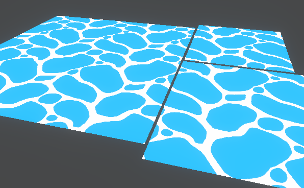
This post includes an introduction to using the Position node to sample textures rather than using mesh UV channels, which is also the basis of Triplanar mapping. It won’t be super in-depth but wil…
cool thanks
@thick fulcrum
@fossil cedar thx ya i ended up using the main preview
I think unity should change this though
the preview is basically stuck on "automatic mode", selecting the preview type automatically
but the user should be able to configure the preview node so it can be set to "3D mode" and "plane mode" as well
@thick fulcrum thats the tutorial
@crisp trellis agreed, it's another thing to add the list of usability / quality of life improvements for Shader Graph
Do you think If I changed the urp package so that it does what I want there is a way to suggest that to unity?
Not sure how easy it is, but I think all the code should be in the URP package
@crisp trellis i'd start with an unmodified shadergraph package, describe the limitation in a bug report and flag it as a UI/UX issue so they can clearly identify the existing behavior. It's pretty clear to say each node preview should have the same right click context menu that the main preview has
nice
i am doing same thing but my shader graph is not creating white ocean wave foam
@crisp trellis then if you want to modify / override the existing shader graph classes in the meantime, go ahead, just be warned, it's not pretty and due for further refactoring so it can be pretty challenging to maintain forwards compatibility
thanks i'll think about that
Can anyone help me outplz
@fossil cedar @crisp trellis Being able to choose the previews is something I've already suggested. It's been added to the roadmap here as 'under consideration', you can add some votes to show your interested in it if you want. https://portal.productboard.com/8ufdwj59ehtmsvxenjumxo82/c/76-preview-mode-control
Preview mode control would give you the option to switch between a 2D image and a sphere per each node.
@grand jolt are you working in URP or HDRP?
also if you didn't set defaults on the variables for tile and wave scale, make sure you adjust them in your material in the scene.
@crisp trellis You can make a PR to https://github.com/Unity-Technologies/Graphics/tree/master/com.unity.shadergraph, there is the ShaderGraph Code, and they have 7.x, 8.x and 9.x branches, if you make a PR it has to work on it's three versions
@grand jolt then you may need to change your position node from world to absolute world. Other than that, it looks correct from what I can tell... have you tried tweaking wave tile and wave scale on the model materiel in scene as he did in video?
Hello, I'm using a Shader graph and a particle system for this waterfall. But it is going into the wrong direction, i tried to fix the mesh in blender didnt worked. Can i rotate somehow the shader in the other direction?
(Blue arrow the actual direction, Red arrow how i want it)
set time to vector 2, and increase the the Y value
I mean, Time and Vector 2 multiplied*
Something like this. I have X on negative 5 because I want it to go to the right
Ah okay, thanks!
@thick fulcrum what can I find world and o change the wave scale and wave tile nothing happened but in preview circle its changing but not in scene
@wind obsidian the waterfall looks good
Thank you!
@wind obsidian how did u made that
@grand jolt I don't want to assume to much, but in the scene you have something like this screenshot. Have you tried changing the properties in the material section there and NOT in the shader graph?
Hello and welcome to, like, the 10 millionth water tutorial I’ve done. In this week’s video we’re looking at some more in-depth Unity Shader Graph features to make water, or an ocean, with shoreline/edge foam, depth, and waves.
Shader is compatible with HDRP., Edit: it used...