#archived-shaders
1 messages · Page 148 of 1
and it extra doesnt work if you use one of the spritesheets that arent bugging out like that, because it'll just interpolate between the desired color and black.
ok
let's put aside the weird preview thing 😄
I think this is just packing showing up, and you haven't answered on what component you used the material on in the editor, so I can't help you
BUT, I can tell you about the blending
here's the issue, afaik
ok there you go, so the sprite renderer doesn't have unit uv coordinates, it has the ones that match the atlas
if you apply the material to a quad mesh, or the default plane, it'll show the preview you have
indeed. and thats an issue if I offset it enough for the next image in the atlas to show up "close" enough to render in the slice. but im not doing that. let me try that tho.
anyway, it shouldn't matter, as long as your offset doesn't make your sprites bleed onto each other
yup. and im not offsetting enough to let one show in the other.
from the MainTex to the sampletexture2d?
you need to lerp your rgb channels, based on the mask you made (the substract + clamp)
and then you need to add together the original alpha and the new one, and saturate them
oh. yeah I can think of ways of solving this for this specific spritesheet. but the issue is that whatever I do to "ignore" the bleeding in the background, will look weird on spritesheets that dont bleed in the background.
It shouldn't matter what sprite you use if you lerp between the two colours based on the subtracted alpha
some of them have preumtiplied alpha, some don't, but this is alpha blended
Good point Cyan. Problem is that the alpha in the bleeding background isnt 0. Its 255 too. So if I do blend between the interpolation of thhem it`ll just give me a color in the middle.
Huh?
Whether the alpha is 0 or 1 (255), it wouldn't give you a blend between the two colours, it would output one colour.
Where T=0, it outputs A, and T=1 it outputs B.
the bilinear would, but you should use PointSampling Shapis
ah. right.
do you?
yes, ok so no interpolation problem 🙂
alright, so, lemme rephrase your objective 😄
you have an alpha sprite ( or sequence of sprites that are packed, irrelevant)
and you want to have an offset version of that sprite with a flat color "underneath", correct?
yes, above underneath. anywhere.
it matters
so Im doubling the initial sprite, offsetting one of them. subtracting the alpha of the offset by teh original one. clamping it so the 0 alpha but non 0 rgbs go away.
the original, un-offsetted sprite is 'on top' of the flat color, as in layers, not position wise
correct?
I dont understand that line. What flat color?
I'm having them both going through different channels and only adding together when Im inputing the color on master.
the photoshop analogy : you duplicate the sprite, the one under is offsetted and has a color overlay style
other than the alpha subtraction, they dont interact til being added at the end.
the objective man
oh derp. do you know what could work. just cutting off the sampletexture from its alpha.
and doing everything from there.
This is what you are trying to achieve, right?
yup. and it does work, on every single spritesheet except this one.
thx Cyan, I'm off 😄
If you preview the alpha output from the sample texture node what does it look like?
it looks proper, it doesnt bleed into the edges.
it looks just like the sprite, but without any color. and yeah. thats a good idea. just cutting that off of the weird bleeding sprite.
In my sprite I have it bleeding/stretching to the edges and the result is still fine
this right here is exactly why you need to deal with alpha separately
huh. indeed.
It's likely just the offset isn't perfect
mhmm.
btw thanks for the help guys, it has helped lots. im gonna try both ways, the way cyan did it and check if just cutting off the alpha works in an intuitive way too
Yeah, the sprite is an awkward height of 46 pixels, so the proper pixel offset would be -1/46. I just did 0.05 to test it.
ooor it could be just dealt with properly
How do you mean?
lerp rgb, add and saturate the alpha
I think that would just produce the same result. The gap is due to the incorrect uv offset.
It's already lerping between the original sprite alpha and 1 from the colour.
it wouldn't
you're doing the lerp from the original alpha to the solid 1.0 alpha of the color
based on the difference
if you add them, it has no chance of being anything alse than 1 on the transition
Right, but with point filtering there is no transition.
and it would also work with other sampling, because you rely on it being always point
Guess it just depends on what you need the shader to do / support.
If you wanted an outline around a semi-transparent shader for example you wouldn't be able to add + saturate the alpha values or it would remove that transparency.
this seems to work.
so would your difference
just doing this specifically.
huh. that works in the shadergraph preview, it works in the camrea, but not in the scene in the editor. huh.
i wonder if it has to do with opacity in the renderer.
like wth does this even mean in the scene. but not in the camera.
Hmm, you likely don't need the Color Mask, just One Minus the alpha result. You might want to Saturate (aka clamp01) to remove negative values after the Subtract).
Probably could also instead Multiply the RGBA and A outputs.
lemme try it that way.
good call. it works that way and its simpler.
Thanks lots btw guys. Sorry im retarded sometimes. ❤️
hey @regal stag and @wraith haven , thanks for the help earlier. Finally got it done. basically did what u guys told me to, oh and had to adjust cause it being applied to sprite atlases it was being distorted a bit.
I have been stuck for a long time now, trying to find out in my vertex/fragment shader if the current pixel is in the radius of any point light in the scene. Is that just not possible? I want to change the color based on if a light shines on it or not (no matter the intensity, just based on the range of the lights).
I have already tried using unity_4LightAtten0[i] and _LightPositionRange, together with the world position of the pixel, but they both seem to not give me correct results. Sometimes it does look like I get correct results, but then only in the scene view and not in the game view...
Any tips?
@rose remnant https://forum.unity.com/threads/get-the-range-of-a-point-light-in-forward-add-mode.213430/#post-1433291

Unity Forum
In order to calculate the light attenuation from a point light to mimic the same effect of Unity's built in shader, I need the range of a point light....
@mystic geyser I have seen that link, but I'm having difficulty finding out what's the important part in that shader that I should copy. And it seems like they just duplicated the pass and made it ForwardAdd rather than ForwardBase? But there are still some changes, so overall it stays unclear to me what exactly I should do in my shader...
Right now I have one pass in my shader, neither ForwardBase or ForwardAdd, and this is how I calculate if the pixel should be visible or not:
float distanceToLight = length(_LightPositionRange.xyz - i.worldPosition.xyz);
float attenuation = 1 - (distanceToLight * _LightPositionRange.w);
attenuation = (attenuation > 0) ? 1.f : 0.f;
```I use the attenuation to multiply the pixel color with. And that works as long as there's only one point light on the screen. But of course it doesn't work with multiple lights.
I guess that a pass happens for every point light on the screen? I just don't know how to add the results of those different passes together, if possible? Maybe your link describes how to do it but I don't really understand.Are the objects static, and the light positions static?
Is it a binary - is in range true/false?
I just want to check if the pixel is in range of a light or not, yes. The lights can move around though.
instead of checking if the pixel is in range, it would be nice to just check if the pixel is in a shadow or not. But i don't know if that would be easier/more difficult to achieve, or even possible at all?
Sure, you could have a separate custom shadow pass. There's a shadowmap created that you sample IIRC.
That said, what happens if it's in shadow? what happens to the pixel color?
The shadow map is just going to be of the main directional light, it won't take additional lights into account
Unless you enable shadows on all lights and sample all of them
and compare
Here's a tutorial on how shadow mapping works with multiple lights including point lights, IIRC (didn't read the whole thing).
https://catlikecoding.com/unity/tutorials/rendering/part-7/
A Unity Rendering tutorial about supporting shadows. Part 7 of 20.
The lights have shadows enabled.
When the pixel is in the shadow, I would just want it to be a certain color (or have an alpha of zero, doesn't really matter). But when the light hits the pixel, I want to just show my shader (as if it was an unlit shader not influenced by the amount of light on it)
So "magic lights" illuminating the scene.
Is that you @grand jolt ? (inside joke, sorry).
OK, there's a few ways. But do I understand that the lights and shadows don't influence the color? What about shadows "darkening" it?
That's correct. The lights and shadows shouldn't influence the color. Just shadow -> one color. No shadow -> something else.
So a sphere in the range of only one light would look like a hemi-sphere? (and maybe hollow one at that)
If I understand correctly, yes. As you might have guessed, my team is working with stylized toon-y graphics.
So not going for anything realistic here.
Basically, we want to have an even colour everywhere in the scene except for where there's light shining on stuff
By "even color" could it be like a middle grey everywhere, for example? (or whatever single color)
But the "lit" side of things would show up?
It's going to look really strange. IDK that's what you want. No ambient?
I mean, the even color kinda becomes the ambient color, right? But yes, we are going for that strange look.
Do you have a mock-up/sample? like a sphere or character? Before I lead you any further into left field?
Worst possible case I can think of is for you to pass in a list of light locations and ranges, and run through them per pixel. Not saying you SHOULD do that. But then you could set the original color however you want it.
How many lights?
We already have the base toon shader, which does what we want it to do. I'm now working on the water shader, which is a vertex shader while the previous toon shader was a surface shader. That's why I can't copy the workflow to this shader.
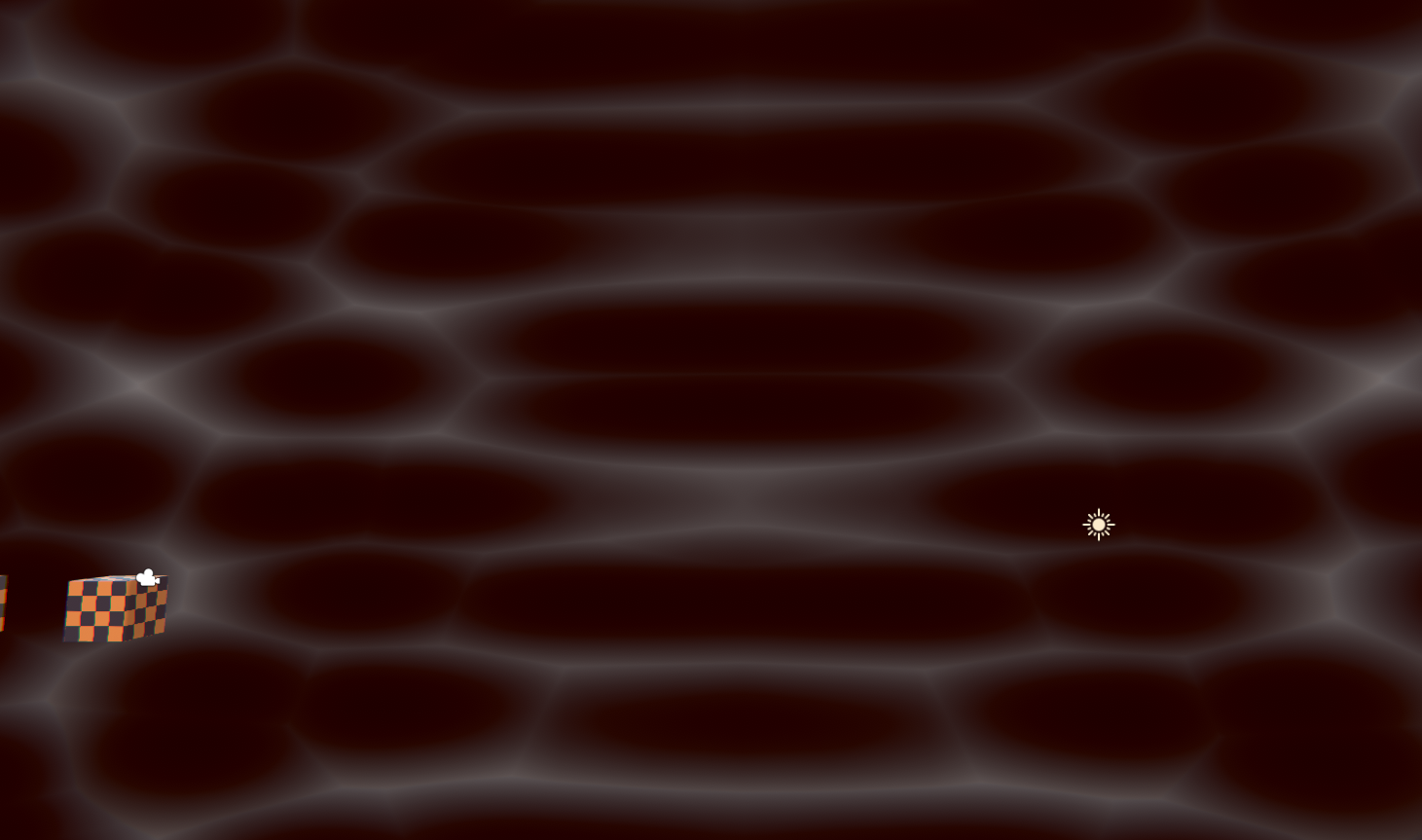
Here's a quick example of how we want things to look:
in the upper left of the screenshot, there's still geometry but it all becomes the same color because it is in the dark.
I'd rather not pass in all the light info by hand, but I'll look into it if there's no other possibility
(With "by hand" I mean via code of course)
OK! But for the stuff in the light it's shaded kind of "normal"! except for where the shadow falls on the floor...I think.
Can I ask what you did in the surface shader? Did you inspect that generated code to see what it did?
Because Surface shaders become vert/frags after generation.
There's passes for lighting and for shadows.
The surface shader has a Lighting function that takes lightDirection, viewDirection and shadowAttenuation as parameters, but I don't know where they come from
I did not look at the generated code, how would I do that?
If you select the shader you should see an option in the inspector to "view generated code". Warning: There's a lot of variants generated, so don't be intimidated.
Sounds like custom lighting. There's sections in unity docs about that too.
https://docs.unity3d.com/Manual/SL-SurfaceShaderLighting.html
Again, don't get discouraged, patience wins the day.
So maybe take a look at it all first so you know what it's all doing, THEN you can figure out how to make it work in your custom vert/frag/water.
do you mean "view compiled code"?
Mine says "show generated code".
There's also a "compile and show code" but that's different.
I don't see "show generated code". But I also notice now that it doesn't even see the shader as a surface shader to begin with 🤔
oh wait never mind, I was looking at the wrong shader. Sorry about that
I should go to bed soon haha
lol
I will take a look at that, and the links you shared, tomorrow. Thanks for trying to help me out!
It's a start. It will give you an overview of lighting and shadows. Also see unity doc and the catlike coding site, among any others you find.
You'll want to look at what passes do what. And also your existing methodology. You should be able to customize things from there. For water...might be interesting. 😉
I feel like the Unity documentation regarding shaders contains some of the worst pieces of documentation written ever, but yes I'll try to figure stuff out starting from the generated code and the catlike site 🙂
lol
something is wrong with the standard SSAO shaders in this unity version (2017.4.28f1)
I click run and it spits out about SSAO shaders "can't find include file frag_ao.cginc"
scratch that, i reimported all of it, now it's giving me an error related to VignetteAndChromaticAberration.cs
these are built in shaders
@magic thorn Sounds like you're using the legacy image effects, I'm fairly sure these no longer work in 2017.1+
My users and myself have several issues with shadergraph where it loses or 'forgets' the reference to the file in a custom function node
this happens frequently when upgrading SRP versions or doing reimports, or when moving around the .hlsl file
I get the console error 'failed to open source file'
but reimporting the graph always fixes it
are there some known bugs with custom function nodes and references to their .hlsl files?
hello, what's the best way of going about calculating min/max values of pixels in a texture inside a compute shader? Is it possible to do it in a single call? The only way i can think of is to take the resolution of the texture, lets say 1024x1024 and call a function of size 512x512 which would take 4 pixels and calculate min/max from them, then from 512x512 to 256x256, to 128x128, to 64x64... with the same process until we just have 1 pixel.
Did non exposed properties of Shader Graph always not appear with MaterialEditor.GetMaterialProperties or is it something new to 2019.3?
I missed this earlier: https://portal.productboard.com/8ufdwj59ehtmsvxenjumxo82/c/59-custom-interpolators
You will be able to perform custom calculations in the vertex stage & pass the results to the fragment stage.
also curious when this will land :p https://portal.productboard.com/8ufdwj59ehtmsvxenjumxo82/c/52-master-stack-and-stage-blocks

We're going to replace fixed-function master nodes with a flexible stack of shader features. You'll be able to build graphs that work on URP & HDRP simultaneously, and we're going to make it easier to understand your shader's performance through clear stage separation.
"when it's ready"
(yeah I know)
was about to do some SG modifications but then realized it's all changed under the hood on current master and chances are it's going to keep changing until this thing is fully done :p
@naive mural It's possible, but you'll need to use shared memory and atomics, and that might slow it down a bit. That should also tell you what to research. 😉
note the data type restrictions
Hi
Is it possible to put c code shader and compile it to a hlsl shader
creating a shader through c script
Moreover I want to convert the ultimate principled shader from blender to unity and add my own subshaders
Is there any tool to use like a cross compiler
hlsl and similarly cg are based on c language
so gotta be a way to do that
No
@meager pelican thanks
can anyone help me problem about adapting a shader to a plugin
just ask the questions
not many people will say 'yes' to 'can you help me' when they don't know what it is about
we're all here to help 🙂
well i converted a shader to use this alpha masking thing
and now its like twice as bright
idk anything about shaders really haha
you got any code/nodes?
this is the instruction i followed
i put breakpoints on the lines i added
and those properties etc above
gotta be honest at first I had
TOJ_APPLY_MASK(v2f, tex2.a)
Hi I've got this weird shading glitch on all of my environment assets, they work fine in Blender but once they in Unity they all have this black/white part that makes it look awful
I think it's because my quads on these parts look like this
but I'm not certain
nvm it definitely was that, instead of letting Unity triangulate my models I'm now gonna triangulate them in Blender because Blender's algorithm seems to be just generally better for some reason and doesn't create those weird problems
Hello! I'm trying to apply an offset to make a texture moves, but when I pass certain value, the texture gets distorted in a way that I don't understand, any help? thanks!
@river dawn The texture might not be set to repeat.
It's probably set to clamped
It's a field in the texture asset
Ok thanks!!
having a issue with distortion shaders with LWRP and shader grapic it seems to have corners like this https://gyazo.com/486242d8096dd58971b75cb66731326b and offset issues like this https://gyazo.com/d005d926c97a9572ff0cb7b947fe95a1
everything else works fine except for that
@warped field I'm not sure if this is an issue or not.
Distortion beeing an effect that uses the screen texture, I'm not surprised to :
- See the pixels wrap on the border when you offset the uvs
- See the "mesh" twice on the water because of the offset.
@warped field Make sure it's set to wrap if that's what you want. Also look into seamless textures for both the source and the distortion textures.
I have a Quad hosting a Mat with a PBR Master (PBRM) Node with a Sample Text 2D RGBA(4) -> Albedo (PBRM) hooked up, and that has a Texture 2D Asset Out (T2) -> Texture (T2) hookup. My Texture 2D Asset is a Render Texture which I'm writing to using MJPEG stream (all dandy and working) -- it acts as a big giant light inside any scene unless i'm super zoomed into the quad.. woah, thats a lot of text
how can I get it to not emit
on, in HDRP
Hello people! I want to mask off wind in our cloth shader using AO. I really dont want to have to manually paint all the models vert alphas since there are over 300...
no idea how 😅
Hey
How can I create a Blur UI shader in HDRP?
I didn't find anything so please help 🙂
@steel hawk I think you can make a pretty convincing blur with only the HD Scene Color node. It has multiple lod/mip map levels, each higher one being a smaller texture size, so more blurred when sampled.
You'd probably want to use the Unlit master. I don't use HDRP much but have had UI shaders work in URP using Unlit Master + transparent surface mode, as there isn't a real way to do UI shadergraphs yet.
Ok thank you very much
I'll try it and tell you if it works
I tried this but it doesn't work
I've also set the mode to transparent
@regal stag
Sorry I'm new to shader graph
It's probably not you. UI shaders aren't really properly supported in shadergraph yet.
This links to a discussion we had before, but they had it blurring on the full screen rather than the UI Image it was applied to.
Are you sure you've saved + applied the material to something?
Olento had it working in HDRP, but it may have been on a quad rather than UI, not sure.
Hi guys! Does anyone know how to set a Keyword using a material property block?
I have a replacement shader to display different shades on screen
but I wish to use it by each material, so I am using the following code:
#pragma multi_compile_local SHADE_RED SHADE_GREEN SHADE_BLUE
then later I am using inside frag #ifdef SHADE_RED ....
@thorny bronze Could be wrong but I don't think it's possible to set keywords with material property blocks, only properties. Could you not have a colour property instead?
Hi @regal stag , unfortunately not =/, maybe is there another approach using the new URP?
on URP there is a RenderFeature/Render Objects(Experimental) 🤔
I think replacement shaders don't work in URP, but it's possible to override materials per layer using that render feature. I'm not too sure what you are doing though or whether it would do what you want. Also don't think Material Property Blocks play well with the SRP Batcher, although that's optional.
you're right replacement shaders don't work in URP, you have to use a different function that I don't remember now
Probably the overrideMaterial option in the render feature stuff.
yes! 😄
tnks, I will look on URP
but, why did you said that " SRP Batcher, although that's optional"?
I'd say @regal stag is correct. Use a property. And conditional logic to set the color to Red, Green or Blue.
Since it comes in as a uniform value, it shouldn't impact the performance much.
Or just pass the color as a Red, green, or blue.
Yeah, depends if there's more differences than just a colour
Sure, but if it's based on a uniform, maybe a custom code block? Or whatever.
@thorny bronze I don't know a whole lot about the SRP Batcher. It's something that can batch multiple materials in URP using the same shader even if they use different property values. It doesn't play well when using material property blocks though from what I've heard others mention. I think it's designed as a sort of replacement to the GPU Instancing shader stuff?
This probably explains it way better than I can https://blogs.unity3d.com/2019/02/28/srp-batcher-speed-up-your-rendering/

Unity Technologies Blog
In 2018, we’ve introduced a highly customizable rendering technology we call Scriptable Render Pipeline (SRP). A part of this is a new low-level engine ren...
Hmm ok thank you 😄
Am I right in thinking that when using replacement shaders the properties (like colours/textures) are carried over to the replacement?
Right, because the URP overrideMaterial works differently. It replaces the material entirely.
But if you use a material property block, it will behave in that way. The properties in the block overwrite the properties in both the original and override material
@meager pelican I am learning shaders, I know that would be much easier implement using properties, but I am studing other ways to implement different stuff 😄
Yeah was about to ask if that would happen. Probably not a great option when using the SRP Batcher though.
Yeah, it breaks the batching
I started to study Unity Shader the last month, and there is some many "tricks" and hide features , and I dont find a good documentation which explain everything I could do. Like C# Microsoft documentation, so I am trying stuff to see what works and what doesn't
Thank you guys 😄
Probably even worse with the newer SRPs (URP/HDRP). Don't think there's that much documentation for any of it, except some small pages on each shadergraph node.
Shader features are more about chaning gross functionality (often via a toggle or some set of Enums) of the shader.
Like a shader that just colors using a texture, or optionally blends two or three textures. So you could have shader feature for One, Two or Three textures, and then have appropriate code for each option, adding additional tex2D lookups. That way, you have one shader that acts 3 different ways, and doesn't have to do 2 extra "fake" reads of a "null" texture when it doesn't have to. Just for example.
Similar to c# conditional compilation.
Yea, it produces multiple variants of the shader. Also worth noting shader_feature's get stripped from the build if unused, while multi_compile doesn't. https://docs.unity3d.com/Manual/SL-MultipleProgramVariants.html
hey, i'm new to unity and i'm having trouble getting a quad to cast shadows when using directional lighting
Hey guys, I had a question. Can you use actual .shader files in HDRP or URP?
or are they both strictly shadergraph
You can, if you're brave enough
You can write hlsl code shaders for URP (and I assume HDRP too). It's a bit different from the built-in pipeline, and some things like surface shaders aren't supported.
Can look at one of the shaders URP provides as an example. https://github.com/Unity-Technologies/Graphics/tree/master/com.unity.render-pipelines.universal/Shaders

GitHub
Unity Graphics - Including Scriptable Render Pipeline - Unity-Technologies/Graphics
As long as you don't need lighting, it's not so bad. Only difference is a couple of macros if you want it to be batched by the SRP Batcher
I see. When you say "some things like surface shaders aren't supported" does that mean there's no built-in library for it, or that it's somehow incompatible with the renderer?
There's nothing like surface shaders in SRPs
You have to write vert/frag shaders
Surface shaders generate shader code for the built-in pipeline
Which won't be compatible with SRPs
I see.
But thinking about it, @amber saffron couldn't you get something kinda similar to a surface shader with a custom function node, for those that want to write their own shader but want lighting to be handled? The custom function would just return the PBR properties, Albedo, Normal, etc...
Which then connect to the master output
Yes, totally.
I'm concerned about setting the game up early to be able to look good long-term, and unfortunately have never really touched rendering pipelines in unity before. I was interested in HDRP, but we have a handful of shaders that I've made over the last couple of months that it would suck to re-do.
Hello! My shadergraph is not showing previews in the multiply nodes, what can I do? thanks!
hey, we need more information to help with that. what do you mean by "not showing previews"? what does your graph look like?
hey, we need more information to help with that. what do you mean by "not showing previews"? what does your graph look like?
@stone sandal for example this
@river dawn Does it change if you set the alpha of the color to 1 instead of 0?
same
Probably not, the previews don't show alpha
hmm that looks like a bug though, it should still have the 3d sphere in it
what version of the package and unity editor are you using? some of our releases for 2019.2 had a lot of bugs with the preview window
if you're able to
the 7.x packages for 2019.3 have a lot of good bug fixes for shader graph rendering
Ok, I'll try, thanks @stone sandal
I got it solved I had to reduce the addition to the distort it fixed it
uv map the fuse first @grand jolt
A height dissolve shader would probably work. It might only need a One Minus to go the other way.
yeah i guess that should work. Just pan thee mask texture along the uv
@maiden stag When some nodes are connected, like the Position or Normal Vector, it turns all nodes after it into a 3D sphere preview rather than the 2D square. It's meant to be like that. The second image is likely in an older version where it was bugged. (Though I'm hoping something that allows us to choose which previews to display is added though, as I prefer the 2D ones)
oh but my effect isn't the same it looks way worse
Hard to tell what the effect is supposed to be.
I assume offsetting vertices based on normal direction + noise from those nodes, so it might only look good if the object/mesh is subdivided a bunch. Since that noise is sampled based on the UVs, it would need to be uv mapped too, but it would likely have seams, unless it's just being applied to a plane.
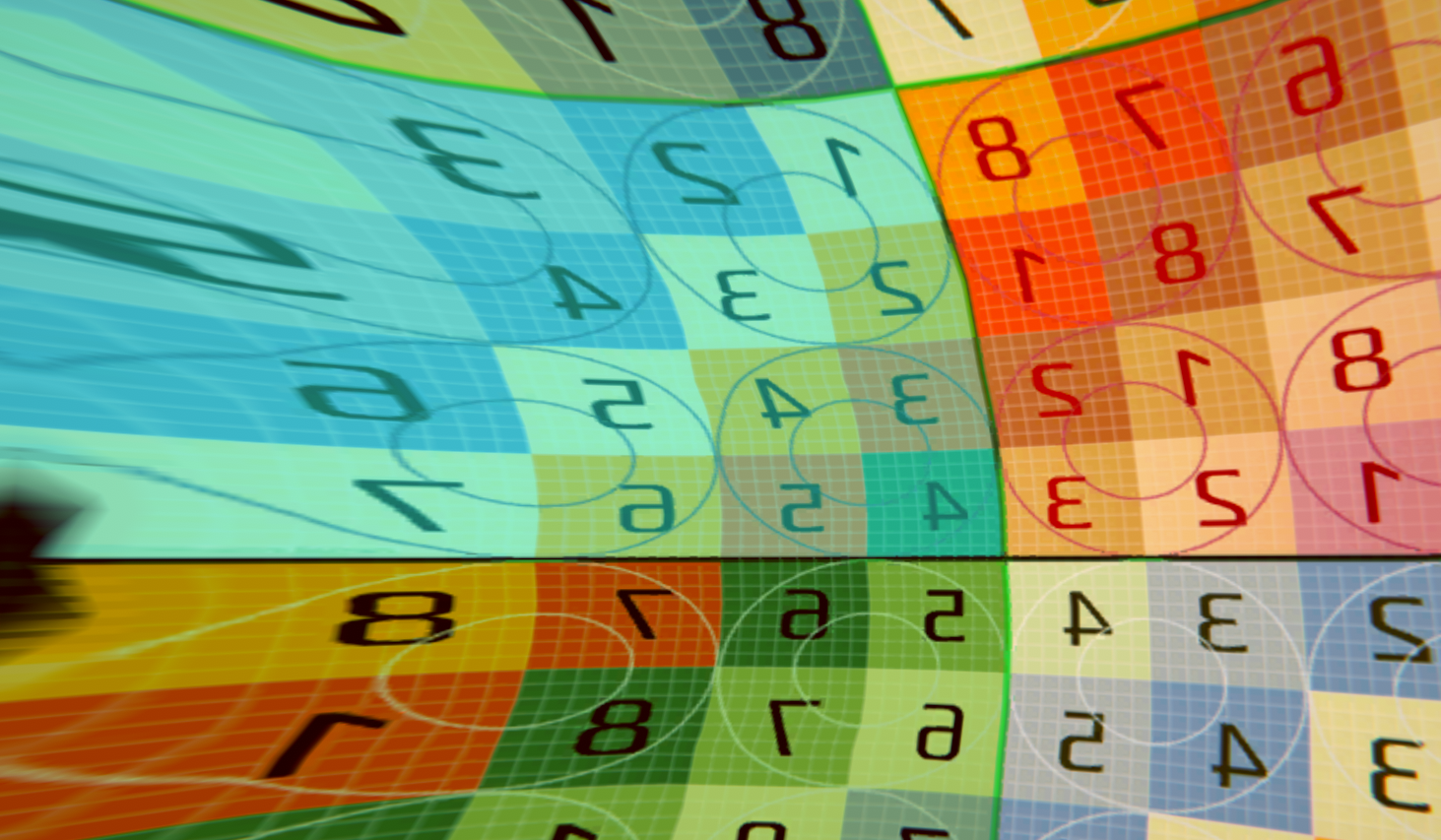
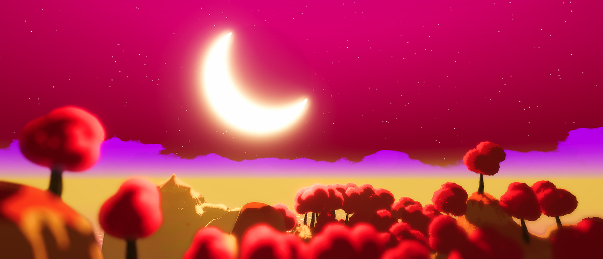
Working on a skybox shader, and trying to create stars using voronoi noise
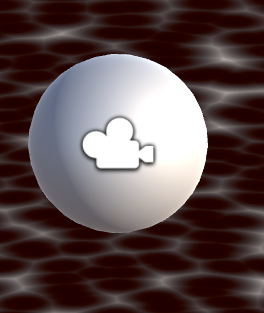
However running into an issue where the noise is stretching really hard on the skybox material along the seams
Anyone know what's going on exactly?
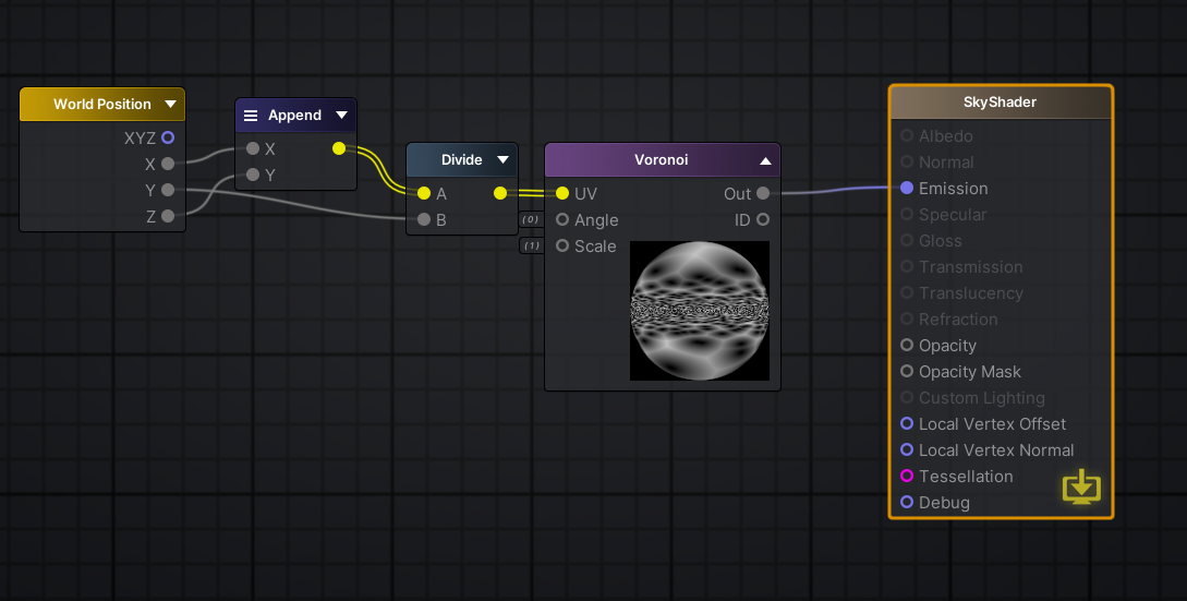
Im using voronoi with texture coords hooked into it
well, the skybox's uv are probably not what you expect
it might make more sense to be a 3d vector, to fetch a cubemap
The skybox UV seems to be equal to the Position node set to Object space. It's 3D rather than just 2D.
The Voronoi node uses a Vector2 input so it takes the XY components of the UV output. Since it ignores the Z component it appears as stretching along that axis.
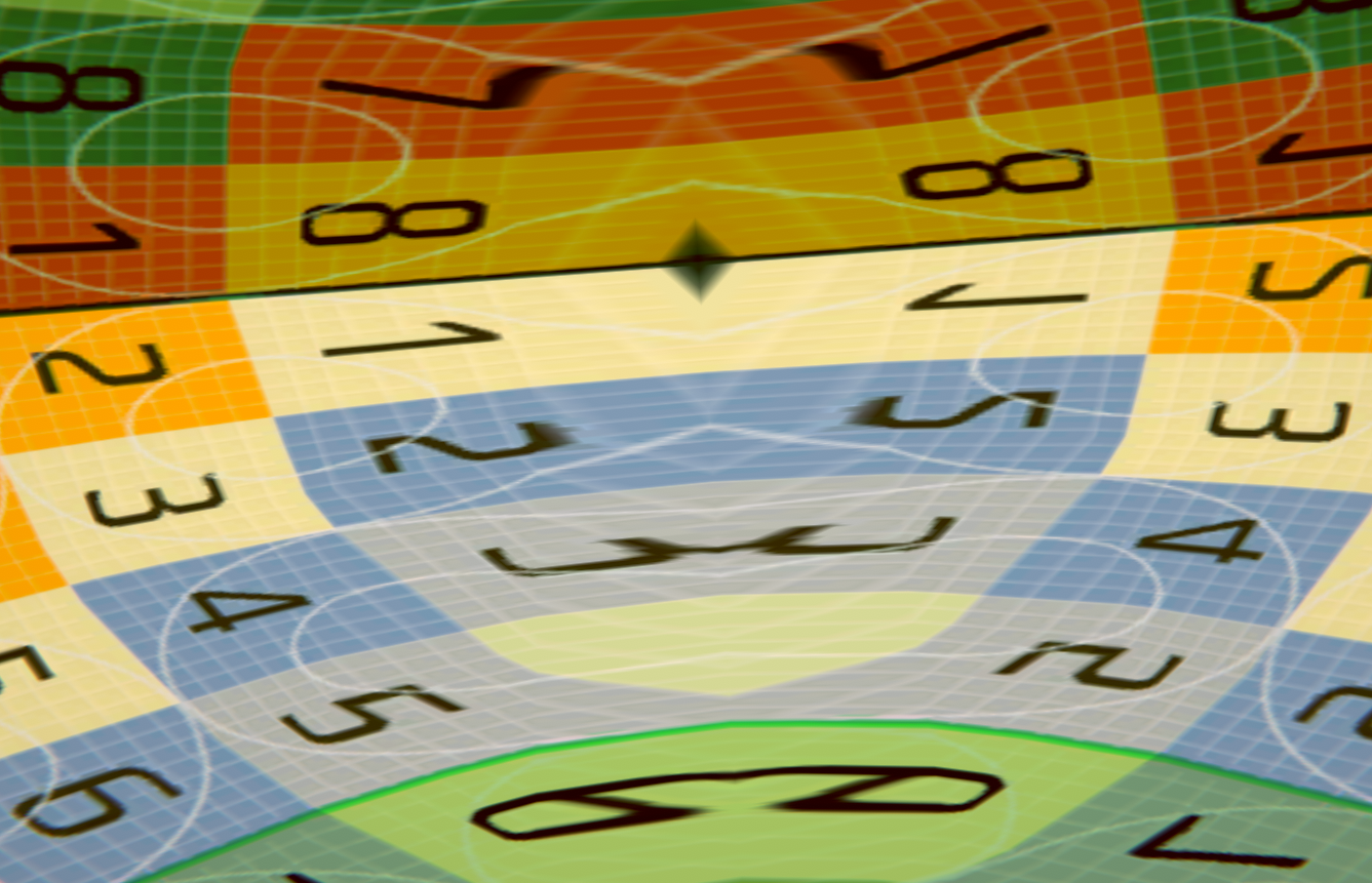
It's like if a sphere was composed of two domes
and you truncate it like Cyan said
the connection is where it stretches
You may be interested in this : https://medium.com/@jannik_boysen/procedural-skybox-shader-137f6b0cb77c
I was actually just looking at that xD
your problem is a bit more complex, because even if you had texture coordinates mapping to a cube, you would still have no tiling with the top face
It goes over how to fix the issue it seems
It's either that (remapping UVs / world position), or using Triplanar mapping (but that's more for textures, might be a bit expensive with generated noise).
atan is not a cheap op, but if you don't aim at mobile it's probably fine
Yeah it's for a skybox
for VR
Is this a common issue people run into when making procedural skydomes?
One thing of note. In that blog post they put the UV stuff into a subgraph and use it multiple times. It would be better to only do the calculation once and reuse that output instead.
you could just use a custom mesh with your own UVs
VR would probably benefit from having as little wasted resources as possible
and you could do stars with a texture really
Question since I am new, how would I use a custom mesh for a skydome?
parent it to your camera, make sure you draw after all your opaque geometry so you waste as little fillrate as you can
Like do you mean create my own sphere and unwrap it the way i want
yeah, or a cylinder and cap anything that fits the texture repetition you need
since there won't be any parallax
Huh didn't know you could do that
Is that a common method of doing skyboxes?
I mean, I've done a lot of work in Gmod - not sure if you've played - but what they do in there
you decide ^^ I used to do this on PS2, since there was no built-in system
is they have a dedicated area WAY off in the middle of nowhere filled with effects and assets
and they somehow project that to the sky
Does that sound familiar?
I'm not familiar
lol oof
ah I see what you mean
I think World of Warcraft also does this
this used to be the same in early unreal afair
but this is a 2 step process because a first camera is rendering a mesh to a texture, which is then rendered to the main screen, or maybe rendered beforhand and the main camera doesn't clear
So for what you said earlier
in your case you could get away with just rendering a mesh with the main cam
you should probably do this in script, since you don't want the mesh to also rotate with it
just fetch the camera position and assign it to your transform, but not its rotation
probably in lateupdate as well, to ensure there's no delay in that catchup, since the camera probably moves with the game logic in a regular Update
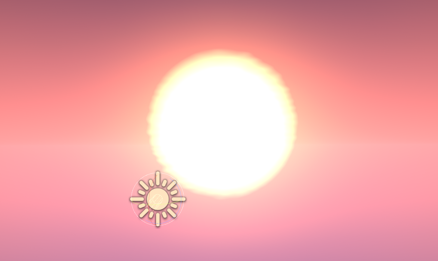
I was also looking at this tutorial right here: https://www.patreon.com/posts/making-stylized-27402644
then make sure that the radius of the sphere matches up with the near and far plane of the cam
and it doesn't mention having to do any of this which confused me
I couldn't even get the sun implementation working because my results were so drastically different
you could do anything you like in a shader tbh, but it comes at a cost
and I am pretty sure it has to do with the way the skybox unwraps
it's a tradeoff, maybe its fine for your usecase
but VR rasterize once for each eye, at high frame rate, for a lot of pixels
mhm
I feel like there's not a whole lot of stuff on animated skyboxes
maybe I am not looking in the right spots
but also, how prevalent is it in your game experience? is it a star gazing game? or do you see the sky in a glimpse between two buildings by the window?
Minions Art's skybox uses worldPos.xz / worldPos.y for the stars/voronoi texture. In shadergraph it would be :
yeah, which is what gives this "ceiling effect"
which could be a thing for stars if you like, and is also definitely a good way for layering clouds
gotcha
also the problem with computing the texture coordinates with math is that it prevents texture caching

so the fillrate is a lot worse, especially for large textures or poorly compressed
Yea speaking of the Minion's art tutorial
when you use vertex UVs the hardware knows which part of the texture will be sampled, and caches that area
I could not get the sun implementation working at all
Actually I will reconstruct the graph real quick just to test again
because I like the concept look of it
but yeah, ran into problems
yup, it should be pretty straighfoward as far as I can see
but you should look into not using distance
it's also an expensive function rto run for every pixel on screen
but again, pre-emptive optim and all 🙂 root of evil yadda yadda
maybe it's all fine, maybe you have a dedicated hardware or a known min spec
I don't know
What's an expensive function, voronoi?
distance()
distance is expensive? O.o
distance has a square root
I thought distance was simple vector math
everything is simple vector math 🙂
but what makes dist more expensive than any other thing?
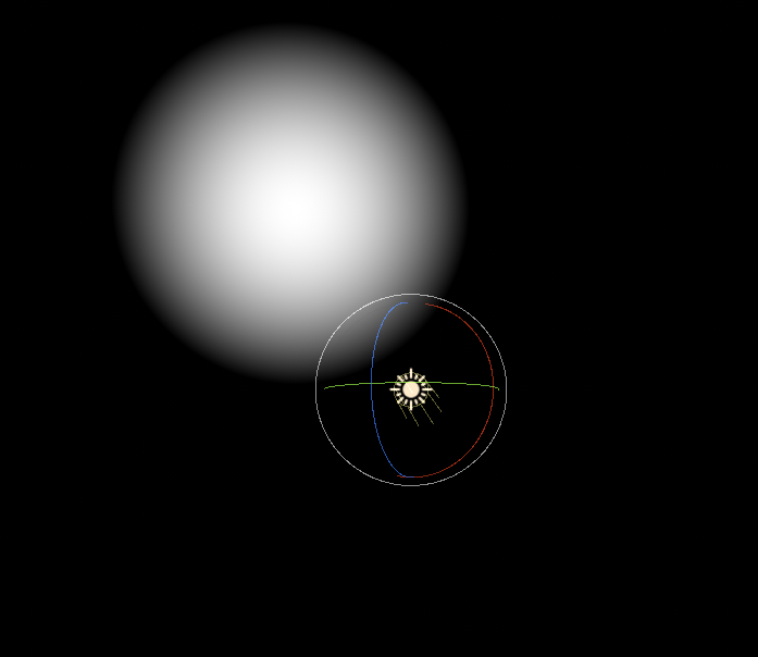
Also yeah here's my issue immediately

it's pythagoras, the sqrt of the power of both other sides
so by his tutorial, dist of uv coords and worldspace light pos should give him that result
i just get this blob
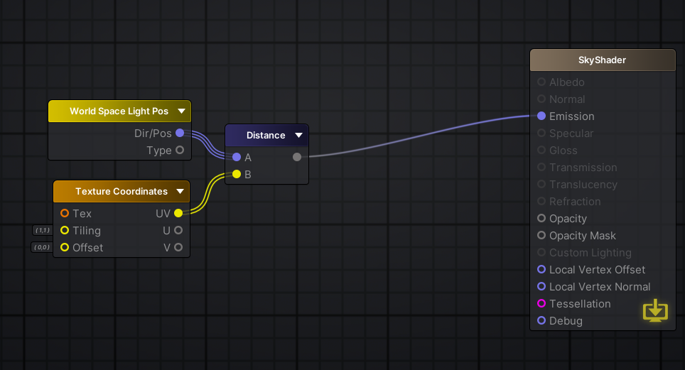
should be pretty straight forward
your UVs are vector 2
her*, and it might be due to Amplify's UV output being a vector2
so again one axus is dropped
Oh my bad
Oh i found the fix
didn't know you can just swap texcoords to a float3
I suck
lol
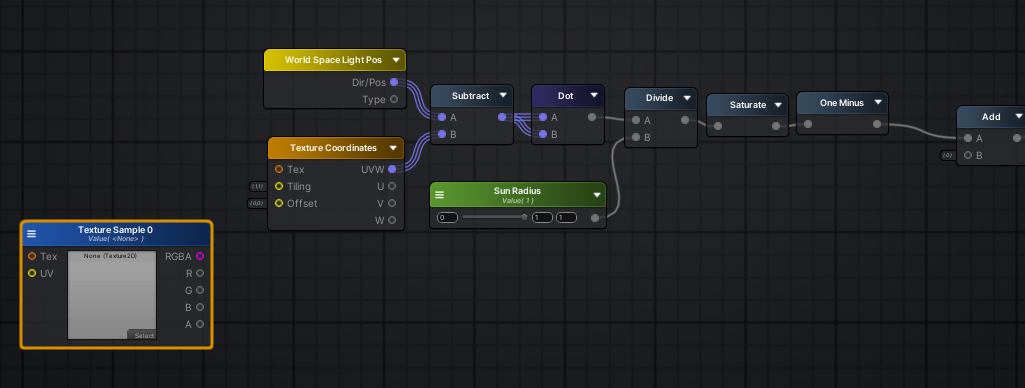
so you could do "vector = wp - UV" and then dot(vector, vector) to get the squared distance
and then use the squared radius
to get the same effect, but without the square root hidden inside distance()
especially if you intend to do the moon and it's shadow the same way, it adds up
yeah the vector dotted on himself is its squared length
it's the same but a bit bigger
That's more performance efficient?
substantially
really? o.o
if math is your bottle neck, or battery
(also crazy shit is happening on GPU, it's hard to keep up)
Do you learn this just from experience over time, or?
(maybe there's some lookup for that op on some hardwares but not others, etc)
the sqr distance thing is a bit of a textbook case
which is also why Vector3 has it
(but I definately learned over time because I was trained as a designer)
How long have you been doing this stuff?
Damn
post your results when you have something 🙂
Oh ok
it's working btw, I am just adjusting 😛
I think I might be able to use this potentially as a mask as well
if need be
I could also distort this with a noise texture right, to maybe create a slight wavy effect
definately
overall, fetching large-ish textures with procedural UVs (computed with math) is bad, and with dependent texture fetches (with the influence of another texture) is worse
but noise can be a small tiled texture, and be pretty efficient
I was going to use a perlin noise texture that's like 256x256
same goes if you sample a gradient in a lookup for example, caching doesn't matter because the whole texture probably fits in the cache
256 is pretty big
o
you can probably do 1/4, and maybe sample it twice at difference scales
how would I distort the sun with the perlin noise in this situation?
I'm biased, modern GPU are beasts, but what platform do you aim at?
PCVR, HTC Vive, Oculus, and Index
meh, I guess you're fine with fancy ^^
It's a long road ahead
I've only really been working with this stuff for less than a week
yeah, I would watch out for Quest and that sort of lower end headset
anyway, if you want to distort anything, just add to it
I did try that, because usually it works, but this is kind of a different case no?
you probably want to offset the texture range before adding
what effect are you looking for?

technically the sun shouldnt deform, except some heat wave
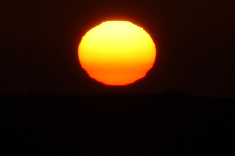
😉
at a high level that looks like a noise texture scrolling upwards
distorting the sun
yeah, sample your noise , then sun pos + (noise - 0.5f) * distortionintensity
to move the wave uward just add the time to the vertical axis of the coordinates of your noise
oh wait
i wonder if i'd just hook that into the texture coordinates node
not sure if i linked this or not
yeah same, you can add the noise to the sun pos or the other position, since you take the difference anyway
(i guess, it's late)
oh lord that's hella strong
one sec
Hmm this isn't working the way I thought it would
and probably use different intensity for horizontal noise btw
So I tried inputting the noise into the texture coords offset, didnt work
and tried adding the world space light pos with the noise texture
also doing weird stuff and not working
what does weird stuff looks like? it probably needs to have a very low intensity, since 1 would offset over almost 90deg
before adding the texture right way, substract 0.5, and multiply by say 0.01
tadaaa
the texture has a range from 0 to 1
and the vector of the direction is normalized, which means the maximum length of its components is also 1
so adding something that large makes the value swing by a lot
damn
this is only to get some nice visuals anyway
haha, well that's pretty low frequency, and perlin is an addition of linear values anyway, so you can duplicate the layer in PS, offset, and fade the edges, and it'll look EXACTLY like another perlin noise
I think Gyazo can, if you're lokoing for something that has hosting as well
but I use Screen2gif, has a bit more control
a lot more
I used to use gyazo
does gyazo auto upload to imgur
thats one reason why I like sharex
not imgur, I think it's their own stuff, hence their monetization I guess
you're welcome, gl with your project
anyone have a tutorial on how to create this look someone posted on reddit? https://www.reddit.com/r/Unity3D/comments/g4ompv/experimenting_with_some_realtime_hand_drawn/

reddit
1,190 votes and 65 comments so far on Reddit
looks great!
it's mine
you got any specific questions?
The materials are all unlit, I apply a toon shader with a 'lit' color and 'shaded' color
based on this
@devout quarry sorry am still a super noob with shaders. Let me have a play with the link you sent and ill let you know if I get stuck! Thanks
@wraith haven I have some other questions if you are still available to help / not busy
regarding the same thing actually
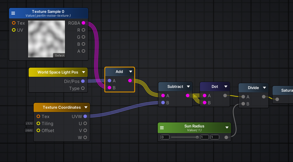
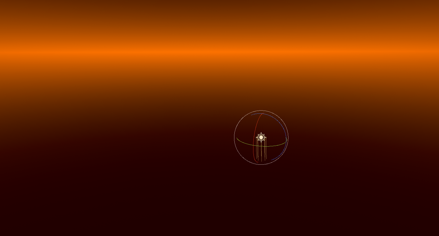
Im looking at Minion Art's horizon logic and I see to be getting different results
This section right here
looking good Calum 🙂
The Horizon should be when the sun is at, well the horizon of course
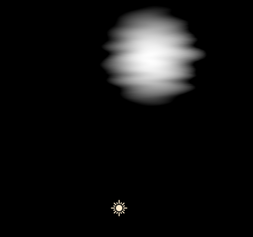
I implemented the logic in Amplify, yet the horizon only appears at sun's peak
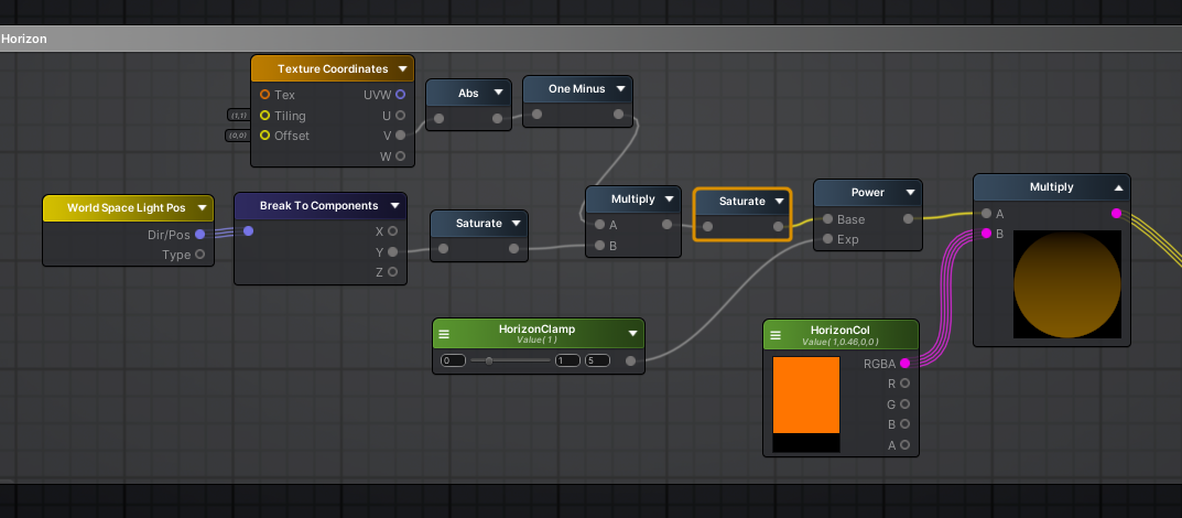
Here's my logic: https://i.imgur.com/hiFUbgj.png
what's sun peak?
could the info you have be wrong?
ah lemme look at the graph sorry
ok I get it now
I think the horizon should show up with the sun's Z value is either 180 or 0
or of course when they get close to those values
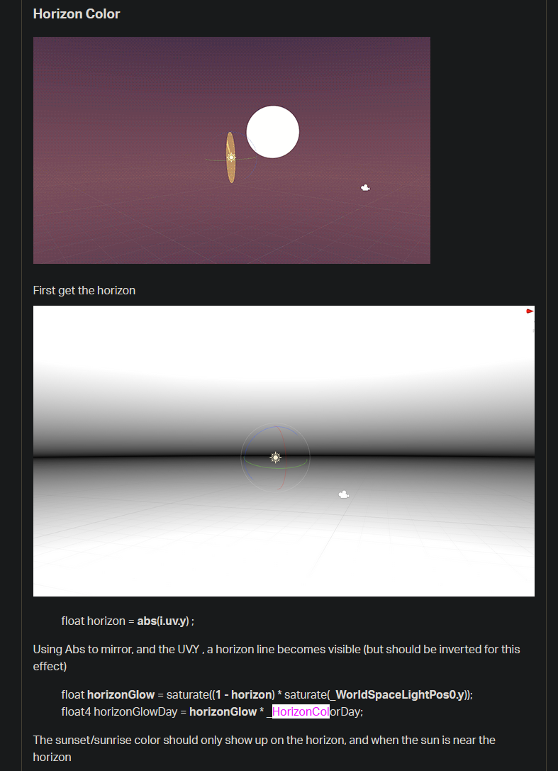
so, the logic here is the get a glow that is proportional to the time of the day, and the time is approximated by how high the sun is. the .y component of the sundit. is exactly that value, and saturated so that it doesn't have any influence when bellow the horizon
Might want to look at this line again saturate[ (1 - horizon) * saturate(_WorldSpaceLightPos0.y) ]; I've swapped out the brackets for square ones. You seem to be doing the saturate on 1-horizon then multiplying, but it's the other way around.
Made the same mistake before. So easy to overlook the brackets when you are reading stuff kinda backwards to recreate it in graph form.
I fixed it
surprisingly did nothing
Yea you kind of have to think backwards with nodes a bit
Hm, so it didn't fix the issue?
Yep did nothing
@devout quarry when i download your toon shader i just get this pink
Are you using URP @naive mantle
woops @grand jolt , think not
yeah I just created basic 3d project and not added any RP yet
can i retrospectively add URP / HDRP
and any advice on which one to chose?
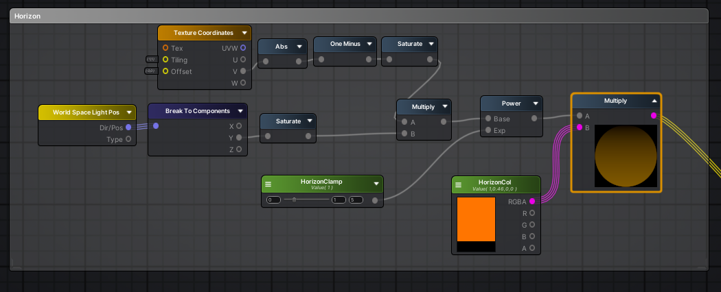
@regal stag Okay I sort of understand the logic here, 1- abs(uv.y) give you the horizon line no matter what
and they are multiplying that by the worldspace light pos to essentially let it be on and off whether or not the sun is pointing at the horizon
I use the built in pipleine @naive mantle
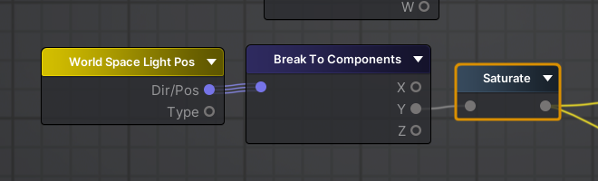
If I recall correctly, _WorldSpaceLightPos0, even though it says "Pos" it's actually a direction when using a directional light.
So the problem is that the worldspace light pos is only working in one direction
If you are using @devout quarry's shadergraphs I think you might want to use URP as that is what I assume they are written for.
Oh really? Good advice.. also good to know you cant "revert" adding HDRP according to the docs, so glad i took a backup first
Yeah I am a bit confused by how this is working
Should be able to uninstall HDRP, it's likely just much harder to revert as you have to manually change all the materials and stuff back. (If you haven't upgraded materials yet that's not a problem though). Unless it is actually impossible, but I kinda doubt that.
If you point the sun down, the background turns white
and visa versa turns the background black
I don't know how they would be using that to show just the horizon
Is the Power to adjust the size of the horizon?
Then I think you want to do the power before the multiply too
Power isnt even hooked in right now
I see, perhaps the tutorial is wrong

ah yeah... much better 😂
Looking at this gif
I think it might be a sunset/sunrise glow
think i just need to update materials
To make it orange when the sun is at the horizon
They are definitely not just multiplying a color when the horizon is visible
Or maybe they are
But i feel like that transition is way too sporadic
So I think to get the logic working
I need the background to be white when the sun points at the horizon, and black elsewhere
and when I multiply that by float horizon = abs(i.uv.y) ;
it should make the horizon only show up when it should be showing up
That'll just output the raw horizon
I need the horizon to show only when my sun/directional light is angled at the horizon
This right now is all I have plugged into my skybox
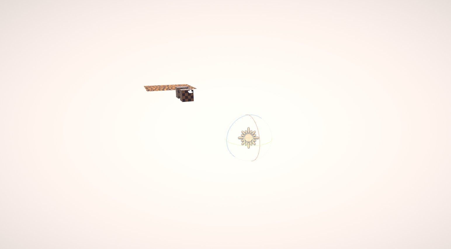
when I point my sun down it turns white
and when I point up
I think the tutorial might be wrong
Yeah, I meant float horizon = 1 - abs(i.uv.y), so it's white at the horizon line instead of black. But yeah it needs multiplying with some kind of direction
yea I got that ez
ohh
this might be the wrong node
So if I plug in JUST the world space light pos into my skybox
I get a bunch of colours based on the direction of the light
but no matter what
if i point it upwards, it fades to black

I think what you want is this
yes!
that looks correct
why does abs do that?
absolute always returns a positive value
but I thought black = 0
so Y is 1 when pointing up, 0 when pointing at the horizon and -1 when pointing down
By absoluting it then taking one minus, we get 1 at the horizon
thanks a million
Still confused as to why saturate was used in the tutorial post though 😅
That has to be a mistake
Okay multiplying the horizon actually does give a nice effect
Uhm this might be a dumb question
by say if I wanted the lighting colour to change during the night
would be a stupid idea to parent another directional light in the opposite direction to the sun?
like that
I mean it works but I just don't know if it's a stupid idea
guys sorry for the n00b questions but how do i fixed this pixelated shadows? It wasn't an issue before without URP and i tried uping the pixel limit to the max but thyere still really visible
This is actually why I switched from URP
it looks terrible 😂
Someone correct me if I am wrong, but the shadows are really bad
I did a comparison of two project, standard vs URP
standard was way better
standard also has better support and is more stable
standard being default or is standard another RP?
standard AKA built in rendering pipeline
I've also seen a lot of warning posts to not use URP for game dev
and someone even went on a rant about how bad URP is in general discussion
whats the argument for not using HDRP? performance?
hmm seems people are suggesting to try adding shadow cascades
well ill be damned..
that looks a millions time better.. but at what cost 😂
I guess back to standard it is 😛
For like a surface shader, I want to reduce the attenuation of the dark areas of objects in my scenes while still receiving shadows, I've created a toon shader in shader graph and that does kinda what I'm looking for but it also doesn't receive shadows at all... Is there a well known way to do this?
You would be able to author shaders that use Tessellation for HDRP. This will allow you to dynamically add detail to your meshes.
Vote Today! Tessellation HDRP for Pres!
what are matrix properties for in shader graph?
they cannot be exposed, they do not compile to the given names nor do I get control over the names
so when i compile i get names like Matrix4_47228E9D
and cannot control that afaik
and its a part of per mat cbuffer
so i cant treat it as a global
and i even get a warning that this exists even though its not declared as a property in the material
and the default values dont seem to be persisting to materials either so im just having trouble understanding who these properties are for and what I am supposed to do with them
@grand jolt you can set the names in the shadergraph 'blackboard'
I wrote a shader to displace vertices and it moves whenever my camera rotates/moves. Why is that and how do I fix it?
@grand jolt The reference can be set in the blackboard as Lecks mentioned above. Unlike other properties they aren't exposed, but you can then set it from C# using material.SetMatrix, see https://docs.unity3d.com/ScriptReference/Material.SetMatrix.html
(There's also Shader.SetGlobalMatrix if you want multiple shaders/materials to share the same matrix property. For most properties it is "global" when the property is not exposed, but as matrices can't be exposed, I would assume the material.SetMatrix one might override the global one if both were specified?)
Yeah, im glad to see they updated that but Im working in 2019.2 where those options are not present.
so i am stuck with using 4 vectors
unless my client chooses to update unity which i doubt he would want to do for somethin as insignificant as this
Ah, wasn't aware it used to be like that. If they can't update, I guess vectors might be the only option then (and construct the matrix in the graph, assuming you need it as a matrix).
yeah, was just really frustrated that that feature at least in that version has basically no use that i can imagine and the workaround of using 4 vectors hurts my soul
personally used to writing shaders myself but this client wanted a shader graph so just have to deal with the oddities
The only other method I can think of is using a custom function to specify the matrix... although in the older versions it worked differently and I can't remember if you can specify stuff outside of the function like you can in the newer Custom Function node (at least when using the file mode).
ohh i didnt know I was able to specify stuff outside of the custom function ill definitely give that a try next time, thank you!
I'd probably ask the client if updating shadergraph is possible though, as there's lots of bug fixes and newer features
@fluid lion Is this in shadergraph? What does your graph look like?
@grand jolt I'd like some source on this
Shadow cascades look awful in URP
they look way better in standard
In my own testing, shadows look nearly identical in URP and standard.
And if I try googling "unity urp shadows bad" or "unity urp shadows cascades", I can't find anything that claims that URP is worse than the built-in renderer.
https://issuetracker.unity3d.com/issues/rotating-an-object-with-world-space-triplanar-normal-produces-different-lighting-shadows-orientation I'm experiencing this bug, which is fixed in URP 7.2.0. However, according to my package manager 7.1.8 is the latest version of URP... Any way to get the newer version?
How to reproduce: 1. Open attached project "f4-bugs.zip" and scene "SampleScene" 2. Select Plane 3. In Scene view, zoom in on a pivo...
You need to press the little arrow next to the package name to reveal all the package versions
There you should see newer versions. If you don't, then there is no newer version for the Unity version you're using and you may have to update Unity.
Am updating now, hopefully it is stable enough. It doesn't have that verified tag yet... Thanks!
Sigh, it appears I have a different bug... I'm fighting these weird triplanar normals. Every time a light gets close to the surface of a texture that has a normal (even a perfectly flat RGB(128,128,255) one) it creates this weird 45 degree shadow on the surface.
Same image, no normal maps applied to shader
Node setup for normal maps
Is someone aware of a vr mirror shader working with HDRP ? The only one I found in asset store doesn't work for HDRP 🙂
does anyone know how to kind of make the urp lit shader but in shader graph? what settings do you have to use for the texture assets? specular map for example ?
ive gotten the other maps to look lik ethey work but the specular one isnt working right
right now im using default except for the normal i have it set to "type normal"
space is "tangent" for all of them
Can you show your node layout ?
ok btw i dont actualyl know anything about what that stuff means i was just trying stuff and comparing how it looked
thats the relevant part
let me know if any of the other maps are wrong too, occlusion doesnt really seem to change anything when i change the value although it didnt on the urp default lit either
Do you mind also showing your specular map ?
ok, its from the dark city 2 asset
(you should try blending occlusion with 1, not 0)
oh i see
occlusion still doesnt do anything, anyway that texture there is the specular map
_ao texture is an occlusion map right or is that something else ?
should be this
are you sure that it's supposed to use the specular and not metallic workflow ?
not sure but it looks fine in the regular urp lit when i choose specular and use that map above as the specular map
i can see the water becomes shiny but the bricks dont
but on my shader graph one the whole thing becomes shiny
also, for the normal map : to control the intensity, don't blend with 0, use the normal strength node instead
oh let me try that
when using the urp/lit shader, you should have the choice for the smoothness input, either "from albedo alpha" or "from specular alpha"
looks like your specular map has smoothness in alpha
so, take the A output of the specular sample, multiply with the smoothness slider, and plug in smoothness of master node
and keep the map still mapped to specular ?
@low lichen I did a direct comparison between the two with screenshots and everything. Even the guy who just asked because he had an issue also did it
He immediately saw his shadow issue fixed
I had the exact same settings
it looks different now, but im not sure, is it possible i need to invert something ?
like a one minus
or maybe i just need to change some values
the urp one has a sun reflected in it, i guess maybe the skybox or something or the directional light not sure but im not seeing that on this one
yea otherwise its looking the same now
nice
thanks i didn't know how this stuff worked. btw these assets haev an _ao file. i thought it was occlusion but it doesnt seem to do anything, even on the urp lit material. Am I wrong about that ?
Should totally be occlusion. Note that it's supposed to block ambient lighting (hence the name, Ambient Occlusion), so if you don't have ambient, it's not supposed to change anything
This can be as simple as baking the light in the scene to have the sky ambient probe
oh i see maybe thats it thanks
btw i did this just so i can have a crossfade dither animation on LOD group stuff, kind of annoying unity's built in shaders don't support it
do you know if essentially reimplementing the lit shader using shadergraph is worse performance than the actual lit shader ?
Should be similar
ok so i see now the skybox's sun reflection on my shadergraph one is really small in the reflection, but in the urp one its really big
do you know why ?
What is the graph looking now ? 🙂
i just did what you said
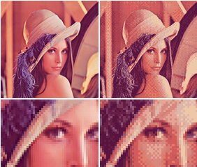
this is the comparison though
the first one is the shadergraph
second one is the urp
you can see the sun is bigger on the urp
its really small on the shadergraph one
kind of in the middle left/upper left
Still, can you please do a screenshot of the updated graph ?
Hum ... should be ok ...
yea i mean it looks ok its just the sun is smaller on it than in the urp one
Maybe, for some odd reason, use R output of the AO map, instead of rgba
ok although i still dont know how to test it
@fluid lion Is this in shadergraph? What does your graph look like?
@regal stag No this is by a shader script, not by the graph.
still looks the same to me although its probably because i dont have ambient light as you said
should i use rgba or R for AO after switching to lerp ?
Still use R
thats the ao
AO being a float value (light blue connection), the channel connected should be the one you use to store it. In single channel textures, it's either R or A
Please avoid sharing directly source assets from a paying package :/
ok so i can see the ao now
i can see it with either r or rgb
looks like lerp is what made it work
so you are saying r is better to use than rgba ?
using RGBA will work because at the end, only R channel will be used on the master node (when vector4 is cast to Vector1)
but using R since the begining will avoid to do calculation on 4 floats
ah i see right
As for the issue with the reflection ... I don't get it
is it better to manually take r g and b into a vector3 then into the destination rather than just doing the whole rgba into it ?
like for the specular map for example
Well, this is no easy to answer. You will have to do casts in order to do this anyway, so it will only add more code to the generated .shader code.
But in the end, the final shader compiler might optimize this very well anyway sooo ... in this case, no need to convert
Because you have a straight node connection
ah i see
@fluid lion Okay. You should probably share the vertex shader / lines of code about how you are doing the vertex offset then, so others can check it is correct. Nobody can help just looking at the image of the result. (If it's long, use something like hastebin).
oh can you tell me how to do emission map
like do i use blend or multiply or lerp or what ?
emission map multiplied with emission color
you can also add an emission intensity multiplier, and optionally a "multiply emission with albedo" if you want
but I'm still trying to understand the reflection issue :/
could it be like environmental reflection or something, although i actually have that disabled right now on the urp shader
it's indeed the reflection of the environment
so is that separate from the shaders "environmental reflections" checkbox ?
I need to check this to be sure
Well, yes, indeed you need to have the same smoothness 😄
thanks for the help
although now im wondering what "environment reflections" checkbox is. Also It seems the shadergraph shaders I guess automatically have the "specular highlights"
since they look the same as the urp ones with the specular highlights
@regal stag https://hatebin.com/dttwnjwsau
@fluid lion I think you should be doing the position offset before UnityObjectToClipPos, so it's in object space rather than clip space.
@amber saffron I think the occlusion value is inverted? the lower i put it the darker the lines are
ok i fixed it
you did set up properly the occlusion control with lerp ?
- OC map in a
- 1 in b
- occlusion slider in t
yes but to make it get darker as i increased , ihad to put the map in b
otherwise it got darker as i decreased the slider
like the occluded lines would get darker
oh, true, sorry, that's my mistake
alright np, anyway thanks looks pretty good now, not sure if its 100% the same but looks pretty similar
oh can you check my dithering thing, it works when i tested it but i dont know if its implemented weird
did a bunch of trial and error
can look
i had to do the comparison because for some reason that lodfade value was inverted when i had the lod group cross fade thing triggered
ive seen there is also some other property you can use called like CROSSFADE_ something
so its a bit confusing
on https://docs.unity3d.com/Manual/class-LODGroup.html
it says
"Unity calculates a blend factor from the GameObject’s screen size and passes it to your shader
in the unity_LODFade.x uniform variable. Depending on the Fade Mode you choose, use either the LOD_FADE_PERCENTAGE or LOD_FADE_CROSSFADE keyword for GameObjects rendered with LOD fading."
so instead of those LOD_FADE I used the variable itself, was that bad ?
Those are keywords that I supposed should change how you do you fade
what do keywords do ?
It to create variants of shaders
oh i see so is it like a condition
really?
the dither node is actually making a screen space pattern for the dithering, if you output this in alpha of the master node, and set up a static value (like 0.5) to the alpha clip, it should work
ah i see
i think i did something like that in my trial and errors and it also worked, like they looked the same so i didnt know which was better
i think i only used this one because i saw in the unity docs that dither usually goes to the alphaclipthreshold
"This Node is commonly used as an input to Alpha Clip Threshold on a Master Node to give the appearance of transparency to an opaque object. "
i guess tahts different though
thats to make fake transparency
well, it's an other way to work with it 😄
ok im going to try what you said about dithering
alpha clipping is just doing a alpha and alphaclip comparison to know if the pixel should be drawn, so outputting to one of those will have an effect
i see and getting rid of the noise removes a step that isn't really needed
no it didnt work
i dont know what dither is outputting is there a way for me to check
quick debug trick for shadergraphs : whatever you want to debut, plug it in a unlit master node 😄
oh wait my regular setup stopped working too
maybe missed something hold on
yea i got my regular to work
forgot to assign the material
but anyway what you suggested doesnt seem to work
it looks like my value is starting out at 0
so the whole object gets clipped
like the output of the dither is 0
what does pluging it into an unlit master node do ?
if you set the unlit node to active, you can more easilly see what value is renderer
ok well maybe it doesnt work due to my conditions and whatnot, so i might just keep this since i know it works this way
@astral finch You could render your specified objects in a camera with this RT assigned as target texture, with a full white replacement shader
using the noise alpha doesnt cost notable performance does it ?
noise can be costly
really? it doesnt generate in realtime right
isnt it just the same as any other texture ?
depends on the noise type, but some of them are generated in realtime
oh i figured it would just be what i see here on the shadergraph
@spark relic Check if I understood correctly : taking the rendered image, and some "data", you want to be able to generate a mask of some objects, to store it in a render texture ?
in that case can i just use a noise texture and it wont affect the performance ?
hm ok i think i can change some of these conditions to work with the way you said where it goes right into the alpha
nevermind i cant do that
@spark relic Apart from some color selection then, I don't see how you could do that
Mind sharing a screen of the effect as example ?
hm i kind of got it working
like it works but it seems faster or something
oh ok its slowre if i lower the threshold
Hum, i'm trying but I seems to have only 0 for the unity_LODFade.x value
oh, no, ok got it, seems to only change with the animation on
exactly
thats what my condition is for
so to do it your way i removed the one minus
and changed the true value to 2 for the condition
because I forgot to do the transition, silly me
anyway i do think its working just looks a little different
what do you mean ?
it seems to always be 0 until the transition
really?
yes, to make distinction between fade in and out
because you want to invert the dither mask depending if you fade in or out
it outputs a pixel mask where pixels are either 0 or 1, in a dither pattern
Ordered dithering is an image dithering algorithm. It is commonly used to display a continuous image on a display of smaller color depth. For example, Microsoft Windows uses it in 16-color graphics modes. The algorithm is characterized by noticeable crosshatch patterns in the ...
that sounds similar to noise right ?
but dithering is a way to use two color to represent more
I'm buiding a "proper" dither cross fade to show you
I have a quick question that I can't quite figure out.
How do I go about making shadows lighter? Like just a normal surface shader, but where I can control the color/alpha of the shadows.
Post processing would work too I suppose, but I don't have a lot of experience with writing PP shaders.
@echo badger Either user ambient lighting to brighten up you shadows, or make a custom lighting function
im back
@astral finch I don't know how they did by just looking at this picture. Would have to analyse how they render a frame
@amber saffron Yeah, I messed around with the ambient lighting, but it doesn't give what I am looking for. I figured I need to writing a custom lighting function. But I haven't been able to find much on how to go about it exactly. I'm using the built-in rp
btw remy do you happen to know why the regular unity shaders dont automatically suppor that crossfade dithering ?
is there a particular reason ?
oh i see. Are you almost done with your "proper" shadergraph example? Or is it going to be awhile ?
@astral finch https://docs.unity3d.com/Manual/SL-CameraDepthTexture.html see the "Shader Variables" section
@frank steppe shouldn't be too long now, need to figure out how to properly invert the mask
oh ok cool thanks
Hi, does anyone have experience making stereoscopic textures for vr? Like a side by side image rendering a unique material in each eye? Using shadergraph is there a way I can have unique UV's for each eyebuffer, so it isolates one part of the texture map from one eye, and a different uv map for the other eye
You'd need to access the global unity_StereoEyeIndex variable
Which will be set to 0 for the left eye and 1 for the right
@frank steppe I maybe over-engineered it a bit, but it works
i see thanks ill try it
@low lichen does that work in singlepass stereo rendering?
cool just tried it out looks good thanks
is it possible to combine a surface shader with a vertex shader? i kinda want to add normal maps to my sprite shader
i have to leave soon but thanks for the help remy
yeah im aware of that, but the reason why i want to use a vertex shader is for making sure i can still extract colors from a sprite and change them to a different color.
so i figured that if i could just somehow manage to multiply/combine the normal map shader on top of the vertex shader, i could manage to keep both
ok
you can
On this page, look at "Custom data computer per-vertex" example. https://docs.unity3d.com/Manual/SL-SurfaceShaderExamples.html
Hello. Has anyone gotten weird behavior when using Sprites and TextMeshPro (3d one). If I have them all on the same sorting layer and order, distance testing is funky. Sometimes the text is rendered above the sprite, others under the sprite. Currently using Universal Render Pipeline. Any ideas why this is happening?
aalrighty, i dont know if i am overlooking or going crazy now..
so, my plan was to this surface shader that has bump mapping and add in the vertex shader for editing individual colors (for a sprite)
i thought i was doing alright, and then suddenly unity hit me with that unexpected '}' parse error and for some reason i can't even seen to pinpoint it even though they say it's at line 212
so here's the code, if anyone can explain to me what's wrong that would be super https://pastebin.com/jeYjYuhw
the shader was meant to take 2d sprites and swap their color palettes by the individual colors, as well as provide bump mapping.

Can anyone help me? I'm trying to use the shader graph but whenever i open it up Visual studio's opens and my shader graph is completly blank. using version 2018.4.0f1 . I swear installed all the proper add-ons. I'm trying to make a wind sim on my grass mesh...
Was trying to follow this tutorial https://www.youtube.com/watch?v=L_Bzcw9tqTc&list=PL-EWtZ4hY2Nk9caKobUFgqnYS-NyOX8i8&index=3&t=129s

Let's learn how to make realistic grass with Unity Shader Graph!
This video is sponsored by Unity
● Download grass assets: https://ole.unity.com/grasssway
● Art That Moves: https://bit.ly/2VW85He
● More realistic vegetation: https://bit.ly/2EAxC5d
● Mesh Generation: https...
please dm me if you can help
im trying to make SSS in unity, for that, I am using the unlit shader graph, and now that I got the SSS calculations done, I need to add that to the normal lightning
how can I get the normal, unity lightining?
i thought shadergraph was a visual WYSIWYG editor?
perhaps i should stop being scared and try to update my unity
Would using a shader to animate wind for 2d objects be efficient? Compared to just cycling through a bunch of sprites and having them batched together to reduce draw calls
Would you recommend youtube tutorials on shaders?
@fluid lion I think you should be doing the position offset before UnityObjectToClipPos, so it's in object space rather than clip space.
@regal stag Like this? https://hatebin.com/uyvmhgmetb After I do that, it just removes the displacement effect.
I've looked through the vertex color data and the colors are all set properly for the entire mesh
actually just solved it: i had the right colors in my mesh color data, but a mismatch in the number of vertices and colors
ok.. so...
i have a
fixed4 frag(v2f i) : SV_target
{
    fixed4 col = tex2D(_MainTex, i.uv);
    if (color_within(col, _ColorFrom0)) return _ColorTo0;
    return col;
}
and i have a
void surf(Input IN, inout SurfaceOutput o)
{
  fixed4 c = tex2D(_MainTex, IN.uv_Maintex) * IN.color;
  o.Albedo = c.rgb;
  o.Normal = UnpackNormal(tex2D(_BumpMap, IN.uv_BumpMap));
  o.Normal = normalize((half3)o.Normal);
  o.Normal.z *= -1;
}
how would i reference the col value from the frag over to the surf?
@heady pewter frag and surf gotta be in 2 different passes. you can only have vert/frag or vert/surf in a pass. am sure you are aware.
you can update your Input struct to store col value and send it from vert stage to frag
ah, thank you very much for hearing me out. now i just need to find an example or learn how to do this somewhere
i didn't even consider storing it into the Input struct
np
hi guys, just watched a brackeys tutorial on a dissolve shader where he uses shader graph, if I wanted to add the effect to my SBSAR Substance materials, I imagine I would need to replicate the effect using Substance Designer?
finally got it to work, thank you Remy, and bot 🙂
@grand jolt not really. you want to create the effect in unity right? Substance designer will only provide you with material maps/textures that you need to perform your calculation on within shader to have a proper dynamic dissolve effect. SBSAR is native container format for substance designer. you cant 'simulate' any kind of effect in it per say in unity's context. when you import it into unity , even via The official plugin , all you get is textures. and they wont have any of the dynamism you might create in designer using its nodes.
@mystic geyser ah, hmmm, not sure how I would apply the effect to the material used then....without recreating it in Unity Shader Graph
thats what i meant. you need to make the shader in unity using code/shadergraph/amplifyshadereditor etc. you said "I would need to replicate the effect using Substance Designer" implying you need to make the dissolve effect in substance designer which is not required.
yeah I've just never actually constructed a shader from scratch, Substance sorta eliminated the need, but since I could do with these effects i'm going to have to learn graph it seems, by the way, is there a way to keep these effects disabled until they are needed on a shader? or do I just have to create multiple shaders to do each effect?
@mystic geyser
actually I think i'll need one for each, otherwise if I activate a dissolve effect it will effect every other mesh using that shader....
@fluid lion No, now you are using your circle and i.pos variables before they are initialised. Vertex offset should also be +/- not *. Multiplying is for scaling vertices, but if it starts at Y=0 it's not going anywhere. You likely want something along the lines of ```circle = pow(v.vertex.x - _Mid.x, 2) + pow(v.vertex.z - _Mid.z, 2);
float yOffset = 0;
if (circle <= pow(_Radius, 2)){
yOffset = _Amount;
}
i.objPos = v.vertex + float3(0, yOffset, 0); // assuming you want this as the offset pos
i.pos = UnityObjectToClipPos(i.objPos); // otherwise, do the offset here instead (i.objPos + float3(0, yOffset, 0))```
Note that i.objPos is now the offset position, so in the fragment shader you don't really need the circle check, you could just check if the i.objPos.y is equal to _Amount (or i.objPos.y > _Amount-0.001 in case of floating point errors).
is the URP shaders source anywhere?
I need to copy the lightning part to add to a custom shader I made that adds SSS
See the Shaders & ShaderLibrary folders here : https://github.com/Unity-Technologies/Graphics/tree/master/com.unity.render-pipelines.universal
GitHub
Unity Graphics - Including Scriptable Render Pipeline - Unity-Technologies/Graphics
thanks
and is that what I'd have to do?
or is there any easier way to add the lightning to my SSS lightning?
No idea, I haven't done any SSS stuff before.
well, after the lightning calculations, you get a number that then multiply by the mesh color at that fragment position
I need that number, so that I can add the SSS lightning to it
like, literally adding, then saturating, then multiplying by the fragment color
@grand jolt actually your shaders properties are applied to meshes via materials. materials are maintained in instances per object/batch so you can fine tune their shader state properties on per object basis via Materials without worrying about affecting all the models using same shaders in your game.
if you want to do multiple effects on an object , you can build uber shaders which utilize Shader Keywords to define multiple effects in same shader and compile to Shader Variants which are smaller variants of each feature you pack into your uber-shader and are used on case by case basis for different objects. am not sure if shadegraph has built in support for keywords as of now. might need to look into that.
=.= the neighborhood lost all power the very moment i was about to save, so now i gotta rewrite all that again 🙃
good morning
save often, save frequently, save like the world is gonna end and then backup to git as required 😉
I tried putting this in general code but no response so I thought u guys could help
Is there any way for unity to just create its own variable and shaders by its self? I’m trying to make a thing where each and every time a character is generated it has a different randomizes texture/color (shader) and stats (determined by the randomized variables in the shader. And then the facial parts are random too but that’s something I can do by myself
@amber saffron sorry to bother you again but i noticed it looks like the reflective part of the thing i was testing on seems to be whiter in the shadergraph when compared to the urp lit shader.