#archived-shaders
1 messages · Page 147 of 1
@vital nacelle you need the texture to be named "_MainTex" in your shader code. it appears its listed as _MainTexture in above posted code.
Sprites-Default material in Debug Mode shows exact property names it uses for eg:
@sage pelican Is you quality setting set to use full resolution textures?
yeah
ok you look good there, if the texture quality isn't full res there are problems painting textures
you should select the neighboring terrain objects and make sure that their maps are all the same resolution
but I'm not sure if that would cause painting issues
Went throw all my terrains
one of set to 4k
going to try it now
@lime viper Doesn't seem to function
however
Yeah I'm afraid I'm a URP pleb so I've not delved into HDRP much
what are tangent geormtry?
It appears the current shader lacks it
Is it possible, to add said geomtry to my shader
since there is a new shader graph and etc now
The Shader i'm using is unity's default HDRP LIT/Tesselation
@fluid lion typing up a storm?
So tangents are calculated to allow you to transform things into tangent space, e.g. using normal maps, I don't know what about the HDRP terrain shaders would cause that problem though
Hello. I am trying to manipulate vertices in an area of collision only when the collision happens. I'm basically trying to make a ship to push water in front of it whenever its in motion and make bigger waves as a result. So far, I am struggling with getting my basic shader to work. Can someone guide me through this?
Well, if probaly something the terrain tool uses to calculate shaders to be painted
Do you know any documentation I can read or a quick guide on how to add Tangent maps to a shader? @lime viper
The tessellation is important for my terrains
and I can't use the standard HDPR TerrainLit shader
Its too flat
hi there. After building our project, in the log, we got : WARNING: Shader Unsupported: 'HDRP/Unlit' - All passes removed
WARNING: Shader Did you use #pragma only_renderers and omit this platform?
Any clue to remove that ?
are there rough numbers that tell me how many instructions a shader can run in various resolutions with consumer hardware?
like, how big is too big?
anyone here has any good tutorial to learn the fundamentals of shader graph?
● Check out Bolt: http://ludiq.io/bolt/download
The time has come... Let's explore Unity's new Shader Graph!
♥ Support Brackeys on Patreon: http://patreon.com/brackeys/
····················································································
♥ Subscribe: http:/...
What do you mean 'Which shader graph'?
Watch the video linked above first
Should do
Maybe I'm being too ambicious here, but I'd like to get my 2d game looking as nice as possible
you know, all these flashy shading that looks like ray tracing
with these vibrant artificial lights
but without actually being ray tracing
or path tracing
And I don't know where to start tbh
Maybe start with a more specific example of what you want, with pics if possible. As I understand it Unity's 2D has lighting already, so you want to enhance that?
You'll need to be very specific.
@sage pelican i think right now you can only use TerrainLit, don't bother thinking about tessellation on SRP, it considered as "Good To Have" stuff right now
Dynamic, colored lightning @meager pelican
Just on geometric shapes
rather than pixel art
oh and I'd like to be able to detect darkness
It's a stealth game
Have you tried unity's 2d lighting? Seen these tutorials?
https://www.youtube.com/watch?v=nkgGyO9VG54https://www.youtube.com/watch?v=nkgGyO9VG54

Let's learn how to make 2D lights using the new 2D Renderer in Unity!
● Check out Zenva Academy’s curriculums: https://academy.zenva.com?zva_src=sponsored-brackeys
● Sign up for the free boot camp: https://academy.zenva.com/brackeys
● Project Files: https://github.com/Bracke...
I'll def look into it
@sage pelican Terrains don't have tangents on the vertices, but you can generate them analytically in the shader since the topology is known.
@violet canyon There is no such number. Even if you had it, it would be meaningless, as some operations take dozens of times longer than others.
Also "detect darkness" may be a different problem. You may have to dynamically map lighting or otherwise detect it.
The 2D guys will have to comment more.
And can't upgrade?
i find great info: https://docs.unity3d.com/Packages/com.unity.shadergraph@7.1/manual/Keywords.html BUT i cant find list of key for urp. can anyone help with it?
OK, well you can do your own custom lighting I guess. Square of the distance attenuation, some buffer passed for light locations, colors, and intensity.
Shadows would suck, you'd have to roll your own on that.
@shell latch You should be able to add keywords via the blackboard. If it's not listed you likely need to update the URP version. (v7.1 or higher as that link suggests. You should be able to update via the Package Manager. If a higher version isn't listed you may need to update to a higher Unity version first).
@desert pumice
I know it's more than 10^3, and less than 10^12, I'm just looking for some basic benchmark
Even if it's a bunch of benchmarks with different operations and resolutions
@violet canyon It's a false dichotomy though. Some instructions are 37 times as expensive as others, for instance. And how much more they are is GPU dependent, so on another GPU it might be totally different. And if it matters or not is totally dependent on pipelining anyway- you might be stalled waiting for a texture fetch and all those calculations are effectively free. UE3 had this counter, and basically removed it because artists were saying "Between 80-120" and this had no relationship to actual performance. Everyone wants an easy answer on performance, but there isn't one.
@desert pumice I don't really want an easy answer. It could be blog posts that give results in different situations, show the variance, explain the different factors that impact performance, etc.
I just don't know anything about it
The best way to learn is to use a profiler - because 95% of those blog posts are wrong anyway. There is soo much bad lore around performance it's crazy.
There is soo much bad lore around performance it's crazy.
Oh that's sad.
The best way to learn is to use a profiler
Do you have a particular recommendation? Or just using a standard profiler whenever I have shaders?
yeah, I have a thread stickied on the forums right now about how everyone does LODs wrong, and last week bgogus and I went on a twitter rant about branching in a shader, because people go to crazy lengths to avoid it and make their code slower in the end and keep spreading bad information. I would suggest using a real profiler- for instance, instruments can show your code, and mark how much time was spent in a given chunk of it. With Pix you can select a singe pixel, and see things like am I stalled on memory or computation, etc. Each of them show different info, and none of them are a complete solution, but after a while it just becomes a practice. I've been doing shaders for years, and am still constantly surprised by what I find using a profiler. Things I thought would be faster aren't, or are dramatically slower..
It's so situational too. After a while, you stop worrying about little algorithmic tricks and focus on the architecture of your shader overall. What data does it use, what should I compute where, etc.

MicroSplat is the fastest splat map shader available due to a number of optimizations in its architecture, which are explained in this video, along with new optimization options being added in 3.1.
Wooo, def interested in the thread and the rants
If you haven't seen this, this is a basic overview of how I've optimized MicroSplat. On any complex shader setup, it's an order of magnitude faster than any other terrain shader on the store. And that is due to architecture choices, optimizations, and writing debug output to visualize and track those changes.
In the video I just use the FPS counter, but only because it's stupidly obvious how much of a difference it is and that is what people understand.
@desert pumice checking all this, big thanks
Looking at this stuff in a profiler, looking at the generated code, etc..

Unity Forum
A public service announcement about modeling mesh LODs.
You are:
Usually making too many LODs
Usually introducing pop-in with them
Usually wasting...
i find great info: https://docs.unity3d.com/Packages/com.unity.shadergraph@7.1/manual/Keywords.html BUT i cant find list of references for urp. can anyone help with it?
The common wisdom of "don't use conditionals in shaders" is one of my biggest frustrations with how shaders are taught.
step(y, x) is a conditional! It compiles to identical code as:
float val = (x >= y ? 1.0 : 0.0)
or
float val = 0.0;
if (x >= y) val = 1.0; https://t.c...
Retweets
186
Likes
867
Hi, I was following the brackeys lightning tutorial and installed Unity 2019.2 but uh...
The version of LightweightRP I have is way lower than the one in the video
I have 5.7.2 when I need 6.7.1
What am I supposed to do?
You mean like upgrade it?
use the package manager. there's a pulldown box that you can use to install a newer version.
@sage pelican Look in the included terrain shaders unity provides
@mystic geyser I changed it and it's still invisible, is there anything Im supposed to do in the sprite renderer or anything other than drag and dropping the material with the shader?
@desert pumice I don't understand sharers in the realm of programming yet to be honest but I'm really curious on how to get started with writing and editing my own. Where can I get started?
@sage pelican I would start with something simpler than terrain. Lots of tutorials online..
@sage pelican for an absolute beginner's introduction I'd start with shadertoy.com
@desert pumice I feel risky and on the edge. I'm determined by hard things. Just need to know how to understand it.
Thank you @grand jolt
make a "new" shader, which will be a LOT simpler than those ultra fancy ones that you see on the front page
then maybe modify it so it's a circle for starters
(circle = your coordinates satisfy the equation x*x+y*y <= 1)
@sage pelican First read up on tangent space and normal maps, so you understand what it is. The actual code and explanation is (unusual for unity) right in the terrain shader file:
float4 ConstructTerrainTangent(float3 normal, float3 positiveZ)
{
// Consider a flat terrain. It should have tangent be (1, 0, 0) and bitangent be (0, 0, 1) as the UV of the terrain grid mesh is a scale of the world XZ position.
// In CreateTangentToWorld function (in SpaceTransform.hlsl), it is cross(normal, tangent) * sgn for the bitangent vector.
// It is not true in a left-handed coordinate system for the terrain bitangent, if we provide 1 as the tangent.w. It would produce (0, 0, -1) instead of (0, 0, 1).
// Also terrain's tangent calculation was wrong in a left handed system because cross((0,0,1), terrainNormalOS) points to the wrong direction as negative X.
// Therefore all the 4 xyzw components of the tangent needs to be flipped to correct the tangent frame.
// (See TerrainLitData.hlsl - GetSurfaceAndBuiltinData)
float3 tangent = cross(normal, positiveZ);
return float4(tangent, -1);
}
float4 ConstructTerrainTangent(float3 normal, float3 positiveZ)
{
    // Consider a flat terrain. It should have tangent be (1, 0, 0) and bitangent be (0, 0, 1) as the UV of the terrain grid mesh is a scale of the world XZ position.
    // In CreateTangentToWorld function (in SpaceTransform.hlsl), it is cross(normal, tangent) * sgn for the bitangent vector.
    // It is not true in a left-handed coordinate system for the terrain bitangent, if we provide 1 as the tangent.w. It would produce (0, 0, -1) instead of (0, 0, 1).
    // Also terrain's tangent calculation was wrong in a left handed system because cross((0,0,1), terrainNormalOS) points to the wrong direction as negative X.
    // Therefore all the 4 xyzw components of the tangent needs to be flipped to correct the tangent frame.
    // (See TerrainLitData.hlsl - GetSurfaceAndBuiltinData)
    float3 tangent = cross(normal, positiveZ);
    return float4(tangent, -1);
}```Does anyone know if it's possible to rotate individual tiles in a tiled texture?
In Shadergraph or Amplify
Having trouble figuring it out ._.
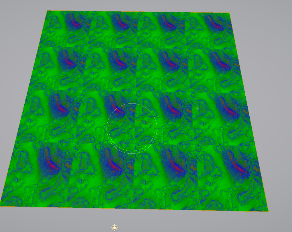
its certainly possible, what are you hoping to accomplish @grand jolt
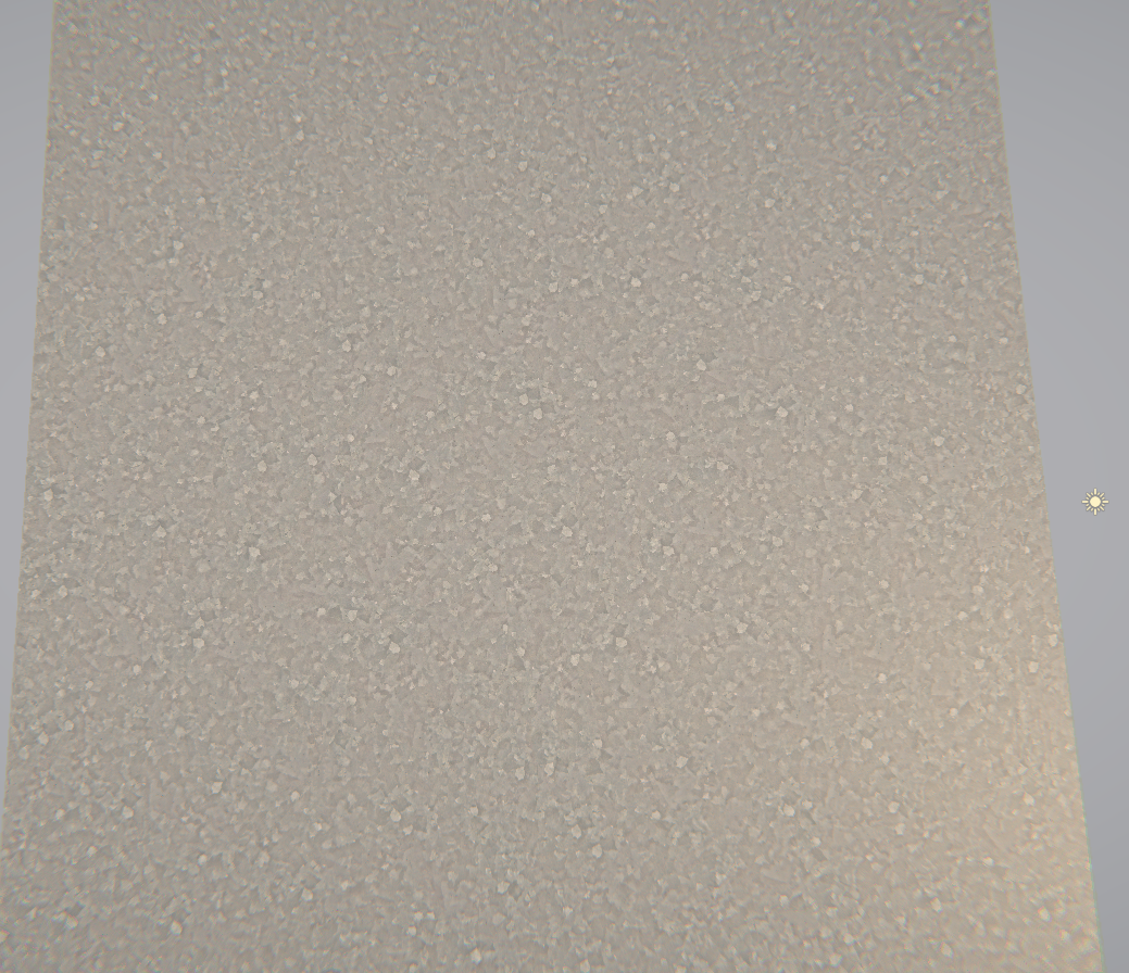
I have a vertical and horizontal seamless texture that I want to tile, but of course if you tile something a lot you notice repeating patterns
I want to reduce or remove this problem
the first idea I had was to rotate each tile a random direction
I've looked into Stochastic Sampling but it looked too difficult, I am still very new to shaders
yeahhhh this is a canonically hard problem in graphics, and one I am not familiar with an easy solution
It's only my 2nd day learning shaders so I am wondering if I am biting off a little more than I can chew
I saw this post: https://forum.unity.com/threads/random-tiling-mask-shader.367166/
Unity Forum
Hi all,
I'm trying to recreate the Random Tiling Mask effect from Unreal engine (as described here) in a shader.
I was able to manage to rotate the...
again it is something possible to do, and the way done there is not bad
creating the mask texture is pretty simple
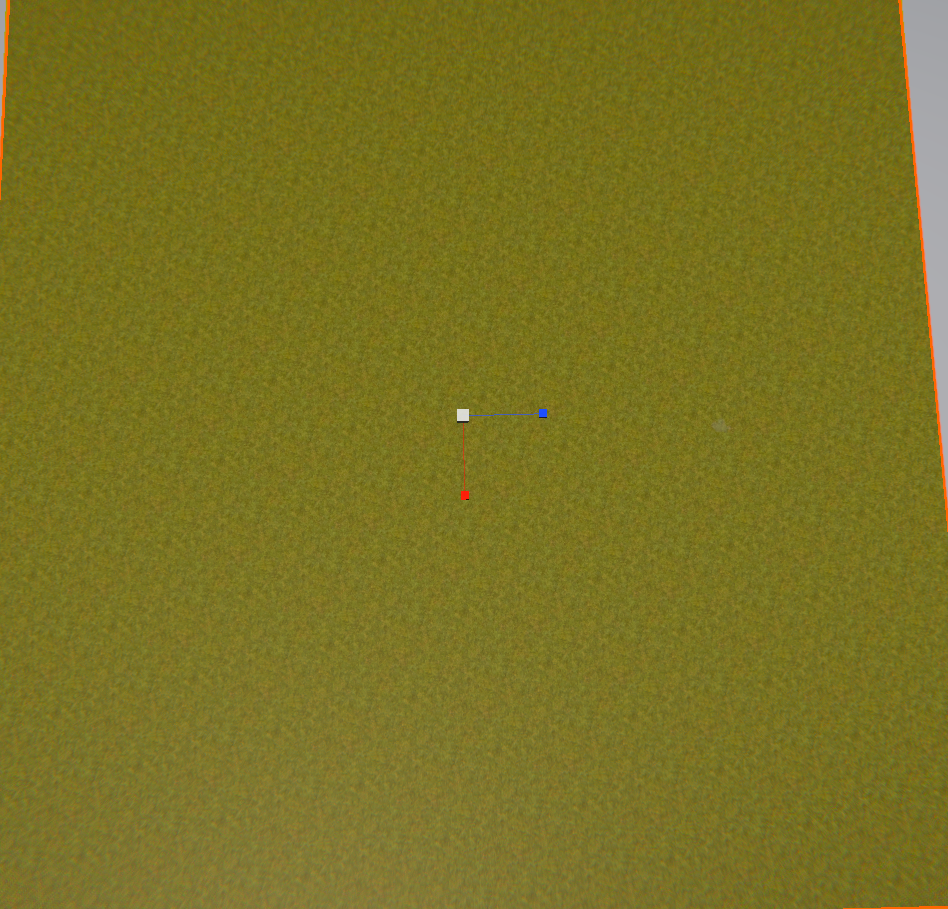
I have a flat plane that is 20x20 and I am trying to control a shader to only render a circle on a certain position on that plane but instead it renders on each quadrant. How would I do this?
I'm using Amplify so I am trying to wrap my ahead around translating the code into Amplify's nodes @simple frost :p
ah okay, I am unfamiliar with all the nodes in Amplify although none of the code here looks to be doing anything too crazy
is there a particular line or chunk you are having issues with?
Well since I am new to shaders in general, a lot of terms are very unfamiliar with me - for example, I have never heard of half2 before
is that a double?
a half2 is a vector of two components, but instead of using floating precision of 32bits, its using 16 (well, maybe it is, half precision is weird in practice)
doubles should be 64 bits, but maybe I am mixing up values
        half rand2 ( half2 coords ) {
            return frac(sin(dot(coords, half2(12.9898,78.233))) * 43758.5453);
        }

        void surf (Input IN, inout SurfaceOutput o) {
            // declare the rotation matrixes in array fo 0, 90, 180 and 270 degrees
            const half2x2 rotMx[4] = { half2x2(1, 0, 0, 1), half2x2(0, 1, -1, 0),
                                       half2x2(-1, 0, 0, -1), half2x2(0, -1, 1, 0) };

            #ifdef _USERANDMASK_ON
                int x = rand2(floor(IN.uv_Tex1)) * 4; // random between 0-3
                half2 uvTex1 = mul(rotMx[x], IN.uv_Tex1); // apply random rotation based on rotation matrix
            #else
                half2 uvTex1 = IN.uv_Tex1; // use unmodifed UVs if _UseRandMask is Off
            #endif

            // use input texture with calculated UVs
            // and using texture derivates ddx and ddy to resolve mip mapping issues
            half4 tex1 = tex2D(_Tex1, uvTex1, ddx(IN.uv_Tex1.xy), ddy(IN.uv_Tex1.xy));

            // send texture data to shader output
            o.Albedo = tex1.rgb;
            o.Alpha = tex1.a;
        }
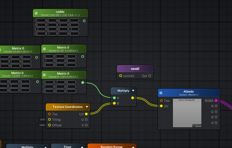
This is the chunk I am trying to translate
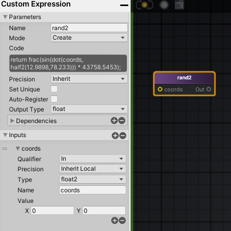
There's a function called "rand2" so I used a custom expression node: https://i.imgur.com/MOP3Pkw.png
sure, how are your math chops?
math chops?
do you mean how good am I at math?
Amplify lets you chose your precision for the custom node
right now it's set to "Inherit" which I don't know what that means
yeah, just cause this is using rotation matricies and ddx/ddy and the like
I am familiar with matricies
inherit means its inheriting the precision it should use from the graph rather than on the node
right
so I probably want it on inherit anyways then
probably, really more comes into play for specific target hardware
In the surf function there's this line
            const half2x2 rotMx[4] = { half2x2(1, 0, 0, 1), half2x2(0, 1, -1, 0),
                                       half2x2(-1, 0, 0, -1), half2x2(0, -1, 1, 0) };
which to me looks like an array of four 4x4 matricies
correct
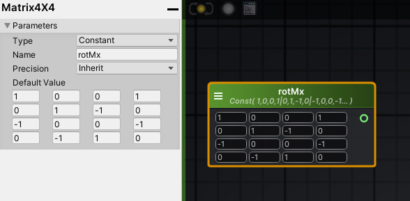
thats a 4x4 matrix though, so youll need to convert each row into a 2x2
if youre just using it to pass in thats fine, but just to keep in mind for matrix selection/multiplication
hmm
Okay so I am confused by the difference
do you mean 2x2 as in
[-][-]
[-][-]
instead of
[-][-][-][-] ?
yes, since youll be multiplying a vec2 against the selected matrix, which will need to be 2x2
I would hope there are different sized matricies, but worst case you can always pad with 1s
no matrix 2x2, so youll pad with 1 on a matrix 3x3
its okay, this was why I was cautioning math knowledge just cause this is a harder problem 🙂
you can construct an equivalent matrix to your 2x2 rotation matrix by adding 0's to the end of every row, and then adding a new row with all 0s but a 1 at the last place
so
1 0
0 1
would become
1 0 0
0 1 0
0 0 1
is that just how the math works out?
yes, and youll need to multiply a vec3 against that matrix, which would be (uv.u, uv.v, 1)
yup
and I need to store them in an array somehow
or just switch based on the mask
ok one second let me make these real quick
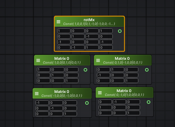
here's the original 4x4 with four 3x3's below it
looks fine to me
Alright
                int x = rand2(floor(IN.uv_Tex1)) * 4; // random between 0-3
                half2 uvTex1 = mul(rotMx[x], IN.uv_Tex1); // apply random rotation based on rotation matrix
            #else
                half2 uvTex1 = IN.uv_Tex1; // use unmodifed UVs if _UseRandMask is Off
            #endif
This part confuses me a lot
int x = rand2(floor(IN.uv_Tex1)) * 4; // random between 0-3
starting with this
apparently that gets a random number between 0 and 3
that is correct
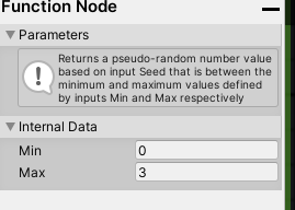
Amplify has a node called "Random Range" which takes in a seed and you can set the min and max value
which you could use as well
So I am not sure if I should just hook up noise to it and set the range between 0 and 3
like this
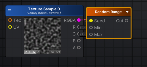
I would pass in the uv perhaps
There's no documentation of this node on their wiki
or, nothing, a default seed should work fine
although you will run into an issue with this
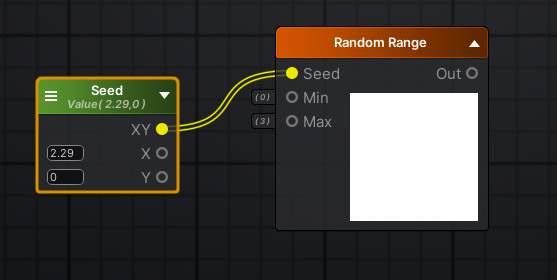
I'll make a vec2 and plug it into the seed input
and make it property so I can change it at runtime
since you need your random value to be consistent over a larger area
If not, then I am guessing all tiles would just have the same rotation?
more like every pixel might have a random rotation
If the seed is left blank, it will likely return the same value for every pixel
For now, I can leave it as adjustable values - if it works then I can just fix it after
not familiar with amplify, figured it uses something inherent like uv but you might know better @regal stag 😄
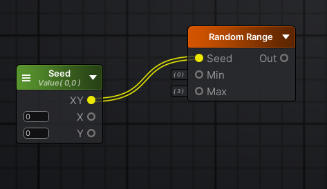
I'm not too familiar with amplify either, but I assume it works similar to the random range node in shadergraph
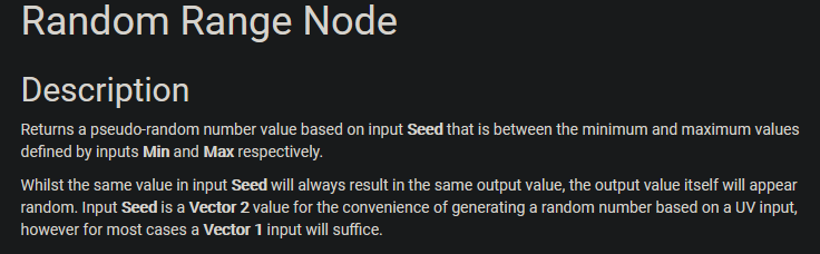
Same inputs too. For an input v2 seed, outputs a value between the min and max. If the seed is the same for each pixel/fragment the output would be the same too.
The nice thing about Amplify is that I can visualize results of nodes
so if I change the values: https://i.imgur.com/8XFII33.png
shadergraph allows that too 😉
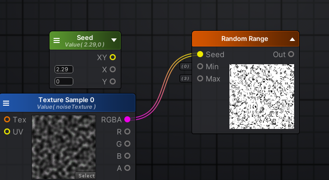
try passing in uv
might be labeled as texcoord

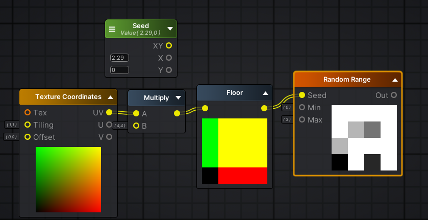
If you want to generate a random number for a number of tiles, it might be easier to do something like,
UV * Value -> Floor -> Random Range.
awesome, so that ~sorta~ looks like the mask we need, but its waaaaay to tiny. We want this
was getting to that @regal stag ;P
Haha
int x = rand2(floor(IN.uv_Tex1)) * 4; // random between 0-3
is that what that line is?
oh
woah
Not sure what floor is doing exactly
rounds down to nearest integer
not color math, just vector math
So the UVs range from 0-1, then multiplied by a constant like 4 in your example, so 0-4. removing decimal values by flooring. That way, a whole tile has the same value.
so I multiplied by x=4, y=4
should the amount I multiply by match how much I tile the texture?
yup yup
The colours are just how the previews work. x = red, y = green
so for example say I tile the texture 25x and 25y
ok that makes sense
half2 uvTex1 = mul(rotMx[x], IN.uv_Tex1); // apply random rotation based on rotation matrix
im assuming mul = multiply
correct, doing a matrix multiply
this is where youll need to pad the texcoord vector with a 1 as well
Okay I am trying to wrap my head around this
since you can only multiply a vector and a matrix if the number of rows matches the length of the vec
x is a random value
and he has an array of matricies
it's easier to understand in code for me
but im not sure how i'd translate that into nodes
I already have 4 rotation matricies ready
just not sure how to make it pick a random one based on the random range I got
you need a branch then, to essentially choose which rotation matrix to use
theyre implicitly doing a branch by having the random number be an index
since not using an array, have to be explicit with the branch
yup
hmm
ok im doing something wrong then
because I assumed if I multiply one of my rotation matricies with the texture, it would rotate it
but its changing colour
i think i might know why though
yes
got it
i hooked up all the matricies and they do indeed rotate properly
so what do you mean by branch exactly?
I think in amplify there's an "If" node?
theyre not great no
which is why the code is trying to avoid it
by using the index
there is indeed if statements in amplify
but they arent the end all either
compilers are a hell of a lot smarter than we are
cyan is typing lol
In shadergraph I know there's a Rotate node that can rotate uvs. I seems to construct a matrix from the sine and cosine of an input float rotation value. Could probably be used to avoid a branch but it probably isn't too bad.
Don't know if amplify has anything similar to this
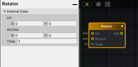
Cool yeah, that looks similar. I'm assuming the time input is a radians value
Instead of using the random number generated as an index to pick a matrix out of an array, you could use that random value as the time input. Would need a bit of tweaking to make it harsh 90 deg rotations though.
Well to be honest
90 degree rotations arent a priority
I can go with random rotations too
In that case, just have the random number be generated between 0 and 2 * Pi, and put it into the Time input on that Rotator
for reference
this was it originally
A guy on the Amplify discord said I can also just define const half2x2 rotMx[4] = { half2x2(1, 0, 0, 1), half2x2(0, 1, -1, 0), half2x2(-1, 0, 0, -1), half2x2(0, -1, 1, 0) }; in a custom expression apparently
Don't know enough about amplify but sounds something like shadergraph's custom function node.
probably
Still just messing around
        half rand2 ( half2 coords ) {
            return frac(sin(dot(coords, half2(12.9898,78.233))) * 43758.5453);
}```I have this as a custom expression and it worked as well when replacing the Random Range node
I imagine that's similar to what the Random Range is doing. I think that's the code used by shadergraph's one too.
Good afternoon everyone! I'm new to the forum here and I have a question that is complicated and potentially confusing (at least I think so), so I'm either going to need A) a lot of patience, or B) a PM with someone from Unity so I don't clutter the feed. I prefer option A so we all get to learn together, but I don't know what the rules here are exactly
I'm going to take a 10 minute break and try some more stuff
Best to just ask the question, but you might not get an answer straight away depending on the complexity and who's around to see it. If you have any large shader code blocks to share you should use hastebin/pastebin/etc.
Here is the situation:
- I'm creating a stencil shader and a lit shader
- The stencil writes to everywhere there are no occluding objects. Essentially a stencil of the background/clear color
- The lit shader is pretty standard/simple but it can't write to the depth buffer for the effect I need.
The problem:
- I assume that since the lit shader doesn't write to the depth buffer, certain depth sensitive post-processes overwrite the values at the fragment locations since they are seen as background
- This is an issue for me because the volumetric fog in my scene is overwriting the fragments where my cubes are at.
After writing it out, it's not actually that complicated I guess, I just didn't think I would be able to phrase it in a way that made sense
Here are some pictures of what is going on. I apologize for the minimal pictures, but I cannot reveal much as per company guidelines
Fog overwriting the cube color
What does the stencil shader have to do with this?
The stencil is going to be used in a different manner
There will be panels that occlude fragments even though the panels are in the distance and the fragment is by the user. So the user can walk around the cube but it will only see the cube where there are no panels in the distance and nothing in the world in between the user and the background
So in the picture above, the cube is in front of the podium and the balcony area, but it is rendered behind it. All other cubes in the scene are sorted and rendered appropriately as well, but they are masked off in a similar way with depth respect of each other
If there is a better way to achieve this effect though, I'm all ears! I'm open to anything at this point
What render pipeline is this in?
HDRP
@crude canyon Is this custom lit shader made in Shader Graph?
Alright I am back
Yes. Admittedly I've not written a lit shader for HDRP before, so I am fairly new to the nomenclature
@crude canyon It's hard to make any suggestions without knowing more about the requirements for this lit shader. Why does it have to have ZWrite Off?
When I have ZWrite on, the geometry of the cube is inserted in the world regardless of my stencil tests and it just turns into a giant grey cube that occludes objects behind it. So maybe you're on to something. Maybe I just need to figure out something with the lighting or passes on my geometry?
I need these cubes to never occlude other objects and only write where the stencil is but they need to be placed in the world appropriately. I know that sounds stupid, but it's the requirement I've been given.
Have you tried making the cube only draw where the stencil is and after everything else has been drawn?
What effect does that have?
Is that something that can easily be done in Shader Graph? I guess you could do it with a renderer feature, but I've only used that in URP.
That's my problem right now is the HDRP pipeline. I don't know how to do something like you mentioned because that's exactly the effect I want
I've just never used HDRP, so I'm not sure whether it has the same "Renderer Feature" thing as URP does. I'm making a quick template project to find out.
If it does, then it should be trivial to do this effect
hmm, anyone used the codeless SRP stuff a bunch? I'm trying to put off fully customizing my SRP but I'm trying to pass material property blocks to an override material, is this even possible?
(URP 7.2.1/2019.3f6)
@crude canyon Looks like they don't have the exact same thing, but they have something similar called "Custom Pass Volume"
But it doesn't have stencil overrides like URP has. Don't know if that's because of some limitation or if it can be easily added in your own custom pass.
Hmm, doesn't look like there's any way to specify it in a custom pass
@grand jolt you should be using seamless textures if you're not already (not sure, and that was a lot to follow). The other thing to do, is to offset the UV's by random amounts like you're doing, but drive it from a seamless texture also. Then scroll that offset texture to slightly jitter the UV lookups to avoid overly-obvious repetition, and/or also mask or overlay a 3rd texture with different speed offsets that distorts color rather than uv.
Just some thoughts, and it's easy to do without getting hung up on recreating an exact other-version. And you can drive it mostly from the art side by changing the textures.
Maybe that's kind of where you ended up, too much to follow. But I've had a lot of luck just inputting a main texture and a few others, with variable scrolling based on something...time or maybe in the case of terrain worldpos.
Thank you @regal stag @simple frost and also @meager pelican
Seamless textures give a very "tiled" look @meager pelican which is why i started this whole thing
Sure, but they won't have seams....(the edges wrap).
Then the random stuff gives you SOME variability. Like Zobash mentioned, it's a universal problem.
Does anyone know how to fix the hole in my shader? I have tried altering all the settings, but nothing seems to fix it. Well, setting the bias to 0 does fix it, but it adds lots of new strange lines.
Sorry for interrupting xD
Usually you use very small values for offset. Try like 0.001 or something. or 0.01...
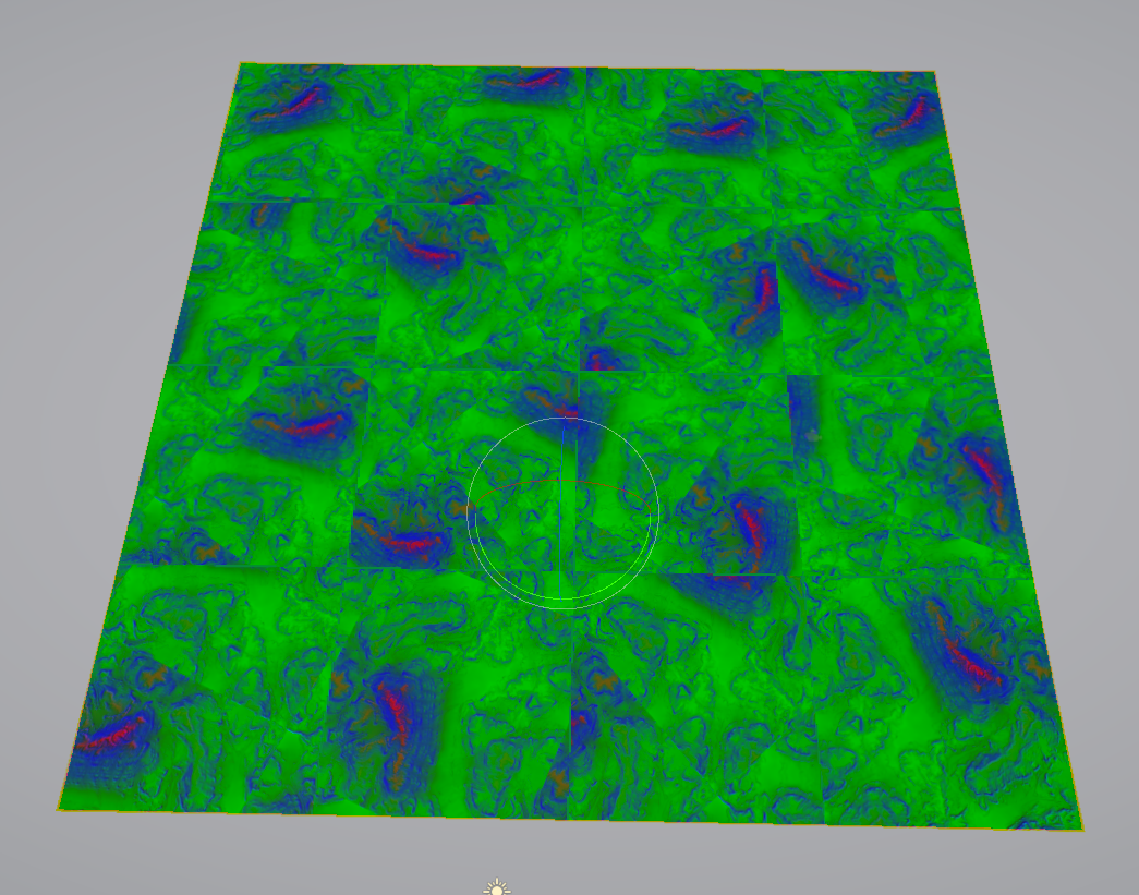
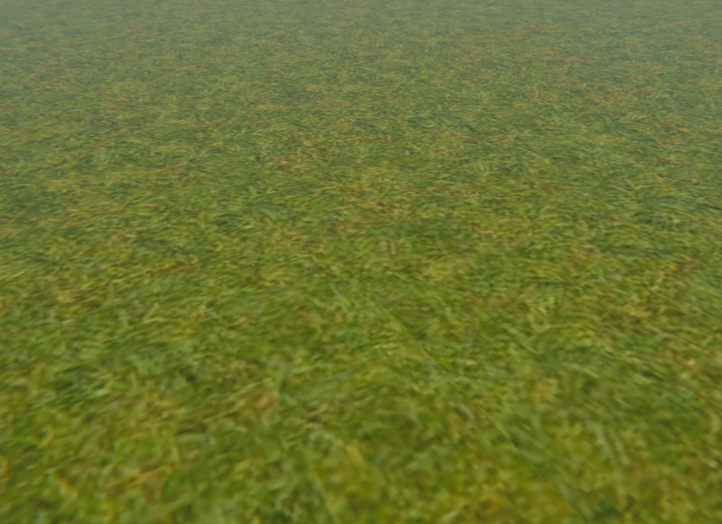
Like for example
this grass has very obvious repetition
but with the shader I just did
it's a lot more random now
Seams and repetition are related, but two different things.
yes, nice.
But the next issue at hand
with random rotation you're going to get some noticeable seams
so I now have to figure out a way to blend these together
Setting the bias to 0.001 doesn't seem to make any difference
@olive mist Did you slide it around between like say 0.1 and 0.001 and see what happened?
Yeah
OK. I yield.
@low lichen Thanks for all the help so far! I was in a meeting for a second there. Yeah, I need to get lighting functional and Fog off. If I can get that figured out with my HDRP shader, I'd be a happy dude
That's why I thought distorting the UV's linearly rather than rotating might help. That and also varying color a tad, with a different random.
@crude canyon I think it can be done with the Custom Pass Volume. Their DrawRenderer pass just doesn't expose stencil settings like URP does, but I don't see why it doesn't. I'm now trying to make my own DrawRenderer pass with stencil settings exposed. The way it would work then is the lit cube would be on its own layer which isn't in the camera's culling mask, but is instead drawn by this custom pass where the stencil settings have been overridden. Then it doesn't have to be defined in the shader itself and you can keep using Shader Graph for it.
And the custom pass can also define when it draws this layer, so you'd want to do that after everything else
@crude canyon I've been testing this Custom Pass Volume, but not quite getting the hang of it. It has some differences from custom passes in URP. So I guess the other option would be to convert the cube lit shader graph to shader code by getting the generated code from Shader Graph and manually adding the stencil part.
You'd have to do this manually any time you want to make changes to the graph, which sucks
@grand jolt blending between tiles will be difficult without either multiple texture samples or figuring out some sort of derivative to your equation
@low lichen I just got the final product working with lighting. I haven't checked fog yet, but I basically just generated a shader with the node graph and manually edited all of the passes
This is the result. It actually looks pretty awesome in VR, but it is hard to explain it in chat.
@low lichen Thanks for taking the time to walk through this with me! Just having someone to ping ideas off of helped immensely! I'm a believer in this discord now for sure!
@crude canyon Glad to see you figured it out. How has HDRP been working out for you in VR? Are you using the Forward Only mode to get MSAA?
We're using URP for our next VR game. Didn't think HDRP was any good for VR, because of performance and deferred (before I knew HDRP also had forward).
@low lichen To be fair, I'm using it for a DoD application and our target hardware is a Ryzen Core with a 2080 Ti, so performance isn't my main concern. Since that's the only hardware I have right now, I can't give you a realistic benchmark for HDRP VR. I will say that I wouldn't use HDRP right now if I didn't start down this path already. Our artists tend to hate it and I don't have enough time in a day to get around to exposing more of the shader in editor in a way the Artists want to work with it. So, they just don't use it currently. I'm hoping the Amplify shader will help them with shader creation so they can start iterating on materials with me
perf between hdrp deferred and forward is about the same, can get small gains on either way depending how you use it
in regular use, deferred can be tad faster even
if you target only VR and it's not some high end visualization, URP is way better pick for VR
Shadows seem to be rendered wrong when using URP and shadergraph vertex displacement
thats a world rounding shader, and they seem to be drawn like if the model was never displaced
is the shadow render for some reason not using the displacement? or could it be using the for the camera position, the light position, and thus, curving the world in a wrong way?
You can check the frame debugger to see what the depth pre-pass and the shadow map look like
animal crossing vibes
ok yeah its the second thing what is happening
the world is being rounded by the light
I need a way to tell the shader to use the camera camera position, not the current camera position
with world rounding shader
without
and here it is more obvious
I set the light to have no rotation
all those 3 objects are at the same y level, and the same distance to the camera
@slender birch You could pass it to the shader with a global shader variable: Shader.SetGlobalVector
will try, thanks
if anyone was curious you can indeed use a material block property to apply to an override shader in a separate SRP pass you just have to not make the noob mistake of not initializing the property block
do I need to use the property reference or the name I give it?
because neither seems to be working
You need to use the property's reference in shadergraph, and it needs to not be exposed for SetGlobalVector
Alright
I think I have something I am happy with
Here's the result before

and after
and up-close
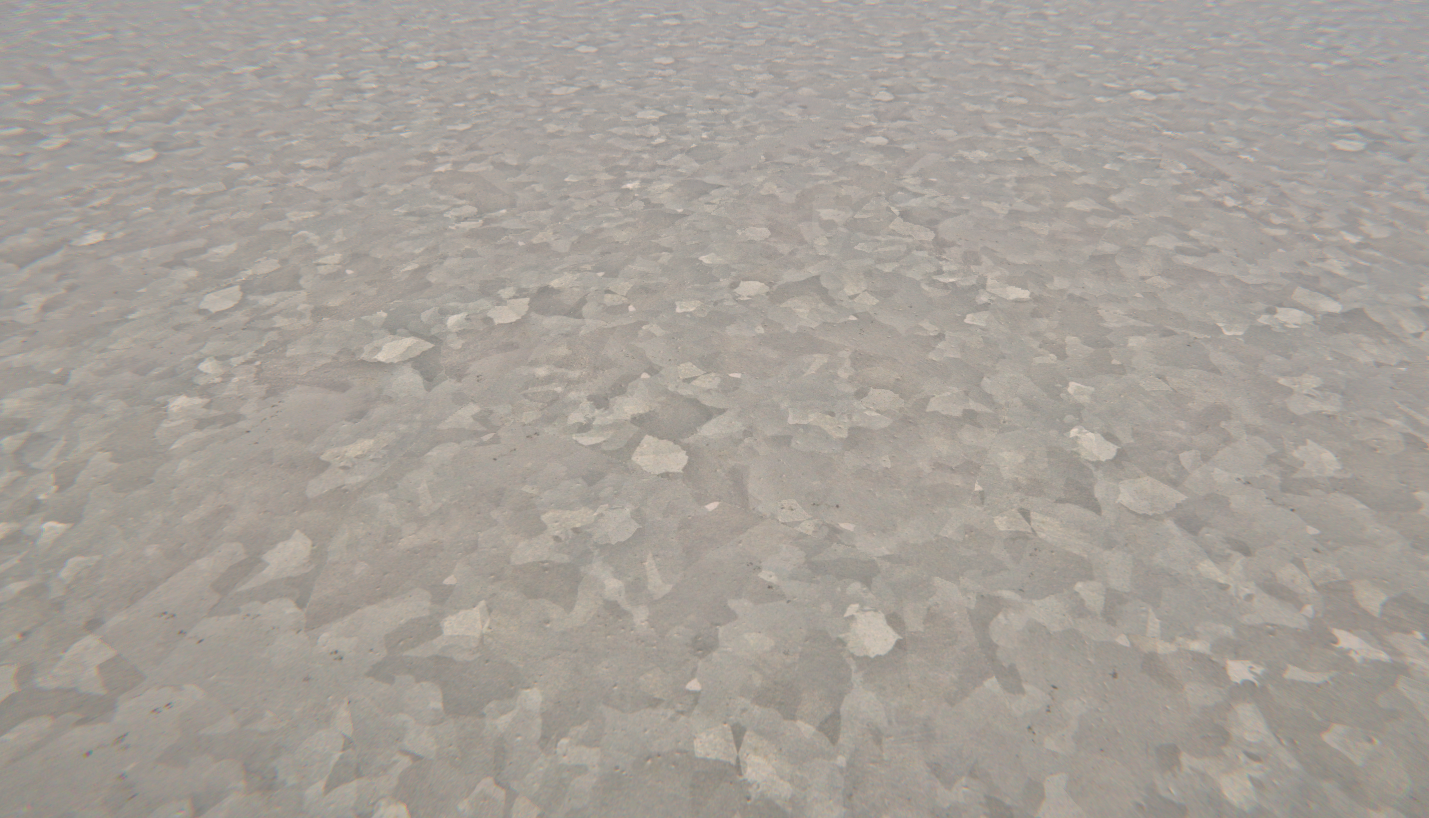
It's basically a combination of tile rotation, bias, a mosaic noise modifier, and a cross blend between a flipped sample texture
wonder if the Unity Machine Learning stuff will make Wang tiles super accessible
ok that seems to have accomplished nothing at all
so I was wrong
the shadow render using the light pos isnt what is causing the fuckery
The shadow map is supposed to be rendered from the light's point of view
I thought the issue was that you weren't getting the right curve in the shadow map because the curve is calculated based on the position of the camera, which in the shadow map isn't the position of the camera but the position of the light.
lookin good @grand jolt
wait what
yes it worked
I guess I didnt save the shader or something
but it did work
nice
glad to have helped, still think you should be using shadergraph tho 😉
not biased lol
havent tried it yet but I did pay for Amplify
back then a team I was working with got me a license
I only used a bit though
but that was like 3 years ago
so i forgot a lot about how to work with it
yeah I imagine it comes back quick tho
ok so, it did work
but, what the fuck is that
why is there a shadow
I have the light set to not cast shadows
if I dissable shadows, its still there
its a shadow, yet its not a shadow
first picture is with shadows dissabled
with shadow casts dissabled
@slender birch Is it the shaded part of the ground? As in, it's getting darker as the surface normal starts facing away from the light direciton.
yes
oh
yea
lmao
makes sense
ok so I know how to fix that
I just have to completelly yeet my normal fix code
because it works too well
and I actually didnt need it xD
I think this is it, thats all
this fucking shader is finally done
time to plagiarice animal crossing
or something
I have a Regular Polygon Mesh (any amount of verticies). I would like to put an outline on it. I have never worked with shaders but is this something that I can do with them?
yeah, you can write a two pass shader which renders it as outline color and scale it slightly, then the second pass draws as normal.
should be a pretty good intro to shaders, actually.
sure, if your on standard pipeline.
hey guys anyone know a way to access grab pass using URP, specifically the 2d renderer?
In my shader graph I have a reference to the x, y, z world position as the center for a box, then I have each faces direction, and I also parse in the x, y, z scale as a volume to cut-out any object which leaves the box, it works perfectly, except for when dealing with rotations. I did a sort of work-around for rotations of the box but it doesn't work very well and breaks in some circumstances.
Are there any nodes or methods I could use to have the box projection in the shader follow the rotation of the object??
@fluid pollen If you change your space for the XYZ values to object space it should stay aligned to the object
Half answering my own question but the URP , under general lets you enable OpaqueTexture which seems to work as the GrabPass.
haven't actually tested if this works just yet :p
yeah if you aren't doing VR it definitely does work, there are a few caveats but pretty close
do you happen to the know the caveats off the top of your head?
I believe it is all post processed already so you can't get it before then, there is no depth texture unless you are also passing that
interesting, i can see how that could limit some things. thanks for the heads up.
the only other big thing I have not poked a bunch is if you are customizing your RP what exactly gets passed to shaders
hmm and now I'm trying to remember what it does with transparencies
yeah tbh im not much a pipelines developer so id rather not have to make my own custom render pipeline
according to the unity doc pages the _CameraOpaqueTexture only works with transparent shaders
which makes sense for the context
yeah so I think that is what happens, it does all the opaques and I think it is pre-post processing, sorry for my confusion
no yeah i get what you mean
it happens before the post processing but after the opaque stuff gets renderered
I have an image texture with some transparency. It's in a material attached to a flat plane. I want to be able to render it so that the front appears as normal, but the backface appears black except in areas with transparency. How might I do this?
I'm having some issues with Shader Graph for 2D.. Is this a good place to ask?
I've been asking some questions here and would also like to know as I dont want to spam/annoy others
yeah, i just jumped on this server for the first time... don't want to start posting all over the place!
I just started messing with the Shader Graph, dropped a Sample Texture 2D node on the blackboard and attached a 2d texture with transparency... In the little preview, the transparent regions are all red... Not sure what's going on.
can you send a pic of your current setup?
also what are you trying to accomplish? just render a basic sprite lit shader?
the previews don't show transparency, but is that actually an issue?
Or is it red in the actual output
For the most part, the output works...But when I do an Add operation to add a green edge, it renders as yellow...So I fee llke somehow there's some red bleeding in... Yeah, I can take a picture!
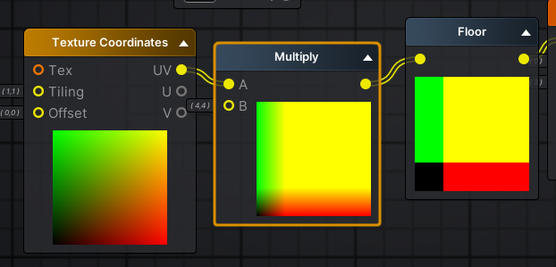
Trying to do an outline shader. My green is turning yellow. Because of the red?
This is the texture
But why is all that red bleeding in? It should be transparent, so there should be no red for the green to add to on the left edge.
the Multiply node looks good
because transparency is only in the alpha channel
the rest is filled with whatever the image is saved out as, and that with pngs will be a filled version of the outer ranges of the alpha
depending on what saved it out
it looks fine until you literally add the green onto the red
ah! so my texture coming in has something wrong with the alpha?
No
that's just how alpha works
there is absolutely nothing wrong except you choosing to use add
(btw, I'm just following along with this video: https://www.youtube.com/watch?v=FvQFhkS90nI around 4:33)

✅ Get the Project files and Utilities at https://unitycodemonkey.com/video.php?v=FvQFhkS90nI
Let's make a Outline Effect Shader to apply to our Sprites in Shader Graph!
Check out the entire Shader Graph Tutorials Playlist
https://www.youtube.com/playlist?list=PLzDRvYVwl53tpvp...
his sprites have black outlines, so his background is black
but as you can see, it bleeds where it isn't black
the Add logic is wrong and won't work in all use cases
okay, now that makes sense!
unless you wanted to multiply the color by the alpha before doing all this, but I suspect you would get black fringing around the alpha'd areas
so for textures with transparent alpha, i wonder if there's just a better way to do an outline? or would it be easier to prep the textures differently?
i feel like my texture with transparency is the right way to go
just think about the type of blend you're doing instead of using an Add. The blend node's easy to use and very flexible
heh, so now my Preview node, Main Preview, and Scene are all showing different things...
I have something that works nicely in the Preview window .. Just used a channel mask and a multiply to get a nice clean extraction of the image .. Then, I can get away with a straight Add. Looks great in the Shader Graph! But, the Main Preview is bad and it renders weird in the Scene.
you would need to add the alphas of both sampled textures together
also just generally, numbers can go outside 0-1, the Saturate node is used to clamp them if you run into that issue
hey, so I applied an default unlit shader to a 2D sprite and it turned invisible, does anyone know what's up with that?
Oh I realized whats up!
Its somehow messing with the depth of the object
the sorting layer and such
what can I do to fix this?
Like it shows if theres nothing at all in the scene
but the moment something intersects, no matter the sorting layer, it gets obstructed
hi guys so there's 4 bottle (from most front)
semi transparent, solid, semi transparent, solid.
why it's go all through like that?, use shader graph, transparent, already try all blending mode but none of them satisfy me, use LWRP...
hi there. After building our project, in the log, we got : WARNING: Shader Unsupported: 'HDRP/Unlit' - All passes removed
WARNING: Shader Did you use #pragma only_renderers and omit this platform?
Any clue to remove that ?
@delicate badger I'm using HDRP/Unlit on 2020.1.05b, through RenderMesh, no problem. Are you on URP? LWRP? Built-in? Custom? Did you edit the code for the shader? That error is telling you that you're on the wrong rendering pipeline for that. Note that HDRP/Unlit is not shadergraph.
@grand jolt , we are on HDRP 7.1 on Unity 2019.3.6f
We don't edit the code for the Shader no :/
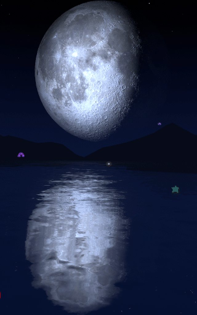
Been trying out alot of water shaders but none of them seem to produce the effect I want (object or skybox reflections/refraction) . I'm looking for a water shader that creates this kind of effect. Or any shader that i can pair with the water shaders to create this effect
https://i.imgur.com/6Ms95xh.gifv
Do the URP/LWRP shaders work with HDRP? Looking through examples and a lot of them are URP but we are using HDRP
@grand jolt that looks like screenspace reflections best as I can tell, could use planar reflections but idk if youd be able to get as much detail on a large body of water like that
Is it possible to generate a shadow on a texture with a shader? quite new to shaders still so I'm not sure
@sonic plinth what are you trying to accomplish? There are some techniques for faking smaller shadows on materials, usually in things that use POM or faked heightmaps
yeah, pretty much faking shadows
Shadows cast by what? The object itself?
what do you mean?
What shadows are you trying to "generate"?
so on the texture there can be areas where a 16x16 grid of pixels is filled in, and i want to generate shadows on that
pretty much my games "world" is a texture
Can you post an example screenshot, maybe from another game that does this effect you want?
I dont really know any game that does anything like what im doing
I don't know what you want, so unless you can explain it better, I can't help
Does anyone know how to expose this in shader graph ?
Double sided get auto exposed but not Receive Decals 😢
if you are wanting to make a decent looking* terrain, are things like CTS necessary? is URP enough to get the job done with some time and patience?
@grand jolt I believe my shader might be able to do what you want. It does planar reflections and can distort that reflection.
I could pm you the store link if you'd like, you can tag me
Hey. So I want to have an per instance array of X elements in shader, 5 floats total per element, that will change during runtime. What is the way to go about with this?
@grand jolt you can create your own via shadergraph, I've done just that and used the planar reflections from Attack boat demo. Reflections, refraction and distortion was actually very simple to implement.
If using standard renderer, Crest git version is free and will do that sort of effect too.
@hushed urchin So each instance might have any number of elements and the number of elements can change at runtime?
The max number will be set at start, but it could be any number.
@hushed urchin You have to define the same array length for each instance, but you can have a separate per-instance integer for the actual count.
But 5 floats per element makes that a bit tough. Either you have one float4 array and another float array and read them both, or you use a buffer. But I don't think buffers can be instanced, like textures.
OK, so we're back to "GPU Instancing" again.
@hushed urchin is this standard pipeline or SRP?
😄
hdrp
OK, now out of my element. With standard, you'd just have an array of 5 floats per instance. Or stuff some floats into color data or whatever.
But with SRP, they don't support instancing as I understand it.
I think they also don't_support_it in HDRP. And that makes using a buffer, like @low lichen is saying, more attractive, IF someone in unity can tell us how to track some form of instance index so we could index into the dang buffer @simple frost . Otherwise, IDK how we're suppose to stuff instance specific data into something using the SRP methodology.
But its probably because I'm admittedly dense.
And define/use the buffer in SG is a problem as I understand it.
SRP supports instancing just fine. It's the optional SRP Batcher that won't automatically batch anything with instancing. And I said before that Shader Graph doesn't support instancing, but that isn't correct, you just can't define properties as instanced properties (I think)
@hushed urchin Are you using Shader Graph to make this shader?
OK, so you can get instanced data, but not batching.
That's almost useless. But OK, better than nothing.
Hmm.. Yeah, I started using shader graph, but I can work with shaders when it restricts me
@meager pelican Don't you mean the opposite?
You can't get instanced data because you can't define properties as instanced
Uh, you said this SRP supports instancing just fine.
But if you don't use the SRP Batcher and the material has GPU instancing checked, I'm sure it will batch those with instancing.
And it's just Shader Graph that has this limitation
@low lichen I believe you are correct, double checking some code now
If you're using SRP Batcher, it won't automatically batch anything with instancing. If you're not using it, batching will behave the same way it does in the standard pipeline
But if you "don't use the SRP batcher" then how do you get batching just fine?
SRP Batcher is just an optional batcher that batches things differently and is only available if you're using an SRP.
SRP doesn't need to use the SRP Batcher
So I can put a fixed array size in the shader, buffers can be instanced in directx - not sure if you can put a fixed size array in them though, or if that is even a good idea. I see that hybrid renderer V2 has Instanced properties for shader graph, but yeah. It stops for me there because they don't support anything like loops or arrays except for texture2d.
It's optional
OK, so there's some other "default SRP batcher" that batches that isn't THE "SRP Batcher"? lol
Yes and I think it's just the same batching behavior as the built-in render pipeline has
But yeah, maybe will have 30 entities with the shader or something.
That's not overly bad. Not like it's 30,000 or 3,000.
So It doesn't matter if you lose batching (and you may not). So it's a matter of getting instancing for your 5 floats?
I don't need "per instance" I just want it per instance 😛
I think what @low lichen is getting to, and what I'm discussing/learning...is that you CAN get what you want here.
And it's more like 25 floats (5 each element)
OK, 25 floats.
So you don't need to have these draw calls batched into one instanced call?
Not really no.
He's only got maybe 30 of em. Meh.
So the element count per instance doesn't change. I think you could read a buffer using a custom function node.
That seems like the best solution since buffers can be any struct
@low lichen confirmed that, something thats on our roadmap I believe but a workaround you can do at least right now is copy the created shader from shadergraph and add in the correct per render instance decorator to the properties
And then he needs and index to each object
If you have one long buffer containing the elements of all the objects and set that to a global shader variable, you should be able to get that in a custom function without needing to define it in the shader properties.
Then yeah, you just need the start index for each instance and the count.
So you CAN declare a StructureBuffer to SG using a shader global? Good to know. That's me being out of date I guess. Sorry.
I haven't tested it, but I've defined other global variables in a custom function node and that works, so I don't see why buffers shouldn't work.
@hushed urchin If you're using the SRP Batcher, then you can make full use of it by creating a new material instance for each object and only setting the start index and count properties once at startup
is there a way in the particle system in the color over lifetime module to add a third color ?

should just be able to click to add one
Yes, it's a gradient. You can have many colors
ahhh thx @simple frost and @meager pelican you have to be very specific on where to click otherwise it wont work 😄
Zobash, FYI, I'm not at all trashing SG BTW. It's just that IDK how to get around some of this stuff. It's new, and will evolve. Keep up the good work. 🙂
hahaha all good @meager pelican 🙂
So is it possible to make a loop in SG? 🧐 I basically want to loop over these elements in the buffer use my shaderSubGraph and max() over all the outputs to add to final stuff.
@hushed urchin You can in a custom function, I assume
Hmm yeah, pixelshader. It's basically a shield shader, I feed in the local hit positions + time + strength, and want the max alpha of each point to summerize to the pixel alpha.
So you're generating a shield. And you have xyz location, timing data, and strength...(that's the 5 floats) x maybe 5 simultaneous hits at one time, giving 25 floats per "thing".
correct
That's a little less bad, that's only 5 iterations of a float5 structure. (really float3, float, float). Like MS said you can do that in a custom node to read the structured buffer.
You often want to pad structured buffers to maximize memory access to sizes of float4 multiples though. If you can manage to 'pack' the timing and the intensity into one float (think the integer part and the decimal part as two things) that might pay off.
But I'd try it both ways, as it might not even matter for 30 of em.
Hmm yeah. I could just go with plain plain float buffer and calculate the offsets. The only thing now is I fail to see how I would be able to call my subgraph from the custom function.
@devout quarry Do send me a link to your shader, that would be nice!
@thick fulcrum I haven't done much with shader graph before, but I do have experience with nodes from blender and substance,
Is there a tutorial or a guide that you referenced from?
@simple frost I know what screenspace reflections are, but I don't quite know how to make them. :<
Thank you! ❤️
Just curious but do you need to use the custom function on the texture vs. just letting the normal samplers generate a color for you?
ah, i've seen that bug before. we have it filed somewhere. it's actually that the generated code is sanitizing names that it shouldn't. it's stripping out the _ . try using colortex in the string box for your function instead of color_tex
how mush cost "if" about "mult vector3*vector3" may be anyone have tables with this info?
so I think I found a bug (reported it) in that the "Is Front Face" node in Shader Graph seems to always return false in a VFX Shader Graph (using URP 7.3.1)
anyone have any other ideas about how to test if its a front or back face?
@stone sandal as i understand shader graph convert to https://docs.unity3d.com/Packages/com.unity.shadergraph@6.7/manual/Transform-Node.htmllike this page code? any info about coding without graph?
Hello. I'm having problems rendering a circle on top of my wave plane. I want the circle to be static from an orthographic perspective as shown on the right red plane. Can someone help me out?
@fluid lion Are you just measuring a distance to the point to draw the circle? Should just be fine then to flatten any point to the plane that you have your waves along
Yes. This is the section of the shader that does this.
just delete the part that adds z^2 to circle
if the planes are facing the z direction
so changes in the z-position of the vertices won't affect the circle shape
Unity Forum
I wan't to blend pics using the formula: srcAlphascrColor+dstAlphadstColor
But there isn't any blend mode fit to it. So I want to use GrabPass in...
if you want circle on the screen
oh i see in the gif that your plane is facing the y direction so remove the y^2 part instead
That worked. Thanks a lot.
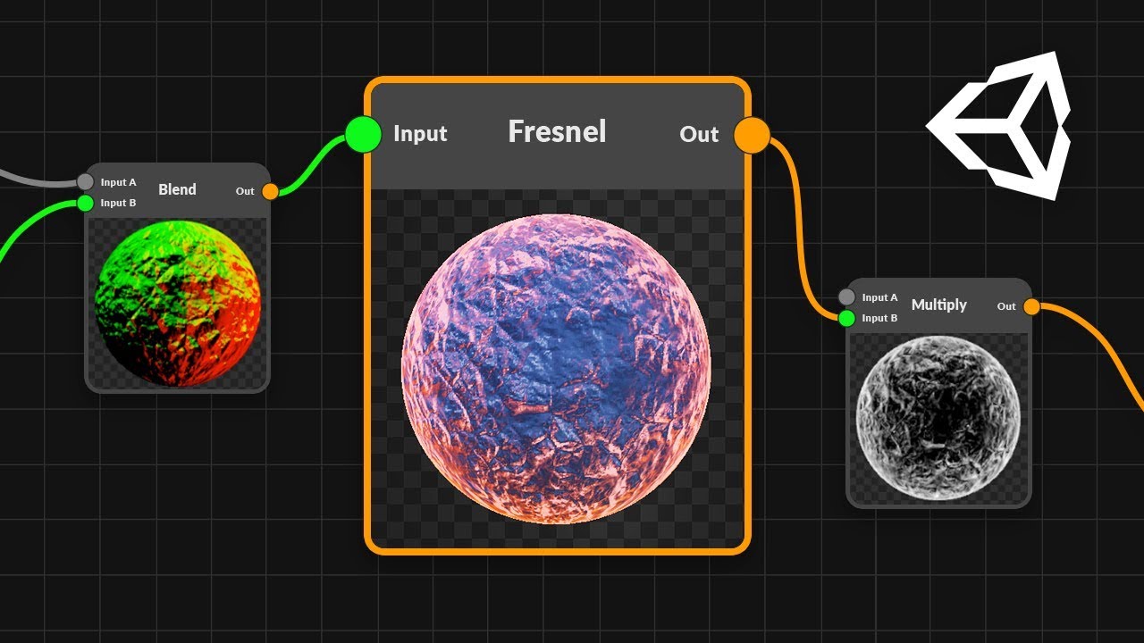
hello, how can I prevent the shadergraph fresnel effect to move?
wait, will send a gif
do you see that small black hole inside? how can I prevent the fresnel effect to do that?
I want it to be static
going to have the best luck painting an effect texture
hey does anyone know if shader graph has any nodes for accessing the Stencil? (working in URP + 2D Renderer btw)
what's the difference between UnityObjectToClipPos and UnityObjectToViewPos?
hi there. After building our project, in the log, we got : WARNING: Shader Unsupported: 'HDRP/Unlit' - All passes removed
WARNING: Shader Did you use #pragma only_renderers and omit this platform?
Any clue to remove that
My vertex displacement is working in the editor but not in game. Why is that?
Are you doing any fancy calculation for the displacement that might involve data that is innactive in game ?
what's the difference between UnityObjectToClipPos and UnityObjectToViewPos?
@fluid lion
OK, so when you 'look around' with the camera, what you're really doing is rotating then entire world around to conform to "you" (the camera). So Object to ViewPos is rotating the world to the view's perspective. However, that doesn't mean the object is visible, it could still be behind you, for example.
There's model, veiw, and projection matrices. The model matrix transforms the mesh from local space to world space. The view matrix transforms to the camera's view space (rotates the world around)...and the projection is from camera space to screen space (projects it all onto a 2d space for you to view).
So, the first one is basically MVP (clip space is for vertex shader, screen space for frag if you work out the pixel math...there's a macro for that too, there's difference with the automatic perspective divide but that's a bit much right now.)
The 2nd one is basically MV...it stops at view space. So it's world-position rotated into the camera's frame of reference.
Clip space (the normal output of the vertex shader, without a perspective divide done during rasterization) is basically -1 to +1 ranges. Anything that falls outside of that is "clipped" hence the name.
@fluid lion Another good resource for understanding the spaces and why the changes between spaces happen is https://learnopengl.com/Getting-started/Coordinate-Systems
Learn OpenGL . com provides good and clear modern 3.3+ OpenGL tutorials with clear examples. A great resource to learn modern OpenGL aimed at beginners.
so theres no built in shaders taht support the crossfade out of the box ?
how would you go about making a shader in shadergraph that supports the lod group crossfade ?
They should with LODGroups if I remember correctly
i dont think the built in ones do you have to make your own and make it handle this unity_LODFade variable
i just managed to make one in shadergraph though
is there a way to use one of the built in shaders as a base like the URP/lit shader for example and just modify it ?
if you mean in shadergraph no, graphs output their own shaders which are compatible with the SRP but not exactly like one of the SRP/lit shaders
oh well thats annoying that the default shaders dont crossfade
in Shader Graph Custom Function node, there's an option to return a Texture 2D; what type should my out parameter be to actually make this work?
I tried this but it gave an error ```
Texture2D _Test;
void Forward_float(out Texture2D Out)
{
Out = _Test;
}
the preview shader can't handle that type, I'm certain that's the error you're getting
try having two out parameters and make the first one a vector type that just returns 0
we have a bug filed to update the error handling and documentation for this
that worked, thanks!
Hi ! I have done a 3D model (Low poly + Normal Map ) and I'm trying to achieve a vfx with a shadergraph based on the 3D model. Is there a way to influence the fresnel effect with the normal map ? Or am I doomed to only use the low poly model ?
a really simple way is t just multiply the fresnel by the sampled normal map channel. just multiply by the r and g channel and add together again to keep a black and white vector, like this
you can also use a normal blend
and blend the normal vector with the normal texture
Oh ! It could works ! I will try this tomorrow.
@simple frost U plug this on the final Master node ? or on the fresnel effect directly ?
Ok thx ! I will try this too ! 🙂
yeah just depends on the effect you want
I'm trying to essentially recreate the Render Objects render feature, but draw to an offscreen render target rather than to the screen. I think I've recreated most of the parts of it correctly, but I'm not sure about what ShaderTagId I'm supposed to pass in to CreateDrawingSettings in my ScriptableRenderPass class. From what I've gathered, it's supposed to be LightMode tag in the shader being used, but I'm not sure how to make this work automatically for arbitrary Shader Graph shaders, like how Render Objects does.
So how does Render Objects figure out which pass to use if none is provided?
You can just check the RenderObjects source code
where is that located? I couldn't find it
Locally it's in YourUnityProject/Library/PackageCache
You can also find it on GitHub

GitHub
Unity Graphics - Including Scriptable Render Pipeline - Unity-Technologies/Graphics
I see, thank you
Hi, does anybody know how to write urp shader for unity tree creator?
@frank steppe
@desert pumice posted a link Tuesday to this about LOD's and I found it interesting. The performance benefit is minimal or even detrimental for more than a couple/few levels. You may find that your LOD's nearly self-fade at distance, since having them mid-way isn't really very beneficial. Of course, YMMV, but I'd test it out.
https://forum.unity.com/threads/psa-a-general-rant-on-model-lods.859201/#post-5698981
That's not to say you can't also cross-fade them, but it might not matter much.
Unity Forum
A public service announcement about modeling mesh LODs.
You are:
Usually making too many LODs
Usually introducing pop-in with them
Usually wasting...
i see, you mean maybe only like 2 lods , and the second one just transitions when its really far away so it wont be noticed at all ?
Right, but read his article and try it out for your use case. 2 being the "real" one and the lower-poly one at distance.
That's so useful, thanks a lot
Thanks to him/them in the post.
right i see thanks
My vertex displacement moves whenever I rotate either view in the editor or game. I have no idea what is going on.
Hey guys, is anyone aware of why this happens? https://answers.unity.com/questions/1489551/applying-a-shader-stretches-the-sprite.html
Unity is the ultimate game development platform. Use Unity to build high-quality 3D and 2D games, deploy them across mobile, desktop, VR/AR, consoles or the Web, and connect with loyal and enthusiastic players and customers.
I have the same issue with my game, and haven't been able to find a solution anywhere
Hey, I'm trying to learn about OpenGL shaders externally for my unity game and I ran into this problem. I don't get why I'm getting a linking error, both variables are named the exact same.
I think you spell vulkan V.u.l.k.a.n. not o.p.e.n.g.l.
Does anyone know why same shader will behave differently on the .obj and .fbx formats of the same model?
Hi all, does anyone know a way to produce an occluded Xray effect using code and shaders like here https://www.youtube.com/watch?v=rL7VUeZzRyQ. I have been experimenting with an open source project for awhile but I haven't been able to find a solution. https://github.com/cakeslice/Outline-Effect/

► Outlines Tutorial: read here for the topics timings
In this tutorial you'll learn how to create an outline post process in Unreal Engine 4 to show objects behind walls.
Topics:
0:00 - Intro: what we're gonna do
1:04 - Project and objects requirements
2:44 - Post process ma...

GitHub
Outline Image Effect for Unity. Contribute to cakeslice/Outline-Effect development by creating an account on GitHub.
WHY ARE SHADERS SOOOO CONFUSING
I'm trying to figure out how to create a surface shader with a step ramp type effect using this algorithm,
= Lerp(0.5,1,ceil(x * 4 + 0.25) / 4
Hi. not really sure what type of a question this is so I will ask here. So I followed some terrain generation tutorial, terrain is generated from perlin noise, it's split into chunks which are shown only when player is near etc. Every chunk has it's own mesh. Texture on the mesh is added via shader depending on height of the terrain, so I have water, grass, mountains etc and I can change textures and their start heights via editor. So my question is: what do I have to do to be able to apply different shader to , for example water. Currently my water is only a flat, plain texture and I would like to improve on that. Should I somehow cut out mesh where water texture is located, create different mesh with different material, or maybe create another mesh on top of that one? What I am trying to accomplish is to have water animated by shader instead of just texture on top of my terrain. And in the future, grass affected by different shader etc. Shader used for applying textures to terrain is currently "legacy" one, and I would like to use LWRP one to make water shader. Thanks in advance!
Hey,
I am trying to create a visual effect where I would have multiple (from tens to a hundred) quads. Optimally quads could be drawn as billboards toward the camera. Quads will have a texture with only alpha channel where it represents transparency. They also have a tint color and alpha cut threshold. Quads need to have physical like abilities like position, and velocity.
What I want to do is to "fuse" the quads visually from alpha (additive alpha blending) so that in close proximity they are fused together, something like a metaball would do but without a distance function, and then color all the fused pixels with tint color to become opaque where alpha cut would cut the rest of the quad pixels out.
Obvious solution would be to do this with particle system and a matching shader, but I am stuck with additive alpha blending. I have a fragment shader with cutout but how I understand blending instruction blending is based on what's the the color buffer. So if I want to fuse only my particles how can I separate this "layer" from the rest of the scene?
I have tried multipass shaders and what not, but my concern is that I have not understod how blending can be done or is done in unity. I know I could write a compute shader and create a texture with that shader and render the texture to the camera and then it would be a "simulation" that happens only on that layer / texture. But is there any other way, like the one I have tried with particle system and regular fragment shader?
All help is appreciated! Thanks!
hi there. After building our project, in the log, we got : WARNING: Shader Unsupported: 'HDRP/Unlit' - All passes removed
WARNING: Shader Did you use #pragma only_renderers and omit this platform?
Any clue to remove that ?
Can you send more of the log information ?
So anyone know if there is a way to call subgraph from custom function?
@amber saffron there is no more data 🙂
but there is the same issue if you create a emptyHDRP on the 2019.3.6 on HDRP 7.1 and 7.3
I update Unity to 2019.3.10 and i will try, the I will switch to 2020
Can anyone try to answer my question? If it's badly explained, i can try and do it better
@delicate badger What is your target platform you are building? Have you used #pragma only_renders directive to compile the shader for certain renderers like d3d11 ?
I can't then figure anything else than an instruction in the shader causing this to be excluded. So if shader isn't anything top secret code probably would help to solve it out.
I have the same issue with an empty HDRP project :p
donc there is nothing top secret ^^
and on our project we just used HDRP/Lit shader
Yeah, I understand. The only way I can see you would be able to solve this would be to take a look at the shader instructions it produces and then try to understand why it does not want to compile it on your target. Of course it could be a Unity bug but then I would imagine it would be on the forums.
and I try on the Unity 2020, with an empty HDRP project and it's the same
yep probably
Hey, is there a way to always render an object on top of a specific layer but have normal behavior for the rest? I want to always render on top of the surface but do normal Z testing for the rest. Thank you 🙂
@sinful cliff 7.1.8\Runtime\Sky\GradientSky\GradientSky.shader (1 hit)
Line 9: #pragma only_renderers d3d11 ps4 xboxone vulkan metal switch
(and there is a lot of other HDRP Shader that have that
Yeah. So, I suppose the next question is why compiler thinks you are not having support for any of those renderers?
probably more in particular for d3d11
There's of course a simple test to be made to omit that pragma and see if it compiles
If it does then for whatever reason compiler does not find what it needs or for some other reason thinks any of the targets are not supported.
Or other way round, trying to build on another windows machine to see if it works.
(not similar though :D)
it's the same issue on another windows machine :/
How to omit that pragma ?
Can you access the compiled shader code?
mmm probably, why ?
would you able to take that code and create your own variant of it and then just comment out the pragma directive?
oh yeah, i will try
@sinful cliff I comment on all #pragma only_renderers but nothing change ...
it's really a strange behaviours
@delicate badger Weird, I just tried building the HDRP template with Unity 2019.3.9f1, and don't see this error ...
@warm marsh What are you trying to do here ?
Seems to me that you just have to play around to remap uv coordinates ...
but it happen with an empty HDRP template :/
Well, I don't have it either in the player.log of the build
ok :/
Does Unity HDRP support surface shaders? I need to write a custom CGPROGRAM like so:
#pragma surface surf Lambert finalcolor:mycolor vertex:myvert
@fickle crypt no
oops, and how to implement custom lighting model then?
@amber saffron how do I remap the UVs to work for that?
this is a post process screen effect btw
@fickle crypt Using some HLSL code to get the lighting informations, and working with an unlit node in shadergraph

Unity Technologies Blog
With the release of Unity Editor 2019.1, the Shader Graph package officially came out of preview! Now, in 2019.2, we’re bringing even more features and fun...
@warm marsh What you basically want is a mask, for you blur, with 0 for the rectangle you showed, fading to 1 to the edges of the screen
Taking the screenspace UVs, and doing some math on it to generate that mask, using the rectangle size/position as input should be possible
ah okay, I think I may have the same problem with the seams on the edges though, its probably just my actual math thats letting down
letting me down*
Using a default pbr graph, this specular light gets kind of blurred out at a distance.
I suspect this is because of mip maps? But when I turn off 'generate mip maps' on my normals texture, it looks like this
Is there a solution to making the specular light look sharp at all distances?
Or any tricks to make it better looking
You can adjust how the mip maps are generated
Well, "sharp specular on a bumpy surface at distance" is a nonsence 😄
As, from the camera point of view, the bumps you have on the surface will be so small at distance that it can be compared to microsurface variation => rough 🙂
You probably want to just raise the aniso level in the texture importer
Aniso does what I want! Thank you for the explanation
@amber saffron GetMainLight() function used to get light information is available only in LWRP, but not in HDRP...
Well, you can still pass the informations using a c# script but ... you will not have the shadows data
I get it, using custom buffers. thanks )
Can you create variables in shadergraph
That you can access at other spots?
e.g. I'm calculating some influence that is used to lerp different things
And now it has lines all over the place
@plucky bone perhaps turn parts of it into subgraphs to reduce the clutter, might not work / be applicable in this case though
I don't want to recalculate it
I just want to calculate it once and reuse the output
Without cluttering my graph
Look at it
I feel your pain
Cant create subgraphs?
I think the assumption is that subgraph recalculates per call, but I wouldn't have thought that to be the case. any one clarify?
Yeah, I assume it does
@amber saffron any plans to actually implement real spec AA in Unity? Kind of surprised that you have the geometric route and no faculties for textures
actually puttering around with the CoD:WWII approach for my artists
argh, my vgprs
at least 20 subgraphs in there nested 2-3 levels deep
what types of .hlsl shaders can I write in HDRP? Only vertex and fragment shaders? Or there is more?
Unity supports geometry shaders as well. I assume they can be used in HDRP too
And you can use tessellation
+1 to both
compute shaders too, technically, but they aren't directly involved with rasterization
@gleaming moss We have some plans to do smoothness modification based on normal map data & mip
This error is happening while trying to build for android
my message got washed away in #💻┃code-beginner so I'm trying my luck here
I need this fixed really soon, it's for a school project 😨
@tough pine did you upgrade unity during the projects life?
@tough pine have you tried re-importing the shader?
how?
Same error
@tough pine what is the shader for ?
no
@tough pine you might have an issue with the tier
Check at Edit -> Project Settings -> Graphics -> Tier Settings
what version of unity are you using ?@tough pine
2019.2.17
I'd like to mention it did build previously
but it would only render in the left eye
so I edited something and now everything's broken
what did you edit?@tough pine
@tough pine you can use two cameras, one for each eye
@tough pine np sorry i couldn't help
im having Alpha issues with deferred rendering
deferred
forward
as you can see in deferred is a strange shade and makes the background look dark
i dont know whats causing this problem
Hey peeps, is Grabpass possible with Shader Graph?
Just started writing shaders in Unity and was wondering if there's any sort of syntax highlighting/autocomplete for cg in VS
there is for vs code, not for vs tho
@lilac pebble Sort of. For non-transparent things there's this:
https://docs.unity3d.com/Packages/com.unity.shadergraph@9.0/manual/Scene-Color-Node.html
It more or less does a screen-grab after the opaque passes are done, and then you can use this node to get the results in a later-pass shader. But it's not quite the same as a multi-pass shader or setups with variable/multiple grab passes
Hmmm would this work 2D images/sprites though? @meager pelican
I tried using that node, and it always gave me a gray image, even though I turned on Opaque Textures in my URP asset
@median lava deferred shading fundamentally does not support lit, alpha-blended surfaces. If you're using transparent rendering, you're essentially SOL. You can switch to punchthrough/alpha-test surfaces if you just need binary visible/not-visible portions of the mesh
@gleaming moss ahh i see now , i was using deferred for screen space reflections but i guess i need to find a different method like planar i guess. thanks for the help 🙂
Forward shading can do SSR, but that might just be with the newer render pipelines
I believe Unity uses the Doom 2016 trick of using the last frame's data for reflections but it's pretty effective in practice
@lilac pebble Did you use it in the transparent stage? If you use it too early, it won't have been initialized yet.
@gleaming moss im using unity 2019.2.10 with the post process image effects and it tells me only deferred can do ssr
@median lava can enable it in 2019.3?
granted it does not appear to be working, when enabled in material and in RP settings
@meager pelican ahh that might be the problem then, will give it one more try, thank you!
mostly use probes
there is for vs code, not for vs tho
@simple frost This helped, am using it now.
@gleaming moss ive guess i have to resort to prob reflections
hello!
I was wondering if there is a way to create a custom pass with adjustable fov for a cam
@silk wharf: https://www.youtube.com/watch?v=5AmI2yOx0Nc

Learn how to create a first person shooter style camera in Unity that will not clip through walls, without using multiple cameras. This FPS camera is created using Unity's Lightweight Render Pipeline or LWRP using scriptable render passes. Download the demo project here: https...
thanks you!
I mean the camera should still have an FOV option, if HDRP doesn't support the custom renderer then you can do the same thing in code
the camera does, but it effects the enviroment cam, I want a fov for the gun camera
how can I do that in code?
affects*
You are going to want to customize the SRP, I'm afraid I'm not much up on HDRP though
I mean, the custom pass works nice, does the same as having 2 cameras on scene,however it doesnt have the fov option in the custom pass
hmm
I increased perfomance on deleting the gun camera, but I need the FOV in the custom pass. I hope this feature to be in HDRP too
yeah there may be other options for HDRP, the no-code one in URP is the easiest
Reason why I'd be getting an error for incorrect number of arguments to numeric type constructor?
Could be that GetDist doesn't return a float, or doesn't take a float3 as a parameter
Thanks Stagg! Somehow I missed that I was initializing the dist var as float3
Anyone know how I can create a fake lighting setup using URP shader without any realtime lights in the scene?
@tall chasm is this 2D or 3D, variable position or fixed light source? what are you trying to achieve?
@thick fulcrum 3D. If real time light was to be enabled. The light don't move. So it will be better if I can create some sort of a fake light shader
your still calculating lighting on the object, it's not going to save much imo. There is a Unity blog post on custom lighting in shadergraph, which will give you some examples of how you can do a custom light effect.
@thick fulcrum So in the end, I will still need a realtime light in the scene?
it depends what your trying to achieve, you've not given a great deal of info.
but unless your platform does not support it, use it.
@thick fulcrum
https://unity3d.com/how-to/light-baked-prefabs-on-mobile
Scroll to Fake light and dynamic bits

Unity
Unity is the ultimate game development platform. Use Unity to build high-quality 3D and 2D games, deploy them across mobile, desktop, VR/AR, consoles or the Web, and connect with loyal and enthusiastic players and customers.
I want to create that in URP
@tall chasm see this blog article, instead of using the actual light variable you can just specify a light direction to achieve same effect as article you linked. https://blogs.unity3d.com/2019/07/31/custom-lighting-in-shader-graph-expanding-your-graphs-in-2019/
Unity Technologies Blog
With the release of Unity Editor 2019.1, the Shader Graph package officially came out of preview! Now, in 2019.2, we’re bringing even more features and fun...
However it's only part of it as you would need to add in the light map texture for the baked shadows to get full effect same as article you linked. Which depends if you need it, URP has been written for speed. I'd test before going too extreme
@thick fulcrum Thanks I will check it out
Unity uses this function for lighting
Could someone explain to me why they use half3 but then use float3 inside of the function?
Weird that they would call it halfVec when it isn't half3. But generally you can get away with less precision on color vs vectors. In this case, I'm not sure what effect it has to do a dot(half3, float3).
with half they don't mean 'half precision'
and what do you mean color vs vectors?
isn't a color also a vector?
They both can be stored in the same data type, but color will always get converted to 8 bits per channel when it gets to your screen, unless you have a fancy screen.
float is 32-bit. half is 16-bit
So that's why you can get away with less precision on color, because it will ultimately be relatively low precision when it gets to your screen.
If vectors are too low precision, you can notice that in the position of vertices or somewhere else
@devout quarry What do you mean by this?
with half they don't mean 'half precision'
On desktop GPUs, it all gets compiled as floats. It only matters on lower end hardware.
Okay thanks for the explanation
and I mean they use halfVec because it's the 'halfway vector'
they don't mean 'half precision'
Oh, I see
any suggestions for how i could render individual hairs better? atm they're camera facing triangles but aliasing is really bad
when i zoom out it's more like some random dots around it
looks like LOD issue, is this custom shader?
yeh, there's no LOD
the shader is just to make the triangles face the camera
(i realise it might need a totally different approach, just not sure what to try)
shader graph or standard renderer?
same problem?
yeah
it makes sense.. without antialiasing there's just not enough pixels
just wondering if there's a technique to draw 'soft lines' at any distance somehow
are you using Sample Texture 2D LOD ?
there's no texture on it atm
ah k
@stone ibex If you want them to have less aliasing without using anti-aliasing, then you have to make them transparent and fade out at the edges
perhaps get camera distance and fade them more / even disable at great distance.
hmm yeah that might work mentally.. i'll give it a go
there was an example fur shader on a unity blog not long ago which may help with more techniques better suited.
i've tried fading them but it 's pretty obvious (it's the main character so it needs to look decent from closeup - mid range.. it's never seen from far)
Here's a blog post about something similar
https://blog.mapbox.com/drawing-antialiased-lines-with-opengl-8766f34192dc
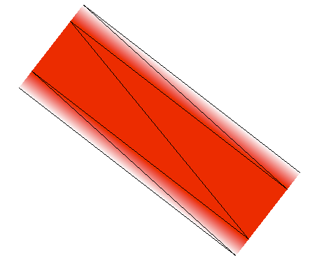
Medium
Maps are mostly made up of lines, as well as the occasional polygon thrown in. Unfortunately, drawing lines is a weak point of OpenGL. The GL_LINES drawing mode is limited: it does not support line…
nice, this sounds like what i need
i've considered the 'shell based' fur shaders too, but i don't think they look right for hairs like this
Hi, I made a shader graph to somewhat simulate filthy clothes. The shader works great inside the graph editor, however when I set a material to use this shader graph and amp up the FilthPercentage value nothing happens, the material is one solid color. What am I missing?
Is your mesh UV'd properly?
looks much better thanks @low lichen
that's just with a quad.. didn't add the extra 2 to the sides (it's too many polys already)
Hey guys, I'm having issues with my triplanar shader setup. I've tried numerous approaches but I think I just don't understand the underlying issues causing my bug. I'm using shader graph for the high def render pipeline to create a lit graph/shader/material. My problem is the following:
Here you can see my normal maps mapped onto a plane and a cube in the albedo input, so you can see what is going on.
This is what happens when I actually use the normal maps as normals. For some reason, there is a darkness at a 90deg angle to the top left of all objects faces
I used the inbuild triplanar node before, but I have already built my own subgraph following this https://www.youtube.com/watch?v=yuiQo54Baos tutorial.

Welcome to 2019! I'm only nearly 3 weeks late.
In this tutorial we're going to build our very own triplanar mapping shader using Unity's Shader Graph. I'm using the HD render pipeline, but lightweight should be all fine and dandy.
We cover the full triplanar experience, and ...
Regardless of which technique I use, I never seem to get it to work
You have to handle normals differently when doing triplanar. The same technique won't work for both color textures and normals textures.
The built-in triplanar node has a dropdown for this, I think
To switch modes
You mean this?
My normals are parsing through a sample texture 2D node set to type normal
The other textures are not*
The triplanar node itself has a Type dropdown too, for Default and Normal
And it doesn't just change how it samples the texture
Then I don't know. I would expect that configuration to work.
Hey guys. I'm having some trouble whenever I add a sprite to this very simple shader, the sample texture "expands" the edge of sprite like this https://i.imgur.com/YLrgY4X.png , this only happens to some sprites, and I cant find a rhyme or reason of why. has anyone ever had this problem before?

packed sprites probably show the atlas textures, and those might have clamp wrap mode
The previews also don't show the alpha/transparency of the texture
Hm. I'll take a look at it thanks, the weird thing is, everything I have is in atlas textures, and 99% of them work fine. they all should have the same settings too. Cyan, the previews dont show the alpha, but any operation I make with that sampletexture2d, takes in consideration all that extra area around the sprite. Its not just the preview that its happening in.
https://i.imgur.com/P0VooBt.png better example, left one with the buggy spritesheet, right one, with one that works fine. Both spritesheets were made in the same program and have all the settings exactly the same.
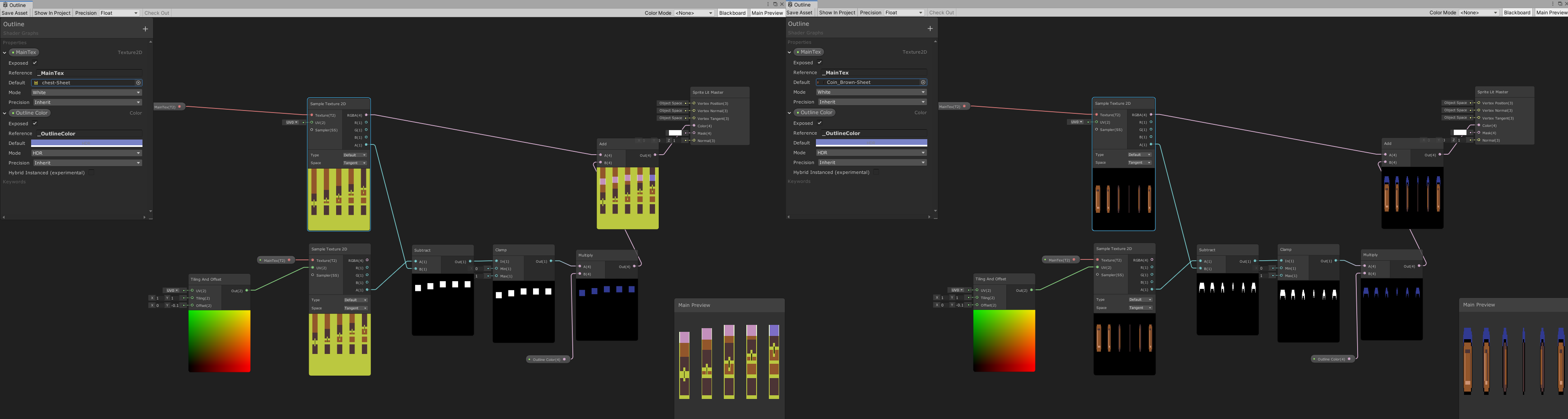
It might be better, if instead of the Add, you used a Lerp with the Clamp result as T, A as Outline colour and B as the sample texture RGBA output. That way the original texture colour won't be added.
mhmm. I made that example real quick to ilustrate the problem tho. That would work for the outline, but it wouldnt really explain why its extending the sprite like that.
actually weird. it does work like that.
still dont get why its extending it like that in the first place tho.
not sure how the preview in the node behaves, are all your texture PoT ? is that happening when applied on a simple quad?
it potentially doesn't matter 🙂
The quad shows "normal" without being extended.
but any operation made with the sample texture takes in consideration the extended area.
The "extended" parts are likely transprent in the normal sprite so aren't seen, but they are probably there.
an actual quad mesh, or a square ui Image component?
Since those extended parts aren't black like in the other image, when you use an Add, the colours are added, hence it's sort of pink rather than blue.
Yeah I get its happening like that, Just checked the original spritesheet tho. What you're saying Cyan is that the "empty" area would be the same color, except with alpha 0 right? its not, its all 000 rgb and 0 alpha.
and Im not sure I understand your question Brice.
(I might be totally misunderstanding the issue 😄 I feel we're not talking about the same thing, Cyan)
"The quad shows "normal" without being extended." > on what ?
on a meshRenderer, on a spriterenderer, or on Image ?
mesh vs sprites vs GUI
Oh. On shadegraph. also in the scene editor and the camera itself.
Litearlly everywhere except that ittle preview.
I'm just talking about the previews in shadergraph. If the quad/UI result looks fine though it's likely not a problem to worry about.
The quad does. but the operations dont. the interpolation you suggested works, but its stil lreally awkward, if I were to add like anything in the area thats being extended, it'd add to that extended color for some reason.
and it wouldnt happen to any other spritesheet I have.
actually its not working the lerp either. im just blind, it's just interpolating between the color and the "extended" weird color, in the clamped area.