#archived-shaders
1 messages · Page 145 of 1
it shouldnt change scale or rotation with what you are doing I think...so I am guessing that matrix is not getting passed in correctly.
@tardy spire Isn't matrix multiplication usually mul(matrix, vertex)? You're putting the matrix as the second parameter here.
instead of using a materialpropertyblock, can you try setting directly on the material the matrix
@low lichen I think that should be auto corrected
@low lichen yea I thought that may be it, but amplify doesn't seem to care and outputs the same result either way
since you cant really do righthand matrix mult
the other thing you can do @tardy spire is grab the 4th column of the matrix and set that as your color. Changing scale should then change the corresponding rgb of the color and you can verify that way
hmmmm 🤔 I recreated the shader in shader graph and it works
neat
theres also a transform node instead of a multiply if you wanted to use it
I believe theres one that takes in a matrix I mean
I can't seem to find it. Also I figured out why it wasn't working in amplify. I needed to convert the vertex position to a float4 👌
Ahhhhhh thatll do it! Nice catch
Can I round a float to 1 decimal in a shader?
just with nodes
maybe multiply by 10, then floor, then divide again?
That's how Math.Round does it
Alright neat, it seems to work
@devout quarry was just about to tweet at you that you should round the vertex positions (in reference to your last tweet)!
pretty sure they need to be rounded in screenspace and then converted back to local to properly mimic retro graphics imprecision
Right now I'm doing screen width/height multiplied by a float 0-1 rounded to 1 decimal
and let's say that float2 is called 'amount'
I do floor((screenspace uvs) * amount) / amount
as my new Uvs
Any matrix savvy peeps around?
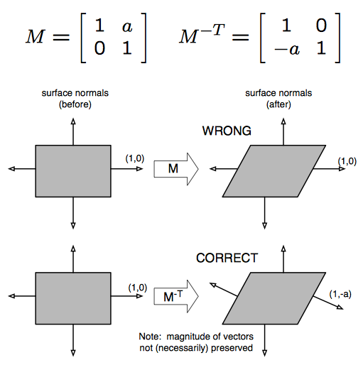
I'm trying to interpolate vertex positions/normals to be relative to another transformation. Vertex positions are easy, but when it came to getting the normal I wasn't sure how to transform a vector as direction with an arbitrary 4x4 matrix. I see there's nodes for transforming between local, world, view etc but those are predefined and I need to transform a direction with a local to world matrix sent via a material property block.
Anyways, I think I stumbled into a solution, but would love to know if this is an ok way to do it!
It appears to work (as long as it isn't scaled negatively), but I literally have no idea why and I'd like to understand if possible
@tardy spire I'm definitely not a matrix savvy peep, but I think directions are supposed to have w as 0 when doing matrix multiplication. Maybe that alone is enough.
Hmm I always thought w was supposed to be 1 🤔
Here's some information about it from someone who knows a lot more about this than me
https://forum.unity.com/threads/mul-function-and-matrices.445266/
Unity Forum
Hi all,
I've been studying shader and there is one questions I could not find answer. Normally we perform the transform of a vertex to clip space by...
(side note) The issue with just multiplying a direction by the local to world matrix is that it will also get translated and scaled (treated as a position)
To transform a direction it should just be rotated. That's why I'm also multiplying a point at (0,0,0) and then subtracting it from the transformed normal. If my understanding is correct, the point at (0,0,0) will get translated by the transformation matrix. By subtracting the result from the normal I'm undoing any translation effect it received by being multiplied by the matrix. Initially this didn't work and I was getting weird lighting so I tried using transposing the matrix first and that seemed to work 🤷♂️
The w being 0 is what prevents it from being translated and just rotated and scaled
But it looks like you have to do more than just that for transforming normals
👀 i think you're right that appears to just work! I had no idea putting a 0 prevented translation and scaling! There's some weird stuff going on when interpolating the normals, but that's a different problem. When it's fully at the start or end it looks fine to me
interestingly when I revert to my old way of transforming the normals it looks exactly the same. I guess I just found a weird roundabout way to get the same result
settings w to 0 is far better tho haha
i am playing with shader graph and i want a transparent material to blend together? like when a river meets the ocean
tell me the deep secrets of how to make that happen? 🤔
this is from the pinned messages, @fervent tinsel did a great simple example of water depth fading https://discordapp.com/channels/489222168727519232/497874081329184799/559409851646607364
this might be close to what you're looking for
oh wow, that's pinned?
I mean there's been way more important topics here but I'm not complaining
haha it's been pinned for a while! back when hippocoder reposted it we were getting like 5 questions a week about water depth fading
Hey. Quick question I'm doing vertex displacement + Fresnel in shader graph. URP setup. The output isn't matching the shadergraph editor in that the fresnel effect doesn't seem to respect the normal input I give it. Anyone who can help me in diagnosing what gives?
Am i missing a setting or something? Am i supposed to do it in a different order?
Here's a super exaggerated version of the wanted result
What happens if you scale the sphere down so it's just (1, 1, 1)? I assume that's the scale of the sphere in the preview.
no i was asking about making two transparent materials blend together
could y'all help a newbie out?
been following one of brackeys's tutorial on how to make a force field. the only difference is i've been making it in HDRP and he was doing it in the LDRP. what i suspect is the problem is the scene depth node not knowing what to do, as i don't see any kind of option for it in the settings
here's how mine turned out compared to his, along with the shader graph in case i missed something
@lone python if you're in HD I believe there is an HD scene depth node that you need to use instead of the scene depth node itself (we are working on making these node usages more clear)
i don't see a node like that when searching for it
there is a HD scene color, but not a HD scene depth
which version are you on?
2019.2.6f1
whats your alpha clip at?
where's that? 😅
on the pbr node
if you expand it you should see a variable called alpha clip
make sure its set to 0
and that the material is set to transparent
the material is set to transparent, as for the alpha clipping, it's set to one
set it to 0
any chance you can upgrade to 19.3? 😅 it should have a lot of those UI bugs solved
and alphaclipthreshold will need to be 0
done, and it works now!
woo!
nice work!
so alphaclip tells the shader "if alpha gets below this threshold, dont draw"
@simple frost Alpha clip is 0 by default, isn't it? It's the AlphaClipThreshold(1) that is confusing, because it's not saying it's set to 1, but that it takes a Vector1, right?
I've had this confusion before
clip threshold is actually 0.5 by default at that version
^
it's been changed in recent versions
Does that mean alpha clip is enabled by default unless you assign 0?
on the PBR master node for HDRP yes, which is why we changed it to 0 in recent packages
so that it isn't enabled by default
Oh, good
okay so in project, the hexagon scrolling texture is still not showing
could it be because of the post processing in the scene?
ah okay, annnnnnnnddddddd where do i find that ^^'
i'm still finding my way around unity
im in a later version of unity atm so check here https://docs.unity3d.com/Manual/ViewModes.html

still not animating?
oh wait, i think i got it
yep. the texture was in the graph, but not in the material
thanks! been at it for 3 hours trying to figure out what the problem was 😆
whenever i try to use a View Direction node, or any node that uses the view direction internally, i get an error and the shader fails to compile (shader graph)
undeclared identifier 'GetWorldSpaceNormalizeViewDir' at line 1285 (on d3d11)
I see an issue posted last year in october and the tracker says it's fixed in an unreleased version of shader graph. seems kinda crazy to think view direction has been unusable for 6 months so I figured there may be an alternative solution
can you link that issue please?
Maybe it's only when used in the vertex stage, which is why it hasn't been noticed by too many?
hmm i also was the person who fixed that.
I'm also getting it in a visual effect shader graph which im assuming is in the fragment stage?
excuse the unecessary view direction node, i was troubleshooting
The color is probably run through the vertex shader and passed to the fragment
But don't listen to me, listen to the devs 😅
what version are you on? 7.2 is absolutely a released package by now (in fact it should be up to 7.3 by now)
actually it might have been just a misversion report -- the bug looks like it landed after 7.2 cut off. it should be in 7.3
hmm I'm on 7.1.8 on 2019.3.7f1 and UPM is saying I'm up to date
It's the verified version, but you should see more if you expand the package
are you using hd or universal?
universal
find universal in PM, use the arrow on the left to expand the version view
you should be able to update to 7.3 that way, but you need make sure you update universal and everything else will go with it
will keep you from getting in a weird mismatch version state
gotcha, thanks! Are the newer versions generally stable? I see they aren't preview packages, but maybe "preview package" is reserved for packages that have never been given a verified release?
It's kinda misleading to show "Up to date" when there is a newer version available and only visible when you click a little arrow that's easy to miss.
yea i wasn't aware until ya'll mentioned it 😆
@stone sandal so after upgrading it works great in a normal fragment or vertex shader, but I still get the error in a vfx graph shader
I can create a bug report if you like
that's probably best, so we can track it
@tardy spire For now, you can calculate it yourself by subtracting the world position of the camera and the world position of the vertex and normalizing that.
does the camera node reflect values of the main camera or current camera? i tried that very briefly but it wasn't working in the scene view so i figured it was pulling values from the main camera. maybe i was doing something else weird tho, because that seems odd to me
Documentation says:
Provides access to various parameters of the Camera currently being used for rendering.
hmm ok, i must have been doing soemthing funky then, thanks 👍
@tardy spire thank you!
where can we report bugs for shadergraph?
position node set to object in sprites flickers a lot, causing incorrect calculations and jitter
it can be easily replicated doing the following
okay!
I created a simple Dissolve shader. When I apply it to two different Raw Images as the material, however, playing with the settings on one affects the settings on another. What am I doing wrong?
@whole salmon That's just how materials work. You have to create two materials using the same shader if you want them to have different properties.
Ok. Can I instance them from a prefab programmatically?
What's best practice for handling a shader that you've built that you want to apply to dozens/hundreds of objects in your game?
I'm assuming you instantiate a shader, attach it to your material, do your thing, then remove it later?
You don't instantiate the shader. The shader is just code. The material has the properties that are passed to the shader, so you instantiate the material and edit its properties.
Unity has a built-in way to easily instance materials by accessing the Renderer.material property.
By accessing that property, Unity will first check if the renderer is currently using an instanced material. If not, it will create a new instance, assign it to the renderer and return it to you.
Wow. Genius.
Renderer.sharedMaterial just returns the material assigned
so if I have my library of materials (just plain materials but each with a custom shader), and attach them using Renderer.material.. i should be good to go?
Is there a way to do that in the editor?
I'm assuming drag and drop onto the Material field gives a shared instance?
Presumably you'd be setting these material properties through script, right?
Yeah
Then just put the original material on the prefab and when you want to modify it through script, get it through the material property and Unity will handle the instancing.
But just to play around with it, it's nice to see it in the editor.. I suppose it's not really a gameplay issue.. just a workflow issue, something to be aware of.. I think I"m going to be combining shaders for various things
OK, awesome. Thanks. Like I said... genius.
You're a mentally stable genius
I have a scene with a bunch of mushrooms as the only source of light, its a cave area. Whats the best way of doing this? I've tried attaching point light to each one but they keep flickering and go through walls and using post-processing doesn't help them light up other surfaces.
@ancient silo How many mushrooms/lights?
And are you using URP or HDRP or just built-in?
URP has a maximum of 8 realtime lights affecting one renderer.
I think the default setting is 4, but can be increased to 8
The bigger the range of the light, the more objects it might affect
Would going over that result in flickering point lights?
This is how they were set up with point lights
If you're going over this limit, it will have to start picking which to prioritize and which to fallback as vertex lights. That could be the flickering, but I'd have to see it.
Is it flickering even when the camera is stationary?
Nope, only when moving. But Point lights also go through surfaces/ walls so I'm trying to find another way of lighting them.
If it's only when moving, then I can believe it's because different lights are getting prioritized which could cause flickering as its switching between lights.
I think it's based on distance from the camera
Maybe you can bake this?
Then you can just use the emission of the material to create light, which will also appear a lot more realistic
Would baking make it so the light doesn't reflect on the character?
It wouldn't without light probes, but if you sprinkle some light probes around the mushrooms, they can light dynamic objects pretty convincingly and fast.
Thanks, I'll try it out
Is there a way to get a shader graph asset to save when I press CTRL+S? the only way I can see to do it is to click "save asset" in the top left of the window, or try to close the shader graph and get prompted by Unity.. neither of which is ideal
does anyone have an issue why in shader code _Variable * value != constant * value?
seems like if I use a uniform constant it looks slightly different form a constant. This is using full float on everything.
this happens when building to a pixel 3 adreno
Hello! I'm basically teaching myself how to program shaders and it's been tough. I have a question, is it possible to permanently write color data to a vertices via a shader?
yes, but probably not via the methods you're thinking of
you're really asking 'can I write to a buffer holding vertex data on the GPU' and while the answer totally is yes, there are specific and generally well thought-out reasons why doing this on the fly is a bad idea
best advice I can give-- the GPU and CPU are fundamentally not the same things and trying to write CPU-ish code for a GPU is a recipe for a bad time
@gleaming moss I can understand that and I want to avoid it if at all possible.
I've been working on trying to do some kind of fog of war that isn't taxing on the system and so far most methods are insane.
I got something going with a shader and I'd like to feed that data back to the CPU to do something so that I don't have to check all verts every frame. If I know what's under the shader, then I'd like to put that data somewhere to be adjusted.
Hey guys, I am new with shaders and am currently developing a way to make a nice outline on intersecting objects. I have made a post about it here: https://answers.unity.com/questions/1710794/problem-with-outling-intersection-using-shader-pro.html As a quick summary what I want to do is find a way to make an outline visible from all axes on a mesh that was clipped. Specifically care about the top view to be rendered properly. Thanks!
Unity is the ultimate game development platform. Use Unity to build high-quality 3D and 2D games, deploy them across mobile, desktop, VR/AR, consoles or the Web, and connect with loyal and enthusiastic players and customers.
Hi I'm having an issue where I made a shader for UI and that after putting it in the game it looks different
If I make a new unity scene and add a canvas/image with the shader on it it works like intended
but as soon as this get placed in my game it becomes really laggy and blurry
does anyone have an idea if this is related to the shader or if my game is affecting the shader in some way
is there any good unity shader tutorial ? 😮
having this issue using URP and the URP/Lit shader set to specular, both of these brown colours are the same hex value, what could be going wrong?
these are the materials
is there any good unity shader tutorial ? 😮
@sharp flint Just shaders in general?
@warm marsh they have a different albedo texture right?
yeah but if the texture is different, they will output a different color
or maybe I'm not understanding what you mean
there are 2 textures one is all "brown" its a light brown orange but yeah and the other one is a blend from that color at the base of the rocks to a grey
so at the connecting point in the pic that is the same color value
what about tiling/offset? Can you make them to line up?
they are 2 seperate game objects, the point at which they touch is lined up in the UVs in term of the color being the same
@devout quarry yeah shader in general 😮
@sharp flint this might help

🔽 Click for Timestamps & Info
This is a several hours long improvised live introductory course to shader coding in Unity! It has been slightly edited in the beginning to remove useless info and me messing around with the mic. The rest is the stream in its fullest!
Timestamp...
pretty long but I think it's useful
@warm marsh If you put each material on a plane and line them up next to each other, how do they look?
The tiling is different on the left one also, but IDK that it will make a diff with that texture. @warm marsh
And the normals are different, so that will impact the lighting calcs
sorry 1 sec ill set up a few screenshots
It also looks like the colours are different on the textures themselves (based on the super tiny thumbs) so it would be good to see the textures next to each other as well
Are they both lit the same way? i.e both dynamic or both static

im stumped haha
I....... yeah
i was thinking its the directional light but even then you would expect some form of transition from light to dark/ color change based on the angle of the light source
Might be worth looking through your quality settings
any particular settings in mind?
no luck with any settings its all mainly in my urp profile
thats with the ground as a cube
and the rock is at the edge of the cube there
@warm marsh Isn't is just the normal of the surface? If you rotate the floor, I'm sure it will cycle through some of the other colors on the rock.
The flat portion on the rock is a similar color to the flat ground
yeah if you look above when i put the samematerial on both objects they had no normal maps and they were still different
Not normal maps
The normal of the surface of the mesh
Which way the surface is pointing
The floor is pointing directly up, the rock is mostly not pointing directly up
The part of the rock I drew a circle around has a similar normal to the floor, directly up, and so it has a similar color.
The lightest parts of the rock are the ones facing the sun
is there no way to get this so they aren't so different?
instead of a normal map on the floor maybe actual mesh deformation?
If you want shading to have less of a color impact, add ambient light
If the sun is the only source of light, then the parts facing away from the sun will be completely pitch black
So the gradient goes from your desired color to pitch black
It's also facing away from the sun, about the same amount as the top part
ah okay got ya
Almost 90° to the right, while the top part is almost 90° up
i didnt know it would be so different, guess ive just never had it so obviously lit and unlit before
The sun is at a very shallow angle, so the floor is going to end up a bit darker
Hi there, I made a HDRP graph for terrains with over 60 exposed properties I wonder if there is a way to convert that thing into a PBR graph, other than copy/paste the nodes into an empty graph. A way that allows me to keep also the exposed property and not recreate them manually (which would take a lot of time). I need to use that shader in a URP project
You just need to change the master node?
What happens when you just drop the file in URP, and open it? Can you open it and change the master node?
Yes ideally it would just be about replacing the master node, but it doesn't seem to be possible
Create new master node, right click it, press 'set active'
then remove old master node
thank you!! I didn't know I could to that
perfect 🥳 problem solved thanks a lot Alexander
My shader starting to act up a bit strange, I have a simple shader that just display a texture, I used Frame Debugger to see what happens and it seems Unity set my _MainTex to the camera render when I click between the Game View and the Scene View any idea what is happening? my texture is set and I never changed it in code
Note again, nothing has changed between the screenshots except clicking between the viewports
That is strange. It's showing a view from a different perspective. Do you recognize it as some camera? Is it the perspective of the scene camera?
And for the record, here is the fragment function
:
float2 uv = i.screenUV.xy / i.screenUV.w;
float attenuation = LIGHT_ATTENUATION(i);
float shad = (1 - attenuation) * _ShadowColor.a;

fixed4 col = tex2D(_MainTex, uv);
col.rgb = lerp(col.rgb, _ShadowColor, shad);

return col;
@low lichen Its even stranger than that! The Scene View show it from a different angle!
its like its based on the unity editor view angle from that specific viewport (game view and scene view)
Are you sure there isn't a second camera somewhere in the scene?
Is this shader writing to depth?
Just as a test, what happens if you rename the _MainTex property to something else?
Wow, indeed it fixed it
Its really weird I don't have any code that touch that shader, to be exact, I dont edit any shader from script
@low lichen Thanks!
_MainTex is used by Unity and is usually set to different values depending on where it is in the renderloop
Hi, I'm starting some tutorials on shaders and I'm having trouble understand "semantics". Are they shader-language specific? Do they affect the shader or are they just for the programmer?
@blissful wraith Have you seen this page?
https://docs.microsoft.com/en-us/windows/win32/direct3dhlsl/dx-graphics-hlsl-semantics
A semantic is a string attached to a shader input or output that conveys information about the intended use of a parameter.
@low lichen ah, thanks. That should clear things up as I learn.

Pummel Party PC Gameplay, walkthrough, review, playthrough, no commentary.
any ideas how the trail / layer reveal is done here?
I've noticed that the 4 different layers are set up beforehand, and the players are just "revealing" their layer
because the greeen guy has flowers in the same spot when he walks over it few times after someone else
which is great because painting with a mesh for 4 players in runtime could be bad for performance
but the still have to reveal the area like a rubber and it has to persist, which I don't know how is done
or is it actually some kind of painting with material?
@vague yacht I would bet you are correct that there is just a reveal going on with the corresponding player layer, but I imagine they are painting to a texture . Could probably paint to a fairly low-rez texture and upsample it for perf.
like, paint to a texture with a transparent brush?
also, the green guys layer looks like a mesh or can you do a 3d shader like this?
I was thinking more paint to a single channel texture and give each player an id mask, like .2, .4, .6, and .8 and have them all draw to that texture with their id and read from that
yeah, as long as those objects use the same or similar shader then it would be fine
read in the texture using worldspaceposition as uv and if my layer isnt there clip
that's not a texture, either
look at the grass meshes
guessing they do alpha clip based on influence
? why could that not be a texture?
sure, so you map 3d worldspace point to 2d plane by clamp and sample uv
rather, I am clarifying that I think there are actually individual meshes being revealed and it's not just painting something into a single shared texture
if that makes sense
since I do agree the actual influence looks like something done with RTT/persistence
Oh yeah no there are definitely meshes being revealed , thats not something a texture could do haha
There's probably one mask texture where RGBA is mapped to each of the players
You know, you can probably hook RenderDoc to it and see how they do it.
Most games work through RenderDoc
If you've used the Frame Debugger before in Unity, it's similar to that but with a lot more information
+1 for renderdoc, love it
honestly prefer the nSight UI
but if it's not available then RenderDoc's not a bad substitute
nor is it a knock on the Unity integration-- just don't really care for how many clicks are required for resource inspection
hah, fair enough!
the Vulkan command buffer situation could do with some improvement if we're talking about Unity usage patterns 😉
that's a lot of nesting
fair jab, well played 🤣
Just wondering, in the shader graph what would the performance impact be of having to use another texture sample 2D node for the same texture? I've got a RGB mask texture but I've made one of the channels use a different scale (tiled 4 times) to give more variation when the base textures are tiled, but to make it work it seams like I'll have to sample the texture again so that I can scale the UVs properly. Is this a bad idea?
It's not a worse idea than sampling a normal + albedo. How many texture samples you can get away with depends on your target hardware.
cost of texture access is all in loading things from GPU memory and that being on the slow end when compared to simple math operations
would likely be the same GPU cost as just reading from a different texture with the same resolution
is there anywhere specific where i can learn unity's shaderlab language?
i'm using 2017 unity (because i'm currently too scared to upgrade at the moment) so that visual shadergraph ui isn't available for me.
long story short, i was trying to apply some simple normal maps to my 2d sprites.
what i have attempted so far was trying to take the old legacy cutout/bumped diffuse shader as an idea. but i've ran into a few issues. so i guess so far i'm trying to learn at the moment is:
since i want to use normal maps, that means i can't use a vert/frag to get the bumped maps to work right? if so, then it's best i use a surface shader?
I am successfully changing the RenderSettings.skybox.SetInt("_SunDisk", 1) between 1 and 2 during runtime. And I can confirm this in the skybox material itself. However, the sun does NOT update accordingly. It stays at whatever mode it was in when runtime started. I am even calling DynamicGI.UpdateEnviroment() after the switch. What else do I need to trigger?
Heyo, pretty new to shaders and I'm guessing everyone here knows what dissolve shaders are, I want to make one that works with just small pixels, for example I have a 8x8 texture that I would like to have a dissolve shader that just changes those pixels instead of smooth dissolving. I'm not sure if anyone here gets what I mean but well, tried my best explaining.
Or some sort of pixelated dissolve shader, maybe 16x16 instead of 8x8 because that may be too pixelated
In shadergraph whenever I use a custom function node, when I move the nodes around in my project, the reference gets lost and the shader doesn't compile :/
is that something that will be fixed?
Is there a way of selecting a single channel for the height input of the Parallax Occlusion Mapping node? It asks for a texture 2D rather then a sample texture 2D so I have to plug in the whole texture, but I'd rather use a packed texture instead
Hum, no
but you can pack by just keeping in mind that it's the red channel that is used
it needs a texture 2D asset input because the parallax node is going to sample it multiple times.
@amber saffron So the POM node just uses the red channel?
double checked in the code : yes
Ah that's great, was already using red for height anyway
Hello peoples 😄 I've started using ShaderGraph recently because it's effing amazing! I've followed a bunch of tutorials and made a bunch of weird things. However, I wondered if there was some really really nitty gritty low-level explanations of how all the nodes work
Every tutorial I've found only scratches the surface. I feel like I don't have the knowledge to write new shaders, but rather copy or modify existing ones from tutorials. I'd really like a solid understanding of how UVs, tangents, world space, the various nodes, etc, all work. Anyone aware of any really good documentation or lengthy tutorials out there? I'm willing to put the time in
these pages often have some info about the implementation of the nodes
This website also covers some nodes pretty in-depth

Like UV, voronoi, fresnel, scene depth, scene color
Does it talk about how they interact with one another? I've actually read up on this before
I'm having more trouble understanding how ports interact - like how a colour becomes a normal, or a direction becomes a colour, etc - sometimes you can pass a V4 into a V1 input, etc
These look great btw
if you plug vector4 into a vector3
the w component will just be ignored
same with v4 into v1
it'll just take the first component
Ahhh, so it goes in order of preference? A V1 into a V4 will just send the red channel?
if you want exact control over which values are used, you should use split/combine nodes
I think if your V1 is for example 0.8
the v4 will become (0.8, 0.8, 0.8, 0.8)
but honestly I'm not super sure haha
That's how it works yes 🙂
what about v2 in v4 then?
Dude, shaders are a total head fuck. Everything's semi-dynamic and doesn't need clearly defining
Would that be (value, value, null, null)?
or (value, value, 0, 0)
I think split and combine are literally the two nodes which solve all my issues haha
definitely
instead of 'combine' node, I prefer to use the vector2/vector3/vector4 nodes
but that's preference
I'll check that out too
Are you familiar with the UV node? I'd like to do something extremely simple, such as scrolling a texture across the Y axis
So I'd like to just plug in a time node to the Y value
But the UV node has no inputs, so what exactly is its purpose?
tiling and offset
check the tile/offset node for that
put that into the uv
multiply time with speed variable, and put it in the y slot of a vector2 node, then that goes into the offset slot of the tiling and offset node
+1
Thank you 😄 I'll have a look at that too
I feel like half the time I make a cool shader, it's totally accidental

Been messing with lit 2D sprites at the moment to create this disgusting looking fellow
Hey guys, I had written a post above but will try again. Maybe the issue is very difficult to fix but could anyone please guide me in a correct way for a nice solution? https://answers.unity.com/questions/1710794/problem-with-outling-intersection-using-shader-pro.html As a quick summary what I want to do is find a way to make an outline visible from all axes on a mesh that was clipped. Specifically care about the top view to be rendered properly. Thanks
Unity is the ultimate game development platform. Use Unity to build high-quality 3D and 2D games, deploy them across mobile, desktop, VR/AR, consoles or the Web, and connect with loyal and enthusiastic players and customers.
I think that what you're asking for might not be possible to do without more complex methods, IE : rendering in a separate buffer the objects you "cut" to do a per pixel outline, and compose with the main rendering afterwards
@amber saffron Sounds very interesting, do you perhaps know a tutorial I could watch about this? I have never used a seperate buffer to render stuff
@amber saffron My colluegue reccomended to read about "Compute shaders" do you think that might help come closer to the solution?
I'm not sure compute shaders will be any help here...
This type of thing might be a base for what you're looking for : https://forum.unity.com/threads/screen-space-outline-effect-for-unity-free.836908/

Unity Forum
Hello Everyone!
I'd like to present free open source outline effect package:
Github repository;
Npm package;
Documentation.
UnityFx.Outline...
I think that what you're asking for might not be possible to do without more complex methods, IE : rendering in a separate buffer the objects you "cut" to do a per pixel outline, and compose with the main rendering afterwards
@amber saffron Might this be about Command Buffers?
Well, it can be done without command buffers, but yes, it's a bit more optimal 🙂
@amber saffron I wanted to ask, do you perhaps know WHY the intersection shader vertex positions cannot be changed. Like what happens is, when the bounding box is inside an object, it colours all intersecting faces. Why cannot I just move the point I would like to colour? I was thinking to modify the intersection points and change their normals such that the outline is actually seen from above.
Hi there ! I'm looking for help about ShaderGraph. I need to make a porting of a surface shader that relies on a compute buffer, but compute buffers seem not to be supported in ShaderGraph
I'm not sure to understand what you're saying here @somber quest
is there anyway to write a compute buffer on a material in HDRP and read it in ShaderGraph
@amber saffron to shortly explain, the intersection shader has 2 passes. In the second vertex function we just o.vertex = UnityObjectToClipPos(v.vertex); and in the frag just return _Color;
What I wanted to do is edit either o or v in the vertex shader. Like offset it or change the normals. I could not visually see a difference though. I am not sure why
Editing o.vertex should deform the shape
@lavish ermine not at the moment iirc
Maybe through a HLSL include file used in a custom function node :/
@amber saffron this is something I need to try, but it seems that setting a buffer on a meterial is not allowed in HDRP
do you know if this is a planned feature?
Don't remember on top of my head, sorry.
I think it is something that is quite often asked tough
Thank you. I will try and dig more on the subject
I don't think that's a 100% trivial question
pixel shaders can write to unordered access views since the beginning of D3D11 but there are some constraints-- other stages did get the ability in later revisions/11.1-ish but that might change based on 3D API
figuring out where that buffer export gets run sounds like a complex question too 😐
sounds like another great application for custom master nodes
@gleaming moss Again, a custom master node would require an access to a GPU buffer in a way or another. In my case (HairStudio, a hair simulation), the vast majority of the data used to shape the geometry is located in the buffer, not in the mesh. This data is produced by a compute shader, and if I need to read it back in CPU memory to update the mesh, I encounter a big performance hit
@gleaming moss no, I don't know that function and I don't quie understand it. How do you use it inside ShaderGraph?
it's an app/C#-side function, just related to binding the resource(s) you're working with
at least for write
looks like the global buffer set functions can deal with read-only binding too-- was afraid it only handled constant buffers, but it looks like you can supply read-only views
I understand the how it can help in binding GPU data in some situation, but I can't figure out how to access a buffer via the ShaderGraph. I still need to try and set a buffer (and other data) in a material in HDRP and see if I can access it via a custom node HSLS function
and as Remy mentioned, you need an HLSL file that declares a buffer resource and reads from it given an element index
I know how to delcare a HLSL function in a custom node, but I can't declare a buffer in a function. I would need that buffer to be declared in a custom input.
you can't, they're always in the top-level scope. You can include a file that declares the buffer and the function
how that?
and then just reference the function in the custom node
Create your include file and select it in the custom node
so if I declare a custom node that is using a HLSL file, I can declare new shader variable in the HLSL code?
exactly

Service to share files/parts of a file with others.
something like that is possible?
already got it 🙂
so you would want an output for each member of the struct
and probably a uint or something with the index of the buffer
remember that I only need to read the buffer, not write it
so I just need to give an index in the method parameter, and the result are two float3 in my case
I need to try that ^^
and that might be more complicated
why would it be more complicated?
writing from the regular shader pipeline-- talking about two different things
sorry, fast topic change
ok
well, I will write inside this shader from a compute shader. maybe I will issue some difficulties in predicting the order of execution
compute shader will write sometime, and the shader will read each time it renders.
I'll give it a try and see
well, thanks you, it have been very informative ^^
In a compute shader, is it better to send less bytes of data but remap the values into a different float size in the shader itself, or to just send more bytes of data but not have to remap the values in the compute shader?
Example:
- Vector3 position which is 12 bytes is sent to the compute shader, but the z is always 0
- compute shader takes it in as a float3, then does math, ending up with a value for z (so it NEEDS to be a float3 in the compute shader)
vs - Vector2 position, 8 bytes, is sent into the compute shader
- compute shader maps it into a float3 (
float3(position.x, position.y, 0)) then does math
first version is correct
in the second solution, you would have a map with x,y as input + a map with x,y,z as output. even if the map is full of 0, it is allocated in memory and sent
@lavish ermine sorry position was a bad wording, offset would be better. It would be sent in as a vector2, taken in as a float2, then lets say adding to a position:
position += float3(offset.x, offset.y);
position would be a seperate vector3/float3, these are seperate sets of data
If you need the data to be separated in gpu side then yes, you need two array. But if the first version of the data can be lost after the function, one array of xyz should be better. Note that you will certainly notice little to no difference if it's only memory transfer CPU->GPU
Hello, so ive been told that sending data to a shader is faster than using SetPixels() on a Texture2D. is this true?
I don't really know anything about shaders so
copying data from the CPU to the GPU is going to be about the same speed in both cases. Updating a few pixels in a texture is probably going to cause the whole image to be uploaded again, though
this isn't a complete question
is it all the same data? How often are you doing it?
what are you really trying to do
@sonic plinth same anwser. updating the data of a buffer or a texture will lead to the same time if they haze the same size, I think
and it will be hard to test the difference between the two
@gleaming moss I have tested placing a uniform variale in my custom node HLSL file, but it doesn't seem to work. The data does not seem to be written when I call the material.setFloat(myFloatID, value). I also get an exception "Material doesn't have a float or range property 'MyFloat'" when I try a material.getFloat(myFloatID)
Though I've found that uniform variable are allowed in such situations in the ShaderGraph node here : https://docs.unity3d.com/Packages/com.unity.shadergraph@6.9/manual/Custom-Function-Node.html
@lavish ermine I suspect you need to use the global Shader.SetFloat()-- Unity properties have a whole infrastructure outside of shader code itself
Has anyone tried making a dissolve shader that works on 8x8 sprites and only changes the pixels on that. or 16x16 because 8x8 might be too small for dissolving. Hope someone here understood what I said
there wouldn't really be anything special about it, it already works on one pixel at a time
maybe disable texture filtering if you don't want that
@gleaming moss Thanks you for your time, it's very kind. I've found a static method called Shader.SetGlobalFloat(...). Are you talking about that? It seems to set the value for all shaders, and seems dangerous. Plus in my case, there are many instances that requires their own data set.
@gleaming moss I'm confused on what you mean
@sonic plinth regular dissolve shader should do what you want if it's a 8x8, 16x16 or 4096x4096 texture/render target
shouldn't need to modify anything
if you're doing pixel art stuff then you might want to turn off some of the blending the card does to textures
Huh, when I try to make one the dissolving is high resolution compared to the sprite size
how are you determining what area(s) to make invisible
well, dont really have any anymore, deleted my dissolving script so I will have to make a new one
plus, dont really know a good way to make a dissolve shader in the first place. Quite new to working with shaders
are you using shader graph or writing it by hand
shader graph. writing by hand seems harder
ok, and is this for a lit object or are you still working with tiles
its a gameobject, not apart of my project's texture world map if thats what youre talking about.
that's fine, just figuring out what master node you need to work with
the big change is making sure you have the 'alpha clip' turned on in the master node options
Yeah, using LWRP if that is necessary information :p
dissolve stuff is really just alpha testing like you might see in a static, painted texture
if you have a noisy input and gradually increase/decrease the opacity values, you end up with this grainy effect that looks like the surface is crumbling into ash
I'm a little confused on how to actually make the dissolve shader, as ive never really used shader graph before
instead of writing code, you drop nodes in and connect them together
it can help a bit to see visual representation of a few steps as you're making things
Yeah I get that but unsure how to make a dissolve shader with it, since I don't know all of the nodes and how they work yknow?
the big change is making sure you have the 'alpha clip' turned on in the master node options
dissolve stuff is really just alpha testing like you might see in a static, painted texture
if you have a noisy input and gradually increase/decrease the opacity values, you end up with this grainy effect that looks like the surface is crumbling into ash
there are also a few video examples of how to put them together on YouTube-- some of this will change depending on how you want to control what dissolves when
a bit of a dumb question but how do you remove a connection
actually nevermind
@gleaming moss alright so, you can see here that the resolution of the dissolving is way higher than the sprite itself, which is not what I want https://gyazo.com/12d1efd84499b6e8aa1cd4454030fc09

ok, was that made with your graph?
if so, post a picture and let's talk about how it works
here. (the border of my sprite is like the same color as the background color so you cant really see it)
one of the first things you can try is adjusting the scale of the noise node on the left
well, no matter what scale it is the noise is always gonna be high resolution
are you interested in working at the scale of pixels in the source image?
as in whole pixels going away at once
Pretty much, but probably at maybe 16x16 instead of 8x8
you have a few options then
you can chunk up the input UV that you feed in to the noise node
that would be done by reading the sprite texture coordinates (there's a node for this) and then feeding it into a 'posterize' node
alternately you can create a noise texture that's 16x16 in your favorite image program and make sure it uses point/no filtering
which is an option when you're importing the texture
you could then replace the noise node with another texture read
well, what is the "sprite texture coordinates node" called?
should just be called UV I think
this seems to work well, though the colors are pretty much gone
figured that out, multiply the value after step with the RGBA from sprite
one thing to keep in mind is that the "resolution" won't be affected by object scale (and if you don't use/need this, then no sweat)
it might make sense to have the 'steps' parameter come from a property too
Yeah I know
so you can increase or decrease the virtual resolution according to scale
I just disconnected the dissolve amount so I can test in the editor faster
also; it seems the sprite becomes semi transparent in the end for some reason
and some pink somehow got into the sprite, probably from the multiplying
try flipping the 'edge' and 'in' inputs in the 'step' node
those look backwards
'edge' should be the dissolve amount
second, try multiplying the alpha and noise and putting that in the 'in' input
then combine the regular sprite color with the alpha
@gleaming moss You were right, myMaterial.setBuffer(myPropertyID, myBuffer) works like a charm. So it is indeed totally possible (and pretty strait forward) to set a buffer on a material using shaderGraph.
still collecting reasons to yell at Unity Engineering for custom master nodes tho 🙂
Anyone know of examples of custom unlit 2d shaders which hook into the lighting system?
(in shader graph)
3D ones would probably work just off the top of my head
I don't think the 2D nodes need different shader constants
That was my initial thought, and I adapted some 3d custom functions, but my sprites aren't lit
Just wanted to see if there was anything I could reference more specifically as I continue investigating
nope, join me in yelling at Unity for custom master node then
non-photoreal rendering is kind of a bad joke with Shader Graph rn
@gleaming moss not sure what you meant with "combine the regular sprite color with the alpha". currently looks like this
@sonic plinth yeah, that didn't work out as well as I want-- you do need to multiply after the step
since the basic sprite alpha should work independent of the dissolve threshold
that's my b
so what, just remove the multiple between noise and step?
works good except for some areas https://gyazo.com/ee162a8057c018eada01a11d38f8be33

you can see just a little row of colors at some areas
yeah I see that little line
wonder if that's a precision problem with the Posterize node
can I ask-- did you check the import settings for your texture?
if possible, try turning off mipmaps and setting it to point/no filtering
afaik the only difference between 2d and 3d shaders is that you need to get your colors/normals from _MainTex and _NormalMap. Anything I'm missing there?
(also, new to Discord - does it have threading? I feel like I'm interrupting)
it has no mip maps and is point/no filtering
@cloud turret no, Discord is glorified Slack is glorified IRC
Slack has threading :/
also; I would like if the pixels didnt just disappear completely and instead fade like usual dissolve effects, not sure if this is possible with how it currently works but yeah
@sonic plinth you can make that happen, but you need to change/remove the Step node
Huh, though well, not sure if I can do it myself :p
(just make it 'subtract')
oh that was easy enough
some weird things are happening with that though
I mean, it doesnt really work with a 0-1 input
how so
it becomes completely invisible at like 0.6 and visible at like -1
maybe flip operands?
the time node is to visualize animation
yeah, that does take some more work to get controllable
what do you mean operands?
inputs to the node
you can also scale and bias the dissolve factor to compensate
probably the easiest solution
use the Tiling and Offset node with values of 0.5 on the shader
it seems having the noise go to B instead of A makes it so 0 is invisible and 2 is completely visible
yeah would suggest setting it like I have in the picture
just didn't see how you arranged the subtract
exactly how i wanted it to look! https://gyazo.com/a362f6009d28fc7b3498f2f966ec4a24

Anyone know for sure if methods like GetMainLight work in 2d?
Haven't been able to track down any 2d render pipeline specific shader code in github
hey so is it possible to have a 'transition' between these 'tiles' with a shader? the whole map is a big Texture2D so it should be able to be done
Anyone?
Trying to translate a graph from amplify to unity format. Need help with a few missing nodes. What would be the equivalent of Register local variable ?https://inresin.wordpress.com/2020/04/03/terrain-and-mesh-blending-in-unity/
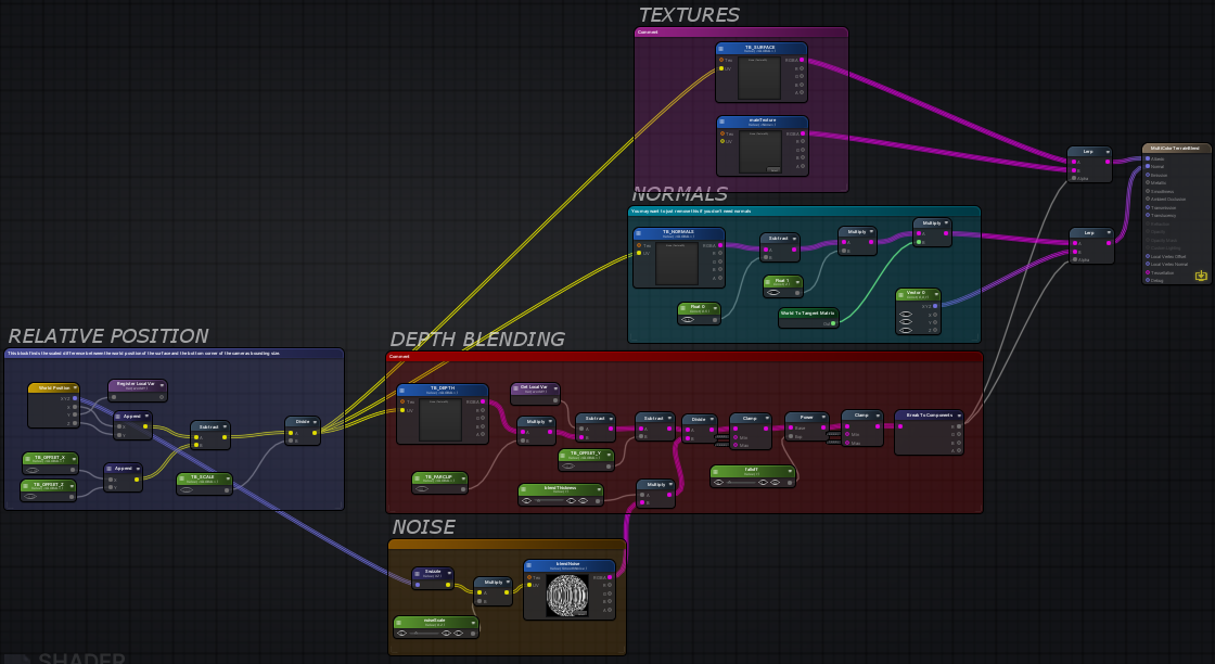
In this tutorial I’m going to go over how to blend meshes with terrain (or even other meshes) in unity. This tutorial is fairly advanced, but I’ve tried to break it up into individual stages. I ass…
@proven sundial I don't think there is an equivalent. It's stores the value in a variable which can be obtained via the Get Local Var node later on. The purpose is just to make the graph less messy. In shadergraph, you'd just have to drag the output directly into the other slot.
Ah, ok!
Messy graphs is my speciality, so that shouldn't be a problem! 😛
And for Append, I'll use Add, right @regal stag
No, I think the append is putting the two Vector1 values into a Vector2. The equivalent would be the Vector2 or Combine node
Thanks, last question for now:
R=X
G=Y
B=Z
?
Yeah, and A=W for the fourth component.
I suspect you've gone over the tut/breakdown yourself already?
I read through it briefly but haven't tried it out
I find it a bit odd that I have to render a heightmap, shaders that give similar results, that I've come across in the past (looking at @desert pumice ) didn't seem to need that.
re-rendering the terrain ever frame seems an expensive way to do mesh blending.. terrain is static. That said, it does handle some dynamic cases nicely..
I got a question
So a directional light has a vector3 rotation right
the values in the inspector
How can I convert those values to a direction vector?
I don't want to read the rotation in the shader or anything, I can input the rotation values manually
but I want it converted to a direction
I mean I can convert it in my head, for example a rotation of (45,0,0)
would become a direction of (0,-0.5,0.5)
Hi! There is any recommended shader to try to make a decal?
@devout quarry Why do you want to do this conversion in the shader if you're inputting it from script?
@grand jolt It depends on what rendering path you are using, forward or deferred
I'm not inputting from a script
I want the direction hardcoded in there for now
but the direction needs to match a certain rotation in eulerangles
@low lichen How can I know it? Im using the URP
@devout quarry So you just want some method of converting euler angles into a normalized direction that you can do in your head?
@grand jolt URP is forward rendering
or calculator
but yeah basically I want to know how I can convert euler angles to normalized direction
but maybe that's not really shader related
@devout quarry I'd recommend installing the Immediate Window package in Unity so you can just input:
Quaternion.Euler(whateverX, whateverY, whateverZ) * Vector3.forward
And it will print out the direction you want
Or do it in a script
@low lichen And that supports decals? Or do I need to fake it
@grand jolt Decals are easier to do in deferred, because it has all the information you need about the scene ready to use. That is the depth buffer and the normal buffer.
@grand jolt You can still do decals similarly to how they are done in deferred, but you either have to render the normals texture yourself or calculate the normal by sampling the depth texture multiple times and calculating a normal.
@low lichen Ill try to look about it then, thx
hi guys, so i'm making a shader in shader graph
i am using rotate on a sample texture 2d to rotate the texture 90 degrees, and i want to add a tiling and offset node to make it scroll, and i tried things like multiplying/adding rotation to the tiling and offset, and also trying to put the sample texture into another one somehow but that didnt work either, how can i do this?
have you tried connecting the output of the tiling and offset note into the rotation or vice versa
no, but i fixed it anyways, it was a super simple texture so i manually rotated it and made a new texture with the rotation
but
i do have one more question
its simple
so
is there any way
that I can do something like the hdr effect
where it is kind of a low intensity to a high intensity
but with a gradient
e.g the high intensity is a different color
Can anyone guide with normals recalculation? I'm displacing vertices with my vert shader, how could I recalculate the vertex normals based on that displacement?
@gleaming moss Hey hope I'm not being annoying by asking but how would I turn the 0-2 range to a 0-255 range?
@sonic plinth mostly adjusting the parameters to the tiling and offset node in the graph
I dont have a tiling and offset node, where would I put one
are you tweaking the dissolve amount parameter before putting it in the subtract node
I'm not no
well I want the dissolve amount to be 0-255, instead of 0-2
are you talking in general or is there something I don't remember
what does the graph look like right now
the dissolve amount range currently works like 0-2 but I want it to work like 0-255
setting it to 255 makes it like semi transparent
you did mean like dissolveamount/255?
and the dissolveamount range being 0 - 255
right, so the final formula would be like (2 * dissolveamount / 255)
which can be simplified to (dissolveamount / 1) * (2/255)
cancel the division by 1, get (dissolveamount * 2/255)
quick sanity check, if dissolveamount is 255 then it becomes (255 * 2 / 255) or just 2
or 2 * 255/255
I just did dissolveamount * 2 and divide that by 255
@gleaming moss how would I add a random offset to the noise so it doesnt look repetitive every time a item dissolves?
anyone know why this stretching happens in the image on the left? it doesnt happen in any videos ive seen
is that maybe what the image looks like without any alpha value?
That's how it looks without alpha visible
So it's an issue with the way the png was saved?
no you often want to repeat pixels like that so that if the alpha samples a little wider the colors maintain the same
if you say filled that area with black pixels the final image when mip-mapped down might end up writing a bunch of black pixels
so it would have the sprite have a weird outline
im adding an outline, and those stretched pixels are affecting the output, tinting the outline
I'm not familiar enough with the sprite shader graph to understand specifics I'm afraid, what does your outline effect look like?
as in how is it implemented
ah, the reason i wasnt seeing it in videos is that they have a solid color outline on their sprites
im shifting the alpha in 4 directions, then adding them together and subtracting the original alpha to get a border. then coloring it and adding it to the original
the white center of that ship is lightening the border
so there are a couple of ways you can fix it, you can first multiply the RGB of the base texture by the alpha then apply the outline, that is probably the cheapest
otherwise you are gonna want blends, lerps or branches
multiplying the alpha worked perfectly 🙂
don't know how well SG optimizes but if it collapses down correctly it should just be a single MAD so same cost as what you had before
now im left with a black background on it 😂
i should be able to manage this
got it. thanks for the assist!
no problem, glad to help
it doesnt seem to work properly on a sliced sprite. it seems the other spites in my sprite sheet are getting borders that extend onto nearby sprites
hmm I don't know how the sprite sheets work, but you might try setting it so that the sampler state is set to clamp
didnt seem to change anything. the sheet itself is set to clamp.
i may just need to split the sprites so the shader samples individual textures
seems like there must be a way to do this, though
like I said I'm not too familiar with sprites, how are you selecting the different sprites?
its set on the SpriteRenderer component in Inspector
so you aren't doing it in your shader at all?
can you show me what a UV node looks like ?
ok, so you might be able to use the UV's to mask things
so you might be able to just throw a saturate in between the UV node and the sample texture node
doesnt seem to have changed the final output
The blue at the top to the left and right are from the ship sprite above
how are you expanding your alpha?
I'm offsetting the alpha in 4 directions, then adding those together
Hi guys, I am working on a2D project in which water shader is rising and if it touches character, the character dies.. I have very limited knowledge about shaders and have no idea how to implement collision detection. Please help..
@cursive jewel Shaders are usually not a great means of driving gameplay things, you likely want to have some sort of game object separate from the shader for that and then have the shader match that object
a box collider would probably suffice
@twin swallow so the problem is you need to mask out any pixels outside of the base 0-1 UV space
this should give you a mask, but you will have to offset it along with your outline
@lime viper @twin swallow Thanks
Not sure if im doing something wrong. This is a bit over my head 😅
ive managed to make it output nothing
heh, to be fair my technique might be flawed for sprite based stuff
I think the added complexity is making the sprite atlas not worth it
I mean it maybe that Unity just hasn't implemented the feature you need for it, 2D shader graph is pretty new
do anyone know how to compile shader at runtime
Anyone knows how could I get distance from the forward-facing side of mesh to the back-facing one through graph editor?
I need that to know "thickness" of specific point.
I have glowing polygonal trail, that shrinks over time. If it becomes too thin, aliasing gets horrible. I want to prevent that by making it more transparent, depending on it's width, so to say.
Please help.
Is there a way to debug compute shaders via RenderDoc with debugging info? Currently it displays disassembler code...
I read about #pragma enable_d3d11_debug_symbols but it is used in standard shaders, not Compute Shaders...
Hmmm.
Vendors have their own tools, and PIX captures frames and lets you edit/debug shaders in simulation. BUT...IDK how/if it works for compute shaders.
PIX last I knew needed DX12
My game is DX11 and PIX does not support it, at least 2 latest versions
But you're debugging!
Can your dev pc support DX12?
switch to DX12 for debugging. Switch back when done.
???? Maybe ????
i'll try
Good luck, but I'd check for compute shader debug support first. like I said, IDK about that.
@fickle crypt latest PIX has DX11 emulation for DX12
I tried, it exits with Exception
hmmm I wonder if it's published yet
did they state it supported that already?
they did mention it on DirectX stream few weeks ago I think
hello, i'm using a compute shader for some calculations and retrieving the data back to the CPU. I require to reset the buffer each time i dispatch the shader, however, setting a new buffer via shader.SetBuffer() is not working to refresh the data back to 0 if i Dispose()/Release(). If i don't Dispose()/Release() of the previous buffer, it works, the data gets nicely gotten rid of and then when i set the new buffer, all of it's values are 0. However, then i'm spammed with warnings that the GC has disposed of the compute buffer and that i should use Dispose()/Release() to get rid of the data properly. Is there a way to reset the buffer that i'm missing?
I usually have a dedicated kernel for clearing the buffer
i see, so you dispatch before the main dispatch to clear the data?
Yeah
@low lichen thanks
Guys I would like to ask, would it be possible to have something like box layer which can make the graphics at the back affected by the boxed-shader
Let me draw first
hi guys, just had a quick question. Im new to shader graph, and essentially I have a bunch of scrolling textures which I used add nodes to combine them all. Is there any way to input that final add node into a another tiling and offset node to offset the texture and then add the final add node and tiling and offset to create a duplicate
And now you want what exactly? Or what is not working?
its a bunch of textures, and what i wanted was essentially those textures (scrolling), but offset. Essentially taking the final add node with the combined texture and duplicating it with an offset.
I thought maybe I could take the final texture and put it in another add node, and also have the final texture input into tiling and offset, and the tiling and offset into the add node
Yes that sounds possible, thats what I meant, did you try it and if yes, what is not working?
@fickle crypt IDK if you're using VS, but check this out:
https://docs.microsoft.com/en-us/visualstudio/debugger/graphics/walkthrough-using-graphics-diagnostics-to-debug-a-compute-shader?view=vs-2019&redirectedfrom=MSDN
Im trying to create a simple reflection glass shader graph. Right now it is reliant on a reflection probe, but this has some issues:
As you can see, because the glass is part of one material, they share the probe, which is problematic. I'd prefer to not make all of the windows different materials.
So, in URP, is there a better way to get reflections?
use HDRP, only partially ironically
reflection probe volumes solve this for you
you might be able to wrangle the deferred shading mode in URP into what you need, but that's not actually out
is there a shader that can make clothes look dirty when on? like smeared colors over the textures
You can craft that with a material blend shader
or really even just a grunge overlayed could do what youre looking for
or duplicate your geometry and apply a tileable of that grunge over it as a decal but then thats +1 geo so might want to pass by a material
@leaden gyro reflections with probe in URP are not for things like mirrors / water. They give a general projection. Which is great for rough surfaces, but where you want a mirror like reflection you will need Planar reflections. I suggest looking at the "boat attack" demo from Unity. It has a planar reflections script which you can attach to a camera and then use the provided texture as input in shadergraph.
Ill have a look at how accessable that is @thick fulcrum , thanks
is it possible to create a frosted glass material in URP?
@warm marsh yes it is possible, you will need to enable the opaque texture option in the URP settings. Then you can access it in shadergraph, also need to make sure your in transparent mode for your shader. Then you can affect the texture to give you desired results. If you google there is an example in the forums done by a Unity guy some time back.
@thick fulcrum thanks bud, I just cracked it, appreciate the help though
how can i access unity_OrthoParams in the shader graph? (it's a global variable (vector 4) that is already defined)
@mystic kiln The Camera node has outputs of unity_OrthoParams values.
float _Camera_Width = unity_OrthoParams.x;
float _Camera_Height = unity_OrthoParams.y;```oh, thanks
@slow turret Don't cross-post. pick one channel.
If i'd knew which one it belongs to
hello, i have a problem with using textures on Materials. I'm using a RenderTexture as a heightmap in one of my shaders and i am updating this texture each FixedUpdate with Graphics.CopyTexture(). When i do so, materials which use this texture do not get updated and i need to update them manually by assigning the same texture that they're supposed to be using again. Is this expected behaviour?
does anybody know where the URP equivalent directory is located Packages/com.unity.postprocessing/PostProcessing/Shaders/StdLib.hlsl
probably something like
com.unity.render-pipelines.core/ShaderLibrary/Common.hlsl
I don't think there is a one-to-one equivalent? Which functions do you need?
Hi guys, i wanted to ask if its possible to add a galaxy parallax effect onto a 2dsprite and when it moves u get the galaxy effect? like d3 cosmic wings or fortnite skins samsung, or poe shaper realm
hello, i have a problem with using textures on Materials. I'm using a RenderTexture as a heightmap in one of my shaders and i am updating this texture each FixedUpdate with Graphics.CopyTexture(). When i do so, materials which use this texture do not get updated and i need to update them manually by assigning the same texture that they're supposed to be using again. Is this expected behaviour?
@naive mural
What do you mean by "materials do not get updated"? Graphics.CopyTexture() happens on the GPU not the CPU. Do you mean to say that the copy didn't work on the GPU?
@meager pelican I fixed my problem. The texture was getting updated, however, the materials which i presumed to be using the texture were not to the effect that the texture has changed. I forgot that i was creating the texture at the start, however, was not assigning it to the material with the new texture. It was still using the old one, which is why i thought while updating the texture the material was for some reason keeping a copy of the previous texture before the copy and holding that as the reference. I was just using using 2 textures in total and forgot about it.
can someone help me add alpha cutout to the standard asset toon shader
ive been trying and im lost
this is what i have so far
    Properties {
        _Color ("Main Color", Color) = (0.5,0.5,0.5,1)
        _MainTex ("Base (RGB)", 2D) = "white" {}
        _Ramp ("Toon Ramp (RGB)", 2D) = "gray" {}
        _Cutoff ("Alpha Cutoff", Range(0,1)) = 0.5
        _Mask ("Mask", 2D) = "white" {}

    }

    SubShader {
        Tags { "RenderType"="Opaque" }
        LOD 200

CGPROGRAM
#pragma surface surf ToonRamp

sampler2D _Ramp;


// custom lighting function that uses a texture ramp based
// on angle between light direction and normal
#pragma lighting ToonRamp exclude_path:prepass alphatest:_Cutoff
inline half4 LightingToonRamp (SurfaceOutput s, half3 lightDir, half atten)
{
    #ifndef USING_DIRECTIONAL_LIGHT
    lightDir = normalize(lightDir);
    #endif

    half d = dot (s.Normal, lightDir)*0.5 + 0.5;
    half3 ramp = tex2D (_Ramp, float2(d,d)).rgb;

    half4 c;

    c.rgb = s.Albedo * _LightColor0.rgb * ramp * (atten * 2);
    c.a = 0;
    return c;
}


sampler2D _MainTex;
float4 _Color;
sampler2D _Mask;

struct Input {
    float2 uv_MainTex : TEXCOORD0;
};

void surf (Input IN, inout SurfaceOutput o) {
    half4 c = tex2D(_MainTex, IN.uv_MainTex) * _Color;
    o.Alpha = tex2D (_Mask, IN.uv_MainTex).a;
    o.Albedo = c.rgb;
//    o.Alpha = c.a;
}
ENDCG

    }

    Fallback "Diffuse"
}
i still dont have a cutout effect
@median lava Have you looked at other alpha cutoff shaders to see how they do it?
There's usually a clip() or discard; involved
ive seen the discard before but i dont know where to put it
It's a way of discarding pixels. So you'd do it in the surf function, which is run for each pixel
And you'd probably want to only do discard; if the alpha is lower than some cutoff
You don't have any variable named color in your shader
_color
And the surf function is void, it doesn't return anything.
return color;
The method doesn't return anything, why are you trying to return something?
You'll just get a compile error
And I assume you mean _Color, but that property is always the same, regardless of the pixel. It's just the color property in your material
So if you do the alpha clip based on that, the whole object will disappear if you reduce the alpha of that color property below the threshold
You probably want to take the texture alpha into account somehow
ok ima try that
I have this pattern
But when I zoom out these patterns emerge
Does anybody know why that his?
I see these patterns sometimes in other things to, when things are small, packed together

You solve it with mip mapping
nope
I'm not using any texture here
you hide it with mipmapping
That's an interesting link, thanks
It's a problem, mip mapping is a solution
it's innate to any sampling, you can just attenuate high frequencies with mipmaps first as a prefilter
it's somewhat possible to counteract mathematically if you know extra information about any high-frequency signals in your shader
basically anything likely to change a lot over the span of a few pixels onscreen
triangles are actually one of the mostest classicest examples
infinite-resolution source signal (basically limits of floating-point resolution) mapped to considerably lower-resolution screen
Wait until you use some anti-aliasing (or even not) and you get the creepy crawlies. That's fun too.
I'm setting some shader properties via a material property block and it's working great, but the property I'm setting is **not **marked with the [PerRendererData] attribute in the shader. What is the point of the attribute if it works without it? Does it improve performance?
@tardy spire I believe you end up writing more constant data for every draw call
@tardy spire Nope. As I understand it, it used to be necessary, but now it just hides the property
Interesting, maybe I should test it 🤔
On a similar note, do you know if there's a performance benefit to create on material property block and send it to multiple renderers, or create a new material property block for each renderer. Ignoring the increased memory and time spent setting the same value on multiple MPBs, I'm curious if there's a rendering cost. I guess this is another thing I can test, but if someone already knows it'll save me 10 minutes 😆
When you call SetPropertyBlock, it appears it just copies the data from it, because if you modify it, you still have to set it again.
there's always going to be some decoupling with constant data since there's an actual write to GPU memory involved
Ah right. Makes sense! Thanks @gleaming moss @low lichen
yeah tl;dr I don't think there's a 1:1 relationship with cbuffers to MaterialPropertyBlocks
Ignoring the increased memory and time spent setting the same value on multiple MPBs, I'm curious if there's a rendering cost. @tardy spire
Well, if you ignore all the extra cost stuff, then no. 😉
Don't forget to ignore the extra cost of uploading the extra redundant data to the GPU too.
Seriously, though, the various "batchers" handle all that, that's all part of the batching restrictions for those cbuffers, as I understand it.
But if a different renderer used a different buffer somehow, then I suppose it doesn't result in duplicate reads from the buffer. So it would be handling overhead, as I understand it. ?Or there's only ever one buffer?
So IDK if it's possible to force different CBUFFERS for the same shader/material using MPB's. at all.
i got an error message variable 'c' used without having been completely initialized at line 32 (on d3d11)
i dont know where to add the UNITY_INITIALIZE_OUTPUT thingy
here's what i got so far
    Properties {
        _Color ("Main Color", Color) = (0.5,0.5,0.5,1)
        _MainTex ("Base (RGB)", 2D) = "white" {}
        _Ramp ("Toon Ramp (RGB)", 2D) = "gray" {}
    }

    SubShader {
        Tags { "RenderType"="Opaque" }
        LOD 200

CGPROGRAM
#pragma surface surf ToonRamp

sampler2D _Ramp;

// custom lighting function that uses a texture ramp based
// on angle between light direction and normal
#pragma lighting ToonRamp exclude_path:prepass
inline half4 LightingToonRamp (SurfaceOutput s, half3 lightDir, half atten)
{
    #ifndef USING_DIRECTIONAL_LIGHT
    lightDir = normalize(lightDir);
    #endif


    half d = dot (s.Normal, lightDir)*0.5 + 0.5;
    half3 ramp = tex2D (_Ramp, float2(d,d)).rgb;

    half4 c;
    c.rgb = s.Albedo * _LightColor0.rgb * ramp * (atten * 2);
    return c;
}


sampler2D _MainTex;
float4 _Color;

struct Input {
    float2 uv_MainTex : TEXCOORD0;
};

void surf (Input IN, inout SurfaceOutput o) {
    half4 c = tex2D(_MainTex, IN.uv_MainTex) * _Color;
    o.Albedo = c.rgb;
    o.Alpha = c.a;

}
ENDCG

    }

    Fallback "Diffuse"
}```your variable c is not initialized, try half4 c = new half4(1.0, 1.0, 1.0, 1.0);
@dry grotto the error message is gone but my shader isnt acting like it should 😦
Use half4(expression, whateverAlpha)
You have lines that say:
    c.rgb = s.Albedo * _LightColor0.rgb * ramp * (atten * 2);  ```

Try this:
``` half4 c = half4(s.Albedo * _LightColor0.rgb * ramp * (atten * 2), <whatever alpha you want>);```or maybe (I'd have to check the input struct) you can return the s.alpha.
If alpha is your problem, then of course setting it like @meager pelican suggets will be the way to go. e.g. c.a = s.Alpha;
other than that, I guess you already took a look at the unity docs here: https://docs.unity3d.com/Manual/SL-SurfaceShaderLightingExamples.html
ive changed it to half4 c = half4(s.Albedo * _LightColor0.rgb * ramp * (atten * 2));
now i get redefinition of 'c' at line 33 error
that means i have two right?
Yes, you should only define c once, like you would in C#
inline half4 LightingToonRamp (SurfaceOutput s, half3 lightDir, half atten)
{
    #ifndef USING_DIRECTIONAL_LIGHT
    lightDir = normalize(lightDir);
    #endif


    half d = dot (s.Normal, lightDir)*0.5 + 0.5;
    half3 ramp = tex2D (_Ramp, float2(d,d)).rgb;

    half4 c = half4(s.Albedo * _LightColor0.rgb * ramp * (atten * 2.0), s.Alpha);
    return c;
}
@dry grotto thanks the error is gone but i still have no alpha on the material 😫
Ah okay, so the problem is alpha? Try:
#pragma surface surf ToonRamp keepalpha
Wait, there are a few things wrong here. One Sec
as you can see the texture has alpha but the material is not transparent
    Properties {
        _Color ("Main Color", Color) = (0.5,0.5,0.5,1)
        _MainTex ("Base (RGB)", 2D) = "white" {}
        _Ramp ("Toon Ramp (RGB)", 2D) = "gray" {}
    }

    SubShader {
        Tags { "RenderType"="Opaque" }
        LOD 200

CGPROGRAM
#pragma surface surf ToonRamp keepalpha

sampler2D _Ramp;

// custom lighting function that uses a texture ramp based
// on angle between light direction and normal
#pragma lighting ToonRamp exclude_path:prepass
inline half4 LightingToonRamp (SurfaceOutput s, half3 lightDir, half atten)
{
    #ifndef USING_DIRECTIONAL_LIGHT
    lightDir = normalize(lightDir);
    #endif


    half d = dot (s.Normal, lightDir)*0.5 + 0.5;
    half3 ramp = tex2D (_Ramp, float2(d,d)).rgb;

    half4 c = half4(s.Albedo * _LightColor0.rgb * ramp * (atten * 2), s.Alpha);
    return c;
}


sampler2D _MainTex;
float4 _Color;

struct Input {
    float2 uv_MainTex : TEXCOORD0;
};

void surf (Input IN, inout SurfaceOutput o) {
    half4 c = tex2D(_MainTex, IN.uv_MainTex) * _Color;
    o.Albedo = c.rgb;
    o.Alpha = c.a;

}
ENDCG

    }

    Fallback "Diffuse"
}```what i got so far
please use something like codebin to share large chunks of code like that to keep the chat organized c:
Shader "Toon/Lit" {
    Properties {
        _Color ("Main Color", Color) = (0.5,0.5,0.5,1)
        _MainTex ("Base (RGB)", 2D) = "white" {}
        _Ramp ("Toon Ramp (RGB)", 2D) = "gray" {}
    }

    SubShader {
        Tags { "RenderType"="Transparent" "Queue" = "Transparent" }
        Blend SrcAlpha OneMinusSrcAlpha
        LOD 200

CGPROGRAM
#pragma surface surf ToonRamp keepalpha

sampler2D _Ramp;

// custom lighting function that uses a texture ramp based
// on angle between light direction and normal
#pragma lighting ToonRamp exclude_path:prepass
inline half4 LightingToonRamp (SurfaceOutput s, half3 lightDir, half atten)
{
    #ifndef USING_DIRECTIONAL_LIGHT
    lightDir = normalize(lightDir);
    #endif


    half d = dot (s.Normal, lightDir)*0.5 + 0.5;
    half3 ramp = tex2D (_Ramp, float2(d,d)).rgb;

    half4 c = half4(1.0, 1.0, 1.0, 1.0);
    c.rgb = s.Albedo * _LightColor0.rgb * ramp * (atten * 2.0);
    c.a = s.Alpha;
    return c;
}


sampler2D _MainTex;
float4 _Color;

struct Input {
    float2 uv_MainTex : TEXCOORD0;
};

void surf (Input IN, inout SurfaceOutput o) {
    half4 c = tex2D(_MainTex, IN.uv_MainTex) * _Color;
    o.Albedo = c.rgb;
    o.Alpha = c.a;

}
ENDCG

    }

    Fallback "Legacy Shaders/Transparent/VertexLit"
}
Try that one.
@stone sandal whoops, sorry :S
all good guys, just try to use hastebin or something in the future. checkout #📖┃code-of-conduct for other suggestions
@stone sandal sorry
@dry grotto thanks but unfortunately now i get Unexpected token usertype. Expected one of: ',' ';' at line 31 error
Oh, yep remove the new from line 31
So the trick here was to define the blend mode (line 10)
To make sure everything renders correctly transparent objects also need to be rendered after opaque one's, that's what's defined in line 9. Line 55 is also interesting, since there will be methods that are not defined in your shader, so setting the correct fallback can be important (even though that was not the problem with this shader). 🙂
Hi, I'm trying to make realistic clouds for my game but I don't know how to make them volumetric, how could I do this ?
If you're interested in uderstanding blend modes better, I made a list of useful blend mode combinations: https://github.com/supyrb/ConfigurableShaders/wiki/BlendModes
The take away should be: You need to define some specific things differently when writing opaque, cutout and transparent shaders 🙂

GitHub
Showing off the power of shader properties in Unity - supyrb/ConfigurableShaders
@dry grotto thanks i will check that out
how would one achieve a looping custom gradient?
Easiest : sample a looping gradient texture
im doing it in shaderlab and the end goal is its a random looping color gradient
What will be random there ? Size of the loop ? Gradient colors ? ...
Gradient colors
Here is some code you cate take inspiration from shadergraph so sample a gradient of 8 colors/alpha : https://github.com/Unity-Technologies/Graphics/blob/master/com.unity.shadergraph/Editor/Data/Nodes/Input/Gradient/SampleGradientNode.cs#L33

GitHub
Contribute to Unity-Technologies/Graphics development by creating an account on GitHub.
Using an array of color value and looping on it to lerp the final color.
ah okay thank you, ill check it out!
I am trying to create a buoyant object on a water shader. How do I retrieve the surface height of the waves?
it's not a mesh, it's a shader
Does Unity have a built in shader graph?
I don't understand what you mean
Did you make this shader graph?
It sounds like you don't understand what Shader Graph is
HSLS @mental stirrup you can make custom graph shaders on shadergraph
I have worked with a shadergraph in Blender. I dont know where to find the window in Unity.
The asset I purchased was made with ShardForge I guess...
looks at the thing that's literally called shader graph
Unity has a Shader Graph tool for the Universal or High Definition render pipelines
So... I purchased an asset off the Asset Store.
The water shader it uses is here:
I am trying to either
a) Get the height of the surface under a 3d game object in order to change the transform.position.y (height) to the shader's surface height
b) Use the same algorithm from the shader and transfer it to a C# that I can attach to a game object.
Essentially, I want and object to float with the waves.
🙂
Neither of that is really easily done
And I doubt the creator appreciates someone posting the shader publicly
(You probably agreed with a license that doesn't allow you to publish it publicly as well)
Oops?
Can you report it and get it deleted?
And can you guide me on figuring out how to make an object float?
You can just delete it yourself
lol which asset was it
Anyways, just converting a shader to C# is a terrible idea
Your performance will most likely be terrible
Alright... and is there a float I can retrieve from the shader?
So you probably want to some simpler or threaded algorithm for collision
of the surface height or vertex height?
Not for modifying the mesh, just to calculate what the height should be for an object on the surface
CPU > GPU tends to be mostly one way
Some water assets modify the mesh, if that were the case then I could maybe figure it out.
This water asset uses only shader code
actually... it has a reflection script for water reflection
Hey fellow coders !
I need a bit help here as i am working for first ttime on shaders... can anyone help me setting up lightweight pipeline
https://github.com/Unity-Technologies/ScriptableRenderPipeline/wiki/Installing-LWRP-into-an-existing-Project
This page is not available
this is the asset I am using: https://assetstore.unity.com/packages/vfx/shaders/definitive-stylized-water-87062

Add depth to your next project with Definitive Stylized Water from Marc Sureda. Find this & more VFX Shaders on the Unity Asset Store.
Have you tried contacting the creator?
I will, I just thought someone here might have some insight.
It really isn't that simple to make an object float
I see 2 options. 1. Convert wave logic to C# script so you can read values there as well. 2. Do waves purely in C#, not in shader
I have no idea if those are good ideas but that's what I would try
@nocturne escarp While LWRP is still listed in the package manager, it was renamed to Universal RP. See here for installation into existing project : https://docs.unity3d.com/Packages/com.unity.render-pipelines.universal@8.0/manual/InstallURPIntoAProject.html
I'm not trying to make Assassins Creed Black Flag or anything...
I was hoping to find some simple way to jerry-rig an object to go up and down on the Y-axis based on the height of the shader vertex below it.
Take a look at the code he uses for wave height
convert it to C#, and then use that C# script to move objects up/down
the asset uses amplify shader editor from the looks of it

Ziba Scott (Popcannibal) goes through simple examples of vector math and world/local space transforms to build a multi-threaded buoyancy system.
Topics: vector manipulation (addition, scaling, cross product, normalizing, comparing), World/local space transforms, thread safe o...
this might help as well
From the code they posted earlier, it was a shader forge shader. It still contains a vertex shader (vert function) though which is what you'd need to use to calculate the height.
Holy cow... this stuff is way over my head.
yeah well buoyancy is not basic
Would be cool if I could drop a dynamic NavMesh on the water... lmao
The method he describes is strange. It sounds like he's doing the mesh modification on the CPU because he has access to the mesh vertices from script, so presumably he has some script that simulates the waves for each vertex. But instead of just doing the same simulation for each corner of the object, he uses the vertices he already computed and tries to find the closest vertex to each corner by comparing the distance of every vertex to each corner.
I can't imagine that being faster than just simulating the wave heights for those corner points too, unless your wave simulation is super heavy
(Is thinking about abandoning floating objects)
I guess he maybe did it so that his buoyancy asset would be compatible with any water wave asset that modifies the mesh on the CPU
I was hoping I could figure out a simple way to get the Vertex Y position or distance from each sphere collider, then just the height of each sphere collider in FixedUpdate()
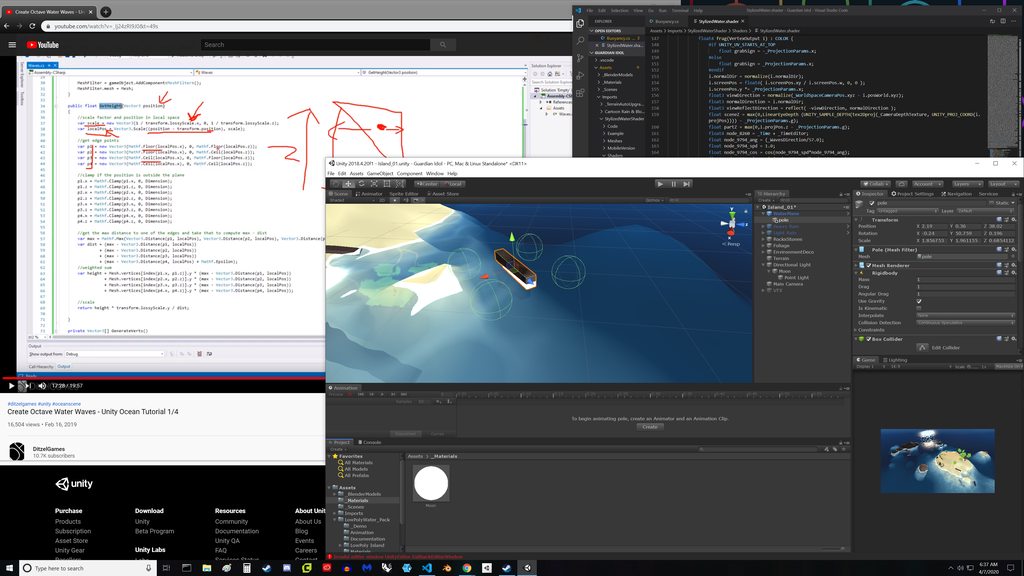
from collider to shader surface
The mesh is calculated on the GPU and isn't saved anywhere. You can't access it.
All you can do is simulate what the shader is doing yourself
In script
🥺
It's just a name change
it's a continuation
you can get URP in the package manager in Unity 2019.3+
@devout quarry thanks
Well... I might have to wait to hear back from the creator.
Otherwise, I could try this asset: https://assetstore.unity.com/packages/tools/animation/water-float-164693#content

Get the Water Float package from Pathiral and speed up your game development process. Find this & other Animation options on the Unity Asset Store.
or follow this tutorial and create my own water:
https://www.youtube.com/watch?v=_Ij24zRI9J0&t=49s

In this tutorial we will create a beautiful water scene. The tutorial is divided into 4 chapters. Every chapter will explain how a specific step to create this sort of scene.
In the first chapter we will create the water from a mesh. The mesh will be generated by c# code and...
@mental stirrup that asset uses a sinusoidal wave
so if your water shader uses another kind of wave, it might not match up
hard to tell since the asset page doesn't have a lot of information
I would follow that tutorial 🙂
Thanks.
I guess then... after I follow the tutorial, what do I research in order to create foam and masks and such?
How does one practice programming shaders?
just look for tutorials online
you practice by doing it
first, choose if you want to do hand written shaders or node-based
then look for tutorials
Yep. Only way to learn is to do it. Your google search phrase will help though.
Thanks for pointing me in the right direction
-or- I might purchase an asset that includes object buoyancy. LOL

Get the AQUAS Water/River Set package from Dogmatic and speed up your game development process. Find this & other Particles & Effects options on the Unity Asset Store.
Either way, thanks for your help.
Im gonna follow the tutorial and learn about shaders. Dangit...
There's always something else. 🙂
Any idea how to easily get screen uv from custom standard shader? (I took the standard shader and just edited the fragBase)
This is basically the shader:
            #pragma vertex vertBase
            #pragma fragment fragBase
            #include "UnityStandardCore.cginc"
            VertexOutputForwardBase vertBase(VertexInput v) { return vertForwardBase(v); }
            VertexOutputForwardAdd vertAdd(VertexInput v) { return vertForwardAdd(v); }

            #define COLORS 32.0
            uniform sampler2D _LUT;
            float4 _LUT_TexelSize;
            float _Contribution;
            int _ShouldDiscard;

            half4 fragBase(VertexOutputForwardBase i) : SV_Target
            {
                clip(_ShouldDiscard);

                float maxColor = COLORS - 1.0;
                half4 col = saturate(fragForwardBaseInternal(i));
                float halfColX = 0.5 / _LUT_TexelSize.z;
                float halfColY = 0.5 / _LUT_TexelSize.w;
                float threshold = maxColor / COLORS;

                float xOffset = halfColX + col.r * threshold / COLORS;
                float yOffset = halfColY + col.g * threshold;
                float cell = floor(col.b * maxColor);

                float2 lutPos = float2(cell / COLORS + xOffset, yOffset);
                half4 gradedCol = tex2D(_LUT, lutPos);

                col.rgb = lerp(col.rgb, gradedCol.rgb, _Contribution);
                //half4 col = fragForwardBaseInternal(i);
                //col = tex2D(_LUT, i.tex);
                return col;
            }
            half4 fragAdd(VertexOutputForwardAdd i) : SV_Target { return  fragForwardAddInternal(i); }
does anybody hase an idea why shader graph and gradient color as proprty is not working?
do you mean on the material inspector?
it doesn't apear on the material inspector and if you fill the property gradient color with multiple colors, unity will display this:
I didn't even connected this gradient property with anything. but using a gradient that isn't listed as property and everything is fine according to unity.
gradients are not a supported material inspector type, so it's not intended to show up on the inspector. https://forum.unity.com/threads/color-gradients-in-shader-graph.537831/
Unity Forum
Is there any way to use Unity's gradient editor in Shader Graph?
I've been playing with noise and come up with a decent-enough fire effect, but I...
Do VFX graph/shader graph teams work together closely? Some of the visual designs are really different
although maybe that's on purpose
we try, but we are based out of different countries on opposite timezones c:
but like a 'subtract' node or something, I would expect those to look exactly the same