#archived-shaders
1 messages · Page 144 of 1
I do have one more question
so right now in my 'Execute' method, I'm using this right
And so 'CreateDrawingSettings' takes a 'ShaderTagId' to determine which shader passes to render
But with your proposed methods, I would render shaders passes with ANY ShaderTagId right? How would I do that?
There's only a few lightmodes that the standard ForwardRenderer in URP will draw, which are these:
UniversalForward
LightweightForward
SRPDefaultUnlit
Ah so I'll make a list then
Okay that seems promising, will continue tomorrow. Thank you for the explanation and help
Hi! I have this setup. My question is why I have to use -.5 to make it all black instead of 0 if Im using a remap node?
Hey everyone,
I'm having a little trouble with unlit hdrp tranparent shader. I created a very basic one shown in the screenshot, but as you can see in the result, I'm not getting any transparency, just clipping. Anys ideas what I might be doing wrong?
@grand jolt I'm not sure how preview works (if that sphere is 1 unit) but is it possible that it's bigger than 1 so remap returns values below 0? can you try claming remap output for example?
@lost prairie Oh, the remap is on meters? I thought it was 0 the bottom of the model and 1 the top (in this case)
No, it's not in that range necessarily.
@grand jolt remap is just units but you're using object space y coordinate. remap doesn't clamp itself though so it can return values beyond given output range.
And there is a node that gets the heigth? Or should I create a variable and with a script get the size?
@grand jolt you want to make it fade in from bottom to top? admittedly I'm not sure if there's an easy way if the center of the object isn't at bottom (as there isn't height as you asked). but you can always make an exposed field and feed that from outside/material by hand if that works for you
Yeah, what Im trying is a fade from top to bottom, and in the fade section (between transparent and opaque) put an emissive line (like its dissolving from there). But yeah, if there is not a node Ill expose it, it will be easier that coding probably
@grand jolt another thing you can do, expose a field not for sphere size or bottom point but dissolve level (like in height). then in shader, subtract current position Y from that. negative will be bottom/visible part, positive will be top/invisible part. then you can do some smoothing and glow at edge as well etc etc.
Sorry I dont think I undestand that about substracting, do you mean to this? (Being 0 in the substract an exposable value)
@lost prairie
I have this shader from a tutorial that produces a distortion effect, but I'm having problems with it distorting objects in front of it too..
https://gyazo.com/d6a0a9f7b35a1e773daa72fc9ad3f91c
How would I go around making it only distort objects behind it? Only thing I see is scene depth, but it seems to act very weirdly..

Any ideas?
@grand jolt just to test, put a sign after subtraction and feed it into alpha channel. you'll probably see and udnerstand what I mean
@lost prairie Yeah! It looks like what I wanted! And sign works better than step here
It will depend still in the size but will work
@grand jolt sign might be overly sharp but you got the idea. now you can feed a value to change scan line directly which would help controlling it all 🙂
by sharp I mean sharp transition
Thank you!
no problem! have fun! 🙂
nice! 💯
I can't read your pic very well, but that gives you the scene color BEHIND the object** (you want to do that object in a later pass, like transparent pass).
You'll want to clip it against the depth buffer.
** = it's kind of like a grab pass though, so it's more like "underneath what you're drawing when you draw it" and that could be something that is in front of your object if it was drawn previously. So you need depth clipping.
@meager pelican This is the distortion part of the shader

I added the scene depth later but it didn't do anything
Correction:
https://gyazo.com/4f54bbab859af94573d18e415fccae7e?token=b055512d5bfdcf259dc2ce4d4214dc6a
It did this

objects behind the shader appear completely black
Also, it fixed the problem too
so now if there's a way to make it not black behind th black hole
that would be great
Hi guys! I don't know if here is the best place but I don't find a better one. I'm profiling the rendering performance of our game and it would be nice to have a good reference of some of my numbers as I don't find it anywhere on google. We are targeting on current gen consoles (ps4, xbox and a good tier pc).
- Which number of setpass calls are acceptable?
- Which number of batches are acceptable?
- Which number of shadow casters are acceptable?
In some places we have more than 3k setpass calls, above 4k batches and 10k of shadow casters. Obviously the cpu cost there is huge. The are trying to reduce it but if we have a number to compare, it would be easy for us!
What exactly is the difference between the Screen Position Node and the Position Node set to ViewSpace?
(HDRP ShaderGraph btw)
Screen position is what it says, position on screen
view space is position in camera space, so relative to the camera
that's my understanding but if I'm wrong I would love for someone to correct me
So you should see view space as the position of the object in the world
but measured relative to the camera (so camera as 0,0,0)
OH
And thus the Z component is always Negative
That was the underlying question to my question but now that makes sense
Thanks!
Positive Z means in front of the camera
finally 😄 https://github.com/Unity-Technologies/ScriptableRenderPipeline/pull/6360
https://user-images.githubusercontent.com/35328557/77520381-6f939180-6e81-11ea-9328-2fc60ef41b9b.gif

GitHub
Purpose of this PR
Adding a way to redirect / reroute edges is a must for keeping your graph organized.
Double click an edge or right click and create a Redirect Node.
It can have multiple outputs...

Oh dear god this is nice
I nagged about lack of this years ago 😄
then they put it on some roadmap but it's now finally there
well, as a PR anyway
And the scene depth (Eye Sampling) is a positive value based on how far away a vertex is from the camera?
(I'm sure plenty of people requested this besides myself as well)
And yeah
@valid flax
I believe this is the output of scene depth
so objects closer to camera, are darker
this is the diagram for it
so transparent surfaces are ignored
ye so close = 0 - furthest = 1
unless when in EyeSpace
than close = 0 and vertex = distance based on camera in units
right?
Also another unrelated question a Clamp node between 0 and 1 is the exact same as a Saturate Node, right?
or are there some differences?
Here is some more info that might help

Scene Color The Scene Color node allows us to sample the current Camera’s Color buffer – basically a texture of what the camera sees. However, it’s output varies depending on which Render Pipeline …
Saturate is same as clamp01
I prefer using saturate
"Returns the value of input In clamped between 0 and 1." is for saturate so yes
perfect! thanks 😄
@fervent tinsel do you know when the redirect is coming?
and will there be a 7.3/7.4, or straight to 8.0?
And 😮 the first commits are from July, they've been working on that node for a while
they have
bit like they've been working on URP deferred and SSAO for a long time
also no idea on the redirects target
Is 8.0.0 out yet on 2020.1?
it's totally possible to backport it all the way back to 7.x but it's another thing if they'll do it
yes
8.0.1 is on package manager
Okay neat, going to check it out then
and 9.x is about to release as well
9.x is still compatible with 2020.1 but I'd assume they'll make some hard cut for it working only on 2020.2 at some point when they need some engine API change that can't land on 2020.1 anymore
Hmm I'm excited for that roadmap talk then 🙂
I think virtual texturing and dots hybrid renderer v2 are currently 9.x exclusive
but they might backport them, I wouldn't know
hey, I am using the Universal Render Pipeline and I applied a texture on a game object. with the Standard shader, it looks fine. however, when I use the Universal Render Pipeline > Unlit shader, the game object appears pink
does anybody know how I can fix this?
@hallow shadow Then you're probably not using the Universal Render Pipeline
How did you switch to URP?
it was working perfectly before. then I removed some assets (separate assets, with no connection to the URP) and all of my game objects from the scene turned to pink
I switched to URP in the build settings menu
inside Graphics
If the Standard shader works, you're using the built in render pipeline
wtf
the universal render pipeline is selected in the graphics menu
might be some sort of unity bug?
Not sure
okay, I restarted unity, and inside the 'Graphics' window URP isn't selected anymore
I uninstalled URP and installed it again
but now URP doesnt appear in that menu anymore
Do you still have the URP asset in your project somewhere?
It's just a scriptable object you have to create.
I wanna remake this shader in shadergraph
actually only one thing i want out of it is the color + 1 outline with color
Outside of my sphere
Inside of my sphere
I enabled two sided in ShaderGraph
Why does it not look right?
I would expect my "inside of my sphere" portion to also be visible when i'm outside of my sphere
HDRP or URP @valid flax
Check that your material doesn't have zwrite enabled
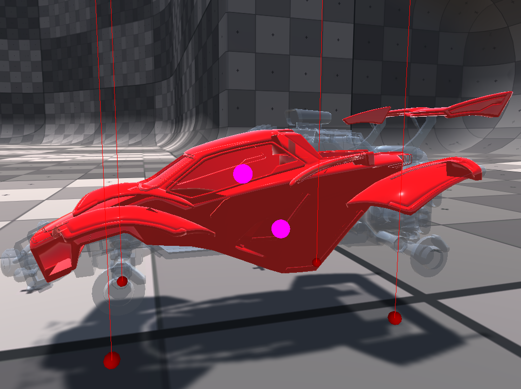
my question is not about shaders, but I have a problem with transparency, it looks weird with the "transparent" material. Is the model itself at fault?

No, the issue is how transparent rendering works in realtime engine.
I highly suggest that you separate the transparent and opaque vertices into different meshes/submeshes and thus, différent materials
I just wanted to make the whole car semi transparent for testing purposes. WIth the alpha channel being at max, you see weird stuff going with faces see through, I thought there was a problem with the model
What's the point à beeing transparent with alpha at 1 ?
Note that to fix your overlapping face issue, you can use "fade" mode
What's the point à beeing transparent with alpha at 1 ?
@amber saffron
to show the transparency looks weird, there is something wrong going on, its not how I imagine the transparency to work with alpha at 1. In 3ds max its not like this
I don't remember how it looks in 3ds realtime view, but it's totally expected that in the rendering it doesn't look the same : because it's offline rendering with raytracing and not rasterization
Like I said, if you want for some reason to draw a mesh that should be opaque, with a transparent shader, set it to "fade" mode
Note that to fix your overlapping face issue, you can use "fade" mode
@amber saffron
Still the same problem with "fade" mode

Is the mode composed of multiple separated meshes ? (body, tire guards ...)
in Unity the whole body is one single mesh @amber saffron I can import the model to 3ds max, but I wouldnt know what to look at
By default transparents don't write to depth buffer, what's the pipeline you're using?
That's built-in
And that's why I suggested to use "Fade" Rendering mode, as it's supposed to write to depth
hum 🤔
But seems it didn't resolve the issue, and that kind of surprises me :/
I tried fade its the same
By default transparents don't write to depth buffer, what's the pipeline you're using?
@grand warren
idk what pipeline it is, I am just using standard materials and the transparency is weird
I am a noob who needs help with this simple issue 🙂
This looks weird compared to real life or offline raytracing, but in realtime world this is kind of totally expected
And the usual fix for this is to split opaque and transparent objects into separated meshes
HDRP has a feature called 'transparent depth prepass' that fixes it
Whenever I create a new material, Unity assigns it the standard shader. Is it possible for me to change this? Kinda like how in HDRP/URP Unity assings the RP's default lit shader instead of the built-in one.
which makes sense that it would have to write to depth buffer before drawing any pixels
otherwise it could draw the back first
without/with transparent depth prepass:
This looks weird compared to real life or offline raytracing, but in realtime world this is kind of totally expected
@amber saffron
I am pretty sure any 3D modeling software package does this correct in the real time preview
I never seen this weird behavior in my life before. How can I fix it?
And the usual fix for this is to split opaque and transparent objects into separated meshes
@amber saffron
But I want my whole car to be transparent w/o weird clipping issues. I am sure Unity can handle that 😛
do I have to install HDRP shader? I think I dont have it
it's a whole new rendering pipeline, not just a shader
but you could probably take the idea and write a shader in the old pipeline to do it
yeh i dunno then sry
Its insane for me to learn to write sharders when this feature should come out of the box with any transparent material 🙂
it's not as simple as it sounds
because the graphics card can't know if the back faces are gonna be rendered first
so just writing to depth won't solve it (unless the front faces happen to render first)
games have proper transparancy for 30+ years, I cant believe Unity doesnt provide a proper shader for that
the pic above, how did you achieve that transparency effect? @stone ibex
did you write a custom shader?
transparent depth prepass with hdrp
does one have to code a shader for that?
no, but you have to replace/update all your shaders
standard shader doesn't work with it
(you have to use HDRP Lit, etc)
that's the settings to achieve the above
yeah
The Fade mode is supposed to do all this like I said
will it have a performance impact on my project or the run time?
The Fade mode is supposed to do all this like I said
@amber saffron
with HDPR right?
yes, most likely
fade didnt work for legacy shader
No, in built-in renderer
I mean, the issue you have is exactly what is described in the manual page : https://docs.unity3d.com/Manual/StandardShaderMaterialParameterRenderingMode.html

exactly what I need
"Fade - Allows the transparency values to entirely fade an object out, including any specular highlights or reflections it may have. This mode is useful if you want to animate an object fading in or out"
its still have culling issues
as seen in the video
Yes, I see that, and that's what bothers me here, it shouldn't
Oh : is it one mesh renderer with multiple materials set in the inspector ?
The grey and red, or two reds ?
lol, fade for the 2nd material worked!
yes, red and gray, let me show a video
not a video, but basically 2 materials and 1 object
I set both mat. to "fade", didnt help
fade doesn't even draw an opaque mesh correctly for me
but you said it should? 🙂
Is this model free to download somewhere by any chance ?
yep, its bad
I cant belive Unity cant do a simple fade with standard assets, I am speechless
I'm only rephrasing the doc The hologram in this image is rendered using the Fade mode, because it is supposed to represent an opaque object that is partially faded out. 😄
yeah but that hologram has the same problem
just less evident because it's less details
can tell in the foot easily
hum, true, didn't catch that
so no solution? I dont want to use HDRP, I have a simple project and need a simple fade transparency games use for over 30 years 🙂
I'm importing the car (or at least a similar I found)
this surface shader fixes it
from the default one it just adds line 13, and changes 12 and 18
an ultra stupid question, how do I apply this shader?
put it in your project, then it'll be under Custom > FadeSurfaceShader
yes, I have it in my assets. I think just drag and dropping it to the material 3d previews applies it
oh yea, its where you said it is
yeah not sure, i just chose it from the dropdown
omg its perfect now! I cant thank you enough!
it doesn't seem to have things like normal maps on that default surface shader though 😦

yeh cool
isnt it weird thought such a shader you gave me is not part of the standard shaders / materials?
I mean its pretty mind blown to me they dont have it
considering you changed only 3 lines of code
i dunno, a lot of things that are reasonably easy aren't built in
(there's so many combinations of what people want, it would be impossible to include everything)
he only changed 3 lines of code from the shader file template not from the standard shader
yeah that too, the standard shader is a lot more complex
well I mean many people would want a non culling fade shader, its not like its smth exotic so I would expect it to be included 🙂
anyway, thanks again for your help! @stone ibex
np
Hum, I was wrong, the fade mode only changes the global blending mode, it has nothing to do with z-write 😦
And I don't think a lot of people have the use to a depth prepass for transparent.
Well, at least in HDRP it's built-in now 🙂
it's useful for trying to make any kind of transparent 3d stuff really.. meshes look weird when you see some hidden faces
but yeah, it's not like it's impossible to implement (would be a bit more work to have normals and stuff but still viable)
Well, that's the point of transparent : you see what is behind the face. If you have a complex mesh with opaque + transparent : separate the materials
its just I was using 3ds max more then 15 years ago with standard materials and changing the transparency would give you what you expect in my video above - no culling. Its what you expect from transparency, I would have never imagined one has to write a custom shader for it
coming into this halfway through, I think you need to have transparency write to custom depth buffer
which should be a flag on the material
oh nope, that was suggested, let me read more
ah gotcha this is using builtin rendering
Complex transparent objects in front of each other are always a nightmare to draw. Normally you can sort objects by distance, but any non-convex object is still going to have places that break like above. Technically both results are "wrong" (depth prepass or draw order weirdness) in terms of how it should be rendered, but doing a depth prepass is more expensive and in most cases is not needed. I would be surprised if builtin didn't have a solution for this though
Hey peeps
Quick question
When you send a mesh into a shader (i'm making a run-time generated mesh in Unity)
Is it possible to send a single, small (a byte would be plenty) per triangle?
kind of like sending vertex colors into the shader
i just think it's silly to have to send 3 vertex colors for 1 tri, much rather encode 1 value per tri, can't really think of how to pass that data along with the mesh.
I really just need a performant way of sending a byte that can be converted into a color per triangle
Would i need to use a geometry shader just to be able to optimize, or should i just use the third value of a UV, or is there some way to pass custom data through?
My application for this is just that i want to make my run-time generated mesh have a saturation byte assocaited with each triangle. The triangle itself is shaded by the information of it's material, but the main colour is multiplied by my saturation value per triangle
@lofty gate You might be able to use SV_PrimitiveID to get the index of the current triangle in the fragment shader and use that to access an array that you pass to the shader.
But since the UV is passed as a float4, you're not losing anything by passing in a custom value in the z or w component of it.
oh so i'm using that space regardless?
If it's allocated as a float4 in memory then having data in it doesn't change performance
Ohh hmm... i technically wouldnt have to use UV data at all if my solution worked
The SV_PrimitiveID seems to only be accessible from within a non-surface shader
dang it
Has anyone else had issues with the shader graph exposed properties not showing in the inspector?
Found it.... you have to hit "save asset" in the top left...
Could anyone help me with a normal map algorithm? There are some deformities in the surface's normal. To the left is how it should look with a neutral normal map and to the right is how it actually looks.
And here is the code
bare minimum you're not expanding the normal value read from the normal map
also not sure what's going on with your TBN basis but that code doesn't look correct
Wait, could you please elaborate? I'm kinda new to computer graphics :s I was mostly following some tutorials
Sure-- so generally Unity is going to have all texture data as unsigned normalized (aka UNORM for short) values, meaning they're always in the range 0-1
however you can (and often will) have negative components
the workaround is to convert the range by scaling the value by 2 and subtracting 1, thus changing [0 - 1] to [-1 - 1]
you can just whap that at the end of your normal map load line
the second part (and this might be more subtle and/or your data is different from what I expect) but the way you send the tangent basis to the fragment shader looks wrong
I'm not sure why you're combining components from the different basis vectors
the tangent basis is actually the collection of the tangent, bitangent and normal vector
loosely the unit X, Y and Z vectors aligned to the surface of the mesh
fond of the mikktspace reconstruction since it's normalMap.r * tangent + normalMap.g * bitangent + normalMap.b * normal
really bop you over the head with it obvious
Okay, the conversion did work... partially. This is how it looks now:
is that with or without the basis fix
Without the normal maps:
    surface.normal.y = dot(input.tspace1, tNormal);
    surface.normal.z = dot(input.tspace2, tNormal);
    surface.normal *= 2;
surface.normal -= 1;```Is this right?
And what do you mean with combining components?
Oh, right, after loading the texture
unfortunately I have a hard time copying text since it's an image, but where you declare tNormal
    tNormal *= 2;
    tNormal -= 1;

    Surface surface;
    surface.position = input.positionWS;
    surface.normal = normalize(input.normalWS);

    surface.normal.x = dot(input.tspace0, tNormal);
    surface.normal.y = dot(input.tspace1, tNormal);
surface.normal.z = dot(input.tspace2, tNormal);```Oh, it works now! Thank you so much :)
Here's the end result, if you're interested
Yeah there are a few ways to (heh) skin a cat on the normal map conversion. I like Morten's approach above but there are a few ways to do it
I have a question: My game object only has different albedo textures. Something like skins. So do I create multiple materials with the different albedo textures attached to it or do I swap the textures on runtime based on player's seleted skin so that I only have 1 material?
the latter would probably be easier to manage. they'll have separate material instances either way at runtime
I'm wondering how they handle a dynamic object receiving baked shadow 🤔 . Those baked area shadow looks very nice
hmm lppv might work, need a dense probes on shadow area
they could have some trick to just sample it from the ground too (hard to tell if that could be the case from that gif)
Hey, I have this custom shader:
https://pastebin.com/hY06ejnJ
It will render the MainTexture based on object rotation and position in screen space.
The used this shader for my "fake" floor, which should only display shadows, the problem there is no shadows, any idea why?

The object itself does receive shadows, just when I use the shader the shadows disappear
By the way, I am using the new URP, so maybe something changed there? I remember it working before in the previous pipeline
@stone ibex ah that's make sense, using planar projection could work for this type of object
hi guys, how to make opacity map work on unity (the grayscale one)?, so need semi transparent material here (grey 50%)
I read that if statements are bad for shader performance, so should I rewrite things like these into using ? : instead, or does compiler handle it automatically?
if (abs(denom.x) > abs(denom.y)) {
    uv.y = (i.data1.x - i.data2.x * uv.x) / denom.x;
} else {
    uv.y = (i.data1.y - i.data2.y * uv.x) / denom.y;
}
AFAIK the difference isn't too considerable, at least for conventional programming languages. Not sure about something like HLSL/GLSL.
When importing a texture, there's an option to mark it as a normal map. What difference does it make in a custom shader code?
_SampleTexture2DLOD_RGBA.rgb = UnpackNormalRGorAG(_SampleTexture2DLOD_RGBA);
will be called
You can find those functions here
GitHub
Scriptable Render Pipeline. Contribute to Unity-Technologies/ScriptableRenderPipeline development by creating an account on GitHub.
That link you sent has no function called UnpackNormalRGorAG
Yeah that exact function does not exist
UnpackNormalRG does
UnpackNormalAG does too
But I mean, a normal texture (here I mean normal, not 'regular') stores directions, albedo texture stores colors
So it would make sense they need to do some processing to extract the data from the texture in a different way than they would process another texture
So you need to mark it as a 'normal map'
Oh, right 🤦♂️ my bad
and UnpackNormalmapRGorAG does exist on that page btw
so yeah a bit different name
but you can look at what it does
Hmm, it multiplies by 2 and decreases by one. In that case, marking it as normal makes that operation automatically?
Uhm I'm not sure exactly what marking it as a normal map does, I think it just sets a flag for that texture so that when it's used later in the rendering process, the correct data is extracted from it by calling some code
Hmm, okay
Now, another question - Yesterday, I believe, I asked here something about why my normal mapping algorithm wouldn't work. I just realized now that marking the textures as normal maps makes... Well, the result just isn't right
I'm pretty sure that if someone else were to use the shader I'm working on, they would probably use a texture marked as a normal map and it wouldn't work.
I just found out and yes, marking it as a normal map calls the UnpackNormal operation
The thing is, if I DON'T add a normal map the the surface's normal becomes all janky
oh, wait
If I don't add a normal map it looks like this
How could I fix this?
Oh, nevermind, it's not UnpackNormalRGB, it's only UnpackNormal
Yes, the *2 - 1 trick I explained earlier does the same thing
if you have both the manual version and the Unity-applied version then the effect will stack and your normal will behave strangely
Mhmm, I tried using that method but it was saying undefined
I didn't know I had to include a file, the tutorial on the documentation just slaps the function in there
them's some aliased pixels
I'm trying to come up with a joke about renaming the LOD biases or point filtering to Extra Aliasing
Hi,
I am new to shader programing. I was trying to write a shader in which when we select a _Color, that color becomes transparent.
.
I some how managed to write it, but its NOT perfect. How can I improve this code and add a tolerance so that colors almost identical to _Color also gets transparent
.
```fixed4 fragmentFunction (v2f IN) : SV_Target{
            float4 textureColor = tex2D(_MainTex, IN.uv);
            if(all(textureColor==_Color)){
                discard;
            }

            return (textureColor);
        }```
Please help 🙁
@cursive jewel I guess (abs(textureColor - _Color) < tolerance)
Hey , Er, I guess i'm in the right place :
I'm facing an error and don't understand how to solve it :
Assembly has reference to non-existent assembly 'Unity.Postprocessing.Runtime' (Packages/com.unity.postprocessing/Tests/Runtime/Unity.Postprocessing.Runtime.Tests.asmdef)
I imported a package and this error came out
Help please, if i'm in the wrong channel please tell me ^^
Okay I solved it with wtf things, unity is something bugged with postprocessing
Hi, this is my first time using shaders and I want to know how can I make this effect
Just a green effect, but i'm having difficulty with the Image effect shader
Does shader graph work with 3d
shader graph is only compatible with scriptable render pipelines (like universal or high definition), but not the built-in 3d renderer
if you are using iether universal RP or high definition render pipeline, shader graph will work
I'm having an issue setting a SG keyword by script
I have this in my properties
And the output is switched like this
so between texture/color
In my C# code I'm using Shader.DisableKeyword("OUTLINE_TEXTURE_ON"); and Shader.EnableKeyword("OUTLINE_TEXTURE_ON"); but there is no effect
Using this (global + exposed)
Doesn't work either by switching it in the inspector
Local + exposed does work
did you try unexposed global?
Yup I did
But I am doing this in some custom render code
hold on
Hmm I think the issue is not with the keyword, my bad
@low lichen The technique doesn't seem to be working
I have this
With drawSettings allowing the shaderPasses with the lightMode "SRPDefaultUnlit" to draw
but it draws the material to the render texture as if the keyword was disabled, so not with the texture I want
I have no idea why :/
Hmm, I'm wondering if DrawRenderers is maybe queued/async in some way
Ah yeah, it seems like it is
https://docs.unity3d.com/ScriptReference/Rendering.ScriptableRenderContext.DrawRenderers.html
Then how about doing it in a command buffer and scheduling that with context.ExecuteCommandBuffer?
@devout quarry
@devout quarry The example on that page shows it. Instead of the myCommandBuffer.SetViewMatrix(myViewMatrix); command, you'd do myCommandBuffer.EnableShaderKeyword("OUTLINE_TEXTURE_ON");
succes!
Now I can set the outline texture (red one) in the shader
So how come the command buffer does work?
commandbuffer is a way to make things happen before DrawRenderers?
Ah right "List of graphics commands to execute."
Damn they seem useful, will read up on them. Thanks a bunch
CommandBuffer existed long before SRPs. In the built in render pipeline, you can add command buffers to cameras to execute at certain events, like draw a mesh after rendering opaques. This was the basic scripting of the render pipeline that was possible before SRPs. Now they are mostly used as a handy way to create a list of graphic commands that can be executed some time later. You can also execute them immediately using Graphics.ExecuteCommandBuffer.
There are also some commands in CommandBuffers that aren't available anywhere else, like the CommandBuffer.EnableScissorRect. As far as I know, there's no other way to enable scissor testing in Unity.
It worked in this case simply because you were able to add that keyword enable into the internal SRP queue. Before, you were enabling the keyword, adding DrawRenderers into the queue, disabling the keyword, then sometime later the renderers are drawn, with the keyword now disabled.
Any idea how to update vertex normals in Shader Graph, I can update them with vector values but it does not want to be updated with texture 🤔
Use sampletextureLOD @merry rose
This is the key "This Node is useful for sampling a Texture in the vertex Shader Stage as the Sample Texture 2D Node is unavailable in this Shader Stage."
Ouu yeah, I totally forgot about that, thank you so much
Hey so not sure if this the right place to ask but: I'm planning on eventually putting some materials up on the Asset Store, and I was wondering what people's expectations are in terms of support for the different pipelines. Currently I'm working on a shader graph that allows you to customise the materials a bunch of different ways and such, but as I understand it that isn't supported on the standard pipeline which a lot of people still use (I believe?), so I'm guessing it would be good practise to also offer a version that uses the standard material rather then the customised shader, right? Also, are HDRP and URP shaders compatible, in that I only need to offer a single shader graph for both pipelines, or would I need duplicate versions?
Is there a way to tell why a replacement shader is just not applying? I'm trying a simple render to a depth texture.
For some reason it's just...not. The display is the same as if I wasn't doing anything to the camera.
@glacial parrot Are you using URP or HDRP?
Standard
Thing is, I have a far more complicated shader replacement working.
I really just need the depth texture, period.
And save that as a png.
Could I just access that?
The shader I'm using is exactly this: https://docs.unity3d.com/2019.3/Documentation/Manual/SL-DepthTextures.html
That shader actually throws a warning that the output is not fully initialized in the vert function.
Okay, I think I'm getting somewhere. Manually setting it (outside of my export function) to use the replaced shader makes the camera preview completely black.
Strange, it seems as though the macros don't do anything, and I have to to them manually.
No depth buffer, I guess?
Okay, just using Linear01Depth on the z position seems to do what I need.
In case anyone else comes here and searches for the answer
could someone help me convert this to rotate around a different axis? im good with matrix math and am just getting into shaderlab
{
  float alpha = degrees * UNITY_PI / 180.0;
  float sina, cosa;
  sincos(alpha, sina, cosa);
  float2x2 m = float2x2(cosa, -sina, sina, cosa);
  return float3(mul(m, vertex.xz), vertex.y).xzy;
}```
simply changing the last line to `return float3(mul(m, vertex.xy), vertex.z).xzy;` doesnt change anythingmultiply them
just like float3 rotated = vert.xyz * AngleAxis3x3(_DTime * 360, float3(1, 0, 0));? like i said, im horrible with matrix math and just got started with shaderlab
should be mul(your_matrix, your_vector)
thx
Hi all, I am trying to modify Unity's ProjectorLight shader. I would like to have a large orthographic size, so I can't affect a large area of GameObjects but also a "Scale" variable to control the size of the cookie it renders. I have tried applying a _Scale variable to the vertex positions but that didn't do the trick.
I have a grid I would like to have at a fixed size. When I increase the ortographic size the grid increases, which makes sense. However, I would like to apply a counter scale factor to it so it reduces in size. I have tried illustrating it with this gif:

A projector is pretty expensive because it redraws all the geometry it hits, so it can easily nearly double your draw calls.
I assume you need this grid to get projected onto the surface instead of just being flat?
I rather have it flat honestly, so each cell doesn't get warped. Guess I could just go with a plane.
Yeah, that makes more sense to me, just a transparent plane.
If this isn't for mobile, then you can get away with that overdraw.
Alright, thank you for screwing on my head 🙂
Its a compliment if you were in doubt
@regal stag i found a solution to my problem about shader system, all i do is use 2 camera: one for the game and one for the ui part
lol.......
now i got an interesting weird bug XD
one moment
ok, i fixed it but here how it happened if i haven't fixed it XD
I try to render a camera using RenderWithShader, and I pass them a shader that should color a shadow, but I cant get any shadow details from the shader, this is what I did:
Shader "Leap/ShadowPlane"
{
    Properties
    {
        _MainTex("Texture", 2D) = "white" {}
        _ShadowColor("Shadow Color", Color) = (0.0, 0.0, 0.0, 1.0)
    }
    SubShader
    {
        Tags { "Queue" = "AlphaTest" }

        Pass
        {
            Tags {"LightMode" = "ForwardBase" }
            Cull Back

            CGPROGRAM
            #pragma vertex vert
            #pragma fragment frag
            #pragma target 3.0

            #include "UnityCG.cginc"
            #include "AutoLight.cginc"

            sampler2D _MainTex;
            float4 _ShadowColor;

            struct v2f
            {
                float4 pos : SV_POSITION;
                float2 uv : TEXCOORD0;
                float4 screenUV : TEXCOORD1;
                LIGHTING_COORDS(2, 3)
            };

            v2f vert (appdata_base v)
            {
                v2f o;
                o.pos = UnityObjectToClipPos(v.vertex);
                o.uv = v.texcoord;
                o.screenUV = ComputeScreenPos(o.pos);
                TRANSFER_VERTEX_TO_FRAGMENT(o);

                return o;
            }

            fixed4 frag (v2f i) : SV_Target
            {
                float attenuation = LIGHT_ATTENUATION(i);
                float shad = (1 - attenuation) * _ShadowColor.a;

                fixed4 col = tex2D(_MainTex, i.uv);
                col.rgb = lerp(col.rgb, _ShadowColor, shad);
                col.a = shad;

                return col;
            }
            ENDCG
        }
    }
}
If you ignore everything but the lighting, what I did wrong that the attenuation is wrong?
I couldn't find any docs for LIGHTING_COORDS and such just snippets of code, if someone know where they are, please let me know, that would be great! (maybe inside AutoLight.cginc?)
Just for context: I render only a player and a plane under the player, for this question you can assume I only want to populate the alpha channel with the shad variable that is basically the player shadow
I get information from attenuation but not the player shadow
Hey, does anyone know if the built-in URP Terrain/Lit shader supports height-based blending from the alpha channel? I have the "Enabled Height-based blend" ticked but as far as I can tell that only uses the singular height value that you can set in the layer properties
I'm finally starting to learn some compute shaders
So far, pretty straightforward once you know a bit how GPUs actually work and how the workload is distributed
However, I don't get one thing about them
Let's say that I'm doing some compute work that I perform before doing, say, shadowmaps.
There's your dispatch method (in commandbuffer, for example). I schedule it and the compute shader is scheduled to be performed in async (via CommandBufferAsync).
Then I do shadowmap rendering with traditional shaders.
Ideally, this will provide a scenario where the depth shaders are not utilizing compute units to their full extent, so the compute shader's warps are going to be executed when the GPU will spot some empty/stalled threadgroups.
Now, here's the problem.
How do I actually achieve that scenario? How do I schedule the compute shader in a way for it to be truly executed asynchronously (so it wouldn't finish forcefully the moment it was scheduled) and how do I later wait for this compute shader to finish if I have to?
Hey, I'm kinda new to the whole Unity Shader graph thingy. So I'm trying to make a shader that just simply mixes two texture sets together and I need to animate it from one texture set to another. So is there a simple mix node that I could control with vector1 node, kinda same way I did it in Blenders mix node like this.
Lerp @wheat knot
Ah thanks :D
I have this weird shader glitch where the shader only becomes visible in the game view when im looking through the editor window, anyone see something like this before?
Works on multi pass rendering but not single?
Hi, I would need an HDRP Shader like this:
https://www.youtube.com/watch?v=j4J2QHr-cB4&feature=emb_logo
I could not find one on the Assetstore. Any ideas? Can anyone create that(paid)?

The Caustics Generator software is a program for creating animated caustics light pattern images.
These images are ideal for use as textures in real-time applications and visualizations of water.
This video shows footage of a real-time example of caustics textures used in the...
Shader Graph question:
could anyone help me with what kind of nodes I would need for creating a splat map shader like one for a terrain to apply different textures depending on the height of the vertices/angle of the slope kind of deal
Normal vector in world space will be you friend here @fluid pollen
I see thanks, testing with it now
is there a best way to layer the textures?
hmm actually let me test something
thanks for the advice!
Does anybody know how I can easily take a high-res image of a whole shader graph?
You can't
Last time I wanted a screenshot of a huge graph, I had to compose multiple ones in photoshop
Too bad
I submitted it as an idea to the product board. It's definitely a 'nice to have' thing for me, non essential but it would make sharing graphs a lot easier
Yeah, Substance Designer has this feature, it's nice
Hi, I would need an HDRP Shader like this:
https://www.youtube.com/watch?v=j4J2QHr-cB4&feature=emb_logoI could not find one on the Assetstore. Any ideas? Can anyone create that(paid)?
anyone?
The Caustics Generator software is a program for creating animated caustics light pattern images.
These images are ideal for use as textures in real-time applications and visualizations of water.
This video shows footage of a real-time example of caustics textures used in the...
@serene lintel
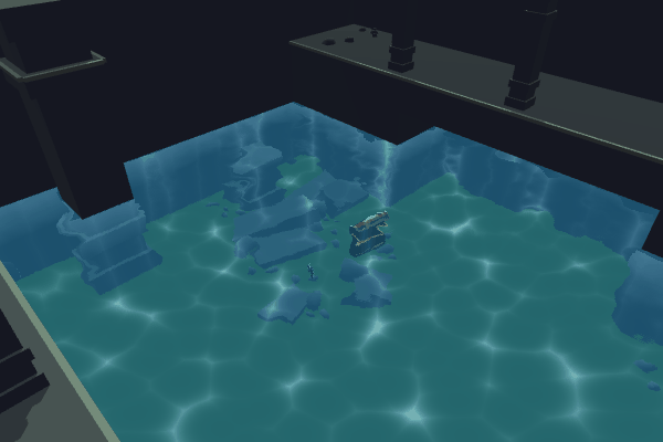
Intro This water shader is based on using the camera’s colour and depth textures to create transparent water with distortions/refraction. It also samples Voronoi using UVs of world space coordinate…
Here is a tutorial where they add caustics
maybe in HDRP you could use the projector component? But you could do the caustics as well in the shader and project them by reconstructing world space by depth (like in the tutorial)
When it comes to the visuals of the caustics, this might help

Learn how to create believable caustics reflections in Unity, using shaders. This simple tutorial is mobile-friendly and perfect for beginners!
Thank you very much! I can´t really do that myself because my technical skills are... not existing. But would you consider writing a shader like that for me? I would pay for it of course
The tutorial I linked is a start-to-finish tutorial, why not give it a try and see where you get?
I have a caustics shader but it's for URP only at the moment, could be converted to HDRP though I think but not sure at this moment
If you want to hire people to write this shader, you can check out Unity Connect https://connect.unity.com/
Unity Connect
The first talent marketplace dedicated to the full spectrum of Unity creators — game developers, artists, programmers, VR/AR developers, and more. Find game dev jobs, source Unity talent, and post tasks to get help on your Unity projects.
If I had the time, I would try it myself but I am very busy with a production. So it´s totally fine for me to outsource that
oh thanks!
I didn't know about unity connect 🙂
@serene lintel
one more thing
Crest was released for HDRP, it's far more than just caustics obviously but might fit your needs

Get the Crest Ocean System HDRP package from Wave Harmonic and speed up your game development process. Find this & other Particles & Effects options on the Unity Asset Store.
Thanks, I own crest already and they asked me to post the specific pool thing on this discord server. I have an ocean and a pool and need 2 different water types. That´s not yet supported by Crest (but will be coming)
Thank you very much for your help 🙂
Ok, goodluck
I am looking for some help to color my water within shader graph. i hoped using either a position node or the normal vector node but neither doesnt work for me. i want to make the top waves have a lighter color and the rest a darker color. but i am stuck on how to achieve this.
Can someone help/explain how i could achieve it?
How are you generating the waves?
with a sine wave
Alright, and in the master node, do you have anything plugged in there in the normals slot?
Personally what I would do is use a fresnel node to do the coloring
I'll show you what that gives, one second
Ty!
I hoped that i could have made them change color of the height useing the position node but sadly it didnt work like i had it in my head
you absolutely can, you just need to change the space of the position node to something like 'Object' and isolate a particular height range
working in world space is probably not the best idea for that type of thing
This is the result of the fresnel node, it's not exactly the 'top' of the waves being colored but gives a similar effect
I tried that but it didnt work?
@devout quarry Okay yeah i get the idea. do u multiply that with the color or emmision?
I don't multiply in my case but I put it ends up in the color slot yes
Il try that
huh
This is position node in object mode, and the y component of that
and then you can use that to lerp between color A and B
and so like InvalidPointer said you can remap/step whatever to get a certain range
also try a pow() to get more contrasty peaks
or just huck it in a gradient for full control
do u achieve that by splitting the position node and using the G as a Lerp T?
again, gradients are also a good choice here
yeah oke lemme try this
Yeah but gradients are not exposable in the material editor so a pain to work with
can probably just throw the position Y in there directly and ASSUME DIRECT CONTROL OF THIS FORM tweak to your heart's content
I don't think there's anything innately wrong with specializing the shader like that
maybe more of a problem if you're faking lighting
which, to be fair, we are
Modifying a gradient in the shader and having to compile the graph each time you want to see a change.. not for me 🙂
I'd rather have a lerp between 2 or 3 colors
So for me this doesnt work 😦
But i do have to say that i am on unity 2019.1 and in the LRWP 😦 its a internship project so i have to build it within these constraints
did you change the space dropdown on your position node
since it does not look like you did
(could also be a range issue, but first things first)
changed it to object
ok, so where are the bottoms of the wave in object space relative to the tops
are they all the way at the bottom of the object itself or is everything crunched around the middle
render pipeline should not affect this approach
how are you making the waves
using a sine node and absolute + one minus
And so you plug it into the position slote
so when you generate the color
are you taking the displacements you made into account
I now have a feeling you aren't
they are not magic, btw
ok-- was going to say that node just reads the model value
so if everything is the same color mystery solved
plane mesh
grok, but that's not what raikuns is doing
in my head it should have worked like u said Alex but it doenst 😄
but i completly understand invalidpointer his logic
makes sense
so if you were generating things and saving them in the mesh then you can do what Alex is doing
but doesnt the position node update live when u make changed to the normalS?
nothing wrong with it, might need it for CPU physics, etc.
If you change the vertex position in the master node, afaik the position node will take that into account
It depends if you're sampling the position in the vertex stage or the fragment stage. The position the fragment stage gets is going to be displaced by the vertex shader.
voila
And I assume it depends where the nodes ultimately connect to which determines what stage they are in.
actually, dumb thought
you have the displacement already
you can just throw that in the color blend directly
So after i use the combine node to add on the displacement. i feed the RGB into the position and the RGBA into the lerp. it works but not completly
The T property should be between 0 and 1. How certain are you that the value you're giving it is in that range?
I should clamp them then?
Anyone managed to do an outline effect for a given mesh on a scene using HDRP ? I looked at custom pass but it's a bit too complexe for my skills. I also tried looking at custom post process, but same problem...
or remap them into 0-1
@dire jolt No, better to use the Remap node. You have to know what the minimum and maximum heights of the waves are so you can assign 0 for the minimum and 1 for the maximum
@pine arch Other than post processing or custom pass, you could inflate the mesh based on surface normal
won't do 'inside' lines though
inside lines are a PITA ^
https://www.youtube.com/watch?v=_zICyYeM6IU this might help

This is a tutorial that show three ways to achieve the outline effect in Unity 3D using Shader Graph, sadly three of them are not that nice/good
Checkout my new Floating Islands Asset:
https://assetstore.unity.com/packages/slug/162431
Buy my LWRP Material Pack to support me!...
But definitely not my preferred way of doing outlines
those displacements are... not good 😐
thank you, but i already watched this video and the result is too random i think
For some meshes i think the inflating technique won't work very well
Then I don't know any other techniques. I think you'll need a custom pass or post process effect
The best i got for now is this custom pass example : https://github.com/alelievr/HDRP-Custom-Passes
GitHub
A bunch of custom passes made for HDRP. Contribute to alelievr/HDRP-Custom-Passes development by creating an account on GitHub.
dragging this old experiment out again
but i can't figure out how to edit the shader to increase the ouline width
need to consider more pixels
it's actually not a trivial edit
extremely straightforward for mesh approaches tho
@gleaming moss what techniques are you using on your example ?
hull inflation and some GPU warlock projection matrix tricks for constant sizing
also used MSAA for image quality
it's actually a one-liner-- just using the W component in scaling
note it is hand-written, though
all HLSL
but this technique needs you to use a custom shader in all the meshes materials you want to ouline, right ?
yes
not an issue in my case since you usually need that for cel shading anyway
it's an extra pass and URP magically makes the outline appear
literally no effort
Use a rendering layer mask then
editing the material would outline all the meshes using it
yes
@devout quarry i saw a Brackeys video about that but it was applying the same material to everything in the given layer
Ah yes MentallyStable, rendering layer mask, I implemented it and works perfectly, nice trick
Not much documentation on them though it seems
Are you trying to alter this one https://user-images.githubusercontent.com/6877923/66143724-f02ab100-e607-11e9-9fbf-af639112d17a.gif ?

i don't think this example worked on the last version of hdrp
or i just didn't figure out how to
@devout quarry Yeah, I saw that. Happy to see you got it working. There's also a trick I'm using to give the layers names instead of the default LayerX
i might need to try again i can't recall
Do you mind sharing how you achieve that? I'm interested
about the rendering layer way, could you give me a few more details on how it would work ?
just the theory
In a custom render pass you use something like this
Where renderingLayerMask is a uint
how ok you use rendering layer and custom pass
but you limit the custom pass to a render layer ok i see
@devout quarry https://hatebin.com/rmbvqazlhy
Basically the render pipeline asset has a string array property where it can define the names of these layers, but URP and probably HDRP too just return null, so it uses the default names
But you can inherit UniversalRenderPipelineAsset and override this property to give them whatever names you want
And you can also override stuff like default material that gets added to new game objects
Ah that's neat, definitely will use this
It's important that you name it the same as the original class if you want VFX Graph to work, because VFX Graph checks the name of the class to determine what shaders to use.
So it's a bit of a hack
ah yes, that excellent design decision
It could be done without this hack if they made one internal method public, but they haven't yet.
There's some thread about it somewhere
that's why I called it an excellent design decision
@devout quarry Oh and you need a custom editor for it also if you want the serialized array field to appear in the editor
https://hatebin.com/vqfkanwbfy
Or you could use the debug inspector mode
Or you can hard code the names in the script
@pine arch The selection example still seems to work for me :/


@amber saffron oh nice, then i guess i just missed something in the configuration, or maybe i just didn't figure out how to limit the effect to a specific object, i don't remember very well. I'll try again, thanks for the heads up !
just tried again @amber saffron, i'm having trouble reproducing the screenshot on github :
i have less options
The one you're showing is the fullscreen custom pass, that matches the one on the bottom. You need to add a draw renderers custom pass
oh sorry
i though because i got a fullscreen shader i needed a fullscreen pass
i'm not really understing everything i'm doing ^^'
better with the other custom pass, right !
This effect is made in two steps :
- render the desired object in a custom color buffer
- compose the outline over the rendering in a fullscreen pass
Great 🙂
Note that this is probably a very suboptimal method to do a silhouette, I didn't really try to optimize it 😄
it's the only way i found working on a modern HDRP version so i'll take it 😄
oh ! i see what you did
😄
funny way to do a border
Well, yes, if you put very high width values, you end up with this :D
You can increase the number of samples tough
perfect !
😄 i'm kidding, i just wanted to see how it worked behind the scene
i only need thin outlines so it'll be ok
Yep, ye old trick of dupplicating the object, and offseting it of X pixels 🙂
oh, i've a problem
it works fine in the editor view but when i play
i get the outline but the mesh disapear
same moment but in editor :
if i put a texture in the fullscreen material i get my mesh back but black unlit
@amber saffron any idea ?
i'll try to restart Unity maybe
oh really, thank you !
@amber saffron nevermind, i forgot to add my new outline layer to the camera culling mask... 😳
hey guys, ive been trying to follow this brackeys tutorial for something a little different but have not had sucess with it yet: https://www.youtube.com/watch?v=WiDVoj5VQ4c&t=618s

In this video we create an awesome Glow effect for extra flare!
► Check out Popcore! https://popcore.com/career
● Download the project: https://github.com/Brackeys/2D-Glow
● Get Gothicvania Church Pack: https://assetstore.unity.com/packages/2d/characters/gothicvania-church...
im basically trying to make a weapon glow right before it is picked up
im very new to shaders and this is what i currently have
however it creates this blob for the axe:
while i would want for the axe to glow
any help would be greatly appreciated!
i have no idea about the tutorial or the shader editor, but maybe the blob around the axe is good but just not "glowign"? e.g. a blending mode problem, additive? but i can only see black, then it would be 100% transparent and invisible.
If you want to do glow in 2d, i highly suggest you look into "bloom" post processing effect. it was expensive on PS2, but its very cheap on anything past 2010, including mobile phones.
bloom can work fullscreen (thats nice, too).
right so thats what the tutorial was aiming for
essentially you could write some shader that told the bloom to highlight this object
@velvet elbow I think it's a little misleading to call bloom very cheap.
so im just trying to write a shader that gets this object above the bloom threshold
@sinful ledge What does it look like if you connect the Main Tex sample node directly to Color?
Just to check the shader works properly without the extra emission stuff
I assume you don't expect it to be black, right?
@low lichen why did you say that bloom is not very cheap? are you talking pixel fillrate performance? or the complexity of programming it?
@low lichen pixel fillrate, even a mobile phone nowadays has a lot of performance. overdrawing a full-hd screen 5-10 times is really okay in 60fps. so if you dont want to bloom and postprocess your full screen (then you would need render target derived from your screen target, etc.) but instead just render the objects into a secondary render target and finally add this as a texture ontop of the screen, then thats not expensive anymore.
@low lichen correct
once the shader is on the axe i would like for the axe to glow maybe white for now
@low lichen even blurring the texture is not expensive, if you resize it down to e.g. 20% and then make 8 to 16 taps of blur steps, then thats not to much fillrate eaten.
I say it with experience developing for the Oculus Quest. There the fillrate is especially noticeable since the screen is high resolution and high refresh rate.
On that hardware, you're looking at around 4 ms just for bloom.
@low lichen especially the oculus quest is a beast, and can handle it easily 🙂 its actively cooled, and its shocking. i have now on the 2880x1600 pixels it has, with 4x AA my own "simple" shaders running, filling fullscreen (for tests). the shader does 8 shadow buffer samples to get smoothed shadows, then 5 texture samples + normal maping. and it runs at 72fps.
@low lichen in unity my experience is that the quest has rather issues with lots of draw calls with lots of vertices. so if you draw objects with < 50 vertices, dynamic batching works well and its easy to draw 40 objects. if you draw objects with > 1000 vertices, even though the total throughput of the hardware should be okay with 40k vertices, it will go way below 2nd frame, even down to 25 and less fps.
@low lichen what do you do precisely on the quest, that you say this takes 4ms? 4ms is A LOONG time and it sounds quite complex. do you have some kind of default foward rendering postprocess stack bloom? or have you tried doing things manually?
Nothing custom, just the post processing stack.
ah, that does a lot.
people usually say unity is "slow" when compare to other (custom, c++) engines.
thats bollocks. unity is very fast, but it does a lot of (nice and confortable) things.
you need to really do custom things to be sure it does what you need.
So it would be wrong to tell developers to avoid doing bloom on the Quest?
example: i have a space scene on oculus quest. what would you expect naively to be faster? a cubemapped skybox or clear color = black and then a very simple particle system that holds 9000 stars and renders them (tiny) as a sphere shape in the scene?
i think you are 100% right, that you can not have much fun on the quest by just using the forward rendering postprocessing stack. thats because this is (AFAIU) nearly always taking the current screenbuffer contents and then modifying this (e.g. for color grading). but exactly THIS is really slow on quest. you can google that, the retreavel of the pixels from the ram on the quest is slow here.
BUT bloom (fulslcreen) just means blurred colors additively put on screen, suiting to the existing screen content. it can also just mean what most PS2 era games did: you render twice, full content onto screen and then only (very few, basic) shapes into a black bloom texture. then you do your magic with that texture (shrink, blur, effects, temporal history, etc.) and finally you render that as a fullscreen quad (bilinear filtered, blurred) ontop of the scene.
thats what all FFXII etc. did already in 2002ish and it looked gourgeous.
But you have to wait for the whole screen to resolve before you can begin blurring.
no, not at all
in fact, you can render first into your to-be-blurred bloom render target.
(e.g. spaceship engine glow pfx)
then you can render your normal geometry
and while doing this prepare a quad fullscreen (e.g. camera aligned) with that bloom texture.
Then you should tell Oculus to edit their developer best practices article
https://developer.oculus.com/blog/down-the-rabbit-hole-w-oculus-quest-developer-best-practices-the-store/
but honestly, i think with 2 eyes, in VR, you want to avoid a lot of traditional 2d full screen tricks. i havent checked yet, but it might be that bloom ALSO feels strange.
the problem with VR is that your brain can tell VERY WELL if something is 3d or not. real "glow" around objects would need to be 3d, too. so physically different for 1 eye than the other. full screen bloom behaves very identical (e.g. blurring by 20 pixels) for both eyes, and that will make it look odd.
i know other 2d effects are shit in VR, i am guessing bloom, too. (but i dont have that experience).
@sinful ledge back to your problem 😄
🙂
@sinful ledge what you want, is that you have a predesigned glow around your object on the screen. maybe what you want is bloom. but maybe a simple PFX attached to the object is even easier, you have much more control AND flexibility?
It would be different for each eye because you're blurring both buffers. I thought you said you've done bloom on Quest with no issues?
e.g. with bloom it can be difficult to write temporal effects (fade in, fade out) but with PFX thats pretty easy, each particle has its lifetime and just dies slowly...
oh interesting yeah that might work
@low lichen it would be identical for both eyes, because you are blurring both buffers at once, with the same blur kernel. no, i havent done bloom on the quest. because in the end you are spending it from your "fillrate budget". and i rather spend it for other things (blurred realtime shadows, fake PBR, particle effects overdraw)...
how do you make the particles spawn from only the inside of the weapon?
Identical in what way? If you see something completely different in one eye from the other, the bloom would be identical still?
@sinful ledge also with glow it sounds like it depends on an event. e.g. pickup glow. drop glow. etc. then you want to couple the visuals with a sound. this is easy to be designed in the particle editor. much more work to make your own bloom animation in a shader, etc. i wouldnt do that. bloom is really for fullscreen "athmospheric" effects, e.g. constant afterglow from a space engine. etc.
@low lichen ah now, you got me wrong. if you see with your left eye a red object and bloom that and with your right eye a blue object and bloom that. then it would be correct.
but thats not the point, in 3d we are looking at something diagonally. a wall. on the left eye its much closer than on the right eye. now we bloom some glowy-lines textured on that wall. on the left eye the line is quite big and close to the eye, ont he right its small and far. now putting bloom ontop of that realistically you want 30pixels on the left eye and just 10pixels on the right. but bloom is quite uniform, as it depends on the bloom texture resolution, it has its minimum and a uniform blur kernel (e.g. fixed 32pixels) ... then you have it identically blurred in size on left and right eye.
so @low lichen lets come back to the conclusion you gave: lets not use bloom on a quest. but NOT because of pure performance issues, but because there are many other ways to spend the fillrate budget AND because 2d (fullscreen) effects on VR seldomly work visually well (it is unpleasing, tiring the brain and looks wonky).
@sinful ledge spawn particles from inside: google that, you need to attach the axe mesh as a spawner shape for the particle emitter.
I haven't had any experience with bloom being wonky in VR and I'd say most PC VR games use it.
FYI @sinful ledge there you nee to put the axe mesh
@low lichen interesting, care to point me to any youtube video where this is obviously visible? i have not played any PCVR to be honest, just PSVR and Oculus Go and Oculus Quest.
right i found that
so my game is 2d so i chose sprite
and even though my axe looks like that in the inspector:
it seems to be emitting from this slightly odd shape:
dont mind the scale
but i guess how do i make that shape line up more with the shape of the sprite
@low lichen basically, if you have a shitload of performance on a great rig on PCVR then obviously you can do bloom with a fine texture (e.g. 2048 texture to make sure you have a 1:1 on each eye). but if you sample it down in any way, then its quickly looking jaggy and that might be barely noticeable if you look at a full screen at FULL HD (1920) but if you have that resolution for 110 degree of VR and thus something like 15 pixels per degree, then any strange pixel artifacts will jump a lot in front of your eyes ...
thats the theorey, atleast.
@velvet elbow Here's a section in one of the Half Life Alyx gameplay trailers that shows a lot of bloom
https://youtu.be/LTLotwKpLgk?t=127

Return to City 17 on March 23, 2020.
Set between the events of Half-Life and Half-Life 2, Half-Life: Alyx is a new full-length game built from the ground up by Valve for virtual reality.
This video demonstrates the Teleportation locomotion style.
Pre-purchase on Steam: h...
@ionic brook have simply less blurry particles and control their position more, you just need to learn the particle basics and play with them a weekend i guess.
@low lichen great example, i will watch it now, give me a moment
@velvet elbow So you're saying that the cost of resolve can be completely avoided?
wrong luke haha
yes, but the sprite shapes dont match is my point like the shape of the axe at the top and the black wireframe dont match perfectly and i was wondering if there was a way to fix that?
Because the tiled renderer wont draw the entire screen at once like a desktop GPU would, so in order to do operations like blurring the whole texture, you have to wait for all the tiles to finish before you can continue.
It's hard to find any official documentation mentioning it, but you see it all over Oculus developer documentation
@low lichen watch the video at 2:12 and go frame by frame: the bottom right looks really really great, because the bloom is HUGE, quarter of the screen. so if that area is so big, i am sure even a low resolution + few blur samples will provide good results. but on 2:12 you can see that the bucket has a very small bloom area on top. there you can see that it starts to be not very precise and one would wish it to be nicer.
but i guess thats nit picking, definitely for this kind of reflection glare (sun into the eyes) effects that always want to be very strongly, this looks really good.
if i had that game, i would try this: find some glare bloomed, then slowly walk away from it, keeping the angle in a way that the glare should continue. i am sure they fade it out by distance /before/ the pixels get to little.
but you proved it right: this works and looks nice (in that 2d youtube video), not sure how it looks for both eyes, but i guess such a very rough glare bloom will look identical for both eyes AND it will just shine into the eye from similar angles, so its similar sizes... good example where i guess it would work well.
like even if the particles are super small and theres a ton of them, it doesn't really outline the axe
if it want for the particles to look like this: https://cdn.discordapp.com/attachments/497874081329184799/694280423148224583/Screen_Shot_2020-03-30_at_1.22.07_PM.png

@sinful ledge it seems that the axe image is mapped on a rough shape. then there is nothing you can do. and to be honest, i would just go with it and make the whole effect less precise and more "glowing"
Here's a bit of information on resolves
http://amd-dev.wpengine.netdna-cdn.com/wordpress/media/2012/10/gdc2008_ribble_maurice_TileBasedGpus.pdf
or make it model the sprite shape
@low lichen ah, good point. yes, Alyx for PC will most likely havesimilar tiling issues to solve. modern 2k VR capable gpus have tiling in one way or another, too. atleast some hierarchical things going on.
what you do here, is really do render into the bloom texture first, early in your scene. also this effect doesnt need to be precise, could even be 1 frame late.
then make the fullscreen bloomed quad be part of your normal rendered scene geometry.
or wait i could probably just make a circle glow that rendered behind the weapon therefore you can still see what you are picking up
exactly 🙂
like this but a better particle effect
@low lichen thanks for the nice PDF, helps me a lot 🙂 its clear, that if you want EXACTLY what is in your final screen buffer, to be then postprocessed, you have to wait for the resolve. ways to handle this is: effects that can work with the content from previous frame renderd, especially nice as with double buffering that surface is then free to render from. another way is to design your effects to simply NOT need exactly what will be in your final screen buffer ... and i am expeting this is what they do in modern (VR) games (like Alyx).
not using what is 1:1 in your screenbuffer has another benefits anyway, you will have 100% control over what you do.
@sinful ledge from a style point of view, i would use the sprite shape, offset the particles in Z to be "behind" the axe (black texture shape) and make them more "wide glowing particles" (very few, maybe 20, but 3 times as wide as the axe). then you get a roughly axe shaped glow, very big, lots of control AND your axe can be still visible without being obscured.
Hello, I do mean to interrupt any current assistance taking place right now just wanted to throw a question out there. Is anyone aware if it is possible to do light attentuation in HDRP when creating shaders. I know I can go down to the URP to make it work, but I don't want to lose advantages that HDRP provides. If anyone knows anything about this please let me know
(no idea, as a noob on deffered rendering / HDRP i would guess lights attenuate just the same as on forward rendering / LDRP ?)
something like that you think?
@low lichen anoher good example in the alxy video is at 3:29 the explosion. the bloom is very helpfull here, but its fast and large and again looking at it with both eyes equal distance (such large things most of the time will have equal distance to both eyes). i bet that they render the pfx in a very simple way into a bloom texture and thats nicely helping the shitty pfx to "fuse" together to a real glowing explosion.
@sinful ledge yeah, i like that - make it a bit more precise and be happy with it 🙂
if you pickup that axe as loot and it has rare or epic loot status, that kind of "over the top" glow would be exactly what you want to make the player happy 😄
ooh good idea
@velvet elbow ok im very close
how do i spawn particles when the particle system is initialized
since it currently rate over time
so it starts small and then gets to a good size like 2 seconds later
but i want for it to be at a good size when it is instantiated
There's the prewarm option
ah thank you
and would there be a way to fade the particle system in and out
like maybe fading the material in and out
yes there is
any one having issues with URP and InputSystem? the debugger is using the old input system...
@sinful ledge the particle system -> renderer -> material -> tint color (e.g. for shader: Legacy Shaders/Particles/Additive)
this will affect all particles being rendered at once.
but i wouldnt prewarm and wouldnt fade it like this, i would rather tune my glow effect in a way, that it starts slowly building app (over a second or two, not over a minute, obviously).
you can even make sparcles like that which appear slowly and randomly ...
babylon js has a new nice sample that reminds me of what you are doing now https://www.babylonjs-playground.com/#I6V1ST
Babylon.js playground is a live editor for Babylon.js WebGL 3D scenes
ok thank you!
hey guys im thinking of switching my project from 2018.4 to 2019.3 specifically for the new 2d lights/shadow stuff. I was wondering how different the shader programming is between the two versions are (i have some shaders that are cant be automatically converted, ive tried before), thanks
This is probably a pretty simple question - trying to display the outline of a mesh (a cube, for example) only. It doesn't have to be perfect, as long as its visible and can be seen through reasonably for debugging purposes. Is there a texture/shader/resource I should be using for that.
Hi! Is there anything particular to enable in unity shaders to enable rendering in both eyes for VR games? I have this issue with a shader that only renders in one eye. if it rings a bell to anyone..? thanks!
@gilded portal Yeah, sounds like a single pass issue. Are you using Single Pass or Single Pass Instanced?
There are a couple of macros you need to add in certain places to get it working in Single Pass Instanced
https://docs.unity3d.com/Manual/SinglePassInstancing.html
Is there currently a way to make a translucent shader for URP with shader graph?
Thanks I have to see if I can change that if its a project thing as this is a mod for existing game :/
@gilded portal Then it's quite likely that they are just using Single Pass and you just need to enable VR and single pass in your project
Unity will then compile your shader with single pass support
Okay so project already is set to that :/
@astral turret if you look on the asset store for an outline script im pretty sure i've used one on there for something quick and dirty
Is it possible to make a terrain shader using shader graph?
So I've done the bilinear interpolation shader for quads, but now it turns out that some quads might want perspective interpolation shader instead.
I'm currently thinking either:
-
Having two separate shaders and render them separately
However due to these quads having transparency and different depth values, it might need a large amount of draw calls.
Eg: quad 1 = depth 0, biliner; quad 2 = depth 1, perspective; quad 3 = depth 2, bilinear
This will require 3 draw calls as quad 1 and 3 cannot be batched together due to quad 2 in between. -
Having one shader that does both depending on input
Which will solve the problem of first approach, but will introduce dynamic branching to both vertex and pixel shader.
Performance here is the obvious concern (targeting as low end mobile device as possible), I'm wondering which one is better?
@regal stag hi. Can I ask some question about your post https://twitter.com/Cyanilux/status/1235537537428525056 ?
Is it possible to make a terrain shader using shader graph?
@vague kestrel I've done some in older HDRP, allowing for Parallax mapping etc. but in the newest it bugges out for some reason.
For me its the shadows that have issues, like building a big tower of terrain wont cast anything...
that tower doesnt cast anything, also that weird line shows up all the time
doesnt happen with the default terrain shader
How do u think, the gradient noise node is expensive for Mobile?
Any idea how to create heat distortion Shader Graph? I kind of need https://docs.unity3d.com/Manual/SL-GrabPass.html for that, I think, but there is no such graph node.
Scene color seems to be handy
@plush bane dude, Unity has a whole particle for that made
lol
Check the Particle Effects in Unity Asset Store
@plush bane Hey, What questions do you have in mind regarding that post?
I'm having a problem with a surface shader I wrote (for forward rendering). Everything worked great, but I wanted only the brightest / strongest light to influence a pixel, and not every light that the pixel is in the range of. So I found out about blending operations.
I added BlendOp Max to the shader, and everything looks perfect until something moves. It somehow seems to blend between previous frames and the current frame. What am I doing wrong?
it's a floor with a character walking on top of it. But because it blends previous frames everything looks smeared out.
@rose remnant Are you using some kind of temporal anti-aliasing? I can't think of many reasons why you'd be seeing previous frames.
No? Or is that something that might be turned on somewhere without me knowing?
No, probably not
Also, pausing and unpausing the game in the editor fixes it, but only until things start moving again.
You mean it gets stuck like this? Not just for one frame and then fixes itself?
It is set to Skybox
What if you set it to a solid color?
I'll tap out of this one, I can't do shaders for shi-
If I set it to solid color and make it completely black, it looks normal. Thanks!
Or is this not really how it should be?
I've never used BlendOp Max. It seems like it's messing with the clear operation, like the environment is more important than the clear so it can't clear.
But then you get ghost pixels remaining on screen
But I guess this is a valid solution? Or could this have unwanted / unexpected results somehwere else? (setting the clear flag to solid black)
It means you'll see black instead of sky wherever there is no mesh in the way.
hmm yeah I noticed that now
If you want to fix that, you probably have to reset the BlendOp back to Add (I'm assuming that's the default value) on all the pixels on the screen
You could do that by drawing a big transparent quad in front of the camera with that blend op set, probably
I will try that. And I guess if I wanted another color than black as my background, I could also just have a huge quad behind the whole scene with a certain color.
Btw thanks again for the help @low lichen !
@regal stag nm, figured it out by my self 🙂
Hey, asking anyone that can help, I'm trying to make a sort of watercolor effect shader and I'm trying to sort of dissolve the edges of a mesh in screenspace sort of like this, im having trouble figuring out the edge detection part if anyone could point me to the right direction it would be really helpful! thanks
When I change a shader property at runtime with code the changes do not show in game but they do show in the inspector. If i change the same value at runtime using the inspector instead of code the changes appear in game mode. What can i do about this?
I had to enable keywords.
@whole glacier I know you can do that with post processing effects, dunno about shaders though
I'm using this effect where I draw squares in a grid
I just use the base UVs
however when I rescale the quad, the squares stretch
so I tried multiplying the tiling with the scale of the object
but on a 3D surface this doesn't work too well :/
seems like you just need to tiling against triplanar UVs if you don't want it to stretch on object scale
Okay I'll try that!
you could use worldpos instead of UV to prevent stretching, and triplanar would help for rotation or if you use it on a cube. If you want to use worldpos but want the texture to move with the object you can offset pixel worldpos by object worldpos. You can get object worldpos either by passing through a script or calculating it in the vertex shader
@whole glacier Thats a neat effect, but that masking on only the outline edge is going to be a bit tricky. It would likely also have to be multipass. I would draw an object mask to a buffer, perform a large radius blur, subtract the original mask from the blur so you are just left with the blurred outline, then multiply that by a paint-splat noise uv of some kind and sample screenposition using the output as a multiplier. Not going to be quite perfect but might be a good start
ruh roh
It's just connecting in the third dimension, you can't see it.
I think I remember this getting fixed...ill look into it
ah, i just opened a PR recently to fix that bug
I thought so
ref name and display name actually need to match
Ah, will do
because of a kink in the material system
Hopefully you'll change that in the future
well, we can't change the material system
the fix we have in PR is that you can't make the ref name and display name mismatch
so that they'll always work as intended
awww no more 3d connections then
Hello! there is any node that does that but going from complete black to white in each tile?
Or any way to tile it (im not using any texture)
What are you using to control the original black to white gradient? Y position?
Yeah, its the Y position, green channel
I think you'll also get the same thing if you modulo the Y position before using it
Okey, so I have been playing with it and I ended up with this:
I would like to offset this part so I can animate it, where should I start? I tried with math nodes, but I dont find out how if it goes beyond 1 goes to 0 for example
try adding something to the inputs to see what that does 🙂
@simple frost Thanks for replying! Yea thats sort of where my mind went but im not sure how to apply that 😅, are there resources on multipasses and mask buffers?
I found it, I put a gradient node connected to the input of a Sample gadient
And the Time input is working the same as the Fac input in blender
is there a way to do a cut off shader where you render a texture at the intersection with shader graph?
yes, but 'intersection' is not a helpful description just by itself
intersection of what and what
and likewise we need to know more about 'render a texture'
hmm okay well I got it to work almost, let's take a sphere, I have it working rn so the closer an object is to said sphere or further away if I invert it, it begins to get evenly cut
with double facing turned on, instead of the cut being transparent, it's a solid colour, black atm
now I just need to figure out how to make that point where it cuts to be a texture
let me post a pic
so you're doing an alpha test based on distance in that shader on the sphere
it's doing a distance from cubes position and applying an alpha change yep
and want it to instead display a texture but not change the alpha?
I want it to do exactly what it's doing
is there any way to make the black there a texture instead?
it's only black because I enabled double face otherwise it'd be transparent
if there's a way to apply a texture to the double face that'd be great
other face*
the 'black' isn't actually black, it's shading
see the top portion of the sphere
it's casting a flat shadow down is it?
so you really want to make the back faces of objects use different shading
how would I achieve that?
shader graph is going to make that kind of hard
since you can't really 'opt out' of lighting in specific cases
hm
you can put a texture into an emission node
or slot
the other piece is the Is Front Face node
I would have that connect to both the emission and the 'lighting' textures (diffuse, specular, etc.)
you can use that to lerp the shading textures to 0 if it's a back face (and kinda sorta hack out lighting)
and lerp the emission to 0 if it's a front face
and kinda sorta hack out the emission
yw-- don't ask to ask. The more info we have up front the faster the advice
would it be possible to do a vertex displacement to create the textured plane where the cut is being done?
I'm trying to position vertices relative to another transform using the local-to-world matrix of the other transform assigned in a material property block, but am getting odd results. My approach is to multiply the local vertex position by the other transform's local to world matrix and then convert the new world position back to object space for the final vertex position. The vertex positions are scaled correctly but are positioned relative to the origin of the scene and appear to be rotated inversely.
Here's the script that's assigning the matrix to the renderer:
using UnityEngine;

[ExecuteAlways]
public class TeleportEffect : MonoBehaviour
{
    public Transform endTransformation;
    public Renderer renderer;

    private MaterialPropertyBlock mpb;

    private void OnEnable() => mpb = new MaterialPropertyBlock();
    private void Update()
    {
        if (endTransformation != null)
            mpb.SetMatrix("_EndLocalToWorld", endTransformation.localToWorldMatrix);
        if (renderer != null)
            renderer.SetPropertyBlock(mpb);
    }
}
And here's the shader:
And here's a video of the weirdness in case it helps https://streamable.com/ywq7i
tldr: Any idea why converting local vertex position to world space using another local to world matrix doesn't work?
@whole glacier unfortunately there's not a whole lot of resources I can find on it. I may write something up this weekend tho if there isnt a lot on it
@tardy spire have you verified the renderer is correctly getting the _EndLocalToWorld matrix?
Scaling and rotating the "end" object scales and rotates the vertex positions of the start object so it is getting the local to world matrix, but other than that I'm not sure how to verify