#archived-shaders
1 messages · Page 140 of 1
Lemme re-create your graph above. Sec.
So this:
Produces Yellow with Metallic at 1
It shows a zero in the screen cap, but 1 is yellowed too.
Just more reflective.
Maybe check versions and upgrade if you can??????
@dusk agate https://forum.unity.com/threads/uv-texture-coordinates-bounds-using-sprite-packer.400592/

Unity Forum
I'm writing a shader to make a colored glow on Unity UI Images like Fireworks/Photoshop Glow Effect. I found some examples on the internet and I can...
This will be helpful as I had the same issues
That is, if your Imagees are sourced from an atlas
Yeah, it's yellow with multiply too.
what version of unity do you have?
2019.3.3, but IDK that that's the problem, SG 7.2.1, SRP 1.5.4.
This is my sandbox proj, so I keep unity versions relatively up to current release.
What's your lighting?
A directional light, spotlights, what?
Maybe not.
Go to your lighting window, look at "environmental reflections" and check the intensity value. 😉 (Guessing)
0.284
Try putting it at 1 to test
I think you've got 100% metallic, dark skybox, and 1/4 value reflections! it's black.
So your reflection value ends up being near-zero, and then whatever you multiply by the color tint, it's still near zero.
What's your skybox?
Did you put the reflection intensity multiplier up to 1 and bake a lightmap?
Yep
And there's two multipliers...environment lighting and environment refection.
Geez, IDK.
Yeah, thanks but it's probably something very obscure. I might just drop the idea of using metallics for now.
Yeah, it should work. I'd need to check your metallic map settings. Maybe try to plug hard-coded values in for metallic and the 2nd color for testing purposes and narrow things down.
A fully metallic fully smooth white is basically chrome.
Try the reflection probe thing too.
hmmm, getting thre. I have hard coded values for everything now so can easily adjust
the 'test' ones are the hard codes
ok, I know what's causing the issue. I plugged them in one by one. My roughness worked, my metallic, my color but the color overlay killed it...
so if this is plugged in it works
but if I place my old overlay into it in shadergraph it breaks
Oh ok, so I picked your yellow tint for the hard code color overlay but my original was much lighter. When I picked your yellow for my original it worked. Sooooo it looks like my color overlay being lighter really threw it off. Which is a shame because I don't like this overlay for my non metallic materials. I may need to make a separate graph for metallic materials
Ok, figured this out. Created a boolean to over-ride the main overlay color with a custom color. So I just enable it when working on metallic materials and adjust it to something that works better with full metal. Thanks for the support!
I have been using HDRP for a while in my project, but the HDRP > Autodesk shaders are not appearing in the shader menu, even though there are in the hdrp package, any ideas why this might be ?
@stiff scroll they are shaders, not shader graphs. just make a new material and browse for HDRP/Axf shader
There are shadergraphs in the HDRP package for those
The axf shader is working, but I started a new project with HDRP, and there are the autodesk that I didn't find in my old project (that is also using 7.2.1
They are under packages > Runtime > RenderPipelineResources > Shadergraphs
They are even in a clean HDRP install
Let me check
You have to check "packages" in the search
Yup, they are also there on a clean template (and the shaders are appearing)
No idea what I should do, if creating again the library, unninstalling and installing again the package, those two will take a big amount of time
I just looked at the shader list and it lists those three shaders on new material
so they probably are just misplaced under shadergraphs (on the internal folder structure)
@stiff scroll
If I do a new HDRP template they also appear in the shader list, and are also in the same place in the package folder
No idea why they are not appearing in my old project though (I even have materials using the shader), autodesk, arnold and 3ds max don't appear either
@fervent tinsel in the project view, search for autodesk, and where it says search in "In assets" change it to "in Packages", you'll see you also have the shadergraphs there
hmmmm
I wonder if they just got left behind on some refactor
those files were on the initial PR here: https://github.com/Unity-Technologies/ScriptableRenderPipeline/pull/1881

GitHub
2018.3.0a9 adds new methods to the RenderPipelineAsset that the ModelImporter calls to find SRP shader implementations for FBX models with Autodesk Interactive materials ( formerly named Stingray m...
But do you also see them right ?
on the hdrp package, yes
The weird thing is that I have materials using the shader and they work, but for some reason they just don't appear on the list
It is though, just create a shadergraph and it'll automatically appear on the shader list
hmmm
those files in the gif I put
are those three .shadergraph files
oh
now I get it
these are shaders MADE WITH shader graph
you can open it
Not all of them, some are straight up shaders, and some are shadergraphs (some might be amplify shaders if you have them)
it's just PBR shader graph
well, these three ones are SGs
AxF is shader itself
so... what's the issue you are having again?
They don't appear on the list
On the material list xD
if you watch the gif above, they clearly are there
Not in my project, that's the problem
If I create a new template they appear normally, and they used to appear
so you don't have them on HDPR/Autodesk Interactive/*
and you use same HDRP version?
7.2.1
that being said, these have been there for a long time already
and everything else is working
Yup, I think I started this project using v5 or v6
and I have materials using those shaders and they work, but they just don't appear
In the materials I've done they appear, but not if I click on the list
how to control when a camera renders ?
private void LateUpdate()
{
    Debug.Log( "Late update" );
    render_state = 1;
    GetComponent<Camera>( ).Render( );
    render_state = 2;
    GetComponent<Camera>( ).Render( );
    render_state = 3;
    GetComponent<Camera>( ).Render( );
}
private void OnRenderImage( RenderTexture source, RenderTexture destination )
{
    Debug.Log( "Render Image " + render_state );
    Graphics.Blit( source, destination, material, 0 );
}
ah nvm got it, just removed the last render call
private void LateUpdate()
{
    Debug.Log( "Late update" );

    render_state = 1;
    // modify material shader ...
    GetComponent<Camera>( ).Render( );
    render_state = 2;
    // modify material shader ...
    GetComponent<Camera>( ).Render( );

    render_state = 3;
    // modify material shader ...
    //GetComponent<Camera>( ).Render( );
}

private void OnRenderImage( RenderTexture source, RenderTexture destination )
{
    Debug.Log( "Render Image " + render_state );
    Graphics.Blit( source, destination, material, 0 );
}
@sly breach Probably because the camera is enabled so Unity is still rendering it automatically at the end of the frame
If you want total control, then you can disable the Camera component.
The render method will still work
nice, just what i was looking for, cheers
Has anyone worked with the custom passes in HDRP? I am trying to highlight an occluded object (draw a color when ZTest Greater is true), however I can't get rid of the highlight due to self-occlusion of the object
This is the current setup. I have a custom pass set up that draws the highlight but as you can see there's also a highlight for the faces in the back of the object (as you would expect)
Here's where it get kind of weird. Using the custom pass feature I can move the GBuffer in the RenderQueue to a later stage which fixes the self-occlusion highlight issue but then I don't have any lighting:
According to this the behaviour obviously makes sense, if I move the gbuffer pass to a later stage it misses the lighting pass, however i don't understand why there is no depth information available in the after depth and normal injection point
I do hope this feat gets implemented: https://github.com/Unity-Technologies/ScriptableRenderPipeline/tree/feat/shader-graph/properties-exposed
just tried it
old setup:
new one:
that prototype feat still doesn't expose all feats from the master node to the shader but would be awesome if it did (or even better if they let you expose the specific properties on master node settings)
Are sharers a good way to smooth the edges of a low poly circle? i.e. the cylinder primitive, squashed in the z-axis.
could use alpha clip mask to make it round if the shape is like, flat there
should be trivial to do if that has UV
How close will you get to it? How smooth do you want your "low poly" to be? Can you support tessellation?
Otherwise, yeah, mask it. BUT you can do calcs for 2D radius and distance from center in worldspace, but if you need it 3D it won't meet up at the edges. You can make a mathematical cylinder instead of a mesh one though. You'd end up ray-tracing the object.
If it's 2D. For anything 3D, you need a finer mesh or tessellation. Or math/ray-tracing. Low poly is low poly. Smooth vertex normals will help your shading but won't fix the edge line.
I need a little help :D
I am using a Tilemap, with Tiles, and I would like to be able to make an effect almost like the "Fresnel Effect" applied to that group of Tiles, but instead of being radial and applied in World Space, I would like the effect to be applied to the edges of the group of Tiles and that the edges have a higher Alpha value and if possible even change its color. The general idea is in the image below.
Can you give me an idea of how to do this?
Thanks in advance.
The red, not the blue lines, right?
So you want a "maximal outline" across multiple objects. I'd think about either highlighting the tops and sides of the top row only.
-or-
using a post processing effect with a built-up stencil and somehow clipping off the left/right/bottom and only doing the top detection.
:2cents:
Yap, it's just the red ones.
Thank you very much for the idea, you saved me the day :D
I'm going to test it now and see what I can do.
Here's one way, it requires a double-draw, but you can "cheat" on one of them and make it very simple (like just a color fill).

Game Development Stack Exchange
I just had an idea for my on-going-game made with opengl in c++: I'd like to have a big outline (5-6 pixel) on multiple overlapping object when the player win something.
I thought the best way is ...
This is a bit of a general question but is there an easy way to add height maps to shadergraph? I'm working on a personal project, so not too concerned about filesize etc. Just curious, because my current pipeline creates heightmaps, I just don't use them and wondering if I'm missing out?
@meager pelican I'm afraid I'm shitcanning the bird game. The original time frame was 2 weeks but at this point preproduction time is over 4x that with how busy I'm with uni so I gotta pick something with a smaller scope 😥 Tried to make a small island and boi that stuff labourious.
Nothing is a waste of time if you use the experience wisely.
– Auguste Rodin
ok i think i am going nuts with this vfx graph. where the hell do i hook custom vfx shaders graphs to it?
oh wait. particle lit quad
....apparently not
...yes it is, there is TWO output particle quad nodes
thanks for that
people have asked about this on the shader graph forum, you could get more details there. you need to have experimental features enabled in your preferences, and to use the VFX master node in the graph you want to use
no i don't. that's the thing
or wait, do i? between fighting this godawful shadergraph i kinda forgot
Okay now i'm even more confused
void TriplanarUV_float(float3 worldPos, float3 worldNorm, out float2 Out)
{
    // Blending factor of triplanar mapping
    float3 bf = normalize(abs(worldNorm));
    bf /= dot(bf, (float3)1);

    // Triplanar mapping
    float2 tx = worldPos.yz;
    float2 ty = worldPos.zx;
    float2 tz = worldPos.xy;

    // Base color
    float2 cx = tx * bf.x;
    float2 cy = ty * bf.y;
    float2 cz = tz * bf.z;
    Out = (cx + cy + cz);

}```works fine on a cube. on a cylinder - i get this
hello Peps
i have got a question to you Sempais'
how do you understand the nodes you need to use? while making the shaders in shader graph?
im learning shader scripting for last 2-3 weeks and i actualy got to learn some basic math and when i want to use it
but how about the things like "screen position" "dot product" "cross process" "floor" etc etc
when do you know when to use those nodes while scripting a material?
i need to learn this kind of wizardry 😄
most of the time while scripting the shader im using various sources of ready visual script, for example Ue4 forums etc and mix it with various other lines of visual code
but when i open a new shader graph and want to do it from scratch i dont know how to do it just by myself
@urban oxide You need to think (sometimes, really hard) about "what do I want to acheive".
Only when doing this and visualizing what your final goal is, you'll be able to get what are the nodes you'll have to use.
Also, after you think about it, some nodes will be "helper" for you, ex:
- dot product => returns how much two directions are close to each other, or how much a vector "overlaps" an other
- cross product => give me a vector perpendicular to two others
- floor => used to make "10 steps" when I input a value that goes from 0 to 10
You can try to use an online tool like Desmos to visualise some of the functions.
Here for floor : https://www.desmos.com/calculator/u9zahins7j

Desmos
@regal stag i just found out why it's not working with the deferred render thing: URP is not compatible with it, only the HDRP can do it
that explain why it have that weird ass bug -_-;
that is where i found out: https://www.youtube.com/watch?v=5MuA92xUJCA

High Definition or Universal? Find out which Render Pipeline is best for your project!
► Get Milanote for free: https://www.milanote.com/brackeys2020
► Turn-based Combat video using Milanote: https://youtu.be/_1pz_ohupPs
● Feature Comparison Table: https://docs.google.com/sp...
and that list mentioned it too: https://docs.google.com/spreadsheets/d/1uoAjDCPOsGMf_Skk9-fmCNu_SBNdtrk3k78xBT-lHoo/edit#gid=0
now i feel annoyed
Does anyone know how to create shadows from a cloud shader like this? or could point me in the right direction?
@fresh spire Yeah, URP currently only has forward rendering. I don't think this has anything to do with your issue though.
right now there is shadow everywhere, its missing the "holes"
you need to discard in the shadow pass @long rune
Could you explain?
@long rune Is this made in shadergraph? If I'm not mistaken you can use the AlphaClipThreshold to discard transparent pixels, which should also affect shadows.
Otherwise as Peter mentioned, you'd need to edit/make a shadowcaster pass in the shader code.
Im using shadergraph, the problem with AlphaClipThreshold is that it sharpens the edge of my coulds
@regal stag i'm going to test out 2 game test, one done with HDRP and one done with URP
and see if that bug occure with HDRP
@regal stag It worked! thanks, however the edges seem a bit rough is there a way to feather them?
@fresh spire The setup in HDRP would likely have to be very different as we used the URP forward render features to achieve the stencilling effect. I'm not sure if HDRP has that, or something similar to override stencil values. Otherwise you'd have to write stencil operations in the shader code itself. Since your game is 2D/sprites-based, I doubt HDRP is the pipeline you want to use.
If we are still talking about the effect showing ontop of the game-over screen, it isn't really a bug, it's just how the URP forward render features work. As I mentioned before, you could use an additional render feature pass to ensure the game-over screen is drawn ontop of the effect.
@long rune No, shadows are basically 0 or 1
But you can try some tricks :
- Use dithering for your opacity in combination with alpha-test, this will make dithered shadow maps, that might end up looking "smooth" with the shadow filtering
- Don't project shadows from you clouds, and instead, use a cookie texture on you directional light 🙂
If i go with solution 1, how would i go doing that in the shader graph? sorry i know im asking a lot
I also came up with something like that, is there any way to smooth the dithering?
Hello all ! I am trying to use the shader graph in Unity 2020.1.0a25 HDRP + DXR to show a mesh with colors per vertex. I have a really simple shader graph but whenever I use the "Vertex Color" node I get a black mesh. Did I miss something ?
@long rune You can try to use jittering to do this, but it won't really work with the shadowmap anyway ...
@keen geode Are you sure that you have proper vertex colors ? Does it display properly without raytracing ?
Using shadergraph I'm trying to enable/disable a keyword with a button press
It works fine in the editor, but in the actual build it doesn't work?
I'm using this it like this
"material.DisableKeyword("ADVANCED_LIGHTING_ON");"
where the keyword is a keyword created by me
If there is no material with the enabled keyword included in the build, it got stripped out
Ah, is there a workaround?
Or should I just make the 'default' setting 'enabled'
I'll enable it in editor, then build, and turn it off on play
Alright that works!
Thanks
Or, did you use the #pragma shader_feature directive ?
Nope I didn't, just a keyword in shadergraph and material.EnableKeyword
But is there no way to force the variant to not be stripped out?
You should use #pragma multi_compile : https://docs.unity3d.com/Manual/SL-ShaderPrograms.html
And how would that work with a SG shader?
@amber saffron I tried to disable the path-tracing mode and I can clearly see the vertex colors
OOOh, so it's path tracer, not "simple" only DXR
Indeed 🙂
Noted, thanks, I'm reporting it.
Path tracer is still kind of in early preview tough
Thanks !
Another question, I am looking for a way to manually/by script reset the DXR framebuffer. When you move the camera, the raytracing computation restarts. How do you trigger that by script ?
This is stated
on this page
Under what does 'Vulkan' fall?
Direct3D-like or OpenGL-like?
iirc, D3D-like
Hello, I'm following a book on shaders and there is this syntax, the dot product gives a scalar, so what value takes the float3 specularDot? Thanks!!
@river dawn If I'm not mistaken, it assigns the scalar/float value to each component of the float3.
@river dawn If I'm not mistaken, it assigns the scalar/float value to each component of the float3.
@regal stag Ok, thanks!!
Why would my shaders be behaving differently in my build?
A better picture
Ok now seriosuly
what even happening
no errors on graph. it compiles. it shows preview
try to make material - magenta error
Render pipelines, ladies and gentlemen
OH. WAIT.
it doesn't copy over custom function nodes completely
...so it does but then it just breaks.
all these undercooked systems which got thrown into "not preview" just ready for use
Kinda reminds me of early unity3d hub which just broke and didn't work at all
Oh ok nvm so an empty unconnected node decided to affect all the connected ones on compile time instead of being discarded/commented out in compiled code
Thanks for that, this is stupid
no warnings also
can someone actually go ahead and hit these new devs a few times until they learn to properly write down all the warnings and errors?
hey, please remember to civil and respectful in the channel. if you're experiencing an issue that you think is a bug, filing a report via the editor is the best way to make sure the team can see it and fix it for you, or point you to a package version where the issue may have already been resolved c:
@stone sandal Hey, i hate that the engine i am using to put the food on the table and been using for past 9 years going down the shitter, and i have every single right to be upset that new features are a messed up trash which suggests lacking QA
in any case.
after fighting over the problems - particles seem to be working
would be a good 3d core akin to ps1 era effects
can always update it later
You actually do not have the right to be rude and insulting on this platform. 👋
@smoke_th#3764
Do you know a software or game that doesn't lack QA?
We never have enough QA
Stick together, be a strong community.
Report those things.
Hi everyone. I have some toruble with my texturing. I have a difference between my color of my object but it's the same texture in the two object is anyone know why ?

as you can see I have a differente black in the main rock and in the stalagmit... :/ It's look like it's a normals probleme but I try differente think and nothing change ...
Have you tried using the HDRP debug menu to identify what is causing this difference in "color" ?
Is the albedo in the buffer similar ? Normal difference ?
No we don't but now yes 🙂 I check the color and the normals. The color is okay but the normals looks like little bit difference.
We just try to delete normals and also the details maps. And it's look like the problem come from the normal detail
Why does this shader shows through the model? I have setup the correct alpha channels but still is show trough
Let me guess : The shader is applied to the whole object, trunk + leaves ?
If yes : you're using a transparent shader that doesn't write depth, resulting in overdrawing.
You should either separate trunk in a opaque shader and leaves in a transparent one, or use a global opaque shader with alpha-clip
Hey, I've been googling a lot about shader trying to figure out this answer.
I know if statement need to be avoided. I've seen people suggesting lerp step instead while some people that seem more knowledgable say step does an if statement so the result will be the exact same as doing an if statement.
Now i was wonder what about comparison.
Instead of
if (x == 0) {
  y += 5;
}
You do
y += 5 * (x == 0);
what exactly?
you want to be able to replicate what's shown on the picture with a single shader?
unless i'm missing something, That picture shows particle effect and stuff, that's not what shaders are about
@edgy vigil You should look at what each of those get compiled into
It might even differ between OpenGL and DirectX
i dont have access to that, i'm talking shader in general, i'm not a unity user
but i guess you mean it depends on the compiler if it optimises it or not
all i can get is that if and step both create branch which will be done both ways no matter what.
I mean i dont see why a (x == 0) check would create a branch but i just can't be certain.
@edgy vigil I want to create a rotating rays. That's about it
so just a spinning ray texture with shader?
@edgy vigil but is it possible to create the rays using shader? So that I can control the number of rays and length of it
i mean im sure its doable if you make your shader very complex, but i dont think it would be worth
you can do that with vertex shader
but you want to avoid feeding it a texture?
doing a simple gradient in fragment shader is pretty simple
i've never really delt with vertex shader, can you create more vertex with uniform values?
That sound complicated... let me try it first
I think if you want to create more vertices, you are looking at a geometry shader, (though I have never looked into them). Vertex shaders only manipulate what is already in the mesh.
yeah that's what i though
the shader is for UI
you can just draw anything anywhere and modify its position based on uniforms
is there radial tiling in unity's shader graph?
You can use the Polar Coordinates node to get radial coordinates, which might help with what you want to create (in a fragment shader). Personally I'd probably just use a texture though.
at the end you won't be able to prevent yourself from drawing the polygon individually
and for texture i dont know if using a texture would be better, i think it would be faster, sacrifice vram for speed. but its a very simple fragment to replicate a single Ray
The simple rays shader is here which I found online
but it uses amplify shader
does it use a texture too?
Looks quite simple to replicate. They are mostly just math based nodes
It does look like it uses a texture at some point though, not sure what texture that is since the node is empty
would anyone happen to know where I could find a massive collection of unity shader lab shaders
@edgy vigil if your code can be 'rephrased' to something like step() then don't worry about if(). However it's very very important to note that GPUs do not follow the same branching rules as CPUs so it's almost never a performance optimization
I need atleast 1000, and probably a lot more than that
the ray is just an half circle gradiant cut in half and elongated
probably the txture was added in properties in the inspector? idk
@tall chasm Most of the green nodes look like input values (like Vector1/Vector2/Color etc properties)
@gleaming moss what about comparing 2 numbers thought?
@regal stag ok I'll try to understand it. so radial tiling is polar coordinates in unity?
@edgy vigil every GPU ISA I know of does that as a cheap conditional select, as in it's cool. That does also play into the second part, incidentally, but for the examples you posted don't worry. Things like if(pixel_value < 0.5) pixel_value = DoExpensiveThing() are hard antipatterns
DoExpensiveThing() won't really be 'skipped' in the way the authors usually think
@tall chasm Nah, their green 'Radial Tiling' node is just a Vector1 property, between 0 and 10. That said, a lot of the maths involved in this shader does look like what the Polar Coordinate node already gives you.
Do you have an output image of what this produces? (ah nvm, found it)
yeah i understand that what's inside an if statement will happen no matter what
^^ not true, actually, but it's the safer assumption
i had a shader with bunch of if and else statement and i manage to just remove all the if statement by doing stuff like i_true = (x <= 0.5);
@regal stag https://www.youtube.com/watch?v=cjBMEgS-lsk this

An example of a simple UI rays shader made in Amplify shader editor. We're making a game called Pico Tanks - Multiplayer Mayhem and we often create fun stuff that we want to share with the community. https://i.imgur.com/3PvXrAc.png
This project was built using Unity 2019.1.0f...
@edgy vigil compilers can do that sort of thing for you, just don't go into the authoring assuming skipping things per-element is a useful performance pattern. The atomic unit of the GPU is the batch, not the element. It's not slower per se, just doesn't save what you think it does and the test(s) are also instructions that count for speed 🙂
this makes a little more sense if you know actual GPU ISA and conditional move instructions but I'll openly say that's a more complex topic
ok
for example AMD/NV hardware both can make bitmasks for lanes where a value is above/below a certain other value and use that to combine lanes from other registers. That's how the H/W implements the if(x < 0.5f) y += 5.0f, but ultimately you compute both sides and pick the right one per-lane
if you optionally do an expensive thing, you always do the expensive thing
@tall chasm Hey, something like this might help. (not an exact copy to the one you posted but might be a good starting point. I'm using Random Range to produce random numbers rather than using a texture lookup).
(Value of 30 defines how many rays, the power with 3 is the falloff).
i see what you mean thought but. i had a shader while back, it had a few if statement, simple code. i benchmarked it and changed it, did some complex math instead of if statement. like the math was way more complex.
but it turned out like 3 times faster or something
that might be compiler stupid, offhand. Speaking of texture vs. ALU-- the other way to kill perf is to hit memory repeatedly
don't do in a big texture what you can do with a little texture, and don't do with a little texture what you can do with a bunch of ALU.
yeah that could definitely be
it was a simple shader for 2d sprites
that drew a pixelated outline around the sprite
do do in a texture (hehe doodoo) what is expensive on ALU and can be run while you're doing other computations so you don't have to eat the barrier instructions
and i have if statement for each 4 side of a pixel
and i ended up just doing the whole math instead
4 times
yeah things like saturate or absolute modifiers can also make certain thing significantly faster
since they're almost always free things that can be coissued with the actual instruction
@regal stag can unlit graph be used for UI? I tried and it's not working
I'm using sprite unlit graph instead, but it doesn't have an alpha property on the master node
@tall chasm The Color input on the Sprite Unlit Master also contains the alpha part. You'd have to do something like : put it into the W input on a Vector4 node, then Multiply it with the colour (making sure the color's alpha isn't just set to 0).
Yea that would work too
Ok I'm trying to play around making the rays more uniform now
tried to say thank you 😦
I don't usually allow direct messages. But thanks. 🙂
Ahh ok no problem!
If you want very regular rays, you could use a sin function instead of random
Or, more optimized : frac
@amber saffron will give that a shot
@regal stag and @amber saffron thanks so much guys! Got it to work great 🙂
I'm trying to get an outline shader working. Basically flattening an object from the camera's view and giving it a border. I've searched far and wide but none of the solutions I found seem proper. So now I'm here, asking the pros 😄
The unity editor already outlines objects when I select them, so hard can it be? Or are those words blasphemous?
Not blasphemous, but the editor has it's own way to handle selection and outline, that is totally ignored by the more "regular" rendering
To make an outline you basically have two solution :
1.a) For a mesh, draw it with reversed culling and "push" the faces outside, then render the regular mesh
1.b) For a sprite, directly draw the outline in the shader, on the sprite's quad, using either multiple samples per pixel "get" the outline, or pre-bake the outline in a separate channel/texture
2) Draw the object to a separate buffer, and use it to compose the outline on the rendering as a post process
Hm, which is best?
Is there a "best"? In terms of performance that is
I just want to be able to "highlight" objects, see the player behind walls etc.
Disclaimer: I'm very very new to shaders.
They all have their pros and cons ...
What render pipeline are you using ?
"I've just made some waves with time and sin()" new
URP for my sandbox.
Where can I find the pros and cons? I'd like to learn them
Have you looked this tutorial ? https://www.youtube.com/watch?v=szsWx9IQVDI

Let's learn how to render characters behind other objects using Scriptable Render Passes!
This video is sponsored by Unity
● Download Project: https://ole.unity.com/occlusiondemo
● More on Lightweight: https://ole.unity.com/lightweight
·····································...
or this one : https://learn.unity.com/tutorial/custom-render-passes-with-urp#5ddc3f73edbc2a001ff7d6bc

Unity Learn
In this tutorial, you will learn how to use custom render passes to render a toon outline post processing effect on selected objects
I don't have premium
I think I've seen the other one because I watch all brackeys videos, but lemme check 😄
For the second one, here is the link to the example project, might help you : https://github.com/Unity-Technologies/UniversalRenderingExamples/wiki

GitHub
This project contains a collection of Custom Renderer examples. This will be updated as we refine the feature and add more options. - Unity-Technologies/UniversalRenderingExamples
The toon outline even showcases both methods
I was planning on getting the premium stuff at the end of march, which is when I will be learning unity stuff full time.
Saved up during my freelancing for about 4 months of full time learning. I think I can get pretty far in four months. Or am I ignorant?
That video is really helpful. I can google fresnel but I have no idea what "depth" does.
Also, I don't know what "Lightweight Pipeline Asset" is now. Is that UniversalRP-HighQuality? And does that mean the type was replaced with a list?
the Lighweight pipeline asset is now the universal pipeline asset
I don't have a file by that name
I created a new project in the hub, 2019.30f6 using the universal project template
Oh, ok, sorry, that's the type name. I guess that indeed you can use the one you mentioned
Oh dang it's different.
They renamed it but it's still the forward renderer I suppose
Ah, got it working. Cool. Still no outline but this is already pretty neat
What's "Blit"?
Where can I find that option?
It's a custom render pass that is included in that repository
Ah
Of course. Sorry
When following that video I get a different result in one of the first steps. My sphere (using that to test) becomes seemingly transparent
Outline is disabled in the Default Layer Mask option
I have some issues with my shine shader. This is what it is happening
my button looks like this
this is my graph
I would assume this has something to do with the sprites / UI "Image Type" setting
There are 2 issues that I can't seem to fix.
- If you look at the normal button, there is a 50% opacity shadow (that's how I saved it from photoshop) below my button. But with the shine shader applied, it turns solid black.
- I don't want the shine to cover the whole button. I just want a small shine swipe. Even the shine staying on the edges looks a bit weird
@regal stag Hang on let me show you
source image texture and shader texture is the same
To remove the edges you'd have to mask the shine with the sprite. e.g, taking the R, G and B outputs, add them together and step the result might work. Basically just to get where the black pixels are in the texture. Black means 0, so you could multiply that with the shine effect to remove it where those pixels are.
Meaning that will only affect the yellow parts of the button and not the black outline and its semi-transparent drop shadow?
Correct
As for the semi-transparent shadow, your other texture likely contains alpha values, so when you add them together, you are also adding their alpha values. You probably want to multiply the shine effect with (1,1,1,0) so it doesn't affect the alpha in any way
Ok let me slowly digest that and try it out
(or take the R,G,B outputs instead of the RGBA one, and put them into a Vector3/4).
Also, as you may have noticed the shine is quite squashed / slower on the edges than in the middle of the button. The UI "Image Type" setting on the Image component, makes the button look better when set to "Sliced" (assuming the sprite is set up to support it too), but it edits the UVs which is what is causing this. It actually doesn't look that bad, but if you want the shine effect to stay constant you might have to use the Screen Position node as UVs instead. (that'll be based on the full screen pos though, not just the bounds of the sprite).
@regal stag I'm using your screen space uv nodes which you provided me a couple of months back
The shine is constant now and the semi-transparent shadow is not affected. But I can't figure out how to get the shine to only affect the colours
To remove the edges you'd have to mask the shine with the sprite. e.g, taking the R, G and B outputs, add them together and step the result might work. Basically just to get where the black pixels are in the texture. Black means 0, so you could multiply that with the shine effect to remove it where those pixels are.
Using colour mask?
The Color Mask node would work yeah (although if you mask with black as the colour, you'll need to invert the result with a One Minus node). Or something like this might do.
Is there a default texture assigned to the Texture property, in shadergraph the blackboard?
the default is the checker texture in shadergraph the blackboard
If you assign the texture used for the button as the default, it might be easier to see the result in the previews
Oh god... I didn't know that.. I kept going back and forth lol
What I put above what to produce a mask for the colour result from the texture sample though, not to replace it entirely. You'll want to multiply the RGBA output from the texture sample with that Step
oh wait no
You want to multiply it with the shine output not the sprite texture output
(So the black pixels of the sprite texture, affect the shine result). Hopefully I'm making myself clear, I'm even confusing myself at this point. 😅
I'm trying to slowly digest haha
but this If you assign the texture used for the button as the default, it might be easier to see the result in the previews is helping a lot
Yeah, it's good to keep in mind that the previews always use the default values in the blackboard.
👌
Hi, i need help for my fogshader for underwater. I put my fog shader on my camera but the problem is that I have a panel for a submarine which is transparent, but the problem is that we only see it if there is an object behind but otherwise it disappears.
Hey guys I want to make a 2d sprite emit light at the border. Does anybody have an idea of how I could do this?
@gloomy oasis I assume you are talking about the fog shader disappearing. Sounds like it's because your fog shader uses the depth buffer perhaps? And the transparent panel doesn't write depth. Might be able to edit the transparent shader to do that, but it likely affect how other transparent objects are sorted with that panel.
@strange pecan It sounds like you are talking about a sprite outline shader? Something like this might be a good starting point, there's likely some others out there too. https://www.patreon.com/posts/20894506 (minion's art sprite outline)
If you want it to "glow" more, using HDR colours and some Bloom post processing might help.
Yes that is what I want I want to use a basic sprite from unity like a square and make it glow light and then add bloom to it
But I cannot make it emit light
Might be able to use a point light or something along with an glowing outline effect.
Yeah well I am trying to use Sprites/Diffuse shader but it makes my material pink and I don't know why
Are you using the lightweight / universal render pipeline? Or the built-in one?
Pink materials usually means the shader is not supported
Does anyone here have experience with reading depth on OpenGL platforms (with shader graph)
I have some general depth based knowledge, but no actual experience.
Yes I am using the universal render pipeline
Then you need to use the sprite shaders under the Universal RP heading on the shaders dropdown
Should I add another one? I mean why is it proposing it to me but its giving me an error
I'm trying it on OpenGL ES 3.0 on android. And yeah Cyan I think I'm using your node setup.
On this page https://docs.unity3d.com/Manual/SL-PlatformDifferences.html they mention OpenGL is a 'traditional' platform and so depth is 0 at near plane and 1 at far plane
I cannot find a diffuse shader under universal pipeline :/
but then they also mention things like clip space range being [-near,far] and clip space depth being [-1.0, 1.0]
I'm trying to compensate for these things but I'm not getting there...
Heh, yeah I've been reading that page recently and got super confused by that
@regal stag Ok I got it working! Thanks again man 🙂
but alright, do you think the scene depth node gives a -1,1 output on opengl?
in raw mode
I would assume the raw depth output (sampled from the depth texture, aka Scene Depth node) would be in the range 0 to 1, from the near to the far clip plane
Is this also for an orthographic camera projection?
They don't mention ortho camera's in that article
but I'm trying to make it work for ortho camera's
That's what I meant yeah. If it was for perspective I think the Scene Depth node handles the platform differences for you
I think so as well
But so you think scene depth gives 0 at near plane, 1 at far plane right
for openGL, in raw mode
Yeah, but that's basically what you already had right?
ooh
One interesting thing
The code you used from keijiro
There's a pull request with a 'fix' for opengl
Haha
and my understanding is that it just switches x and y of view position
but I'm not 100% sure, and that doesn't seem to fix it
Also this thread is interesting
Unity Forum
I am having trouble computing the world position from the Depth Buffer. In other words, doing a "Depth Inverse Projection" (as in this well known...
Look I have to go right now and will revisit this on Friday
This really is giving me headaches haha
Haha, I was looking into this recently too, so I'll have a play around again and see if I can figure it out
feel free to tag me if you find something
and if you got an android phone I'm pretty sure you can test opengl
I actually think I'm able to test it in Unity (on PC), I just found a setting to switch it
I should do that as well for faster iteration
I was actually trying to put together a blog post for ortho depth and wasn't sure how to test it for opengl, so now that I've figured that out I'm super happy to help find this solution
(Well, super happy now. I'm sure I'll be banging my head against a wall in a few hours if I can't figure it out 😄 ).
Haha depth is a nightmare for me
Is it possible to put a delay in time? Meaning shine is 1s > 2s delay > loop over?
https://gamedev.stackexchange.com/questions/152241/how-can-i-make-delay-in-shader
Found this online. But I don't understand some part of it. Not sure how to apply it to shader graph
Game Development Stack Exchange
my effect is loop but I need have delay between each flash effect.i don't want use c# code because i believe there is easy way to implement delay in shader.
waitfor 2 second
flash effect
waitfor 2
I believe that is just saying to change your time offset to Time -> Multiply 0.3 -> Fraction node -> Multiply 3 -> Saturate (aka Clamp between 0 and 1). That'll pause the effect, for 2 seconds but that might pause it with the shine over the button, might need an additional offset, (maybe even different texture tiling also) to get it to pause while not on the button.
Hello, I was wondering how to start creating textures, do you have any recommendation on this? An option is substance painter, is it useful to know shaders in unity if I'm going to use substance painter?
Yeah, so you might also need to stretch the texture's tiling a bit
Question. I have a texture being overlaid in my base color. How would I go about adjusting the 'opacity' of the overlay?
Oh, it could just be a vector 1 in the opacity slot of the blend?
Hmm that doesn't seem to work outside the shader
Yeah, the opacity input on the Blend node is "how much the Blend affects the Base colour".
I have noticed that when scaling a game object with HDRP that the UV is fixed and does not change. ?? UV Clipping ?? But in Universal RP the UV does not 'clip'.
Can anyone explain the difference or reason?
Also, Can anyone point me to how I would need to setup Substance Designer to create an export of textures for Unity's HDRP?
RGBA merge is needed for that all-in-one texture that unity wants
otherwise you can use the textures you might expect, you can switch your material settings for metallic vs specular in unity
hey does anyone have info on how to make a water shader that works in more than just a plane?
kinda something like this
where you can have that nice halfway in
maybe something to do with the camera near plane but honestly i have no clue
@devout quarry Hey, it does work! I just noticed in your example you are inputting a Vector4 "UV" property into the Scene Depth node. That would cause it to sample only that specific point of the texture!
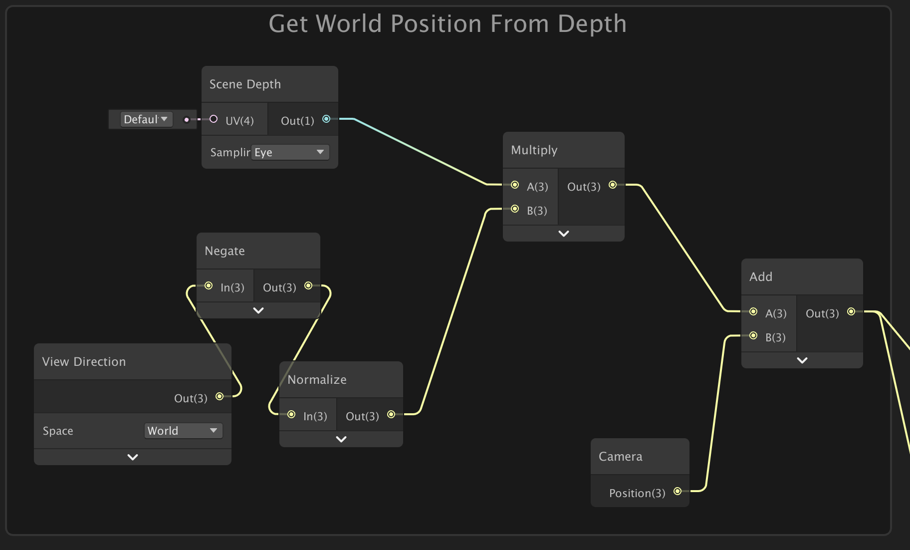
The whole graph, to reconstruct world position from depth (In an Orthographic projection) :
(This handles the reversed Z with the Branch, so it works in both OpenGL-like & Direct3D-like. The only thing that's actually needed is a One Minus node, (or switching the Near/Far planes around, but inverting the T input of the lerp works too, and is a less messy)).
The result is something like this
@devout quarry We can also do this : (The orthographic equivalent of Eye Scene Depth - Raw Screen Pos alpha in Perspective mode, that works for stuff like fog and shoreline effects).
edit : The "surface depth platform difference" could actually be replaced with a custom function node to obtain this:
UNITY_NEAR_CLIP_VALUE,
UNITY_RAW_FAR_CLIP_VALUE
);```
Then put this into the In Min Max on a Remap node. I think that makes a bit more sense to use, rather than the branch node based on Z Buffer Sign again.Result :
Hehe, glad I got this working (tested in editor, hopefully it also works in builds). 🙂
(In both graphs, the master node should be set to Transparent too).
is there any easy way to get some tessellation
I'd just like to have a little shader that i can toss a heightmap into, but i can't seem to find a way to plug in a sample texture 2d for the vertex position
ideally I'd just have a tessellation node but i don't see one
Only the Sample Texture 2D LOD node can be used in the vertex stage. Shadergraph doesn't currently support any tessellation (as far as I know).
I think HDRP has a parallax occlusion mapping node if you want to fake some depth with a heightmap though.
what should i plug into that lod node? maybe something with the camera?
im not too familiar with parallax occlusion
You probably just want to leave it at 0, it's for mip map levels of the texture.
Larger values would be sampling the smaller (and more blurred) mip map levels, assuming the texture has them enabled.
what would you say the best way to use a heightmap in the shader graph is? I'm not keen on using lots of meshes with enough vertexes for vertex position to be especially useful
@cyan I'll read this tomorrow, thanks for giving this a try!!
What heightmap are we talking about here? I assume just small offsets for surface imperfections, edges between bricks, that sort of thing?
And are you using HDRP?
yep
im a tad more used to ue4 (which isnt saying much) but that shader graph just straight up has a tesselation node
I'd probably look into that Parallax Occlusion Mapping node I mentioned then. I don't know a lot about it, but I think it does what you want
will do, thanks
@devout quarry No problem! It was great timing as I was already working on this kind of thing for a blog post. I didn't realise you could just switch to using OpenGL in the project Player settings, that helped get it working properly, so I can now work on writing it up. 😀
so theres just a node for it that outputs PixelDepthOffset and ParallaxUVs
not sure what to do with the PixelDepthOffset, its just a vector1
@halcyon hamlet I think there might be an option on the HDRP master nodes to enable a 'Depth Offset' input, which is where that would be connected to. I think it's only needed if you use the depth buffer for other effects, and want the Parallax occlusion mapping to affect it. At least that's what I understand from the docs page, I've never actually used it.
ah gotcha
ill need to hunt for that
cant figure out how to change the types of nodes at all, hdrp must be too new for many posts about it
is refraction a thing in the shader graph? I know its really easy in unreal since its just a little node thing. How would it work in unity?
Yeah you can add distortion to screen position
https://alexanderameye.github.io/simple-water I use it here (tutorial vid + shader files)
'AE TUTS' on YouTube also has some tutorial on thiq
This
would that go into albedo?
I think the HDRP lit shader also has built-in refraction, if you don't want to do it yourself.
i wish i could steal their shader and modify it in the graph
im just trying to make some nice water and the tutorial i followed basically doesnt work
Which tutorial
one by PolyToots, the effect breaks down pretty quickly and really doesn't look like water
if i have water on a shoreline i should be able to see through the shallow water, and that effect is nonexistant with that shader
thats not to say i have any clue how to do it better, but it doesnt work for my purposes
You should do depth-modulated transparency
Doesn't he do a color gradient based on depth?
those words together sound like what i was envisioning
yes but its really weird and doesnt use scene colors at all
Yeah you basically have two options imo
Either you change transparency based on depth so shallow parts are more transparent
Or you lerp between water color and scene color (grab pass) based on depth
Second option allows you to do refraction
the second one sounds closer to what he did, but he even mentioned in the tutorial that it wasnt the best way but he didnt know at the time how to do it
not that i can tell
its basically a water-colored outline that fades out
i feel like its an ok baseline
i got it to use color instead, but honestly the whole shader looks really off
something about that looks really weird to me
the depth thing doesnt work with shorelines at all either, i tested it
the addition of a shoreline breaks the illusion
even with a light to try to illuminate, you can clearly see that light doesn't properly pass through the water (though it does a tiny bit)
theres also this terrible looking reflectivity thats somehow caused by the normals, that might be my fault though
i know that because of how much nicer it looks with normal strength back at 0
most of my problem is with the way light "propagates" in the water, that is to say it doesnt really. I haven't got refraction and shining lights on the water really breaks that illusion
most of the other stuff i can fiddle with to make it look better
i have just learned that imported meshes get completely destroyed by this shader
i feel like its something to do with the mesh itself, but i'm not familiar with those kinds of quirks
plane
to spaghetti
figured it out
unity hates fbx files
obj works just fine
got a point of weirdness for my water shader
i hat mitigated it but it fails on terrain completely
when plugging in my scene color node it creates this weird halo of brightness around the coastline or object
everything else is all good but that really looks weird
Hello, is there a way to convert existing vertex fragment shaders that's in a project to UDRP or HDRP ? if so can someone link me some resources to it ? I've been googling to figure it out but It's not that easily findable.
for the life of me i cant figure out how to make my water opaque with depth while keeping a nice reflective surface
it just fades sideways and looks horrible, I'm not sure what to do
I put images to illustrate the disappearance of the transparency of my object.
I don't know why it disappears when I decrease the depth.
anyone know why ?
So far most times I get random stuff disappearing it's because of a clipping plane
Make sure nothing like that has a min of 600
Or whatever your number is
in fact I have a fog that I would rather put close but when I do my transparent object disappears on the party where there is no object behind.
Seems like the fog is starting in front of your object
yes
Maybe Unity gets confused by too many transparent materials
Did you make the material or are you just implementing it?
I do not know if making an identical shader with different options in shader graph could change the thing
i think too
I'm going through similar horrors with my water shader, desperately trying to give it depth fog. In reality I just want subsurface scattering
^^ i'm not alone xD
But my shader has done similar stuff, what's the fog material looking like?
it's a shader script
That render queue is the key I bet
It's rendering in a bad order
Set it really low or really high and see if it fixes itself
In the material try setting the render queue to different numbers
You shouldn't have to touch the actual shader
I have the impression that it is whatever happens in the foreground which is logical considering that it is on the camera, but I do not see how to isolate it
transparent objects typically don't write to depth, so whatever your shader is mustn't take that into account, or the order of operations must be wrong.
You can use the Frame Debugger (Window/Analysis) to check out when/how things are happening and that might show you what's wrong
I will see that
it's really when the fog effect arrives it makes me disappear half of the object
When I looked it up people were saying it's a limitation of the standard shader
You need to get unity to render the transparent object after the fog
That's why I'm still thinking messing with the render queue is the way to go
yes, but I don't know how to do it, I'm going to look for it
ah yeah i see
I tested all the render queues and it doesn't work
it would not be in the script that we would have to change this or add a postpross
it's possible to create 2 camera, one for my fogeffect and one other for all object ?
@strange pecan It's been a while so you might have already fixed this, but in case not : Previews don't show transparency, and your OutlineColor in the blackboard has an alpha value of 0, so is fully transparent. Edit the colour and set the A component. Shadergraph defaults colours to (0,0,0,0) so this kind of thing comes up a lot.
Cyan, which graphics API were you using to test OpenGL?
I tested it in both GLES2 and GLES3
and color space = gamma?
Yeah
Okay I'm puzzled.
So This is your graph right
To get 'scene position in world space in ortho mode'
Yeah but in your image it's just not there lol
YEah I collapsed the node
Ahh
So I subtract the scene position from the position of the object in world space
take y component etc
in my editor I get the effect as I want
but hold on let me build it
in OpenGL ES3
I get this banding effect
Ignoring the banding, is that the intended result though? What did it look like in editor?
One second I'll show
This is intended
My editor was not set to be using OpenGL ES
but this is in editor, using OpenGL ES
so roughly the same (color spaces are different between the 2 last pics so that's why colors are different)
Hmm, that is super strange. Perhaps it's some kind of precision issue?
that could be the case
Honestly I'm starting to think that's it
I'll test it again with your setup (2nd picture you shared)
copy exactly that, see what it gives on my build
What's the far plane on the camera set to, maybe that could be lowered? Not sure if the precision issues is with how the depth texture is stored or the calculations
Is it necessary to do a depth pre-pass and use the depth texture to make this effect? Can't this be a fog effect on the object's shaders?
It would be more performant, which would especially help for mobile.
I'm using the depth differences to control a lot of other effects
next I'll try reducing far plane
@regal stag thank you I will try that tonight!
Honestly I might just drop support for opengl, isn't opengl only really for older devices?
!!
😄
@devout quarry Do you need to know the depth of neighbouring pixels for these other effects?
so I guess this is indeed a precision related issue?
Hello guys i'm facing a problem with Shader graph, i'm actually doing, an Ar furniture app, and my artists send me models with all the map well setted. but in my scene the sofa That is cloth should not reflect lights like so
Honestly I don't quite understand your question @low lichen , I'm sorry
I'm using these depth differences for things like color gradients etc but also to attenuate the strength of some effects
I don't see why that couldn't be done in the object's shader itself
Do you guys know how i could change this with a setting in my shader graph so i can have controll on it ?
You can easily get the depth value of the fragment in the shader, you don't need the scene depth texture for that
You're doubling your draw calls by doing a depth pre-pass which might be unnecessary
How should I get the depth value of the fragment then?
I don't think there is a depth prepass, it's just a water surface reading scene depth texture, no?
It's indeed a water surface
But if you were, for example, doing some distortions, then you would need to be able to sample the depth of other pixels
Anyone can help me also with my problem ? 😦
But the scene depth texture is a separate texture that is rendered before everything else
I see
Alright so let's say I disable the generation of that depth texture, how exactly do I get depth in shader graph so I can use it for color gradients?
You would use the Z position of the fragment in View space
I assume you'd have to do it in the terrain shader, not the water's surface, which I think is what MentallyStable is saying.
Then you might have to convert that to linear
Yeah, the object's would be getting their own depth and doing their effects with that
Ah right because I need the z position of the 'scene' not the wate
ah
Yeah unfortunately that's not possible for this project I think
Then you can also get rid of the water plane, which reduces overdraw
The whole concept is a water shader
Is it distorting the scene?
Not on mobile no
Will it look like the screenshots you've shown so far?
So no waves on the water?
Then this just looks like a scene with fog, which can be done in the object's shader
@polar yew I'm not too sure, but if you are using a PBR shader it likely has some Smoothness / Metallic output (or Specular if using that workflow instead) which affect how reflective the material is. I think these are what you need to look into.
with object you mean the objects below water surface so to speak right
No
Yeah
Yeah I mean I guess that's true but so then I'd be changing the shaders of those objects
that's not really suited for this project
but I now understand what you are saying I think
@regal stag i already have all this kind of stuff set
Not suited because it wouldn't be possible to have custom shaders on the objects?
Yes
If you're getting good performance, then sure you can keep it this way, especially if it makes development easier.
But I still don't understand why this wouldn't be possible for any project.
as you can see i already set all the things @regal stag
@polar yew Then I'm not too sure, sorry, I don't know much about PBR shaders.
someone told me that on basic shader
it would be this
but don't find this on ShaderGraph
Like Environement Reflection should be turned off if it's cloth
any idea @regal stag anyone ?
I haven't done much with PBR shaders, you'll likely have to wait until someone else can help
You want to disable 'environment reflections'?
Looking at URP's default Lit shader, it has a checkbox to disable it. If you don't need a custom shader you could use that. (Based on your Material Property Block script you have some additional stuff though so this might not help).
Would making my own shadergraph for just a basecolor + normal map + splitting a maskmap be less costly for performance than the regular HDRP/Lit shader?
@devout quarry Here's a graph that returns the depth of the fragment
Here it is compared with Screen Position > Scene Depth:
(left: object depth shader, right: Scene Depth)
You can actually notice that the Scene Depth route doesn't maintain MSAA like the other one.
On mobile, you should try to do all effects in the object's shader, rather than post processing or pre-passes to reduce overdraw.
So anyone can give me an help with this ?
alright @low lichen thanks for that but so that shader is applied to the objects in the scene right?
The shader I'm creating will be used by other people so I want to make setup as easy as possible
Yeah, it's applied to the objects in the scene/water
I assumed since the screenshot showed all the objects as black, that they were all using the same material/shader anyway.
So the water is a transparent plane on top that uses depth to control the alpha?
Yes!
exactly, transparent plane + depth for effects like transparency
Alright, yeah that's definitely makes for an easier setup than this, but performance on mobile won't be as good as it can be.
I did one @regal stag but it's not looking good
in fact it's worse than Shader graph solution
No reflection at all
Plus i need a custom shader, as i am doing Disolve effects
@low lichen yeah, I am hitting 60fps at the moment but getting good performance on mobile is definitely harder than I thought it would be..
Anyone can help ?? 😢
@devout quarry There are some specific things that a mobile GPU can't do as well as desktop. Alpha clip can be very expensive and should be avoided.
Overdraw is a common pitfall in GPU usage, so transparent stuff is tough. And it's not about the amount of transparent objects, but how many pixels it takes up on screen.
Preferably, you'd want the GPU to only have to draw on each pixel once, but with transparent objects it has to draw the opaque first and then transparent on top.
Hmm
So what do you think is the cheapest? Having real transparency (alpha component) or 'fake' it by using the camera opaque texture and have opaque water
And thanks about alpha clip tip
Using the opaque texture would use up more GPU memory for sure and it adds a texture sample on the water, so it's hard to say. I would profile it. My gut says that opaque texture would be more expensive.
@low lichen Could you help me with my problem ? 😦
Alright will test
@polar yew You might be able to ask in other places, like the shadergraph unity forums (https://forum.unity.com/forums/shader-graph.346/). Can't say if it will be answered any quicker, but less likely for your issue to get buried in other messages.
I'm really sad
because i have to deliver my app tomorow, and well.. this is the last thing i have to do to make it looking really cool
And the fact that cloth Furnitures reflect lights like so
is ....
Even with a black Metallic map it's happening
so i don't really get why / how
What about with a black/0 metallic map and black/0 smoothness?
So, PBR material with black/0 metallic and black/0 smoothness still looks reflective ?
Yes
It's a bit hard to retrace all the discussion, but can you share a screenshot of the rendered object with this said shader, and the shadergraph ?
Yes
as you can see
the object itself
is FUCKING SHINNY
when it should not
Full black map for Smoothness and metallic
The preview might not be the best way to visualize this, how is it looking in a scene.
This is not "shiny", it's the fresnel effect
It's looking exactly the same as in scene @amber saffron
i'm sending this because it's the same
So do you have any idea how to remove this on cloth and keep this effect on the metal parts ?
Have a float property, set it to 0 when you don't want fresnel, 1 when you do. Multiply it with the fresnel result
With the metallic ?
When I said fresnel, I had in ming the natural fresnel effect that material have in physicaly based rendering
Can you show a screen of what it look like if you disconnect metal, smoothness and occlusion, and set them to 0,0,1 ?
Even if you put the power to 0, the output won't be 0. x^0 = 1
+1 for the fresnel node power : power here is the "curve" of the fresnel, not it's intensity
i mean it's still reflecting
Make a new float property like I said before, multiply it with the fresnel output.
You can controll the intensity my multiplying the result of the fresnel node by a constant
0 beeing no fresnel
i'm not actually super good with shaders, where do i get the fresnel output
the output of your Fresnel Effect node
That's the connection that goes out of the fresnel node
left of the node : inputs, right : outputs
Yes, but use a new Vector1 property as the B input, named like "Fresnel Intensity" or something.
It's doing weird stuff
When you want the Fresnel, set that property to 1. For the cloth / when you don't want the fresnel, set it to 0.
What do you mean by "weird stuff"
Where is the output of the second multiply node connected to ?
connected to albdeo
oh, so you are multiplying the albedo by the fresnel
That's weird
Hum
Then why did it look weird in the first place... wouldn't the fresnel power set to 0 cause the output to be 1.
I'd suggest trying to isolate further : don't do fresnel and connect directly the albedo texture sample to the albedo input of the master node, and see if it still does "reflect"
What's in "emission" ?
as this is a shader that does Disolve and Insolve
output of top multiply
Is going to emission
perhaps remove the emission input for now, see if it makes a difference
I need to go, I'll be back later on, hopy Cyan can help. Else, if you can share the project or object+textures+shader I might be able to look at it ?
I need to go back to these texture samples. To me those metallic/smoothness textures don't look fully black (0) to me
Are you sure, because when I eyedropper the preview it's not. Unless the screenshot has been affected somehow
You don't have to assign a texture btw, you could set the default texture value (/"Mode") to black in the blackboard
Okay.. I'd probably still set the texture to empty and change the "Mode" to black in the property blackboard, just to be on the safe side. If that still doesn't help, Maybe you need to remove all the inputs on the master node and connect them one by one to see at which point the weird reflections happen. I have to go for a little bit.
But
I did it
It seems it doesn't come from the shader
I mean, all the stuff that i have doesn't impact it
the only way i found to "hack it"
is by increasing like crazy the contrast
on the smoothness
contrast power = 0
Contrast power = 7
but like this, the feets are looking bad
😦
Like I said : do you mind sharing this stuff ?
The shader ?
shader texture object
I can send it to you for sure if you want to try stuff with it, but unfortunately i will not be able to send the project... as it's for a client, and my boss will not be ok about it haha
You can eventually isolate the object in a scene and use export as package feature
i'll do that right now
It should automatically select the proper assets for exporting
yeah yeah i know
Hum ...
when i try to export scene
it's selecting all my project into dependencies ....
oh, bad ...
Hi everyone, what is the correct setup for an AO map in unity ? Did I need to pout it in single channel (Red or Alpha) ? let it in default ?
I think AO was part of that "Mask Map" that Unity does
I believe it's the Green channel
It's just a grey scale texture otherwise
I'm using a distortion shader in shader graph that uses the Scene Color node - but it's too low quality for what I'm interested in
There are jagged edges along objects that are distorted by the shader. Any way of using anti aliasing or getting a better quality sample?
Scene Color HD node if you're in hdrp
I'm using Universal RP, unfortunately
In URP there should be a downsampling option on the pipeline setting asset. If you want better quality make sure it isn't doing any downsampling. You might need to use some post processing based anti-aliasing if there are jagged edges (it'll be on the Camera).
Where is this pipeline setting asset?
Yeah I know but I create a shader who give me the possibility to add and other AO. So I have an aternal AO map. I just want to properly configurate it
Cool, the downsampling setting was causing it
@halcyon hamlet It's the asset which defines the pipeline. It would have been created somewhere in project files and set in the "Scriptable Render Pipeline Settings" box under the Graphics window of Project Settings. (It's also different for each pipeline. I'm not sure what the HDRP one looks like, but I assume it also has one. It likely won't have the same downsampling options for Scene Color as URP, as HDRP has multiple mip map levels anyway.)
@ocean wren Unless you want to pack more informations in this texture for optimization purpose, importing it as single channel is enough
@amber saffron Okay ! doesn't matter to put it in red ou in alpha, it's the same ?
apart from what channel you'll need to use, no big difference 😄
Okay, perfect ! thanks 🙂
totally missed this before: https://github.com/Unity-Technologies/ScriptableRenderPipeline/pull/4940
GitHub
Purpose of this PR
This PR is a near total overhaul of the API for shader generation. Per-pipeline, per-master SubShaders are replaced with static definitions for SubShader, Pass, Struct, RenderSta...
it bumps the importer so if you're using the SRP repo, expect a long reimport the first time you launch projects after that merge c:
I often wipe the library before testing new stuff so it pretty much imports everything again anyway 🙂
im desperately trying to do refraction on my water but i cant find anything on it
im assuming its something that ill need to plug into my Scene Color UV node
The default input of the Scene Color node is the Screen Position node. For refraction you'll likely want to offset that screen position slightly, perhaps based on some noise * a strength of 0.01.
how would i go about offsetting it?
By offset I mean use an Add or Subtract node
ah ok, my brain usually thinks of that Tiling and Offset node
That would work too, The Tiling and Offset node is equal to UV*Tiling + Offset, if I remember correctly.
If I don't need both tiling and offset I usually just use a multiply or add, but it's up to you
only uses vector2 tho
That's true. Not sure if the scene color requires the ZW components or not.
works like a charm, thanks so much
my problem now is the weird artifacts on the side
You might need to remap the noise to a -1 to 1 range, instead of a 0 to 1 too btw.
That might help solve those artifacts
Either use a remap node, (or Subtract 0.5 would remap it to a -0.5 to 0.5 range which would be good enough)
im gonna call this a step in the right direction
id prob use remap
minor problemo
also get this weird banding on the side
its mitigated by turning down the values a bit
I think that's the colour texture clamping due to offsetting the screen position outside of the screen's range.
Might be a way to check if the offset pushes the screen position outside the range of the screen, and when it does multiply the offset by 0.
I guess the Screen Position is in a range of 0 to 1, so if the offset position is smaller than 0 or larger than 1 for both the X and Y axises would be outside the range?
i need to like feather the edges so it doesnt break
and ideally cut off rendering objects above the material plane
like the top of the cube refracting when its not actually behind the material
it breaks the illusion severely at a distance
Yeah, that part is a little harder to fix
I have a question: how come Unity terrain doesn't have tessellation? Isn't it useless without variable level of detail in the distance? Or does it avoid rendering the whole plane with very dense tris some other way?
@halcyon hamlet You may be interested in this. It's a breakdown of a water shader I made a while ago. It compares the depth to prevent objects above the surface being refracted too. It's not a perfect solution but might be a good starting point. https://cyangamedev.wordpress.com/2019/06/10/water-shader-breakdown/
(The refraction part is also based off this which you might find useful, but it's for built-in not shadergraph : https://catlikecoding.com/unity/tutorials/flow/looking-through-water/)
i found that one yesterday and planned on reading it today, lol
ok i really dont understand this article
brain too small
mainly this bit
The screen position is simply the clip space position, with the range of its XY components changed from −1–1 to 0–1. Besides that, the orientation of the Y component might be changed, depending on the target platform. It is a four-component vector because we're dealing with homogeneous coordinates. As explained in Rendering 7, Shadows, we have to divide XY by W to get the final depth texture coordinates. Do this in ColorBelowWater.
Clip space means the position relative to the camera. So (0,0,0) would be the position of the camera and (0,0,1) would be 1 unit in front of the camera.
that four component vector is throwing me
what is W
ah apparently the node does that part for me by default
Does anyone know the arts of shadergraph
what question do you have @grand jolt
I'm trying to make an outline for a sprite, but my attempt on it fails on step one already. I wanted to add a outline on the left side first, but it goes on top of it like this, and it shifts weird (these whites on the left are the outlines) :
my graph looks like that
so the problem is that i dont know why it happens, theoretically it looks good for me
if I make thickness bigger then the distortion is even more drastic
basically youre rendering two things, one on top of the other
but you're offsetting it in one direction so it shows up on one side
oh, so how do I like literally add it, rather than place on top of it
if you know what im trying to say
in the tiling and offset play with the UVs if youd like it to be all around
or the tiling
what are these UVs
in that Tiling and Offset node youve got UV, tiling, and offset
you can make it tile less to kinda scale it up
or you can do a similar thing with the UVs
so if you tile it at numbers less than 1, you kinda scale up the thing
so it'll make an outline for you
rip
remember to remove the offset so it scales around the center
ok i figured something out but the colors are rigged. the white works fine, but if i set it to black for example it takes the color of the sprite itself, other colors are a bit weird as well.
the second image is black
Is it because it's unlit?
@regal stag i merged your water shader into mine and it works great, last step is that depth fog. I'd prefer to be able to go underwater, but this has already been such an ordeal getting the surface done idk
how does add exactly work? seems to mess up with colors
@halcyon hamlet Yeah, if you want the camera to be able to go underwater that would likely have to include a post processing / image effect. It's not something I've looked into
the caustics kinda broke, but they werent working so well in hdrp to begin with
@grand jolt Colours are just 4 floating point values (numbers). If you add two colours it just adds those components. e.g. Red(1,0,0,1) + White (1,1,1,1) = (2,1,1,1)
If you add Black (0,0,0,0) to another colour, it won't change.
You probably need to use a Lerp. A as the base colour (texture sample?), B as a Color property / Color node, and T as a mask controlling where the outlines are.
I followed codemonkey's guide step by step and still it ended up different
Ima try this lerp
any idea why my water still ends up this really weird orange color in one direction?
all i know is that its linked to my normals somehow, but i need those for detai;
its probably a lighting thing but idk how to fix it
oh its linked to my sky
i guess physically based sky isnt the best way to go rn
i do want a sun in my sky though so I'm not sure what the intended solution is
Yay lerp worked. Don't know why the method that I followed worked in tutotrial and not for me. Thanks!
How can I make it so the _maintex is taken automatically from the sprite renderer the material is used on rather than setting it manually?
If the property Reference (not just the name) in the blackboard is set to "_MainTex" it should use the sprite from the SpriteRenderer automatically.
Oh
Having trouble trying to apply a custom material/shader to a character that uses the Skinned Mesh Renderer without changing the existing materials. My understanding is the renderer maps the materials list indexes to the textures, and just adding my custom material to the list isn't behaving as expected. Is there a general strategy for applying a custom shader on top of a character model setup?
The goal is a visual effect (dissolve, transparency, etc). Not sure if it's supposed to be a postprocessing layer or attached to the camera with some kind of filter or what exactly is best for this specific renderer
@static apex Not sure what you mean by mapping the materials list indexes to the textures. What textures are you talking about there?
On the character. It's a rigged character model, which has materials and textures. I first tried just adding my custom shader/material to the list, and it changes how the base materials render. Looking at how the Skinned Mesh Renderer works, it appears to use the material list indexes as references from the texture mapping
So I'm trying to understand how with an existing model having textures/materials setup, you should add some effect overlay shader to it and only it.
All the guides I can find demonstrate with a blank regular mesh object and just attach the single new custom material