
#archived-shaders
1 messages · Page 139 of 1
anyone here is a shader programmer maybe?
Atm i have done some basic vertex snap via world space
but totaly cant go into affine texture mapping
would be glad is someone could help with the affine texture mapping into shader graph
this is what i want to atieve
@urban oxide Here you can see a shader that is modifying the UV in the vertex shader so it reverses the perspective correction done normally
https://github.com/dsoft20/psx_retroshader/blob/d6754070390529d0b50c3b3bef3d087e731e9e45/Assets/Shaders/psx-unlit.shader#L48
GitHub
Shader that "emulates" the rendering style of ps1. Contribute to dsoft20/psx_retroshader development by creating an account on GitHub.
You want help converting this to nodes in Shader Graph?
yes, the thing is that im not a programmer, but a 3d enviroment / prop artist
i somehow can read the code tho
but i feel a lot better in visual scripting because of using software such substance designer for example
Well the first line float4 affinePos = vertex;//vertex; is assigning affinePos, but then it's never used, so I guess the person that wrote this just forgot about it, so we can ignore that line
The second line o.uv_MainTex = TRANSFORM_TEX(v.texcoord, _MainTex); is a standard line. It's just taking the UV coordinate from the vertex and transforming it so it has the tiling and offset that is applied for the _MainTex
Probably whatever default node used for getting UV is doing this already
the 3rd and 4th line is using the alpha channel of ambient in lighting section
as a input parameter
That's a little strange
i guess he needed some kind of param / verctor 1 to handle the normal distance distortion
whats the "vertex.w" thing?
i see that he is using the one only input diffuse texture (_MainTex) and then adds "vertex.w" multiplied by lightmodel ambient alpha channel to distance
then dividing this by distance and dividing this by 2
affine texture mapping doesn't do the perspective divide...it's linear across the endpoints. As I understand it.
The .w component is the perspective divisor.
Apparently, the only thing that is necessary is to divide by the vertex's w. Not sure what everything else in that shader is for.
Might be a fog thing or something
https://en.wikipedia.org/wiki/Texture_mapping#Affine_texture_mapping
there's a formula therein for affine uv's using screen-space sizes. I didn't look at the shader, but I assume he also had screen-space locations? Or maybe could just "undivide" the perspective.
Texture mapping is a method for defining high frequency detail, surface texture, or color information on a computer-generated graphic or 3D model. The original technique was pioneered by Edwin Catmull in 1974.Texture mapping originally referred to diffuse mapping, a method tha...
@urban oxide It seems it's not trivial to get the full Vector4 with the w component in Shader Graph
The Position node just returns Vector3
hmm this is a bit hard for me to understand this wikipedia article 😄 but im trying to figure as much as possible
right now i have got only the vertex snap
i guess that the affine texture mapping should go to the vertex normal in master material?
No, you're just interested in modifying the UV before sampling whatever texture you want
You have to do this in the vertex stage
aah
The problem is that there doesn't appear to be any way to get the object's clip position with the w component. The Position node just returns Vector3, probably because most use-cases only require a Vector3.
So you might have to create a custom node just to get that
found something like this
oh nooo 😦
thinking about making something custom makes me scaryy haha D:
this thing what im trying to do is enough custom for me!
Think of it as an opportunity to learn something new
I've never written a custom node for Shader Graph, but I'm willing to learn with you.
hm this ue4 graph
im wondering this
this is a custom thing?
aah no
i must search for it then
ue is having this node
😄
@urban oxide Okay, here's something
https://forum.unity.com/threads/what-is-the-equivalent-of-unityobjecttoclippos-inside-shader-graph.809778/

Unity Forum
Hi, I'm pretty new with shaders and started to look more into them in Shader Graph, and trying to convert from a script shader is not resulting on the...
@urban oxide If you do those nodes, you'll end up with a Vector4 and the w component you want.
omg man how did you found this? 😄

I could be wrong but I think the w/a component of the Screen Position node set to Raw would also be the clip space w pos. 🤔
IIRC it's a depth but it might convert to, or end up being the same as, perspective divide. Then I'd have to dust the fog off dept storage format...to know if it varied at that point in the pipeline.
this is hard as f to understand you guys but also really challenging! 😄
as i said im a totally newbie to shader scripting 😄
but im trying my best 😄
o.uv_MainTex = distance + (vertex.w(UNITY_LIGHTMODEL_AMBIENT.a * 8)) / distance / 2;
now i must to viscual script this line
when we have the "vertex.w" thing
lol. I guess it's both a depth and a perspective divide!
See post 7 here by boglus.
https://forum.unity.com/threads/what-is-screenpos-w.616003/

Unity Forum
I'm a noobie at shader programming and am trying to learn to create intersect highlight effect. but I can't understand some of the concepts and...
@urban oxide Have you tried the shaders in the repository you linked?
yes i did
Do you want the exact same affine texturing?
yes i guess, i want to replicate the ps1 shaders
dont mind to use the same script i linked
but i guess ps1 used the ones and only rendering components as we speak about these now
guys
the only thing i changed in the code script yesterday was
"unity_lightmodel_ambient.a" because its no more supporting the alpha channel in lighting ambient
i remember i swithed to another variable
and used the "unity_ambientequator.r" for the "affine texturing" slider
and it started to work
and this is my yesterday project
@meager pelican Thanks so much for the support yesterday. Fixed it. So it was just a case of multiplying the normal by x1 ,y-1 , z1, w1 ? I thought I needed to flip the green channel but if I understand correctly this multiply here was just flipping the entire normal's verticals? If I wanted to invert the green, in that case you DO you invert colors and invert the green before using combine to rebuild the normal.
Anybody have any suggestions on how to accomplish a UI Blur effect in HDRP? I want to blur everything behind the UI element with blur material. Plenty of resources on legacy, but not HDRP.
camera stacking or some shit IDK I glossed over it somewhere
Thanks so much for the support yesterday. Fixed it. So it was just a case of multiplying the normal by x1 ,y-1 , z1, w1 ? I thought I needed to flip the green channel but if I understand correctly this multiply here was just flipping the entire normal's verticals? If I wanted to invert the green, in that case you DO you invert colors and invert the green before using combine to rebuild the normal.
@shell walrus
I'm not sure I understand you, but the output you get from the Texture 2D sample set to NORMAL mode is an UNPACKED normal component results in the range of -1 to 1, as I understand it. Some normal maps are inverted when they come in from whatever tool and have to be flipped. The best way is to fix it at the source/texture level, but you can flip it yourself by negating the green channel. Which is NOT the same as using the color inversion. The color invert will use 1-c, and the negation will take c and make it -c. Basically 0 - c.
So it all depends on what you're doing and what your input data is and when you do it before unpacking or not.
Now for a packed normal ON SOME IMPLEMENTATIONS (unity uses two different methods) you can color-flip the green channel, but I don't think that's going to be very portable. Basically one implementation packs -1 to 1 into a 0-1 value, so you can invert that and THEN unpack it and you'll end up with the flipped value. But regardless you have to plug the UNPACKED values into the master node.
(All with full grains of salt)
Wow. 😉
Glad you got it working!
hi, i'm haveing an issue with shader graph. i want the group "vert function" to be in the shaders vert function but since it's connected to the albedo it's added to the frag. is there some way to go around this and have it be in vert and have it pass the connection leaveing the group to frag through a variable the same way you could when you wrote the shader yourself?
@proven stirrup Someone else (?Cyan?) mentioned you can use depth of field post processing to simulate a blur.
@wicked stream Is there anything in that custom function node that makes it be in frag?
@meager pelican no, there's nothing special in them. they are merely a way to cut down on the node count. i'll give you a picture. gimme a sec...
It's only the "red one" I'm asking about.
That's interesting.... So you're passing some kind of color in and trying to store some vertexID, which will get interpolated.
Sec...
It all ended up in frag()?
seemes that way... when i try pluging it directly into frag it doesn't interpolate as it should. it interpolates as if it ran it in frag...
here's the raw color data of a test mesh
and here's what it's doing...
lol.
yeah... it all goes red... as it would if it had even the slightest bit of red as it would have if it took the color in frag
IDK if you can access vertID in the shader or not with a custom node. Doesn't look like it. And IDK why they didn't add one.
I suppose if push comes to shove, you can just edit the shader source and "own" it from there. You can right click on the master node and "view generated source" or some such.
The only reason you're doing this is to stuff vertID into colors because you can't access it natively, right?
yeah... the purpose of the shader is to make it so that each vertex has a "texture id" it can use to pull a texture from a atlas texture and then blend between each vertexes textures.
i had it working just fine in older versons of unity but it needs to be remade for URP
What you can do is stuff extra data into various UV channels or colors rather than a separate texture.
But that may not be what you want. And it makes each mesh custom and you'd lose instancing.
But you could access it.
If you need it per pixel...oy.
the whole issue is that i need to give each vertex a value and then keep the value intact in the frag so that i can use it to find the atlas texture each vertex is refering to... i need this in the vert to help undo the interpolation in the frag
That sounds to me like saying "I want to set the UV.s in the vert, as defined by some data I look up and calc with, and I still need UV's interpolated for texture mapping". BUT IDK if I hear you properly.
Are you maybe using a different texture per pixel depending???????
Wouldn't one triangle be referencing one atlas (with whatever uvs)?
it may be easyer for me to explain it by showing the old working version shader
void vert(inout appdata v, out Input o) {

    UNITY_INITIALIZE_OUTPUT(Input, o);
    o.atlasId = v.color;

    o.vertexId =
        o.atlasId.r > 0 ?
        float3(1, 0, 0) : //if vert0
        o.atlasId.g > 0 ?
        float3(0, 1, 0) : //if vert1
        float3(0, 0, 1);  //if vert2
}

void surf(Input IN, inout SurfaceOutput o) {
    float3 id = IN.atlasId / IN.vertexId + _Bias;

    float3 u;
    float3 v = modf((id * _AtlasSize * _AtlasSize - 1) / _AtlasSize, u);
    u = u / _AtlasSize;

    float2 uv0 = float2(u.r, v.r) + IN.uv_MainTex;
    float2 uv1 = float2(u.g, v.g) + IN.uv_MainTex;
    float2 uv2 = float2(u.b, v.b) + IN.uv_MainTex;

    o.Albedo = mul(IN.vertexId, fixed4x4(
        tex2D(_MainTex, uv0),
        tex2D(_MainTex, uv1),
        tex2D(_MainTex, uv2),
        fixed4(0, 0, 0, 0)
    ));
}
Huh. u looks uninitialized.
But OK. I thought you'd have used:
uint id : SV_VertexID;
in your vert input struct. That's what I thought you were doing.
is there such a thing?
but yeah, it would be interpolated.
Yes, that's unity code. The SV_VetexID is a semantic that gets you the vert ID for the triangle.
But IDK that such is available in SG
i haven't seen SV_VertexID before but as you say it seems it doesn't change much as it would be interpolated...
Yeah, but you're assigning that in the vertex color instead, right?
yeah...
So you should just be able to interpolate that color. So you don't need the vertex ID. You need the vertex color (which you've pre mapped to the id).
You CAN do vertex colors with SG! 🙂
If I'm following you.
And your vet colors are set on the mesh to map the red/green/blue of the verts, and would show that color in that first image you showed me (the correct one). Right?
What's IN.vertexID on your input struct? from the sample surface shader code.
Nevermind, I see it.
I guess what I'm asking is what's different from vertex color and the calculated vertexID?
Gimme 3 data samples (one triangle). What's the vert colors now?
lets say se have a triangle tri in the mesh
i could represent it's color by someting like ```
tri: {
vert0: {0.1, 0, 0}, //this would be the rgb
vert1: {0, 0.3, 0}, //this would be the rgb
vert2: {0, 0, 0.5} //this would be the rgb
}
the vert function would then set "vertexId" to ```
tri: {
vert0: {1, 0, 0}, //this would be the rgb
vert1: {0, 1, 0}, //this would be the rgb
vert2: {0, 0, 1} //this would be the rgb
}
<delete><delete><delete> ;)
Sec. I'm thinking vert colors are float 4....
I think you can just stuff the vert ID into the alpha if you want to support different RGB values for whatever other reason. When you generate the mesh (or update it in C#) you can set the alpha to the vert id if you want to pass it.
Anyway, I'm pretty sure the vertcolor node will remain in the vert function. The other one....yeah.
You're getting degree of red/blue/green pass interpolated...
if all vertexes store their value in the alpha channel how am i supposed to separate them again?
Depends on if you actually want vertID or not. Doesn't look like you do. You want to smear RGB around the triangle.
no, the vertex color represents the ids in the atlas. smearing it about would interpolate the ids. the thing to interpolate is the textures in the atlas those ids refer to
OK you did this in your code:
    o.atlasId = v.color;

    o.vertexId =
        o.atlasId.r > 0 ?
        float3(1, 0, 0) : //if vert0
        o.atlasId.g > 0 ?
        float3(0, 1, 0) : //if vert1
        float3(0, 0, 1);  //if vert2
That will set the verts as shown for each vertID. But the results in the frag will look smeared, because o.vertexID is interpolated.
So somewhere in the middle of the tri, the IN.vertex ID will look like (.5, .5, .5) smearing between 0 and 1 in the frag.
yes but if you look in frag i recover the original c.color by divideing the o.atlasId on the o.vertexId
I guess that's where you're confusing me because there's THREE original colors, and one pixel interpolated result. So what color do you recover? (I'll have to go look back again...sec)
ok... let's see if i can explain. each triangle has three vertexes
each vertex stores one value
Yeah, like these:
i could represent it's color by someting like

tri: {
vert0: {0.1, 0, 0}, //this would be the rgb
vert1: {0, 0.3, 0}, //this would be the rgb
vert2: {0, 0, 0.5}  //this would be the rgb
}```the value is stored as ONE float in ONE of the vertex color channels
when they then get interpolated...
the atlasId/vertex color could be something like {0.1, 0.5, 0.2}
BUT i also send the "vertexId" to the frag and that also gets interpolated...
since vertexId is 1 in the channel that had data and 0 in all others ({0, 0.22, 0} would become {0, 1, 0})
it acts as a percetage for how much of the atlasId is left for any given vertex
So far. But then you divide atlas id by vert id and add a bias.
yes...
giving you.....
by divideing any given interpolated value by how many percent of it's original value remains i recover the original
There's THREE "originals". Either that or you could just have passed the same value 3 times and skipped all the math n stuff.
What's "the original value" to you?
say that in frag i have the atlasid {0.1, 0.5, 0.3} and a vertexId of {0.2, 0.5, 0.3}. by divdeing them on oneanother i get {0.5, 1, 1}. this mean vertex0 had a value of 0.5, vertex1 a value of 1 and vertex2 a value of 1
Yeah.. lol I can read em. ;)
But what did you pass IN? why?
What does (.5, 1, 1) result mean to you in the frag()?
I think what he is getting at is the (.5, 1, 1) is the result of the interpolated vertexID
Sure.
But that could be done by just setting the vertex colors as the 1's and 0's for rgb. So I guess he needs the "other values" too?
I'm finding it a little difficult to follow, but I think anything like this in shadergraph is going to be difficult as there isn't control over what data is passed between the vertex and fragment stages.
Agreed.
seems that way
I suggest either finding a different way to pass the data in, or copy the generated code on the master node and make additions to support what you are trying to achieve
well, though not the wanted outcome. i suppose it can't be helped...
I don't think you need to "recover" anything that way. It doesn't make much sense to me in a surface shader either, to be honest. But maybe it's just me being dense.
you can get the RGB smearing from the vert colors. BUT if you need two sets of vert colors, that's why you want vert ID. Or something.
You're abstracting something into a spritesheet index lookup or something.
The (.1, .3., .5) seems like what you really want to pass around.
Not (.1, 0, 0), (0, .3, 0), (0,0,.5)
the (.5, 1, 1) is the ids to use when getting the texture from the texture atlas (i.e vert0 has 0.5 as in of we had a 4x4 texture atlas: 0.5 * (4 * 4) = texture id 8. then we do a bit of modulus and such to get that ids uv. in this case (0.75, 0.5). look at the code above if you wanna see how that math works)
I guess the question is could you not just pass the uvs required in, rather than using vertex colours to encode them?
no, if i pass in the atlas ids uv directly. then they interpolate and if i where to counteract that i'd need to do what i'm currently doing with just the id only on both a u and a v component. besides, that would also require 3 separate uvs to work. it's just better in every way to use a id
normally, you shouldn't have to "undo" interpolation....if you're passing a constant value, you pass that. And if you want to pass the %r, %g, %b through, you pass that as an additional thing and let it be interpolated.
You're un-interpolating. Or something.
yes. exactly right.
thing is, i kinda need to as the thing i'm passing is per vertex and when the data is on the vertex it get interpolated. so yeah...
anyways though... i think we're not getting anywhere at this point so maybe i just take the blow and edit the generated code...
i thank you both for your time. especally you @meager pelican considering we've been dissuccing for more than a hour and a half now XD
Hey man, I'm sorry I couldn't help ya more. Maybe let us know how you come out, huh? I wish you peace and fun...not frustration. Thanks for trying to explain.
no problem. i actually had kinda fun XD
I still think you can probably find a different way, but ... well, have fun first off. 🙂
sure, i'll friend ya and i can get back to ya with how it went 🙂
@meager pelican thank you for the tip. So you're saying this would be a Volume set to local on the UI gameobject? Does volumes work with UI components?
I mean, I understand how I would use Depth of Field to blur everything, but I was mostly interested in only blurring the background behind designated UI panel/images. In the legacy system, it was just a matter of assigning a special material with a blur shader to the Image, but I'm not sure how to pull off the same thing in HDRP
I'm thinking the DOF would work on the background, not the UI. I thought that's what you wanted.
But you want the UI panel to be see-thru blurry. I see. Sorry. Maybe use an texture to distort the UI material. There is an opaque pass that SG can use instead of a grabpass, but it won't have the transparent layers in it. You could perturb multi-sample and average the uv's of the opaque pass to fake a cheap one-pass blur.
Make sure the camera/graph settings have the opaque texture active (I think it's also in HDRP...that was what you used, right?). Double check first. I know it's in URP and I'm thinking it's in both new pipelines.
It's a scene-color node in SG.
Thank you for your time @meager pelican. I read somewhere that opaque texture wasn't available in HDRP, but I could be wrong about that. I think I need to do a little more digging. Honestly, the full screen blur wouldn't be too bad, just not my ideal user experience.
Yeah, and with all the post processing in HDRP, I'm surprised you can't get at something from the scene. But maybe not.
New stuff, eh? 😉
@proven stirrup good news. This: https://docs.unity3d.com/Packages/com.unity.shadergraph@7.2/manual/Scene-Color-Node.html
says it is supported in both, but the opaque texture technique might be specific to URP. But anyway, I'd try that node and see what you get and then screw with it to blur stuff.
you rock! I'll check that out
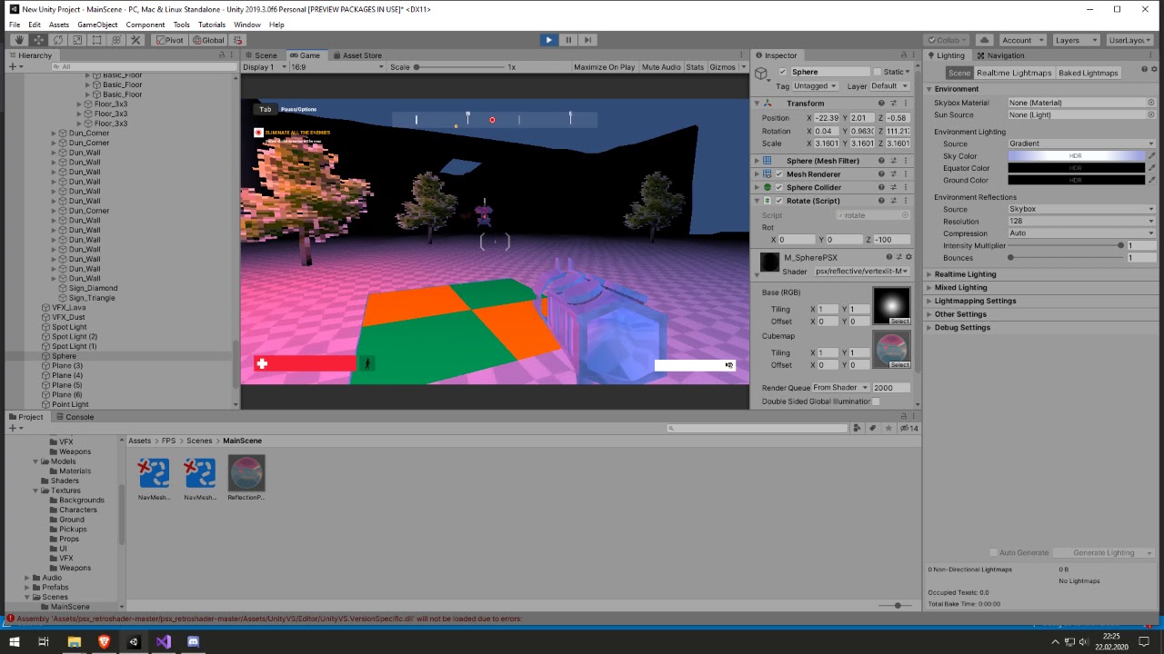
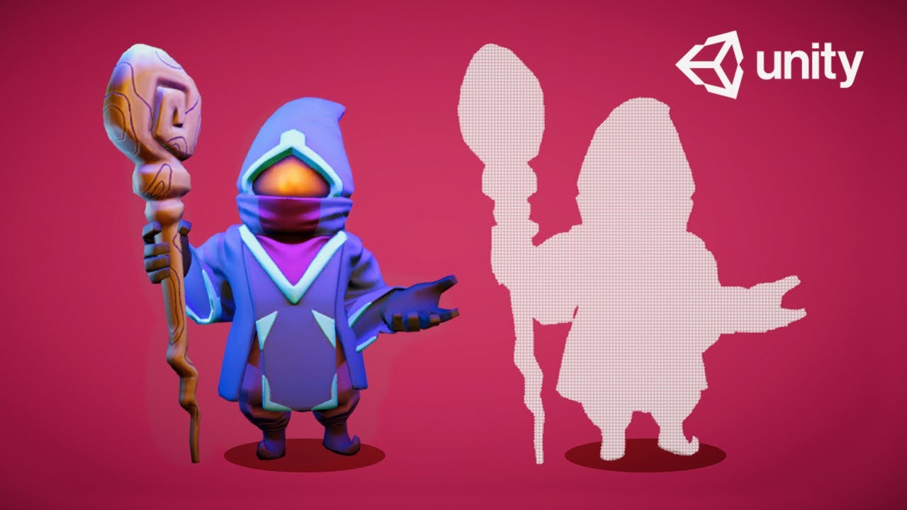
Hi all. Trying to produce something interesting, I want to create a grayscale world but the player would have a sphere field around him that colorizes the area around him. When an area is complete, the entire area would become vivid again. I do have a grayscale shader, that I can add to objects and can swap the material in runtime if needed; however, the forcefield that colorizes the area around the player has me stumped since even if I can adjust the color of the items inside the sphere, I would not have the information as to which colors to swap to. Other option would be to this via the camera but I am still stumped on that as well.
would a 3d shader graph like this: https://www.youtube.com/watch?v=hTJqo1HeEOs
work in a 2d game?

Unity Shader Graph - Shield Effect & Impact Detection Tutorial
In this Shader Graph tutorial we are going to see the steps I took to create an awesome Shield effect that detects hit collisions. The impact detection is done with a script that controls a property of a Sphere Ma...
@little abyss Do you know Beatrate? ;)
is the field visible or is it just a distance/radius calc to some player-specific postion?
What you do is color everything, but if it is outside the sphere and not an "all on" you grey-scale the color. So you DO have the color information, because that's what you convert to B&W. 😉
P.S. What pipeline are you working in?
What a great idea, somebody should make that 😂
I actually go it. I used this guys guide https://www.youtube.com/watch?v=KQGNMCwJaNQ stripped out his bloom and other effects due to time constraints, and modifiy the grayscale mesh using MaterialPropertyBlock() with an ontriggerstay (checks if the mesh has the grayscale shader) with the radius and center position of my trigger volume. Its perfect!
Final part of the tutorial series on how to create a spherical mask shader in CG language, within the Unity Engine.
Created by Peter Olthof from Peer Play.
Support me in creating tutorials by becoming a patron on my Patreon and get access to the full source code of all tutor...
*modified.
His system used a global variable but I localized it usig the MaterialPropertyBlock feature so I can make more than one area 'colorized'/
now I am debating on dynamically creating the grayscale meshes, adding them to a list, (dont generate another one if it already exists) and swap them at rutime so I don't have to make a bunch of grayscale meshes for 1 level lol
I can get the color and texture of the original item and just generate a mesh using that.
worried about speed/ram constraints though.
@little abyss it was an in joke cause I implemented this after bugging this chat for a while recently 😄

I essentially just pass an array of sphere positions and radiuses into shader and check distance to any of them in pixel shader. If any of spheres cover the fragment t is 1 else 0. Generate b&w of initial color(small function in shader, no additional textures necessary), then lerp between original color and greyscale using that t.
If you don't need partial coverage, you can just overlapspherecast from each sphere and set a cover flag on objects. Then the shader would just use that flag for t instead of doing position checks of its own.
@grand jolt i'm looking for something like this like for a year
im start learning shader today to create this effect on a game i want
Well, good luck to you 😄 Should take you less than a month to get used to shaders.
i now start understand uv world space.
i'll save this videos of yours, thanks for give some tips on how to to it.
Let's race who releases a game using that effect on itch.io first ayy lmao.
Kidding, I still didn't come up with a use for it.
kkkk
i have a use for it already
but since the artist i was working don't have idea of how to build shader
i step a little from gameplay programming to create the shader
that's why i was looking for this and learning basic of shader
That looks cool @grand jolt :)
Now I see how you wanted the skybox part.
Did you also want flag-shading on the unlit stuff, or just greyscale?
You've seen this already haha.
Back then I wanted partial coverage cause the floor gotta get the colors too.
Now it's just a faint memory in a git repo history.
@grand jolt thanks. i'll now add it to a PBR and after that i'll try on 2D shader
Yup! mine works fantastically. I actually did use the dynamic texture generator. for each material on the mesh, I check if it is the Grayscale shader, if not, it calls a script that I use to create a shader mesh with all the identical properties of the original mesh (texture, color, tile status, metallic, smoothness, if it supports it etc) and store that fabricated material in an array with Name+_BW, if a material with my script tries to make a new material, it checks the list first and if it finds it, just swaps it.
I have both a Player colorizer sphere and a master one.. Both can work independently.
well master overrides the player one, but since the area will colorize from where the player is, it creates a nice effect.
I need to add additional functionality to the shader piece by piece. Added support for bump maps, need to add UV support etc.
https://i.imgur.com/oMiQZbi.gifv when i change blendshape values my lighting changes?
the issue is independent of which shader im using
oh
i turned normals to calculate in the import settings
fixed it
it was on import
so.. @little abyss when you gonna teach us the secret?
amazing work @lavish stream
what was the import problem?
would someone like to help me with shaders for particle effects on a render texture from what i see on google you just need to add "ColorMask RGBA" but i cant seem to get that to work.. my shader knowledge is very limited.
@wicked stream I was thinking on this, because it bugged me.
You're un-interpolating...meaning you're "recovering" the original color. And you're fudging around the colors to "tell" what vertex you have, and recombining this into some effective color.
I'm just not 100% on what IN.atlasID is going to look like or why you're doing it that way.
I would think you could put the vertex ID in the alpha of the vert color, and then let the RGB be the same for the triangle, so you don't have to "recover" it.
You'd still do your if's in the vert function though...so if SG won't let you put it there you'll have to edit the generated source code.
Let's say the triangle had a color value in your indexing scheme of {0.1, 0.5, 0.2} (your example) you would set the vert colors to be {0.1, 0.5, 0.2, 0}, {0.1, 0.5, 0.2, 1} and {0.1, 0.5, 0.2, 2} so the alpha value had the vert ID that your vert() function needs to generate ANOTHER value (o.vertexID) that gets interpolated like you have with your if's.
So you'd set:
o.atlastId = v.color.rgb; // .rgb assume float3

o.vertexId = float3(1, 0, 0); // vert 0 default
o.vertexId = (v.color.a == 1) float3(0, 1, 0): (v.color.a == 2) float3(0, 0, 1) : o.vetexId.
So then you don't have to "recover" anything....
I think. The hardware should interpolate for you, or not. The color RGB value won't change and keeps your indexing scheme intact.
So I think you'd have to re-work your uv calc, but this is one way to "not interpolate"...by giving it the same 3 values, it's "not interpolated" (there's actually an attribute for that, but never mind that now). And you're only using the vertexID in the alpha because we have questions about SG access to that info. You may not need to do that if you can get SV_VertexID out of SG somehow.
Anyway, this way there's no need to "recover" a color. Less math per pixel. I'm unsure though if this re-work produces identical results and I didn't bench-test it.
Hey guys for i am making a game in VR where i require blood which keeps on flowing from a pipe like thing and eventually fills the room completely submerging the player, i am just getting started with shader programming and have no clue how to go about it... Need help.
I found an Outline shader, but it's for an older version of Unity.
using System;
using UnityEngine;
using UnityEngine.Rendering.PostProcessing;

[Serializable]
[PostProcess(typeof(PostProcessOutlineRenderer), PostProcessEvent.BeforeStack, "Roystan/Post Process Outline")]
public sealed class PostProcessOutline : PostProcessEffectSettings
{
Is there a way to convert this to the Universal Rendering Pipeline?
I get errors on
using UnityEngine.Rendering.PostProcessing;
And
: PostProcessEffectSettings
I was wondering if we could just using
using UnityEngine.Rendering.Universal;
And swap
: PostProcessEffectSettings
For something like PostProcessingData
To make it work
@grand jolt That outline method uses the Post Processing stack v2, which can be added to the project via the Package Manager, there's a "Post Processing" package listed there. Support for PPv2 was added in recent URP versions - although I don't know how far that support goes, (e.g. whether custom effects like this work).
You'll also have issues with the normals texture, which that outline shader uses as I don't think Camera.depthTextureMode works in URP. The depth texture can be generated, via the option on the Universal Render Pipeline Asset, but not the normals part.
You may be interested in this instead : https://alexanderameye.github.io/outlineshader.html
Which provides a URP solution using a Custom Scriptable Renderer Feature (added on the Forward Renderer) to create the normals texture, and another to blit the outline shader to the screen.
Neat, you got an image?
Yeah, but... it`s freaking expensive, unless I didnt set up the whole thing correctly.
are you using the PPv2 stuff or the other one?
Hmm I haven't tested the effect for performance.
Haa oky
I didnt need both..
Now the frame rate is lower too but when I move the came it`s not stuttering
This ''DepthNormalsFeature''
Was killing my frame rate
Well, it has to render the entire scene again in order to get that normals texture
I removed it
yeah you might get away with depth only
and maybe you can do things like use a scaled-down scene to generate the depth/normals?
not sure
Even if you scale down the resolution, the draw calls are the same, which I think is probably causing the most problems
You might want to check out this repo for generating the normals texture. https://github.com/Kink3d/kNormals The dude is more experience than me
GitHub
World space normals texture for Unity's Universal Render Pipeline. - Kink3d/kNormals
@grand jolt You're talking about the 1.1ms increase being a big problem?
I need to check out what he does differently and maybe update my article with my findings
yeah but the increase is 50%
that's significant no?
@low lichen
My frame rate went from: 447fps to 307fps.
I don`t even have a whole scene with Environent props, animated characters, VFX ,etc.
So yeah, Im concerned
I can do without it.
It depends how much of that is rendering the normals texture and how much is just the post processing effect using that normals texture
Regardless of how many objects there are, the post processing effect will always take as long.
So if that's a significant portion of that 1.1ms, then adding more objects won't affect it as much.
Well it`s not that bad because the frame rate is high enough
but the lower the fps gets, the worse it gets too
the more costly
But I think it`s cool that we have it
I could always leave it as an option
I'd be careful with using kNormals, as I believe it is still creating a new material every frame, same thing that we had originally @devout quarry. I mentioned it when Kink3d tweeted it out, but seems it hasn't been fixed yet.
ah gotcha, thanks for letting me know
With Unity 2019.3, what is the correct or best approach to creates multiple masks for the Camera/Rendering/Post process.
I can hide stuff from the camera, but instead, Im just trying to make the Outlines work on the characters, not on the rest of the picture.
you might be better off altering the shader to have an extra unlit pass and go that route
since the alternative is gathering all the character renderers and spitting them out into a different render target, then changing the outline shader to respect
Right
you would need some shader edits and likely another RendererFeature
Meh. I'd create an outline layer and maybe use an overlay camera, with the post process on it. But that's me.
Oky. Well, Im just going to skip that rofl
you still need to tag character pixels
the shader edit isn't complex, pls hold
Pass
{
    // Lightmode matches the ShaderPassName set in LightweightRenderPipeline.cs. SRPDefaultUnlit and passes with
    // no LightMode tag are also rendered by Lightweight Render Pipeline
    Name "Outline"

    ZWrite On
        ZTest Less
    Cull Front

    HLSLPROGRAM
    // Required to compile gles 2.0 with standard SRP library
    // All shaders must be compiled with HLSLcc and currently only gles is not using HLSLcc by default
    #pragma prefer_hlslcc gles
    #pragma exclude_renderers d3d11_9x
    #pragma target 5.0

    // -------------------------------------
    // Unity defined keywords
    #pragma multi_compile_fog

    //--------------------------------------
    // GPU Instancing
    #pragma multi_compile_instancing

    #pragma vertex OutlineVertex
    #pragma fragment OutlineFragment

    #include "CelShadedInput.hlsl"
    #include "OutlinePass.hlsl"
    ENDHLSL
}
the shader itself mostly just adds the scaled vertex normal to position and peaces out
you do not need the high compile target, was experimenting with tessellation
half3 GetInkShellOffsetHClip(float3 normalOS, float clipW)
{
    half3 normalHClip = TransformObjectToHClipDir(normalOS);
    half2 displacement = normalize(normalHClip.xy);

    return half3((max(clipW * _InkThickness, 1.0f) * displacement) / _ScreenParams.xy, -clipW * abs(normalHClip.z));
}

Varyings OutlineVertex(Attributes input)
{
    Varyings output = (Varyings)0;
    UNITY_SETUP_INSTANCE_ID(input);
    UNITY_INITIALIZE_VERTEX_OUTPUT_STEREO(output);

    float4 positionCS = TransformObjectToHClip(input.positionOS.xyz);

    output.positionCS = float4(positionCS.xyz + GetInkShellOffsetHClip(input.normalOS, positionCS.w), positionCS.w);
    output.fogFactor = ComputeFogFactor(positionCS.z);
    return output;
}
Hey! I've an issue with Shader Graph. I made an unlit shader with transparency.
However, when I apply my shader to a material, alpha channel turn into a bluish color. Thanks for the help !
@hollow topaz Try using a Saturate node before putting the output into the Alpha on the master node. Your issue looks like it's being caused by negative alpha values, which the saturate will remove (clamps the value to between 0 and 1).
It works, thanks a lot. And also thanks for the explanation !
Hi! Sorry for my english. Im working on a topdown shooter, where everything is black, and a radar...thing is rotating around the player, and you can only see the objects when it touches them. I have little experience with unity and even less with shaders. I couldn't find anything about how to do it. Can you help me, or at least point me in the right direction?
Any NVIDIA Nsight wizards present? I'm trying to optimize a compute shader, but unsure how to interpret the Nsight results
I'm doing dynamic for-loops which I suspect is the culprit. But as I said, I'm not quite sure. My main issue seem to be a very high "long scoreboard" value.. Which tells me just about nothing, and the documentation is not that informative of the different "SM" metrics
@quiet osprey you know how to set markers that nsight sees?
not really helping your cause here 😄
just curious how those would be set as right now the perf metrics don't tell anything but final cost of the compute shader for me
I'm pretty new to nsight. So far I've done my frame profiler capture, found the dispatch call and checked the SM metrics
And if I understand the rightmost SM metrics is a list of stall reasons.. and I have a high value for "long scoreboard" :/
have you compared your results to other compute shader results?
not sure if those metrics would mean much unless you compare your own changes with them tho
how do I remove the color of a sprite? I have a png and I would like to set the pixels that are not transparent to white so I can multiply them with a color at runtime
for shadergraph
@tidal rover If you just care about transparency and not the colour, use the A (alpha) output from the Sample Texture 2D node.
@fervent tinsel I've mostly been trying to restructure the shader, tested out different group/thread counts etc. But without much progress..
The for loop loops over two structured buffers and accessing data in them. I suspect that is the main issue and not the for-loop-branching
Might do a test with dummy value instead of accessing the actual buffers and see if that helps..
Found an article from nvidia where they do something similar, their solution in that case was loop reduction by fetching two elements from the buffer and doing a i += 2 loop. But they had the advantage of buffers always containing a multiple of 2 entires
I'm super noob on compute shaders, have just modified HDRP's TAA shader
@regal stag that makes sense, that ll give me the alpha channel into 0 or 1 depending on what the pixel is.
and managed to make it cost 0.39ms instead of unmodified TAA's 0.24 ms on my system 😄
but my brute force blur code is like the slowest possible there
I have added a _MainTex property. But it doesnt seem to be accepting it...
@tidal rover What exactly do you mean by it not accepting it?
@regal stag its telling me its missing but i have a property with that exact name defined on the blackboard
The name of the property isn't too important, it needs the same "Reference" value
I think it uses Vertex Color, I guess the master node already takes that into account for you
that works, its what I wanted to do anyway
im just lazy to drag my images into PS and make em white
hello, is there a shadergraph node that lets me compare the rotation of an object? ex, I want to change the effect when the object rotates away from the camera, or is there a way to achieve this?
you can access the transform matrices applied to the object, as long as the object isn't being statically batched
How would I extrapolate the objects rotation value from the 4x4 matrix?
well to completely do it: https://math.stackexchange.com/questions/237369/given-this-transformation-matrix-how-do-i-decompose-it-into-translation-rotati

Mathematics Stack Exchange
I have this problem from my Graphics course. Given this transformation matrix:
$$\begin{pmatrix}
-2 &-1& 2\
-2 &1& -1\
0 &0& 1\
\end{pmatrix}$$
I need to extract
but that is probably overkill
can you elaborate on what the effect you want is? e.g. do you just want a single axis color change, or do you want something more complex
for instance my naive implementation would be to just take a forward normal, run it through the matrix transform, then dot product it with the view direction and remap that value to the color
Curious if anyone is competent in Compute programming. I'm doing noise calculations and I'm running into an issue where the data passed to my render texture is different from data I'm placing on a buffer. They should be exactly the same since I'm setting the same data in both (RT = Z ... Buff = Z). I'm thinking it's a TextureFormating issue. Would love your guys opinion/help!
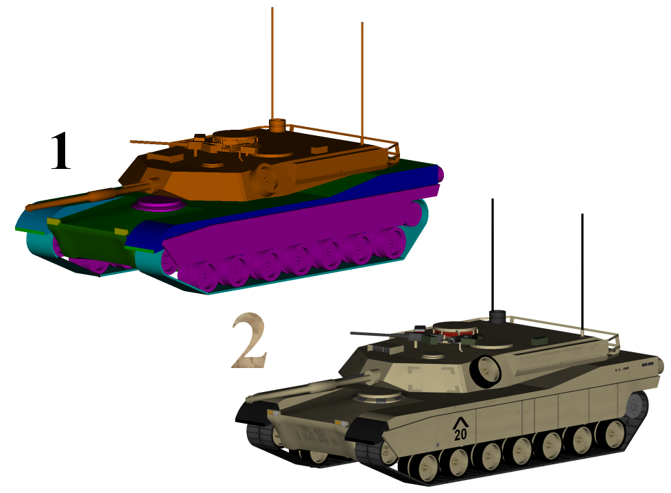
i am working on a game project but setting up the Mats for one of the characters and well i need help on this with the Light Panels
if i can make them like the second image
without buying stuff
cause i am trying to make the shaders almost like the blender ones as possible
@silver holly if you want help, you better start asking the actual questions
what's missing?
don't expect people to understand what you feel is missing by showing images
okay let me put this in more detail okay
i am trying to replicate the light panel we call them aka the purplish bluish light on his arms head and chest into unity with shaders but atm i am having a issue trying to full create it in that way aka i am trying to make them look like how it is in blender
simple way of saying it i am trying to get the unity mats to do the same thing by going from pinkish purple to blue like this
i think its called rim shader but at the same time idk
look into fresnel
ill say this im new to unity so ill be here a bit being kinda stupid but thanks for the help i needed it
Not sure if this might be the right place for this error in cloud build: [Unity] Shader 'Universal Render Pipeline/Lit': fallback shader 'Hidden/Universal Render Pipeline/FallbackError' not found , anyone experienced this?
Hi, does anyone know how to solve this problem I have?
I use shadergraph. I tried switching my master nodes to Unlit and PBR, but the "inner" mesh keeps on appearing at high angles, and gets hidden behind the outer mesh on low angles.
Here's another view of the meshes
left: looking from low angles. right: looking from high angles
@grim tartan You're seeing Unity messing up the render order of these two transparent objects. It's very important that transparent objects are rendered back-to-front, so everything is blended properly. In this case, Unity gets confused because these two objects are pretty much in the same position.
You can force the order that objects are rendered in by changing the Render Queue of the material.
Normally, transparent objects are at 3000. Unity will render all the objects in a given queue back-to-front. So if you change the Render Queue of the inner fire to 2999, then Unity will first render the inner fire and then all the 3000.
It looks like you might be able to use alpha clip for this, because I can't see any semi-transparent pixels. That will prevent this whole thing
Because then they can be rendered in any order and the depth buffer will make sure nothing is rendered on top of something else when it isn't supposed to.
I've tried setting the Alpha Clip Threshold on the master node from 0 to 1
doesn't do anything
You also have to set the render type to Opaque instead of Transparent
In the shader itself
ohhhhh thanks!
but what if I'm trying to achieve the left result?
would setting the render queue higher fix it?
You would have to leave the render type on Transparent to disable ZWrite, so it doesn't write to depth, then you can change the render queue of each to decide which is rendered on top
Whichever has a higher render queue will be rendered on top
Just remember that if you change the render queue, like increasing the render queue of the inner fire to draw on top of the outer fire, then the inner fire will render on top of ALL transparent objects will a smaller render queue.
If you do the opposite, decreasing the render queue of the outer fire, then all transparent objects will be rendered on top of the outer fire.
Actually, one thing you can do which should fix everything is make the outer fire Opaque and use alpha clip
And the inner fire use Transparent and change the render queue to something below 3000
Technically all transparent objects will still be drawn on top of the inner fire because the render queue is smaller, but it won't really be visible, because it will have this opaque outer fire that is stopping any transparent objects behind the fire from being drawn there.
Hmm, wait no that would only work if the inner fire also had ZTest Always
Otherwise, it won't be able to be drawn on top of the opaque fire.
yep, I just tried that
Then you can still leave both on Transparent and mess with the render queue, but know that it will have this conflict with other transparent objects.
If you know that this fire will never have transparent objects in front of it, then you should make it draw last, so increase the render queue of the inner fire. If it's the opposite, there will never be transparent objects behind it, then decrease the render queue of the outer fire
If there's no guarantee, then you'll see these render queue issues
I will increase it then
@low lichen Thank you for the help and in-depth explanation!
I've spent more than 6 hours trying to fix just this T.T
I messed up my explanation, meant to say if you know there will never be transparent objects in front of it, then increase the render queue of the inner fire.
ahhh... I think there would be no transparent objects infront of it except some effects
which might have varying opacity
An alternative would be to copy the generated shader code from the shader graph and change the ZTest to Always manually to do the fix I mentioned before.
But then any time you want to make changes to the graph, you'd have to do this again.
If you just try adding some transparent object and putting it in front and behind the fire, you should see what I'm talking about
Then you can decide if you want to do something more to fix this
yes, I should test that first
Actually, you might be able to use Renderer Features to mess with the ZWrite without having to write any shader code
I should figure out how to do the render queue editing first
ohhh
Transparent objects are at 3000 by default and Opaque at 2000
Transparent objects have to be renderer later so then can be blended on top of opaque objects
I see what you're saying now
reducing my outer mesh to 2999 seems to work
nope
nvm
I'm seeing clearly what you're talking about
Yeah... It's an unfortunate side effect.
But I think there are alternatives
Are you using URP?
I did 3001 to the inner fire. 3002 should go over everything
since 2999 on the outer fire would case more wonkiness
Yes, but that's kinda moving the problem because now the particles are on top of everything instead
right
The alternative is to implement this fix I mentioned about ZTest Always, which you can do without writing shader code by using custom renderer features
You can have all objects on a specific layer rendered in some special way using a custom renderer feature. So you can make an InnerFire layer, assign it on all the inner fire objects and have them all rendered with the Depth Test set to Always
Then change the outer fire to be Opaque instead of transparent.
How exactly do I make a custom renderer feature?
It would be very similar to how its setup in this tutorial
https://www.youtube.com/watch?v=szsWx9IQVDI
Let's learn how to render characters behind other objects using Scriptable Render Passes!
This video is sponsored by Unity
● Download Project: https://ole.unity.com/occlusiondemo
● More on Lightweight: https://ole.unity.com/lightweight
·····································...
He starts making the custom renderer feature towards the end of the video
thanks! I'll watch that
Wait, no, this will have another worse side effect 😩
because it will render over even opaque objects, right?
Yeah
So you can use the Stencil feature as well.
The concept there is you can have objects drawn also write a value to the stencil buffer, which is part of the screen texture, so each pixel has a stencil value 0-255
You can have objects write a specific value on all the pixels they are drawn on
Then you can have other objects only render where the stencil value is set to some specific value
So then you would have the outer fire write some stencil value, like 1, and have the inner fire only render where there is 1
that would mean my innerfire render to be constrained in my outerfire?
Yeah
hmmm... lots of options to pick from. all with side effects
Here's one that shouldn't have many side effects
If you draw the outer fires first, before any other opaque objects, then draw the inner fires with Depth Test Always and Write Depth disabled so it doesn't overwrite the depth of the inner fire, then it should all be fine
Because even though the inner fire is set to draw on top of everything, it will only draw on top of whatever is already on screen, which at that point will only be the outer fire.
and should mean that if there is any object behind OuterFire, it would draw over it, wouldn't it?
No, because the OuterFire is writing the the depth buffer
That's what the ZTest is for. It's set to LessEqual by default, less than or equal. So before a pixel of an object is drawn on screen, it compares its depth with the depth already written to the the depth buffer at that pixel
And it will only draw it if its depth, its distance from the camera, is less than or equal to the current depth
The depth buffer is just another channel of the screen texture. There's red, green, blue, alpha, depth and stencil
So every pixel has a depth and stencil value too
how do I do that? do I compile and show code?
ok, so I make a forward renderer from URP first
nvm, theres the Renderer Feature button right there
It might have changed since this tutorial
ye I think the inspector editor one is now Forward Renderer
Renderer Feature is now just a pile of code
Well, that is one option, but there should already be a pre-made Render Objects custom pass
Did you try to follow the tutorial?
not really, since I did figure doing it would render over even opaque objects
I will go watch it then
You could technically do the same thing with just render queues, if you could change the ZTest to Always in Shader Graph
Unfortunately, you can't unless you generate the shader code and edit it to add this line manually.
I think that would still be easier than setting up this renderer feature
And wouldn't take up 2 layers
Of which you only get 24
let's just say I'm going to avoid that and use Stencil. just a question now: Stencil still technically renders the object, but is alpha locked by an object with the same stencil value?
so its still 3D

Still playing around with Stencil shaders. This one gives the effect of "cutting" into geometry. #unity3D #madewithunity #shaders 👀✨ https://t.co/EHfFqGXjKk
Likes
166
You can think of it in screen space. It's like a mask on the screen. First you draw some meshes that write some stencil values on the screen. Then you can have other objects only be visible wherever the stencil value is equal/less than/greater than/not equal some value.
I see. I could say I understood 99% of that explanation
This is how scroll views are implemented in Unity. First, a box is drawn where the scroll view is and it's writing some stencil value. Then all the contents of that scroll view are set to only draw where the stencil value is the same as whatever value was written by the scroll view.
The order is important. First you have to draw the stencil writing mesh to ensure that when the stencil reading mesh is drawn, there's already a stencil value written.
ok thanks for everything! Though I will certainly return if I get any more errors
desired shader compiler platform 9 is not available in shader blob is the only error I get on iOS from the shader compiler. both on GLES2, 3 and Metal. What would be the first* way to start resolving such an error 
this started happening after switching from LWRP to URP.
Android builds work correctly
the game also works correctly in editor both on windows and mac
@rain niche Do you have any #pragma target x.x in the shader?
Has to be in a code block, rather than inline code
A bot is clearing it as spam and you'll get muted if you try it too often
ok
but target is 3.0
prefer_hlslcc gles, exclude_renderers d3d11_9x
3.0, should be fine
Then I'm not sure. Have you googled the error?
yes i have, the google suggestions are really bad. suggesting switching to GLES3, which is depricated, and besides it doesn't work
So this is for a specific shader that you made?
all materials
Then it must be some issue with URP
but yeah they are custom materials, but they used to work fine with LWRP
That maybe you can fix by changing some settings, but I don't know
ok thanks
@grim tartan a considerably easier solution for the fire would be to flip the culling. I have a snippet a few windows above intended for use with cell outlines, but it fundamentally does the same thing. You're interested in changing the Cull attribute of the pass, the rest of the offset stuff is necessary (but could be used)
you would want that enabled on the red parts, but leave the interior white part as-is.
It wouldn't look exactly the same. I think they are already doing no culling, so presumably they want both sides visible.
would still suggest over the 'no culling' approach as that feels like a hack for a different issue
I thought of 1 thing, maybe I can just invert the normals on my 3D model, giving the same effect?
or is that what you meant by flipping the culling?
@gleaming moss
Actually ye... maybe I should just flip the normals on my outer flame mesh! I should try that right now
@grim tartan they're not 100% interchangeable, but most export pipelines will do the thing that makes that work. That would mess up your shading too, but I think that's just a flat emissive color
but wouldn't that make it viable in my case? I only need to use it for flames. and they dont cast shadows. plus theyre just flat colors too
yeah that's fine, just pointing out that solution will do a few other things. More 'be aware of how this tool works'
I see... well I know the other options I can do thanks to your help earlier :3
incase this one does give me problems
it might be relevant if, for example, you add a faint fresnel effect to tint the outer region to a different shade of red
you'll need to muck with signs
flipping normals might actually make that easier tho
o.Smoothness = lerp(_BaseSmoothness, _PuddleIntensity, puddleUV.r - _BaseSmoothnessThreshold);
Trying to make a 'puddle' shader using a grayscale noise texture and smoothness (basically a smoothness map) but I'm having some problems.
Basically I want two values:
BaseSmoothness
PuddleSmoothness
Puddle smoothness is the smoothness/wetness of the puddle where 1 is completely reflective and 0 is dull.
Base smoothness is the same but is the smoothness of the object where there is no puddles (which is/should be the black parts of the noise texture). I thought the best way to do this is by lerping between the base smoothness, the puddle smoothness (called puddle intensity in this case) with the third argument being the puddle textures red channel but this doesn't seem to work. I get either sharp cutting off points for the puddles or the base smoothness is affecting the puddle smoothness, which it shouldn't.
@harsh marsh is puddleUV the output of the texture sample?
It's a weird name for that variable if so
I would think you would just need to add the puddle smoothness to the base smoothness and clamp/saturate it so its within 0-1 range.
o.Smoothness = saturate(_BaseSmoothness + _PuddleIntensity * puddleUV.r);
basesmoothness is still affecting puddleintensity tho which I don't want (basesmoothness is the smoothness of the object itself and is independent from the puddle's smoothness/intensity)
Then how about using the max of either value?
o.Smoothness = saturate(max(_BaseSmoothness, _PuddleIntensity * puddleUV.r));
that seems to work fine! thank you @low lichen
aaaaaaahhh
finally found a solution, and i KNOW why: there is one step that needed to fix: it's in camera and you have to uncheck in this part:
so apparently the video about see-through didn't mentioned about that part XD
the solution was from this video: https://www.youtube.com/watch?v=F3XCsbLlqAQ

meh... i spoke too fast...
it didn't solve the problem
here the problem
i almost solved it ^^;
hello, I've gotten a billboard effect in shadergraph for a lens flare quad to face the camera, I'm having trouble trying to find a way to limit this.
such that if the object is actually facing lets say more than 90 degrees away from the camera that it stops billboarding.
can anyone help?
            o.Albedo = c.rgb;
            // Metallic and smoothness come from slider variables
            o.Metallic = _Metallic;

            puddleTex.r = _InvertPuddleMap == 1 ? (1 - puddleTex.r    ) : puddleTex.r;
            o.Smoothness = saturate(max(_BaseSmoothness, (_PuddleIntensity+1) * puddleTex.r));
A problem with my puddle shader at the moment is that the puddles are impossible to see on light objects. What I want to do is feed the puddle noise texture into the albedo to make the albedo darker in places where there's puddles
issue is, it makes the puddles too dark on already dark objects (c.rgb-puddleTex.r)
@umbral trench I don't get what you mean when you say "facing more than 90 degrees away from the camera" ... like, when you look at the billboard from top to down ?
I mean, that's what bilboards are for, to always face towards the camera, not away 😅
@amber saffron here's a very rough sketch for what I mean, I have the flare quad on a billboard so it doesnt get distorted when you're looking at the light from a angle, but when the light it pointing away from you, I want to stop the billboard/hide the quad.
okay got it
If you want to go full shader route, you could use one of the object pivot axis DOT the camera direction to detect how it is facing the camera
Use a step on this value and multiply with the billboard transformation to either be billboard or 0 in position
I have a shader that clip it's content based on a render texture, works great in the game but doesn't work well in the scene view since the objects screen position doesn't match the render texture
is there some way to detect if the object is rendered in the scene view
@amber saffron thank you, I'll give it a go
so I can disable the effect
Wait.. I can probably just make a script that change the camera to match the scene view
how would i go about adding an emission onto a trail?
In what pipeline?
Hello,
I do not have a lot of experience with shaders but I have a question related to the Universal RP and 2D lighting if anyone has an idea. When using that lighting system, is it possible to use anything else for floor apart from Tilemaps?
I don't know if it is possible to use Terrain or a Mesh with a material
@amber saffron I'm doing this wrong aren't I? lol
How can I improve my puddle shader? It maps smoothness to a noise texture. White parts are completely wet/smooth while black parts are the objects defined smoothness (called the base smoothness in my case)
It also uses triplanar mapping to stop puddles from defying the laws of physics and appearing on vertical walls
one thing I was thinking of was taking into account the normal map/a heightmap to make the puddles appear at certain 'heights' (like in cracks and crevices before the rest of the object) but I'm not entirely sure how to tackle that
@umbral trench Yes, I think something is wrong here :)
Gimme a min to try it out
Here :
When applying this shader to a quad, the quad will only be white when globally facing the camera.
The input of the transform node is the axis of the object that you want to compare to, and the step threshold is the "toggle".
1 beeing full facing, 0 is 90° and -1 is back facing.
@harsh marsh I give a ➕ to the height controlled puddle.
Search for "height blend", it might help you.
Also, if you're working with shadergraph, we have a subgraph for this here : https://github.com/RemyUnity/sg-node-library

GitHub
Node library for ShaderGraph. Contribute to RemyUnity/sg-node-library development by creating an account on GitHub.
@amber saffron wow, that works great! thank you so much!
yeah I'm not using shader graph atm sadly (I'm not using a project with LWRP/HDRP atm)
but considering this is my second ever shader im proud of myself. I'll look up what you said
hm
everything I'm finding is either:
Shadergraph/some other node based shader tool (like amplify)
Height blending based on vertex position (for stuff like terrain)
look at this : http://untitledgam.es/2017/01/height-blending-shader/

Many of the shaders I find myself writing require some sort of blending between textures. The most common example of this is for terrain shaders, or shaders for terrain type objects. These are usually controller by a splat map, where each color channel dictates the amount of a...
yep just found that. thanks anyway
The example is for terrain layering, but you basically want to use the height to modulate your noise
yeah
Bit confused on this. Since I'm only using 2 textures (1 for the noise, 1 for the heightmap) I'm not sure what I should use for input2/height2
float heightblend(float input1, float height1, float input2, float height2)
{
    float height_start = max(height1, height2) - _HeightblendFactor;
    float level1 = max(height1 - height_start, 0);
    float level2 = max(height2 - height_start, 0);
    return ((input1 * level1) + (input2 * level2)) / (level1 + level2);
}
``` @amber saffronQQ. I have an iOS Unity Project where I am getting weird artifacts after I have switched my project over to iOS build settings. The culprit is in the red outlined square. Any ideas? Links to files here (https://drive.google.com/open?id=1ftJ-y6vGNtt1jM8u01oXr8zSia4SMt3G&authuser=stanley@dragonarmy.com&usp=drive_fs)
Full image here
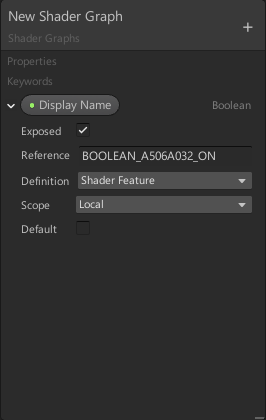
Has anyone gotten keywords in shader graph to work in URP, or is there an example project I can look at that leverages them?
@lime viper what are you trying to do?
Enum for UV set selection
boolean for feature implementation
I haven't been able to get a boolean value to show up on the material inspector
and Enums seem to only choose the default value
It needs an "_ON" at the end of the reference to be exposed in the inspector
wasn't there some branch node or something for features?
last I heard the branch node is shader code based branching not compile based
ah
but what use would these keyword be if it didn't use something like that in combination?
I haven't actually tried this myself since this stuff was added after I tried something like that in past
The keyword creates a node similar to the branch, with an on/off state
that makes sense
so here is the last one I was trying:
they probably still haven't exposed the master node keywords tho?
in past, you couldn't toggle on/off the master node variant from the material
Yeah some of the features that aren't exposed are frustrating, double sided almost always should be set on a material
hmmm, wonder if the keyword thing is new and not forward ported to 8.x.x
because I totally don't see this on my end: https://docs.unity3d.com/Packages/com.unity.shadergraph@7.2/manual/images/keywords_boolean.png
I get
oh my bad
Yeah the documention seems pretty sparse and I've been trying to find any example to make sure I've not effed something on my end
That's a property boolean, not the keyword one. There's a "Keyword" under the + dropdown
there's separate keyword entry type 😄
yeah, I spotted it right after 😄
that's not intuitive at all
why not have the checkbox on regular properties that are right type
oh they have multi compile + shader features both here
and scope too, so same deal as on regular shaders
this is completely broken on the version I'm running here 😄
but it's wip branch so..
I'll try with 7.2
I'm really stoked to try to use them to simplify my support burden but I've been having some issues with getting them working
is it possible to have 2 emissions on one shader?
this does explain things, I was playing with custom pass SG version from github earlier and it was broken af, but it probably really was that 8.x.x/release branch has broken SG in general
as it totally doesn't work here at all for me, just bunch of errors
@silver holly if you just mean multiple maps or colors then it's pretty easy to do in shader graph
thank you thats all i needed to know ill try it right now
I wonder if the keywords work but the editor is just not kicking off a recompile when the option is changed on the material inspector
Just tried it out, the enum keyword definitely seemed bugged in 7.1.8, as you say, editing it in the inspector isn't triggering it to recompile (except the last enum value which I think is the "off" state so works differently).
Just upgraded URP to 7.2.1 and I still can't even add new entries onto the enum in the blackboard, it just causes errors (ArgumentException: Slot could not be found)
Hmm, it does seem to be updating now though when changing the value in the inspector
Any good learning resource to learn and master shader graph?
including coding shaders by hand
you can look for the pinned messages for some resources
Interesting, I wonder if I'm not seeing the update because I'm on asset pipeline V2, or if it's because of a cache server
Hi All, I'm trying to do a full screen grayscale effect EXECPT for a certain layer/material/shader. I'm unsure what is the best way. I'm using URP (will be upgrading to latest sometime soon). I see a few ways
- Using a PostProcessing effect + camera stacking (camera 1 everything i want gray, camera 2 the colored parts)
- Change my whole game to use the same custom shader (shader graph) which will have a grayscale toggle
- like above but i'm swapping materials
any advice on which would be best
best for me would be easy to implement and extend with minimal performance cost
Use a custom render pass to draw exception objects to a stencil or buffer. Use that stencil/buffer in your grey scale pp effect to not grey scale those areas.
cc @empty spindle
There is a render layer you can use. It's a bit old, but you may find some ideas in this per-object bloom example. https://github.com/johnsietsma/ExtendingLWRP

GitHub
Examples for extending the Unity LWRP. Contribute to johnsietsma/ExtendingLWRP development by creating an account on GitHub.
Can I use a keyword to switch the master node in SG?
it works in wrong direction for that
would be nice if you could swap the target master node with it
and let even swap the whole master node type, instead of just settings
@devout quarry
if there was like, a way to wrap the masternode inside #if defined and then put the keyword switch node after it on extra pass, it would work but there's no such mechanism on SG
Alright thanks
Another questions
How do I know if I should opt for a texture or noise on mobile?
I read somewhere that as a general rule textures are always better than noise functions on mobile
but on the other hand I read somewhere that texture sampling is expensive
Is it a matter of finding out if I'm CPU or GPU bound? and if so, how do i even figure that out, the GPU profiler isn't working for my mobile phone
Currently optimizing is really bothering me, I find it hard to know what properties of my shader are my bottlenecks
@empty spindle Draw it the right way, the first time, once?
What determines if it's grey or not?
@devout quarry Shouldn't be CPU issue..."noise" can be/is generated on the GPU.
The question is "is math faster than texture sampling" and the GENERAL rule is ....favor math over lookups. BUT, if the math is real complex, and the results are summarized neatly in a texture, the texture COULD be faster.
In general, favor math over sampling. Even on most higher end mobile these days. YMMV on the low end, sampling is probably faster, except for the simplest calcs.
For HDRP, what's the best way to get some grass geometry in my scene? Seems like geometry shaders are a no and compute shaders are under-documented. Anyone know how to inject some GPU grass into my HDRP project?
I got a compute shader generating some geo, but I don't know how to draw it in HDRP. The Graphics.DrawProceduralNow assumes you know what buffers to fill and that you're drawing at the right time...
@uncut schooner You can add geometry shaders to your HDRP shaders just like you would in "regular" shaders for the legacy pipeline. It does require you to understand how HDRP shaders work and how to modify them since afaik there is no support for geometry shaders in the shader graph.
https://github.com/keijiro/TestbedHDRP
Keijiro Takahashi from Unity has some geometry shader examples for HDRP in this repository, but they might not work with the latest HDRP/Unity version and need some minor changes
GitHub
Testbed project for Unity HDRP (High Definition Render Pipeline) - keijiro/TestbedHDRP
@devout quarry If you can't get the hardware vendor's profiler to work, you have to make test cases with isolated variables. Do one with texture sampling, one with calcs. Time them over several runs and average it out! Change as little as possible between types of runs to isolate changes. Try to avoid changing two "variables" at once. You should be able to sleuth that type of stuff out without a profiler.
Currently optimizing is really bothering me, I find it hard to know what properties of my shader are my bottlenecks```Alright thanks for the info
Another good way to debug shaders quickly on mobile is to add keywords that you enable/disable from script to try two different approaches.
I like that, thanks
So just to be sure
a keyword is not a 'branch' right?
It's like a shader keyword, and it might make compile time longer and bigger file size
There was debate above about keywords not doing conditional compilation. So beware.
but performance wise it's the same
No branching.
my keywords so far seem to work in SG
I see the shader recompile when I turn it on/off the first time
Look at the source, I haven't tried it yet. If it's conditional compilation, fine.
okay will do
You'll likely see that on device as well, because it's loading the new shader variant
It's good to figure it out, but if it's simplier for you, just have two shaders...one with textures, one with math. Swap em...if that works for you. Or edit it. Whatever.
Anyone getting decent URP performance on android? I'm getting 45fps with a god damn plane and some vertex lights.

@grand jolt 
@neon gull alright thanks!
ok this probably been asked before but why does the example code posted in unity manual for postprocessing, on lwrp produces a triangle?
🤔
@grand jolt Is it supposed to be a full-screen triangle for post processing? That would make sense (and it's what I use now, even for standard pipeline). Better than a full screen quad.
(He's muted) but he wants to use an SG shader in a URP fullscreen effect.
Would it be advisable to use an image effect shader when designing an effect that only affects the background? i.e. a gradient in the bkg - or should i just slap a big ol' quad in the background and render it on that. Given it would require me to get creative with depth and masks and the like..
more of a design question I suppose
@full sail Could you just use a custom skybox shader? P.S. What pipeline are you using?
@meager pelican I considered a skybox shader, might be a decent way to achieve this effect, but if my background get any more wild, wanted to know how to build a shader like this properly - might dig into the code for those, thanks!
Uhh pipeline is currently the built in rp, but it's eventually going to be aimed at a mobile device, so potentiall lightweight?
OK, you should decide now, IMO.
But...anyway, standard pipeline will run on mobile too.
The skybox is called after opaque and before transparent. So it can leverage depth clipping and not-draw where it doesn't have to, but be there so transparent can draw over top of it.
URP is supposedly better, but it's more bleeding edge and less documented.
@meager pelican I'll go research the different pipeline and their benefits/drawbacks - thanks for the info, that's interesting so the masking becomes sort of implicit (opaque masks itself) and transparent just draws over the top to whatever opacity?
So far my image effect tests have completely drawn over everything in the scene - but that's probably me not being explicit with the order/clipping
I'll do some more digging - thanks a lot, good to know I'm on the right track
so I'm doing some threshold/height blending and I'm opting for using a subtract into a smoothstep with a "thickness" value to tighten the blend, is there a better way to do this? e.g. cheaper, or more standardized
So I've got a LWRP effect working with the shader graph, which works delightfully well but only when the camera is in perspective mode
it relies on depth - is depth handled differently when in ortho?
the effect suddenly becomes locked to the camera's vertical position, where it isn't in perspective mode
@lime viper id expect that to be fast, You could refer to hdrps layered lit shader code but it's a more complex weighted blend (looks at the height and contribution of each layer)
I'm trying to find a projector shader that lets me display Opaque projections. I have found a few but each one makes my entire ground plane white whenever they are enabled. I know absolutely nothing about shaders so i was wondering if anyone might know whats wrong. I can post the shader i found if necessay
Thanks, good to hear, I'm always a little worried when a single node solves something that it's hiding a bunch of cost
does anyone know why something like WebGL: INVALID_ENUM: bufferData: invalid usage seems to be happening (not unity related specifically but idk where else to ask)
Getting an error like this in typescript for an angular application, and people here seem like the best option to get some possible info
@tidal rover Are you writing any shaders or using WebGL directly in this Angular application?
Any HTML5 canvases being used?
@low lichen this is going through three.js which handles most if not all of the rendering
i pass it an object in buffergeometry, and I know the geom is valid
how do I texture all sides of a cube differently using shader graph?
@terse nexus Don't use the unity cube and have separate UVs per face
Or filter the face by using the vertex normal, but that's overkill imho
Hello, im new to shaders. I've seen a tutorial today that showed how to apply Fresnel effect node to PBR Graph, but it was on a sprite. Can i do a fresnel effect on UI Image? I'vre read i have to use Unlit Graph but Unlit Master doesnt have Occlusion
@regal stag i now know why it's not working, it was due to this message:
@fresh spire What shader are you using for the sprites?
I think it might be because it's using the built-in sprite shader not the URP one, could be wrong though
Wait what isn't working though, I thought we had it working?
to be honestly, my game project is a mess
not really,
now it's the render order that annoy me
Because of the curtain/effect showing ontop of the game over screen?
yup
I think the easiest way to fix that would be to put the game over screen objects onto a new layer, and use another RenderObjects feature on the forward renderer to render them after the effect
i see, though, i have this list:
Either that or the new camera stacking / overlay camera could render the game over screen separately and overlay it on top. I haven't used it yet though so not sure how it works
hum
Would the gameover screen be in menuUI? or is that the stuff at the top of the screen?
oh
you have a gameover layer, nvm
I take it the gameover screen is on the gameover layer, right?
based on the frame debugger, i noticed that the momoobehind and momoofront are completely separated from the renderer transparent
as shown:
@full sail You may be interested in this thread which explains ortho depth a little : https://twitter.com/Cyanilux/status/1169932943869059073
As well as this post :
https://forum.unity.com/threads/fresnel-effect-does-not-work-with-orthographic-cameras.807240/#post-5358849
@fresh spire Yeah, so that's how the RenderObjects features work
It's why changing the Render Queue of the materials, or sorting layers for sprites won't change where they are rendered in relation to the normal Transparents
And it's only after the transparents because of the Event on the feature, which puts it After Rendering Transparents
@fresh spire So what you could do is this, have another RenderObjects feature to render the gameover layer, and exclude it from the default layer mask (so it doesn't render in the normal queue, which would result in rendering it twice)
ooh Transparent Receive Shadows, that's new
that is what i'm wondering why it's rendering before everything
@dusk agate I'm a little confused about what you mean. The Fresnel Effect node relies on normals of 3D geometry to create the fresnel/rim effect around the object. It won't produce a outline on sprites or UI objects which are rendered to quads. (It could also be put into any master node input, e.g. Color, it doesn't require being put into Occlusion)
@fresh spire Why what is rendering before everything? The gameover screen?
hum nevermind, after looking at your pic, i noticed one thing: apparently my layers order are messed up:
I don't think the order of the layers actually matters
hum
I think the order of Sorting Layers would, as that's what are used to sort sprites. But that won't sort objects in the render features
Is it possible to input texture from vector instead of texture2d and still be able to offset it?
Huh? Little confused about what you mean. The Texture2D input is what defines the texture to sample. The UVs (Vector2) is the coordinate that is sampled.
Are you trying to offset the vector2 from the Combine node?
I'm making normal map from height subgraph and I need to its input be vector, so I can use procedural textures for it too.
It's working, but I can input only one image texture to be made normal map.
You can specify a Texture2D property if you want to be able to swap the texture out
I know, but I want to use vector instead of texture2d.
So I can input to this subgraph things like procedural noise.
oh hey @regal stag hadn't realised you were in this discord! Was following your tutorial for height fog 😅. I'll check out that thread, thanks.
@burnt ether Okay... I think you just want to remove the texture sample nodes and use Vector1 outputs instead then. Since you have four, probably best stored as a Vector4 which can be put into a Split, then into the inputs where each texture sample is currently.
@burnt ether Are you aware that there is a Normal From Height node though?
I know about this node and it creates very ugly result.
I see
Are you sure the "ugly result" isn't just in the preview though. It might be different in scene/game
In scene it's also ugly.
It's just 4 different procedural generated noise samples per pixel seems like a lot of calculations to me.
I think that the normal from height is the best it's possible to do without having a lot of calculations (based on ddx/ddy).
If you want to go the route you have without textures, you basically have to calculate at least 3 times your procedural height for each pixel
That's how normal from height looks like - very pixelated
@regal stag solved the fog issue with that thread, you're a god
There's also another problem that I can't solve - why does Scene Color node in HDRP burn everything behind it?
Because it doesn't take in account the exposure
Can I workaround it?
You need to apply it like this :
Doesn't work
I'm just trying this right now, and it does work ...
Unless something else is messing with the rendering
In HDRP?
yes
Puddle shader I've been working on
looks good
Im trying to make "holes" in my cloud mesh, but adding a simple noise causes this artifact. Any good ideas?
Bad UVs ?
I donno
Yeah looks like a UV problem. Maybe you mean to sample using world Position rather than mesh UV channel.
How do you sample the noise for position offsetting?
Umm which noise? I have many, plus I'm new to this
You appear to be offsetting the vertex position based on noise. It might have an input into the UV input on the Simple/Gradient Noise node.
better at least, now how to smooth the edges
How to smooth : Remap the noise to have a very small 0-1 transition where you want to cut to be, use alpha treshold at 0 and set rendering to transparent
how do i make an Unlit shader graph not write to the depth buffer?
@stiff flower I think the only way to change ZWrite is by changing from Opaque to Transparent
@low lichen ah... yea i don't even see that as an option in the basic Unlit, but I just made a graph with the HDRP Unlit master node and i see a dropdown to make it transparent
Hey, has anyone ever done DXT compression on the GPU for Unity ? I am doing a lot of render to texture stuff and compressing the results directly on the GPU would be great (targeting PCVR)
HDRP does built-in BC6H compression for environment maps, source is available on Da Git
quality is not great but that's A) known and B) less of an issue for their applications, possibly yours too
@long rune think you might have to add planar uv's to that mesh in whichever app it was made in, otherwise you'll keep seeing issues, it looks like it's broken into multiple uv islands so you're getting splits in the noises
also its blocking my directional light, how to fix?
https://cdn.discordapp.com/attachments/401076282869415946/682668954144997376/unknown.png
Launching built game to this error. I have DirectX 12

Uhhhhh, so i have no idea why the top texture is stretching like that but nothing i could think of fixed it;
you're only ever getting the .xy component of position to input to your texture UVs, is that what you want? you likely need to split the position vector to do proper triplanar mapping
just glancing, i'm pretty sure your grass texture needs to be using the .xz components of position to map correctly
@neon gull You were right, thank you very much! Got a grass geometry shader working in hdrp from the examples you showed me.
@stone sandal Sorry i was busy, annnnnd that might be the source of my problems
Still having the same problems
@sonic bear You may have them mixed up. Try switching them around a bit
Your grass texture sample is the middle one right? So it should be using R and B. The other two need switching too.
I did that and got it, although the other (top and bottom, the two side ones) are stretching weird now, but passing just the entire world position into themseems to fix it
Really simple question, how could I made the node on the left look like the one on the right? (I just used levels in photoshop, anything similar in SG?)
replace color?
Probably just a Multiply?
@sonic bear If you pass the "entire world position" into a Vector2 it will be equal to using the XY / RG components only.
For the Z axis, it would want to use the XY components. But for the X axis, you would want to use YZ.
@shell walrus try a multiply tab like Cyan suggested, a replace color might also do what you are thinking?
I dont know why using the splitting them would cause weird stretching and rotation where shoving the world position into it wouldnt
hmm that doesn't seem to do it either. As for the replace color I'm not sure how to use it
It would be causing stretching if the inputs were using the wrong components for each axis.
@shell walrus I mean just Multiply it by a single value like 20 or something, rather than a colour.
So you put the graphic you want to replace the color of into the "in"
you select the color you want to replace in "from"
you can use a color or texture to switch it to in "to"
and range changes how much of the color gets replaced
and fuzziness changes how fuzzy the changing is
I used replace color a lot in this mess of a shader to make the foam and whatnot
Look at this thing
I am happy now
I have an odd bug that I ant find the solution to anywhere where, when i disable the gameobject, the shader changes back to the base shader. Any help would be appreciated.
@uncut schooner is that grass for terrain system or was that a shader for mesh grass?
@grand jolt It's just a geoshader for a mesh
it has some blending for three texture sets by vertex color
is that possible to use a shader to compute a distance texture from the camera to the rendered world ?
similar to how physics raycast is returning the distance form the camera to the world
but using a shader instead of a million raycasts
( 1080p ~= 2m pixels )
Depth texture?
I mean, that's what you can get from the camera
oh wow didn't know camera.depthTextureMode is a thing
depending on your rendering setup this texture gets rendered anyways (in deferred mode) so there is basically no additional cost when using it. In forward mode you'll have some overhead
^ unless the forward path does depth pass anyway, like happens on HDRP
hey guys
does anyone know how to write ShaderLab script ?
I am trying to apply a color to a shader
I just cant get the color tint to work
^^ Finally! A non-node question! Praise the standard pipeline gods!
So multiply the calculated color by the tint color. Problem solved!
Need an example?!?! Party favors? I can publish text and you don't even need pictures!
@mild mesa
The default shader that it generates when you do a "create shader" operation already does that if I remember correctly.
Anyone experienced shadergraphs material becoming black on play mode?
Is it working in the scene view in the editor, or are you just talking about it working in the SG previews?
Do you set any material attributes in scripts?
I dont set any material values and as soon as I change sth or save, it shows up again in sceneview. Hitting play makes it black again. @meager pelican
Uh. Sounds like something isn't initialized, or you have a serialization problem. But IDK what. See if you can inspect an object under a debugger, check the material values and/or go to the next step and follow the draw calls in the shader tools (like PIX if dx12 or renderDoc or even vendor tools). But I'd start on the material/c# side first. Maybe others have better ideas.
@meager pelican fixed it bro
Wondering if I can pick your brains here? I'm on a team helping to work on some hypercasual mobile games and need to figure out the right lighting/shader setup. My ideal is that a prop would 1) have shadows cast by a single real time light 2) I would color via vertex colors and 3) be PBR. I don't really know how to continue exploring this, do my requirements contradict each other in any way?
bro i have no idea about shaders spent about 9 hours writing 1 🙂 @shell walrus
@shell walrus You can do that.
What pipeline do you want to use?
Do you want additional lights or emissives?
I'm likely to use LWRP
What about GI (bounced indirect light? stuff like that?) Do you want to "keep it simple?" but have shadows?
Potential light baking but possibly not due to file size
Yeah, I couldn't find a GI option in my setup that wasn't baked?
and surely real-time would be too expensive?
It's very much flat colors/gradients
with PBR
Yeah, depends on your target platform.
OK. Maybe PBR is overkill too? Do you need it, or just specular type stuff?
It would be a wide range of phones, then turn off some aspects depending on model
Well, if you don't want realtime and you don't want baked, there's only so many aspects left to turn off.
;)
The reason I asked:
PBR would all be done via 1 material with 256x256 textures
is that if you only have one directional light, you can do that in the coloring pass and then just have a shadow pass since you're not baking additional lighting. But if you have more than one light to compute, it gets more complicated. (Glowing stuff, whatever).
But for one sun, or one torch in a closed room...that's directional somehow... it's inline lighting. Like blinn-phong upgraded to PBR with a shadow pass.
IDK someone with more new-pipeline experience will have to guide you, the SG shaders have some overhead I'm not fond of (they end up initializing several components twice, etc) and they have their own lighting models.
Hello! could someone give me advice to learn shaders? thanks!!
There are tons of tutorials on the network. Did you watch them/ read them?
@meager pelican Just fyi, upgrading to new version of Unity fixed it. I guess there is some fancy stuff going on in addressables pipelines
No, I'm going to start learning now, I asked because maybe someone could give me advice in the path to optimize time, it always pays to ask haha
There's a few resources in the stick-pin (sticky) above. Like "gentle intro to shaders"
Okay, it did not help... Oh unity, can you do one thing right? 😄
Oh, now I get an error like : Shader warning in 'Shader Graphs/Comic_Shader': Output value 'vert' is not completely initialized. Whatever that means
That’s a graph error that we resolved in 7.2.0
It was a hot fix though that I’m not fond of, but the 20.x tech stream this year will have a much more elegant solution
So should I install 7.2.1 even if it does not say 'verified'? @stone sandal
well I’ve been using it for weeks without much issue 😉 ymmv but it’s got a lot of bug fixes compared to 7.1.8
Let's try. 😉
Could that be the issue about my shadergraph showing black when hitting play?
Guess not, as it happened randomly today and now persists, but lets see if this patch is helping. thanks for your clarification and help 🙂
Okay, does not change a thing on black sprite shape. anyone an idea?
@stone sandal does this sound like something useful to you? InvalidOperationException: The native container has been declared as [ReadOnly] in the job, but you are writing to it.
You should really file a bug to us if it’s happening consistently, I can’t do much without the full error report from our bug system
Well, in the last 7 days, I recieved like 10 different bugs. With a project close to a deadline 😄 So yeah, excuse me for not having that time to bug it right now 😉 Just thought, maybe this has happened before aond someone knows something
@stone sandal I figured it out. I hate a gradient going all over the spriteshape dependend on it's size. Seems like the spriteshape was too big and therefore the texture got too big and got removed. Just so you know
in Shader Graph does anyone know if it's possible to change the shape of the Sphere Mask? as in...could it be made square/rectangle?
Yes, use a rectangle / polygon mask 🙂
i tried multiplying the sphere mask output with a rectangle, but the rectangle only applies on the object UV rather than combining with the mask shape
if that makes sense 🙂
i'll try it out, thanks
If you need 3D versions, there are a bunch of signed distance functions here : https://www.iquilezles.org/www/articles/distfunctions/distfunctions.htm
They aren't written in HLSL but wouldn't be too difficult to convert. Could be used in a custom function node, (or convert it all to nodes I guess).
Tutorials and articles of Inigo Quilez on computer graphics, fractals, demoscene, shaders and more.
May need to negate & put the value through a step/smoothstep to get a similar output
same thing occurs, the sphere mask is unaffected, the object UV is changed by the rounded rectangle
@regal stag yeah i recall the SDFs used in that guy's parrallax pokemon card. i'd hoped they were a default node in SG but i guess i'd have to add them as custom functions
i'll look into it, ty
ooh my card
if you have any questions about those nodes, I'm here @tight forge
Like cyan said converting them isn't too hard
and then I use fwidth to sample them
Hello,
I'm wondering how would it be possible to make anything inside a specified volume change materials. Take this simple example:
I have a gray mesh and a sphere (my volume). When I move the sphere around. every surface inside that sphere should look differently. Of course all 3 dimensions are respected, so if something is BEHIND the sphere from the camera perspective, it is rendered normally. Only stuff inside the volume gets affected.
Anyone got any ideas?
Use the same "smart" material (shaders are materials anyway + settings) on all of them, and have globals for sphere location and radius. Do different things depending on worldPos location to the sphere center.
That's one way. Another is more complex with multiple passes.
But since you're shading PART of an object differently, you have to do it on a per-pixel basis, and thus you can't just swap materials.
And it may depend on "what's different"....
Sure, I meant a shader - not swapping materials. Just used that word for simplicity. 😉 And the sphere was also a simple example. I want to do it with any mesh.
I wonder if It is possible to use meshes as volumes (kind of) be it by shader scripting or using shader graph or ASE. I also considered creating something like a decal system with non-box projectors, but I didn't research this thing yet.
Do you think any of there ideas make any sense?
I still don't know what you're trying to do.
But, since ultimately, it's a 3D world projected onto a 2D plane, if you can compute the intersection with your object, or at least the 2D stencil outline, you might get away with a stencil and a post processing effect, depending on what "different" means. You'd have to draw the "special" object first, and maybe use layers. And then your "other stuff" would know how to draw itself. For example. Or apply a PP effect after the fact.
IDK. Think about it.
It depends on what you're really trying to do.
It could be as simple as changing the albedo color of everything in the volume. I've already considered what you wrote above, but the depth texture I can render is.. well.. 2d. That's a problem, because it doesn't give me the info about the geometry of the volume that's pointing away from the camera.
So as far as I imagine it would only enable me to calculate whatever intersects with the front of the volume.
Uh...sphere intersections for that are easy. Anything more complex is....more complex. If you want to "see through" the object and see two different effects based on intersection, yeah, that can be tricky. You'll need to compute an intersection to the volume of the "special" object(s)...because just depth won't tell you "inside or outside" the volume.
You can convert depth to worldPos though if you can compute that irregular object intersection for a point.
Can you say what type of effect you're after?
Literally what I stated above - changing albedo from white to some other color. Maybe emission as well.
But your object is...irregular and any mesh?
The geometry that is going to be changing is a large city.
This is quite irregular so I can't just slap a postprocessing overlay using my volume.
What @grand jolt and I (and others) kicked around was for spheres, so it was easier. And there were multiple spheres. It was B&W vs color
I mean the volume within which the color changes. Spheres are easy. Other things tougher.
Is there a way to easily extend the default Sprite shader?
Without duplicating the shader
I mean the volume within which the color changes. Spheres are easy. Other things tougher.
@meager pelican Yeah, I figured.. Hmm, I think I'll just go the completely different route. The volumes are built from predefined shapes at predefined locations, so they're predictable. I might just cut the city mesh into those segments and actually end up swapping materials for those segments. It'll be a hell lot of work because of how big the city is, but at least it's a simple solution that can be completed in predictable time and it won't require additional GPU load.
Thanks for the brainstorm anyway!
@zinc cloud No, not without duplicating the shader.
If it's all fixed, you could maybe do a materiel property block for those pre-cut segments, depending on the change, rather than actually swapping the material. A boolean property basically. Might save some time. All depends on implementation details.
Yeah, that's a way too.
(Probably faster, but guessing due to unknowns)
@low lichen Alright, I'll have to do it then :/
I'm having a hard time wrapping my mind around this... I want to have a float property with a range of: [0,1], and that is the Y texture coord for where I want to draw a colored line across the texture (fragment shader)
Since the frag shader runs through every pixel, I can't think of a way to "overwrite" a line of pixels via a single float value
I guess without doing a comparison
You can get the distance of the pixel's Y coordinate and the line's Y coordinate and if it's within the line's width/2, then draw the line color there
You shouldn't have to worry about an if or a conditional here because it's not a significant branch.
Got it, so just to make sure I'm understanding UV space properly, I'm trying to set the lower half of the texture to red:
            fixed4 CustomSpriteFrag(v2f IN) : SV_Target
            {
                fixed4 c = SampleSpriteTexture (IN.texcoord);

                if (IN.texcoord.y > 0.5) {
                   c = fixed4(1,0,0,1);
                }

                return c;
            }
But I'm not seeing the bottom half of the texture red
I defined float4 _MainTex_TexelSize right above CustomSpriteFrag, but I'm not sure it's actually being populated by Unity
So there's also that!
The UV coordinates of the mesh aren't guaranteed to be 0,0 to 1,1, like if the sprite is in an atlas
And that makes sense, because it is within an atlas. So I guess then that I need to move the texture coords to "local space" by subtracting?
Yeah, if you can get the sprite's offset from 0,0 and its size in the shader
I don't know if that's something Unity exposes or if that's something you'd have to pass manually through script
I'm looking inside UnitySprites.gcinc
struct appdata_t
{
    float4 vertex   : POSITION;
    float4 color    : COLOR;
    float2 texcoord : TEXCOORD0;
    UNITY_VERTEX_INPUT_INSTANCE_ID
};
Looks like you're right @low lichen, I have to send in the Rect
I'm surprised Unity doesn't already. Feels like that would be a common requirement for custom sprite shaders, especially if you're sampling other textures in it and need normal UVs
Okay, I pass in the float2 startTexcoord = float2(_Rect.x, 1.0 - _Rect.y);
_Rect: (topLeftX, topLeftY, bottomRightX, bottomRightY)
I can sample both the blue and magenta pixels
So, to get the relative tex coords, I do: float2 relTexcoord = IN.texcoord - startTexcoord;
But if I do something like:
if (relTexcoord.y >= 0.5) { c = fixed4(1,0,0,1); }
It doesn't work
The branch isn't taken
You have to account the size of the rect as well
What do you mean?
I think after you correct the offset, you have to divide by the size of the rect.
Hm, that's not working, but I think it makes sense
Just focusing on Y, float H = _Rect.w - _Rect.y
Basically, I need to scale it down from 0 to 1
relTexcoord.y = (IN.texcoord.y - startTexcoord.y) / H;
Got it... had my _Rect values wrong
Hi. My game is 2D, UI elements mainly. Is there a tutorial how can i for example make some shaders for my UI Images? I would like to make some border-glow effect
and i fix this how exactly
failed to open source file: 'Packages/com.unity.render-pipelines.high-definition/Runtime/VFXGraph/Shaders/VFXDefines.hlsl' at kernel CSMain
i have that folder only suffixed with version
huh. after i actually opened it - it reimported itself
weird
Question. I have a yellow overlay that I have added to my PBR shader (LWRP)
However, if I made the shutter material a 1.0 metal, this happens
It sort of overrides the overlay. I'm guessing this makes sense, but if I'm doing something stylistic is there a way to keep the yellow overlay for metal materials?
can you elaborate on what you mean by overlay? when something is set to metal I believe the behavior is that the diffuse color becomes the specular tint and all diffuse color is removed
@shell walrus @lime viper is correct, the diffuse color amount is basically 1 - metallic value, so zero in your case.
What is your smoothness set to?
you might get closer to what you are expecting by setting it to a lower value
hmm, my roughness is coming from a texture map ****
I can temporarily try and enter values instead to test
I imagine you haven't set up reflection probes that will be capturing the yellow from the environment too
When I try it with a standard shader, the metallic is tinted by the Color.
URP Lit
weird, I have a exposed roughness value now and when I slide it the material preview updates but it doesn't in the scene (I have saved the shader)
This is Lwrp, PBR
Yeah, URP is the new LWRP. But versions may make a diff I suppose.