#archived-shaders
1 messages · Page 136 of 1
if I actually had terrain use case, I could try to mod the generated terrain shader to have tesssellation and see what happens
if it would work, could get diff from it and apply it after future terrain shader modifications
There's a problem with Shader Graph... 2019.3.0f6 and latest HDRP.
That green bar thing is supposed to be a Vector 2.. And the resulting errors are in the console. Is there something I'm doing wrong?
No idea how it fixed, I just closed out the shadergraph for like close to an hour and now it's working again.
nevermind - it broke again as soon as I created the vector2
And btw - every single thing breaks when this happens.. Can't close the little icon things, can't click the gearbox icon on the output node, just every single thing breaks.
Cant add new nodes, etc
Stylesheet is maybe referring to one of the UIElements stylesheets that SG uses?
Did you try updating to latest SG version? Just to be sure all necessary files are there
Yeah everything is up to date.. It appears to be the newest HDRP that's causing it for me... I've had this issue past few days on the last Unity version and found that downgrading HDRP fixed the issue, but the newest (2019.3) doesn't allow you to downgrade HDRP.
i followed that video https://www.youtube.com/watch?v=szsWx9IQVDI and i wasn't able to make it work with my 2D game, i probably missed something

Let's learn how to render characters behind other objects using Scriptable Render Passes!
This video is sponsored by Unity
● Download Project: https://ole.unity.com/occlusiondemo
● More on Lightweight: https://ole.unity.com/lightweight
················...
i also used universal RP
i did set up correctly but it's not working, i wonder what did i miss:
for now, all i manage is this:
normally, the character shouldn't become black like this, it will become black when she pass the red box
here the shader:
@grand jolt could be some issue with your library cache too
but if you really want to downgrade hdrp, you can just open your packages/manifest.json on text editor and change the HDRP package version from it manually, PM will then update it on next time you touch the project
@fervent tinsel Atleast shader graph allowed me to make some neat subgraph for terrain details which allows me to deform object for example grass, branches, rocks.
still looking into terrain->mesh blending but cant completely figure that thing out
you'd want some world space mapping for that to work
which isn't going to work with HDRP terrain shader
terrain graphs are just one of the things that are still lacking from SRPs
I was able to make parallax mapping onto a terrain supporting up to 4 textures, cant get higher tho :/ also wasnt that performante so need to wait a bit.
Its also nice if you correctly combine parallax mapping and depth offset, gives nice result which with combinations of other objects looks like you actually have tesselation.
ah, you can do that yeah, but you are missing the built-in height blending etc then unless you do them yourself
and that blending will be pain with POM afaik
seem like my question got unanswered ^^;
Yeah I already scrapped the POM out, it took a lot to get it somewhere. Last time I almost got everything working, I had the mask, I had terrain normals, just cant figure out the way to take the actual textures, I can take splatmap and maybe do the blending again, not sure rn...
@merry rose terrain maps are nice for scene editing and art pipeline etc but i always end up converting them into a regular mesh or meshes for the runtime so i can applying conventional materials / shaders, edit it to be more complex, use it as a regular mesh collider, etc.
i know there are some workarounds and new features to keep the terrain a heightmap but they all have caveats
Does shader graph support multiple passes?
@fleet pawn not by default no
well, I dunno about working around it either
was thinking of custom passes and such but you just author multipass shaders manually for it if you need something like that
understood. Thank you
@fresh spire what value controls the change to black? Is it maybe starting at 0 so the characters shader starts at black?
honestly, i'm not sure, the idea is to act something like that video: https://www.youtube.com/watch?v=8O-hG3kzZ_E

While i was trying to get my outline shader to work with out stencils i accidentally learned this
https://www.dropbox.com/s/ccs0uxxr3biceta/silhouette.unitypackage?dl=0
that is what i'm trying to achieve with my 2D game
"The High Definition Render Pipeline uses Camera Relative as its default world space."
Does this mean to get an actual world position I need to calculate it using the camera position?
this is for shader graph and the Position Node using world
It should have an "Absolute World" space on the node
@regal stag ahhh thank you!
hello, anyone knows how to use the fog node in shadergraph?
when i plug the density directly to the color, everything is black
im using urp
It might be a bug. It seems to work with the PBR Master but not Unlit.
interesting, yeah it feels like a bug
Actually I think PBR has fog applied automatically, I guess the node just doesn't work atm
ill fill a bug report
you sure the density is even big enough for you to see it on that color node?
I'd assume it to be super tiny value
I'd check if the color syncs with fog color
and then try boosting fog density and see if it affects that output
@sly trout
The fog colour seems to be working, but it's just solid. I've tried adjusting the density value and can't seem to get any variation
The node is meant to return 0 when fog isn't defined, so I assume it isn't being defined properly?
if you multiply the density with big value, it still stays 0?
it is, yes
Yeah, I tried multiplying it by 9999 or something, still 0
just trying to rule out that it's not like that by design 😄
Is the fog node new?
I don't think so. I'm pretty sure I've used it before and had it working in an older version
probably just an issue with the latest unity release
Seems like it
thank you everyone!

Please follow our twitter: https://twitter.com/vickymyngko
Apple Arcade: http://gestyy.com/w6w5jY
App Store:
Play Store:
Join the Crystal Gems for the ultimate mobile RPG. It’s time to Unleash the Light!
6 PLAYABLE CHARACTERS
Play as your favorite Steven Universe cha...
any way to recreate the blue to purple gradient on the floors?
i assume it's shader based because of how the floor doesn't have a texture when you rip the stage
I'm having a problem with the Sprite-Lit-Default material:

Unity Forum
Currently I have a Mesh Renderer using the Sprite-Lit-Default material. Unfortunately, the Mesh Renderer does not have a color parameter like the...
Thanks in advance!
(I've also posted this to #archived-art-asset-showcase, since it is relevant there too.)
@fresh spire oh u might have to set more of the stencils on the custom pass
But not sure exactly
It would be the stencil checkboxes
So that the environment sprite sets a stencil value and your character material changes with that value
Have anyone here heard about creating a double pass shader for HDRP with the Shader Graph ?
I'm willing to know if there are "simples" ways to approach that
Hey, im projecting some simple noise with posision node, but it only renderes propperly from one dierction.
what do i need to do to render it from all directions?
@brazen comet can you tell rather what you want to achieve with it?
A double pass shader for a planet : One for the planet and the other for the atmosphere
The atmosphere is the same mesh but with a vertex offset
and with additive shading
Why not do two meshes?
@graceful pecan Look up triplanar shaders
It works with 2 meshes yes.. but I have a custom editor window for the shader I I just wished I could have all properties in the same window
@brazen comet the only workaround I can imagine wouldn't solve that property thing anyway (doing additional pass via custom pass) as it would require additional material as well
you might be able to do something like that on single pass with faking the planet depth and overlaying the athmosphere but that would probably get crazy expensive in comparison
@plucky bone & @vocal narwhal Thanks, is it possible to convert a noise node to a 2D texture, it would be nice to have control over size strenght etc. instead of just using a texture that would have to be edited back and forth.
is this possible?
I have a transparent sphere, how I can add a noise via shader to make the see-through more interesting?
Should I modify the albedo or the alpha?
Would say the alpha
@uncut karma sorry for the delay, i will test it out
@silk sky If you want to add visual distortion to what's behind your transparent sphere, you can't just modify the albedo/alpha. You need to "fake" the transparency using a grab pass to obtain a texture of what's behind the object and then render that to the object with distorted UVs. In shadergraph you can use the Scene Color node to do this, but it will only include opaque objects (in URP at least). To distort the Scene Color, pass in the Screen Position + noise * strength.
If you are using HDRP, I think it might also have a distortion option on the settings of the master node.
Im using LRP and shouldnt have issue about other transparent object since the one I'm shading is only transparent one..
Please can you explain better how connect the nodes? I'm pretty newbie to them
I'll put an image together, 2 secs
thank you so much
@silk sky Okay, I usually do something like this.
I dont see the distortion at all, maybe multiply is too low?
You also need to enable the Opaque Texture on the LWRP asset, in order for the Scene Color node to work.
so shouldnt be transparent??
I have the shadergraph master set to transparent, but it's alpha is 1
ok
As the transparency is faked by the scene color in order to achieve the distortions
Did you enable the Opaque Texture option on the lightweight render pipeline asset?
oh so its an option for the pipeline, no i didnt yet
Yeah, sorry if I wasn't clear
How can I enable that?
You should have a pipeline asset somewhere in your project, if it was from the sample scene, it's usually called something like "LightweightRP-HighQuality", and there's usually ones for other quality settings too.
I'm using Universal RP, but it should be similar to this, without the renderer list at the top
If you can't find it, you can also override the option on the Camera instead
Unless you are using the Scene Depth node, you don't need to
You may want to change the Opaque Downsampling option if you have that, depends if you want the effect to be a little blurry or not.
Actually I need to put that inside a scrystal to make bit of distortion while seeing through
nothing heavy
so I already have a node "cluster" for that object, should I multiply that with this nodes?
So those nodes were to control the colour & alpha of the crystal before right?
yes, for the albedo I just have a 2D texture multipied to a color (for tinting)
Okay, you'll probably want to use a Lerp with the Scene Color and your old "opaque" colour, and have the T input as the "alpha" value. (Here I'm just using a red colour as the opaque, and fresnel as the alpha)
so my "Lerp B" should be the final albedo node of my old shader right?
Yeah, sorry I meant albedo rather than opaque
The Lerp node linearlly interpolates (blends) between the A and B inputs based on T. When T/alpha=0 it outputs A, the scene colour, and when T/alpha=1 it outputs the albedo (fully opaque).
yes i noticed
now the power of fresnel is around .01
anyway is the zoom of the distorition cause the by the noise multiply?
or can I act just on that from the remap?
So the remap was because the noise is between 0 and 1. But we want to offset the screen position based on -1 to 1 so that it distorts based on the center of that pixel rather than pushing the UVs right and up.
so the remap is the true distortion node?
Not really, it just remaps the values from the noise into a range which works better
okok
If you want to control the strength of the distortion that's what the multiply by 0.01 was for.
But if you want to change the zoom/tiling/scale, use a Tiling & Offset node to change the noise's UV input, (or use the scale input on the noise node).
one last thing, so I changed the opaque texture in all setting to be sure to load that, does it affect permormance in a considerate way?
or its just an option that can be used or not in base of preferences?
I don't know by how much, but I think it might affect performance.
Might be something you have to profile
ok, so it didn't work.... i'm still trying to figure out what i did as error, since i'm using the universal rp for my 2D pixel art game 🤔
I made a reverse voronoi into the emissive of a transparent obj for make something like a light pulsation
I've already set the color to HDR but when it pulse seems like the light dont come out of the object
how do i controll the transparency of a material with some opaque areas
so how do i controller the transparency of the opaque areas
using shader graph??
\

Can I get an help regarding the emissive of a shader??
@tranquil bronze You'll need to use a mask
Or what do you mean? It seems like the alpha is correctly stored in your texture looking at the preview
nvm i fixed it
Hey was wondering if someone could send me a video which would help me create a custom shader
Custom shader for?
An Mmd eye texture
What am I doing wrong with the detail map in HDPR? I have detail normals correctly set in their respective channels (I think), but applying the detail map completely destroys the regular normal map in place, and my understanding is that it's supposed to blend the two
the detail normal scale slider has no effect either, unless it's 0 in which case the normal goes back to the image on the left
Can anyone tell me how to change this code that it would do same as now just if i move my mouse it woulnd move picture
cuz now i get perfect view but if i am moving my mouse picture also moves around and i dont know anything about shaders
cuz i would do that with moving camera around
thank in advance
Is it possible to have a static property in shader graph that all materials using that shader will share?
how the hell do i get the depth scene node to work in hdrp?
right now i can only get the surface to go white within a certain distance to the object
nm, I figured it out
@regal stag u around?
Yea
I was trying to implement your fog plane shader (the simple version) but it's just coming out as a single solid color even though depth buffer is enabled 😄
and I've scaled the plane
Is the shader transparent?
christ..
It either needs to be transparent for the Scene Depth to work, or at least moved into the transparent queue via the Render Queue on the material (3000+)
it is now, but now it completely vanished in my scene
Check the fog density and fog colour properties. Make sure the colour's alpha isn't 0 because it defaults to that
yeah the alpha is 1
density 1
it has having some effect on my scene. if i put it ontop of my other objects they get dark.. if i place the plane below it's just invisible
This is what I have
oh
wrong sampling
Oh, the Sampling Mode on the Scene Depth needs to be eye, yeah
odd thing.. it turns invisible in my scene if I have another plane behind it
so I have a background plane with just a gradient
without my background
with my background
Oh you're using an orthographic camera?
Does it still turn invisible without iso?
na that fixed it
Ah good
Thanks 😄
No problem 👍
Does anybody know about Unity batch breaking?...
I have a 2D Android game where I have some UI in a scrollview, but that UI is breaking batch.
The batch breaking reason says 'different rect clipping'
I can't find anything about batch breaking online...
turns out the scene depth node is effectively broken in hdrp
i couldn't get it to work the way i want it to be in 2019.2 and 2019.3
only in the universal pipeline
you sure you are not just doing wrong math with it?
do remember that HDRP's rendering is camera relative
URP's is not
i spent the last few hours trying to get it to work
none of the tutorials ive seen are for hdrp
that's true
tutorials for object intersection that is
most are for LWRP
but the intersection setup should work
I posted some sample graph for that specifically in past
I haven't tried that with recent HDRP's tho
but that screenshot was from older HDRP
that doublesided thing is only needed if you want to render the intersection from "inside" of the mesh too
many tutorials just do the one sided view
np
still no idea where the problem was, but i sure wasn't using the red channel of the scene depth before
Surely that Split node out of the Scene Depth doesn't do anything. It's already a Vector1, so only has a red component.
easy enough to check
                    {
                        Out = Linear01Depth(SHADERGRAPH_SAMPLE_SCENE_DEPTH(UV.xy), _ZBufferParams);
}```so yeah, it's just float
there could be some other nonsense on that graph too, it was just quickly wired on some tutorial which did like 10x more weird things 😄
didn't think twice about the split
@crimson stone so yeah, you can omit the split node
another thing that could be changed would be that linear to eye on scene depth node
Just wanted to clear up that likely wasn't the issue btw, meant no disrespect to you/the graph.
oh it was a good point
I'm getting errors referencing Emission at the end? 🤔
how can i use multiple uv texture maps of my model for my material in the shader graph?
Does anyone have any Idea why this might be happening?
I originally posted in general code but was told to ask here.

Pastebin
that is the code generating the noise
welp if anyone has a chance to check it out at any point or has any sort of idea, feel free to send me a dm
i'm trying to simply blend two textures together and i'm getting the weirdest results
is there no mode to effectively lay one texture onto another taking the alpha into account?
you'd think overlay
@crimson stone I usually do this to blend between two textures. (This is equal to using the Blend node with Overwrite mode btw, with the same inputs, with alpha into the Opacity).
im trying to make a water foam thing using shader graph
basically wherever the white foam should be i want to put a texture

the foam texture
this is the foam texture

You already have that white edge right?
yes
i want to apply the foam texture where the white edge is
so far i have this
this is linked to the emission
i did reference the foam texture but it just appears all white
You just need to Multiply the white edge by the sampled texture. (If the texture uses alpha, multiply it with the A component).
thanks it worked :>
Is there a way in URP to disable fog for certain objects?
I could create a custom shader without fog, but I'm hoping either the material or maybe certain layers can just ignore fog.
I'm working on a simple distance based dithering shader so the camera can pass through objects without gross clipping but even when the camera is more than the max distance away there's some light dithering. What would be the ideal way to make sure the object is completely opaque when beyond the max distance
Here's my shader. it's pretty straightforward
@tardy spire Try removing the Saturate before the Dither, and put one after it.
(Also since HDRP positions are camera relative you could probably use the Position node set to World put into a Length node, rather than using the Distance and Camera node).
@regal hound Please don't double post. Pick one channel.
@regal stag That fixed it, thanks!
Anyone know why in HDRP the unlit shader with material of pure white is rendered a light gray? I would expect it to be white.
@fleet pawn Can you screenshot the material settings?
@graceful lotus
hmmm, that does happen for me too, wonder what makes it do that
hdrp lit shader is notably brighter
Is it not because of the post processing?
Like, if you enabled emission, it would glow brighter?
The only pure white pixels in the image are reflections of the bright directional light over exposing the camera.
emission doesn't change it
I already tried bunch of things on PP but didn't find the core reason
there are quite many things enabled by default tho
@simple rivet if I were you I would use a compute shader
and grab noise making code from turbulance library
which is free
@grand jolt that script is a compute shader, just some reason returns part of the array with weird grooves
I'm trying to make a 'Coin' with a fade out effect to despawn it.
When the time has passed, I have a method that lerps the color to a version of the color with a 0 Alpha value, to make it transparent. However, it is having no visual effect; Even when I set Alpha to 0 in the editor, the object is just as visible.
How do I get it so the transparency of the color can make the entire object vanish?
@willow timber change the rendering mode from opaque to transparent
(from the material settings, it's literally the first option on your material)
@fleet pawn lighting? What color is your main directional light?
EDIT: nm, unlit shader. Hmm. Maybe check color space.
@fervent tinsel Where do I find the material settings?
It's hdrp. Color space is linear. I can use postfx to get it more white. But I thought unlit white should be real white. I'm just kinda confused.
I have a shader graph that uses this unlit master node.
@willow timber first option, like mentioned 🙂
@fleet pawn I do wonder if it's because of the exposure config on HDRP
if it's the reason you can't really do anything to fight it, maybe put lit material with emissive color(?)
it's silly tho
@fervent tinsel I think the exposure does change it a bit. I had to set a fixed exposure around 1 to get it to looks pretty white but that makes other lighting lux values pretty meaningless
I'm using exposure of 10. Is that normal?
@fleet pawn yes it's normal
so what happens here is that the exposure for unlit materials is just.. broken
because if it's white without exposure control, it works as expected on those conditions
but when you boost light values to high range, you have to have that exposure set
and apparently the unlit materials don't follow
this could be "by design" but it doesn't change the fact that unlit materials start to lose their usefulness
Very interesting. I can understand with their design choices this could become a complex problem without an easy fix.
it also could just be an oversight
they've had plenty of issues with this exposure setup so far
Hey guys! Ive got an issue, maybe you guys can solve it
We're using meshes, and due to time constraints, we are opting for not unwrapping, and not making textures
They models are robots, so Id like to be able to show rust on their surface
Is there a way I can get that rust displayed on the robot, without having unwrapped them?
substance painter can nowadays do uv autogen and it would also do quick rust passes with their smart materials but I'm guessing it's not an option here?
it would be "alive" as there's no way to tell exact location
like, you can detect the edges alright via normals
but you can't get rust pattern via noise as you can't project the noise so that it wouldn't look different when the mesh moves without those uv's
Hmm
It sounds like youre using something in relation to world position?
cant you do it from object space?
your uv's is the local space basically
I asked this question in Render-pipelines too.
I'm using the URP with its post processing. I'm doing a 2D project and am trying to get the Depth of Field to work with sprites set at different distances. However, it seems like there's no Z-write and it just sees all the sprites at the exact same depth.
There's only one 2D-lit shader with the URP. Anyone know how to get Unity to work its depth of field with sprites?
@fervent tinsel a professional here just recommended to me that I should look into incorporating triplaner projection
that's what I meant when saying things would look alive, you can't fix projected mapping to your local surfaces
your robots move in game, right?
if they are static objects, then it would work 🙂
I dunno if you could do triplanar in object space so that your each moving robot part would be another mesh / object
then it might work
Thats exactly what I was planning
Funny, you say it wont work when moving
The guy who recommended it to me specifically said it will
I hope, for my sake, you're wrong :p
im building the graph rn, I'll update ltr if it worked
I specifically said it might work on that last case 🙂
I guess I should have explained that more thoroughly
if your robot is one skinned mesh, when the robot animation plays, the projection would change it's place. I didn't mean the triplanar mapping wouldn't work, but it would be "alive" looking if you apply it to a single mesh
but if your robot is assembled from different objects that can get their own material instance, then the triplanar object space mapping could very well work
@leaden gyro like you see here, the capsule on the right is a single object with regular renderer, this case would work, but skinned mesh renderer on the left wouldn't
that's a triplanar mapping on object space on both with uv test pattern
I understand
We are not using that kind of animation
So that will not be a problem
If there is a specific case where wo do use that kind of animation, I guess I'll just give that a different material
How do i put my grass textures on terrain
Does exist a way to use Shadergraph on unity 2D?
maybe even by compiling it on 3D and the exporting the asset
@low lichen Is it not because of the post processing?
You can bypass post processing in URP and it works, and for HDRP you can adjust it by ADDING tonemapping, but it won't ever get there.
I got it to .9882 by ADDING a tonemapping post process, and setting it to NONE.
So that implies that there's a default I'm missing somewhere in HDRP, but the override of "none" overrode as much as it could. Still more going on somewhere though.
question about compute shaders, probably a stupid question but, int the original code when making one the end result is
result[id.xy] = blah blah;
what is the actual index that id.xy equates to since arrays are only one dimensional
or does tht work since it's specifically talking about a texture
@simple rivet You can think of it as a two dimensional array, where instead of having to do result[id.x, id.y], you can just do id.xy.
but you cant do that with an array that you bring in as a structured buffer
since you can't bring in 2d arrays right?
You just use textures as 2D arrays
You can store whatever you want in textures, doesn't have to be anything visual.
hmm true, so just move anything that I was bringing in as an array to a texture?
are there any speed benefit's to using an array vs using a texture?
@simple rivet I found this quote from this documentation article
https://docs.microsoft.com/en-us/windows/win32/direct3dhlsl/dx-graphics-hlsl-constants
Texture access (as compared with buffer access) can have better performance for arbitrarily indexed data.
In Shader Model 4, shader constants are stored in one or more buffer resources in memory.
hmm
I wouldn't worry about it unless you have to look into ways to improve performance of your compute shader.
@fervent tinsel That fixed it,t hanks so much!
@meager pelican ah nice. Yeah I achieved something similar with tone mapping. What exposure level are you using?
@low lichen well I am making a large terrain generator with erosion and such, so performance is something I will want to keep in mind. I mostly just didn't know that you could use a texture in the shader like a 2d array
thank you for explaining to me
Want to know how I do my shader optimizations in MicroSplat? Here's a detailed presentation on it, including some new features I'm working on to make the shader even faster.
https://www.youtube.com/watch?v=WxMyNLjCYyg&feature=emb_logo

MicroSplat is the fastest splat map shader available due to a number of optimizations in its architecture, which are explained in this video, along with new optimization options being added in 3.1.
@fleet pawn Whatever the default was for a sample project. I don't normally "do" HDRP, so not even sure which setting you're referring to. But defaults. The tonemapping itself was set to NONE (so turns tonemapping OFF) for HDRP. But you had to have the NONE override there. I actually had to add tonemapping and then set it to NONE.
So somehow, by default, there's some tonemapping going on that I didn't find. And NONE override got it 98.82% of the way to 1. So maybe you can backtrack and find out what it's doing for that. It looks like a full-screen effect. So I don't think there's anything you can really do in the unlit shader. I suspect it's outputting the white that you'd expect.
Maybe there's ALSO/ADDITIONALLY more to it too. Some OTHER HDRP thing. Like I said, I don't really use it much right now.
@meager pelican ohhh. I see. Add tone mapping set to none. Cool. I'll check it out. Thanks for this.
Is there a quick and easy way to add ray-tracing to a game? Doesn't have to be good or fast ray-tracing, just recognizable ray-tracing. (I just got an idea for a prank. I don't intend to actually put it in my final product.)
depends on the graphics card I think @grizzled oriole there has been some posts about that if you google it though.
Would someone be able to tell me why this is returning black?
https://pastebin.com/DA9KwWEm
Also a note I'm not sure if it's just my editor that's returning the errors but I have to delete then retype "" to get the highlighting.. which I've never had before
Pastebin
@soft jacinth My own. This isn't a question about performance, this is a question about how quickly can I do it because I know little about raytracing.
@grizzled oriole No I'm saying unity has a limited line of cards that can use it's recently introduced ray-tracing ability
so it just depends if you have the right card, if so you can just install a package provided by unity and enable it in plugins
@soft jacinth Ah, I see. nVidia GeForce 970M. That won't cut it, will it?
...oh, also my game doesn't use HDRP, just the built-in render pipeline
Ah, screw it. Too much work for a gag. I'll think of something else. Thank you anyway.
No worries 🙂 Hopefully more accessible in the future.
(I'm making a retro-styled game and was thinking about posting a ray-traced screenshot for April Fool's.)
Haha I like that, would be a good little trick to pull 😆
maybe export the scene to a third party software that can bake it or something? Not my area of expertise.. anyway good luck all the same!
Can someone help me understand why the gradient part of the shader only works on the bottom of the mesh? No matter how much I adjust the gradient it's always only affecting the bottom.... I've tried changing the positions space to everything - object is the only one that doesn't change based on the cameras height..... All I'm trying to do is put a gradient from top to bottom of the mesh.
gradient time only works with values 0-1. im assuming that your mesh is more than a unit high. you can remap/divide your y value to a smaller number and it should work a little better
Thanks I'll check into that
Yeap that did it, thanks @noble tree ! I circled the area for the people who have this issue later. - I changed the In Min Max value to 10 - assuming this is remapping from 10 units and outputting a value between 0 and 1 with the Out Min Max value.
glad it worked 😄 (and super glad that i wasn't giving you false info because my memory is bad)
very pretty, btw
Hahahaha :p yeap worked........ Thank you 🙂
Not used to visual stuff, easier for me to comprehend coding stuff lol
So with the ShaderGraph... is there a way to run certain nodes just for specific passes? I would love to have dithered near fading that does not affect the shadowmap.
How do I apply 2 shaders on one Game Object? I want to keep the Universal RP's sprite lit default material but add another custom material with a shader on it.
Is there a way to make a derived wireframe shader with HDRP's Shadegraph (without going to the asset store and buy one of the many available solutions for wireframes) that's not based on projecting over axis, but actually uses the wireframe?
By "derived", I mean that it doesn't use the default "wireframe mode" that some shaders use, but instead uses the fwidth function to calculate them.
I figured out my own way of doing it actually. I was wondering the same thing a few hours ago and I came up with my own solution. In my modeling program (3Ds Max), I exported out the UV Map I made for object, I made sure all the lines over it were white so I could then take that into Unity and change that white color to whatever I wanted.... Not very ideal, but unless things have changed - shader graph can't do geometry shaders, so this was the best thing I could come up with for my self - and it works.
So it's the actual real wire frame of the object, it's just a texture version lol
I mean... yeah... that's a solution...
In case I don't find anything better, I'll consider it
Thanks
You're welcome. I know it's not the most ideal solution, but at least ya have a last resort option lol
I was hoping there was a workaround for Shadergraph geometry by using the "Custom Function" node, but I can't find anyone using it for wireframe purposes
Using textures for something that theoretically could be done in LWRP for very cheap seems a bit goofy
Yeah I was hoping the same as well - couldn't find anything my self. Haven't really dabbled much into the custom function so wasn't sure if I could rip apart my old wireframe shaders or not......... I hear ya mate, I hope you find what you're looking for - I'd be happy to find it too.
Thanks for the help nontheless
You're welcome
[2D Top Down] So far I worked in Unity 2018.4.14f1 on my top down game but I felt like I need to start using shaders, today I upgraded to the 2019.3.0f6 version (i saw people in tutorials use 2019+ versions). I picked the HDRP for my project, deleted all sample objects, changed to 2D, changed perspective etc. and everything works just as it worked on the older version, no problems. However I cannot achieve effects people show in tutorials, in Shader Graph their sprites apear normal, while mine look like artifacts or something (i have few sprite sheets imported for animations, there is no compression or filter), right now my character apears as dark rectangle, how do I fix it and how do I get some shader effects applied correctly?
@twin iris I don't know if HDRP properly supports 2D. I would use the Universal RP instead, it has a 2D Renderer & Sprite Lit and Sprite Unlit Master nodes for shadergraph. There's a little bit of 2D info on the URP docs, e.g. : https://docs.unity3d.com/Packages/com.unity.render-pipelines.universal@7.1/manual/ShaderGraph.html
Can I somehow modify my project so that its Universal RP or do I need to make entirely new one? Also, what Unity version should I stick to? I will also need experimental input system and some other features
Hi, does anyone know how to sample the depth map in a custom shader in LWRP? (with code, not shader graph)?
@twin iris URP is available in 2019.3 as well, I'd probably stick to that. You can use the Package Manager to uninstall the HDRP and install URP, this page has more info (from Built-in pipeline, but mostly the same idea): https://docs.unity3d.com/Packages/com.unity.render-pipelines.universal@7.1/manual/InstallURPIntoAProject.html
Ok, thank you very much!
@umbral hemlock You should be able to sample depth using the "_CameraDepthTexture"
@regal stag Thanks for the reply. But does that still work in LWRP? I've used that method with Built-in renderer, but I guess I'll just test it real quick.
@umbral hemlock Yeah, if the Depth Texture option is enabled on the camera/render pipeline asset it should work.
@umbral hemlock Also if you need to convert the depth value, there's Linear01Depth and LinearEyeDepth functions in "Packages/com.unity.render-pipelines.core/ShaderLibrary/Common.hlsl"
@regal stag Oh ok. Can I just use those functions right away or do I need to import them somehow? (with a #include)
@umbral hemlock use the #include "Packages/com.unity.render-pipelines.core/ShaderLibrary/Common.hlsl"
@regal stag Thanks it worked! Glad that the same functions I've been using for built-in work in LWRP. For anyone else wondering how to get depth, I think just ticking the "use depth maps" in "general" in the LWRP Asset Settings should be good enough to get old shaders using depth running.
I promise I've done plenty of searching but I can't find a simple straightforward shader graph explanation for opacity. If I just change PBR Master's opacity it'll either be opaque or invisible, by the alpha clip of 0.5. What obvious step am I missing here
Hello, I have trouble calculating Tangents, BiTangents and Normals after i displace the vertices in a mesh, using shaders. Can someone kindly help me out.
dunno if anyone done this before, but i tried to make an overlay video system, in UI, on top of another UI image.
one of the solution is to use chroma shader, the problem i have no idea how create shader on my own, or how to make them work with UI
something like this i assume https://www.unrealengine.com/en-US/tech-blog/setting-up-a-chroma-key-material-in-ue4
most of the video on youtube didnt have the shader code itself
but the one that have, only have small feature like smooth, threshold and chroma key itself, which isnt enough
i just wanted more setting to tweak with so i can have more control the out, something like this i guess :
https://www.youtube.com/watch?v=T0czC-8g5qw (note that it is script, not shader)
below is the example i made, but it have blurry effect because semi-transparent video i have
code was downloaded from : https://holistic3d.com/resources/
any tips appreciated, tag me if you solutions or a guidelines for me to follow (since pretty hard to debug shader code).
Im not using shadergraph.
I have tried blit'ing multiple textures onto a different texture, but it sometimes has those weird, thin streaks shooting off of them, any idea what could the issue be?
texture clamping issue perhaps where a filled pixel is touching the edge of a clamped texture and instead of sampling repeating transparency you get repeating fill
Hello, I have trouble calculating Tangents, BiTangents and Normals after i displace the vertices in a mesh, using shaders. Can someone kindly help me out.
@orchid idol Is there anyway to calculate Tangent with out Derivatives
about my shader issue earlier, i solved it via using unity UI additive shader
i set the video background to black, then there is no more colour bleeding issue
the overlay is a bit glowy, but it fit the requirement i have atm
Can anyone implement blender ultimate shader to unity with additional improvements like polynomial texture map (BTF) & unity layered system ?
Blender new principled BSDF seems pretty similar (output wise) to HDRP master node.
If you're looking for a shader for the built-in renderer, I'm pretty sure something similar already exist in some packages (Lux physically based framework ? https://assetstore.unity.com/packages/vfx/shaders/lux-physically-based-shader-framework-16000 ).

Lux 2.01 is an open source shader framework that brings advanced lighting and rendering features to unity 5.
Lighting features
- Fast approximated area lights
- Diffuse fill lights
- Deferred lambert lighting
- Pre-integrated Skin Lighting
- Anisotropic Lighting
- D...
As for polynomial texture map ... while a get the idea and use of it, I'm not sure if it's a good candidate for real time rendering, as it seems to require a lot of texture memory to be used.
And maybe I missed something, but it doesn't seems to be related to a computational BSDF, but more like a "precalculated" one (imagine matcaps).
And I don't get what you want to talk about with "unity layered system"
Is there any way to edit Standard shader to be able to cast full shadows even when it's set to "Transparent" and alpha is 0 (as decreasing alpha value linearly decreases the shadow visibility as well)?
I really like this effect of Standard shader's transparency mode (screen No.1). Although, as you can see, the front wall face does not cast shadows, which leaves the back-side of the asset with a little light bleed on the floor (screen No.2).
With Transparency and alpha set to 1f (or 255), it casts shadows as it should (screen No.3), and this is the kind of shadow I would like to have even with Front face with Transparency and alpha = 0.
Is there any way to do this? I'm really a novice when it comes to shaders.
I'm having issues with URP transparency + fog. In this demo, there is very short linear fog to show the results.
The shadow on the right is the Unlit shader set to Multiply, which seems to fade to the fog color before blending, such that it's blending fog x fog and appearing darker than it should.
On the left is even worse - it's the Particles/Unlit shader, which simply fades to black regardless of the fog color, and sure enough in ParticlesUnlitForwardPass.hlsl:
result = MixFogColor(result, half3(0, 0, 0), fogFactor);
The fog color is hard-coded to black! Why is that?
Is there a step I'm missing to get transparency to work as expected in fog, or do I have to copy + modify my own versions of these shaders?
Fully without (left) and with (right) fog, for reference.
@toxic fable Check the mesh render settings. You can make an object that is "shadows only". It might be a DIFFERENT object than the transparent one you like the looks of, since it won't be drawn, just its shadow will.
I've been thinking about such workaround but I don't really like having additional objects in my prefabs, dummy objects like these, that is.
@toxic fable You may need to copy the Standard shader and modify the ShadowCaster pass to give the desired results.
I'm not sure it's possible to have a shadow that fades out with transparency though, since it's using a depth shadow map to determine whether a pixel is lit or shadowed, but not in between.
@graceful lotus Yeah I've had a look into that as well but I couldn't find anything, I'm really a novice when it comes to shaders. I was able to re-write Unlit shader to support shadow casting and alpha transparency, and I'm quite satisfied with the results so far
Although the visual effect created by Standard shader is a bit nicer. What lines would you suggest to look into in ShadowCaster pass?
I haven't got the built-in shaders downloaded at the moment, but there should be a pass called "ShadowCaster" or similar, which will have a #pragma fragment [SomeFunctionName], go find that function and it probably has a clip() that's making it not draw shadows when at 0 alpha, so remove that.
I've downloaded built-in shaders earlier today, I'm gonna take a look, thank you
        Pass {
            Name "ShadowCaster"
            Tags { "LightMode" = "ShadowCaster" }

            ZWrite On ZTest LEqual

            CGPROGRAM
            #pragma target 3.0

            // -------------------------------------


            #pragma shader_feature_local _ _ALPHATEST_ON _ALPHABLEND_ON _ALPHAPREMULTIPLY_ON
            #pragma shader_feature_local _METALLICGLOSSMAP
            #pragma shader_feature_local _SMOOTHNESS_TEXTURE_ALBEDO_CHANNEL_A
            #pragma shader_feature_local _PARALLAXMAP
            #pragma multi_compile_shadowcaster
            #pragma multi_compile_instancing
            // Uncomment the following line to enable dithering LOD crossfade. Note: there are more in the file to uncomment for other passes.
            //#pragma multi_compile _ LOD_FADE_CROSSFADE

            #pragma vertex vertShadowCaster
            #pragma fragment fragShadowCaster

            #include "UnityStandardShadow.cginc"

            ENDCG
        }```

So I assume #pragma fragment fragShadowCaster is the one to look intoYup, find the fragShadowCaster function and there should be a step where it culls zero-alpha pixels.
In your custom copy of the shader, you could copy fragShadowCaster out of "UnityStandardShadow.cginc" and directly into the shader, just name it something else and make your changes.
Right, I'm looking at the function right now, trying to find what controls shadow opacity
GOT IT!!! Thank you man
Sweet, glad it worked!
I just commented all clip() functions that have something to do with alpha and alphaRef one by one and eventually I hit the right spot 😄 It was clip (alphaRef - 0.01); Thank you once again for all your help, appreciate it
so imagine a character has just stepped out of a pool, water dripping down their body, then onto the floor. except the pool is made of slime, and so are they
how would i make that?
im on unity 2019.3 using HDRP and sprite masks are not working. can anyone pls help me
I'm trying to do distance based dithering (URP) and it's going well, but causes weird shadows. Is there a way to have the dithering not effect the shadows?
try create terrain material and get problem: _Control0 work fine. _Control1 DONT WORK may someone have sample with 5+layer shader?
I'm looking at a way to change a 2d pixel sprite ingame through a noise generator to create wind/wave effects, and someone in #archived-art-asset-showcase suggested shaders. However, looking around I haven't found much to suggest it's capable of doing that. Anyone here know if it's possible?
@tardy spire You zoomed out too fast in the video, but last I played with dithering (was alpha based but meh) shadows followed the dither since a clip was done.
See above for conversation with a user that edited the standard shader in standard pipeline to alter shadow handling for alpha = 0. In your case, you won't want to clip/dither in the shadow pass, I assume. IDK that you can get a custom shadow pass in SG and URP, but maybe someone else does. The only way I know is to edit the shader source.
It's possible that a distance calc will be different due to the light source's distance/shadow camera dist being different, so you'd want to make sure the shader does the clip for the camera pos, not the shadow-camera pos, or doesn't clip at all. but I'm guessing here.
Ah I see the video now, the weird shadows are there but get crushed by compression/low bitrate. I'll see about editing the generated shader to add another pass, thanks 👍 Text-based shaders and custom passes are new to me so wish me luck haha
Total luck to you, and I'm talking out of my posterior here anyway. I've done dithering and shadows with dither and without, but that was standard pipeline and hand-edited shaders. So...
Hello! I'm very new to shaders. I was looking at the grass tutorial that @orchid peak created on GitHub, and I was wondering how it would work using LWRP? Here is the link:
https://github.com/IronWarrior/UnityGrassGeometryShader
Right now, the material is turning pink and I don't know why it's doing that. I'm using Unity 2019.1.3.fl.

GitHub
Source code for Grass Shader tutorial for Unity. Generates blades with a geometry shader, tessellates input mesh to control density. - IronWarrior/UnityGrassGeometryShader
i'm new to Shader Graph... if I want to transform the vertex position into the local space of another transform, should I do that with a Matrix4x4 property?
i noticed that the "expose" toggle for Matrix4x4 properties is greyed out :/
matrix is not a supported material inspector property which is why you can't "expose" it. but you should be able to still modify it via code and the reference name
cool... so then is there a way to have the preview in the shader graph editor reflect the instance of the shader in the scene that you are feeding that Matrix into?
i'm guessing at that point i need to do my previewing in the scene view
yes you need to preview it in the scene, the shadergraph editor doesn't know what you're modifying on a material
cool thanks
has anyone used sprite masks in hdrp/lwrp? they do not work for me
yes you need to preview it in the scene, the shadergraph editor doesn't know what you're modifying on a material
@stone sandal so it seems like anything using the shader in the scene view won't reflect changes until you hit the "save asset" button in the shader graph panel?
the shader from a shader graph can only update in the scene when you save the asset
bummer
i don't suppose there is like an autosave that keeps saving/reloading it in the scene view?
and no secret editor api to do it ourselves? 😛
you can dig for it if you want to but nothing i'm able to point you to
shader graph is all internal right now so you'd have to modify your source and that's not a supported upgrade path :p
noted!
so i multiply the position by the matrix and when i try to create an output node, it only lets me connect the output to one component of a vector4...
i want to access the individual components of the outputted position
you need a split node
ah weird... i kinda like the VFX graphs nodes better 😛
split has to always be RGBA?
Yeah it's always labelled as RGBA, but still corresponds to XYZW
sorry for all the n00b questions, but is there a way to shift-select or shift-deselect nodes in the graph?
the typical shift doesn't seem to work
I think using Ctrl instead works
ctrl brings up the right click menu when i click
When you Ctrl + left click?
yep
try create terrain material and get problem: _Control0 work fine. _Control1 DONT WORK may someone have sample with 5+ layer terrain shader on shader graph or without multipass?
@vocal narwhal yep, that was the exact issue, thank you!
hello, is there graph coding akin to shader graph or VFX graph available which would work for compute shaders?
Hey, I have a RenderTexture that I render a movie clip to and show it on a quad as the background of the game, Anyone know how I can project the texture to another object ingame? I want to render a plane, that hide part of the hand of my player (like his hand gets in the ground)
Anyone know how I write a shader that project the background quad onto a model?
so it make it invisible?
You could write a shader which takes a render texture as input.
@scenic raptor I know that, but I want to project it to an object
not using its UV's but its screen space as the uv
I tried both ComputeScreenPos & ComputeGrabScreenPos but it doesn't seem to work as I want it to
This is what I get
This is the code:
// appdata_base contains pos & screenPos (both float4)
v2f vert(appdata_base v)
{
    v2f o;
    o.pos = UnityObjectToClipPos(v.vertex);
    o.screenPos = ComputeGrabScreenPos(o.pos);
    return o;
}
Fragment:
float4 frag(v2f i) : COLOR
{
    //return float4(i.screenPos.rgb, 1.0);
    return tex2D(_MainTex, i.screenPos.xy);
}
Anyone know what I did wrong?
@warped pike You have to divide the screenPos.xy with screenPos.w:
float4 frag(v2f i) : COLOR
{
    float2 uv = i.screenPos.xy / i.screenPos.w;
    return tex2D(_MainTex, uv);
}
And use ComputeScreenPos
The other one is for use with GrabPass textures
Okay, don't know what that is yet but thanks!
@warped pike This is where I got this information. This website is a great resource on shaders
https://www.ronja-tutorials.com/2019/01/20/screenspace-texture.html
Ronja's Shader Tutorials
There are many techniques how to generate texture coordinates. Previous tutorials explain how to use UV coordinates and how to generate coordinates b...
Wow this is really helpful! thanks!
I have a hard time understanding how transparency works in Shader Graph:
- I create a graph with a PBR Master Node and some texture going in to Albedo.
- then I set the Surface to 'Transparent'.
- if I change the Alpha Input between 0 and 1, the Material preview in Shader Graph works as expected (blending the material from solid to fully see-through.
BUT if I use the material in the actual scene, it is always 50% see-through. No matter what Alpha I set.
Does anyone have a theory of what I'm doing wrong?
@autumn bramble Are you definitely saving the shader?
Yes I save it, also I double checked a few times (working on this for 2 hours now ^^)
How are you changing the alpha in the graph, via a property?
Thats what I try to do, but to make sure that's not where my mistake is, I just set a fixed alpha value in the Shade itself.
But even with that, it is always 50% see-trough
@autumn bramble It's also 50% see-through when you hardcode a 1 alpha?
Yep
Can you show a screenshot of how it looks?
sure, one sec
Maybe both the actual object and the shader graph
This is what it looks like in Shader Graph:
Object looks like this in editor and in game:
It's not transparent. It's the Unity's grid that is being drawn on top of everything.
Like, the floor isn't visible through the rock
I can put another model behind it and will see it
Yeah, you haven't got anything connected to the Alpha value
But won't it use the 1 in the Alpha?
Ok but even if I put in a fully black or white color texture it will still be 50%, sec.
@autumn bramble That color has 0 alpha, though
You can't connect a Vector4/Colour to a Vector1 input like that
It will use the R component
You need to put the Vector4/Colour output into a Split, then take the A output
Also it's not 50% transparent, it's fully opaque. What you are likely experiencing by putting other objects behind is due to Transparent render mode not writing depth.
What you're seeing there is that the character is occluding the grid, because it writes to depth
While the transparent rock doesn't
The text is probably also just being rendered on top of everything.
(yes text is on top on purpose)
"Transparent render mode not writing depth" - what would be the correct way to achieve a material, that
uses a texture, and can be blended from 100% visible to 100% see-through?
Can you see the dwarf through the rock in the game view?
yep
Can you show me?
sure, one sec
(if it's important: I also got a barely visible fog. The fog itself is very transparent, but you can still see it through the rocks
If I set surface to opaque, everything is fine. Except of course I then can't blend the rocks in our out.
If I'm not mistaken, I think those are shadows being seen through the rock
Wow that could be - the light source is only slightly angled
Ah damn - the fire PS can also be seen through the stones (even it's color)
So why do you need the rocks to be transparent? Could you have an opaque version and switch the material out when you need them to be transparent?
I'm guessing you want to hide the rocks when the players are behind them?
When the dwarves mine them out, they break into smaller rocks. Those, I want to 'despawn' by fading out.
I could use a separate material for the smaller rocks.
But it is unsettling that I can't do something as basic as this, so I was hoping to find my problem 😉
It would likely be easier using a different material for the smaller rocks yeah
Ok I'll do that - thanks alot for your help Cyan and MentallyStable!
Just wish there was a more detailled tutorial or resource for learning Shader Graph.
Alternatively, you might be able to keep the shader opaque and apply dithering (via the Dither node into AlphaClipThreshold?) rather than using a transparent shader.
Also, if you want a shader graph based resource, I write some tutorials which may be of help : https://cyangamedev.wordpress.com/contents/
Dithering looks promising, but also only seems to work in the Shader Graph Editor
It should also work in the scene/game
So I'm working on a dissolve shader in Shader Graph... I've got it working more or less how I want, but now I need to create a version that works with alpha transparency. If I was writing HLSL, i'd be using discard, but as far as I can tell, in Shader Graph, you must use the Alpha and AlphaClipThreshold outputs to discard fragments, but I don't really see how I can get both my dissolve working in addition to having the surface draw translucently with this setup... anyone have any ideas?
@stiff flower If I'm understanding what you want to do properly, You could use a property to set the AlphaClipTheshold. For the transparency version you'd have this set to 0, so it wouldn't discard fragments.
i think you are misunderstanding me because i do want the transparent version to discard fragments as well
Okay
for my opaque version, I sample from a dissolve map and set the alpha to that and then the alphaclipthreshold is set based on the fragments world position relative to another transform that is set with C#
I think I understand what you are trying to do now, going to put together a quick graph
cool... here is my opaque shader graph if that helps understand it a bit more
@stiff flower Hopefully this will do what you want it to
Basically rather than using the AlphaClipTheshold, can use the Step to achieve a similar effect, which we can multiply by the alpha to allow for transparency. (Not too sure if the Alpha input into the AlphaClipTheshold is required or not. I think without it there won't be any discarding of fragments?)
yea the Alpha input is what it checks the AlphaClipThreshold against
hmm... i'll see if i can figure this out
i have a feeling that what needs to happen is remapping the DissolveMap to a range of 0 -> ProvidedAlphaTransparencyValueProperty
rather than 0 -> 1
hehe
i've always used this really fantastic asset store dissolve package, but it doesn't support HDRP yet and now i'm trying to make this way lamer one ;_;
@stiff flower how are your groups colored?
those are sticky notes
How
they look like this for me?
Maybe your version is how they used to look like? I really like the color 🙂
right click the sticky note and try to put it in the dark color mode
there should be "light" and "dark" options
I'm not compatible with those notes/groups at all
every time I try to adjust / move things out from one, they bug out on me
also I find it really annoying that if you convert part of the graph into subgraph, it doesn't take those groups with it
There have been some fixes for them in the latest few version if I remember correctly
we've been making fixes to those bugs and i know we have a few more still open
I've been on pretty bleeding edge
I do wonder about the subgraph architecture in general tho
I recently tried to port old custom graph to HDRP/SG 8 and I could understand like half of the items there 😄
needless to say, as soon as I tried to actually make the subgraph from the custom graph, everything broke in all directions
that was all on me as just don't understand the structure yet
and since it's "internal", it's not going to get publicly documented either
it's kinda thing that pains me a lot every time I do modifications to SRPs, as one gotta figure out everything the hard way out
you're kinda doing it to yourself though :p it's internal for a reason
yeah, I can tell
0lento is 8.0 available through package manager in 2020.1?
no
ok
no 8.0 is not shipped
I just use it from github
the thing is however, currently there are things that are simply lacking
so you can't always work around things unless you get your hands dirty
well, in this case, I could just have done the CRT shaders manually of course
but it would be nice if Unity actually supported custom render textures out of the box via SG
we're working on our own implementation for CRT support
oh?
mhm, currently in development
well, that's comforting
we listen :p
eeeeh you'll have hit up HD team for that one :p
I'll not hold up my breath then 😄
huge respect to HD team, but I know that's kinda thing that gets stuffed at the end of backlog
yeah everyone's got a lot on our plate
exactly
this is why I do my own experiments and protos, so I know there's a workaround if needed
yeah, we know 0lento cares ~
😄
Is there documentation on how the HDRP Lit Shader works? say a flow chart of the general architecture?
@fleet pawn I did a recreation of the HDRP/Lit shader in shadergraph a while ago : https://github.com/RemyUnity/SG-HDRP-Lit
Should still be pretty close tough

GitHub
Shadergraph version of the HDRP/Lit shader. Contribute to RemyUnity/SG-HDRP-Lit development by creating an account on GitHub.
very cool. Thanks for that
@stiff flower Hopefully this will do what you want it to
@regal stag What I ended up doing was feeding what I previously had going into Alpha and AlphaClipThreshold into a Comparison (Less) node which I put into a Branch node that outputs 1 or 0. Then I can provide any Alpha value I want! Thanks for your help.
hehe now my question is, is it possible to use the same shadergraph for both an opaque and transparent material? is there a way to use a keyword or something?
@stiff flower If I'm not mistaken the Comparison->Branch combo you are using should be basically identical to a Step function, but if it works that's fine.
As for the question, shadergraph does support use of custom keywords and such, but I don't think there's a way to tie that into an opaque vs transparent shader. You'd likely need to duplicate the graph and have a separate version for each.
I have a depth-based shoreline and I want some foam to move along it. Right now I'm using the following code
float foam = sin(frequency * shore + speed * _Time.y)
And it works fine
I have foam lines moving away from the shore
But I'm confused on how I can implement this with a foam texture instead of just these lines caused by the sine function
@stiff flower If I'm not mistaken the Comparison->Branch combo you are using should be basically identical to a Step function, but if it works that's fine.
@regal stag Ah you are right... just switched it over to Step... probably slightly more optimal! I guess the best solution for opaque and transparent would be to put most of the graph into a sub node
then it'll be easier to maintain and modify the functionality for both
Yeah sub node/graph would probably be a good idea
one annoyance with SG vs stock HDRP shaders for me used to be that you can't toggle actual master node features from SG shaders material
on the HD Lit, you can toggle feats on and off but it's impossible to make similar ubershader on SG
you have to do separate graphs if you need different featureset/different variant
Yeah, same for URP but there's way less settings in the master node
yea... i suppose in my case maybe i could just use a transparent master node and then force it into the opaque queue as needed with a script
You can override the render queue on the material, but a transparent shader graph won't do zwrite
oh yea good point
@devout quarry Not too sure about that. The shoreline gradient doesn't really provide a Vector2 direction for offsetting, assuming you want the texture to follow that gradient. Unless it can somehow be obtained via ddx and ddy. (I only vaguely understand how they work, so not sure).
Hm yeah I would want the texture to pan in the direction of increasing depth, sounds like a derivative to me
I found this explanation online but don't quite understand how to implement it
If anyone knows how to do this, would be great
Isn't that just remapping the depth to 0-1 and putting it in the v/y of the uv channel?
It's like remap(depth difference, min depth, max depth, 0, 1)
Then just use that to sample a gradient
Needs some tweaking, but I think this is what they are doing

I made a water shader that gets foam traveling towards the shore on its own. Took me a while to figure that one out! #screenshotsaturday #gamedev #madewithunity @Apex_RL https://t.co/LulD4bn7bS
Retweets
164
Likes
1228
This is the final result they achieve
Will take a look cyan
I haven't faded it out based on the depth, but should be a start
Yeah
It's not perfect as it's only taking one world space axis into account, but I think that's what they did in the tweet too
that's pretty neat
I could see that kind of setup simplifying some proc gen levels
Yeah very neat, never thought of doing that before
So you think this is as good as it can get without doing UVs manually?
It works nicely on a shore Cyan, thank you
What you mentioned is noticeable in some spots though
Gonna play around with it some more but it looks like this is what they did in the tweet, thank you for the help
Anyone know what package I need to install to solve this Shader Graph error?
you need to assign a render pipeline asset in your project graphics settings
what's the recommended way to set a custom render queue for a material using a shader graph?
In the Edit menu?
you need to create a render pipeline asset and then assign it in the project settings > graphics
That did the trick. Thanks @stone sandal.
In what way do shader features affect performance?
the difference between shader feature and multicompile is this, but what does this mean?
I should do multi compile to be able to switch in a build in runtime between features?
I think it's more about compilation times and space than perf
if you can strip unused variants, it compiles them faster
and it takes tad less space too
Ah so adding a lot of branches will not affect the shader performance when running in the game?
which may be crucial on mobile
well, if you only use same set, it doesn't change anything
Space + compile time, that makes sense
if you use different feature sets/variants, it'll obviously hurt the ability to batch things
so you'll get worse perf in that sense
Okay thank you
for finer details, there must be some doc that explains SRP batcher's batching logic
I know the person who's maintaining/developing that has set bunch of rules on the forum but there has to be some doc somewhere as well
Sorry for the noob question. In HDRP custom shader (non shader graph) where is the Alpha Clipping Channel that I can write to. I want to clip pixels and have it continue through so that the shadow, lighting, and other passes also see that its been clipped. Currently the other passes things the pixel is there. So I'm not doing it in the right place.
in shader graph its here. But I have to create a custom shader with multiple passes. I just don't know how to write to it.
I believe in shader code, you can do : clip(alpha - clipthreshold);
Or if (alpha < clipthreshold){ discard; }"
when I do that I get some pretty bizarre results. I'll try harder and come back
So I have a checkered texture with a modified copy of the unity HDRP unlit shader. I set the pixels of the white part of the texture to be clipped. The result is not what I expected
the blue dot is my additional testing line. The DoAlphaTest is a macro to call the Clip code exactly as you wrote it
ah okay I think I got this figured out. I changed this function for only the forward pass and not the Depth pass before it
anyone here recommend a HLSL book that can help me get up to speed?
there are some shader programming resources pinned to this channel
not sure if they'll help you tho
Hey there, I have a struct:
public struct Environment
    {
        public Biomes.Biome Biome;
        public byte Reserved1;
        public byte Reserved2;
        public byte Reserved3;
    }
Biomes.Biome is an enum : byte so Environment totals 4 bytes. I want to pass this as UV data to my shader. I do so by doing _mesh.SetUVs(1, environments); (where environments is a NativeArray<Environment>
So my question is, now: I have a terrain shader which will conditionally render different terrain when you give it a number between 0 and 255. How do I pull the byte for Environment.Biome out of the Vector4 from my UVs in shader code?
Does it need to be in the UVs?
In shader u shift back to the right and get the original bytes
Might have to & also to isolate the byte u need
My understanding is the UV is the best place for it. I want per-vertex information.
hmm, i think I need to try some dummy values in my byte fields to make sure the shader is receiving the right values
im not sure i would even need bitwise operators
if i want the full byte and only the full byte. Vec4.x should be the first byte right?
Now, I'm not sure if that would be [0..1] or [0..255]
if it's 0..1 then i just multiply by 255 but again it's hard to tell what the value actually is
gotta run some more tests
Hello! I'm relatively new to Unity and I'm working myself up trying to figure out how to apply certain effects. I have a 2D project, and I'm not even sure how to google for the things I need yet so I've come here for help! 😂 here is my 2D concept (in game I have the background object and the lighting in the center as an object). I'm trying to make a shader that will scroll the "sparkly dust" effects on top of the light beams.. any advice what I should look into?
Hey guys! I'm currently working in which I use a custom matrix4x4 that updates constantly. This is to create a parallax effect on a 2D plane. I have this shader though, which uses the depth to create a foam effect on objects that collide in the shader. On default cameras it works perfectly, but it won't render on any camera with my custom matrix4x4 script though. The camera definitely is rendering depth and I have tried a few other things, but I can't seem to figure it out. Does anyone maybe have an idea? Thanks in advance 🙂
@frosty linden My understanding is the UV is the best place for it. I want per-vertex information.
Messing with unique UV's in a mesh will bust batching/instancing, so just be aware of that.
An alternative is to use some form of buffer to hold lookup data, and let each "square" of terrain or whatever map to values in the buffer.
If it's only one mesh anyway, doesn't matter.
@merry shell Use a shader debugger to figure out what's going on? Could even be PIX (DX12) or RenderDoc.
@meager pelican Thanks for the reply! I've gone through the debugger but I can't seem to figure out what's going wrong. I've looked through one which works and one which doesn't and they look similar
Does it not render at all? What about other stuff on that custom camera? What do you do in C# to set the shader on the material? I can think of 1000 questions because it's so..."open" to definition right now. There's not much info in your description, tbh.
I'll PM you some screens hang on!
@merry shell Go ahead and publish them here. I'm not the sole authority, you'll get better results with a group effort.
This is the desired render with the foam around the objects
This is what the camera actually renders
void MatrixCalculation()
    {
        Vector3 pa, pb, pc, pd;

        pa = Corners[0].position; //Bottom-Left
        pb = Corners[1].position; //Bottom-Right
        pc = Corners[2].position; //Top-Left
        pd = Corners[3].position; //Top-Right

        Vector3 pe = theCam.transform.position;// eye position

        Vector3 vr = (pb - pa).normalized; // right axis of screen
        Vector3 vu = (pc - pa).normalized; // up axis of screen
        Vector3 vn = Vector3.Cross(vr, vu).normalized; // normal vector of screen

        Vector3 va = pa - pe; // from pe to pa
        Vector3 vb = pb - pe; // from pe to pb
        Vector3 vc = pc - pe; // from pe to pc
        Vector3 vd = pd - pe; // from pe to pd

        float n = -lookTarget.InverseTransformPoint(theCam.transform.position).y - cameraHeight / nearPlaneDistanceToCamera; // distance to the near clip plane (screen)
        float f = theCam.farClipPlane; // distance of far clipping plane
        float d = Vector3.Dot(va, vn); // distance from eye to screen
        float l = Vector3.Dot(vr, va) * n / d; // distance to left screen edge from the 'center'
        float r = Vector3.Dot(vr, vb) * n / d; // distance to right screen edge from 'center'
        float b = Vector3.Dot(vu, va) * n / d; // distance to bottom screen edge from 'center'
        float t = Vector3.Dot(vu, vc) * n / d; // distance to top screen edge from 'center'


        Matrix4x4 p = new Matrix4x4(); // Projection matrix
        p[0, 0] = 2.0f * n / (r - l);
        p[0, 2] = (r + l) / (r - l);
        p[1, 1] = 2.0f * n / (t - b);
        p[1, 2] = (t + b) / (t - b);
        p[2, 2] = (f + n) / (n - f);
        p[2, 3] = 2.0f * f * n / (n - f);
        p[3, 2] = -1.0f;

        // Assign matrix to camera
        theCam.projectionMatrix = p;```

and this is the script that calculates the matrix on UPDATE. I need the UPDATE!And if you put that on the main camera, it works?
Nope, any camera with the script won't work. My guess is that constantly calculating the matrix on update is messing with the rendering
Oh. I misunderstood what On default cameras it works perfectly, but it won't render on any camera with my custom matrix4x4 script though. was saying.
Oh sorry, bad wording! The shader itself works perfectly on normal cameras, just not with my script applied 🙂
is looktarget a camera or what?
looktarget is an empty gameobject at the center of my game as a focuspoint
You're calling Matrix4x4.Perspective() and not assigning the result. So IDK what that's about.
Woops, that's a restant of a testing session. Didn't work, deleted it
So did you do a "dump" of the matrix result on a normal camera and compare it to your result obtained above? What are you expecting to be different?
I checked the values that came out of the different matrices, but apart from the values themselves, they don't seem to be so different. Only thing is that mine changes based on the player's position. The custom matrix takes the player position to move the camera projection in the right way so objects look 3D
IDK, you need a 2D expert, and that's not me. Wishing you luck.
I suppose "making 2D look 3D" is a pretty common trick or something, but it makes my head hurt. Another guy the other day was trying to do depth-of-field in 2D.
Have fun you guys. 😉
IDK how the 2D cameras deal with that stuff.
Thanks anyway 🙂
The thing is though, that it is all in 3D. The camera is perspective too. The game is just projected, hence the 2D-ness
Oh, that's different.
Then I don't understand player-pos vs camera-pos. Because you're rendering with the shader from the user's eye-position which is the camera position, basically. And for VR, you render twice, once for each eye. But for non-XR, you'd render from the camera pos.
So you're projecting all the objects into the same view-space z plane?
So I'm a shaderprogramming noobie, which objects do you mean?
Question! Can someone explain why the output of the add (Vector3) cannot be put into the Vertex Position?
@tame topaz You can't use Sample Texture 2D node in the vertex stage of the shader. Use the Sample Texture 2D LOD node instead
Ahh, thanks! ❤️
@merry shell never mind for now.
Maybe explain this to me, because I'm stupid or something.
Only thing is that mine changes based on the player's position. The custom matrix takes the player position to move the camera projection in the right way so objects look 3D
whats the diff between the camera's pos and the player's pos (you don't mean some player character running around on the screen, do you?)
So the cube moving is the player. Irl I project the game on a floor, and track the real life player. The camera changes based on its position
@meager pelican
OK, I see. That's what's confusing me! You're modifying the camera orientation relative to some OTHER point in the scene that's moving, so the camera's eye view is constantly changing. (your 2nd pic above).
From your first pic, it looks like you can (or are) just calculate a new camera pos and orientation.
Is the projection to the floor broken for ALL things, or just your "foam effect"?
Everything works perfectly, except for the depth in the shader
"the shader" = "the foam shader"?????
It's a water shader, that calculates the foam around objects that collide with it
OK, so what's the shader code for the depth calc? (it may be in the vert function)
Or can you show the main points of the shader, or link, or pastebin?
Thanks so much btw for helping me out so far https://pastebin.com/DAwBmq69
Pastebin
I'm not help'n much. ;)
OK, so shader-forge, and depth is "wrong" and you've tried several things, I see, to "correct the depth". I guess this is to compensate for doing these camera tricks.
You said you ARE rendering into a depth texture for your camera, right?
This shader is using COMPUTE_EYEDEPTH which may not be what you want.
Is this a shader from "some other project" that's being modified to fit into your setup/game/environment?
So "partZ" is the calculated depth of the fragment from the near-plane of the camera. (which could probably be passed from the vert and interpolated if you wanted)
"sceneZ" is the 0-1 depth (linear) of the same fragment as from the depth texture.
Can you output sceneZ as a color to inspect your depth values?
You're trying at least! I'll try your tips tomorrow, when I'm in the office again. Thanks so much!
@frosty linden if you set each byte as being x/255.0 it will set the value as 0-1, then in your shader you can multiply by 255 to get the original number
A float is 4 bytes so I was assuming you would pack 4 bytes into a single float
@meager pelican
Messing with unique UV's in a mesh will bust batching/instancing, so just be aware of that.
I'm using a single mesh per chunk right now. So I'm guessing this doesn't apply to me? Thanks for your response.
@uncut karma Thanks for the follow up. So after changing from setting the UV as a NativeArray<Environment> to a simple Vector4[] (each vector representing a byte) my code seems to be working as expected. I'm not really sure how to make my own native array work.
It might be due to it being a struct and not float4
my expectation was that my struct would be be unsafely converted to a 4 byte float which I would be able to access in my shader. that may be happening, but you cannot bitshift a float
Here we see Unity gets a pointer to the struct in order to read it as a float32 https://github.com/Unity-Technologies/UnityCsReference/blob/master/Runtime/Export/Graphics/Mesh.cs#L492

GitHub
Unity C# reference source code. Contribute to Unity-Technologies/UnityCsReference development by creating an account on GitHub.
Uv's are float4 (vec4) the struct is 12bytes short
I'd try a struct of 4 floats and see if that gets through as a test
the struct has four 1-byte fields, so it should too be 32 bits, correct? so
UVs are float4 -- does that mean four 8 bit floats or four 32 bit floats? (32 bits or 128?)
ohhh
Usually only xy is used but zw is there too
in that case i should expect that reading uv.x in the shader is my entire struct
Yea if unity is being smart with your struct
hmm. so i'm guessing some trickery is needed to extract bit information out of the float. unless you can do an unsafe conversion to a uint in the shader
So that's why I suggested & and bit shifting, you can treat it as an int in the shader and get the 4bytes as 0 to 255 uints
if you treat it as an int in the shader, doesn't it do an implicit conversion? so (2.0f) becomes (2)?
we want an unchecked conversion
Yea u can, there's also asuint()
And asfloat maybe also asint
The as ones do unchecked if I recall right
Just take x bits as thing
interesting, i'll try that out! this is obviously HLSL, are all the HLSL functions supported by unity?
Yea they are, it would list them on the Microsoft hlsl pages
awesome, thanks for your help. i'll report back with my results
The following table lists the intrinsic functions available in HLSL. Each function has a brief description, and a link to a reference page that has more detail about the input argument and return type.
cant seem to get it to work :(
this is the relevant portion of my shader graph. I'm back to using NativeArray<Environment>. I considered making Environment 128 bits but Unity is adding the native array as a Float32 internally so I don't think I want to do that as it makes it all the more confusing. Right now, I think it's safe to assume that the Environment bits are coming in as a Vector1.
maybe something else is going on in converting the bitshifts to ints for the int4? not sure
I dont think it's that though, because I swapped out uint bits = asuint(Environment.x) for uint bits = uint(2) and it worked as expected (the shader used case 2)
Could anyone translate this into words of one syllable?
The URP performs single-pass forward rendering with one real-time shadow light and light culling per-object.
@frosty linden
I'm using a single mesh per chunk right now. So I'm guessing this doesn't apply to me? Thanks for your response.
IDK. "single" = "unique"???? How many chunks, and could each otherwise have the same mesh? And "how fast is fast" now?
If you have, say, a 16 x 16 set of the same mesh, do you want 256 draw calls vs one, and do you care?
@meager pelican something to consider, thanks
@dusky yarrow
1 real-time shadow light = 1 light that is real time (not baked) and can cast a shadow
forward rendering -> opposed to deferred rendering
for information about forward rendering https://docs.unity3d.com/Manual/RenderTech-ForwardRendering.html
I feel that's pretty inaccurate with modern forward renders we use today
And a light culling mask is used to light certain objects in the scene selectively so I think 'light culling per object' means you can use a per-object light culling mask
Thanks for mentioning it 0lento, changed link to Unity's information about forward rendering
But the page is for the built in renderer so again might not be the best resource :/
what I mean, if you use say, HDRP in forward you'll get tiled and clustered lighting too
is there a better IDE than visual studio for writing HLSL code?
I do wonder the same with SRP shaders.. like is it possible to get intellisense kinda autocompletion for things?
@fleet pawn sublime text does a good job actually. It can even retrieve references to shader functions.
that sounds way better. Which plugin are you using?
is there a more efficient float4 to float3 cast in shader graph? I get warnings in the console if I implicitly allow the cast
good question shaderforge and ASE have easier methods
let me know if you find something
I guess I'll just create a custom node.

Can anyone confirm they have the same issue as me? Shader Graph is showing the correct output for my shader, but the runtime shows a different result. I verified the shader is loaded properly by replacing my code with simple colour node.
uint bits = asuint(Environment.x);
uint4 env = {
  bits & 0xFF,
  (bits >> 8) & 0xFF,
  (bits >> 16) & 0xFF,
  (bits >> 24) & 0xFF
};

[branch] switch (env.x)
{
  case 0:
  case 1:
    Color = float4(0.98, 0.98, 0.98, 1.0);
    break;
  case 2:
    Color = float4(0.99, 0.13, 0.01, 1.0);
    break;
  case 3:
    Color = float4(0.29, 0.49, 0.16, 1.0);
    break;
}
that's my custom function node code
Environment is a Vector1 or 2
x = 2.802597E-45
(this represents the value of 2 when decoded as a uint, theoretically)
that's what shader graph seems to think. the runtime disagrees
case 0 or 1 is hit when case 2 should be hit
You realize that env.x is 8 bits, right?
And that floats are encoded, so where did the value come from?
And discord is trashing my messages so I can't show the binary for some stupid reason. But use the site above and do the conversions. From whatever to whatever. asuint is just a cast to a 32bit binary. But two in floating point is
0x40000000
or 01 followed by 30 zeros. So anding off the lower 8 bits will give you a zero result.
You have to put binary into a code block. Otherwise, the bot will see it as spam...
Thx MS.
and binary 2 is your FP value of 2.8E-45
Huh. IDK why that first case is hitting. But only "in the runtime"? (like a build?) What about in the editor?
Also why not output env.x as a color maybe
float4(env.x, env.x / 16., env.x/255., 1.)
So it has value in SG:
That orange color is FF6316
Wow. Not a 2? The /16 should have given us 2/16 = .125 decimal, and the /255 should have been close to 0 not 22.
It's hard to precisely represent floating point when you're converting to binary and back between C# and SG and the GPU native instructions.
I suspect the binary rep is being messed up.
You need SG to have a UINT type, IMO.
Also debugged with this:
 env.y/255.,
 env.z/255.,
env.w/255.);```Hey friends, quick question.
Does shader graph have a register/get node similar to ASE?
Yeah, my nodes are turning into spaghetti and it's giving me anxiety. >.<
Yeah, but that's a bit of a long round about way.
Hopefully they add it soon. And hotkeys.
In the following:
void surf (Input IN, inout SurfaceOutput o)
{
    fixed4 c = tex2D (_MainTex, IN.uv_MainTex) * _Color;
    o.Albedo = c.rgb;
    float border = 1 - (abs(dot(IN.viewDir, IN.worldNormal)));
    float alpha = (border * (1 - _DotProduct) + _DotProduct);
    o.Alpha = c.a * alpha;
}
What are the shader graph equivalents of IN.viewDir and IN.worldNormal?
the normal vector node set to world, and the view direction node
@stone sandal ah. That's what I thought. I must be doing something else wrong then.
right now there's a bug in URP with view direction node
if you're in URP you need to manually normalize the output of view direction node before using it
That sounds hard. Would I do that with a custom node?
It's not hard, put the View Direction into a Normalize node
Like this?
No, there is a node called "View Direction", we don't mean the view space
you also only need to normalize the view direction node, the normal vector is fine
Also the Normal Vector is probably already normalized
Better?
I believe you still want the View Direction node set to World space.
Is there any way I can make an URP shadergraph ignore depth? (ZTest Off)
or do I have to write it by hand?
So what I'm looking for is something I can just slap onto a quad or sprite that I can just place in the scene, and everything behind it will get blurred. Does anyone happen to have a shader like that, or resources on how to make one that would be compatible with the 2D Renderer that Unity recently released?
Well, I'd assume it's a custom shader and that you can research "Grabpass".
https://docs.unity3d.com/Manual/SL-GrabPass.html
Think about it, and maybe using layers, but that's one way to grab the screen behind where you're about to draw in a custom shader. Then you can apply a blur operation to what you render on your quad/sprite/whatever.
However, depending on the blur, you might just want a post-process effect instead (stenciled).
Can this be done using the shader graph?
@meager pelican
By default, or would I need to write a custom node.
Oh, SG!
Well, there's a scenecolor node that gives you access to the color buffer. You might be able to mess with it from there. But I don't know of a way to do multiple passes. You can do distortions or other such, so maybe with a little clever playing around you can get some form of blur.
https://docs.unity3d.com/Packages/com.unity.shadergraph@6.9/manual/Scene-Color-Node.html
Here's a unity tut that does a distortion with a cloud effect piled on top. You can skip the cloud stuff if you want, focus on the distortion, and change the distortion to a blur by maybe multi-sampling near-locations. I haven't tried it.

In this video, we are creating a Distortion Shader using Shader Graph in Unity 2019!
Download the project here: https://ole.unity.com/DistortionShaderProject
Shader Graph in Unity 2019 lets you easily create shaders by building them visually and see the results in real tim...

@meager pelican Thanks for following up.
You realize that env.x is 8 bits, right?
Isn'tfloat4four floats? So 128 bits? (4 bytes/32 bits per dimension)?
And that floats are encoded, so where did the value come from?
Well, they come from a struct, which is 4 bytes in length, the first byte having a value of2(therefore the bits are10000000). I converted that to decimal for testing in SG.
Your "divide by 255" strategy (and derivatives thereof) assumes that each vector dimension is a float representing one byte, which is a loss of bit density of 1:4. This is a strategy you could employ if your GPU doesn't support bitwise math. Those solutions also suffer from precision errors. You'll find only about the first ~23 bits of the float would be reliable to use without FP precision problems.
IDK why that first case is hitting. But only "in the runtime"? (like a build?) What about in the editor?
What I mean is, in the SG editor, the shader works as expected. If my struct is being unsafely cast to a float32 by Unity, the binary should remain as is:10000000. Which means the vector coming into the shader (which will be a float because it's a UV) should be2.802597E-45. With these assumptions, the shader code works correctly in SG. Now, once I hit play in the editor, if we assume that Unity is converting the struct to a float32 as expected, the shader applied to the object in game is not orange, thus the shader appears to not work in game.
@frosty linden Isn't float4 four floats? So 128 bits? (4 bytes/32 bits per dimension)? float4 is 4 32-bit floats. But you anded it with 0xFF (that's the last 8 bits) after your bit-shifts. Then you did a switch/case with 4 results. Oy. So you took your one 32 bit value, and broke out each 8 bits into a float 4 and should have ended up with values 0-255 in each of xyzw. Theoretically, if it worked.
What is it you're trying to do, in general? The thing is, SG doesn't really support binary ops nor UINT datatypes that I know of. So everything gets cast into/outof floats. Now depending on what you're doing, that might work, but more likely you're in for a world of hurt, particularly since some bit patterns might be invalid or nans or something.
@meager pelican The goal is to have one shader for my terrain (the mesh is simple and realism is not the goal.) So the Environment struct, which has its first byte define the biome, is used to decide which shader colours, textures, etc to use.
right now it's just a colour
Oh, I think we were discussing that before. OK.
This is that grid of meshes thing, right?
OK, ignoring instancing/batching for the moment, are you absolutely set on URP or HDRP and using SG? Can you give up SG for now?
I ask due to this: compute buffers support any blittable types, and UINT is a blittable type.
https://docs.microsoft.com/en-us/dotnet/framework/interop/blittable-and-non-blittable-types
Shaders can read this structure. You can define structures in shaders too.
Alas, SG isn't quite ready to do all that.
But if you use a so-called "compute buffer", it can store a bunch of data. Then you only need to pass some reference point in so you can do lookups into the data. But that works with standard pipeline and/or probably manually edited URP/HDRP shaders.
I think I want URP. SG would be ideal because I've never written a shader in my life (totally new to game programming.) I've heard of compute shaders, I was wondering if they might be applicable.
Does SG not support compute shaders? Even in custom functions?
Right now, as far as I know, no compute BUFFERS. There's no way to access the data.
Maybe whatever you're doing isn't too bad and you can just set property values per instance on the material.
How much data are you storing per "tile" and how many terrain tiles? Can you say what that struct looks like?
@meager pelican Oh can Shader Graph not do multiple passes?
I don't think so @steel notch , but I'm certainly no SG expert ATM.
chunk size is 16x16x16 cubes i believe, with a render distance of 4 chunks. # of tris depends on the determined cube shape. each tri would then have, probably at most 128 bits. that would be a lot - a full vector4 per tri filled with data. that's pretty far off where i am now though (32 bits)
Would you happen to know if they can even be done in the URP?
SG is single pass
@frosty linden Unity has per-vertex data, and there's a vertex-color node. That would give you a float4, but again, watch out doing too many binary operations on floats cast to UINTS. But maybe you can figure out how to stuff enough data into the mesh to make whatever you're doing work out.
I guess the other question would be whether it's an intelligent thing to do 🙂
@steel notch Well....
https://issuetracker.unity3d.com/issues/lwrp-only-first-pass-gets-rendered-when-using-multi-pass-shaders
SRP Repo: Issue #1469 I'm currently porting over shaders from a project which uses a multipass shader. However, only the first pass ...
... bruh
sanity check.. _mesh.SetUVs(0, data); -- 0 here is mapped to UV0 in shader graph correct? and is there any issue using this index? is it being used by anything else im unaware of?
I found a comment actually from a Unity Dev concerning multiple passes.
Here's a video showing the power of rendering in LWRP by extending the renderer with renderer features. It mostly uses the RenderObjects one. In that feature you can choose the ShaderPassNames you want to render. You can pass a list of ShaderPassNames and all will render.```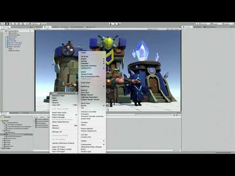
Unity Forum
Hi, I'm trying to change my legacy render pipeline based project to LWRP based and stucked for multi-pass shader.
My original shader using two pass,...
@steel notch URP is nice and all, but standard has this "code generator" thing that's called "Surface Shaders" and it's text not graph, but it has all the options and is very mature. The URP/HDRP is nice too, but it's kind of leading edge.
@steel notch Cool!
@frosty linden I'd use vertex color, or another (higher) UV. Leave UV0 for the mesh's standard UV texture mapping. But that's me, not you.
I have the actual shader code I wish to use. Found a blur shader online. I just... it doesn't work on the URP for what I assume to be this reason.
big sad
Well, if you want to extend the renderer like you link shows, maybe it could!
Otherwise look for single-pass blur in your google fu.
Unity Forum
Hi,
I have a vertex-fragment shader that use the Unity3D GrabPass functionality (it grabs the screen). And I apply my GrabPass to have a transparent...
With my incredibly limited understanding of shaders I will figure this out darn it.
Sorry if I end up asking some stupid af questions.
That's not bad, I think you're 90% there. Remember that node I mentioned for scene color node? That's probably a grabpass type thing under the hood. Or close enough. So use that instead.
This guy?
That's the dude right there! That will give you the pixel "in the background". You pass it the screen coordinates I think. I gave you a link to the doco above.
Does using Unity's 2D Renderer limit you to only using these two graphs? Can you even make custom code based shaders for it?
I tried making a standard surface shader and it had the pink
Man this seems to be an issue with the URP. I've seen so many threads now having serious trouble tackling this.
The surface shader isn't URP. It's for standard. Never mind that for URP.
But URP uses sprite renderers as I understand it. IDK what happens if you try to do one of the others.
Graphs ARE custom code. But in SG, I suppose it has custom code node, does it not?
Wait what's the step by step process I even need to do to get this effect?
Find out what's behind the quad, apply gaussian blur to it?
Ya this is unfortunately beyond me. I've tried searching for examples but I haven't found a single one that's functional in the modern day URP.
Just going to use a float in my struct for now until SG supports compute buffers 🙂
aka never 😂
@steel notch Well, let me see if I can get you started. I can't promise you I'll produce exactly what you're expecting. But since I started yapping about it, I might as well put up or shut up. And I don't shut up easily. ;)
Lemme play a bit. I haven't even messed with 2D although I've reviewed the docs, so I'll have to create a project and a sprite/quad/whatever and then a shader and see if it works. I'll work in 2019.3 since it's the most up-to-date. May take a bit, I'm juggling things.
@meager pelican I'd greatly appreciate it. Thanks and good luck braving the deep dark world of Unity shaders.
tried switching opengl to metal on iOS, because opengl is officially depricated by apple. desired shader compiler platform 14 is not available in shader blob unity
got that error. any suggestions how to start resolving this issue
to my understanding the shaders should compile just fine but apparently they don't
Hey! Any tip to make this coloramp in Unity Shader Graph?
@grand jolt Should it always start from the bottom, regardless of the cube's rotation? Or does the gradient follow the cube's rotation?
better if I can choose where it starts (The image is from Blender, as you can see there is a mapping node where I set where it starts). But in my case in the bottom its okay
@grand jolt You can obtain a gradient across an object by taking an axis of the Position node, set to Object space if you want it to follow the cube's rotation. Since the cube's origin is at it's center, it can be offset by 0.5 to obtain a gradient from 0 to 1 along the cube.
@regal stag Thx! But can you explain it? I understand taking the position. But why the Green channel? Or G its for the vertex? Also why its an add node?
@grand jolt The G channel corresponds to the Y axis of the position.
RGBA = XYZW (But positions are Vector3, so don't have the A/W component)
Okay, that has more sense
thx @regal stag
@regal stag Sorry for bothering you, but this shouldnt be red at the top and go black?
@grand jolt I'm not too familiar with the Color Mask node, it's possible that your inputs are the wrong way around though.
If you want to swap the white out for red, I would do this instead:
Yeah, I thought about that but was trying to undestand it. Ill try to search some nice tutorials 😛 Thx for your help!
Ah, it looks like the Color Mask creates a mask, based on the how close the Mask Color input is to the In input. Like, if my input is a colour from a sample texture like this, I can use a blue Mask Colour and play around with the range to obtain something like this.
Oooh okay thank you!
I thought it was another thing
Like black = invisible, white = visible
The black just means an output of 0, and white is an output of 1
Yeah, I thought it worked like the image that you use is the mask
Ah right. Yeah if you have a mask you would want to use the Lerp node instead. It interpolates between the two A and B inputs based on the T input, which in this case would be the mask.
hi guys. is it possible to auto expose sub-shader properties to the main shader? it is daunting to recreate parameters that is necessary for subgraph
@steel notch I'd greatly appreciate it. Thanks and good luck braving the deep dark world of Unity shaders.
;)
Well IDK if this will help you or not. Let's see. I was able to get the scene color node to work in URP but it didn't work (for me, but I don't usually do 2D) in the experimental 2D renderer. When using the regular URP renderer however, this SG function will sample the scene:
The custom function looks like this:
RGBA.rgb += SHADERGRAPH_SAMPLE_SCENE_COLOR(UV.xy + float2(.01, .01));
RGBA.rgb += SHADERGRAPH_SAMPLE_SCENE_COLOR(UV.xy - float2(.01, .01));
RGBA.rgb += SHADERGRAPH_SAMPLE_SCENE_COLOR(UV.xy + float2(.0, .01));

RGBA.rgb *= .25;```
That's not a very good blur, but it gives you an example. You posted code for a different one above somewhere. So however you want to do it, you can sample and average however you need to.The output was on a diamond sprite in this example with a checker background:
As a note, the Scene Color node needs the Opaque Texture option on the URP asset to be enabled, but it also has a downsampling option which could be used as a blur, assuming you don't need the full opaque texture for anything else.
@meager pelican I'll give it a try thanks. I wonder why it doesn't work in the 2D Renderer 🤔
It could be my fault in a bad setup of the experimental 2D renderer. Maybe someone else can comment on the Scene Color node and the experimental renderer with transparent sprites.
@regal stag I saw that and it was enabled. So IDK. But like I said I don't do 2D much, so maybe I f-ed it up in my setup somehow.
Unity Forum
Title says it all, the scene color node is only returning a black texture when using the 2D renderer.
Could this be the issue?
Could be. I think I tried to set it to geometry queue manually. And no joy.
I haven't been able to get it working with the 2D renderer either (I don't usually use it either). Just saying that the downsampling is an option if wanting a blur for the normal renderer.
Ya the issue is that I'm using Unity's new 2D lights, which require it :/
OK. Now it gets fun (and harder). You can make your own customization/features to the pipeline (or wait until they fix it I suppose). There's a way to inject a "grabpass" type of thing into the pipeline with custom features. Lemme see if I can find the thread/video whatever I ran across.
ooo?
Here's the thread where they beat-up grabpass functionality in the new SRP's. At the bottom of page one (for me anyway) there's a video where they show how to do a custom outline pass. However the technique might work for a custom blur too.
https://forum.unity.com/threads/the-scriptable-render-pipeline-how-to-support-grabpass.521473/
It's a little more "advanced" technique with a custom renderer feature. And I think it will work in 2D Renderer.
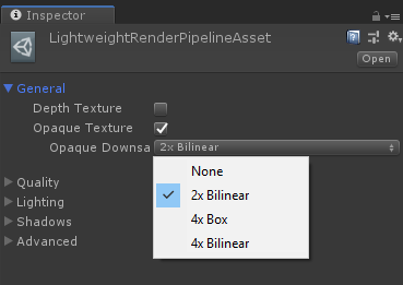
Unity Forum
I am write a custom SRP, but the game view can not deal with GrabPass. How can I fix it?
The unity report the error:
Shader properties can't be added...
But I haven't tried it.
I'm not entirely sure the video/outline example would work, as it uses the Custom Renderer Features, on the default URP renderer, which the 2D renderer replaces (and it doesn't seem to have that option in the inspector).
Crap! I thought it did. (Hence the italics I think above)
That said, Andy Touch linked a LWRPScriptableRenderPass example, which includes a blur pass which seems to inject it in a different manner, so that might work : https://github.com/UnityTechnologies/LWRPScriptableRenderPass_ExampleLibrary/blob/master/LWRPScriptableRenderPass_ExampleLibrary_Project/Assets/ScriptableRenderPasses/BlurryRefractions/BlurGrabPass.cs

GitHub
Contribute to UnityTechnologies/LWRPScriptableRenderPass_ExampleLibrary development by creating an account on GitHub.
Might just be an outdated LWRP way though, as I don't think IAfterOpaquePass is listed in the URP Scripting API.
(Yeah.. looks like it is. Guess that won't work either).
Is AfterSybox listed? That would be a good point. (I'll go follow your link...)
In LWRP, there was a IAfterSkyboxPass. Looks like it was all removed in URP, probably in favour of the Custom Renderer features on the renderer instead.
But isn't on the 2D renderer! ?!?!?!?
lol
I suppose he/they could customize the 2D renderer until there's a fix if they were so inclined. I mean it IS scriptable after all.
Yeah, it might not have worked with the 2D one anyway though.
I guess you might be able to use another camera to render to a render texture, as a sort of grab pass. Excluding certain layers using the Culling Mask.
That might not be bad in his case. OpaqueCamera and TransparentCamera. Opaque one renders to a render texture or ???uses MRT??? (IDK that that works in SG). So he might need a combo post-process pass or something???
Hey @steel notch - I'd get a clarification from Unity Answers or maybe a bug report for SG or something, and then as a temp measure just use a 25% transparent shader for your effect-sprites as a place-holder until you know if/when Unity will address this.
Do you mind just giving me a summary of the issue?
From what I understand to do an effect like this usually involved a custom pass, which the URP doesn't do by default. It has a way to add in new custom passes, but this feature is mussing from the 2D renderer.
Is that correct?
Not quite, it works in URP but doesn't work for 2D experimental renderer (that you need for your lights).
So the question is why doesn't the SG scene Color node work in the experimental 2D renderer (or it does and we don't know it).