#archived-shaders
1 messages · Page 126 of 1
I wanted a star in Unity that I could change the colors of, but I didn't feel like sitting through a tutorial to get one so I could test what it would look like.
So I grabbed a star from shadertoy and wanted to convert it
But at this point I might as well find a tutorial instead to make it from scratch in shadergraph

Here is the version in Unity 😂
On a sphere and on a plane
iChannel0 is what gives it the texture in the center
What did you replace it with?
And you can't just put a fullscreen effect on a a sphere and expect it to look right
Well I mean
I'm not criticizing anyone
Just thought I'd try and see what happens
But thanks for the help. Means I can convert shaders in the future too.
This is the texture I gave it
You should probably check what the license on the shader is
Since you might not be allowed to use it
Oh I wasn't going to keep it.
If I could use this as a prototype thing for myself so I can see what a scene could look like, then I'd be fine.
Then I could get rid of the shader and find out how to make one
@low lichen Do you know of any tutorials that uses shadergraph to make something like a star texture? Or similar?
@void bobcat Do you also want the glowing flares coming off of it?
Hmmm, I want to make something that looks more like a...er, white dwarf I think?
It produces a lot less heat than a yellow star does.
Can you show a reference picture of what you want to achieve?
Lemme look real quick
Right so, upper left corner is a yellow star like ours. Upper right is a red star, low right is a blue star (which I am pretty sure is made up) and the lower left is a white dwarf.
The glow effect will not be achieved in the same shader. It's either a separate mesh with a separate material that does just the glow or a post processing effect.
Right
In that picture, it just looks like a 2D image overlayed on top of the stars
Well that could be the case for the picture. But I'd wanna make a 3D object
That's probably true.
I want to encase the star in a dyson sphere.
But that's a separate thing
The star without the glow is very simple. Just an unlit shader with a nice looking texture with a color applied to it
It's only if you want to do something fancy like animate the surface texture that things get more complicated
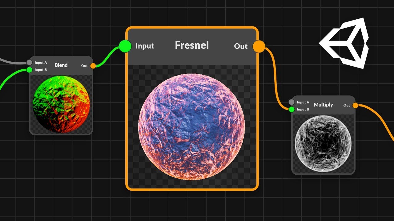
It would have to be a gradient no? From the middle and outwards. White to Blue then a texture on top with a red tint?
Doesn't look like that in the picture you posted
If you want that type of effect, you'd use a fresnel node.
And this is where you start to lose me as my shader experience is limited x)
There's a node in Shader Graph called Fresnel. This tutorial seems to go over it:
https://www.youtube.com/watch?v=Ar9eIn4z6XE
● Check out Bolt: http://ludiq.io/bolt/download The time has come... Let's explore Unity's new Shader Graph! ♥ Support Brackeys on Patreon: http://patreon.co...
alright
Alrighty, so I have changed everything over to use only rendertextures, and I changed the color space, but I am still getting the same issues. Any suggestions?
I guess the main question is, why isn't the compute buffer and the render texture behaving the same way?
Why do reflection probes do a stencil write before every actual reflection probe draw call, in unity's deferred renderer?
@ me if you know
Helloo
https://www.youtube.com/watch?v=RbCq3yDtCl0 how can i make shader like this. When car hit the ball it will spread to road

Painty Drift - New Game for Android https://youtu.be/RbCq3yDtCl0 Link to the game https://play.google.com/store/apps/details?id=com.bitesizedgames.paintydrif...
@dark flare its likely some form of masking for the pixels affected by probes
Why does it need two separate draw calls? I don't understand why it's not one pass
@uncut karma
Oh I see...
Bit #4 (value=16) is used for light shape culling during the lighting pass, so that Unity executes only the lighting shader on pixels that the light touches, and not on pixels where the surface geometry is behind the light volume.
It's not for the reflection itself, it's for the lighting pass later
Its still strange it doesn't do the stencil in the same pass
Does anyone have any suggestions about my problem?
What's the actual issue with the RT @vapid orbit?
Did you create the RT as linear, and are you sampling using a sampler or direct array access?
If using a sampler, are you offsetting by half a pixel (if using a linear sample), or try using a point sample
Just a few ideas
Gl 💤
So, I'm not exactly sure what the issue is. Also yes, I believe I changed the color space, and as far as I understand, I can't actually sample from a rendertexture, I have to use direct array access.
You can use a sampler, you just need to define the samplers manually
But if you're already directly accessing it it's probably better for fluid sim
Unless you're trying to do something clever
But save that until after it's working initially hehe
The color space is defined when you create the RT in code
If you don't define one it uses whatever the project settings are set to
I recommend linear everything but not everyone agrees
Ah, yeah I already set the color space to linear on my project settings, but I'll double check to make sure I'm not defining it to be anything else when I create the render texture
The option for linear or gamma conversion is in here, maybe to be safe be explicit
Without knowing what the actual issue is it is hard to help tho
What's happening vs what you expect
The only information that I have, is that for whatever reason it's behaving differently than a computebuffer that's being treated like a 2D array. So, what I expect to happen is that it will have what appears to be smoke flowing out of a position that I give it, however what is actually happening is well... virtually nothing, in that only a ball of grey smoke appears.
Are you trying to read and write to the same render texture? Your GPU may not support that, if so. Try double buffering
If you have a DX11.0 card (instead of a 11.1) you can't read and write at the same time
Yeah, I'm using double buffering
It's kind of necessary for this sort of thing, because it operates KIND OF like a cellular automata.
Hmm, is the result completely static? Maybe something silly like not swapping the buffers after dispatch?
Glancing at your code, are you just copying the whole RT every time? Why not just swap the references instead?
OH
Yes, don't worry I already fixed that lol
Someone else suggested that I change it to use rendertextures only instead of Texture3D
Let me push those changes real quick
Alrighty, the changes should be up on github now
This might be silly and nit picky, but I recommend finding and caching your kernal IDs manually lol
Those Dispatch(0) calls stress me tf out
Lol! It would probably be a bit cleaner if I did that
@strange onyx I guess that it's lerp functions. lerp1=textA->texB where t=noise, lerp2=texC->textD where t=noise, next lerpAll=lerp1->lerp2 where t=alpha and at the end there is multiplication (but I dont know why :P)
this is not the place to ask for support for the discord app...
with tons of parameters, things get messyyy, a way to add even like simple headers would be great
using shader graph
Could someone give me some advice on how to remap a vertex mask to the actual vertex positions of a mesh in a sprite shader? What I have here DOES work - as long as we don't use sprites from an atlas. What happens is that the vertex mask ends up getting the same pixel positions from its texture, as the sprite does from the sprite atlas. What I need to do is have the vertex mask use the UV positions INSTEAD OF the pixel positions. I'm a bit lost on how to do that in shader graph...
@remote osprey but the mask is using the UV positions, it says it right there, also that lerp could be replaced with a multiplication I think
That's what was confusing me too... it seems like it is, but the sprite position appears to be affecting it. Lemme get a quick video...
okay
Btw I also have a question, anyone knows how to get a specific world position in screen position in shader graph?
These are both using the exact same shader. The only difference is the sprite on the left comes from an atlas, and the sprite on the right is a stand-alone 'single' sprite.
Hmm, maybe unity overrides the first UV map of sprites? (I don't know a much about sprites) Maybe try using the secondary UVs for the displacement, or vertex colors, or maybe even normals
or actually Object space vertex positions should also work I think if set up properly
It's certainly something Unity doesn't like doing... we had do to some wild tricks to make this work when this was originally a shaderlab shader, lol
does it really have to be in an atlas?
okay I'll test this 🙂
Hey I got it!!
It was the object space vert positions.
Pass those in to the UV for the vertex mask
Really I should say, YOU got it @cosmic prairie !
THank you!!! I've been stuck on this for like a week.

hmm I thought they would have made sprites to be 1*1 but it turns out they are not, you might have to fiddle with numbers to get proper uvs but they should work
Yeah, I don't think they ever thought someone would treat the sprites like meshes to get vfx.
Umm so anyone knows how to convert a given world space coordinate into screen space (or back)
?
or even view to screen space
how do i set this material to draw over everything in the scene?
@grand jolt Depth Test set to Always, like the material already is, should make it draw on top of everything
Only other thing to change would be the sorting priority to make sure it's drawn last.
Is there any way to loop through an array in the shader graph?
Okay, first i need to know if you can even have an array of vector3
@kind helm You'll have to use a Custom Function node, but you should be able to use arrays & loops. I don't think you can have a float3 array though and set it correctly, as material.SetVectorArray takes a Vector4 array. It may have to be a float array, set it using material.SetFloatArray, and loop through in sets of 3. Or use a float4 array, set it using material.SetVectorArray and just ignore the last component.
e.g.
float _Points[5*3]; // 5 x Vector3s, but split into floats.
void FunctionName_float(...){
    for (int i = 0; i < 5*3; i += 3){
        float3 p = float3(_Points[i], _Points[i+1], _Points[i+2]);
        ...
    }
}```Has to be float4 array unless you use a ComputeBuffer and SetBuffer instead.
Hello everyone,
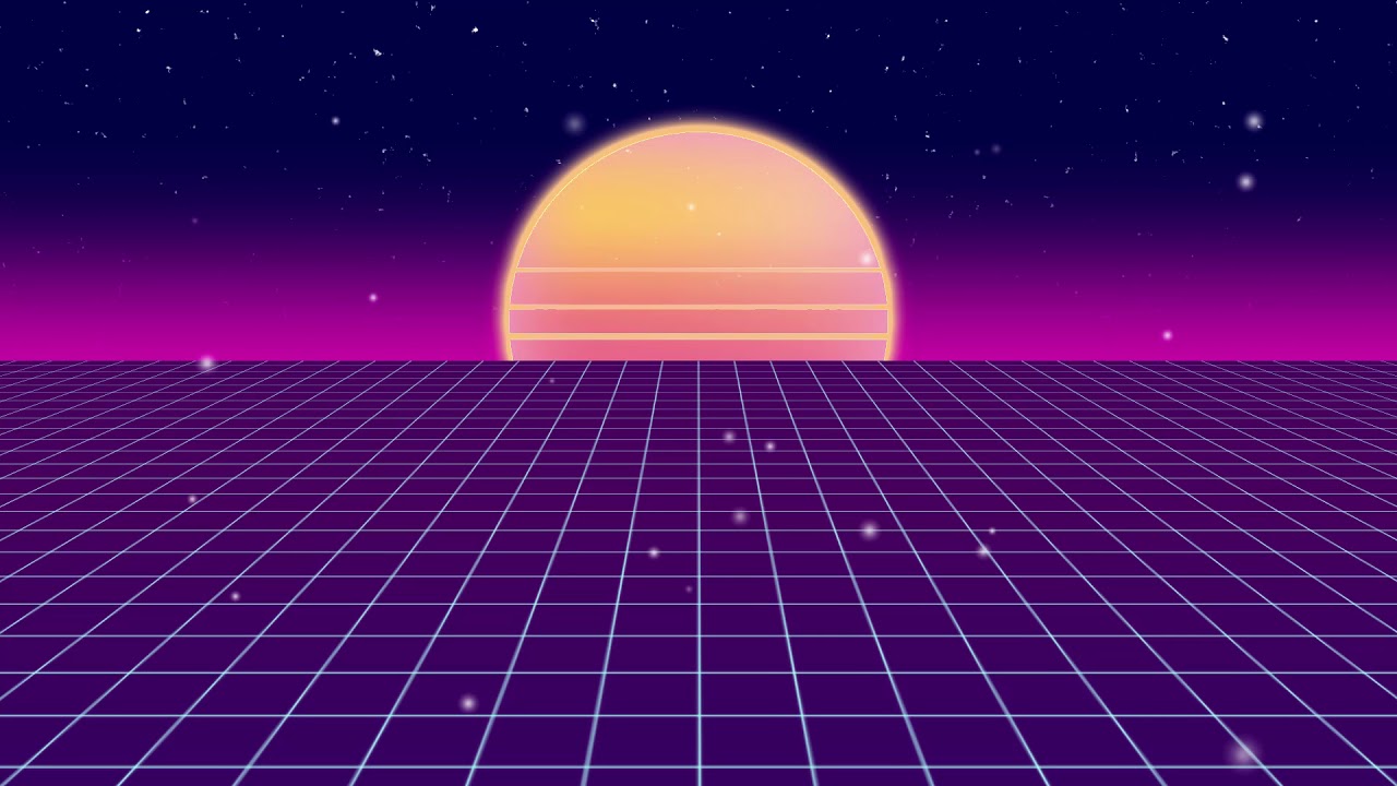
can someone point me in the right direction on how to create grid shader like this?
https://www.youtube.com/watch?v=XqKIOLvmsjw&feature=youtu.be
For Clone Hero Discord
i have the grid working, but its just vertical, and i would like it to be in perspective
Hi, I wanted a projector with an animated texture. So I created a quad with a material that is animated. I then use an orthographic camera that looks at that texture, writes to a render texture, then I assign that texture to the projector. However, I found it is incredibly slow, taking about 2 milliseconds per instance. Any tips on this?
@kind helm
I remember reading an article that float4 was an optimal size for cache coherence or indexing or whatever, even when using compute buffers.
So although I'm not sure, you might want to use a float 4 and reserve the final float for something else like some kind of flag(s). Just a thought.
@full kestrel Use something similar to this:
https://www.youtube.com/watch?v=_NfxMMzYwgo
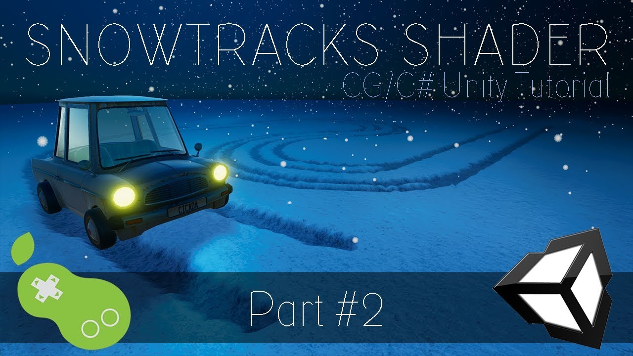
A new tutorial series on how to create a snowtracks shader in CG language, within the Unity Engine. You might want to make footprints in the sand, or snow. O...
Instead of height map you use the render target however you want
Bernard, what I am doing is different but I appreciate the link
The point of the link was for the setup of the temporary render target and using the Blit operation to draw your animated material to the rendertarget, should get rid of the whole orthographic camera and multi rendertarget
Part 4 of that tutorial might be more what you want
transparent albedo?
I think so
i just wanted doing something like that
actually, this is a force field, I just want an aura right in the sphere .. like it's those snow globes
i don't need more! ty
Hey there, how do I create a PBR Graph in Unity 2019.2.f1?
I have this shader created:
but when I save it and look at the plane I've associated the material to, it doesn't show the shader
any advice would be greatly appeciated
Looks like your default colour for the ripples being black would likely be the issue
wow so weird! It didn't update from the shader but that did the trick haha thanks
I'm still learning 😦
how does implicit float4 to float conversion works? I just realized I've been making a mistake doing most of my stuff using color instead of R channel and now when I try to fix that, bunch of stuff is broken. 😦
wait I think it convertes by taking the R channel as I needed, I probably broke it a different way
yeah it uses the r
thanks @cosmic prairie ! 🙇
why is it still pink color? my effect doesnt work or am i wrong?
@sly fossil you have SRP asset assigned in the project settings->graphics?
shader graph requires you to use some SRP (URP/LWRP/HDRP)
Does anyone know how to resolve this?
WARNING: Shader Did you use #pragma only_renderers and omit this platform?
WARNING: Shader Unsupported: 'HDRP/Lit' - Pass 'DistortionVectors' has no fragment shader
WARNING: Shader Unsupported: 'HDRP/Lit' - Pass 'TransparentDepthPrepass' has no fragment shader
WARNING: Shader Unsupported: 'HDRP/Lit' - Pass 'TransparentBackface' has no fragment shader
WARNING: Shader Unsupported: 'HDRP/Lit' - Pass 'Forward' has no fragment shader
WARNING: Shader Unsupported: 'HDRP/Lit' - Pass 'TransparentDepthPostpass' has no fragment shader```Does anyone have a sample billboard shader graph?
wont work :/
How can i sample a texture 2d in custom expression (Shader Graph HDRP), I'm getting this error https://prnt.sc/pllc52

Yo guys, is there any way to get a good shadow distance going in LWRP without it ruining the shadow quality when you're close to them?
shadow distance 80 and at about max distance from it
shadow distance 500
cause I want shadows at a reasonable distance, not just 3 foot away, but I also want them to look better the closer you are to them
shadow cascades?
@north karma I have a same issue, found on forums that Custom Function does not support Conversion from Texture2D to Sampler, same as Unreal didnt back some time
is anyone familiar with this error from ProcessingStack v2? Shader error in 'Hidden/PostProcessing/MultiScaleVO': failed to open source file: '../StdLib.hlsl' at line 9 (on d3d11)
I tried removing it and reinstalling multiple times from the package manager with no luck
@little dew what are you using it with?
2019.1.6f1
@merry rose you can run samplers on custom function
@little dew you have the old asset store version installed?
not that I'm aware of, no
also you are using it with built-in renderer, LWRP or HDRP?
HDRP doesn't support PPv2 anymore on 2019.1
also if it's not HDRP, then make sure it actually installs the latest version for 2019.1
it doesn't always do that by default
instead it can default to the verified package which can often be a lot older
yeah I checked the package info and says 2018.1, might be that maybe
how can you do it? It always shows same error, tried almost every version of unity or HDRP, the thing is always giving me error
@merry rose there are shader macros you can use, I can't remember them out of my head tho
altho it says 2019.1 verified 🤔
you mean this https://docs.unity3d.com/Manual/SL-BuiltinMacros.html ?

yeah, I don't remember if those worked as is for sampling on HDRP but I'm pretty sure I did this thing a while back
@merry rose what are you trying to do with these?
I am trying to do parallax occlusion mapping, I made parallax mapping but for the more sampled one I need to do a loop and that only works with custom functions, they should add a loop node maybe 🤔 😄
@merry rose there's a POM node on newer HDRP already
I can't remember when they added it tho
I know but when you use it you cannot lerp between two of them, only one can be used at a time, so for terrain shader that does not work
you can't make a true terrain shader with shader graph either
if you use it on a mesh, then that's doable
I cant even lerp POM on anything, I tried on custom meshes, the UVs are broken, it gets the first parallax effect and uses it on everything
but I actually made my own terrain shader, looks nice, but yeah its not instanced, I have to look into that
@fervent tinsel So I am looking into it, learned about it for what 6 hours now and got the first thing working 😄 , you can use SAMPLE_TEXTURE2D(textureName, samplerState, UVs) to sample a texture fuuu 😄
sounds about right
you coud probably use the sampler node too
unless you insist of doing it all on custom code
I can't remember if subgraph fixes has been backported to 2019.1 but that's the way to do complex graphs now
basically you stuff most of the logic in subgraphs and use custom function thing for things you don't find nodes for
I have an issue with a material I don't understand
This wall is supposed to emit blue
And it does when I'm not in playmode
As soon as playmode is turned on, it goes purple
What am I missing about Emission here?
I'm using Universal Render Pipeline
Didn't change any default settings on it
You need gi
Is that a setting I need to use or something I need to put on a light?
@merry rose @fervent tinsel So, how did you managed to just do a simple sample texture in a Custom Expression node? I need to loop through texture (array of positions written into RGB), so I need sample and modify the UV of the texture inside Custom Expression node. https://prnt.sc/pllc52
Sadly, but SG HDRP does not support arrays as a variable.
basically it should go like this for you: tempPos = SAMPLE_TEXTURE2D([Texture2D], SamplerAffectorsCE, tempUV);
Is there a way to duplicate the effects of the Gradient Noise Node in C#?
IE Plugging some vector2 and a Vector 1 into the script and getting an identical output to the Gradient Noise Node seen in shader graph
@merry rose Same error 😦
@north karma you can't create SamplerState inside, add it as input
@merry rose Thx, it worked 🙂
Or alternatively, get the gradient noise, or a custom node, to function identically to the C# Mathf.PerlinNoise(float * Scale, float * Scale)
Hey guys. I've got this starfield shader im working on and i wanted to have a flickering texture. What i did was having a moving simple noise moving multiplied on a speckle texture but for some reason it's just making the emmisive dark in the area with those speckles
this is it without the flickering ones
here's how it looks with the "flickering"
it isnt flickering though, as i said. It's just showing those dark spots
actually, just noticed. It is flickering. However, it's flickering where it goes from black to the blue speckle color then back
what i want is for the star to be transparent except for when it occasionally flickers
i hope i explained this well enough
Looks great!
Thanks, it’s real simple though. I just need help with that one issue
@merry rose Sorry for bothering you again, but this one is complicated. For some reason when I plug the output into the Position this error appears
This only happens in a Position input and when the texture is sampled in a Custom expression.
is it possible to apply a one shader operation to the previous operation in full? I want to process an image and then process that result for a few iterations.
Fixed it by using the SAMPLE_TEXTURE2D_LOD
or let me put it another way, is it possible to sample the pixels of a previous pass in a shader?
@north karma yeah, that makes sense, basic SAMPLE_TEXTURE2D is not not working on vertex level, so it cannot change vertex position, the LOD one does
@worthy ridge try RenderTextures
@merry rose yeah, I was going to say about the SS
also I do recommend using the file approach instead of the embedded text as it's easier to work with
Yeah, i use file, it can get a bit messy 😅
Hey guys, is it possible to know which part of the texture you're touching with shader graph?
It's not really clear ... how would you like to do that ?
It depends on the UVs you're sendign to the sample texture node.
@amber saffron I'm trying to make a selectable grid. But i have no idea which node to use.
Oh okay, got it.
You can't do that with purely shader graph
You'll need to find the coordinate of where you're touching the grid, and then send it to the shader from c# code
how do i update the texture/coordinate of it?
idk how to pick a coordinate and affect that part of the texture.
Search how to do Raycasts in c#, you'll be able to get the UV coordinate you're touching : https://docs.unity3d.com/ScriptReference/RaycastHit-textureCoord.html
You can then pass it to the material using https://docs.unity3d.com/ScriptReference/Material.SetVector.html
And in the shader, use it as a mask
Or you can also directly change the texture using https://docs.unity3d.com/ScriptReference/Texture2D.SetPixel.html
use it as a mask?
Yes, you can take the input coordinate to build a mask in the shader to display something else instead of the texture for example
but since I don't really know what your final intention is, I'm only throwing ideas here.
I want to be able to make a node change color when i select a node in that coord in script
I'm currently using IPointer. Am i still able to use this or i need to change to raycast?
public void OnPointerClick(PointerEventData eventData) {
            OnClickEvent.Invoke(eventData.pointerCurrentRaycast.worldPosition);
        }
You can use an other method, I suggested raycast because it's easy, but the idea is to transform the cursor position to a data that can be used in the shader.
Okay
I will try it first. Thanks alot!
@amber saffron So what you're trying to say is i can clip the main texture with this method? https://www.febucci.com/2018/09/world-reveal-shader/

Learn how to fade/dissolve all the objects in your game if they're too far (or near) from the player. We'll use HLSL and Unity's Shader Graph.
Yep, something like that
Alright thanks alot!
@steel kayak most wouldn't make that kind of thing in a single shader
instead just move a selection quad where player selects the thing
(maybe I misunderstood the intent here)
im able to build but i need a grid repressentation for the grid. those gray boxes are gizmos.
i select nodes by using the position i get from hitiing the plane
so i was thinking whether i could make the plane into like vr grid(?)
if you guys have any tutorial series that has similar concepts, let me know please. I'm willing to learn.
I bet most would just have each object to have selection quad in it and then enable the renderer on demand when selected etc
if you'd want to be more efficient, then have a pool of selections somewhere and move things into sight from there
(if you need multiselection)
again, I may totally miss what's the intent here
Ohh i see what you mean. The plane above should be holographic grid.
How can i create shader, which hides all UI in object with him?
I'm trying to add noise to a shader, and gradient noise works fine, but I need it to align with a scipt, so I can't use that. Likewise, mathf.perlinnoise does what I need, but I can't call it in shader.
you can expose any parameter in the shader and you can change those via a script
Sorry, I don't know what you meam
My shader settings are already controlled by script, which ensures it's values are synchronized with my other scripts.
But I need to pass a position node through a function identical to the functions in my c# script, and the shader functions don't contain the same noise functions as c#
hey guys. Say i have this code

Gist
Flow Map Shader for Unity3D. Used with Sprites. GitHub Gist: instantly share code, notes, and snippets.
and i wanted to import it so that i would get a graph like it
how would i do that?
i mean get a node like that, not a graph
does anyone know why a vertex shader would be broken by static batching?
I'm getting bizarre behavior where instead of moving vertices outward by v.normal they seem to move in a random direction instead
looks fine in scene view, only happens when you start running the game
how can I get the world position of a pixel in the fragment shader? I tried to use this:
output.worldSpacePos = mul(unity_ObjectToWorld, float4(input.vertex.x, input.vertex.y, input.vertex.z, 1.0));
But then in my fragment shader I'm displaying the X position:
return fixed4(0.0f, input.worldSpacePos.x + 0, 0.0f, 1.0f);
And it's half green at (0.0), starts to get green at around (30, 0) to the right, and starts to get black at around (-30, 0) to the left.
@wet geode what is a "node like that" ?
I'm trying to apply the output of a shader on top of itself 3 times each frame.
would graphics.blit help me do this?
im doing recursive image processing,
@worthy ridge that's actually what I'm currently trying to do, unsuccessfully though. I'm trying to use the render texture as both source and destination.
It does output the shader, but I can't get it to get the source texture value from _MainTex. I might be doing something wrong though
@ocean geyser what I'm doing now is simply using two render textures
@ocean geyser i load a texture into one RT1 using graphics.blit and then process RT1 with RT2 as the destination
@ocean geyser then i repeat the other way, process RT2 into RT1 using graphics.blit
I don't know if this is bad practice or whatever, but it seems to work in an update loop for some realtime image processing
I actually just tried to use an extra texture rather than a single render texture, that also work.
Your process is also fine - but doesn't it also mean you need to change the texture you're using every time? from RT1 to RT2 and vice versa?
yeah, i swap source and destination every time i want to run my shader again on its result
im guessing you can't read and write to a RT at the same time
no I'm not talking about the processing it self - I'm talking about the usage of it.
You're doing recursive image processing - what happens when you're done with the processing?
In my case for example I'm drawing the end result, meaning I need the result to be attached to a material.
If I did it your way, I would also need to call renderMaterial.SetTexture("_MainTex", RT1); , and sometimes RT2.
and yeah you can't read and write to an RT at the same time, but you can use 1 render target + 1 texture.
Process the texture into the render target, then copy the result back to the texture.
I'm only looping a pixel errosion shader over and over a few times each frame in Update() before displaying the result in the gameview
why would i need to call SetTexture?
how are you displaying it in the gameview?
pretty simple, i just have my RT's defined in the project and have assigned one of them to the materials albedo map slot
right. But that slot accept a single texture. Which RT did you assign to it? RT1 or RT2?
RT2. It since it's the one used last in my code.
Well you're doing it multiple times in a single update, so I guess in your case it's not really an issue. I'm doing it once per frame
anyway it works for you now then?
yeah it does
there is mention of this sort of technique here https://catlikecoding.com/unity/tutorials/advanced-rendering/bloom/Bloom.pdf
including RenderTexture.GetTemporary
Yeah I saw that when googling, didn't like the idea of it though. I much prefer to have a constant extra render target/texture, assuming it's only 1. That's just me though.
Any chance you could help me with the world position issue I'm having btw?
@ocean geyser that world space stuff looks right to me, assuming input.vertex is in object space
Alright, so, I'm converting the Shader Graph node Gradient Noise from HLSL:
float2 unity_gradientNoise_dir(float2 p)
{
    p = p % 289;
    float x = (34 * p.x + 1) * p.x % 289 + p.y;
    x = (34 * x + 1) * x % 289;
    x = frac(x / 41) * 2 - 1;
    return normalize(float2(x - floor(x + 0.5), abs(x) - 0.5));
}

float unity_gradientNoise(float2 p)
{
    float2 ip = floor(p);
    float2 fp = frac(p);
    float d00 = dot(unity_gradientNoise_dir(ip), fp);
    float d01 = dot(unity_gradientNoise_dir(ip + float2(0, 1)), fp - float2(0, 1));
    float d10 = dot(unity_gradientNoise_dir(ip + float2(1, 0)), fp - float2(1, 0));
    float d11 = dot(unity_gradientNoise_dir(ip + float2(1, 1)), fp - float2(1, 1));
    fp = fp * fp * fp * (fp * (fp * 6 - 15) + 10);
    return lerp(lerp(d00, d01, fp.y), lerp(d10, d11, fp.y), fp.x);
}

void Unity_GradientNoise_float(float2 UV, float Scale, out float Out)
{
    Out = unity_gradientNoise(UV * Scale) + 0.5;
}
to C#
Vector2 gradientNoisedir(Vector2 p)
{
    p = new Vector2(p.x % 289, p.y % 289);
    float x = (34 * p.x + 1) * p.x % 289 + p.y;
    x = (34 * x + 1) * x % 289;
    x = ((x / 41)%1) * 2 - 1;
    return (new  Vector2(x - Mathf.Floor(x + 0.5f), Mathf.Abs(x) - 0.5f)).normalized;
}

float gradientNoise(Vector2 p)
{
    Vector2 ip = new Vector2(Mathf.Floor(p.x), Mathf.Floor(p.y));
    Vector2 fp = new Vector2(p.x%1, p.y%1);
    float d00 = Vector2.Dot(gradientNoisedir(ip), fp);
    float d01 = Vector2.Dot(gradientNoisedir(ip + new Vector2(0, 1)), fp - new Vector2(0, 1));
    float d10 = Vector2.Dot(gradientNoisedir(ip + new Vector2(1, 0)), fp - new Vector2(1, 0));
    float d11 = Vector2.Dot(gradientNoisedir(ip + new Vector2(1, 1)), fp - new Vector2(1, 1));
    fp = fp * fp * fp * (fp * (fp * 6 - new Vector2(15,15)) + new Vector2(10, 10));
    return Mathf.Lerp(Mathf.Lerp(d00, d01, fp.y), Mathf.Lerp(d10, d11, fp.y), fp.x);
}

void Update()
{
    UV = somevector2;
    Outputt = gradientNoise(UV * Scale) + 0.5f;
}
For some values, my converted function is spitting out identical values to the source HLSL function, but for others it's spitting out either totally unexpected values, or just out of sync values. Did I convert it wrong?
i think x%1 might be different behavior from frac(x)
try makingfrac(x) to be x - floor(x)
ok let me try that
x%1 i believe can be negative but frac can't
If that's the case, that's probably it
yea looks like it is the case
but wait, wouldn't x-Mathf.Floor(x) potentially spew negative
Hmm, that's fixed the absurd artifacts
i'm also thinking maybe the modulo in unity_gradientNoise_dir acts differently in C#
not sure how to fix that one though
hlsl docs say The % operator is defined only in cases where either both sides are positive or both sides are negative. Unlike C, it also operates on floating-point data types, as well as integers. https://docs.microsoft.com/en-us/windows/win32/direct3dhlsl/dx-graphics-hlsl-operators
Expressions are sequences of variables and literals punctuated by operators.
Yeah, I'm still getting some out of sync values
maybe try ```
float mod(float x, float y)
{
return x - y * Mathf.Floor(x/y)
}
as a % replacement you mean
yea
that made it worse
wait, I might be breaking order of operations...
@last robin I'm still seeing some out of sync values, but I think we've almost got it dialed in
the only other thing i can think of trying is float mod(float x, float y) { return x - y * trunc(x/y) }
I'm not sure if % is the same as fmod but that's what fmod does
i'm also not sure how to translate trunc
maybe that's just x - frac(x)?
there is Math.Truncate but no Mathf.Truncate
maybe (float)Math.Truncate((double)x/y)
🤷
I'mma try swapping out my Mathf.Lerps for Vector3.Lerps
ahh it doesn't wanna do that...
hi all. Got a lil problem here. When I import VRML files into Unity, they can be visualized thanks to a shader I found online. Vertex shader for 3D Pipeline... But, this shader does not work for the HD pipeline. Does some one knows how to make it work?
Supposedly casting to int also truncates numbers, so a supposed mathf.truncate(float) is the same as (int)(float)
@uncut karma yeah it is. At least it looks like
This is how it looks with output.worldSpacePos = input.vertex;
then again, it's also how it looks with
output.worldSpacePos = mul(unity_ObjectToWorld, float4(input.vertex.x, input.vertex.y, input.vertex.z, 1.0));
It's like unity_ObjectToWorld is an identity matrix. Not sure why that would be
you can just do mul(unity_ObjectToWorld, input.vertex); btw
or even float4(input.vertex.xyz, 1.0) if you want to change the w for some reason
ha .xyz is nice. I'm using float4(input.vertex, 1.0f) rather than input.vertex btw because that is what I saw in the unity docs.
But neither one is working actually.. they don't result in world space coordinates, that is
ya i'm not sure why that would be the case unfortunately
mm unity_ObjectToWorld should be the same as transform.localToWorldMatrix; right?
i believe so
well I just tried to using it manually instead.
It "almost" works. It does seem to change when I'm moving the object, hence represent world space coordinates, but 0 is seems to be actually -74.
What is going on..
are you able to post the code that you're using unity_ObjectToWorld in?
would be easier to see what's wrong
ha the shader actually works on a "clean" object.
I think the problem is because I'm trying to use Graphics.Blit(). I guess I need to push some matrices my self in there
yeah sorry, I didn't think it matters. I was the single line Graphics.Blit for some time now and it all looked the same, didn't even cross my mind.
I'm a bit confused though. The examples I found in the unity docs either use Graphics.Blit or GL... functions but without Graphics.Blit()
Any idea how to combine them properly?
can you link what docs you're looking at? Not sure
Graphics.blit: https://docs.unity3d.com/ScriptReference/Graphics.Blit.html
GL.LoadOrtho: https://docs.unity3d.com/ScriptReference/GL.LoadOrtho.html
The examples in them, to be precise.
oh just use Material.SetMatrix for passing a matrix
and then you can get whatever matrix you need from the camera or from the object
oh just do it my self then, ok. I got that piece of code already
well it still doesn't work correctly; as said it's world space coordinates, but with an offset (0 is -74 or so).
I did found this in the docs for transform.localToWorldMatrix:
IMPORTANT: If you're setting shader parameters you MUST use Renderer.localToWorldMatrix instead.
What renderer is it talking about though?
ok nvm, that's not the issue. I'm having scale on the object, and removing the scale fixes it. I'll try to look into that, but it looks like the solution.
Ok it seems to work now. Thanks for the help @last robin !
@last robin I think I fixed it. Rather than perfecting my translation from HLSL, I just took what I had and translated it back to HLSL
I'll have to test later, because it's 4AM and I need sleep, but either way you was a hugehelp
Hey guys, how do you mask using texture like this? This video doesn't teach me and i can't seems to find any about shader graph.
https://www.youtube.com/watch?v=UzQtWyK4M2Y

This is Multi Color Mask Shader I made via shader graph within Unity 2019.1.0f2 LWRP Template. You can apply any count of materials you want on the model and...
Hi! Is there an easy way to create a Lit Shader with fuzz in the shader graph, like in Marmoset?
Or perhaps any documentation on the fabric node
@steel kayak Nice idea, but I'm looking for something with the fresnel node!
Probably
Does anyone have a snippet for creating a billboard that faces the camera?
in standard shader code (not shader graph)
Any way to make a Quad face always the camera with PBR graph?
@oak latch This might help
https://answers.unity.com/questions/1621611/how-to-do-billboard-shader-with-shadergraphhow-to.html
Unity is the ultimate game development platform. Use Unity to build high-quality 3D and 2D games, deploy them across mobile, desktop, VR/AR, consoles or the Web, and connect with loyal and enthusiastic players and customers.
Hey everyone, I am trying to get the main light shadows in shader graph using this : https://blogs.unity3d.com/2019/07/31/custom-lighting-in-shader-graph-expanding-your-graphs-in-2019/
But it seems that it doesn't work in 2019.3.0b7 or am I missing something ?

Unity Technologies Blog
With the release of Unity Editor 2019.1, the Shader Graph package officially came out of preview! Now, in 2019.2, we’re bringing even more features and fun...
I would be interested in this sample converted to 19.3b and HDRP, was looking at it just today. Just learning things…
that sample project is only officially supported to work on 19.2 right now
Alright
that's my project haha unfortunately do not have the time to update and maintain it
That's strange because if I look at the github repository, function called are the same.
it might work but like i said, it's only officially supported for 19.2
other things unrelated to it might break ¯_(ツ)_/¯
Yup I understand 😉
@stone sandal no need to maintain, just update it once to HDRP 19.3 🙂 That would work for me 🙂
@stone sandal I found a way to get shadows on the main directional light (just to let you know)
float4 shadowCoord = TransformWorldToShadowCoord(WorldPosition);
ShadowSamplingData shadowSamplingData = GetMainLightShadowSamplingData();
half shadowStrength = GetMainLightShadowStrength();
Shadow = SampleShadowmap(shadowCoord, TEXTURE2D_ARGS(_MainLightShadowmapTexture, sampler_MainLightShadowmapTexture), shadowSamplingData, shadowStrength, false);
Hi, I made a grid system using GL and Shader's
but my Grid is always drawn over everything, even my UI
I can't find on internet how I can draw my grid underneath everything but my background image
here is my code
@tardy jolt What object is this shader applied to? A plane on the ground?
Is there a way to change a master node/shader lighting model in Shader Graph? For example, from lit to unlit.
@sand tartan I’m actually a dev for shader graph , I’m well aware how to get it working, just haven’t been able to update the blog c:
@stone sandal Oh alright cool !
I can create a Lit Master node inside a Unlit Shader Graph, but I can't delete the original Master node.
Maybe it might help someone else 😉
Also I use 0 pass no idea if it have something to do
@tardy jolt So this is in orthographic view? If so, the Z position, which you seem to be just setting to 0, will determine if it renders over other objects.
It is yes
I tried changing z pos
It didn't change anything sadly
My camera is at Z -10
My line is at Z 1
@tardy jolt When are you calling the GL functions?
"void OnPostRender() {"
Have you tried OnPreRender instead?
@tardy jolt This simple example is working for me. The line is rendered behind objects in front of it:
private Material _material;

private void Awake()
{
    var shader = Shader.Find("Hidden/Internal-Colored");
    _material = new Material(shader);
    _material.hideFlags = HideFlags.HideAndDontSave;
    _material.SetInt("_SrcBlend", (int) BlendMode.SrcAlpha);
    _material.SetInt("_DstBlend", (int) BlendMode.OneMinusSrcAlpha);
    _material.SetInt("_Cull", (int) CullMode.Off);
    _material.SetInt("_ZTest", (int) CompareFunction.LessEqual);
}

private void OnPostRender()
{
    GL.PushMatrix();
    _material.SetPass(0);
    GL.Begin(GL.LINES);
    GL.Color(Color.red);
    GL.Vertex3(1, 1, 0);
    GL.Vertex3(-1, -1, 0);
    GL.End();
    GL.PopMatrix();
}
I try thank you
@low lichen what are pushmatrix and popmatrix for ?
also it doesn't work as well
I must have done something wrong
@tardy jolt As I understand it, it saves the current camera matrix and Pop restores it, in case you modify it I suppose.
@tardy jolt Are the elements you want drawing on top, sprite renderers and UI elements?
They are not
I have
My camera > Z -10
My game elements > Z 0 > Sorting Layer : game
My UI elements > Z 90 (can't change it) > Sorting layer : UI
The GL lines drawing > Z 0
and here are my sorting layers
How are the game elements drawn? With a sprite renderer?
It's something to do with sprites
I tested with 3D objects. With sprites, I'm also seeing the same thing as you
okay but why is it still over the UI ?
Or actually, it's because of transparency
Surely your UI needs transparency though?
The problem is that transparent objects don't write to the depth buffer, so when the line is drawn after everything, it's testing against the depth buffer, which the transparent objects aren't on
ah
So the lines have to be drawn after opaque objects but before transparent objects
how can I achieve this ?
But it should also be fine to draw the lines before opaque objects, as long as you have the lines ZWrite
I thought OnPreRender would have done it, but I guess it's not ready to start drawing at that point
seems so
I'll try some stuff, see if I can get it to work and let you know
thank you very much 
I just spent 3 hours writing a grid system in 2D and I can't get this to be drawn behind !
@tardy jolt I figured out one way to do it, but it's a little ugly because it requires an unnecessary Graphics.Blit, but it works. This is assuming you're not using LWRP/URP or HDRP:
[ImageEffectOpaque]
private void OnRenderImage(RenderTexture src, RenderTexture dest)
{
    Graphics.Blit(src, dest);

    // Your GL code goes here...
}
oh thank you so much !
it's working @low lichen
I can draw a background behind it @low lichen ?
@tardy jolt Yeah, that should work. Does it not?
hum I'm not sure how to proceed
I just drag and dropped an image into the editor and set the sorting layer to background
How so?
this is what I get when setting line start to z 50 and end to z -50
and when setting it to 0
Is that not it just clipping outside the far plane?
I think so
What is your camera's far plane set to?
That's got nothing to do with whether it writes to Z
far plane is the Z ? It's -10
oh okay
maybe I could use something else than line ?
why are we getting so much trouble just to write some lines in background ><
I think the image effect workaround is the problem. It's losing the depth buffer in the blit process.
Is the background just a solid color?
It's probably going to be an image
or a procedurally generated image
like, can't we draw the image using GL before drawing the lines ?
I mean, sure, but that's not going to fix other depth issues
I don't have anything but the background behind the grid
everything else is in front of the grid
I assume the grid is always going to be uniform, right?
You're never going to skip a line or have crooked lines?
The size of it?
Depending of the zoom it changes
Right, that should be doable without GL lines
let me send you my code so that you can see
It would reduce draw calls as well
hey guys, trying to make an animated UI image. Just want it to scroll infinitely. Problem, i can't get my shader properties to show in the inspector:
I'm drawing a quad a bunch of times using Graphics.DrawMeshInstanced to connect vertices (the quads are stretched to look like lines). Is there a way to get the quads to cylindrically billboard towards the camera in a shader similarly to the line renderer? As you can see, the quads have a fixed alignment and it doesn't look great. The quad mesh sits on the xz plane and is rotated/scaled to connect points.
guy told me to go here
anyone know how to make a projectile that leaves a decal on a mesh that shortly fades away. specifically for vrchat
@next sinew it says you're using a material based on hidden/cloudmoving
and not UITextureGraph
your shader graphs are located under Shader Graph/
should look there I think
@tardy spire it would take some math, I don't know exactly, but mainly a cross product.
You need a way to identify the 2 verts at each end of the quad (could use vertexID and modulo or bitwise operators), you probably also need to know the "side" of the line as well (for flipping the tangent vector when creating the line's width).
You'd need the start and end of the line (that the quad is meant to represent), that line as a vector with the vector to the camera can be used to create a tangent, then"spread" each of the 2 verts of the quad outward (2 from start pos, 2 from end pos) along the tangent creating the width of the line
Hi, does anyone of you know a good solution to drawing thick line segments with proper end points? Right now, I simply create a GL_LINES mesh and draw
you can probably ignore the miter join... but it illustrates the general idea
Hello, I'm really a noob in shader, but yesterday I succeed to use the LWRP/Particles/Unlit shader for a distortion effect (yeah!), now I would like to access to the Advanced/Distortion/Strength (param of the shader) dynamically on my code is that possible? If anyone can highlight me it would be great 🙂
How to multiply the uv node before texture sampling in the shader graph?
ok for some reason my uv node didnt have an output port, but i deleted and created a new one and it has one now.
for those that dont believe
Is there any docs that talk about the difference between Unlit, PBR and VFX shader graphs?
@uncut karma thanks a bunch. I'll look into it and see what I can come up with
Hey guys, how do i hook up perlin noise in the shader graph in order to make my texture tiling look better?
the perlin noise node accepts a uv vector and returns a float, where do i use that float?
@kind helm Here maybe ? : https://docs.unity3d.com/Packages/com.unity.shadergraph@6.9/manual/Master-Nodes.html
It's still missing the VFX one
@stark urchin It's not very clear on how you would like your noise to make tiling look better...
@amber saffron turned out the term for what i wanted is "seamless texture". This is how they do it path of exile http://www.pathofexile.com/forum/view-thread/55091

Path of Exile
Path of Exile is a free online-only action RPG under development by Grinding Gear Games in New Zealand.
@devout quarry you nailed it fam! Thx
@stark urchin That's not a shader thing. It's a "how to author seamless textures in a photo editor" thing.
There's a quick trick you can use depending on the texture: Cut it into 4 equal chunks and exchange the four "corners" diagonally. Swap Upper left with lower right, etc. Then you clean up the seams in the "cross" across the middle. It will tile. But it's not a "shader trick", pass the resulting texture into the shader. ONCE.
@meager pelican I get what you are saying but I don't have an artist and giving a chance to my artistic instincts will result in me dying of hunger. Luckily, it turned out there is an algorithm for creating procedural stochastic textures by tiling and blending and it works awesome! https://eheitzresearch.wordpress.com/738-2/
Procedural Stochastic Textures by Tiling and Blending Thomas Deliot and Eric Heitz GPU Zen 2 (to appear) Abstract This chapter provides some simplifications and practical details that address the f…
Cleaning the seams in the cross is not part of what a shader does?
I mean if you want to do it at runtime
and turns out this guy works for unity and has created a package and custom shader graph node for it
arent i lucky?
Sure. Gimp can create textures for you too if you want. Some of the "noise" types have a "tileable" option. It all depends on what you want...real pics or noise.
You can find many on the net too. Or use that package.
@kind helm Shaders "do" what you program them to do, but normally you don't want to compute all that stuff each frame for each texture. If you can do it once while generating/making the asset, do it once and be done. Don't make the poor GPU do it every frame for all time. The drudgery! The drudgery! The horror! 😉
@stark urchin That's a pretty impressive blog he has. (eheitzresearch)
@kind helm EDIT: But it's OK to use a GPU to generate the art asset AND THEN SAVE IT OFF to a texture for use in a game. 😉
Hey, anybody knows why 2019 ommited built-in shader overrides by name? https://forum.unity.com/threads/2019-2-overriding-shaders-of-terrain-grass.725294/
Is there any workaround?
Unity Forum
Hi!
For my project I'd like to modify the shader that is used to render the grass-meshes that I paint on the terrain with the Unit tools. However,...
@meager pelican sadly, i cant make it work, i get errors, im using 2019.3 beta
see what is says
This version is distributed here as a custom package containing ShaderGraph 6.7.1 entirely, with our added code. It requires using Unity 2019.2 or later, and a project that has either the LWRP 6.7.1 or HDRP 6.7.1 package installed. Make sure to update your render pipeline package to that version in the package manager.
does this mean that it works only with shadergraph 6.7.1 or this and above
im using 7.1.2. It's weird how the whole shader graph code is copied just because a custom node is added
also the manifest file, i need to add this line to it:
"com.unity.shadergraph": "file:../procedural-stochastic-texturing",
IDK, I can't even see the errors.
Do a google search for some free ones, check the asset store, or "exercise those art skills". Otherwise IDK what to tell ya. Good luck. Art is one of the hardest parts of game dev (it's all hard, in a way). That's why there's often more artists on a game than any other discipline.
im gonna try to fix it first, worst ill end up buying textures, so not a big deal.
@stark urchin yes it only works on 6.7.1, you might be able to copy only the custom code to 7.1.2 if the shader graph api hasn't changed, but you still must use a custom copy of 7.1.2 because you will lose changes if modifying a package directly.
@uncut karma got it, ty.
is it possible to import blender made shaders into unity?
@brazen kernel Sounds pretty impossible.
Guys, can someone check if he has Blit option in the forward renderer? I have only Render Objects and the youtube tutorial I'm watching has also Blit and something else.

Download the full example here: https://ole.unity.com/toonoutline Just the two shaders alone: https://ole.unity.com/toonoutlineshadersonly
All these toon sharers only support one light source.
why dont i have the custom function node in unity
shadergraph is up to date
i'm using lightweight RP
@wet geode is your Unity version up to date?
it might say lw rp is up to date because for that version of unity it is
@cosmic prairie hmmm apparently i wasnt up to date. Its weird because im sure i checked a few days ago and it was
weird, I never trusted the package manager, it was super buggy when I started using it, it seems to be usable now tho 🙂
Hi! Can anyone point me in the right direction for how to generate geometry or instances of geometry on surface with Shader Graph?
Like generating grass
From an existing set of prefabs or meshes
Hi everyone. How convert stencil buffer from shader to shader graph ?
Ronja's Shader Tutorials
Summary The depth buffer helps us compare depths of objects to ensure they occlude each other properly. But theres also a part of the stencil buffer ...
@alpine cliff sg doesnt support stencils atm
You'd need some custom code to access them
What is custom code means? Is that custom script code from c# or custom function in shader graph?
I think custom shader code, since you need a pass for rendering to stencil buffer I think? or can you render to stencil buffer from just any pass? If so you can use custom function
most likely means custom modifications to the SRP itself
no idea if you mean URP, LWRP or HDRP tho
in HDRP I had to modify the HDRP code itself to get stencil data (but I didn't expose it myself to SG either)
the main issue is getting the access to the buffer
I have no idea how this even happens on URP/LWRP tho, I've only played with this on HDRP
Hey guys, I just updated to Unity 2019.3 and now my shaders which I build with shader graph get errors like "redefinition of 'unity_Builtins2Array' (UnityInput.hlsl:114).
Does anybody can give me hint what is wrong or how to fix it?
@fervent tinsel I am currently learning this video.
https://www.youtube.com/watch?v=xkcCWqifT9M&list=PLFt_AvWsXl0dohbtVgHDNmgZV_UY7xZv7&index=3
In this video, he use stencil buffer via shader. But i am using URP and there is no way to use shader direct like him. So if possible, i wanna know how could i make same thing like video via shader graph in URP. and if not what should i do?

In this bonus episode we create a stencil shader to achieve a cool limited FOV effect. Source code: https://github.com/SebLague/Field-of-View Some links abou...
I don't really know how stencils work on URP, but you may find some results if you search for LWRP stencil
I wouldn't expect it to be trivial tho
and definitely wouldn't expect it to work in SG alone
@alpine cliff "best" workflow currently for "ShaderGraph with Stencils and other custom features" is to rightclick > copy code on your master node, paste into a new shader file (not shadergraph, text based) and adding your stencil features etc. there.
If it's something you do a lot then you might want to look into making custom master nodes, but that's way more involved
@tame skiff it's a known bug and they're working on it. No ETA. Disable "GPU Instancing" on your materials as a workaround
hello how can I convert this into shader graph? ``` float3 halfVector = normalize(_WorldSpaceLightPos0 + viewDir);
_WorldSpaceLightPos0 is which node actually
I get what it is after that.
Is it main light direction?
how can you do that?/
ok
yeah this what i want it
Ok cool
is this work in urp or lwrp?
Umm tbf I think it was lwrp
i send pm to you with my email
if lwrp is work i think there is some way to use in urp too
I think so too
thank man ^^
Hi there
Using legacy forward rendering... should a shader that has a ForwardBase always call ForwardBase first?
Hey guys, is there any way to create dissolve shader for the UI (overlay) in URP (2019.2)?
hi all, i have a question too. Not sure if its the place to post it tho.. how do i make it so that objects in the distance dont get greyed out? i think it might be some fog?
@digital venture You can change that in the Lighting Windows
Window > Rendering > Lighting Settings
All the way down, you have "Other Settings"
oh it was that easy
you can change the Fog Activation
thank you very much
and the distance
Welcome 🙂
Hi All, I have a question: Can anyone tell me why the Colors look washed out when using a simple vertex Shader ?
probably the metallic and roughness values?
On the left is a Simple vertex shader made with shader graph (Vertex color node to albedo)
and on the right is a lit shader
they both use the same color 😦 but the result is not the same
I already tried to change those value, Shadow
mhhh, Well looks it the same if you disable all the lighting?
nope, everything is activated
this is very strange, I am scratching my head since 2 days
there is a post here where the person had the exact same problem
Unity is the ultimate game development platform. Use Unity to build high-quality 3D and 2D games, deploy them across mobile, desktop, VR/AR, consoles or the Web, and connect with loyal and enthusiastic players and customers.
but I don't like the suggested solution
besides your problem i am having a problem myself :3 regarding LOD fadings:
https://forum.unity.com/threads/smooth-lod-dithering-implementation-help-needed.766955/
Unity Forum
Heyho,
I am working on a project for my school which is an First person Metroidvania based mostly in caverns.
For this i have lots of LOD's for the...
@brisk cloud Vertex color might be in wrong colorspace, depends on your authoring tool
Before it goes into Albedo channel
!!!!!!!!!!!!
NO WAY!!!!
IT FIXED IT!!!
I LOVE YOU SO MUCH!
Thank you so very much.... Savior of the day!
I have been looking for an answer for the past two days
Just two days? 😄
i want to draw decals on my texture
but im looking for something like blend 2 textures via 3rd BW texture
since decals are slow and not supported in mobile
( will be using 1000's of decals )
@sly breach you mean like a "lerp" function?
yea
watching shader tut now
might figure it out
if you know a better way to do it, please tell
I'm trying to port a distortion shader from a 3D project to a 2D project with sprite shaders, but I'm a bit stuck... this works great in the 3D project, but in 2D, everything renders as solid black. I'm presuming I'm getting my spaces messed up somewhere... can anyone tell what I might be doing wrong in this graph? Thanks!
@split willow just ask your problem(s) here and someone will (hopefully) answer them
Kk,
So is it a good idea to have a master shader as an image effect shader for an entire 2d render pipeline?
Because I'm programming a simple 2d engine In unity,
@split willow well I never tried making a custom 2D render pipeline before (that is what you are doing if I understood correctly, right?), but I mean if the image effects you are trying to do don't care about neighbouring pixels, or only the first effect needs them, I'd say its fine, but idk if I understand what you mean by a master shader, and why are you making a 2d engine? unity already functions as one? :D or are you making like a terrain system for it? btw you can also ask this in render-pipelines channel I think
Heya I think this goes in the right place, I was thinking of getting these 2 shaders from the asset store but I don't know if they'd work in unison or there'd be problems with them. One of them converts the unity scene into pixelart and the other converts pixelart into vectors. 
I don't really know how to determine otherwise, so sorry if it's an obvious answer. 
@inner oxide I'm not sure what you mean by pixelart into vectors. Can you link the asset?
Yeah, the shader renderes everything
Oops sorry lemme find the thing
Unique effect for your pixel-art!
With this asset you can give life to your retro-styled game. Advanced algorithm uses shaders to add additional pixels and add vector vibe for your graphics.
Requirement:
pixels per unit must be 1 for all sprites
Currently our filter...
And then this is the other one I wanna use

Have you ever thought about making a retro game? With Aesthetico asset it’s easy as pie. You can give unity scenes a unique look by pixelating and colorizing them with just a few mouse clicks. Pixel art was never so easy, grab the Aesthetico and do some pixel art now!

@inner oxide It depends how they are hooking into the rendering. You may have to manually adjust the timing to ensure the pixel shader is rendered first and vector later.

I've never used these assets. The vector one only has one review which says it doesn't work.
And it was last updated in 2015
Perhaps, it's hard to say whether they work together or can be made to work together
Hm
Maybe you're after a cartoon effect? Smoothing pixel art to "vector" is kind of a cartoon result. Just a thought.

Well, what I'm trying to say is maybe look for a toon shader or "cell shading" instead. Depends on your input models.
how can i get access to a custom shader texture ?
assuming i got 3 different textures
in C#
oh nvm, Material.GetTexture( name )
I'm rendering the entire camera viewport, and I can get the width and height of the camera viewport. But when trying to convert the width and height by the thread IDs, it is hard for me to figure out getting the right aspect ratio.
And yeah, it's a full screen compute shader.
Asking about Compute Shaders, been trying to fight against aspect ratio being incorrectly displayed on the Compute Shader itself. 😦
I wanted to know how to convert the ID number of the dispatch thread ID into a nice normalized (-1, 1) coordinates for both X and Y axes.
uint width;
uint height;
Result.GetDimensions(width, height);
float2 uv = (id.xy / float2(width, height)) * 2.0 - 1.0;
Aspect ratio is width/height, which you already have.
Thread ID has nothing to do with any of that stuff that I know of.
You'd probably want to get the dimensions of the source texture, not the result
The dimension of the source texture is the camera render texture itself
So I guess I need to pass in a uniform to the compute shader, so the shader knows the dimensions of the camera?
Well, you could check for predefined unity stuff, it's there for regular shaders, but IDK if for compute shaders off the top of my head. Otherwise, yeah, and a uniform will be fastest. Whatever you do, be sure as hades not to compute it every time for every pixel. Ouch.
Compute Shaders don't have any predefined Unity stuffs, only standard HLSL stuffs
From the stats, Unity app is running at 13~14 ms, while the rendering thread is around 0.4 ms.
I already put in a ton of logic on the compute shader, so I think it's pretty fast,
What's amazingly confusing is that my other computer shader calculates the correct aspect ratio using the same algorithm as I mentioned above...
I am so confused...
OH! I got my solution.
The thread ID paired with the render texture (result[id.xy]) gives you "UV unit coordinates". This raw coordinate system needs to be applied with the camera's matrix transformations, in order to get the correct aspect ratio
I haven't touched the code in a long while, but I remembered something about this.
Better document this down. Anyway, that's all.
I have to say, without Shader Graph I would've never been able to make this in just 3 days
the ah, see through effect
though um does anyone know where I can maybe find a shader graph that's basically the standard URP Lit shader? I want to basically use this shader effect on everything that that Lit shader can also do and have it look just the same (if it's not being faded out).
If I'm working with a scene with unlit shaders
but I still want them to be influenced by the directional light so that the scene looks different at night
how would I organize that?
Have a 'night color' field for all my unlit shaders and blend between day/night color based on a parameter?
or something different?
How do I make a texture scrolling?
fixed4 c = tex2D (_MainTex, IN.uv_MainTex) * _Color;
simply doing this wont work:
fixed4 c = tex2D (_MainTex, IN.uv_MainTex * _Time) * _Color;
@devout quarry So you want the unlit shaders to uniformly become darker or lighter in all directions? Or should the faces of the mesh facing the sun be lighter than the faces facing away?
@grand jolt _Time is a float4. X is seconds / 20, Y is seconds, Z is seconds * 2 and W is seconds * 3.
Try multiplying by _Time.y instead.
        {
            fixed4 c = tex2D (_MainTex, IN.uv_MainTex * _Time.y) * _Color;
            o.Albedo = c.rgb;
            o.Metallic = _Metallic;
            o.Smoothness = _Glossiness;
            o.Alpha = c.a;
            o.Emission = float3(1.0, 0.2, 0.7)* pow (1.0 - saturate(dot (normalize(IN.viewDir), o.Normal)), 2.0);
            o.Normal = UnpackNormal (tex2D (_Normalmap, IN.uv_Normalmap));
}```makes it look brownish for some reason 😭
it works with a +
thank you @low lichen
@low lichen yes so currently my unlit shader already has 2 colors based on lit/unlit side so using the direction vector of the directional light. What I want to add now is indeed uniformly lighter/darker based on whether it is day or night
That could just be an ambient-light multiplier.
so color.rgb *= ambientLightLevel.
how can I get the ambient light in shader graph?
ah there is an 'ambient' node
that's cool
Hi, I recently switched to linear color spacing, and my blood and muzzle flash effects are not looking right. When I turn the intensity up on my directional light, the blood starts to look normal, but then the light is too bright. I'd like to have someone help me correct these issues - it would be greatly appreciated.
Hi
Hey guys, how do I use the material.color property in shader graph?
@stark urchin Material.color uses the _Color property name. So as long as you have a property with an internal name of _Color, it will work with Material.color.
@low lichen awesome, that worked, thanks, also I had to mark it as Exposed.
changing the material color of one object changes the color of all other objects that use that material
any way to change it just for the object?
answer is material property blocks
in SG
I'm using the ambient sky color node
just outputted to color
but with these lighting settings, where is this color actually set?
because the material is just orange
even though I set ambient color to green in lighting settings
hmm now it's working but seems that the ambient light node doesn't always update?
I have to open/reopen the graph
How can i use shader type file in URP?
Did Unity just re-break LWRP Android VR on 2019.2?
I'm getting a ton of fancy problems with it forgetting how to map the eyes in single pass
Like it did a while back
Hey, what book would u guys suggest me to read to leaen shaders really full ? From scratch
Whats this? I opened my project this morning and i get this and the scene is magenta. Using LWRP
hi guys can anyone help me figure out what to do? I bought a shadergraph asset and it came with an error. Looks like it can't find a custom function. has anyone experienced anything like this?
You might want to look if the mentioned asset exists in the project -> try to reimport it -> look if it has errors
i figured it out. i had an older version of shadergraph, that didnt include custom function node
updated, reimported package and it works
thanks for replying though, appreciate the help
Hey guys! I have a simple question: Imagine a cup of tea. Means I have a mesh of a tea cup and now I want to have some water inside which is represented by a cube with a transparent material. How can I achieve that the cube won't render the lower edges in order to prevent clipping out of the cups geometry?
The easiest solution would be to model the surface of the water inside the teacup.
Else, you could use stencil buffer to mask the "inside" of the cup, and display the cube mesh only where the mask is valid
It's easier to just have a blend shape than using a shader to mask it
Thanks for the feedback @amber saffron & @plucky bone , will dig into it 🙂
Hey guys, what book would u suggest to learn shader in unity3d ?
There's none afaik
You're better off learning how graphics programming works in general
There are some. Can't say which are any good.
I meant more in the way, there are no good ones
How do i use material property blocks in shader graph? I want to mark the _color input variable in shader as [PerRendererData].
Hi! Popping in to let computer programmers that there are extensions that allow intellisense to compute shaders
Hi all, I'm looking for some help, I have a shader that is using a splat map to blend 3 different textures into a terrain but the lighting is not behaving... I have a normal map. Not sure where I should be looking for a solution. Thanks
@runic tangle the problem is either with the properties of the light, or the normal map
oh sorry, didnt see you have a custom shader, so the problem might also be in the shader 😄
@plucky bone @low lichen thanks
Thanks for the feedback @stark urchin Here is the shader, the issue arises when I add the additional texture lerps (channel G and B). I've tried removing the color multiplications but that does nothing...
@stark urchin You don't need to add the PerRendererData attribute to be able to use it in a MaterialPropertyBlock.
what is the inverse of tex2D ?
i want to set the alpha channel of a texture
inside the surf function
@sly breach You mean you want to write to a texture in a shader?
yes
You can only write to RenderTextures that have been configured for it and only on certain hardware
inverting a texture looks like this vec4(1.0 - tex.r, 1.0 - tex.g, 1.0 - tex.b, 1.0 - tex.a)
You can't just write to a regular Texture2D, like a sprite or something
hmmm i mean to write into the pixel value
like this works right now ( sort of ) :
_MainTex.a = _Color.a;
but it makes the whole thing transparent 100% no matter the alpha value
ye
fixed4 c = tex2D (_MainTex, IN.uv_MainTex) * _Color;
// o.Albedo = c.rgb;
o.Albedo = c;
I want to be absolutely sure that you know the difference between a render texture and a regular texture. In the material property, the texture thumbnail is of an eye, right?
4
You have no texture assigned. How are you going to write to no texture?
yeah... i figured there is a default value
once sec ill do that
i did assign it, still facing the same problem
trying to make a shader transparent
Then why do you need to write to the texture?
to set its alpha value ?
read few posts on the forums, nothing seems to do the trick for me
The shader returns the color, so you can return whatever alpha you want
have ya tried o.Alpha = 0.5;
yes, still nothing
SubShader {

        Tags { "RenderType" = "Opaque" "Queue" = "Transparent" }
        LOD 200

        // Pass
        // {
            ZWrite Off
            Blend SrcAlpha OneMinusSrcAlpha
            ColorMask RGB
        // }

        CGPROGRAM

        #pragma surface surf Standard fullforwardshadows
        #pragma target 3.0
        #pragma alpha:fade
void surf (Input IN, inout SurfaceOutputStandard o)
{
    fixed4 c = tex2D (_MainTex, IN.uv_MainTex) * _Color;

    o.Albedo = c.rgb;
    // o.Albedo = c;

    o.Metallic = _Metallic;
    o.Smoothness = _Glossiness;
    o.Normal = UnpackNormal(tex2D(_BumpMap, IN.uv_BumpMap));
    // o.Alpha = 0.5;
    // _MainTex.a = _Color.a;
}
Tags { "Queue"="Transparent" "RenderType"="Transparent" "IgnoreProjector"="True" }

// inside Pass
ZWrite Off
Blend SrcAlpha OneMinusSrcAlpha```You have to assign the alpha value to o.Alpha
alpha:fade is not supposed to be in it's own #pragma. Put it after fullforwardshadows
        Tags { "Queue"="Transparent" "RenderType"="Transparent" "IgnoreProjector"="True" }
        LOD 200

        Pass
        {
            ZWrite Off
            Blend SrcAlpha OneMinusSrcAlpha
        }

        CGPROGRAM

        #pragma surface surf Standard fullforwardshadows
        #pragma target 3.0
        void surf (Input IN, inout SurfaceOutputStandard o)
{
    fixed4 c = tex2D (_MainTex, IN.uv_MainTex) * _Color;
    o.Albedo = c.rgb;
    o.Metallic = _Metallic;
    o.Smoothness = _Glossiness;
    o.Normal = UnpackNormal(tex2D(_BumpMap, IN.uv_BumpMap));
    o.Alpha = 0.5;
}```It's a surface shader modifier, so it needs to go where the surface shader pragma is defined
Just like how fullforwardshadows isn't in it's own pragma
interesting
do they both add up to the Standard ?
when i do this:
#pragma surface surf Standard fullforwardshadows alpha:fade
No, Standard is the lighting model used.
ok
#pragma surface surfaceFunction lightModel [optionalparams]
i tried the suggested edit, not the whole material is invisible
oh nvm its fine now
thank you @low lichen person 🙂
i wish i was more like you
so the default value is white after all
_MainTex ("Albedo (RGB)", 2D) = "white" {}
UNITY_DECLARE_TEX2D_NOSAMPLER doesn't seem to actually separate the texture and sampler in Vulkan on Unity. In the builtin_shadersarchive, i noticed the defines for which version the macro uses doesn't include Vulkan. is it not possible in Vulkan for samplers to be separate objects from their textures?
@ me if you know
I've got specular reflections going in my shader.. but I''d like to "strech" the reflected light in my shader, sort of like the sun becomes a longer and longer oval when reflected. any suggestions how to modify this.. (I feel like it shouldn't be THAT complex.. but all my attempts are failing):
lightDirection = reflect(-lightDirection, normalDirection); float specularPower = dot(lightDirection, viewDirection) * viewAndLightDirFactor; specularReflection = attenuation * _LightColor0.rgb * _SpecColor.rgb * pow(max(0.0, specularPower), _Shininess);
Ideally I can control the "streching" with a float
(fragment shader.. if that wasn't clear.. sorry)
Any reason you don't use Phong or Blinn-Phong shading? Which does have this stretching at extreme angles
don't know those.. will check em out now..
hmm.. phong looks like it just adds regular specular.. at least acording to wikipedia.. have a favorite source on phong?
And you want something more than regular specular?
I want to get that sunset look going.. without using bump maps.
I expected it would just be a tweak.. like ignore the Y coordinate of the light dfirection, or view direction.. or somthing... and only compute dot proucts based on XZ plane positions/directions... but no such luck
getting closer... using this.. but it still ain't quite right.. adjusting the _ShineSqueeze only works so much... it just cant squeeze beyond a certain amount...```//custom
float3 XZLightDir = -lightDirection;
XZLightDir.y = viewDirection.y;
float viewAndLightDirFactor = pow(max(0.0, dot(XZLightDir, viewDirection)), _ShineSqueeze);
                //normal specular
                lightDirection = reflect(-lightDirection, normalDirection);
                float specularPower =
                    dot(lightDirection, viewDirection) *
                    viewAndLightDirFactor; // custom
                specularReflection =
                    attenuation *
                    _LightColor0.rgb
                    * _SpecColor.rgb *
                    pow(max(0.0, specularPower), _Shininess);```
I'm trying to convert the Fountain Bleue HDRP shader for lens flare to work with gpu instancing for Single pass instance in VR. I'm getting an undeclared identifier 'UNITY_INITIALIZE_OUTPUT' when using UNITY_INITIALIZE_OUTPUT(v2f, o); in my v2f vert(appdata v) shader chunk
Anyone got a clue?
I'm fairly certain it's because of UNITY_INITIALIZE_VERTEX_OUTPUT_STEREO(o);
If anyone could help it would be appreciated
Hello!
I am trying to create a simple water shader with ShaderGraph and the Scene Depth Node to get a darker color for deep waters but I have trouble understanding what the Depth node returns and how to properly use it. (Again, I am a shader noob...)
Can anybody point me in the right direction or explain to me how to use the Scene Depth node please ?
Anybody know if there are shader graph versions of the render pipeline standard shaders like Lit? Probably wouldn't be hard to replicate most of it, but I want to use it as a base to add a few things to it, unless there is a way to easily extend one?
Failed to find expected binary shader data in 'UI/Default'.
Anyone ever got that error before ?
All my UI is just pink on device..
do i need to specify a pragma target 4.0 in a compute shader if i want to use a for loop?
new to compute shaders, experienced but bad at normal shaders 😛
So, I am having trouble find the correct term to google for my current problem. I am trying to transfer the main flocking calculation run from CPU to GPU. My objects need to be able to reference every other object to compare position and velocity, but I dont know how to reference a different member of my buffer from the current member
does anyone know either the term for me to google, or the data structure i should be using?
You mean indexing into a RWStructuredBuffer that you're already doing for the current index, but aren't sure how to use other indices?
yes!
I think i found an example, but it turned out to be non-unity and broke, so im currently looking through Shinao's flocking example
I think i understand the referencing other indices at this point
You might want to google "shader atomic operations" too. Remember massively parallel....
ahh thanks 🙂
@brisk cloud with the scene depth node you can get the distance between the camera and the current background pixel, there are 3 options: 01 which gives you a number between 0 and 1, the Eye setting which gives you the distance in metres (this is what you need in this case) and Raw which idk what it does
you should calculate the darkness with substracting the current distance of the pixel to the camera from the scene depth and using the value as a UV value in a Texture Sampler
also you can multiply this value to change the opacity of the water if you set this all properly, also use texture wrap mode Clamp in your texture settings instead of Repeat
(btw I'm talking about using a gradient texture)
hi guys quick question how come i cant apply my material to an imported model? Any other material applies ok, but the one specific i made doesn't
so am i missing something?>
@digital venture Imported models get a special prefab asset that cannot be changed. You can't change the material, nor can you add scripts or anything to it
ok so i can apply the material through mesh renderer
it just didnt work when i dragged onto the model
Yeah, you can add the prefab to the scene and then make modifications
And then you can save that to your own prefab
yes, so just the dragging thing didnt work for this model, but i know the drill
sorry for wasting your time, but i appreciate a reply good sir
@ornate blade - ahh thanks
Well, I qualified it. IDK what your algorithm looks like. If you only modify your "own" cell, it might not be a problem. BUT if you need to modify other cells, then be careful.
Basically, in C# you're looking at one cell at a time. But in a shader, you're running parallel (think 64 cells running at once). So make sure you not only don't clobber neighboring cells if you write to them, but also you need a way to know if they've been updated or not. Or maybe not! Depending on the flocking routine. Maybe there's artifacts if it HAS been updated. IDK. Might just work. You have to think about it in a parallel-processing mindset. Might not be a major issue.
@meager pelican its definitely going to be a new challenge for me. Luckily, my routine doesnt involve modifying the other cells, simply using their values to influence the changes in the cell im working in. I might work on some logic to detect whether they have been changed during the pass, but tbh the changes are so incremental that it shouldnt matter too much.
thanks a lot for your info, it helped get me on the right research track 🙂
@cosmic prairie Thank you for the explanation!
Gonna try this right away!
@cosmic prairie Does something like this look okay? I followed your instructions 🙂
it's ugly but I am getting there 😄
I have these errors from a pretty simple shader graph. If I open it and save without any modifications, the errors go away. Any ideas?
How would I go about adding transparent motion vectors to a custom shader in hdrp?
Anyone encountered something similar?
vertex normal output on the master node needs to have the original normal connected in the chain somewhere, or else the master node isn't generating the the needed interpolator
it's a known issue logged in our buglog but the workaround currently is to include the original normal vector in the chain
Reproduces on 7.1.2 release in 2019.3.0b7 (9946d7a66754) Reproduces on Master (c8429fe28e) Repro steps: 1. Use a project with HDRP 2...
@brisk cloud yes, that's looking fantastic so far! if you are going for a stylized water effect you can also use this depth value and a noisy texture to add some foam near the shores, btw nice voxel terrain, is that editable in-game? 🙂
Due to me reconstructing normal Z, I am left with 2 free channels. my target prefers compute over texture reads, and I currently have 3 textures:
Albedo = RGB
Normal = RG
MRAO = RGB (Metallic, Roughness, AO)
Doesn't having the normal map unpacked alter all channels? If not, is it possible to repack my albedo into those free channels, and append them in order for my albedo output?
The result would have been something like:
Normal Map: RG = Normal XY, BA = Albedo RG
MRAO: RGB = MRAO, A = Albedo B
MRAO being metal,rough,AO
this would trade 1 texture read for 1 function (append)
@cosmic prairie Thank you! A stylized water is what I would like to get! And no, the voxel terrain is just for the visual style, not editable 🙂
ah okay 🙂
how can i modify the shader color value only for the current gameObject in code ?
oh nvm, just realised i can view the shaders source code in the archive
in my case its the _EmissionColor & _Color
Hello, everyone! I am trying to get a shader (made with Shader Graph) to render on a UI RawImage using a canvas set to Screen Space - Overlay. Does anyone know what I might be missing to get this working? Screen Space - Camera works fine.
Use rendertexture?
Not sure what u mean by missing. RawImage takes a texture btw, not sprite
@sly breach another way is to set the inspector to debug mode, it will show all material property names sorted by type 👍
@strange onyx that should work but I would keep albedo together, it's overly confusing splitting the B out to another map. Metal is the least important channel as often a material is purely dielectric so metal is black.
Also the green channel might have 1 more bit with certain compression types
So often normals are rb and G is used for roughness etc
My custom shader doesn't use a texture input, it's for a health bar that is completely generated inside the shader.
I'm not sure why my shader works in world space, but doesn't display correctly when attached to a screen space overlay. I assume it has something to do with the canvas?
@plain urchin I'm using a RawImage with a null texture and a custom material.
@uncut karma I would be the only one using such a workflow, so I wasn't worried about confusion. The problem I ran into was that amplify didn't provide a means to specify UV coords on appended results, which was in and of itself an issue.
The other issue I ran into in general was not knowing the formula to essentially build a normal from 3 greyscale inputs. Google didn't help much either. It's only one more texture read, so I should still be fine.
what I would like info on is how to read a specific range for a greyscale map. e.g. grey25 grey50 grey75 and white values could be used as input. Bungie uses a method like this where specific values in a texture mean specific outputs, allowing them to divide a single channel into multiple outputs.
DICE does similar with Battlefront 2 in that they use a "slice mask" channel as an array index for a texture array. I am curious how I can read and process specific ranges.
@strange onyx If you are using Shader Graph, I believe you need the step node for that.
I'm using amplify, then modifying the vert/frag output for performance
the later I am very limited in knowledge of, so I mainly rely on amplify
I was just thinking, how about multiplying your gradient against a colour ramp?
I'm not familiar with amplify, but I'll see if there's a function like that.
@strange onyx I looked around Amplify's documentation but can't find anything without having the asset myself. I would look at using a colour ramp if amplify supports that.
A graphic similar to this would be your input (with the black on the left, most probably).
Also called colour correction. The math is very similar.
Basically, Bungie uses a dye system where the albedo is greyscale until color is added. I was thinking of taking that concept, using a greyscale mask, and multiplying color to the result based on the greyscale values.
This sounds interesting; what's an application for it? Team colouring?
Like, as in shaders for hard surfaces?

Destiny: New Glowhoo Shader on a hunter character - Can only be obtained through the hard raid on the new dlc. Hey guys, In this video you are looking at the...
in game shaders
not shaders as in code.
essentially like an item or json or such, that tells the game what colors to apply. There is an article on their workflow, which isn't really designed around RPs like Unity or Unreal, so implementing their design comes with a penalty (trust me, I have tried). They use a LOT of shaders compared to most engines, so their RP is centered around that. basically a few instances of specialized uber shaders.

Google Docs
Weapon and Armor Textures/Shaders Explanation In this guide, we will be running through what exactly goes into preparing a shader for Blender, Unity, or pretty much any engine of your choosing. Mainly, we will go over the three texture types that are used to make a weapon/ar...
during the devcon presentation, one of the devs said if they could go back, they would have given more values to metalness, but otherwise the system is solid for them.
but the key snippet to grasp here is the dye system slice. essentially contains a few select color values as a sort of mask to tell the in game shader what to change.
I personally want a bit more control over this, so I am willing to dedicate a channel to allow for up to 5 values, and ALL portions alterable rather than select portions.
Albedo even in their setup doesn't use alpha That alone leaves a free channel if I follow a similar setup
it also allows me more values for metalness.
Another use case I actually implemented in Unity was DICE's Slice Masking for detail normal maps. They take small slices of detail normals (e.g. cloth, leather, etc), a well optimized base normal, and do some magic to generate a result on par or better than a 4k normal without the memory overhead.
@JoelZakrisson @morrissey_simon Base normal: pull RG channels and derive normal Z for your needed result.
Detail mask: set up your texture array as normals and use the slice map as the index. Multiply the results of both normals for the final result.
Don't ask me how to ma...

and as affirmation I got it right:
@N00b_B1scu1t @morrissey_simon Seems to be just how we do it if I'm not mistaken. :) As you know I haven't worked with the shader setup for this, but if you need more help with how to create the masks I'm more than happy to help haha
Well, that's just cool.
I just love learning neat tricks like these.
BTW, DICE's slice mask and Bungie's Dye system was what lead me to come up with the concept of using a single greyscale channel with however many values you define as individual color parameters. All you would need to do is adjust them at runtime, and you can color any part of the albedo any color. Just need to learn how to implement it and I can release a shader.
sorry for the wall of text
Oh I see. You're completely palette-swapping your greyscale image as your colour input if I understand correctly.
Okay, I can comment on this.
What you are doing is essentially colour correcting, except with a 100% power. That basically makes a colour lookup system.
Exactly the same unless I'm missing something.
You don't have to colour correct with smooth ramps. Your ramp (the dye gradient) can be as janky as you want.
shouldn't be. I would be following Bungie's gstack for all other mapping, and increasing metallic range, if I can figure out how to read specific ranges like they do.
in the end, I still have 3 texture reads, but very precise control over the results.
I wouldn't have to swap out an entire albedo to go from pastel to deep
and even PBR maps like metallic and roughness can be altered with another form of input. I could theoretically alter the ranges on them to alter those effects as well.
compute over reads.
Regarding my UI shader, I managed to solve my problem by attaching a second camera as a child to my main camera that only renders the UI layer. My UI canvas is set to "World Space".
HDRP does not play well with Camera - Screen Space even natively.
Anyone know how to update unity's default materials after importing HDRP?
Yeah, I had to do that recently...
Freshly imported assets and the model preview are displaying models with a pink texture
😮 Do you have a solution?
Look under Edit > Render Pipeline in the editor.
I played with that for a bit but I didn't mange to fix it
For me, I had to swap all my objects' materials out after that. "Default-Material" won't cut it anymore under HDRP.
Hey guys.
How can use shader file in URP?
@alpine cliff Create a material and attach the shader to that. Then, use that material on a Renderer component.
Unless I fail to understand what you're asking.
@drowsy abyss I have shader format file and i want to use in Universal renderer pipeline. if i just do what you said, the object shown pink color.