#archived-shaders
1 messages · Page 112 of 1
Hmm ...
and i can't figure out why
I'm going to catch up my node tree first
i'm going to try a different model
maybe Unity has strange UV mapping on their cube
i don't like things i don't have control over heh
Try grabbing their calibration inkpot
just going to UV map a blender cube real fast
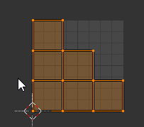
this way i know no overlapping faces
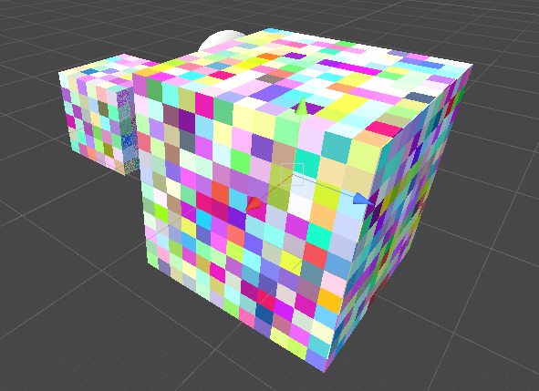
yeah i don't see the problem on that cube, except briefly when i first hit play
but then it clears up
That's beautiful
it's funny because i got to the conclusion to use the world to object node from a completely different thread
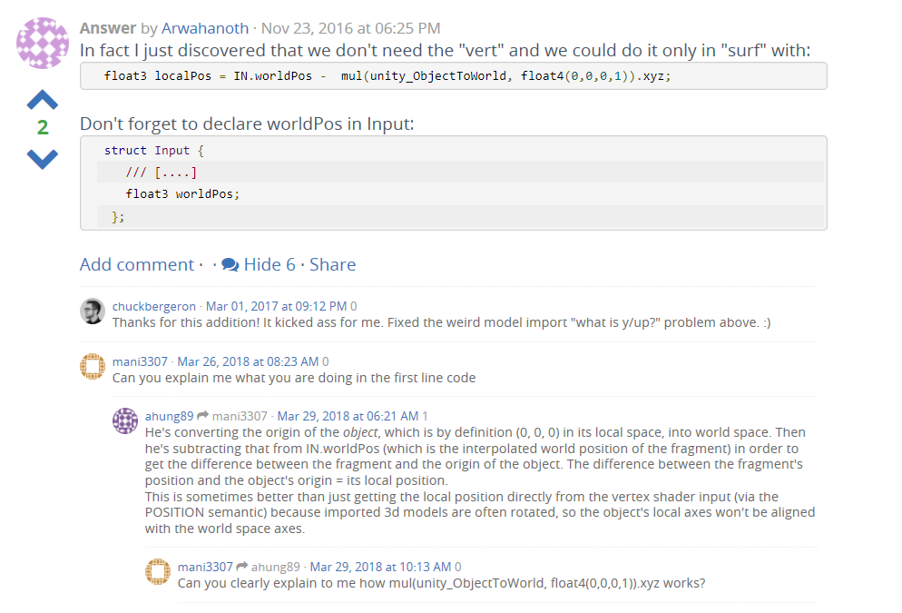
this answer basically said the same thing, and then i realized that's the same thing world to object node does when there's no input
Lol. Well at least we learned something tonight.
yeah I would never have guessed you could use that node that way
Mine's still coming out dark. Do you mind sending your graph so I can compare? I'm probably doing something stupid (It's 1AM >.>)
I can see the usefulness though. Make any shader useable on any model on any of the local axis'. Which, I suppose is what this graph is trying to do (it's from a teleport/glitch shader)
yeah I know i went to the base URL you linked to saw all the shader tutorials 😃
I've converted a few from Unreal to Unity, it's challenging but usually works out pretty well
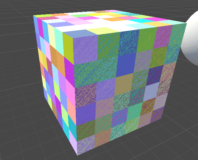
gonna export unity's cube, i''m really curious what the UVs look like that would make it do that
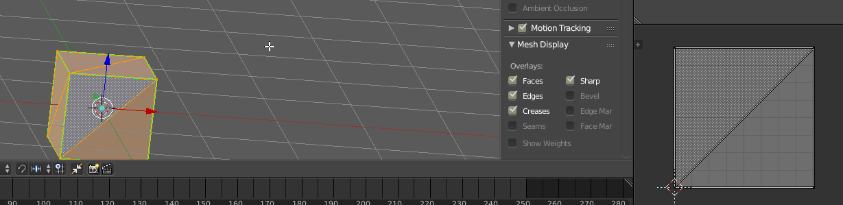
yeah no wonder
all 6 sides are overlaid on top of each other
i'm surprised all 6 didn't glitch
shader doesn't handle that kind of thing well
It probably did glitch, if you viewed it at the perfect angle lol
Anyway, thanks again for helping figuring this out. I'll keep plugging away at this shader tomorrow. Goodnight!
Hey guys, Im just looking for some help converting the first shader in (https://www.patreon.com/posts/groundcrack-25105036). I have done this before, but for the life of me, i cant figure it out now.
It seems to be a depth mask shader
But my version is straight up not working
what does yours look like?
I am using the Triplanar node in Shader Graph but I can't understand how I can alter the XY position of the map on the object. (like we can do with standard materials) i.e. to scale and accurately position a grunge map on top of my main Texture.
Any help would be greatly appreciated. Thank you.
triplanar doesn't use the UVs, it's based on fragment position, so to adjust the position of the map, you have to adjust position being fed into the node I believe
I am trying this solution. But it doesn't seem to be working so I am obviously doing somethingn wrong 😄
Does anyone know if there is something like that available for Unity?
NVIDIA Developer
I believe you'd have to Add not Multiply to offset the texture, multiply would increase tiling
And depends what part of the tech you mean. There is a skin shader in HDRP, and you make a bunch of blend shapes for various facial changes and animate them to get a realistic look, combined with some fine tuned bones to aid in the deformation (especially now that unity allows >4 bone weights)
I will give it a try
Yeah that skin shader while very nice, better than the one we didn't have 😃 is not really the same thing. I have tried a bit. Not very happy in the close ups.
Perhaps there was something I did wrong.
it is important to have all the right maps baked for it, especially transmission/thickness map
@dry island Depends on the chosen pipeline, HDRP has a skin shader I hear, I haven't looked into it. But for Standard Pipeline there are several SSS based skin shaders on the asset store, as well as a couple nice eye shaders.
personally I use this eye shader: https://www.assetstore.unity3d.com/en/?stay#!/content/30762 and the skin shader out of this package https://www.assetstore.unity3d.com/en/?stay#!/content/16000 (however I bought the paid version which has a better deferred version of the skin shader)
that wouldn't be in baked lighting. lights only have one color.
you could try having two lights with different colors
or have the light mix with the object's color.
also this should really be in Lighting, not Shaders
Hi.
Trying to convert some materials to use in the LWRP. Can anyone tell me what the 'equivalent' would be to the non-scriptable pipeline Standard shader in the LWRP?
And also, what is the difference between the Lit, SimpleLit and Unlit shaders in the LWRP?
Standard already has lit and unlit
lit is standard, it gets lighting and shadows
unlit is same and legacy pipeline unlit, it gets no lighting or shadows
(what i call fullbright or self lit, similar to emissive in nature)
simpleLit is just a lightweight version with less features
Thanks...so will use the LWRP Lit shader as a template
yes, best bet
So, where's the part here that you're attempting to write custom value to depth?
... that would be the part i dont know how to do haha. I have tried a stencil, but i cant get the to work with a non-empty pass for some reason
or, I could get it to work, but not within the lines of my 'chasm', rather just over an entire masking object
assuming things haven't changed too much in the renderpipelines in regards to depth buffer, you can put in your frag() parameters, out float depth : SV_Depth and then write to depth in your frag
right! I will have a go at that now, thanks 😃
(how was that not ANYWHERE?!? I went through so many depth examples!)
Hi everyone. I'm not too familiar with shaders, but I want to add a CRT monitor shader to this in game screen. Is there a way to add a shader to a panel?
Yes, I'm not personally knowledgeable at writing shader code, but I know that Amplify Shader (what I use) has the functionality to write shaders for UI components.
Example: https://youtu.be/7kQWWKTTTYc?t=18

With Shader Templates you can finally break free from standard surface shaders. Use the included templates or create your own! Learn more here: https://forum...
@boreal apex sorry, forgot to tag you ^
Thanks. but is there a way to use shaders on panels with default unity. Don't have it in the budget as all.
material layering in shader graph when
You can already. But you need a bunch of nodes.
@boreal apex you can check the source code for the default ui shader and combine a CRT effect with that...

GitHub
A collection of scripts that I use with Unity. Contribute to demonixis/Unity-toolbox development by creating an account on GitHub.
@boreal apex If you give me some time I could potentially knock something up for you
Sure thing, Thanks @desert mural
Hey guys lemme ask something, how would I create a seamless underwater effect ?
I thought about using post processing but I don't know if it would be the most correct way...
I'm almost sure I would have to raymarch, but anyway, any ideas ?
i know of a couple water solutions that just use PP
seems to work pretty well
but of course there's other ways to do it
Post Processing
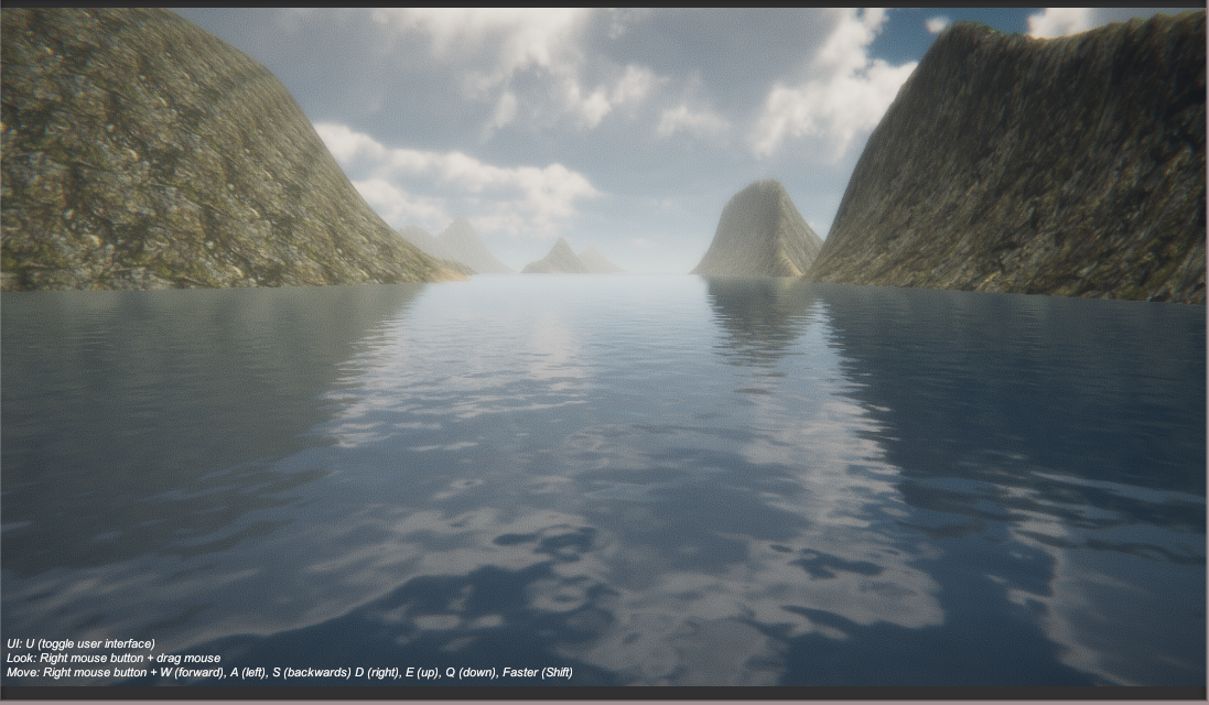
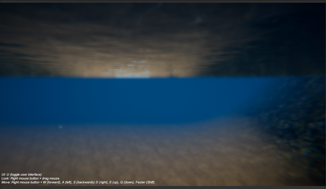
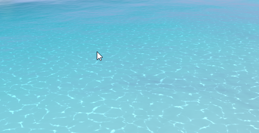
this underwater is pure PostProcessing stack
(plus undersurface shader on the water plane)
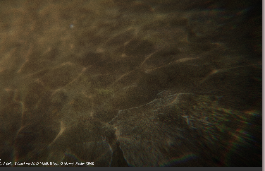
the caustics seem to be a special terrain shader
pretty cool
or possibly a projection, i'm not sure
it's decent if you're targeting lower to mid range graphical fidelity
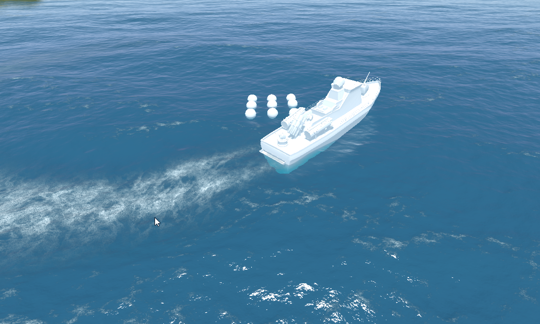
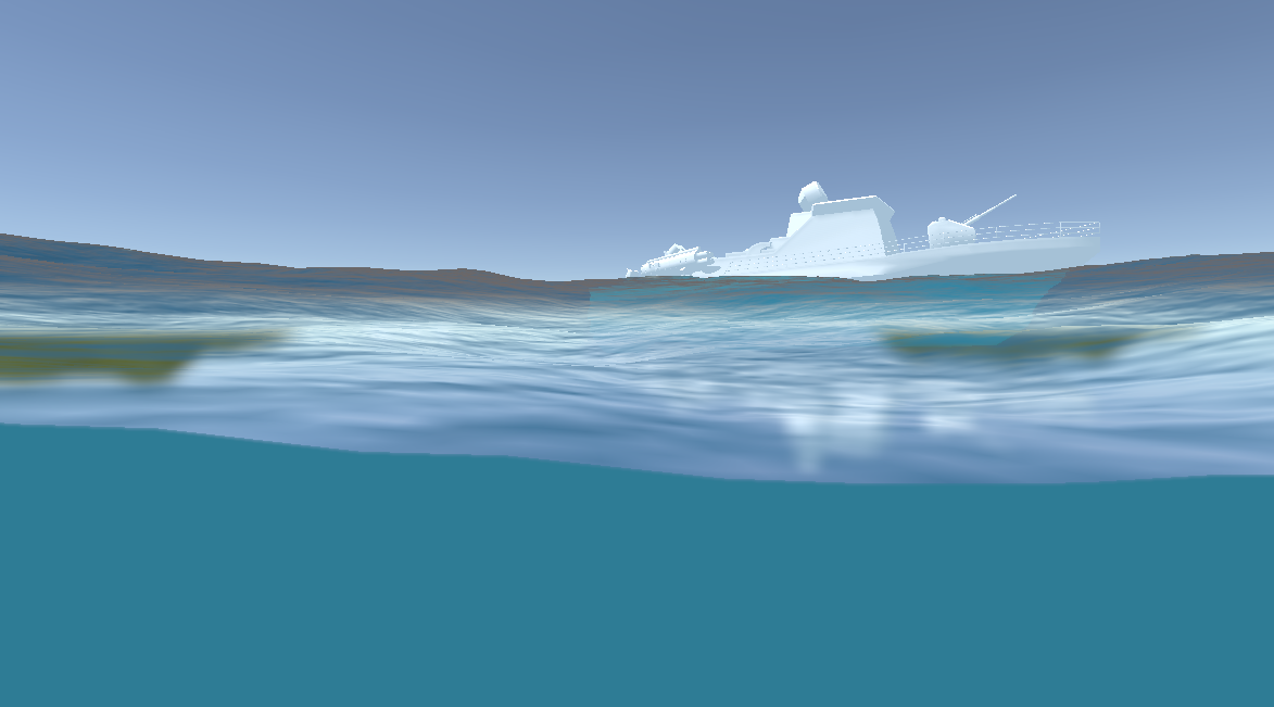
for higher end, I just say use Crest as it's pretty nice looking and free (but best for oceans,not lakes)

GitHub
An advanced ocean system implemented in Unity3D. Contribute to huwb/crest-oceanrender development by creating an account on GitHub.
it uses a custom system for handling underwater that looks fantastic, even supports split rendering (half of screen underwater, half above)
it doesn't yet support HDRP/LWRP yet. but little does
(it's coming hehe)
np
wow MIT license
wonder when we start seeing HDRP water systems :p
I did some basic gerstner waves on pure SG graph before 😄
but that's kinda silly
hehe
well the Crest guy just finished a major refactor, so I hope that means LWRP is next
or HDRP would be better
not sure which he will do first
opne a CPU utilization view :p
would be fancy to get some more descriptive indicator for the compilation
then you'll know 😛
there's that small progressbar on the bottom
but I'd like to get some percentage for the whole queue
yeah would be spiffy
@still orbit not exactly changed on the master branch version but I think text fields not fitting in the node itself could be handled more gracefully
also the input / output name space is super tiny when the property type selector is huge with just wasted space on it
Oh <___< yea., in my haste for GDC I forgot. lame.
even the longest field you can put on property only fills like third of that dropdown bar
its because there was initially up to 3 fields there
ill fix these, thanks for the reminder
np
but if thats the worst you find then im happy 😛
ah, master?
yes
noticed these some time ago but I try to not nag too much about WIP stuff, figured you must know most of these already
yeah, it's on the docket in our bug tracker
nothing seems more broken than it was tho, but then again I was previously testing almost the same version (I've updated the changes from custom function node branch)
there's one thing that kinda bugs me in the UX
it's that I'd want to create new nodes with single click and the only option for that I've found out so far has been to hit spacebar, on mouse alone it's two clicks for a task that you do a lot
and I do make a lot of nodes without dragging the wires (there you get kinda intuitive setup)
also would love some one letter shortcuts on the node list
like + for add, - for sub etc
for most common things
if there's a way to do that already, please tell 😃
no, those don't exist already
they're kind of on the radar for us but not in any short term sense
right now the biggest productivity killer is the compilations after each operation
I hope that sg async thing helps there
🤞
i care much more that you upped it kink, much better than nothing :)
ui problems don't matter much to me
@frigid zinc I was surfing github unity projects and I found this water project: https://github.com/Scrawk/Ceto
really cool
Okay, so after looking in to it. It seems that no one has figured how to get the Light Attenuation data for HDRP yet. Not even the Amplify guys :/
strange, I thought Ceto got canned.
it used to be a paid water on the asset store back in the day.
I guess he finally decided to open source it. interesting.
it was considered the best water available back in it's day
Wow I was testing Crest, and my dude how is this even free ? This is one of the most beautiful water shaders I have seen
yeah Crest is amazing
It even has waves sims omg
I've been watching it for about a year now and it keeps getting better
the underwater stuff is fairly new, before it didn't even have that
Amazing
If I were to nitpick, it fails to not render specular highlights in shadowed areas, but then I'm just b*tching
I haven't noticed but you could always file an issue on the project
Ceto doesn't look bad, I think I like it's foam better than Crest

but it's underwater seems a bit flat
I tested both too, and yeah, the underwater really is rather flat
Crest is waaay better overall
That was the first thing I tested 😂 dunno why I care so much about it
I'm not even making a water game
well it's one of the first things I noticed on aquas
you could kind of halfway move underwater and the fog doesn't kick in
it's very immersion breaking
really bad
keep the player out of the water if you can 😛
otherwise you gotta pay to render all that xD
yeah yeah, dad ;p
keep the player in a dark box to avoid rendering if you can
eheheh
making open world experiences where you can swim and fly is really hard :/
People are not as afraid as us who have experience
I feel like I wouldn't scope for such things until I had a rendering engineer onboard 😛
hahaha are we related
you jump off the cliff if you want 😛
i just set 6 year goals, then as i get closer keep expanding the deadline out ;p
lol 6 years?
im pretty sure ill have gone mad and just be living in a cave as a hermit shouting trig by then
At least you can plan for what seems sensible now and then get 6 years worth of performance at the end of it 😛
it sounds better than "there is no deadline" lol
lol
how do the renderpipes and shadergraph go for naming and refactoring? I feel like that's what truly drives me insane in (tool) dev
wonder if that's a bug
they "move" through distortion I guess
oh they do move, but in time with the water so it looked like the distortion was the water only hmm
is that true to RL?
IRL the peaks and troughs create the refractions
i think water refraction would cause some offset
a LOT of offset
what I mean is that the caustics are the refractions of those peaks
yea its based on the wave shape, but its hard to see the relationship in reality
I wonder how different an ocean's caustics look from the classic pool example
yeah i get what they are
I can't google it without getting CG
very
I found this project that really manages to get the appropriate look https://github.com/AsehesL/UnityWaveEquation

GitHub
unity实现二维波方程交互水面与实时焦散. Contribute to AsehesL/UnityWaveEquation development by creating an account on GitHub.
sadly googling caustics only brings up computer renders for the most part
hehe yeah that is doing a physically accurate simulation. i can only imagine how expensive that is
though i have some nice 'ripple' shaders that work reasonably well
but they don't generate caustics usually
neat find
hide it from Kink3d, he will have a stroke 😛
haha
It has no licence though
About the caustics, he is probably using the already calculated waves to calculate it so I dont think it would be much more expensive
depends how he's doing it
old project, 5.6.3
15ms CPU just for this water
he's doing most of the calcs in C#
would be a lot better as a compute shader
I think the scattering is really expensive
yeah and he's using a second camera with a RT
to render the caustics
nice show off thing, but not game ready
LWRP water uses a second target for the caustics
but it calculates them in screen space in a post effect
its a nice solution
yeah that sounds better
in my old water i did them in world space, I would do screen space in the future...
mostly i just don't like he uses C# to do the calcs
yea should be compute
but hes doing a proper sim right? not really game ready either way
something I noted is that his water surface shader handles specular highlights more correctly
shadowed areas dont get them
I dont know why I nitpick about this little details no normal person sees
yeah it looks pretty accurate
and it's actually very reactive, no delay or hesitation, it really acts like you're messing with water
it's nice overall
it just doesn't leave a lot of room to do anything else 😛
ever seen that WebGL pool water demo ? it looks pretty similiar, bet he was inspired by it
Does Unity support sampler2D (texture) arrays, ie for instances of materials with different textures?
I've seen a lot of demos over the years, it's a popular subject hah

limited hardware support it seems
Actually, I'm not sure if I need texture array. What I want is to use a shader with this code:
later in surface call: tex2D(UNITY_ACCESS_INSTANCED_PROP(Props, _MaskTex), IN.uv_MainTex)
just instance the texture mask
What I've done is exactly the same as the example except I am using texture (sampler2D) instead of color
yeah i was just wondering to myself i you can instance a texture
i'm not 100% sure you can
but maybe @still orbit can give a definitive answer.
🙏
Unity is the ultimate game development platform. Use Unity to build high-quality 3D and 2D games, deploy them across mobile, desktop, VR/AR, consoles or the Web, and connect with loyal and enthusiastic players and customers.
yeah this pretty much confirms you can't
throws the error: Shader error in 'Custom/TileTextureBlend': sampler array index must be a literal expression at line 76 (on d3d11)
they suggest using texture2D arrays heh
seems instancing can only be numerical data
colors/values, etc
i thought it was something like that
goshdarnit
So, i have a goal, some idea of how I want to get to it, but if I can, I would like to get peoples theories on how it would be possible:
I want to make a procedural cracking shader. Not in one spot, like a decal, but instead just a series of random cracks that go all over the object.
For context, i am working in HDRP (normally LWRP, but this is a pet project), and I have a crystal I am working on, trying to make multiple crystals with variable detail (multiple materials, one shader probably).
Ideas?
"the z component of the coordinate is an array element index" wouldn't a uv z coordinate be clamped between 0 and 1?
well it's not really a UV is it, it's an index into one of the Texture2Ds in the array
if you wanted a UV z that would be a Texture3D
What does "serialize as assets" mean? they are assets that appear in the asset browser?
Yes
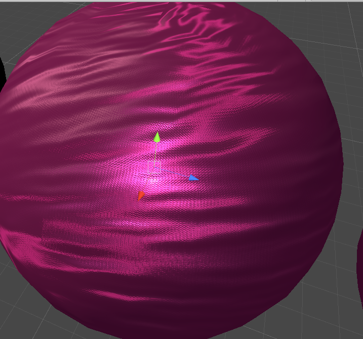
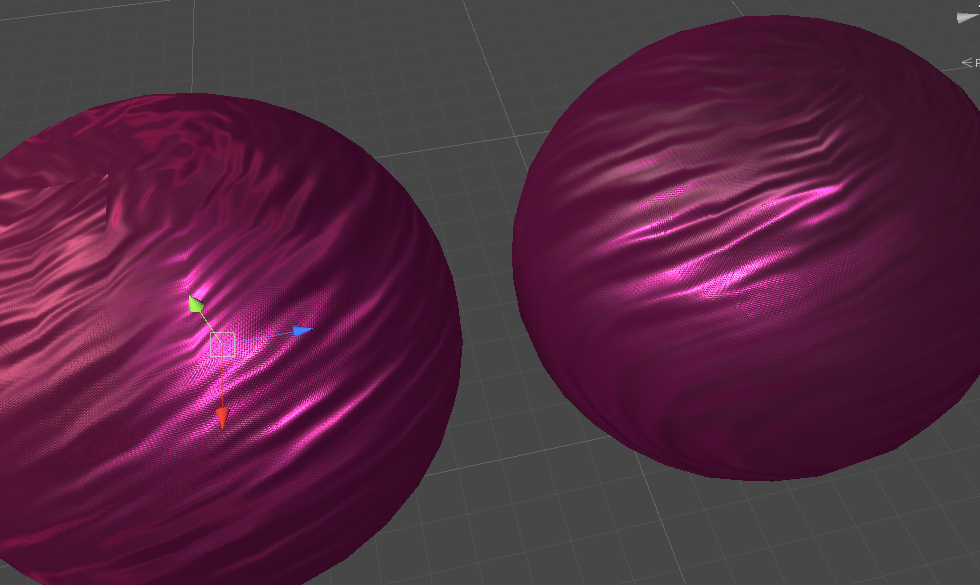
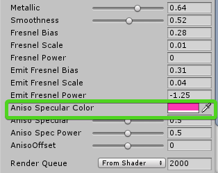
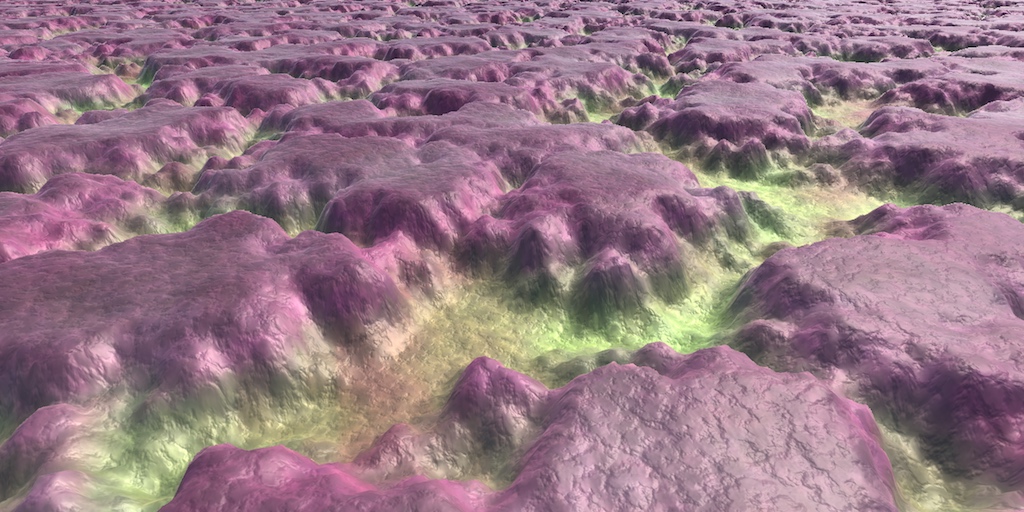
ok finally got my aniso and satiny stuff together, but combining them is either too bright or too dark
this should be burgundy, not pink
That's an amazing material
i guess it's not far from the pre-aniso
not sure the aniso really does much for it
but some
especially if you brighten up the spec color
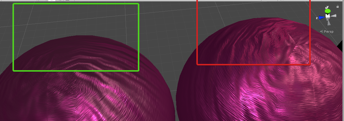
you get highlights in the red area, whereas none without it in the green area
in motion it looks good though
i'm satisfied
just need to clean it up and add some handy features like metallic map instead of sliders
and some AO
Looks like the highlights are purely lightened, maybe they need to be more pink/reddish
pardon my super imprecise language
yeah it's adjustable, i cranked it up to see better
thats a lot of parameters 😛
Is it just me, or are there no procedural crack shaders for unity ... at all? I have been looking for hours, and ive come up with a dozen blender graphs and a guy using parralax to make his -already existing- cracks better. BAH!
does anyone know where i can find the displacement mode in HRP shadergraph?
That doesn't exist in the graph
It's either the position master input for vertex displacement
Or in a near future version, we'll provide a parallax occlusion mapping node, with a depth offset master input, to make pixel displacement
And technicaly, you can have both at the same time.
Trying to learn shadergraph by making a RGB mask shader. I guess I must be doing something wrong already. Any tips to making the Red channel mask the multiply, so where it isn't effecting is not black.
first : if the red channel is the mask, just use the red output of the texture sample, no need for a channel mask here.
And you're trying to channel mask the alpha channel of your texture ... that seems wrong.
Second, if you want to mask a multiply by tint, you have different solutions :
- Take your base texture / Multiply by the tint / lerp the base and the result of the multiplay with the mask.
- Since multiplying by 1 is "do nothing" you can do this : invert the tint (one minus), multiply with the mask, invert the result, multiply with the base color.
Hope it's clear enough
thanks for my advice @amber saffron There goes my plan for procedural cracks using displacement 😃 Maybe normal from texture...
Trying to improve the realism of placed objects in an AR application.
In addition to drop shadows I'd like my placed objects to also be reflected off the 'ground' or plane surface they are placed on.
My shader chops are limited so would appreciate any help or feedback in creating a LWRP shader that is both fully transparent AND reflective. My idea is to create a material with this shader that would then be applied to an actual ground plane attached to each placed object.
2 other requirements is that both reflection intensity and reflection roughness would have to be exposed so that they could be changed in the editor.
Hello!
I would like to update my project to HDRP, any good way to upgrade old shaders(some of them from asset store without hdrp support)?
@tough oxide when our team went from LWRP, we actually found that with a bit of time spent in ShaderGraph, we could replace 99% of our shaders. Complex work gets a whole lot easier. For the ones that cant be done easily, I think you're going to need a shader guy, or to perhaps contact the people on the asset team
@ornate blade alright, but as i know somethings like GrabPass and some other are not existing anymore in HDRP so how to replace them? i searched for documentation about it but i can't find
It depends what you want to use it for. If you are looking at refraction, frosting or distortion, this (https://forum.unity.com/threads/hdrp-shader-grabpass.568585/) seems to be a good thread
@ornate blade okay, i will check this, thank you!
all g 😃
@still orbit Yeah I put just about everything out as a parameter while working so I don't have to recompile every time I want to try something different. In the final I'll probably remove the ones that don't need to be there 😛
How can I make this kind of waypoint marker using ASE?
@woven swift From the other chat
You have to set your render type to transparent
Basic implementation which you can start tweaking.
use object space position as UVs
saves dealing with UVs or any cap geometry
GTAVs markers are also Unlit remember (not poking your minimal example, but reminding)
Lol, good point. Ignore everything I've posted. 😫
Now I realized just how stupid I am 😛
hold on ill do something fun and make it from a cylinder using only a shader 😛
wdym?
well its a cone right
but i cant be bothered to make a cone
so ill do it in a shader
Sounds...... intuitive i guess?
So now that the gradient works, how do I remove the gradient from top and bottom side of the mesh?
thats what im about to show you 😛

that model is a cylinder
if you want it to actually be a cylinder just ignore the top 3 nodes
i'm gonna make sure this gets secretly added to his gdc slides
ASE setup?
idk, probably the same?
Some nodes are different tho, ima try and see if I can port it
only thing im not sure on is colorspace conversion
its probably just an RGB to Linear node
Yea ASE and SG are totally different
most of the nodes work same way, naming conventions differ
all those edges... 😱
I've seen mecanim graphs that boggle reason
@broken field - My project is an action game with beat em' elements.
I look back at the old (4.6/7) version of my project in abject terror of the forsaken mecanim graphs of pretty much all of the (partially)-implemented characters.
I wish ECS or playables was a thing back then.
since that time, I've used mecanim as a pure state machine for various things than an animation tool 😦
I knew you were a savage as soon as I laid eyes on you
unity's finally bringing us DOTS-visual scripting and I'm intrigued
Hey guys, has anyone found a way to smooth jagged normals generated from NormalFromHeightMap in SG?
don't feed in so rough height?
make sure your height map isn't being point sampled?
Any way to improve the waypoint marker?
Maybe I should use a hollowed out cylinder mesh
The height is actually very smooth, its parsed noise thats been stepped, so its nice and curvy. What do you mean about the point sampling @still carbon , i havent come across that before?
@woven swift I had the exact same thing, and i found that doing the gradient by object height got rd of that annoying top bit. You can also use a gradient node, and compress it however you want if you dont want a linear raise. E.g, I ended up with a fairly sudden falloff around 1/4 the way up, which gave it more of a ground effect kind of thing
on your height map import settings, check the filtering
but if it looks smooth applied normally as color then that's not the issue
idk how to do it on ase
but I think the world space normal would do it 🤷
ok im lost
Colour seems smoothly applied
you can see a fairly serious degradation of quality post conversion
Yeah I think the world space sh_t doesnt work. Any idea how to get rid of the top part?
@woven swift does ASE have an "object position" node?
like world pos but in object space?
theres vertex potision
might work? if you get the y value of the vertex position, it will create a gradient (which in object space, means the bottom of you object is 0, and the top is 1). You can invert that, and feed it to colour and alpha for the effect
If its world space it will be rather annoying to use
your heightmap is pretty extreme and narrow for the pattern shape
can you dial down the intensity?
The vert position have XYZ, X, Y and Z output
before feeding to normal from height?
ok i nailed it using the Y output
and it somehow make the thing glows, i'll count that as a feature i guess
@woven swift nice 😃 I think you are feeding it into emission
@fervent tinsel just to clarify, when you say intensity, are you referring to the amount of noise/pattern shape, or to the amount of white?
@ornate blade what no im feeding it into opacity
I only feed color into the emission
your colour is in emission, thats the glowy node. If you wanted to get rid of the glow, you would feed it to albedo.
Im ok with a slight glow :P
yeh, looks pretty good 😃
@ornate blade amount of white, just try to put multiply there and use property to dial it down, see if it smooths down on some value
ahh, gotcha, 2 secs
nope, just a less intense but still jagged map
@woven swift If you multiply that by the colour -then- feed it into emission, you will see that emission gets less as it fades away, almost like a double fade. Can help with the falloff
cant remember how, but you can also do something to that to make the gradients height chang
looks cool though XD Where are you controlling your emission intensity?
haha im not sure how in ASE, but make the colour HDR, and you wont have to have a separate slider
Think I get the idea
Y pos of Vert Pos > One Minus > Multiply by marker color and a float value feed into emission
@ornate blade you probably just don't have enough resolution for such dramatic height differences on such few pixels width
also
you do check it on actual model?
and not on that preview ?
yup. Its so close to being exactly what I want haha. Maybe I will try with less noise, see how that goes
(that picture looks fine until you look closer haha)
@ornate blade your intensity setup still makes the marker looks too solid. I think it would be distracting so I just went back to the primitive version
@woven swift you can multiply your result by a final float into the opacity so that you get a less distracting view 😃
Guess that'll be for later
good luck 😃 look forward to seeing the result!
double sided will be in shader settings, mesh shadow ... mesh renderer i think
Disabling the culling feature really did some weird shit to the look os the marker lol. its a must see
Hey folks! I'm back with more orthographic depth issues!
Would anyone be able to test the following for me on windows: Using the latest Post Processing stack (v2.1.4), SSAO does not work when using an orthographic camera?
I can provide a sample project if that helps
Orthographic cameras will have issues with many things - I wonder if there's a list of what doesn't work with them
Could be a bug in that case 🤷 we'll see when someone in the know gets on 😛
yeah, it's super weird
I saw the issue in my game in the wild, but don't have a good windows machine to test one (just a really slow old dual boot mac)
doesn't SSAO depent on depth buffer? curious how that works for ortho - not sure how it deals with depth
it should work fine
I had an issue getting depth working for a custom shader the other week, so it definitely can work. and as mentioned, it works fine on Mac

see! 😄
@random meadow 1. your game looks awesome. 2. excuse my ignorance, but which part of this screen shot is affected by shaders?
Sample Texture2D node freezing editor in hdrp 5.8 when added to subgraph
@manic mantle thanks! It’s easiest to see the ssao on the building wall where the boxes are
That’s without ssao
where its adding the shading around the boxes?
Yeah
is hte shader applied to the box prefab?
It’s a post processing effect
It takes the depth of the scene, and where stuff is close to each other adds “shadow”
do you define depth just via the z axis?
i dont know much about shaders so sorry again for silly questions hehe

GitHub
Post Processing Stack. Contribute to Unity-Technologies/PostProcessing development by creating an account on GitHub.
Yeah, z-axis, my game is 3D, but an orthograohic camera and forced perspective make it look flat
is SSAO built into unity?
or part of that postprocessing package at least
does your player also have a shader on it to add that light glow ?
Yeah, it’s part of the post processing package
nice
That also includes the bloom effect
is it applied to the entire scene?
Yes
interesting
It’s a post effect, so the full game gets rendered, then that effect is applied to that image
ive been working on a 2d game for awhile and wanted to use shaders, but you always see these elaborate shaders that i feel dot really fit with a pixel art game.
Well, it’s taken a long time to perfect
so im guessing you didnt just go into unity , say 'add this shader' and then it was magically perfect? hehe
man sometimes i hate unitys docs
hehe
Maybe only sometimes, just be thankful it's not like Unreal docs 
@random meadow is there anything you could give me a heads up on in terms of issues you ran into while trying to perfect it?
Ummm
I wrote a lot of custom shaders, so it’s good to start understand how those work
Other than that, stick to the pixel grid if you want your game to look good (imho). I hate when a games ui is a different resolution from the sprites
Also, the docs team work really hard, so if you have a problem then it’s really helpful for them to leave some feedback 👍
sure. my biggest gripe i just saw was that some effects have images and others dont. or if they had before /after images like you showed, that would be helpful too
like this https://github.com/Unity-Technologies/PostProcessing/wiki/Color-Grading
it just shows 3 images and says something about instagram.
GitHub
Post Processing Stack. Contribute to Unity-Technologies/PostProcessing development by creating an account on GitHub.
i mean, i could draw a conclusion of whats happening, but id like it if i could see what it looked like before processing took place
I believe the first is the original and then the other 2 show different grading applied
Just download the package and test out all the different post processing modules it provides to see what they do 😛
well of course... but thats why docs also exist 😛
As a docs writer, can confirm: yes, please leave us feedback. It’s golden for us to know what you magical users think is missing from the docs.
I find docs feedback one of the least satisfying channels of communication
but I wish I could do it more often
The rating system at the bottom of Manual pages?
Yeah
How come?
I don't even remember if it sends you an email
At least with bug reports you have something that is tracked
I think the way I tend to get them noticed is actually having a bug report where I append that the docs could use improving
I just use the disqus notes https://mvi.sh/notes/ @sabresarus made to augment docs instantly for the few who use it
But I've never seen a note from it become a part of the page even though apparently quite a few people internal know about it
Hmm, yeah, I get that it’s really one-way, which would be unsatisfactory for the person reporting.
thinking of any mechanism of reporting a good "hey we implemented your change" even months down the track is a satisfying conclusion
"hey we banned this person" yaaaaaay
The system truly does help the docs team, though - we use the page ratings+view counts+feedback+change requests to make tickets for updating individual pages, based on priority, and then assign them to relevant writers.
So for Shaders, it’d get pinged to me or my colleague in Seattle.
I'll try to use it more often then because I think I've only touched it once or twice
But this is a very good point.
We’ve got DocsWeek coming in April - I’ll bring this up for a discussion; see if we can implement a feedback mechanism like for bugs with our new tools, when they get implemented :)
And yes, please do!
The more constructive criticisms you can give, the more we can implement - both on specific pages and in future writing :)
Even something as simple as actually making the feedback buttons have an animation - as corny as that sounds might actually make clicking them more appealing
you click "This page needs code samples" and it's as if the page just eats it locally
I may go back through my notes if I have time and create reports for them though 😃
<3
I might just be a glutton for punishment and extra work, but goddamn you being willing to do that gives me a happy.
Unity docs are one of the things that truly makes being a Unity dev that much easier, so it's really the other way around :P
When you've used other tools with awful docs you really come to appreciate how good Unity's are
Also, FYI, we’re also working on how to include feedback on the packages docs. It’s a real hassle that when I send lwrp docs our into the ether, I can only just really cross my fingers and hope they’re good. We have New Tools™ coming, so I hope we can get a good solution for this!
And aww shucks - I’ll screenshot that and share with the team :)
👍👍👍👍
@tawdry hearth where are you based?
Also, anyone any ideas about my post processing ssao + orthographic issue yet?
here's the PP issue btw https://github.com/Unity-Technologies/PostProcessing/issues/774

GitHub
What happened? Scalable AO does not work on Windows when using an orthographic camera. The effect just isn't present, with no indication in the logs as to why. The effect works fine on OSX, so ...
@random meadow
Me: I’m in the Copenhagen office, sat with the Graphics team doing lwrp (and other cool stuff).
There’s another Graphics writer sat with the Shader Graph team in Seattle.
There are some writers in Montreal and SF. One in Singapore. And the bulk of the docs team is in Brighton, UK.
@tawdry hearth ah cool! I'm from Brighton (just moved to Taipei), so I know a couple of those guys. Siobhan and Paul 😃
Woo! They’re good eggs ^^ I’m going for two weeks in April to sync up and discuss tool and processes. And to have lunch with them at Milk No Sugar :p
ah nice!
so shader wizards.. is there a way to use post processing to make only specific gameobjects go black and white on the screen but the rest remain as normal ?
does it need to be post processing effect to begin with?
you could do that on regular shaders
well id have to go around modifying surface shaders then
was hoping i could just do it overlayed with post process
depending on the use case, one could mask the objects in stencil buffer and use it for PP
but you'd then need to write the objects that you want to control + also geometry that can occlude it on top of it
so i can push all child GOs to the stencil then change the colour of those specific pixels
hm okay ill try it out - thanks
not sure if this should goes to shaders but, is anybody have a guide about using gpu instancing and culling (distance and fustrum)?
not sure culling is related to shaders but gpu instancing is in the documentation for unity
the engine already does frustrum, and you can optionally add occlusion culling too
if you want to cull by distance you'd be better off doing this engine side not shader side
oh i should explain it clearer, when doing gpu instancing via drawmesh indirect instancing
well the docs have examples of using the method, otherwise there's a bunch of tuts you can find on youtube when you search unity gpu instancing
in the documentation stated that it doesn't use culling
"Use this function in situations where you want to draw the same mesh for a particular amount of times using an instanced shader. Meshes are not further culled by the view frustum or baked occluders, nor sorted for transparency or z efficiency"
Yeah, so you'd have to manually do some frustum culling of the positions you're feeding in to be instanced at. A good case for learning a bit of ECS/Job code to do that very efficiently, or in the least splitting up your draw instanced calls into radial chunks so you can easily cull chunks without any real overhead.
can do GPU based culling in computer shader supported platforms
Hey, I was hoping someone could help me. I know nothing about shaders but was looking for something that would let me see one object through another in 2D, using sorting layers.
kind of what I mean
@lone stream u can use culling groups and bounding spheres which get culled internally in unitys culling step
The groups have distance bands which can be queried to build your drawmesh instanced/indirect calls
How can I alpha test beforing writting to StencilBuffer? I have the following shader and I want it to reveal whats behind it, but considering the alpha from the texture I'm using.
Shader "Skydome/ConstructionSystem/GridRangeRevealer"
{
    Properties
    {
        _MainTex("MainTex)", 2D) = "black" {}
    }

    SubShader
    {
        Tags{ "Queue" = "Geometry-1" }

        ZWrite off
        ColorMask 0
        Lighting Off
        Cull Off

        AlphaTest Greater 0.5

        Stencil
        {
            Ref 1
            Comp Always
            Pass Replace
        }

        CGPROGRAM
        #pragma surface surf Lambert

        sampler2D _MainTex;

        struct Input
        {
            float2 uv_MainTex;
        };

        void surf(Input IN, inout SurfaceOutput o)
        {
            float4 c = tex2D(_MainTex, IN.uv_MainTex);
            o.Albedo = c.rgb;
            o.Albedo = c.a;
        }
        ENDCG
    }
}
@uncut karma ooohh. . . that interesting, i never thought Culling group can be used with Drawmesh
was trying to learn about Hi-Z culling
Can anyone help me? I need to create a mask(plane/quad) that reveals an object behind it(another plane/quad).
The background one has a grid texture and the mask should only reveal that according to the texture mask on the mask object
this is what I got so far writting on the Stencil Buffer
hey guys, can I do a two pass blur in a single shader using "Pass{}" or do I need two materials and call Graphics.Blit twice
the problem is that it uses the mesh shape, and I need it to apply the texture alpha into the background color
looking at one of the many gaussian blurs out there, it looks like multi-pass is fine

GitHub
Screen and UI gaussian blur for Unity. Contribute to PavelDoGreat/Super-Blur development by creating an account on GitHub.
in fact this guy does a 5-tap, 9-tap, and 13-tap all in one shader
thanks @frigid zinc
does viewDir point from the camera to the pixel or from the pixel to the camera?
cam to pix i think

Stack Overflow
Can someone please point me to the explanation behind computing world space view direction using following equation:
float3 worldSpaceViewDir = _WorldSpaceCameraPos.xyz - worldPos;
Why do we subt...
this suggests it's the other way
😦

Learn to implement Subsurface Scattering in Unity. This technique is fast and allows to render even more realistic materials such as skin, wax and marble.
this guy's shader works even though he got the vector diagram wrong because of this
well he's trying to describe half-vector
he did that for illustrative purposes

i think Shaderforge was smarter about it and just didn't put arrows on the light and view vectors as to not make it confusing
if you draw the arrows going in as they really are, it looks strange to have the half going out
like it's a reflection
but it's not
but then again, they may be going out
it would make sense for it to be a vector from the pixel to the camera
let me see if i can find a definitive defintion
for using it which way it goes really doesn't matter
it's all about angles

yeah Shaderforge says it's from the pixel to the camera
i think that is correct
direction can be flipped at any time anyway by scaling it by -1
no, I take it back, his diagram is correct, I just didn't quite get why he put the minus sign in his actual code when he takes dot(V, -H) but now I get it, he wants a subsurface scattering that is strongest on the edges.
ok, I made a little foliage shader
sweet
Hello guys, do you know how to render a PPSv2 image effect behind the deferred fog?
i wanted to render this image effect behind the fog because it kinda looks weird being rendered on top of the fog.
https://github.com/jean-moreno/EdgeDetect-PostProcessingUnity
I kinda have a theory for the work around about my problem though, like making the edge's color the same as the fog color's depth

GitHub
Unity legacy Edge Detect image effect ported to Post Processing Stack v2 - jean-moreno/EdgeDetect-PostProcessingUnity
unity's compute shader page leaves a lot unanswered ... it uses this:
// test.compute

#pragma kernel FillWithRed

RWTexture2D<float4> res;

[numthreads(1,1,1)]
void FillWithRed (uint3 dtid : SV_DispatchThreadID)
{
    res[dtid.xy] = float4(1,0,0,1);
}
but if you had more than one function how does it know which to call ?
i can't imagine FillWithRed is a built in function it seeks out, doesn't explain what dtid : SV_DispatchThreadID is either =/
any one dabbled with these things
There used to be a great resource but it was taken offline
I build shaders, renderers, games, and other stuff that's fun to stare at.
This should answer some of your questions
aw noice. been meaning to learn compute shaders
Hi there people!
Quick question.
If I have a shader with 2 passes, and in Pass #1 I create some extra vertices in the geometry shader
will Pass #2's vertex shader have knowledge of these created vertices?
My understanding says yes, but the results say no, some clarification would be wonders.
No pass 2 won't have the new verts
you'll probably notice that if you do something in a geometry shader which is quite different from the default mesh the shadows won't match. You'd have to write a shadow caster pass with the same geometry shader to get them to match. Same problem there
@last robin is there a way to have these new verts in pass #2? Kinda need em :/ I need to translate the vertices of the original mesh according to the ones I created in pass #1
So I don't see any other way? :/
Not that I know of
i think your options would be doing it on the cpu or maybe there's some sort of solution with compute shaders, not too sure
I just need the new verts in pass #2 ya know
ye im doing it on the cpu right now, but wanted to move it to a shade to increase performance :/
shader*
also why wouldn't newly created geometry persist between passes inside the same shader?? that's so dumb
are you absolutely sure?
i'm positive, yes
what's the use of newly created verts though if we can't even access them in subsequent vertex shaders in different passes? makes no sense
doing a quick google search it looks like you can use a compute shader for what you want https://stackoverflow.com/questions/48243084/unity-compute-shader-to-generate-mesh-data-failing-to-calculate-all-triangle-ind
This guy has a link to a CPU implementation and the same thing but with compute shaders, so maybe this helps. Just make sure to fix what the solution reply said was wrong
Stack Overflow
I have recently been working with generating mesh data for a spherical planet made from 6 subdivided planes in Unity3d (like this). I created an algorithm in C# that lets me make the meshes on the ...
with non-compute shaders pretty much nothing will persist
but withing the same shader but in different passes i feel like vertex data should defintely persist
Unless you use them to render to rt and use it as feedback loop..
i'd guess it's done that way because it's faster to not have stuff persist
i don't know really
but if you want things to persist compute shaders are the way to go
or some complicated render texture loop as olento mentioned
but that's basically what compute shaders do but hacked together with non-compute shaders
i've never worked with compute shaders before so i'll read up unto it ig. thanks for the help.
@fervent tinsel care to elaborate a bit how that works?
@valid flax ah that wasnt really for your use case but to the comment about noncompute shaders data persistency
You could use that kind of stuff for trivial water responces, snow tracks etc
Does anyone know how to sample a Texture in a custom shadergraph node (CustomFunctionNode)? I want my custom function to be something like
static string Func(
    [Slot(0, Binding.None)] Texture2D Texture,
    [Slot(1, Binding.None)] out Vector4 Out) {
...
}
This does correctly display an input node of the texture type in the shader gaph editor, but I cannot find documentation or a example that actually samples this texture.
All of Unity's own nodes use a different API, which is undocumented.
Anyone know how I can get the name and the sampler name for the input texture?
Why is my transparent texture being repeated like this in shadergraph?
Nothing going into that UV(2) slot btw
it's working exactly as expected
clamp will extend the edge pixels
it's likely the colour channels are encoded like that
and so it's repeating the edge pixels of the colour channels
in fact, in your case it's not even repeating the edge pixels
it's just entirely how the colour channels have been encoded
I am assuming shadergraph just doesn't display the alpha channel
If you do for some reason want to control what is encoded in those channels for Photoshop you can use something like SuperPNG, and also it's fairly common to bleed the alpha using something like Flaming Pear's Solidify
I've used transparent png's many times straight from photoshop.
There is no issue here, everything's working as expected, ShaderGraph is just not displaying the alpha channel information
Never had to use any plugins before, and to be honest.. im a bit reluctant to..
SuperPNG is a must have for photoshop to control the alpha channel.
It's basically TGA alpha channels for PNG files
Yeah, it's a great plugin.
(Example showing how the alpha channel is still there, just not displayed: https://i.snag.gy/bdcoq7.jpg )

^You could have just used a preview node here 😃
I could have also not 😛 (I was testing some other stuff first and this was quicker at the time :D)
Come to think of it, I have struggled with a hard coded HSL shader in the past. Maybe that was the reason. Just to progress, I sorted my issue now by using a channel mask, as I'll lbe trying to split RGB into user defined colors on this shader. But I'll check out the plugin once I hit a creative stop.
nested SG subgraphs now in SRP master 😃
Ok. I'm going to need some suggestions on how to do a color replace RGB split .."thing". Meanwhile, I'll go grab that plugin. 😏
I'm just trying out semi-random nodes at this point.
My goal is similar to this shader on the store.
Replace R,G,B values of a map (with alpha) and lay that on top of the albedo map.
this probably has some awful blending something or other but 🤷 https://i.snag.gy/bAYfkl.jpg

it's where I would start personally
Cheers man. That looks pretty spot on in my oppinion.
something always crops up when you start getting complicated - colour blending is a deep topic that needs some expert hands sometimes, so hopefully that does the whole job 😛
Yeah, I might just screenshot your solution and stick to a simple alpha mask for now. And return to complicate things once I start to get the specular where I want it.
Getting there though! dynamic dust, damage and now design 😉
@amber saffron which is why I only use TGA. PNG is for suckers 😛
PNG is lightweight on your repositories 😃
Not a problem I have to worry about 😃
Hello! I'm struggling to properly use the CommandBuffer.DrawRenderer function in a Post Processing Stack custom effect. I'm trying to use it to create a mask using given renderers, but rendering this scene like this..
.. creates this result:
As far as I can see, this is caused by wrong vertex function being used. In this case I used the VertDefault included from the Unity hlsl library, which goes like this:
VaryingsDefault VertDefault(AttributesDefault v)
{
    VaryingsDefault o;
    o.vertex = float4(v.vertex.xy, 0.0, 1.0);
    o.texcoord = TransformTriangleVertexToUV(v.vertex.xy);

#if UNITY_UV_STARTS_AT_TOP
    o.texcoord = o.texcoord * float2(1.0, -1.0) + float2(0.0, 1.0);
#endif

    o.texcoordStereo = TransformStereoScreenSpaceTex(o.texcoord, 1.0);

    return o;
}
it might help to explain what result you're expecting or trying to achieve.
Before I tried a vertex function I found online (this one work with Cg as it requires the UnityCG.cginc include):
    float4 simple_vert(float4 v:POSITION) : POSITION{
        return UnityObjectToClipPos(v);
    }
.. and it worked (created the mask exactly where the mesh is) but the result was shaking due to temporal AA.
ok so you want the mask where the camera sees the object?
@frigid zinc I'm expecting to get the same thing as on the first image, but with a solid color drawn on some meshes and a uniform background.
Like the second image, but with the ball in the correct place and size.
I think you want to use DrawMesh instead of DrawRenderer
I'm completely new to shader programming, but I kind of know what's going on and why it renders like this now (since I'm using a vertex function that is meant to process a Render Texture, not meshes in 3d space).
I would mostly like to know if I can somehow render it properly, but without the shakiness from the TAA.
it has an argument for the object's transform
to place it correctly
something like DrawMesh (m_SphereMesh, Sphere.transform.localToWorldMatrix,Sphere.m_Material);
takes the mesh, it's transform, and it's material as arguments
did that work for you, @edgy star ?
I haven't tested yet - I first wanted to look into that simple_vert function again. I'll let you know when I try DrawMesh. 😃
ah ok 😃
@frigid zinc Tried that - nothing changed. Most likely the problem lies in the vertex program. As far as I understand, the VertDefault function from HLSL libraries puts the geometry inside screen's UV space. If I change the screen resolution to 1:1, the red part becomes a perfect circle.
hmm
            {
                float4 pos : SV_POSITION;
                half2 uv : TEXCOORD0;
                float4 screenUV : TEXCOORD1;
                float3 ray : TEXCOORD2;
                half3 orientation : TEXCOORD3;
            };

            v2f vert (float3 v : POSITION)
            {
                v2f o;
                o.pos = mul (UNITY_MATRIX_MVP, float4(v,1));
                o.uv = v.xz+0.5;
                o.screenUV = ComputeScreenPos (o.pos);
                o.ray = mul (UNITY_MATRIX_MV, float4(v,1)).xyz * float3(-1,-1,1);
                o.orientation = mul ((float3x3)_Object2World, float3(0,1,0));
                return o;
            }
this is taken from a command buffer shader using DrawMesh
it calculates some things you probably don't need like ray and orientation
And the aforementioned simple_vert function from UnityCG.cginc seems to work properly, but it's all shaky (it gets displaced by TAA every frame, but the results are not blended into and antialiased image). So my main concern now is whether it is posible to either:
- Render this mask utilizing TAA (get an antialiased mask)
or.. - Render a sharp, not antialiased mask, but without it being displaced every frame.
Hmm.. I'll look into it. I've got a question though, since I'm a beginner. That vert function is of type v2f. Does it mean I'm expected to pass a v2f argument into the fragment function?
v2f is the same as VaryingsDefault in your example
it's just an arbitrary struct name
I know, but as far as I understand, vertex function gets executed and then its result gets passed into fragment function argument, right?
So the return type of vertex function must match the type of argument in the fragment shader? Is that correct?
So it's a strict rule in shader programming or just a convention? It seems pretty tough to understand what is really going on under the hood.
vertex function lets you do vertex operations
fragment function then lets you color the surfaces of those vertex
so generally, yes you want the output of vert to be the input to frag
i suppose you could ignore all the changes you just made
but then it wouldn't make a lot of sense to change anything hehe
if you're just starting out, i really recommend this shader tutorial series
A collection of tutorials that cover how to write your own shaders in Unity.
Yeah, but those changes could be saved in a different form and still be accessible even if fragment function was initialized with a different struct.
it starts from the very basic up to the very advanced
and i think it even has a section on command buffers
If cg/hlsl were built that way.
(or maybe not, i might be thinking of another tutorial)
Thanks!
Might come in handy.
And you may also be thinking of this:
http://www.alanzucconi.com/2015/06/10/a-gentle-introduction-to-shaders-in-unity3d/

Learn how to wrirte shaders in Unity. Free shader tutorial with examples and source code ready to download.
yeah could be, he's got some nice tutorials. but it's nowhere near as comprehensive as Catlike
(IMHO at least)
Got another question (related to the code provided by @frigid zinc ). That code clearly uses stuff from UnityCG.cginc, but I'm now using HLSL (Unity itself recommends switching to HLSL when writing post processing effects for the PP Stack). There is a lot of stuff in UnityCG.cginc (and others that are included inside it) that doesn't seem to be present in StdLib.hlsl. Am I missing something?
Stuff like ComputeScreenPos (float4 pos), UNITY_MATRIX_MVP, UNITY_MATRIX_MV, etc.
GitHub
Post Processing Stack. Contribute to Unity-Technologies/PostProcessing development by creating an account on GitHub.
It's in the manual too.
(the exact same document)
i think they mean in reference to making effects for SRP
First thing to note: we don't use CG blocks anymore. If future compatibility with Scriptable Render Pipelines is important to you, do not use them as they'll break the shader when switching over because CG blocks add hidden code you don't want to the shader. Instead, use HLSL blocks.
but if you're targeting legacy, you'll need to use the older stuff
note the words 'any more'
sadly everyone around here acts like standard pipeline no longer exists
I doubt "need" is the right word. I guess HLSL is good for both legacy and SRP, while CG works only in legacy.
unity included 😛
That's how I understand it.
But StdLib.hlsl works only with HLSL and UnityCG.cginc works only with CG, right?
like I said, i think it's more about which pipeline you're targeting
you can mix and match but dont
more than likely the old macros won't work in SRP
rather, it's advised that you don't haha
actually how does Unity handle that
for things like PP v2, that work on Legacy and SRP?
PP v2 is in HLSL.
separate shader for each pipeline?
it doesn't matter if it's HLSL or not, i'm talking about the fact each pipeline is incompatible with each other
No, because according to that manual, HLSL seems to be fine for both legacy and SRP.
right as I said, CG and HLSL are 99.999% identical
but the pipelines are not identical in any way
so they must have a separate shader per effect for each pipeline.
Maybe you're right. You can check in the package.
I'm on the GitHub version at work and not sure if fully up to date. The project I work on here is on Unity 2017.4
you shall get no answers out of me
lol
postprocessing doesnt need the stuff that gets generated with CGPROGRAM/ENDCG wrappers
that typically handled generating meta data passes, shadows, etc
yeah I get your point, so it's pipeline agnostic
to an extent
it's like i was showing 0lento yesterday
Amplify added the ability to make PP effects
Anyways, you got me convinced to switch back to Cg. Will make some things easier. Seems quicker to optionally copy-paste some macros from StdLib.hlsl than from Cg libraries.
and all it outputs is color
doesn't care about anything else

their PP effects still use CG though 😛
shame on them 😛
they autogenerate the editor stuff for you too, it's handy
That update in ASE is what made me wanna pick that ambitious Post Processing effect task lying around. But I ended up learning Cg/HLSL because without those basics I couldn't do crap even in ASE when it came down to post effects. It will surely be a useful skill though, since noone here has experience with shaders, and I'm the tech-arty guy anyway.
In that doc they stated that Cg generates some ugly stuff underneath, so for performance reasons it's better to use HLSL (it will get compiled for different platforms too anyway).
makes sense i guess then.
it's probably better if they migrate to something industry standard anyway
In practice there's an obvious difference in macros found in .hlsl libraries vs .cginc libraries.
There are different functions, structs and stuff across those libraries. If you use ones from Cg it's not so straightforward to switch to HLSL ones. I guess they're built with different things in mind.
perhaps
i thought you mean structure in some way
because when i compare hlsl vs cginc, they look identical
(from PPv1 and PPv2)
only define is different
but no doubt they took the opportunity to rewrite and refine their macros.
i notice V2 uses a lot more compute shaders
might be a factor in that also
Hey @frigid zinc ,
So you remember how we were a little stumped on the translation of this setup from the example?
Turns out we might have misinterpreted what the article was saying. At least, I certainly did. You still have to feed in a position into the WorldToObject node, which is typically (in his examples) the world pivot of the object.
This basically fixed everything. Lol.
@frigid zinc The vertex function you provided doesn't do the trick either, but it's just a matter of doing proper maths on the data. It is however rendering it 3d space (as desired), because it gets affected by TAA shaking.
(the gif is slowed down, but it shakes every frame)
Is there a way to actually get an antialiased image using DrawRenderer?
I need Temporal AA - can't drop it in this project. But how to actually make proper use of it inside of a custom shader?
Or how to at least capture a raw image without AA, but without temporal shakiness as well?
Anyone worked with Temporal AA?
I see @tame topaz I'm still not 100% sure on that since it was working for me. but I will give that a shot. I was kind of thinking that's what one might have to do until i found the pages about using worldPosition node with no input.
but maybe it is required after all.
@edgy star i'm not sure how you would execute a command buffer but not have it affected by TAA
hopefully someone else will happen along that knows the answer to that question.
Yeah, I'm a little confused about it too. But if you pump the objects world pivot as a value, it works perfect. Basically, you can define where the shader origin. By default, it uses 000, which is why it would break if the object wasn't at the world origin (which is in all cases, of course).
yeah makes sense, i mean i saw the effect scaled with object movment, but i figured that was what they were after.
but maybe it made less sense the farther into the effect you go. I never did take it any farther.
@edgy star only advice i can give is to maybe try executing your command buffer at different points in the render process.
http://resetoter.cn/UnityDoc/ScriptReference/Rendering.CameraEvent.html if you can do it before PP does, maybe you can avoid it's effects.
there's one called "BeforeImageEffects"
might do the trick
or maybe even earlier
@frigid zinc That's exactly what I thought when I was leaving work. Great minds think alike, I guess. 😄
I even left a note for myself to check if moving it before PP does what I need, just in case I forget until Monday. If it works, I could keep my mask inside a temporary RT and then execute the script that actually uses the mask (this one has to go after the stack, because it can't be affected by color grading - I need a UI-like overlay effect).
sounds like a plan.
is there a way to get a vertex position relative to its skinned mesh position in shadergraph?
i'd assume vertex position would return the current skinned mesh position for a skinned mesh. but someone correct me if i'm wrong.
or are you asking for the difference between it's current skinned mesh position, and it's resting position?
i guess im asking for the vertex relative to its animation or pose?
like in that example the position isnt relative to the skinning, so any movement by that character will result in different portions of the texture being clipped
https://gfycat.com/eminenthonorableairedaleterrier ok gif, like uh how would I keep the slice effect not be affected by the characters movement?

@dapper pollen is your Position node set to "object" in the graph?
it seems like you're doing your effect based on world space values
though I think the way skinning is done, the vertex shader isn't going to know about the orientation of joints, it's just a mesh that's been warped into a given position
yeah it is object, was wondering if there was a node that could pass that joint info in but i guess not
yeah I think it's using world position
but you should be able to just look at that graph and see
Hi there 😃 Why the transparency of my png is not taken into account in my shader graph?
someone mentioned node previews don't show alpha
but don't worry it's still there
as long as a goes into the opacity of the master node
and the shader is set to use transparency
oki thx 😃
is there any performance tips for sending data to and from gpu
main one is packing data into vectors and if possible arrays or textures
Hey, I'm new to shaders... anyone knows a good tutorial/example to create a "see through" shader?
or from the GPU, uhh, basically just computer shader and render targets pretty sure, don't think there's any way to change performance of that
@foggy agate see through? like, you place an object with the shader in front of some other object, and you can see through the other object?

uhh well it depends what kind of control you want over the effect. I think for 2D you might be able to utilize the masking stencil for that but don't know of any direct tutorials about that. Another option is making a shader that outputs depth with ZWrite on but doesn't write to color buffers by setting ColorMask 0
and have it be a lower render queue
when using unity's tessellation feature is there a way to know the total vertices post tessellation, i need it for my fourier transform equation
if you use tessFixed, it's calculable.
depending how you write your shader you can calculate the result from the input
they have an example of a shader that multiples the vertex count by 4
distance based probably can't be calculated
as it's a variable amount based on camera distance
edge based and phong probably can't be calculated either
right so :
float4 tessFixed()
 {
      return _Tess;
 }
is basically meshVerts count * _Tess = total verts?
as i understand it yes
ok thanks thats perfect 😃
In the example above, the tessFixed tessellation function returns four tessellation factors as a single float4 value: three factors for each edge of the triangle, and one factor for the inside of the triangle.
hmm
might not be 4 then
it's taking one triangle
3 verts
and adding a vertex on each edge and the center
so 7 verts result
but each face shares vertices with it's neighbors
so it's not a pure 4 added per face
as i'm sure some of the added ones will be shared also
i'm not sure how you would calculate that
Stack Overflow
I have implemented a triangle tessellation shader as shown in the example on this website.
How can I determine the total number of faces that would be output for defined inter and outer tessellat...
math to the rescue
doesnt that depend on which tessellation algorithm is used
yes i still think it requires TessFixed
maybe if i make a quad and tessellate it i can work it out
ill manually count the sequence 😛
hehe
theres something not right with specular for water
makes the water look too ... odd
i can't quite explain it
I don't know if tessellation recalculates normal or not
if not you may need to recalculate the normal so it looks better
catlike coding says:
Because we're using tessellation, the normal vectors of new vertices have been created via interpolation.
I guess they are made then
well - doesnt he use his own algorithm
no he's using unity's tess.
oh
Tessellation is really a GPU function
unity or any engine just provides an interface to use it
im just thinking though since i need physics buoyancy i would need to raycast the mesh
not sure if tessellation will screw that up
hey guys, how do I convert gamma to linear color?
use a power function with the appropriate value, like linear to gamma would be pow(color, 0.454545) and gamma to linear would be pow(color, 2.2) @tribal plume
Oh nevermind, you mean in shader (deleted screenshot, lol)
yeah, I know how to do the converstion, but isn't doing pow 0.4545 expensive?
Thats just how you do it
or in SRP we prefer:
real3 SRGBToLinear(real3 c)
{
    real3 linearRGBLo  = c / 12.92;
    real3 linearRGBHi  = PositivePow((c + 0.055) / 1.055, real3(2.4, 2.4, 2.4));
    real3 linearRGB    = (c <= 0.04045) ? linearRGBLo : linearRGBHi;
    return linearRGB;
}
and fast version:
real3 FastSRGBToLinear(real3 c)
{
    return c * (c * (c * 0.305306011 + 0.682171111) + 0.012522878);
}
if you want to avoid the pow
cant avoid the pow going the other way though imo
its worth noting its common on mobile to just do linear = srgb * srgb
as pow 2 is considered "close enough" to avoid doing the complex math/pow
bearing in mind this is normally used to give a "linear" lighting pipeline on mobile without the pow, and requires factoring in the missing .2 in the assets
now what's a simple math formula for doing volumetric lighting on mobile?
asking for a friend ;p
thats easy
dont 😛
oh sorry you asked for a math formula
dont = really dont ^ its not worth it
any one know what the f this means in a compute shader:
layout (std430 , binding = 1) buffer indices { int j [ ] ; } bit_reversed ;
The first line specifies the memory layout, the second & third line I haven’t seen yet.
Hi, does anyone know how can I programatically create HDR colors? In a shader I created I have a Texture 2D input already linked to "emission" output but I don't know how to make HDR colors programatically so I can set them to the texture using GetRawTextureData().
oh sorry, it looked like 3 separate lines on my phone
std430 is the specified memory layout for this buffer, binding = 1 associates this buffer with a resource with the same binding index.
I can't find anything about buffer, there's cbuffer as well as tbufferin HLSL, but I've never seen the first one. I guess it's some fundamental buffer type.
Can't find anything about bit_reversed but I assume it makes sense once you know what buffer is
Is that perhabs GLSL rather than HLSL ?
Depends I'm not yet sure I get what the buffer is? Just a chunk of memory allocated?
Let me check if it is glsl
ahhhh
looks like GLSL
SSBOs are declared as interface blocks, using the buffer keyword
Well you're declaring a buffer, so pretty much an object that usually has some data written to it by the host(CPU) & is read/written to by the device(GPU)
So in more simple words, you're passing data between CPU & GPU
Okay so it sets an array of ints for me to pass in from c#
But that bit_reverse I can't find anything on it
Yes, I read it wrong. You're basically declaring a structure called indices and then define an instance of indices called bit_reversed
Right but it's used like this bit_reversed. j[int(x)]
To my knowledge its not populated cpu side according to the paper
So I have no idea what it is doing
Correct, bit_reversed is an instance of your struct, and j is a member of that struct, so it makes sense to access j that way.
I assume it's then written to somewhere in the compute shader & perhabs later read by the host
None of the computer shader code they have showed any assignment to it =/ unless I'm missing some understanding on it
What's that shader supposed to do ?
Create a butterfly texture for fft
@sleek granite https://github.com/fynnfluegge/oreon-engine/blob/master/oreonengine/oe-vk-components/src/main/resources/shaders/fft/twiddleFactors.comp this is the code I was reading

GitHub
OpenGL/Vulkan Java 3D Engine. Contribute to fynnfluegge/oreon-engine development by creating an account on GitHub.
I'm not sure how that works, I'd assume there is a implicit conversion happening, but google tells me there are no implicit conversions for array's in GLSL
im still confused on it lol
tried to contact the guy but looks like hes not replying
GLSL link error: L0010 Uniform '_WorldSpaceLightPos0' differ on precision
what does this error mean?
this error only happens on my 4.2 device
i searched for worldspacelightpos n my whole project but i dont see it used anywhere
i only found one usage of _WorldSpaceCameraPos
What do you mean by 4.2 device ?
I need to be able to save a single float4 value between different shader passes, but still the same shader. How would I go about this?
@valid flax you can't with regular GPU shader pipeline, data is sent in to the pass and forgotton about. You'd have to make your pass render the value out to a render texture and the second pass sample from that texture. What is the float value for? what kind of effect are you trying to achieve? there might be a better approach
right so basically I'm making a slice and cap shader, and in order to create the cap I need the average location of all the current intersections. The way I'm currently doing ti is that all vertices behind my intersection plane get collapsed according to their projections of the object center. this is somewhat a good solution but I run into some weird edge cases. I'd obviously rather have my cap be contained inside the mesh...
works fine if my camera, (with the intersection plane) is not rotated, but on a flat piece of geometry
We obvioulsy get some not so desired results. If I have a way to add up all intersection points in pass #1 and divide by number of points, and then save this "middle position" then I can use that value to translate all my outlying vertices to to create a nice cap, no matter what the orientation is of my clipping plane.
so that's why I need to save a single vector. (float4)
you could avoid dealing with mesh points (other than the intersection plane) at all and utilize stencil buffer and custom depth writing to cap it without messing with trying to merge vertices
this is how other mesh slicing systems on the store generally work
the thing is I need geometry to be created, I need to apply a different effect on that planeso that whatever is inside the mesh still has the effect too. so can't really do it using stencil buffer
cause there might be other game elements inside the objects that are being clipped
Clipped in what sense, clipped by the clipped geometry, or by the plane clipping both of them?
like, here's a system that exists using such a method https://i.gyazo.com/be8b3f8fa7f9165bf8e362b1f81889ea.mp4
Basically like this, there will be other objects inside the mesh that's being clipped. So I need to create a plane on the mesh so i can apply a pixel shader on it
you can't do that if you're stenciling and depth writing....
right?
you can output custom depth while also outputting color at the same time
you can apply a pixel shader ( fragment shader) on a cust depth as if it was just a plane in front of your camera to which you applied the same pixel shader???
yeah, for a given fragment pixel, you calculate the plane surface point at that pixel and write that value to the depth buffer and whatever color you want there
so basically everything behind your plane will be affected by that aswell? Cause i'm using a Grab Pass aswell to affect everythign behind the geometry I am trying to create
if the depth of the fragment is greater than the plane point in the direction of the plane normal of course
I'll be honest I'm not too familiar with depth buffers so this is quite some good news. Do you have some reading for me to familiarize myself with all of these ideas?
where did you get the video from for example?
it's my own from an asset a user was having issues with that I tweaked for them
also dunno about any resources directly on this subject, mostly just general math stuff, look up how to get depth of the fragment, and you can output depth in your frag program by adding another parameter like frag(v2f in, out float depth : SV_Depth)
geometry shader math and logic has always been the most understandable for me so obviously I went that route first. I'll look into this depth buffer and stencil buffer
thank you for helping, but for future references, there is absolutely no way to save data between passes?
no, you have to write that data somewhere and sample it unfortunately.
and how would I do that? because if I can save it somewhere, it would fix my issue and still increase performance since I was doing this entire thing on CPU first.... so care to guide me through it?
actually I might be wrong on that as I've never resorted to trying to transfer data that way, I don't think the data is accessible in the RT until that frame is rendered and the buffer is pushed to the texture. I utilized that to get around the sm3.0 14 sampler limit on my character customizer shader a while back, but that only worked because it was rendering the maps in UV space and then another shader used them applied to the character, so that wouldn't work for this situation
I could potentially subdivide in 2 shaders aswell, first one to figure out all intersections points, 2nd to push all the vertices the way i need them to
I was looking into trying to save this information using compute shaders, but I have 0.0 knowledge on ti and tried looking at some documentation but tbh I didn't understand any of it. especially how communication between cpu and gpu was being handled and even moreso how writing and reading occured inside a shader pass
yeah i havn't delved too much into the compute shader side yet, but the possibilities seem pretty great with it.
I know you can use command buffer to render stuff to a texture that can then be used by other shaders in the main render pass though, but i'm not sure that would be any better than just dealing with stencil and depth in the shader passes themselves in terms of control
i've been trying this for a week now so obviously changing my entire approach, i'm somewhat hessitant, but if it's better it's better. just gotta swallow my pride and probably have to realize this work will be somewhat for nothing. (except knowledge and experience) but thanks again for helping 😃
appreciate it
Np, this was that asset I showed in the video btw https://forum.unity.com/threads/released-crosssection-tool.223790/
does iphone X / apple Metal support vertex fragment shaders, and does it support geometry shaders?
yes basically anything you could possibly get unity to run graphics on supports vertex/fragment shaders
I don't believe metal supports geometry shaders though?
have to replace the behaviour with compute shaders
@still carbon thanks
I had better performance and graphical quality with gamma and no dedicated pipeline. Maybe, lwrp and hdrp just arent suitable for space gamesatm
Hey guys, can someone ELI5 me why opacity (specifically in ASE, though I don't think it matters?) works differently when the render queue is set to Transparent vs Alpha Test. Just a bit confused.
woulden't alpha test be more selective?
Well, I guess I just don't know what it's doing. For example, if I plug in 0.5 into Opacity when Render Queue = Transparent, the material looks as I'd expect: 50% opaque. When I do the same when Render Queue = Alpha Test, it comes out as black. Just wondering what is happening and what would be usecases for why I would choose one or the other.
it's a different type of alpha
transparent has 256 levels of transparency, what some call 'soft transparency'
alpha test is cutoff type
alpha test isnt transparent
there's a cutoff value, and every value below is transparent, and every value above is opaque
that queue is just the geometry queue
its rendered front to back and does ztest/zwrite by default
isnt' alpha test the same as cutoff?
yea, alpha test is selective of alpha values
it is yes, but alpa test/cutoff isnt transparent
well, true I guess
its opaque, but with discarding pixels
technically 😛
the alpha test queue is not real