#archived-shaders
1 messages · Page 109 of 1
a lot of things may still change
it does work for most parts but it's not really going to give you similar experience as released products
my main worry is if you want to do anything major with it - it will be expected of you to have a good understanding on your own. rather than make it easier for the average person to get into it
if you jump in now, you have to accept that you'll face bugs and will have to jump through hoops for some things
like with anything, I'd suggest trying things out on your own
see what works for you
i found using shadergraph much easier than coding shaders by hand.
but that's me maybe
for learning i prefer to code
I'm actually getting bit of a pain from SG's limitations
but Unity is working on them
for example, I can do more things with ASE and that's 3rd party tool 😄
yeah it's not perfect
downside of ASE is that they don't support Unity's betas
but i find it intuitive
i just wish i had good knowledge of shaders and the render pipeline. some people know so much about this stuff, and i find it difficult to know how to learn this topic =/
well, there are things that aren't intuitive on SG right now
well i learned shaders from zero knowledge
how did you gain your knowledge on them
i just picked at other people's work, and read up on what i didn't understand
but there's things coming to it that will help it
you gain knowledge on things by doing things IMO
unity actually has pretty good documentation of their shader syntax
you can find some guides for getting started
i forget the name they give it
the docs are average at best imo
ShaderLab
just google everything until you find the right trail to the info you need ;D
ah, you mean the built-in renderer now
when i did depth textures and it has COMPUTE_EYEDEPTH(i); it never said what i was lol or what eye depth meant

i know now but at the time i was confused
biggest gain of node graphs is that you don't really need to know that much of the syntax
you can just write stuff using logical terms
yeah you just have to look things like that up and figure out what they do
is that a gain in the long term @fervent tinsel ?
yes
yes
100s of people who dont know how to write shaders =/ not sure on that
you don't have to do almost anything when you upgrade to newer engine version
Unity has always changed shader API that lies under it all
i bet if you want something really fancy you will
i shouldn't have to know how to calculate a Fresnel to use a Fresnel, necessarily
so updating shader code from version to another can be real pain
i have a hard time believing it will be possible with just SG to do anything and everything
it's nice i can drop a Fresnel node in and it's done 😛
if you use node graph system, the most you usually do is open the graph again and save it again
and it's updated to new version
yeh but then we have future devs who wont know what fresnel does mathematically 😛
i had to learn it for a water shader
and why do you need to know?
this is one huge advantage for all node graph tools
because i think you should know what you are using and why
all you need to know is what effect it provides
it hides the changes under hood
if people use a fresnel because others did .. i dont think thats useful
that's like saying you shouldn't be able to eat food unless you know how to prepare it 😛
i used it because i read a paper that explained it
i don't care how a hamburger is made, I just know they are delicious 😛
HDRP's HD Lit has distortion input on the master node too
@frigid zinc surely not knowing how to prepare it might give you food poisoning 😛
but i'm not the one preparing it
which is kind of the point
i'm sure unity prepared my Fresnel right
also SG won't help you when deciding if you should do an effect in eye space, world space, obj space etc you have to dig into papers to know that stuff
so i don't have to worry about it poisoning my shader 😛
i dont think a fresnel node will give you food poisoning. but what do i know. im not a doctor
for example, when I upgraded Unity's FPS Sample from 2018.3 to 2019.1, I didn't want to keep upgrading their hacked together particle shader for each version I upgrade that project into, so I just replicated the particle shader on shader graph... now I can just open it on any future HDRP version and it will work with minimal work on my end
updating HDRP shaders from one HDRP version to another on shader code itself is HUGE pain
I've done it a lot when upgrading Unity's systems
it's not something I enjoy at all
@rotund tusk if your burger comes out as magenta, its undercooked and will kill ya 😛
it's just a time sink
ok how about this..
can i do fast fourier transforms in shader graph ?
🤷 life's full of risks amirite?
but... if Unity actually did surface shader like approach to use SG templates, that would work too
i will bet the answer is no
don't get me wrong, i think it's great to understand the internals, I'm a big fan of that.
but it shouldn't be required necessarily
millions of people use computers but don't know programming, and that's okay.
well, IMHO, you should understand basics, but you don't have to understand everything, especially at this age when game engines are getting really complex
@frigid zinc think of all the effects people invent and won't be able to explain how its done for us to learn though 😦
i already hate seeing unreal engine screenshots of messy node editors on how an effect is made. give me a proper paper with explanations
the low level programmer can provide a high level interface, so people can focus not on how something is done, but how to use it in interesting ways.
take game physics for example, I think it would be beneficial if gamedevs understood how physics engines work but I don't think it would help those people much to understand how they could themselves code broadphase etc individual physics engine stages
sure that i can understand but i think if you want some real advanced stuff the high level won't get you there
unless you actually need some really custom physics for something but that's another deal then
like shader forge i could not make an ocean based on tessendorf's paper
no way in hell
math tends to be pain in node graphs
at most i could gerstner waves
like, if you do complex algos
but most of the shaders is math anyway, difference here is that most shaders we need don't need complex math
i dunno - the way shaders are going they are getting more and more complex
at least for effects
there will be custom function that lets you feed in shader code directly
they already have custom node thing on 2018.3 and earlier but it's not exposed in 2019.1 anymore
that custom function node will replace it
yeah that's probably what I remember seeing
is there a planned deadline for hdrp to be released ? i know lwrp is spring
it's still being worked on separate branches on SRP repo, it's not merged in yet
2019.3 is current target for HDRP
ok autumn then
but it was earlier targeted to 2018.3
by then i should hopefully have finished my ocean shader
so , if you expect it to be out next year, you probably won't be disappointed
at least on old lighting models
ah i found my comparison finally
release itself is kinda arbitrary thing, it mainly indicates that Unity is satisfied on the functionality that they can call it stable, but obviously HDPR will be getting major updates even after it's officially out
this and new terrain system is perfect timing for my project lol
same scene/model/textures/lighting
only one is standard and one is HDRP
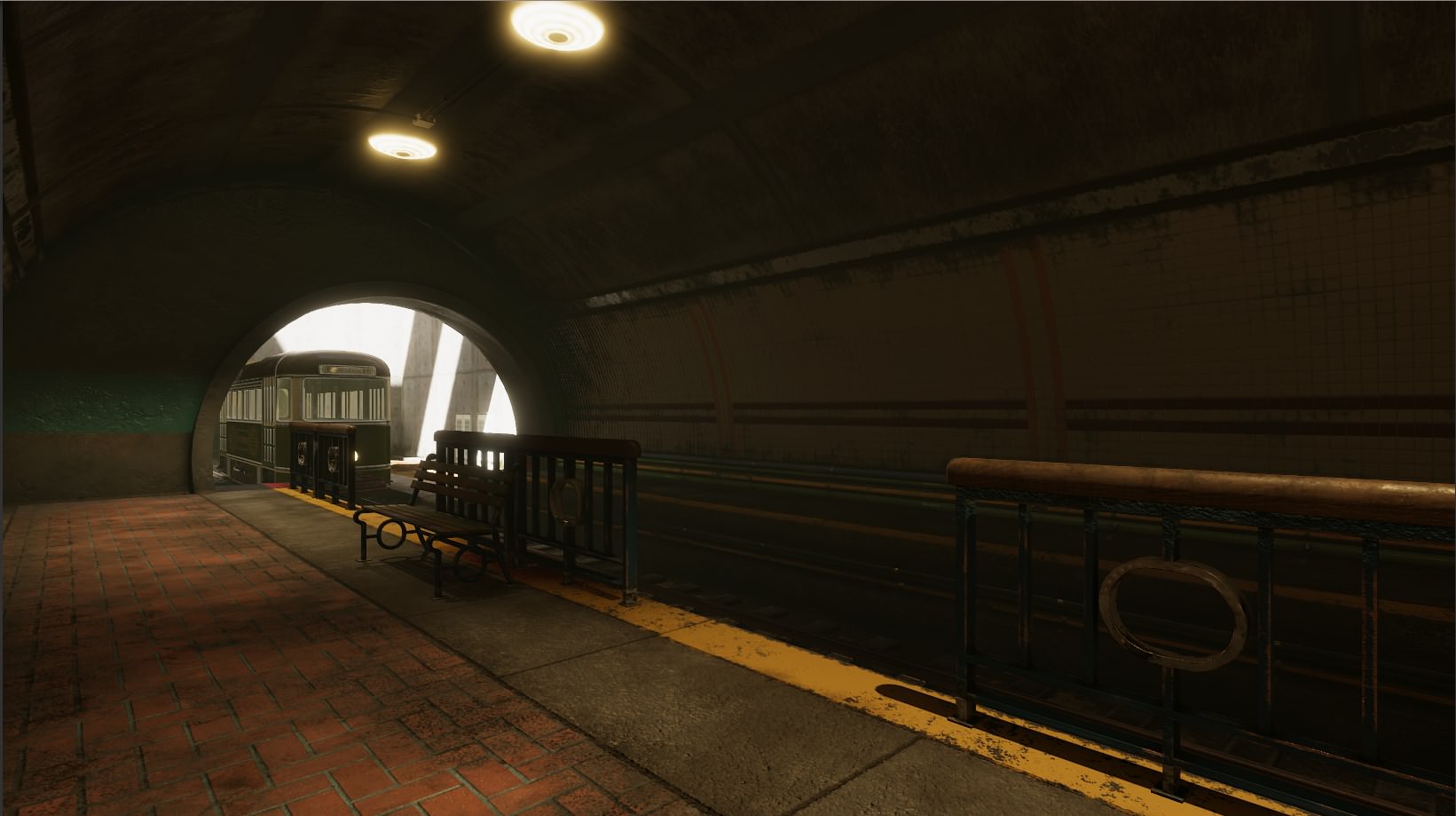
(and this was something Unity released in a sneaky place)
yeah there's a difference. but part of me likes the Std best
so it's not really fair comparison
HDRP seems like way too much i dunno, Fresnel 😛
you could make the built-in look better in that scene too
at least its the same scene/artist ive seen video comparisons not even using the same artist or scene
everything has a white edge around it
so dumb
yeah this is a comparison Unity hid in the documentation
it's totally different lighting on those two
so i didn't make any of it
but it's the closest comparison i have seen
well it has all the same lights in all the same places
that's why i say same lighting
but yeah their values may be dis-proportional
this is all going to be a pain to learn i think
there is one main thing that is going to look a lot different on built-in vs HDRP/LWRP and it's the dynamic lights falloff, built-in got errors on that which they can't fix because it would break backwards compatibility
but if you do baked lightmaps, that falloff is fixed even on built-in
to be honest, I don't really agree on the backwards compatibility excuse
you could just make a toggle for it
and it would solve that right away
(people could use the old way still)
but I do get that they don't want to keep updating the built-in renderer at this point
well nothing about HDRP is backward compatible
so i don't see why they would leave anything as such
yeah, I'm talking about built-in now
like, they could have fixed the light falloff on built-n if they had wanted to do so
in hdrp will we have to worry about making something on one platform and then writing solutions for it to work on another
shader throwback Saturday: http://web.engr.oregonstate.edu/~mjb/cs519/Projects/Papers/ShaderTricks.pdf
what was cool in 2006
i have the sea of thieves paper on their water tech
probably the worst paper ive read in a long time

@foggy agate you mean like a sonar effect?
https://www.youtube.com/watch?v=OKoNp2RqE9A try this as a starting point
to get the propogation of mesh
Oh god
That is exactly what I need... but I get 1/4 of what he is saying (dont know that much about shaders)
so I'll watch it a few dozen more times : P
Thanks @quaint grotto !!!
So, I have a fire shader that I made off a tutorial. Im trying to add an edge to it. So, I have applied a greater offset to a different version, which has successfully made a version which is slightly higher. I am hoping to use this as the edge, but I cant figure out how to mix them properly. Any ideas?
depends on the colour you want the edge
if you want it to work in any colour you kinda need masks of both
(well, your second one there is already a mask, youll just need to also make a mask of the first)
use blend nodes set to overwrite mode, with the mask as the input to Amount (or whatever its called)
ahh I kind of see what you mean. I will have a go!
luckily, my final products were just their previous maths (which is pretty mask like), with color applied. Looks good! Im going to work on making it only apply to the top now, but thanks so much for this @still orbit!
glad to help 😃
https://twitter.com/DomFeargrieve/status/1096554374107709440
Only just starting out but vertex displacement is awesome fun 😄

Still having a lot of fun with shaders, this time vertex displacement thanks to @unity3d and their amazing shader graph https://t.co/3mPKoyMVYG #madewithunity #unity3d #gamedev https://t.co/unJXnnpc3c
Hey all, so it's easy to do a shader that lerps between values based on world or vertex local height, but is it possible to have variations in that height? So that the line of cutoff wasn't uniformly straight?
sure. one good way would be to provide it with a noise texture, and add it to the height for the blend calculations
needs to be a gradual noise texture, not random. such as a height map.
you can use the world XZ as coordinates within the noise texture.
Thank you as you replied I was trying to implement it using a random noise texture. Could you clarify why generated wouldn't work?
A random (white noise) texture would have adjacent pixels jumping all over the place. for example, one pixel would have the value of 0.5, then next one would have the value of 1, and the next 0. That would mean that your blend line would be jumping up and down all over the place.
Now if you use a gradient noise map, such as perlin noise, the values would not jump from 0 to 1, but will gradually increase from 0 to 1, creating a nice, connected line in your blend.
This is what the height values in adjacent pixels look like in both options:
Generating perlin height map is very easy:
        public static float[,] GeneratePerlinMap(int sizeX, int sizeY, float frequency, RandomGenerator random = null) {
            if (random == null) {
                random = new RandomGenerator();
            }

            // choose area in map
            float startX = random.GetRandomValue() * 1000f;
            float startY = random.GetRandomValue() * 1000f;


            float[,] result = new float[sizeX, sizeY];
            for (int x = 0; x < sizeX; x++) {
                for (int y = 0; y < sizeY; y++) {
                    float perlinX = startX + (float)x / (float)sizeX * frequency;
                    float perlinY = startY + (float)y / (float)sizeY * frequency;
                    result[x, y] = Mathf.PerlinNoise(perlinX, perlinY);
                }
            }
            return result;
        }
(just use Random.value instead of my custom RandomGenerator)
https://gyazo.com/9f0970ae9e98d1e5fa5eeb0ea5545acc I think I'm quite satisfied with the random noise as well, thank you! I'm using Amplify and just used simplex noise generator 2D, remapped the values a little and it works as I wanted!
simplex is very similar to perlin. It's not random.
this is what random noise looks like (also called white noise):
This is what simples/perline and other heightmap noises look like:
you can see the difference, where one has a pattern of gradual color changes where the other is just plain random, with huge jumps between white and black
but anyway glad you got it to work like you wanted
How to easily write shaders for VR/AR?I am working on an AR/VR project. The VR part is basically to show the idea in a virtual environment (with the use of Google Cardboard) , before porting it to the Microsoft Hololens (I have access to Hololens only once a month, a the current unit is experiencing some issues). I'd like to create shaders using shader graph but I decided it is best to work on the LTS (2017.4) version, which has no support for shader graph, but works best with the SDKs (MRTK and Cardboard SDK) and recommended by Google and MS. I imagine simply copying the code from 2018.2+ won't work, so I am looking for something else (Shader Forge in mind). I have issues understanding the whole thing with LWRP as I don't get it to work, unless I download a pre-made UT package.
there's a page here about how to add VR to shaders
it's mostly about modifying the view transform for each pass (two eyes)
or probably more correctly, the screen space coodinatse
Thanks for the docs, but the feature lists only PC and PS4 VR, the CardboardSDK is for Android.
Use LWRP for VR
it will come with shader graph and shaders so it will be harder for you to ruin performance
There's a version for VR/AR
^ this
Use the VR template - it has the same content (shaders etc) as regular lwrp, but some VR settings enabled. And you can use Shader graph.
does LWRP work with MRTK and cardboard SDK? because that's his application.
I have been trying my hand at making a stylized water shader with the shader graph. From what I understand I want to get the camera depth texture. But it seems to be not possible right now? Is this true?
I'm on 2018.3.4f1 and SG 4.9.0.
@echo badger it does work on HDRP at least, haven't tried LWRP in ages
also, you know this post? https://blogs.unity3d.com/2018/10/05/art-that-moves-creating-animated-materials-with-shader-graph/

Unity Technologies Blog
In Unity 2018.2 we added the “Vertex Position” input to Shader Graph, allowing you to adjust and animate your meshes. In this blog post, I’ll demonstrate h...
there is "Scene Depth" node
oh, is that the same?
Hmm, okay. This post is a bit confusing to me https://forum.unity.com/threads/feedback-wanted-shader-graph.511960/page-30#post-3798496
Unity Forum
Hello, is not possible to use Decal in shader graph material right?.
I don't see the toggle "Enable Decal" in the shader graph.
It will take too long...
that shouldnt be necessary at all...
Shader Graph Blackboard is throwing this, so Shader Graph is literally unusable
Unity v2019.1.0b3
HDRP v5.3.1
Unreal has a "Bump Offset" node, i'm curious if anyone knows, does Shadergraph have something similar, or reference to how one would implement something similar?
from what i read here, it's a similar concept to parallax but not really the same
nevermind, i found a thread on the subject, here in case anyone is curious. I can probably just replicate the node myself: https://forum.unity.com/threads/bump-offset-parallax-mapping-window-shader.407091/

Unity Forum
Hi, I'm trying to write a window shader that offsets an interior texture based on viewing angle.
Here is an example of how to do this in unreal:...
Yep, just use tangent space view dir like bgolus says

reticle is a bit hard to see in the gif, but this is what i made, simulates how a RDS sight works
hey @urban breach just wanted to know if you had any luck with how to create the XRay effect from the Spaceship demo?
does anyone know how to do a procedural scanline? Most of the tuts that I have seen seem to use a pregenerated texture. My idea so far was to get the uv, split by y, and tile the output, but that doesnt seem to be working. Ideas?
heya, anyone got any pointers on using the depth texture in orthographic perspective?
I can get the texture, but when I map it on to a quad it fades in the z axis (I guess as it should) but I'd like this to be a linnear color and map vertical depth
...trying to add a foam effect to a water shader
cant answer that ^ but I can say that for anyone looking for an answer to mine, you can just use tiling + checkerboard with 0 x. Then just offset the tile to make it move 😃
The more I look in to it the more it seems not so. But is it feasible to make stylized water shader with shader graph and HDRP?
theoretically you should be able to make any kind of shader with shadergraph

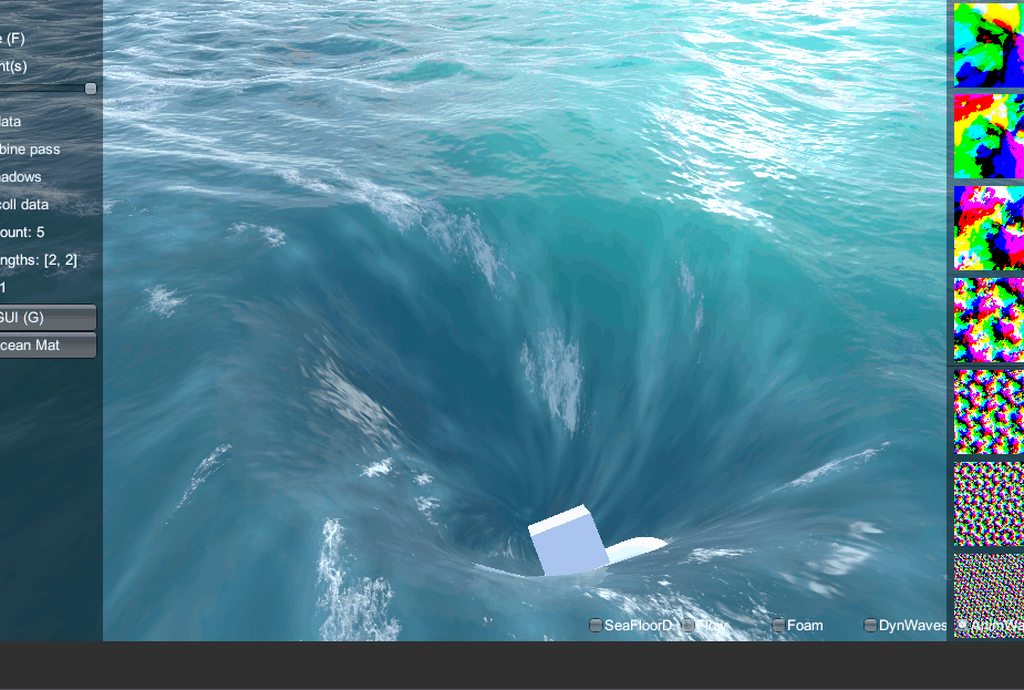
this sample unity project is made on LWRP and does pretty nice water
@frigid zinc thats not true
I beg to differ
anything with even remotely difficult math algorithms
Shadergraph is purely generic
is not going to happen in shader graph
you can make anything with it
ok make me a FFT ocean
it's being done
you cant make an outline shader. Just sayin
bet the math won't hold up
the maker of Crest ocean is making a LWRP version to start out, then HDRP later
using shadergraph
look for yourself heh https://github.com/huwb/crest-oceanrender

GitHub
An advanced ocean system implemented in Unity3D. Contribute to huwb/crest-oceanrender development by creating an account on GitHub.
just because something is hard doesn't make it impossible
@frigid zinc that boat demo uses extended LWRP for that water
Crest uses Gerstner waves, I don't know if that qualifies as FFT but if not it's probably better than FFT 😛
that does not lol
also afaik FFT has always been considered higher fidelity approach to ocean than Gerstner waves
gerstner is simple sine ways with exponential
well Gerstner looks mighty fine to me
people use it as it's simple and cheap
the arguement was if it was do able in shadergraph not what looks good enough
i dont think shadergraph can do FFT because its not a simple algorithm
thats a flow graph
it's an ocean system
well that's neither here nor there
no its not
you said you can do anything in shader graph i asked about FFT you then replied with an unrelated approach
yes it is, trying to use one edge case to make a blanket statement is ridiculous
I thought this discussion was done like day or two ago 😄
fft is not edge case
Sir has been asking for FFT on SG for a long time already
especially when the guy asked about making stylized water
not realistic water to begin with
there can be many types of stylistic waters :p
you made the claim that shadergraph can do literally anything. i disputed that saying FFT would be difficult
aswell as any advanced math algorithms
yes and they don't require FFT
but your claim was ... anything
you can't just argue out of the blue what others projects need
ceebee: you can make anything with it
so it's a bit ridiculous to say you can't do stylized water just because you believe someone can't do FFT on shadergraph
it can do anything, its open source 😉
i was disputing that claim
WHICH isn't even proven
lol
i was saying you can't make anything with it
well, all node graph editors have pretty big limitations when you go to more custom code, especially if you need more passes or compute stuff
exactly ^
dismissing that is just silly
they are limited
limitations are just something to overcome
no but dont tell people you can make literally anything in shadergraph thats silly and misleading
they aren't roadblocks
I mean, these are great tools, they simplify a lot of tasks but one key thing is to acknowledge the limitations of the tools so you can work around them
i'm fine with that, I didn't ask about FFT to begin with
shadergraph can do a lot but it can't do everything
that's someone else's obsession 😛
nope 😛
but yes you can do good stylised water in SG
why can't you just agree that everyone has right to their own opinions? :p
but FFT is complex, write the code 😛
you are just wasting each others time with pointless argument
everyone is yes
i have the time
😄
but doesn't mean I have to agree necessarily heh
var points = {};
I hate cmake with passion
please 😉

yes it's pretty
lacks SSS atm
I have still yet to see any open source project that makes cmake work out of the box for me
but not stylized 😛
its also incredibly expensive 😛
well, expect for bullet I guess
for example Sea of Thieves spent half its budget on FFT
your GPU still does the work
yes, its still expensive
i have the sea of thieves paper
@fervent tinsel sure but not linearly like a cpu
its all unrolled
yeah i know
need them next gen consoles
@still orbit any chance you could explain what your doing for orthographic depth in your ToonShading water shader?
it sure is pretty though ❤
but fine, I will concede, you can't make any kind of shader. I retract my blanket statement
but you can make water 😛
@random meadow I dont do orthographic. I generate world position from depth.
@random meadow how does orthographic depth texture work =/
since theres no real visual concept of a depth
re: stylized water, this is what I meant it can mean very different things to different projects needs:
yeah that's one type
oh sure thats definately do-able in shadergraph

GitHub
A collection of "Toon" shaders for Unity based on a stepped PBR approximation. - Kink3d/ToonShading
^ this is the function
@still orbit oh ok
yeah
i've been looking at it all morning
I'm trying to add some foam to water in ortho perspective
why ortho? what are you trying to do?
becuase my game is ortho
ah lol
😉
well at least that makes some sense 😛
whats the camera angle if its ortho? side? top? isometric?
3/4

They whisper her name on the streets: Solares. A mysterious veteran of the Data Wars, she keeps the fight against the Corporations alive as a vigilante hacke...
like that
helpful thanks
I can kinda get the depth texture and project it on to a plane, but it's not quite right
ah i see the water there
show me the depth on a plane
perspective view looks correct: https://www.dropbox.com/s/2fnzhuh8xd04wbq/Screenshot 2019-02-19 10.23.33.png?dl=0

but ortho isn't quite right: https://www.dropbox.com/s/fyszg8nzsbnwdfb/Screenshot 2019-02-19 10.23.08.png?dl=0

it's almost there, but the depth on the plane fades in the z axis (as it should without any alteration)
I've been looking at your water shader and this image effects one (https://bitbucket.org/Unity-Technologies/cinematic-image-effects/src/ceaa12aa06b0c4e055eaaea0a967384abfe15d6d/UnityProject/Assets/Standard Assets/Effects/AmbientOcclusion/Resources/AmbientOcclusion.cginc?fileviewer=file-view-default#AmbientOcclusion.cginc-124) but can't quite figure out how to get it right
I guess I should have specified. Right now I am just trying to get a intersect line to work (Shore line). Or depth, but am unable to get either to work.
what you mean by intersect line ? foam ?
you sure you cant use a second camera as perspective then linearize the depth texture from that and hopefully its close enough to not notice
@quaint grotto me or @echo badger ?
who ever is stuck with orphographic depth textures
oh, me then
hmmm, i guess that would work
just feels like i'm missing some kind of transform on the depth though, rather than something that complicated
well my immediate asusmption was that youre doing linear depth
idk maybe you are? idk what the amplify scene depth node does
Nope, not linear. it has a checkbox
i'm doing "Eye space" (not 0-1 mapping) and non-linear
well eye space will also be wrong in ortho
oh
ok
you need linear depth
it will be linear by default, its ortho
ortho is already linear
youll have to manually remap it to the clip planes if you want 0-1 tho
i wasnt aware depth textures work in ortho
yea they do
but if thats the case whats the issue =/
I think the issue is that i need to map the depth texture onto water plane
in fragment its already mapped if you use tex2d proj function
if i had to guess
he needs to get depth relative to water plane
rather than relative to camera position which is what the depth texture has
dunno . vague details so far
have you tried switching the screen depth out of eye space for funsies?
my debug method when I’ve double checked my math is to just check and un check all the settings lol
ok, got that mapping the depth onto the plane, but it's still fading in the z axis

I’m a bit tired so this May be dumb but I wonder what happens if you subtract screen pos.y instead of w
nothing 🤷
is amplify screenPos.z just clipPos.z?
yeah pos.w didn’t seem right lol
well screenPos is clipPos.xyz / clipPos.w right
dont use clip use screen
but in vertex
float depth = tex2Dproj(_CameraDepthTexture, i.screenPos ).r;
float trueDepth = (depth - i.screenPos.z)
tex2Dproj will divide by w for you
yea but in that example Sir, screenPos.z is clipPos.z
no its not
how is it not?
because in vertex shader:
i.screenPos = ComputeScreenPos(i.vertClipPos);
COMPUTE_EYEDEPTH(i.screenPos.z);
COMPUTE_EYEDEPTH is not happening

GitHub
Unity Built in Shaders. Contribute to TwoTailsGames/Unity-Built-in-Shaders development by creating an account on GitHub.
the shader is generated by amplify
^ ZW is untouched from clip space
oh your doing it in amplify
@still orbit well sure but thats why i use tex2d proj for the w and use compute eye depth on z

should it be normalized or not
i dont use editors so i cant help you with assets
Ah ok, this mess is why we dont do it like this anymore
its so pointlessly confusing
i'm happy to poke in the code and then figure out the amplify version later
its still actively developed
i see
yeah, it's actively updated
wonder how well they will sell with shadergraph which is free
probably still doing fine for now, we are missing some fairly important features
well at the moment amplify works and shader graph + lwrp is super not production ready
yeah, i need stencils which are still missing from shader forge
graph*
they are adding HDRP/LWRP support, so i expect they will keep going
yoooooooo
though they are only supporting them via templates
hmm

-UnityObjectToViewPos( v.vertex ).z
there's an object to view pos node
that is SO dirty
so shouldn't be too hard then
SO SO SO dirty
hehe
treating clip pos as object space
then converting to world and then view
I need a shower
oooooh
I misread
its a replacement
weird macro
replace screenPos.z with -positionViewDir.z
ok
#define COMPUTE_EYEDEPTH(o) o = -UnityObjectToViewPos( v.vertex ).z
this is the macro, weird one
that’s.. a couple conversions
isnt it lovely 😛
hang on, so what do i want?
and wow im so tired, its view space position
you need view space position
.z ...flipped
-UnityObjectToViewPos( v.vertex ).z < so this should be correct?
why negative?
because viewspace is object > camera
yes, it does, trust me 😛
ok, think i'm gonn have to write a custom node for that
ive not read how its done in SRP yet
you already have one in your graph 😃
wait what are you doing 😛
oop my bad that's screen depth you already have
surface depth yeah
screenshot type is tiny for my old eyes
why cant you use screen space since you already have it ?
hm, how do you do code inline in discord?
😃
thanks so much guys!
that was killing me!!
a fair few pips above my knowledge of 3d/shaders, so doubt i'd have ever got there on my own
haha
ah ticks
lol yea
isn’t it just md formatting?
sorry, i was being lazy tbh, should have just googled
should be md then
i learnt a lot! I just don't understand half of it
time to go read some things
seriously though, thanks folks, i'm super happy with that!
it is markdown
hey guys, my old "put world space UI on top of everything else" shader was broken by LWRP. Does anyone know where I can find a working one?
@quaint grotto Amplify supports classic unity render pipeline so that's enough for them to maintain development. Last I heard, ShaderGraph had no plans to support old pipeline, only LWRP/HDRP, unless things have changed.
^ Still true.
gentlemen. i require knowledge of shader graph
how can i make a material move (or extrude) a tiny bit closer to the camera? i am trying some decal work
Where you would traditionally move the vertex position along its normal, move it along the view direction vector instead
that is what i am trying to do
lemme just check for you before i give advice
@brave tinsel worth noting that since you want that for decals, there's specific decal graph on recent HDRP's
unless, you just want to do decal like stuff without using decal functionality
but i need something that can wrap. projection does not work great ;(
I thought you could do mesh decals too
but I admit I haven't tried these things myself
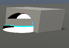
Yea so this "works"
but it depends on your use case
(the grey there is a cube in equal size of X, Z to the red cube)
cool. i replaced view direction with camera direction and now the thing is being pulled out towards me a tiny bit to negate the z fighting
now i need to reflect on how it runs and learn from it. thanks
Fwiw camera direction is just the opposite of view direction 😃
it got stuck on one axis for some reason. maybe because its all working in object space 🤔
you might need to do all the calculations in world space then convert the result back to object
I am having a lot of trouble getting an intersect shader to work in Shader Graph (Like what you would see on a shield or water shader). I was wondering if someone could help me out? Weather that be a tutorial, example project, or just showing me how you get that data. I would really appreciate it 😃
theres a number of ways to do it
I linked this yesterday but:
GitHub
A collection of "Toon" shaders for Unity based on a stepped PBR approximation. - Kink3d/ToonShading
In my water I converted the depth buffer to work space and used that for intersection
you can also do it by just testing fragemnt depth (clipPos.z) against linear depth buffer
@echo badger did you see this? https://forum.unity.com/threads/feedback-wanted-shader-graph.511960/page-38#post-4177540
(I'm rizu on the forums)
also I have no idea if that's doing some extra things, half of that isn't even my own graph
you can skip the double sided if you don't need it to show on both sides of the mesh
in the graph, there was multiplication with far plane
that's not needed?
that was part of the code I just copied from other user (noted on the post)
ah
oh okay. Yeah I say that and tried to copy it one for one. But I get this https://i.imgur.com/PIRTS2A.png
so, one could just omit that multiplication
what RP are you in?
also worth noting I didn't put safety clamps on the pows, so you may get something that isn't in range of 0-1 for alpha
I am on HD
yeah, but there was some issue on earlier HDRP versions for depth node afaik
HDRP had a bug where depth returned the entire pyramid
I am on HDRP 4.9.0 and SG 4.9.0
Entire pyramid? Isn't that like 3 of the same image and each one smaller or something?
What the heck.... i just double checked and it is not on 4.9!? I specifically downloaded 4.9 just last night.....
let me upgrade and try it then :/
hmmmm, I checked the far plane thing, it is needed when scene depth node is set to linear01 but not when the node is set for "Eye"
this works for example:
docs say "Depth converted to eye space units"
what is eye space? 😄
is this like for VR ?
Okay so I ended up just making a new project. But it does work now! 😄
Though it does have an error of pow(f, e) will not work for negative f, use abs(f) or conditionally handle negative values if you expect them
yeah, it's just a warning
you can abs it if you want to but it's really pointless if you just limit the properties input scale itself
and I don't think SG monitors the limits set there so the warning gets sent anyway
but that clamp (which I had on the image I just posted as last node) would be nice failsafe as you can get way out of 0-1 range with those pow values
Okay, that is what I figured.
I don't get that warning myself on my finished graph but I do remember seeing it at some stage
I am going to mess around with it now in a new shader to see if I can now piece together an idea of what it is all actually doing 😛
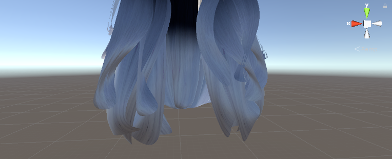
Hi! I'm working on a multi-purpose shader for my game, it allows a coat of metal on the albedo, and to get "inked" (covered by colored ink, basically)
I'm also trying to implement a decent "fade effect" / semi transparency version for stuff like hair and torn capes. But when that happens, anything under alpha / transparent parts is like "erased" here,
Anything I can do to fix that?
pretty much what I covered in #archived-works-in-progress relating to hair. the shader she pointed out would generally fix that, it's an alpha layering issue.
there's a name for what the shader does but I really can't remember the name of the top of my head
Unity Forum
Genesis Hair Shader
This was part of my Community Initiative to give very high quality easy to integrate products to the Unity Community for Free....
there's a free example here
though as I recall when I tried it, it wasn't the best

GitHub
A hair shader for Unity 5 originally built for the sine.space virtual world - AdamFrisby/UnityHairShader
this is another free example, but looks a lot better. it's nearly as good as the 20 dollar one on the store.
has that nice Anisotropic highlighting
(I got Fresnel on the brain now)
I'm looking at the source now, I kinda want to implement it in my own shader.
i think Adam's touches on what they do in the description
We render the lower pass using alpha testing versus blending; this fixes a host of issues with ordering; it's a little smelly, but it works better over all.
basically one pass is alpha test, and the other is alpha blend
so you kind of get the benefits of both
it is a bit of a hack but that's what most hair shaders do to avoid layering issues
That is definitely the recommended route yes
I havent looked at Adam's code but does he clip at a higher threshold then test the blend against the clip?
that way you dont overdraw, and only just the very edge pixels with blend
Also shameless plug, if you want a simpler version of the BSDF Adam uses there its based on my Aniso shader https://github.com/Kink3d/AnisotropicStandardShader
GitHub
A modified version of Unity's Standard Shader using an Anisotropic GGX BRDF. - Kink3d/AnisotropicStandardShader
Yeah i noticed he mentioned he used it in the description 😃
i got both of those months ago, they are somewhere in my bottomless bag of shader stuff lol
And no I don't see he uses that technique, it sounds like a good idea.
would you just use clip() to do that, or another technique?
yea discard like you would with any alphaclip, but do it at a slightly higher threshold so you discard a few extra pixels on the edge
like when you contract selection in photoshop to feather the edge of a rasterized shape
makes sense, cool
then do a custom depth test of the blend, with a tiny offset so it fails against the clipped one 😃
other yea, youll get a tonne of overdraw
I wonder if the 20 dollar shader does that, now i'll have to check hah
it does hehe, that guy is pretty clever

he has two thresholds so you can tweak both levels
actually i'm not sure what he is doing with the second
does this look right
c.a = s.Alpha * step(_BlendAlphaCut, s.Alpha) ;
oh i see, yeah that's his 'clip'
so the way he's doing it it still draws just either opaque or transparent....
doesn't really save overdraw at all does it?
yeah i will have to fix this heh
you want to get it to fail the depth test
unless hes doing that also, and that later code is redundant
he's implemented it as a surface shader and that's in the lighting function
ok i isee
in the surface function he has the clip
so that's unrelated
does it use the Offset feature described here: https://docs.unity3d.com/Manual/SL-CullAndDepth.html
if not its doing double draw
in one pass he does clip ( o.Alpha - _Cutoff );
and the other pass he does clip ( _Cutoff - o.Alpha );
so i think it's fine 😃
ergh, dirty
depth test offset is faster
and better design 😛
how bad that is depends on platform though
discard isnt cheap on mobile
yeah i don't see offset is used
that's neat about Offset, i hadn't read up on it before, looks super useful
there's still a lot i have to learn about shaders
offset is amazing for multipass stuff
completely off topic but While researching something today i found this tutorial on how to change Blender Icosphere into a hexasphere: https://blender.stackexchange.com/questions/67334/how-to-turn-my-honeycomb-pattern-into-the-sphere

Blender Stack Exchange
I'm new to bender and followed some tutorials. After following this one I'm trying to make the pattern I have into a ball. I can make the pattern follow a path, so it's probably not that hard to ma...
reminded me of the code from yesterday lol
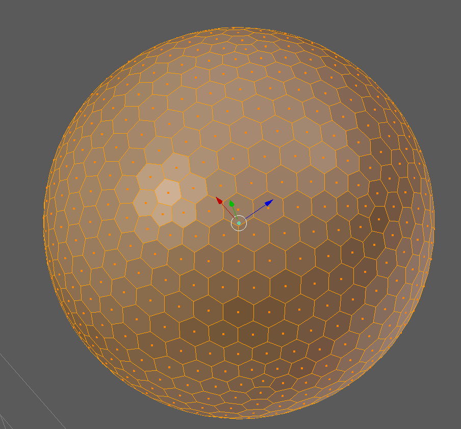
tried his technique and it worked
it's imperfect though, there are a few pentagons scattered about
BAHHHHHHHHH
you have no idea how annoying that is to me!!!
its a goldberg polyhedron and it has 12 pentagons regardless of subdivision. 😢
Hey guys, just checking in once more to see if anyone has a working "World UI Text Render On Top" shader. Trying to modify Unity basic text shader, but am horrifically bad at actual shader coding.
which render pipeline?
LWRP, 2018.3
hmm tricky
youll need to take the LWRP Unlit and port the text specific stuff from the regular text shader onto it
i mean, i guess the default text shader should work, but its not recommended
true. I hadnt considered grabbing the source from LWRP. Its even better actually, because while the Text and TextDetail default shaders only specify materials with a fallback, LWRP/Unlit has all its bits in the one shader
yup
then you just need to port the text rendering specific stuff
which iirc isnt a lot
yeh, doesnt look too bad
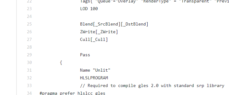
im sorry to impose, but I have tried to get this shader overlaying, and its being stubborn. It renders text properly when set to transparent, but is still behind my other objects. The file: https://gist.github.com/RarCeth/099bfe3cda6e00b541ce98d98567531e

i can't get it to work says it can't find "UnlitInput.hlsl"
yeah must be
i know how to do it for the standard pipeline but looking at LWRP i'm a bit confused.
but looks like they have it set to overlay and ZTest off, which is what you'd do for standard
so not sure why it would still be hidden behind objects
well i take that back, I don't see they turn ZTest off, only ZWrite
try setting ZTest Off
yeh, i got all its dependencies and copied them across. There were some weird settings for ztest etc, so I have now replaced them with ZTest Always, Cull Off and Blend[_SrcBlend][_DstBlend] (the last was theirs). It is now sitting on top, but is always black, no matter the color setting
which is what im warring against now 😛
For the dependency thing, I tried to add a new shader to the package, it didnt like that 😛
if you want it to render the text over top of everything, you want to set ZTest off, not ZTest always
or maybe i misunderstood what you're after
weirdly, it is currently overlaying everything else with its current setting. Could it be because I set Queue to overlay?
that's part of it yes
i don't see where you're setting Ztest in that shader
line 30
I just solved the color issue. changed texColor.rgb * _Color.rgb to have only _Color.rgb
line 30 has nothing but a bracket 😃
maybe you modified it since it was put on pastebin
but if you got it working all good
ahh yeh thatll get you every time
thank you both @still orbit and @frigid zinc for your help 😃
well i didn't do much but glad you got it working 😃
haha its always helpful to bounce ideas, and you gave me the idea to use the lwrp unlit Kink 😃
for interests sake, I ended up getting a problem with text disappearing after this. Overlay + 1 doesnt like the Mask component. Instead of masking it outside of the area, it just masked it everywhere. All good, everythings just on Overlay now 😃
thats probably hardcoded Unity voodoo magic lol
Hey guys, I have a question about making fog of war for lower camera angles. Right now, I have a separate camera and a "view radius" around every unit, which creates a RenderTexture that shows which parts of the screen should be fogged, and which shouldn't.
Then I render the game image itself without fog of war
And finally, I render the fog of war, masked by the "view" are image
The problem is, as you can see, that objects that are within the fog of war are also cut out if they are tall enough, like that tree.
Any ideas on how to solve this in a well-performing way?
maybe cull by distance if its a circle
Hmm, it's many circles, there can be many units that reveal the fog
most people use a mesh inbetween the camera and the land
maybe if you change the draw order =/
im guessing though at this point
Changing draw order won't work because I do want objects that are placed outside the fog area to be hidden
A mesh around these circles could work, but it would add a lot of vertices/tris to the scene, and also create a vert sharp edge. The best would be to use actual fog for a more gradual edge, but that would kill performance the way I know it.
The solution would be in the stencil (your render texture) rendering . You want the tree to be rendered white, because it's within X distance of your unit. I'm not sure if this is the cheapest way to do it, but in your second camera rendering shader's vertex function you could get the horizontal distance from the unit and tell the fragment shader to render white if it's within range of some player unit.
That would mean passing data to the sader about hundreds of units, and checking against each one...
I'm not sure how you'd check against multiple player units inside the shader. Another technique that i remember reading about ages ago, you create a stencil rendertexture of a top-down 2D view of your playfield with white circles representing the radius around player characters. That 2D texture represents your playfield, so the fog rendering camera can get the world position of each vertex and compare the x and z values of that world position against the top-down stencil texture
It only works for 2D, and the scale of the stencil texture would depend on how big your playfield is
Hmm, if I pass the vision texture of the entire world from a top-down orthographic view to the 3D object shader, I could multiply each pixel by the value in the vision texture using that pixel's world XZ. That would work in 3D too.
i would try making the fog of war mask top orthographic from above and then in the units shader don't draw any thing unless the center of the object is within the white part of the mask
I wonder if I could do it in post-processing somehow, save a buffer of the world XZ of every pixel, and then in the post-processor add a fog depending on the XZ
that could work too. The tree would instead be cut in half i guess
which sounds pretty neat tbh
@last robin that's a good idea for hiding units in "discovered but not currently visible areas". But I still need to mask the terrain, objects, etc - too, in the undiscovered areas.
lol, yeah. Though I have a gradient so it would be smoother than that
i like what you were saying a line ago. Top down ortho mask, inside unit's shader discard if pos.xz is outside mask
question is - how do I get the XZ position of every pixel on the rendered texture...
one sec i think i have that somewhere
so this is actually done in a compute shader but it should be somewhat easily converted to an image effect
float4 GetWorldPos(uint3 id, float w, float h)
{
    float2 screenPos = float2(2.0f*id.x * (1.0f/w) - 1.0f,
    1.0f - 2.0f * id.y * (1.0f / h));
#if UNITY_UV_STARTS_AT_TOP
    screenPos.y = -screenPos.y;
#endif

    float4 worldPos = mul(_ScreenToWorld, float4(screenPos,0,1));
    worldPos /= worldPos.w;
    return worldPos;
}
called with this
Source.GetDimensions(w, h);
float2 currentWPos = GetWorldPos(id,w,h).xy;
supposed to be for xy but i think rotating the camera to point down will make it output xz
also somewhat of a warning i've never tested this on other machines
Matrix4x4 screenToWorld = (camera.projectionMatrix * camera.worldToCameraMatrix).inverse;
that's _ScreenToWorld. you gotta pass it in with a script
id is pixel position int from 1 to texture width/height. w and h is texture width/height
you can change that to use uvs in [0,1] range instead i'm sure
should™ just be changing float2 screenPos = float2(-1 + 2 * uv.x, 1 - 2 * uv.y)
Thanks, I'll check it out.
I think it may be a bit more complicated, because you can't interpolate world position from clip XY alone. You also need to get the Z from the depth buffer somehow.
any idea how to access the Z buffer from a shader? I wasn't able to.
i don't think depth matters with an orthographic camera
but you can use _CameraDepthTexture
I tried that, I just get 0 everywhere.
you have to make unity render to it with a script
Probably because it's a different camera
ok. I'll try reading up on that a bit
It's not an orthographical camera btw. the idea was to use orthographical top-down only to render the "viewable areas" texture, which you can then sample based on the "world XZ" position of every pixel on the screen.
i think it's just this Camera.main.depthTextureMode = DepthTextureMode.Depth;
oh you want world position of pixels in a post process effect?
Thanks!
with perspective?
yes
this video goes over that https://www.youtube.com/watch?v=OKoNp2RqE9A

Support me on Patreon ➜ https://www.patreon.com/DanMoran Follow me on the Twittersphere ➜ https://twitter.com/DanielJMoran Get the Assets for this Video here...
thanks again!
it seems so indeed
so, tried that. problem is to get something that looks good, we need a really large render-texture for the world-visibility thing...
but it is working rather nicely
Hi,
I have two transparent objects, and I want to hide one object behind the other
how can I go about achieving this?
I want the object behind to be fully occluded by the near object
i.e. you should not be able to see the lower half of the sphere (which is behind the cube)
(I already have a shader which does not render the backfaces, of the same object)
okay thanks
@light basin not sure I understand. If you want the object behind not to be visible - then it means that the object in front is NOT transparent. What am I missing?
Can someone help me figure this out? When I have no material set on my buttons, they automatically display the material for my tileset, even though it specifically says I do not have a material selected.
Setting the material to another material fixes the problem, but I want to know why not having a material is causing this bug.
Ah ok, so there are some objects you do want to see behind it, and others that you don't...
Yeah, Stencil sounds like the right way to go as Remy suggested
yeah that's correct. Thank you
So I have gotten my water shader to this point (Which doesn't look like a lot. But there were several different iterations trying different looks)
Now for the life of me I can't figure out how to color the black water. Now that I hooked up the depth part of it.
just apply a basic color first then apply the lighter colour on top when you have shallower depth
like a dark blue and just lighten it the more shallow it gets
you could use a lerp between dark and light blue with your depth values
I'm sorry, I can't figure out at what point to apply the color.
Would it be after the One Minus and before the Multiply?
you should have a black and white depth value
then lerp dark > light based on that
or better yet, sample a gradient based on that
Oh I see! Thank so much @still orbit!
you should totally sample a gradient based on the depth value, you could get some really cool looking things from it i think
ShaderLab shaders dont support gradient properties 😦
anyway, when youre happy with it, you should probably convert it to a texture instead
itll be faster
gradients are just really good for prototyping
How would one do that do you know?
You can sample a texture as a gradient by just sampling it at custom UVs instead of the UVs from your geometry. For instance, sampling a horizontal gradient image at UV (depth,0) will get you a sample of the gradient at the position you want.
isn't a simple lerp between two colors a more efficient operation than adding another texture sample?
though with a gradient texture the nice thing is you can swap out different non-linear gradients easily
yes a lerp is much faster, but with water colour it doesnt look very good
linear interp is not how transmission works ya know 😃
Of course, but chances are they're not making a gradient texture that matches water falloff either haha, but it can definitely help make some more artistically pleasing water for sure. I'd be interested in what the math would be for calculating the proper transmission/attenuation for a given depth, density and IOR would be though
is there not a option to encode the gradient data into a texture or a array of floats? i know super hacky but haveing no gradients from the inspector is not so nice.
They'd have to make a shaderlab attribute for texture properties to have a gradient color picker and the material editor generating a texture asset behind the scenes... doable but I can imagine it could introduce a lot of headaches for little gain to the average user. I'd just make a material editor extension for that if a team needed something like that. General approach seen has usually just been LUT inputs, easy enough for any artist to deal with
@still carbon probablc correct and runtime changes (what i would have used it for) are not that easy
Yeah, you'd be generating new textures at runtime when changes are made, though that's not bad if they're just small strip gradient textures. But if needing to keeping changing over frames I'd imagine it might be better to just have a few color/float inputs on your shader that calculate the gradient
i have to look into making a shadergraph node thats does take some float and color inputs and generats a gradient that can be chaged at runtime
well our gradient node is just that under the hood
a struct containing a bunch of vecs for the keys
when i end up making it so you can declare unifroms for them
ill probs make a C# script that can set that from a gradient field
pretty simple solution
Oh I hadn't looked at the grad node in SG, that's pretty nice
😃
its a nice representation, but its just a struct
which in fairness is what gradients are really
float4[] colorkeys
float2[] alphakeys
int mode
that's a nice idea to decouple the alpha gradient from the color, was surprised by that as you don't often see it
well thats how the gradient is represented in unity in C#
Is there anything exposed in non-package unity that used that gradient representation? I don't recall see controls like that in unity before
yea the shuriken particle system 😃
although the one in shader graph is UIElements, so not technically the same UI. But i think it works the same way.
Ahh that's why I hadn't seen it haha, I rarely delve into the particle system. I see it's using the same popup as the SG node, for color by speed and over lifetime
Absolute noob here... Does someone know a good source for blur-like shader?
hmm, for your normal script shaders, I would google terms such as 'unity hex bokeh shader'. I havent looked into it yet on SG, that could actually be an interesting next project
seems what I'm looking for times ten with the depth probably : )
I'll look into it thanks
all g 😃 good luck!
is there a way to name the outputs of a subgraph is SG?
Made a scanline maker, and would like to label outputs as "Main" and "Opacity"
🥂
That has bugged me as long as I've used sub graphs in SG :)
Oooh, custom function node too on the PR
GitHub
Purpose of this PR
Adds Custom Function Node
Refactors Subgraph Output Node to support all port types and renaming
Adds ReorderableSlotList View to handle the above two changes
Changes Convert To ...
hmmm i should get on that...
Wyatt pls
You too yo
Hi, could anyone help me in figuring out what this type of shader it is I'm looking for? I basically want the rectangle to be invisible, and only show the square that touches the body (on both sides)
You probably want to work with stencil here
Stencil it is. Thanks, I always get stuck figuring out what keywords I should search
@still orbit there's one breaking issue on the PR, I noticed it on the WIP branch too but thought it wasn't just finished: If you have multiple output ports on subgraph and you rename the first one, it messes up with the other ports
I think this only happens if you have old existing output ports in the subgraph. It totally messes up if I try to rename old, existing ports but if I remove them all and make new output ports, they work as expected
actually, it happens on newly made ones too if you restart the editor, it only works like it should in the session you make the outputs first time...
same issue exists on Custom Function's inputs too
i think this is because its technically removing and adding the port if you change anything about it
currently removing a port that has connected edges throws nulls and breaks the graph
if I disconnect all ports and rename it does work
however if I only disconnect the port I'm about to rename, it still messes it up
Yea ok, this is a known issue then 😃
Todays job is to fix that...
it needs to go in separate PR first, the current subgraph output node has the same bug, it just only reproduces one way because of how rigid the node is'
atm, is there any difference if you expose SG's Sub Graphs properties or not expose them?
I really can't tell what effect it has atm
I could swear it used to toggle port visibility for the subgraph node on the main graph but right now they show up anyway
there is no difference for exposing vs not exposing on a subgraph
is there any plan on being able to expose subgraph properties for c# access?
I'm now just routing things to main graph and setting things there but it's extra step
uuuh i don't think there's any plan for that right now no, since you'd have to putting the subgraph into a regular graph to use it anyway. if the extra step is a high user pain for a lot of people then maybe, but right now it's such a specific use case that other things are higher on the priority list afaik
yeah, curious about this since I know ASE can do this
so now if I want to have like that Occlusion Probes sampling subgraph, I can't just trivially throw it out there without explanations as the sub graph can't expose the needed properties
in ASE, I can do that in it's subgraph equivalent and all I get is nice and clean node on the main graph without anything extra to wire
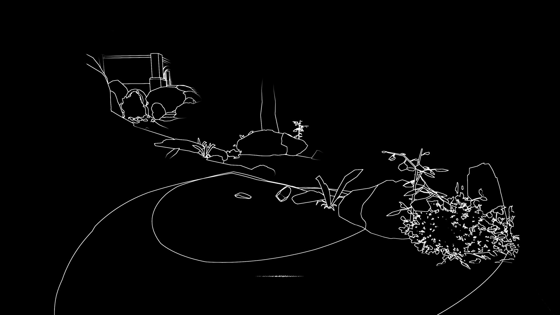
Hi, I have a scene that is made from depth-sorted SpriteRenderers. We're doing this because using 3D textures would make it look like a Playstation One game (ugly) so we would prefer to use isometric pixel art.
The art-team would like a glow effect on all of the objects to make it look like you are in a Tron-style VR environment. Here's a mockup:
I've said that because objects must be in front of each other, the glow would have to be applied in sequence on every sprite. Some objects will occlude others, meaning the glow on some objects will be partially visible.
Am I right?
I'm also not sure how I would go about writing a shader to do this to all of the sprites in depth-sorted sequence. If I'm wrong then perhaps I can just do a single pass on the camera output instead of every sprite.
yeah if you wanted that effect to be dynamic it might get tricky, but tbh depending on what they want it to look like i might be inclined to just "bake" the glow effect directly into the sprite texture
basically just like the mockup is done (i'm assuming) directly in photoshop, just use that in the actual sprite texture
fake the look real hard
The problem with glow on every object is that all of those alphas are going to get dirty when stacked on top. I believe the artist is expecting some kind of blend mode to be applied - but the game engine needs to depth sort in real time (I have the engine working fine with clean pixel art).
hmmm fair point on the alpha but i think you're going to hit a limitation of your asset method. it looks like the artist wants interior edge glow too but if you're just rendering flat pixel art, there's no edge data to feed into the shader. you'd need some kind of look up map for each object that tells the shader what the interior edge data is as well as the depth sorting...
Yeh - the thing that kills it is two cubes sitting next to each other - whose glow is in front? What if the depthsort swaps them?
yeah this is... not an easily problem to solve...
I'm mostly building a case for us to try a different direction with the art. I think people are cool with that, but I needed advice. I appreciate your input.
why not bake glow into another channel?
then you can just render all glow in a post effect pass
Any ETA to be able to define arrays of float and vector as properties to be accessed from c#, like in the built-in pipeline?
Now that we are going to be able to write full HLSL code with the new code function, and write loops on it, I think it is a functionality that we are going to miss.
@long lotus i'd think, for the case of the two cubes side by side, their glow contribution should just mix, no? Let them write their glow to the emission buffer and let post process bloom take care of the rest.
If you want to avoid making separate glow textures, then the less flexible option would be customizing the sprite shader to have a sort of "Emission Cutoff" value that you would multiply any values above that range by your emission intensity value on the shader. (and could clean up this effect by using a bit of a soft-step at the cutoff so it's smoother transitions to glow). This would allow you to use just one sprite, but you'd have to be aware of this when crafting the sprite colors.
@grim bane If youre using this in a custom function node, and are going to set this via C# anyway, you can define whatever unifrom types you like, including arrays and structs
Youll just need to define all this stuff in your HLSL include, along with your function
it wont be accessible via the graph
well add functionality for arrays in the graph, just not in the immediate future
Wow, great news!
the advantage of doing things via includes, do whatever you want in there 😛
does the hdrp make it any easier to make a render texture of objects below a plane ?
Actually it kind of does with a planar probe
I've not tested it upside down though
Maybe you mean something different though
isnt that for things above the plane not below ?
for me i need a render texture of things below my water plane
i know there is a way with matrix transform on camera but i can't understand it properly to use it
unity's code is painfully long and unexplained on what they are doing
yea planar projection, i assume HDRPs planar probe can go upside down?
Render screen to render texture with replacement shader that cuts objects off at water plane height, use Rt in your water shader?
nah you need an oblique projection matrix
I'm making a screen display shader using Amplify Shader Editor
Thanks, this is my first shader
Heres my video testing a shader function.
https://www.youtube.com/watch?v=lhoQwlR6DCI

Testing my new WIP shader function. https://www.artstation.com/ljf/profile https://twitter.com/PoorBoi_
For a planar projection yeah, I just meant in the context of what Sir is trying to make i'd imagine an RT from the same view but with just the underwater parts of meshes would be enough for his goal of creating some slight wave distortion on the surface for underwater parts only. I'm guessing a planar projection would be nice though for creating more convincing refraction? (just genuinely curious about this stuff, never dealt with oblique projection matrices)
oh sorry i wasnt actually paying attention <__<
yea draw underwater to offscreen RT then blit back against a stencil
@still orbit yeh oblique matrix but i dont understand it well docs kinda non existant no real tutorials on it either
Yea there isnt really 😦
@still carbon how would i ever get the underwater parts from the same view without it
some objects will be partially in the water too
its mix of example code of planar projection ....and then straight up maths docs on oblique matrices
@still orbit thats been my problem with unity for a long time, when you want to do specific things unity offers nothing in the way of working it out
well, this is getting better
i worry hdrp will be even more "figure it out" rather than actual helpful guides
is there a good doc on it ? need to check if it does reversed normal planar aswell
i need up normal for reflections, and down for refraction
HDRP is still preview and mostly undocumented im afraid
are the probes different in hdrp to lwrp ?
but im sure you can figure out if you can flip it pretty easily...
planar in LWRP isnt probes
its good old draw again to offscreen with oblique and blit to screen
well probes is a lot more than 2 renders xD
isnt that what unity's pro water already does ? at least from what i can figure out from the source
my friend wrote it, im going to go ahead and call it good 😛
there is always something they do which gives you a headache
remember they is you in this case
nah they always have something which is awkward to work out
niche things are often just a pain to solve
compute shader i can't work out well at all
you ever used them in unity?
oh you work there
well compute shaders is not easy to get into !
also do you know if hdrp planar stuff is reliable to use at the moment or am i likely to run into bugs
Hey guys! Coming back to this channel to see if someone has any idea of how to get a draw on top of everything shader within HDRP?