#Flyback SMPS burned some resistors

1 messages · Page 1 of 1 (latest)

weak steppe
#

So I'm working on this fan again. When I added the ESP32, I had to replace the 78L05 (TO-92) with a higher current rated LM7805 (TO-220). This worked fine for a few months, now I have two 150 ohm resistors that are burned up.
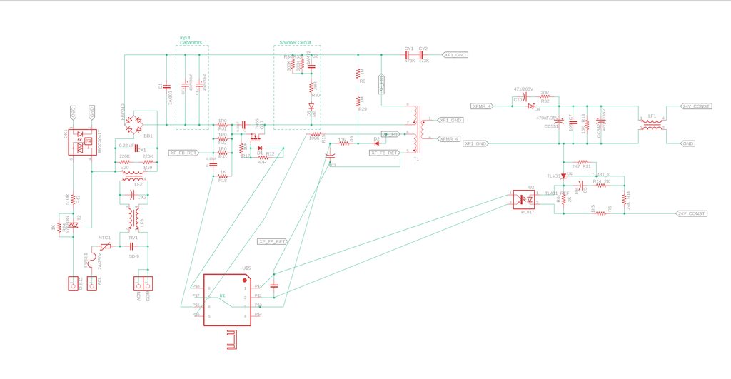
This board appears to utilize a flyback converter to supply 24V to operate the motor.
Once the 24V is supplied, it appears to use two 150 ohm resistors in parallel to drop the voltage down to 12V. This 12V is supplied to the input side of the LDO, which in turn outputs the 5V to the controller.

My question - I'm pretty sure these two 150 ohm resistors being burned up is a result of the new LDO pulling too many amps across what appears to be a simple resistive link. Does it make sense for 150 ohms to effectively lower a voltage from 24V to 12V? I've temporarily replaced with a single 2-watt THT resistor, and these are the voltages I"m probing before and after.
oak echo
# weak steppe

Hard to say what’s happening here, I’d guess that the two resistors was to double the path load current, one resistor failed causing the other to also fail. I don’t imagine they failed exactly the same time. But they would have dissipated something like 4W in a pretty small space

#

4W is a lot to put those resistors through

weak steppe
#

Yep, I figured it was the resistors overheating. I'm sure they were doubled up because one would probably get too hot on its own.
I was playing with a test circuit on falstad, it doesnt appear those resistors were specifically to drop voltage, although it could effectively lower voltage if you know the exact current draw of the downstream devices. More current draw would effectively lower the voltage to the downstream components

oak echo
#

Did it get pretty warm when it ran?

weak steppe
#

I had initially put it back together before I could notice anything abnormal. Although when I replaced the burnt resistors with a 150 ohm 2W THT, it got hot enough to melt the UV glue I had used to hold the wires in place

oak echo
#

Ah yeah, that makes sense

#

I suspect there is another culprit behind the failure

#

Possibly a short somewhere

weak steppe
#

All the downstream components appear to be working with the replaced resistors. I know that doesnt rule anything out.
I just had a thought - I could attach my benchtop power supply and see how much current the downstream components are pulling

#

Do you think I could effectively replace the LM7805 and 2x 150R resistors with an LM2596 buck board?

#

It'll handle the 24V input, and provide a 5V switched output @3A, effectively doing the same job

oak echo
#

Possibly, it would be good to see what your max draw is

#

A buck will definitely be a more efficient method of stepping down anyway

weak steppe
#

That LM7805 was powering a Wemos D1 Mini (esp32), the original MCU, a 2-digit 7 seg display, and a few buttons. I'm not expecting the current draw to be that high

#

I did a full reverse engineer on this board, that's why the schematic looks like crap

oak echo
#

No worries, anyway buck converter is always a good choice if you’re stepping down from 24V to 5V

weak steppe
#

sweet, let's see how that turns out