#help-with-arduino
1 messages · Page 83 of 1
 cedar mountain
 pine bramble
Oh
 reef ravine
this is a good state machine example for buttons https://www.arduino.cc/en/Tutorial/BuiltInExamples/StateChangeDetection
pine bramble
Thank you, I'll see what I can get based upon that
 rose gate
hello. I need some serious help with my arduino
just opened it up for the first time today.
connected it to my PC, downloaded the latest software, and boom. I still need drivers
so I troubleshoot it and finally get it to work
but, no dice!
Arduino: 1.8.13 (Windows 10), Board: "Arduino Mega or Mega 2560, ATmega2560 (Mega 2560)"
Sketch uses 1536 bytes (0%) of program storage space. Maximum is 253952 bytes.
Global variables use 9 bytes (0%) of dynamic memory, leaving 8183 bytes for local variables. Maximum is 8192 bytes.
C:\Program Files (x86)\Arduino\hardware\tools\avr/bin/avrdude -CC:\Program Files (x86)\Arduino\hardware\tools\avr/etc/avrdude.conf -v -patmega2560 -cwiring -PCOM3 -b115200 -D -Uflash:w:C:\Users\Admin\AppData\Local\Temp\arduino_build_556528/Blink.ino.hex:i
avrdude: Version 6.3-20190619
     Copyright (c) 2000-2005 Brian Dean, http://www.bdmicro.com/

     Copyright (c) 2007-2014 Joerg Wunsch


     System wide configuration file is "C:\Program Files (x86)\Arduino\hardware\tools\avr/etc/avrdude.conf"


     Using Port                    : COM3

     Using Programmer              : wiring

     Overriding Baud Rate          : 115200
avrdude: stk500v2_ReceiveMessage(): timeout
avrdude: stk500v2_ReceiveMessage(): timeout
avrdude: stk500v2_ReceiveMessage(): timeout
avrdude: stk500v2_ReceiveMessage(): timeout
avrdude: stk500v2_ReceiveMessage(): timeout
avrdude: stk500v2_ReceiveMessage(): timeout
avrdude: stk500v2_getsync(): timeout communicating with programmer
avrdude done. Thank you.
An error occurred while uploading the sketch
This report would have more information with
"Show verbose output during compilation"
option enabled in File -> Preferences.
BDMICRO, LLC
Delivering 32-bit ARM Cortex, Atmel AVR, ATmega128, ATmega2560 Microntrollers, SAMD21, SAMD51, Relay Control, Optical Isolation and Isolators, H-Bridge Motor Control, Robotics, Automation, IoT (Internet of Things), Electronics, DIY, Industrial Automation, since 2002. Author of...
its not communicating!
with the programmer
I connected it to com3 which is the only port that I can choose
So whats the deal?
cedar mountain
What type of board do you have?
 proven tusk
Can someone help me with a project where an lcd screen displays a timer and a press of a button starts the timer. The LCD screen has 20 pins and is 128 x 64. I need help with setting it up and the code. If anyone wishes to dm me to offer to help, i would gladly appreciate it. I am offering to pay too.
rose gate
@cedar mountain Mega 2560
 zealous cosmos
@zealous cosmos - I just updated the gist again --- this time without the extra delays --- but added a debouncer class. This runs nicely on my CPE device (even types your characters!)
@obtuse spruce Amazing results on the toggled buttons. The color alternates on every single click (button). Good there. However, the emulated hotkeys happen when I click the button Twice. It should be Once. I think you almost nailed it. It's so close. Please advise. Thank you so much for your valuable time. - Tan
 obtuse spruce
Just take out the if that surrounds the hotkey bits
zealous cosmos
Just take out the
ifthat surrounds the hotkey bits
@obtuse spruce I took them out like you said and it works PERFECTLY! Very nice! Thank you. Here is a new request. How do I code so that the neopixels gradually dim down to 20% within 5 seconds after pressing each button?
The 100% brightness of the neopixels can blind my eyes.
zealous cosmos
This list https://www.arduino.cc/en/Reference/KeyboardModifiers does not have the key for the COMMAND key of the MacBook. I'd guess the ALT key on Windows keyboard is similar to the COMMAND key of Mac keyboard so I tried KEY_LEFT_GUI or KEY_LEFT_ALT. Neither one of them works on the MacBook. Does anyone have any suggestion? Please advise. Thank you very much for your time.
Open-source electronic prototyping platform enabling users to create interactive electronic objects.
 elder hare
is there anything i can do better / i can optimize / clean up this class?
MySocket.cpp -> https://hastebin.com/dikuhihadu.cpp
MySocket.h -> https://hastebin.com/egilihabig.cpp
MySocketStrip.h -> https://hastebin.com/ilinazonek.cpp
zealous cosmos
Just take out the
ifthat surrounds the hotkey bits
@obtuse spruce Without the third button, so I added a new 'if' condition for triggering a combined and "derived" button action while pressing both physical LEFT and RIGHT buttons at the same time. Without success, using the '&&' token as follows. Please advise. Thank you so much!
if (rightButton.pressed() && leftButton.pressed()) {
Keyboard.press(altKey);
Keyboard.press('q');
delay(100);
Keyboard.releaseAll();
delay(100);
}
 tepid blade
Hello! I have a problem with my arduino connected to my ESP8266 and Adafruit. When I send a signal to the arduino sometimes it response and sometimes it doesn't. The ESP8266 is set in 115200 bauds. Can it be the source of the problem?
 loud horizon
How do I connect two or more arduino nanos at the same time to an usb cord
 stuck coral
What is your application @loud horizon?
@tepid blade I dont really understand the question, send what signal? What is the adafruit? What are you using that is not responding?
What is set to a 115200 baud? I assume a serial link but between what?
loud horizon
What is your application @loud horizon?
@stuck coral sim racing. I'm trying to use two nanos and maybe one micro for a wheel that I designed that has different inputs
stuck coral
@loud horizon I would connect one nano over USB, than the other nano to the primary either with serial or SPI
loud horizon
So in other words connect two arduino modules to one arduino that has usb?
Any help with wiring?
stuck coral
Well you can just use two, just USB goes to one of them and they are connected together
Hm, do you already have the nanos?
loud horizon
I have two, but I have an additional nano and 2x micro coming on the way from china
I'm also doing another project
Wait, so have a type a usb cord on both ends to connect both nanos?
stuck coral
No, you will have two little wires
Then a USB cable from the computer to the primary nano
Since with nanos in this config you will need to use software serial, maybe three wires
loud horizon
Where are the serial or spi on a micro or nano?
stuck coral
Purple is SPI, orange is serial, this is the micro
You will have better luck with micros as they have integrated USB
loud horizon
Awesome thank you!
 light flint
https://hatebin.com/recoqefopb I really need help with my Arduino Uno Wifi Rev 2 project, It's an http-get issue. After a while I basically just don't get anything back.. I don't know if the server stops responding, if the client bugs out, or if the Arduino Client just stops working or if the Access Point stops responding or if my Router is blocking the excessive traffic?
Or,, if it's a WifiNina / Firmware Bug
I tried to account for lost WiFi but it doesn't seem to be the issue.
stuck coral
I think there should be a way for you to output debug info about the wifi like on the ESP32s but Im not sure, it would tell you
light flint
it seems to stop reading strings from the get request.
Which either indicates a disconnect problem, a server no-response problem, or a stall or maybe even too many unclosed sockets in the firmware but I am trying to handle that properly by using client.stop() each time I end a connection.
stuck coral
There should be some limit to how large of a response you can get back, maybe someone here knows what it is for that device by default
light flint
that would be really helpful, mind you it does seem to handle one char at a time in the example when you use get with a google search, it loads TONS of chars , way more than what i'm getting back.
Date: Tue, 10 Nov 2020 02:27:52 GMT
Server: Apache/2.4.46 (Win64) OpenSSL/1.1.1g PHP/7.2.33
X-Powered-By: PHP/7.2.33
Content-Type: text/html; charset=UTF-8
Content-Length: 65
Connection: close

~Index:4786~CommandString:SendBeepSignal~SessionName:WebInterfacelength was 6
This is all that's being returned each time btw. It shouldn't be too too long.
 topaz compass
Well you have something wrong with your length calculation. (or you didn't paste the 5?)
light flint
that length isn't related to content amount it is related to something else (counting for loops)
does the arduino board work asyncronously from the WiFiNina calls?
topaz compass
sorry, don't have any idea on that
stuck coral
Two thoughts come to mind, one is your content length is too sort, the other is could it be possible that the data you are fetching has two newlines after the "6"?
In that example were you not getting the entire message?
light flint
in that example I was getting the whole message.
I switched to using this instead of trying to format my own http headers it's working much more reliably now so there might have been something there but even then I still have the problem where I cannot stay connected indefinitely without the Arduino board just siezing up randomly.. It will stop communicating.

GitHub
Arduino HTTP Client library. Contribute to arduino-libraries/ArduinoHttpClient development by creating an account on GitHub.
my RunHttpCommands() is much cleaner now.
https://hatebin.com/dcqszbqolw
@stuck coral
@topaz compass
 pliant totem
Excuse me, i have a question
im simulating an arduino in proteus
and im having a bit of trouble
suddenly my arduino can't process float numbers smaller than 1
so for example if float z = 0.2, z would register as 0
what happened there?
pliant totem
nvm, got through that
 shell palm
Hi all, I have 2 microcontroller communicating over i2c. The master executes its loop in about a 999ms and slave takes less the 1 ms. If the slave's execution of its loop is much faster then the master can the speed diffrence between the program loops possibly lead to i2c lock up?
 north stream
I'm thinking not, since the master generates the clock and therefore controls how fast transfers can happen.
shell palm
ok.. sigh! Thank you. The bug hunt continues then...
any suggestion for how to track down a i2c lock up bug would be appreciated
north stream
I'd use a logic analyzer to see what's going on, on the bus. I'd also try to find out which end locks up. Are you using hardware or software I2C (or both)?
shell palm
Thanks. A Logic analalyzer is on my list of purchases along with a Oscilliscope that doesn't take 20min to warm up. lol. As for harware or software i2c. Hmm... don't know. I amy using a teensy with wire library if that helps answer the question.
north stream
While I love my old vacuum tube scope, it does take more time to warm up than the digital one (not 20 minutes, thankfully). You could try using a third Teensy to monitor the I2C signals.
shell palm
You mean just digitalwriting sda and scl lines with third microcontroller to serial? Might there be keyword to google on how this is done?
Just goolged I may be able to turn my uno into logic analyzer. 😀
Thanks again @north stream!! I'll update you on how my adventure goes.
north stream
Yeah, I'm curious. I had a weird issue like that (with another kind of bus) that took me a while to trace down what was really happening.
 sturdy bobcat
One might say that's a whole twenty minutes down the tubes then, @north stream
north stream
At least it's a hot minute
 twilit girder
hi! i am trying to connect an ESP32 (T-Display) to a sensor that has Rx,Tx,RS232 A, RS232 B. The T-Display has SDA / SLC which I've confirmed works with an I2C sensor (adafruit aqi).
Q: Can I2C (SDA/SLC) connect to Rx/Tx?
ok, so Rx/Tx is UART not I2C
but maybe i can talk to the board using the RS232 A/B pins?
north stream
You should be able to hook an asynchronous serial port to another asynchronous serial port if the levels match, yes.
 vivid rock
You can probably use software serial on your ESP32 board
Unless you need high-speed serial port, that should work
and you can use (almost) any pins with it
elder hare
im stupid atm....
MySocket.h -> https://hastebin.com/icajibavuc.cpp
MySocket.cpp -> https://hastebin.com/ikinazifus.cpp
error
.pio\build\esp32doit-devkit-v1\src\MySocket.cpp.o:(.literal._ZN9LEDSocket14webSocketEventEh8WStype_tPhj+0xc): undefined reference to `LEDSocket::m_selectedStrip'
why? i thought i could use variables within the class in the class :S
 sage raven
How do I go about selecting my NPN and PFET for this circuit? i.e. What params on a datasheet should I be looking at?
sage raven
Looking at these two
NPN: https://www.digikey.com/en/products/detail/texas-instruments/LP395Z-NOPB/148228
PFET: https://www.digikey.com/en/products/detail/infineon-technologies/IRF9Z34NPBF/811960
Is there a simulator that allows you to put in transistor parameters?
Order today, ships today. LP395Z/NOPB – Bipolar (BJT) Transistor NPN 36V Through Hole TO-92-3 from Texas Instruments. Pricing and Availability on millions of electronic components from Digi-Key Electronics.
Order today, ships today. IRF9Z34NPBF – P-Channel 55V 19A (Tc) 68W (Tc) Through Hole TO-220AB from Infineon Technologies. Pricing and Availability on millions of electronic components from Digi-Key Electronics.
 humble spindle
Anyone can identify what I'm doing wrong here?
The Neopixel led strip is not updating.
I have a 10V 1000µF capacitor connected. Powersupply I use is 9V.
5V (red) is connected to the positive.
GND (black) is connected to the negative.
I have the negative running to the GND of the Arduino board.
White should be the DIN which is going through a 470oHm transistor. And is connected to the 6 digital pin.
The arduino code is simple right now. Shortened version of the strandtest. I only want to do a theaterChase on 12 neopixels.
theaterChase(strip.Color(127, 127, 127), 50);
If I disconnect the power and reconnect, the pixels have a different color.
north stream
I'm guessing the update routine isn't getting called in the loop any more.
@sage raven Nearly any NPN would work there (it's just acting as a level shifter), I'd use a cheap, common one such as 2N3904 or 2N2222. The IRF9Z34 seems like massive overkill for driving ordinary LEDs. There don't seem to be particularly popular P-channel FETs out there, but https://www.digikey.com/en/products/detail/microchip-technology/TP2104N3-G/4902384 might suit your use case.
Order today, ships today. TP2104N3-G – P-Channel 40V 175mA (Tj) 740mW (Ta) Through Hole TO-92-3 from Microchip Technology. Pricing and Availability on millions of electronic components from Digi-Key Electronics.
 tidal sonnet
Anyone run ARP commands on an ESP based board?
 spring walrus
Hello all. Has anyone used the AtlasScientific GRV-ph analog I/O with a Adafruit ItsyBitsy M4 (SAMD51)? I just received my board and probe and the example code has issues building for this board because of relationships with eeprom.h which must be needed for the Arduino UNO. I started by just commenting out the includes yet figured I would reach out here before I break this thing any farther.
north stream
I don't the the SAMD51 includes EEPROM, but there's a large on-board flash chip available, or you could have the example code just print out the values (I'm a little surprised example code is using EEPROM)
spring walrus
@north stream yes. That is exactly what I was thinking. About to go mod the sketch and just eliminate he whole eeprom content. thanks.
elder hare
Fast LED problem...
uint8_t paletteIndex = 0;

DEFINE_GRADIENT_PALETTE (heatmap_gp)
{
    0, 0, 0, 0,
    128, 255, 0, 0,
    200, 255, 255, 0,
    255, 255, 255, 255
};

CRGBPalette16 myPal = heatmap_gp;

    uint8_t colorIndex = paletteIndex;
    for( uint16_t i = 0; i < NUM_LEDS_PER_STRIP; i++) {
        leds.data()[i] = ColorFromPalette( myPal, colorIndex, m_Brightness, LINEARBLEND);
        colorIndex += 255 / NUM_LEDS_PER_STRIP;
        paletteIndex++;
    }
this gives me
Brownout detector was triggered

ets Jun  8 2016 00:22:57

rst:0xc (SW_CPU_RESET),boot:0x13 (SPI_FAST_FLASH_BOOT)
configsip: 0, SPIWP:0xee
clk_drv:0x00,q_drv:0x00,d_drv:0x00,cs0_drv:0x00,hd_drv:0x00,wp_drv:0x00
mode:DIO, clock div:2
load:0x3fff0018,len:4
load:0x3fff001c,len:1044
load:0x40078000,len:8896
load:0x40080400,len:5828
entry 0x400806ac
Brownout errors mean the power supply voltage is too low
light flint
Arduino Uno WiFi Rev 2, WiFiNina
Problem: Http Get Loop Fails.
^ The above is so that if people search those issues in the discord they'll find my info.
[SOLVED] Posted to help others.
uhm so my issue with the Arduino Uno Wifi Rev 2, may have been two-fold. WiFi was spotty on and off for a few days but more importantly my Data plan was being weird.
| discovered the Arduino's http get could fail in case of a memory leak.
Changed most string calls to C style char arrays instead.
Fixed some timings..
and yeah -- Overall, it can ping the server about 3 times a second for new update strings and instantly sends the command just like a remote would to the shock/vibrate device over the RF channel. I was beginning to lose hope but I powered through and found a solution.
I'll leave the final code here incase it helps anyone else.
Libraries Used:
ArduinoHttpClient: https://github.com/arduino-libraries/ArduinoHttpClient
rrfunc.h: https://github.com/Johonis/arduino-pet-collar-control
StringSplitter: https://github.com/aharshac/StringSplitter
Code:
https://hatebin.com/rlmltqtota
Secrets.h template for newbies:
#define SECRET_SSID ""
#define SECRET_PASS ""
GitHub
Arduino HTTP Client library. Contribute to arduino-libraries/ArduinoHttpClient development by creating an account on GitHub.

GitHub
Pet collar protocol. Contribute to Johonis/arduino-pet-collar-control development by creating an account on GitHub.

GitHub
An Arduino library that adds string splitting functionality to character delimited C++ strings. - aharshac/StringSplitter
 crude fossil
If I use sin() on samd51 does that utilize the hardware floating point unit?
I'm asking because it seems very slow and I'm wondering if there's a way to speed it up
cedar mountain
That'll depend on the math library and the compilation options.
crude fossil
@cedar mountain so it's at least possible it could be using the FPU?
cedar mountain
Maybe. There may also be a float-versus-double issue involved, since I think the FPU is only single-precision whereas the standard libmath API uses doubles, which would likely need to be done in software.
There may be some CMSIS DSP functions which are more specific and optimized.
crude fossil
I see. Do you know what good search terms would be for this? I was not having much luck googling
cedar mountain
Just the obvious ones... inspecting your compiler options to see if you have -mfloat-abi and -mfpu parameters would be a good step to start with.
obtuse spruce
Note: FPUs don't natively implement sin() . So even if it is using the FPU, it is going to do so by evaluating a polynomial. For float this will be ~ half a dozen operations. For double could be 4x that.
It does depend on the library. Also, if you're using a library that implements sin() over integer types (using some fixedpoint scaling convention) - it'll likely use a combination of lookup table (eating flash space) - and a polynomial.
crude fossil
OK thanks both. I'm not much of a C person so figuring things out as I go here. This may just end up as a lookup table instead
north stream
For a lot of cases, that's sufficient.
obtuse spruce
CMIS DSP has both arm_sin_f32() and arm_sin_q15() both of which use the same technique: linear interpolation from a lookup table. Since the lookup table is only 512 entries - these functions yield only rough approxiimations (~10bits)
They are about as fast you could hope for!
north stream
The Atari 800 used BCD math and a polynomial expansion, which produced very accurate results, but took a fair fraction of a second for a single sine.
 inland crag
Anyone around with an arduino zero to test a blinky for atsamd-rs? Just need someone to flash this uf2 and let me know if the led blinks.
let me know if bin is easier than uf2, not sure
please @ me if you can test
 odd fjord
@proven tusk Your "loop" does not have matching braces -- the "do" opening brace has no matching close brace.
odd fjord
I think the "do" needs a "while" https://www.tutorialspoint.com/cprogramming/c_do_while_loop.htm
proven tusk
i fixed it
I want to write "hello world" when the arduino receives an input from pin 2
could you assist?
digital6 goes to the lcd screen
odd fjord
I know nothing about the u8g2.... What problem are you having? How is the button connected. Does it go to Ground or to High when pressed?
proven tusk
arduino board goes to lcd screen from arduino digital pin 6 to lcd DB0
i wish to make it that when i push a button, the text "hello world" on the lcd screen appears and when i press the button again, it disappears
odd fjord
First I suggest learning how to set up the button alone so you can detect a press. There is an example here. https://www.arduino.cc/en/Tutorial/BuiltInExamples/Button you may need a pull-down resistor.
Since you want to do two different things based on pressing the same button, your code will have to keep track of what it did on the last press.
odd fjord
Sorry -- I have never dealt with that screen. It is not clear to me what problem you are having.
proven tusk
do you know anyone who has dealt with a 20 pin 128x64 screen?
odd fjord
Hopefully someone else will be online later today who has.
elder hare
trying to implement the palette to my Theater Chase pattern but i am only getting RED for some reason, what have i done wrong?
DEFINE_GRADIENT_PALETTE (heatmap_gp)
{
    0, 0, 0, 0,
    128, 255, 0, 0,
    200, 255, 255, 0,
    255, 255, 255, 255
};

void TheaterChase()
{
    fadeToBlackBy(leds.data(), NUM_LEDS_PER_STRIP, 255);
    for (uint16_t i = 0; i + m_TotalSteps < NUM_LEDS_PER_STRIP; i = i + m_Spacing)
    {
      leds.data()[i + m_TotalSteps] = ColorFromPalette(myPal, 255 / NUM_LEDS_PER_STRIP, m_Brightness, LINEARBLEND);
    }
    m_TotalSteps = (m_TotalSteps + 1) % m_Spacing;
}
Can anyone help me connect buttons to a 20 pin lcd board? the lcd board is a 12864b v2.0
I wish to make a count down timer on the lcd screen and to start the timer, a button is pressed on a seperate breadboard
if you may be able to help, please @ me so i can wake up to your response
 dreamy minnow
heu guys, does anyone have any experience with the nodemcu and the accelstepper library?
i keep getting an wdt reset even when there is nothing blocking
north stream
@proven tusk It looks like the screen is configured to use pin 2 as chip select and pin 3 as reset, but you're also using pin 2 as a button.
 formal python
but they are only one led power who is avaible *
north stream
I'm not sure which LED power you're referring to. It looks like it's just connecting to various points inside the controller.
Didn't work how? Failed completely, or the new functions didn't appear or what?
formal python
Failed completely
north stream
Did you upload the software to the Arduino first?
north stream
Then I'd eyeball the wiring carefully
formal python
I found only one tuto about that in internet
north stream
At that point, your options probably boil down to monitoring the data stream somehow, or adding debugging code to the Arduino to have it do so for you.
pine bramble
Heyo guys, i m stuck with my problem, i can't leave the rainbow mode. I heared that the function milis can help me but how should i use it ?
here is my code
 leaden walrus
can you clarify what you mean by stuck?
it sounds like maybe you are wanting a non-blocking version of rainbowCycle?
pine bramble
i mean, i want it to stop when i press another bouton on my remote
but actualy, i can't leave the rainbow mode
i need to restart the arduino and then, i m able to change the color
 slender idol
hi, i bought a nodemcu and i want to code it with the arduino ide but when i upload an example code it doesnt upolad. what should i do? thanks.
north stream
When you say it doesn't upload, what happens?
 deep cairn
hello! anyone mind helping me with a little bug with a uv sensor. I cant seem to get it to work for some reason.
north stream
Some details would be nice. Which sensor? What happens? What doesn't happen?
deep cairn
would i be able to enter a call with you for a second? or would you prefer a text explanation?
north stream
Due to hearing issues (and being at work) text is better
deep cairn
So i have this sensor exactly:
https://www.amazon.com/gp/product/B07VX6DTJT/refappx_yo_dt_b_asin_title_o00_s01?ie=UTF8&psc=1
and im using it on an adruino uno with a 4 relay shield (Don't mind this). After following a few tutorials, I learned how to wire it (it was pretty easy considering it was just 3 wires). After using the example generated code, i am able to see an output, but its not correct data as when i put it by the window it doesnt go up in voltage. So I just need help with the code ? or im not sure why its not correct.
north stream
I assume the code just reads from an analog pin driven by the sensor?
north stream
Hmm, seems pretty straightforward
deep cairn
yeah, im not sure why i only get 0
north stream
Hmm, when you said "I am able to see an output", I thought that meant you were getting a non-zero reading.
Have you tried a minimal program like ```arduino
void loop()
{
Serial.println(analogRead(A0));
delay(1000);
}
yeah, only 0 with that loop :\
and i dont wanna believe that the sensor is defective either.
I must be doing something wrong
 bright shore
int ledPin = 13; // the number of the LED pin
int buttonState = 1; // variable for reading the pushbutton status
void setup() {
 pinMode(ledPin, OUTPUT);
 pinMode(buttonPin, INPUT_PULLUP);
}
void loop() {
 buttonState = digitalRead(buttonPin);
 if (buttonState == LOW) {
 for (int i = 1; i <= 3; i++) {
 digitalWrite(ledPin, HIGH); // turn the LED on
 delay(50); // wait
 digitalWrite(ledPin, LOW); // turn the LED off
 delay(500); // wait ```


i was wondering how i could put another buttonstate ( for my 2nd button) here in my code to make the LED blink 5 times instead of 3.
p.s :Big nub here.I tried different options, but i didn't seem to get it to blink 5 times on my other button, but it works with just 1 button.
north stream
angle = map(potVal, 1023, 0, 0, 179);
For the buttonstate one, you ought to be able to just duplicate the code for the other button (there are fancier ways to do it too)
For the UV sensor, do you have access to a meter? How did you connect to the sensor?
dreamy minnow
So, basically i can't for the life of me figure how to get 3 things together, mqtt, a pot, and accelstepper library.
All i want is to be able to receive a val from mqtt(got this part down)
Get a val from a pot (got this part down)
map the vals, which are 0-100, to 0- a couple millions(also got it down)
and now have a stepper go to the latest update vall, with a speed of 819.2 steps per second.(s-o-s)
Please someone, give me a hand as i am working on this thing for 2 days straight!
this is on a nodemcu btw
north stream
Does your stepper move and you want to set the speed or do you not have the stepper moving yet?
dreamy minnow
well, testing everything separately works
so the stepper does currently move with a set accel
and it homes succesfully
thing is, the code is currently blocking
so watchdog comes after a couple of ms
vivid rock
@dreamy minnow can you post your complete code on pastebin or similar?
dreamy minnow
yeah, hold up, it will take 2 seconds to clean up
it's full of undeleted portions
@vivid rock mind if i just put the txt file here?
vivid rock
using pastebin is much preferred
dreamy minnow
ok hold up 2 sec
vivid rock
you can do it without registration
dreamy minnow
think i got it
Pastebin
Pastebin.com is the number one paste tool since 2002. Pastebin is a website where you can store text online for a set period of time.
can you see it, or did i do something wrong?
haven't used pastebin since 2012
also please tag me if you respond because i am doing a couuple of things and keep losing my focus
vivid rock
yep, can open it
let me take a quick look
dreamy minnow
alrighty, thanks a bunch
proven tusk
@north stream pin 2 as a chip select and pin 3 as a reset, what do you mean?
so the input into pin 3 resets the code?
vivid rock
@dreamy minnow what is the purpose of this while loop?
  while (1 == 0)
  { // Make the Stepper move CW until the switch is deactivated
    stepperX.moveTo(initial_homing);
    stepperX.run();
    initial_homing++;
    delay(5);
  }
condition 1==0 is always false...
vivid rock
🙂
dreamy minnow
but in reality i have a contact switch there
i wanted to leave it uncommented, but also not have to manually connect and disconnect it
there was a digital read and a !digital read there
north stream
@proven tusk What I'm saying is you need to use separate pins for your button and display
north stream
The line where you're setting up the display, you're giving CS as 2 (which is pin 2) and reset as pin 3.
So you'll have to wire those pins (and the SPI pins) to the display, and use another pin for your button.
Or change the code to use a different pin for CS
proven tusk
@north stream i'm a bit confused
I have D6 on the baord to DB0 on the screen
uploaded to the screen with no errors but still didn't get the message "hello world" on my screen
what is wrong with my code or do i not have enough connections to the screen
i got SPI to ground through the button. I got the anode and cathode to gnd and 5V and the first two pins on the lcd to gnd and 3V3 too.
then DB0 to digital pin 6
i feel i am missing some
Should i just scrap g2u8 and go for liquid crystal library instead?
north stream
I don't understand what "i got SPI to ground through the button" means: SPI, ground, and the button are three different things.
This wiring diagram may be useful to you: https://thesolaruniverse.wordpress.com/2017/08/11/an-128x64-graphic-lcd-display-with-st7920-controller-for-the-arduino-displaying-temperature-and-relative-humidity/

by Floris Wouterlood – The Netherlands – August 11, 2017 Summary Graphic 128×64 LCD displays are based on (monochrome) LCD technology, yet they offer interesting graphical capabilities b…
proven tusk
@north stream that diagram has me wanting to put resistors and stuff in it, i don't want that. I just want to simply be able to communicate to the display through the board with a button being able to communicate with the display also
that used ST7920 which i think is u8g2 library or u8glib and i just simply want the LiquidCrystal library to work because for a beginner, it is easier to operate
north stream
Ignore the sensors you aren't using (and the resistors, which are associated with them)
proven tusk
so what ones should i connect?
north stream
The library isn't the problem, the wiring is. That particular display supports several different modes, so it has a lot of pins, many of which have multiple functions.
proven tusk
what ones in the picture should i connect
for example, pin 20, pin 19, pin 2, pin 1 etc
i just want to display the text "hello world"
north stream
To display "hello world", you need to hook up several signals (reset, enable, SCLK, MOSI, etc.) as well as the backlight (which you already seem to have) and the contrast adjustment.
proven tusk
what pins are they? and where on the board do they go
i have taken all the wires out
so im just gonna restart
sorry if im asking so many questions, i'm just overwhelmed and no youtube videos help
north stream
Arduino pin 13 to display pin 6 (SCLK), Arduino pin 12 to display pin 5, and Arduino pin 11 to display pin 4.
Connect display pins 1, 15, and 20 to ground.
Connect 5V to display pin 2, and 5V (via a 220Ω resistor) to display pin 19 (backlight)
north stream
Then hook a potentiometer between +5V and ground, and connect its wiper to display pin 3.
proven tusk
i'm not using a potentiometer
north stream
I think without the resistor, the display backlight might be overloaded.
You need the potentiometer to adjust the display contrast. Otherwise any text you display may be invisible.
proven tusk
i will use the thing on the back of the lcd to change the brightness
What i have done so far
i don't feel i need to go through the effort of a wiper, potentiometer and resistor
plus, i don't know how to connect them
now what code would i need to make it display "hello world"
north stream
I thought you already had that code
north stream
The code you posted previously? May need to change CS
proven tusk
this code?
i ran it and it didn'
didn't work
oh because it has the button stuff
oh my god nothing is working
why can't there be a simple sheet to show connections and code
bruhhh
north stream
There may be one out there, but I haven't found it.
proven tusk
What would you do to connect it up
without the potentiometer and stuff cause i don't need them
what library would i use and stuff
north stream
There are two connections I haven't figured out, chip select and reset.
And you do need the potentiometer, or the display will always be blank.
proven tusk
i got the display to show things without the potentiometer though
north stream
Ah, I didn't know you had gotten it to show things. Most displays won't, but perhaps that one is different.
proven tusk
so what would you suggest now though knowing that i don't need a potentiometer
north stream
I'd suggest finding a data sheet for the display that describes the SPI pinout
One site says chip select is pin 4, another site says to hook it to Arduino pin 12, which is MISO. What a mess.
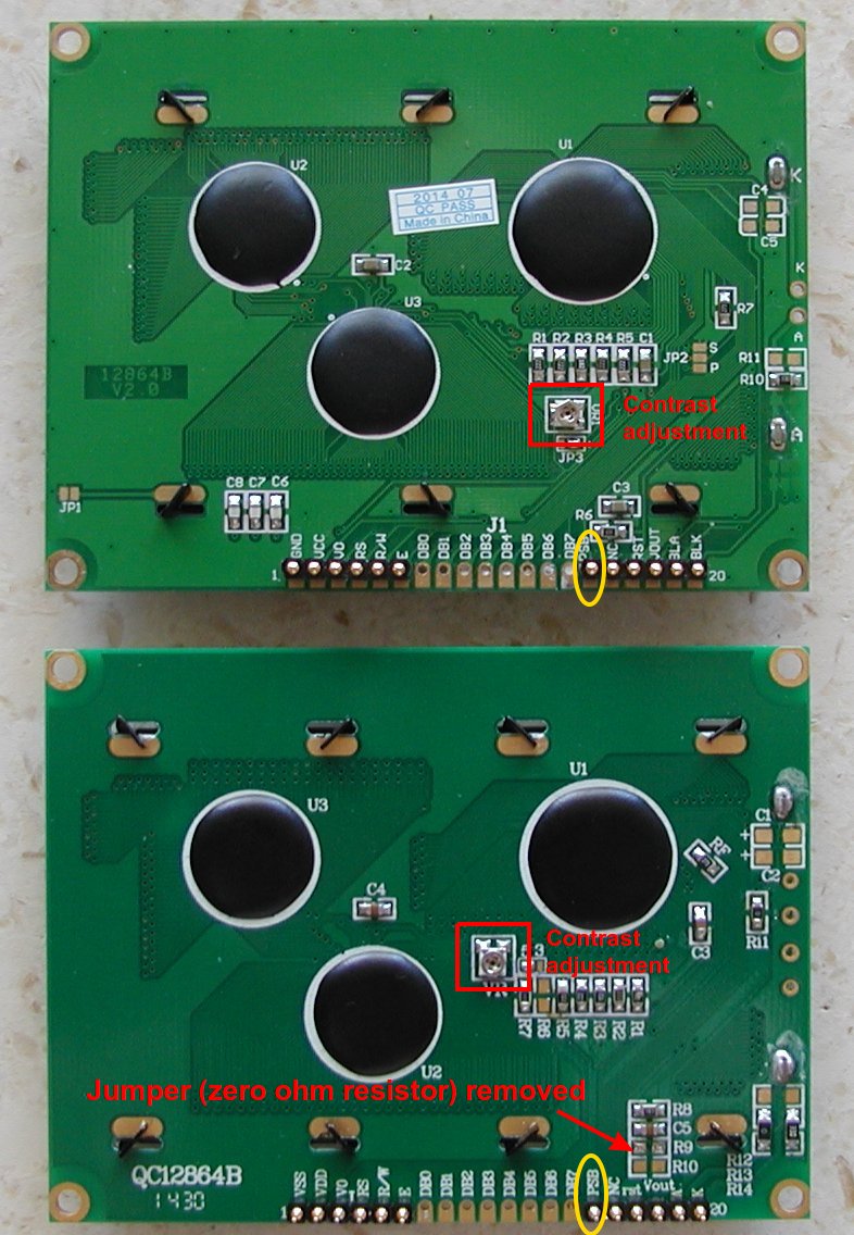
Apparently some of them do have a built-in contrast adjustment, but they'te not all the same https://i.imgur.com/KM9N0JM.jpg

 proven tusk
@north stream
got it to work
display temperature on the screen in a box
now i need to make a code with a 2 minute countdown and 20 second countdown and run those when a button is pressed
and what does the reset do? it is set to 8. Does it mean that if it detects an input in that pin, it resets?
north stream
I assume when it initially configures the display, it uses the reset pin to get it into a known state.
proven tusk
oh okay
 minor flax
Anyone know of some good libraries that will handle pushbuttons? Single click, double, triple... holds... I'm trying one now "OneButton" and it's not working very well on a Grand Central M4.
proven tusk
does anyone know a solution to this issue? when i put my finger on the three pins, it works but when i move it away, the lcd board glitches out
 sweet jay
So im coding an Arduino to light up LED in different sequence depending on where a pot is. I have two pots one is for choosing the sequence the other is for controlling the lights in the sequence. I am stuck on when controlling the lights on sequence 2 it use sequence 1 for the first 2 LED and then does sequence 2 for the rest. I was wondering if someone would be able to get in a called and I could screen share the code and work through it with them.
obtuse spruce
well - @sweet jay - let's start by you putting your code in a pastebin and I can take a look that way
sweet jay
thank you
obtuse spruce
give me a min. to digest it
sweet jay
ok sounds good
if you want to get in a voice chat so I can explain the problem I can do that
obtuse spruce
oops - give me another min... my 80 year old mother just called... be back in 5 min or so
sweet jay
do u want me to join
obtuse spruce
sure - I'm over in the Marie Curie voice room
 young hare
Hi, how do I make a dc motor go in either direction
It's the breadboard part I am confused with, I understand the code behind i
t
north stream
The usual approach is to use something called an "H bridge" which is capable of supplying power in two different directions.
young hare
Thanks I'll look into that
north stream
Here's one popular chip for that purpose: https://www.adafruit.com/product/807

Run four solenoids, two DC motors or one bi-polar or uni-polar stepper with up to 600mA per channel using the L293D. These are perhaps better known as "the drivers in our Adafruit ...
young hare
My kit comes with a shift register, is that what I need? It looks the same
It also inclues a relay
north stream
Alas, that's something else: it lets you convert serial to parallel (or vice versa, depending on which chip you have). They're often used to control several pins using just a couple.
You can wire a relay as a motor reversing switch.
young hare
Any pointers on how to do this? I'm quite new to it all and only have a programming background the circuit side is quite confusing
so far I have it so based on a button press it will rotate right, my tutor used two pins and set 1 to high and 1 to low but I'm unsure on what circuit he used
Does that sound like a relay?
north stream
That sounds like the pins were set up with boosters: the pins themselves can supply high and low voltages, but they can't provide enough current to operate a motor directly.
young hare
How would I go about doing this? So far I am using a resistor, transistor and diode. It is only a very small motor
north stream
That's sufficient to turn the motor on and off (and even vary its speed, if you use PWM), but not reverse it.
young hare
Ahh I see that's what I have currently
north stream
A manual reversing switch is wired like this: https://rollertrol.com/images/schematics/switches/DC-motor-reversing-switch-schematic-wiring-diagram-285x275.jpg
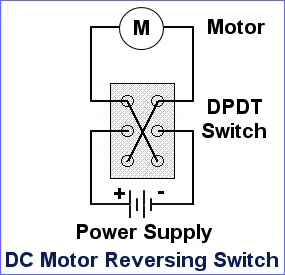

A relay is wired similarly, but is operated electrically instead of manually. However, a relay also needs a resistor, transistor, and diode to drive it (electrically, relays are similar to motors)
young hare
I don't really understand the graphics, what would I google to get a simple breadboard image of the wires connected?
north stream
The tricky part is the breadboard connections depend on the particular relay you happen to have.
Sometimes kits like that come with diagrams or URLs for more information.
north stream
Hmm, let me look that up
young hare
Thanks
167 (odd symbol) 2A 120VAC and 2A 30VDC if that helps
The kit I am using is the ARDX Arduino Experimentation kit
north stream
I scribbled down the basic layout. It could probably be clearer if it was neater and I used different colored pens, but hopefully you can see the basic arrangement
I left out the diodes, but they'd be hooked up like your existing one.
young hare
Cheers I'll give that a go
north stream
I'm guessing your professor's setup had one pin high and one low for one direction and swapped them for the other direction.
This one will work a little differently: one pin is motor on/off, and the other pin specifies direction (high is one way, low is the other)
young hare
That's fine he said we can make our own, I appreciate it
north stream
I guessed on the transistor pinout as well, but since you've already built a transistor driver, you already know how to wire those.
elder hare
can someone please help me looking over this pinout for this library compared to my ESP32 DOIT DEVKIT V1 pinout and see if there is any pins i need to change :/
library (in the image)
DOIT ESP32 DEVKIT V1 PINOUT
https://www.esploradores.com/wp-content/uploads/2019/05/ESP32-DOIT-DEVKIT-V1-Board-Pinout-30-GPIOs.jpg
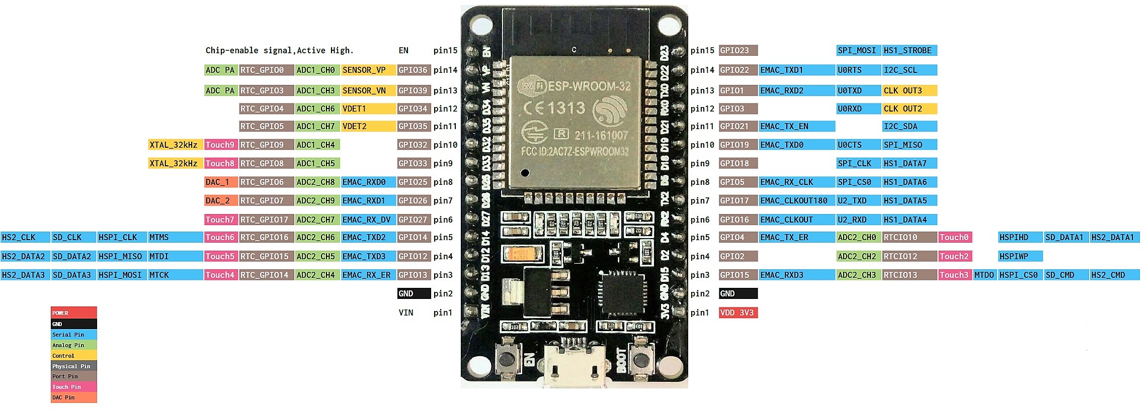
This is the result :/
north stream
Try hooking up all the grounds. Also make sure your software is configured for those pins and the right size panel and multiplexing. Some panels have an E line as well. Some I/O pins on the ESP32 are special and don't have full capabilities.
elder hare
@north stream so all the ground are now hookedup and nothing changed so i/we can rule that out!
the library is configured to Width = 32 and Height = 32
so that is correct
as i understand it the E line is only used when doing more then 1 panel in series
or rather the 64x64 and up are using E line
not the 32x32
 mystic gate
hi people, i have a problem, dunno if somene can help?, i'm trying to make a "Window" sensor, (Open / Close), i'm using MQTT and Hassio for that, the code to detect the window state works, but when i want to publish to mqtt, it crashes, someone know what is happening?
sorry but the code does not fit in one message.
void loop() {

  if (WiFi.status() != WL_CONNECTED) {
    delay(1);
    Serial.print("WIFI Disconnected. Attempting reconnection.");
    setup_wifi(true);
    return;
  }

  if (!client.connected()) {
    reconnect();
  }

  client.loop();

  ArduinoOTA.handle();

  int currentState = digitalRead(Detector);
  if(savedState != currentState){
    savedState = currentState;
    Serial.println(savedState); // this line excecutes, no problem
// HERE IT CRASHES
    client.publish(light_state_topic, (char*)savedState); // HERE IT CRASHES
  }
}
So, savedState is an integer, so when you cast it to a char*, that's converting it into a pointer and saying "publish whatever data is at this random numerical memory address". A crash in that situation is quite likely, as the address might not even be valid, or could contain anything.
I'm not quite sure what you want to do instead. Are you trying to convert it to an ASCII string to publish it?
mystic gate
well the metod require a constant char, or so it says when i try to compile with other kind of variable
that code never give me problem before, i did use it in a callback from the client and worked fine
void callback(char* topic, byte* payload, unsigned int length) {
  Serial.print("Message arrived [");
  Serial.print(topic);
  Serial.print("] ");

  char message[length + 1];
  for (int i = 0; i < length; i++) {
    message[i] = (char)payload[i];
  }
  message[length] = '\0';
  Serial.println(message);

  savedRelayState = atoi((char *)message);
  digitalWrite(Relay1, savedRelayState);

  client.publish(light_state_topic, message, true); //here is working

  digitalWrite(LED_BUILTIN, LOW);
  delay(100);
  digitalWrite(LED_BUILTIN, HIGH);
}
client.publish(light_state_topic, (char*)savedRelayState, true); // this works too
Yeah, so it sounds like publish() expects a character array, so you probably want something like:char message[10]; itoa(savedState, message, 10); client.publish(light_state_topic, message, true);
 vestal yacht
Hello, I'm using a feather M0 and I am trying to work out what clocks it uses. Is the clock they use an internal resonator? I can only see a 32k one on the board which is for the RTC right? So it's internal?
cedar mountain
Seems like it, yeah, there's an 8MHz internal RC oscillator which is good to about 1% accuracy.
north stream
I think the M0 chip has an internal clock multiplier too, it might derive its main clock from the 32kHz crystal
cedar mountain
Oh, good point. I hadn't seen that sort of PLL range before, but you're right... it can indeed multiply up from 32kHz. Neat!
obtuse spruce
I believe the Feather M0 boards have an external crystal with is used to derive the system clock. The crystal is 10ppm or 20ppm - so you get a much more accurate system clock (40MHz) than, say, the ItsyBitsy M0 which uses the on chip osc.
vestal yacht
But the only crystal I see is a 32k one, it must be derived from the internal 8M one? 1% seems quite good!
cedar mountain
What @north stream was saying above is that this M0 can actually multiply up a main system clock from the 32k crystal via a 1500x PLL, so that might be the source.
vestal yacht
Woah that blows my mind!
obtuse spruce
yes - that is what is happening in the M0: The external crystal is the reference - and it is clock multiplied up to get the system clock.
 proper forum
Will I damage the RFM95 if I attach it to 3.3v and use 5v logic?
cedar mountain
Quite possibly, yes. It doesn't seem to say anything about having 5V-tolerant pins.
vestal yacht
Thanks @obtuse spruce !
 strange torrent
anyone have any experience sending i2c between a nano and a Feather M4?
I didn't realize the nano had 5v logic and the feather 3.3v. I was wondering if there was a way to get them talking without buying additional special components
north stream
Not very special: a couple of MOSFETs is all that's required for an I2C level shifter.
strange torrent
okay, thanks
cedar mountain
There's also a decent chance that just running with pullups to 3.3V will work on both sides.
strange torrent
how would I set that up
I was looking at this:
I am going to get a logic-level converter, I didn't realize they were this cheap/simple to set up
thanks
proven tusk
The if statement in the void loop() is running yet the button hasn't been pressed down? can someone assist
cedar mountain
How is the button wired up?
You also want to remove the semicolon at the end of the if statement, as that terminates it prematurely.
proven tusk
Can anyone with knowledge on how to connect a 128x64 lcd screen to an arduino UNO and make it work with an LiquidCrystal library please help me. If you don't know how to do it please don't @ me. @ me if you can help. I am willing to pay money
north stream
As we found out previously, not all of those displays are the same: were you able to find out which version was yours and (better yet) get a data sheet for it?
dreamy minnow
hey, i tried wrinting my own wifi recoonnect funtion on the esp8266 but kinda failed
Pastebin
Pastebin.com is the number one paste tool since 2002. Pastebin is a website where you can store text online for a set period of time.
any tips?
dreamy minnow
nwm, it was useless
 strong perch
I bought one of the Tri-Color Gizmo boards but it refuses to display anything on the screen. I followed the instructions in the learning guide, but nothing (I tried it out with CircuitPython as well). The serial output is just this, with no errors displayed:
        Command: 0x1
        Data: 0x3, 0x0, 0x2B, 0x2B, 0x9,
        Command: 0x6
        Data: 0x17, 0x17, 0x17,
        Command: 0x4
        Data:
Waiting...OK!
        Command: 0x0
        Data: 0xCF,
        Command: 0x50
        Data: 0x37,
        Command: 0x30
        Data: 0x29,
        Command: 0x82
        Data: 0xA,
Waiting...OK!
        Command: 0x61
        Data: 0x98, 0x0, 0x98,
  Set RAM address
        Command: 0x10
        Command: 0x13
  Update
        Command: 0x12
Waiting...OK!```which sketch are you running?
strong perch
Ok, found this comment in the code (GizmoTest)
// for Gizmos rather than the Arduino version since there are additional SPI
// ports exposed.```I would have expected that crucial information to be very visible in the learning guide.
It works when I follow that advice.
leaden walrus
@strong perch added a new call out to the guide here:
https://learn.adafruit.com/adafruit-circuit-playground-tri-color-e-ink-gizmo/arduino-code
please take a look, can change / move / etc. if you have suggestions
strong perch
@leaden walrus Looks like the perfect location! Thanks!
leaden walrus
np. is it still not working with circuitpython?
 formal onyx
Hello, looking at an example sketch and I was just wondering what the & are for in this code:
at line 33.
 woven mica
Its a reference operator, it passes the address of the floats, not value
cedar mountain
That allows the function to reach back and modify those variables, versus just receiving the values to operate on.
 dull bison
anyone know how i can declare a color and use that color for more than one strip???
like Color red = (150,0,0)
cedar mountain
Yep, there are examples of that in the NeoPixel library:uint32_t magenta = strip.Color(255, 0, 255);
dull bison
@cedar mountain but now i can only use magenta with the strip led, what if i want to use it for a strip2 ledstrip???
cedar mountain
The uint32_t value isn't associated with a particular strip, so you can use it wherever. It's just using the strip API to construct the variable.
dull bison
ok so if i have 3 strips made like adafruit_neopixel strip1 till 3 i can just use them there with the strip command?
cedar mountain
Yeah, just pick one of them to construct your color with.
formal onyx
I'm having a lot of trouble trying to get my arduino to play an audio file from a microSD card. This is my code: https://pastebin.com/k2cu7eMk, I'm using an HW-125 micro-SD card board, and I just get "sd fail" every time. I'm using an arduino mega, and wired up according to this chart:
I tried formatting the SD card, it does have a file on it "what_is.wav" which is 8-bit mono
While searching online I found something about setting pin 10 or 53 to output, and then high, but I had no success with either pin.
And it is powered by 5v, which is another common issue people were having online.
north stream
You do need a select line so it knows you're talking to it (that's the SS column). 5V signals do need to be level shifted.
 wooden wagon
Hi, I’m new to arduino and was wondering if someone could explain what joystick.h does differently than keyboard.h, practically speaking
loud horizon
Never buy a nano that doesn't have ch340 or ch340g, its bricked
Choose the ones with the white button
proven tusk
is it possible to set up a 128x64 20 pin lcd screen to use LiquidCrystal lib?
cedar mountain
Depends on the particular screen. I don't think there's a standard 20-pin interface.
proven tusk
@cedar mountain @north stream would the connections for the image above be the same as the one below?
one is a 16 pin and the other is a 20 pin
 gleaming void
The issue I am having is that the sensor has a 4 second delay between new readings. I was wondering if there was a way to shorten this to like half a second.
Sensor I am using: https://www.amazon.com/gp/product/B0732VQ4Q2/ref=ppx_yo_dt_b_asin_title_o02_s00?ie=UTF8&psc=1
Code I am running
const int waveIn = 7;
const int led = 4;

void setup() {
  // put your setup code here, to run once:
  Serial.begin(115200);
  pinMode(waveIn, INPUT);
  pinMode(led, OUTPUT);
  digitalWrite(led, LOW);
}

void loop() {
  // put your main code here, to run repeatedly:
  int result = digitalRead(waveIn);
  if(result == 1){
    result = 0;
    digitalWrite(led, HIGH);
    Serial.println("Got it");
    digitalWrite(led, LOW);
  }
}
Its just a simple digitalRead on the pin and if its high it turns on an LED through a digitalWrite.
The LED turns on and stays on for 4 seconds so I know its because of the sensor still outputing 1. For the pin connections to the sensor, I am using the VIN to 5v =, OUT to my pin 7, and GND to GND.
cedar mountain
It looks like there are pads for a capacitor on the back side of the board, C-TM, which adjusts the detection timescale, but it can only go higher unless your board already has a cap on it to remove: "Adjust repeat trigger time, default trigger time is 2s; increasing capacitor's capacity will make repeat trigger time longer; and actual counting trigger time can operate as below: Stick capacitor on C-TM, test 9196 3-pin frequency F, repeat trigger time T=(1/f)*32768"
wooden wagon
Hi guys I am a student new to arduino and working on making a project for a math class. I want to use one of those 8x8 LED screens and plot 4 simple points, then apply matrix transformations to that point.
What’s the best way to start thinking how to do these? Can arduino do matrix operations in the code? Or will I have to convert things to bits and do the operations manually?
 sacred dagger
Hey guys. Can someone help me with the millis function? For example what is the equivalent of millis for delay(300)?
north stream
Something like ```arduino
unsigned long next;
void loop() {
unsigned long curtime;
curtime = millis();
if (curtime > next) {
// do something
next = curtime + 300;
}
}
Depends on the platform though
pine bramble
Good evening! I'm trying to make it so the potentiometer determines the point in which the servo motor moves in this picture.
#include <Servo.h>
// Servo library
const int potpin = A0;
int potValue = 0;
int servoAngle = 0;
Servo myServo; // creates an object called myServo of the Servo class
void setup(){
servoName.attach(9); // Telling which pin is connected to myServo

pinMode(myServo, OUTPUT);
}
void loop() {
 potpin = analogRead(A0); // constant potPin for the potentiometer pin

 myServo = map(0, 1023, 0, 179);

 servoName.write(angle);

 delay(100);
}
This is my current code and I just wanted to make sure it's coded properly for it's task.
north stream
I think instead of servoName.attach() you might want myServo.attach(). I'm guessing the Servo driver does the pinMode() call for you. In any case, pinMode() doesn't take a Servo instance as an argument, it takes a pin number.
pine bramble
Does that mean I have to change myServo in pinMode to 9? Or is it fine if I switch servoName.attach() to myServo.attach()?
north stream
I think you should do the second change and I'm guessing that Servo does the pin mode for you, so you can omit that line entirely.
pine bramble
For myServo = map(0, 1023, 0, 179); , could I replace it with myServo = map(potValue, 1023, servoAngle, 179); since the values are already established?
north stream
Ah, map() takes 5 arguments, and you want to put the value returned into potValue, not potpin
So more like ```arduino
potValue = analogRead(potpin);
angle = map(potValue, 0, 1023, 0, 179);
myServo.write(angle);
angle would represent "servoAngle", right?
 rich frost
I just upgraded from a Metro 328 to Metro M4 Express AirLift. I migrated my SHT10 temp/humidity sensor over, and i'm getting really high readings. there must be a conversion or baud rate, but i'm too green to figure it out! Please help!
north stream
Ah, I copied angle from your write() call, but your variable declaration doesn't match that, so you'd want to change one or the other so they match
pine bramble
Ok, thank you!!! Here is what I've got from what you've said
#include <Servo.h>
// Servo library
const int potpin = A0;
int potValue = 0;
int servoAngle = 0;
Servo myServo; // creates an object called myServo of the Servo class
void setup(){
myServo.attach(9); // Telling which pin is connected to myServo

pinMode(9, OUTPUT);
}
void loop() {
 potValue = analogRead(potpin); // constant potPin for the potentiometer pin

 servoAngle = map(potValue, 0, 1023, 0, 179);

 myServo.write(servoAngle);

 delay(100);
}
north stream
Looks reasonable, and you might still be able to omit the pinMode() line
pine bramble
Ok, thanks again!
north stream
You could add a pinMode() line to set potpin as an input, but it defaults to an input anyway, so it's not technically required.
 inner flame
Is there a way to use i2s microphone on Arduino uno
cedar mountain
The simple answer is probably "no", as that microcontroller doesn't have I2S support. There miiiiiight be some way to hack it through the SPI peripheral, but you're probably better off just picking a different board.
(Also, please don't spam multiple channels with the same question.)
inner flame
Ok
 desert wharf
I bought one of the 64*32 LED matrix boards . I use the 5V/2A power, and Arduino Mega to control it. It have been light up successfully, but the intensity of the LED isn't a constant, it will keep flashing when I (drawPixel). Please help me to let intensity become constant.
 green heath
I had a flickering issue with my lcd 16x2 because I had one too many clear screen and a timer interrupt interrupting.
I fixed it my only updating every 10 ms
Maybe something for you
 steep cobalt
Hello
I am a beginner on Arduino and want to make something so I have to use it.
I want to create 3 toggle buttons from already finished code.
I will be using the Arduino Pro Micro.
We will use 3 B10Ks and 3 buttons. Can you connect 6 devices to one VCC?
You need to fix your code. Please help

Throttle Quadrant with Reverse Thrust for Flight Simulator
Inspired on Cessna Caravan - One truly amazing aircraft!
This throttle quadrant uses three analog ports in an Arduino to handle throttle, propeller and cutoff/mixture. It is fully compatible with the new Microsoft Flig...
north stream
Yes, you can connect 6 devices to one Vcc, however, buttons are normally connected to ground.
steep cobalt
Could you put the values of the two toggle buttons in the code?
I don't know how to code, so it's very hard...
stuck coral
Could you rephrase what you are trying to do?
stuck coral
Do you have it wired together?
steep cobalt
The parts haven't come yet.
stuck coral
Ah, well Im not too familiar with this joystick library so maybe Im not the best to help, thought you wanted to connect buttons the usual way.
obtuse spruce
@steep cobalt - your problem is here:
  if (currentButtonState1 != lastButtonState1)
  {
  Joystick.setButton(1, currentButtonState1);
  lastButtonState1 = currentButtonState1;
  }
Or, really, here:
  int currentButtonState1 = A8;
  int lastButtonState1 = A8;
  int currentButtonState2 = A9;
  int lastButtonState2 = A9;
You are confusing a value that is the number of a pin, with the value of the pin.
stuck coral
Oh i see, I was confused reading it XD
obtuse spruce
Notice that you've added these to a section the defines variables that are "nice names" for the pins.
obtuse spruce
This code was missing something that would have made it clear. It should read:
const int throttle_pin = A1;
const int prop_pin = A3;
const int mixt_pin = A2;
Note that I added const - which tells the compiler - and reminds yourself - that these values are only nice names - not values you can change.
So what you wanted to add would be this:
const int button1_pin = A8;
const int button2_pin = A9;
oh
obtuse spruce
You need to get straight in your mind that in Arduino -- the pins are referenced by integers - they all have numbers -- and that number for the pin is distinct from the state of the pin.
steep cobalt
Yes, thank you very much!
obtuse spruce
So, the declared value button1_pin is just a number that refers to a particular pin --- that name itself isn't the value of that pin.
steep cobalt
  {
  Joystick.setButton(1, currentButtonState1);
  lastButtonState1 = currentButtonState1;
}```What should I do with this part?
obtuse spruce
you'll need to define a variable to hold the last button state, and a variable to hold the current state --- and you'll need to read the pin each time through the loop.
Like this:
int lastButtonState1 = -1;
int lastButtonState2 = -1;

void buttons() {
  int currentButtonState1 = digitalRead(button1_pin);
  if (currentButtonState1 != lastButtonState1)
  {
    Joystick.setButton(1, currentButtonState1);
    lastButtonState1 = currentButtonState1;
  }

  int currentButtonState2 = digitalRead(button2_pin);
  if (currentButtonState2 != lastButtonState2)
  {
    Joystick.setButton(2, currentButtonState2);
    lastButtonState2 = currentButtonState2;
  }
}
oops - fixed it.
steep cobalt
int lastButtonState1 = -1;
int lastButtonState2 = -1;

void buttons() {
  currentButtonState1 = digitalRead(button1_pin);
  if (currentButtonState1 != lastButtonState1)
  {
    Joystick.setButton(1, currentButtonState1);
    lastButtonState1 = currentButtonState1;
  }

  currentButtonState2 = digitalRead(button2_pin);
  if (currentButtonState2 != lastButtonState2)
  {
    Joystick.setButton(2, currentButtonState2);
    lastButtonState2 = currentButtonState2;
  }
}

void potentiometers() {
Is this part correct?
obtuse spruce
No - it needs to be outside of loop
obtuse spruce
No - look at potentiometers - see how it is defined on it's own outside loop, but called from loop
same thing here
the code I gave you defines a new function buttons that we'll use to keep the button code nice and tidy - just like potentiometers function keeps that code tidy.....
then you'll call both of those from loop - so each time through the loop each function is called once.
does that make sense?
steep cobalt
void loop() {
Can I write it after it is finished?
Can you send me the finished file? I think it will make sense
obtuse spruce
You had originally added code to loop - instead of adding the code I gave you to loop - you're going to add the code I gave you above after the whole loop function:
void loop() {
  ...
}

int lastB....
...

void buttons() {
 ....
}

void potentiometers() {
  ...
}
see the structure there - duplicate that
you'll need to get used to this construct of wrapping up bits of code in a function, outside of the loop function, but then calling it from the loop function
obtuse spruce
no
pay attention to the function and bracket structure in the code I showed above -
you can't put a function inside the brackets of another function
steep cobalt
void loop() {
void potentiometers() {
Is this part wrong?
obtuse spruce
yes
steep cobalt
oh!!
obtuse spruce
look the code you started with - before you added the buttons - and see how potentiometers as a function was defined - and then used
you're going to do the same with buttons
obtuse spruce
right that is where potentiometers was called
you're going to want to put a call to buttons in there as well
steep cobalt
void loop() {
potentiometers();
buttons();
}
obtuse spruce
good
steep cobalt
obtuse spruce
now see how potentiometers is later defined on it's own in the file - outside of the loop function? Again, you'll do the same with the buttons defintion above (besure to cut and paste the corrected version from above)
there ya go
try that
steep cobalt
Wow, thank you so much I'll try as soon as the parts arrive
I don’t know the code very well, but it’s really mysterious. Thank you
obtuse spruce
cool --- take some time to look at all the code bits we needed for each button.... getting the idea of state in your mind clear is going to help you as you continue with this stuff
steep cobalt
I understand so well, thank you so much
obtuse spruce
remember - the code (and the computer) are dumber than you think. Think of the code as written for a very dumb robot that is going to follow what you say very literally
good luck
steep cobalt
Thank you so much🙂
 raven perch
How do I use a Bluefruit LE UART with a seeeduino xiao in Arduino? I can't seem to find device-specific wiring/code.
stuck coral
Pins 6 and 7 on the xiao are market as UART so you just need to make a serial connection than other examples code should work just fine
CTS and RTS are not needed in this setup
raven perch
I connected to it with the Bluefruit Connect app, and on uploading the example controller sketch there are no errors, but nothing appears in my serial output when I press a button.
stuck coral
There are a lot of steps between setting up, and this, so you have it connected together?
raven perch
Yes, TX on the Bluefruit is connected to RX on the Seeeduino, and RX on the Bluefruit is connected to TX on the Seeeduino. 3v and GND are also connected.
stuck coral
Great, and the bluefruit connects with no issue? Can I see your code on the xiao?
brb
raven perch
stuck coral
Is there a way to just give me a pastebin?
raven perch
Sure, one sec
Pastebin
Pastebin.com is the number one paste tool since 2002. Pastebin is a website where you can store text online for a set period of time.
stuck coral
Looks like the issue is the fact you are using software serial quickly lookong at it while walking, that requires the cts rts lines and wastes cpu time
You want to use the hardware serial available to you through a SERCOM like other m0 boards
raven perch
<- Couldn't find Bluefruit, make sure it's in CoMmanD mode & check wiring?
In my serial console
stuck coral
That will happen if you use software serial and dont connect the other lines
They cant talk correctly right now
Try using hardware serial
stuck coral
Are you sure? Now that Im back to my desk it looks like you are using no active serial port
Unless the xiao has a implementation not present on other boards
raven perch
Pretty sure... what can I do to check?
stuck coral
The best way would be to use an oscilloscope, but here I think you are able to put the module in serial mode and just view the output
raven perch
What do you mean by 'view the output'?
stuck coral
View the serial output from the BLE module via the app
If you dont see anything, then the micro isnt sending anything to the BLE module
raven perch
I went into the IDE and re-uploaded the sketch with the app open and connected to the module. Nothing appeared in the console of the app, and the app disconnected from the module when the sketch finished uploading.
stuck coral
Thats odd... But if you put the module into UART mode, connect to it, view the output, then reset the microcontroller what happens?
raven perch
It sends ATZ 5 times, so it's getting data. It doesn't seem to be sending anything back, though, because I still get <- Couldn't find Bluefruit, make sure it's in CoMmanD mode & check wiring? in my console.
stuck coral
That means the micro is sending data to the module, which is why it disconnected earlier, but cannot receive data, sounds like software serial to me. So if you put the module back into command mode, same thing happens? Clearly the library is doing much more handholding with serial than I thought, I dont like it
Let me peek at their implementation one sec
raven perch
In CMD mode with the console open, when I reset the microcontroller, it disconnects.
stuck coral
Okay, but same serial output from your micro correct?
raven perch
Yes
stuck coral
Awesome, so we just need to resolve the receiveing of data.
stuck coral
Change the mode setting in your config from 12 to -1 if you dont have it connected to start. But I am currently looking at the Xiao serial config
raven perch
Where is the mode setting?
raven perch
Oh, the mode pin is already -1.
raven perch
I didn't change anything, I don't think. That's weird.
stuck coral
Seems to me between your paste and now something changed, I can only work on one sketch at a time 😜
Did you need to add a boards file for your board?
The xiao has terrible documentation with a lot of fluff and not a lot of helpful info
raven perch
What's a boards file?
stuck coral
Ah there we go, because it makes sense to have 4 pages that is the same set of docs
raven perch
I noticed that about the docs, it's annoying
stuck coral
Could you try adding #undef SOFTWARE_SERIAL_AVAILABLE on line 18?
Oh i see, nevermind, i mean let me know how that goes but I am finding this implementation confusing
Could I see your wiring to make sure nothing stands out there?
stuck coral
Thats fine
Alright, I see the code that is returning false, it looks like you are in fact using hardware serial, and I dont see an issue from here, could i see the back of the xiao
raven perch
stuck coral
Hm, you've just about stumped me, I cannot tell why you cant receive data, we could try making a serial bridge
raven perch
What's that?
stuck coral
It would bridge the USB serial and hardware serial so you can interact with the BLE module with the serial monitor yourself and see whats going on exactly.
raven perch
How would I do that?
stuck coral
Something like this, I have not tested nor compiled
void setup() {
  Serial.begin(9600);
  Serial1.begin(9600);
}

void loop() {
  if (Serial.available() > 0) {
    Serial1.print(Serial.read(););
  }
  if (Serial1.available() > 0) {
    Serial.print(Serial1.read(););
  }
}
remove the ; after the Serial1.read() --- subexpressions don't end in semicolons
But... that won't do what you want because print is not the companion to read
void loop() {
  while (Serial.available()) Serial1.write(Serial.read());
  while (Serial1.available()) Serial.write(Serial1.read());
}
try that
stuck coral
My bad I origonally had a int variable and I quickly copied and pasted to go take care of chores, you are right
Not sure why youd use while vs if though
obtuse spruce
either will work... but if there is a whole line of info in one direction or the other - it just does it all at once.
stuck coral
But you dont handle both at the same time 😉
obtuse spruce
yup - depends on what you need
stuck coral
True
obtuse spruce
if one end is spewing constantly then the if is better....
though the loop is likely to execute faster than the UART transfers bytes
raven perch
The serial output is blank
stuck coral
Hm, so the receive line isnt getting anything at all
Was hoping youd get a malformed response
@obtuse spruce any ideas looking at our previous messages? They are using hardware serial, the RX/TX connections seem correct, Ive been looking through the library and the variant code and cannot find a good reason for this
Sending data to the BLE module works, receiving does not
raven perch
What if I try software serial?
stuck coral
Then you will need to connect CTS and RTS but right now the RX line just isnt working period unless someone at SEEED totally screwed the pooch
I assume they at least tested their serial implementation
stuck coral
@raven perch do you have a multimeter by any chance?
raven perch
I have two
stuck coral
Okay, we could also test if the hardware serial implementation is working correctly for this board, would you rather try that first?
This is where mzeros while is handy-
#include <SoftwareSerial.h>

SoftwareSerial mySerial (RX, TX);

void setup() {
  Serial.begin(9600);
  mySerial.begin(9600);
}

void loop() {
  if (Serial.available()) mySerial.write(Serial.read());
  while (mySerial.available()) Serial.write(mySerial.read());
}
This will make sure that the issue isnt from seeed, so then we know the Arduino implementaion is good, the library is good, the application is good, then in my mind only the hardware would remain
Oh, we also didnt try sending commands, I never told you to do that, do you still have the hardware serial bridge uploaded?
north stream
If you have the while, you don't really need the if too
Oops, they're different interfaces
stuck coral
Yeah, was hoping to give software serial the best chance possible 😉
Since everything returned will have a newline at the end
 digital stone
Can someone help me? When I try to verify my code it states,
"C:\Users\drago\Documents\Arduino\ProjectComponent2\ProjectComponent2.ino:7:32: warning: ISO C++ forbids converting a string constant to 'char*' [-Wwrite-strings]
Password Spy = Password( "700" );
^
C:\Users\drago\Documents\Arduino\ProjectComponent2\ProjectComponent2.ino:8:36: warning: ISO C++ forbids converting a string constant to 'char*' [-Wwrite-strings]
Password Analyst = Password( "316" );
^
C:\Users\drago\Documents\Arduino\ProjectComponent2\ProjectComponent2.ino:9:37: warning: ISO C++ forbids converting a string constant to 'char*' [-Wwrite-strings]
Password Director = Password( "279" );
^
C:\Users\drago\AppData\Local\Temp\ccb9O9Mw.ltrans0.ltrans.o: In function main': C:\Program Files\WindowsApps\ArduinoLLC.ArduinoIDE_1.8.42.0_x86__mdqgnx93n4wtt\hardware\arduino\avr\cores\arduino/main.cpp:46: undefined reference to loop'
collect2.exe: error: ld returned 1 exit status
exit status 1
Error compiling for board Arduino Mega or Mega 2560."
stuck coral
What library are you getting the password object out of?
stuck coral
heresy
It looks to me like you are supposed to use string objects.....
There can be multiple constructors, Im not sure why its like this
Hold on, let me clone that library
digital stone
ok 👍
stuck coral
I dont see a password object
And i read the compiler error backwards
Where are you getting Passwords.h?
stuck coral
Could you find that for me?
stuck coral
In documents, or in a folder in documents?
digital stone
A folder in documents
stuck coral
Could I have its path?
digital stone
Documents -> Arduino -> Libraries -> Password -> Password.h
stuck coral
That library looks pretty old, where did you get that?
Last modified November 16, 2013, at 03:14 PM
I mean, if it works then thats fine, but Im not sure its what you need here
I dont see how its related to AutoConnect
digital stone
Yea I researching a libraries to use for passwords and this one appeared. I cant remember where I exactly found it... prob would have been useful to remember
stuck coral
What do you need to do with passwords?
digital stone
The password works with the keypad. If the correct 3 passwords are entered, servo converts 90 dergrees.
stuck coral
What hardware are you using? ESP32 or ESP8266?
If ESP8266 you have a Hash.h library you can use
Not sure about the ESP32 but I see mentions of it
You could use that
Then it will also use the hardware hashing peripheral so it will be nice and fast
digital stone
Just to make sure, how can I figure my hardware? I want to say ESP8266 but I just want to confirm.
stuck coral
It says on the metal top
Then you dont even have your codes in the code/binary, to break the code youd need to brute force SHA1 which is possible but way above basic tampering
Or SHA256 I think if ESP32, which is... much less possible if you add a nonce
digital stone
ESP8266
stuck coral
Cool, you for sure can import Hash.h
Do you need help with implementing?
And this is easier because we dont need to worry about strings
digital stone
No for right now. If I do run into a problem I can tell you.
stuck coral
Okay 👍
elder hare
hmmm i get "Brownout detected" when using one of my USB cables... is the cable broken/damaged? :S
when i changed to a new one i bought i dont get that brownout message :S
stuck coral
Yeah, happends sometimes, or if youre using front panel desktop USB that can also be an issue
elder hare
im connecting from the USB on my Corsair key board
but as stated when i connect with my new USB cable everything is fine :S
stuck coral
Yeah, happens, can also get cables with bad datalines. Most of my bad cables are from amazon
 nova comet
if im currently using an arduino uno for my project, assuming im using all the pins, would this https://store.arduino.cc/usa/nano-33-ble be a viable replacement? What do i have to consider?
A low-power bluetooth 5.0 board designed for demanding power savvy projects.
stuck coral
There are many platforms to choose from for wifi microcontrollers, I like the nRF52840 which that board has, the thing to watch out for is the IO voltage
On the UNO its 5V while on this and most other microcontrollers, its 3.3V
nova comet
Yeah i noticed that as well. im going to make a PCB for my chessboard project. I wanted to integrate the mcu directly into the board, reccomendations?
stuck coral
Its a good choice, in fact earlier, for this project, I think I recommended a Adafruit nRF52840 board
What type of motor are you using?
Oh wait thats right
nova comet
no motor
stuck coral
Should work the same
nova comet
just piece recognition
stuck coral
I remember your project clearly now
Do you want batteries?
If so, I recommend the Adafruit feather has the JST for the battery and charging circuit
nova comet
You know what
The board already has a usb c port on the side. So if i have a battery, ill be keeping the usb b breakout on my pcb regardless.
Scratch that^
No battery
I do want to keep my usbc breakout though
stuck coral
Ah, okay, then it doesnt matter which nRF52840 board
I would adapt that USB-C to whatever USB is on the board you choose
loud horizon
Hello, I purchased a 7 segment SH5161AB Led and I was wondering how I might connect it to an arduino nano. Does anyone have a basic wiring to the nano for it?
I cannot use a breadboard, so soldering is mandatory

Recently I posted a turorial on Controlling 7 Segment displays with Arduino.
This video is a continuation. I will show you how we can control multiple 7 segment displays with just 3 pins of Arduino using 74HC595 shift registers.
The components used:
- Shift registor - https:/...
Would this video help, since I'm using it for a shift display on simhub?
nova comet
@stuck coral does this look right? One of my first times working with KiCad
the RGB terminals are for an LED, the two 8x1 terminals are for the rows/columns of the reed matrix, and the button terminals are for my two terminal button in the board
stuck coral
Is the MCP not a part built into kicad?
It looks correct beside the grounds not being connected, and your 5V connections are wrong
The nano is 3.3V logic so you need the button and MCP using 3.3V
nova comet
@stuck coral i decided to use an MCP23008 in the end, but i plan on putting a socket for the mcp. Which grounds do you mean? And you mean that all the pins currently connected to 5v should be on 3.3V?
stuck coral
Yes, and you see how there are two grounds from the nano? And you should use the MCP23008 symbol in kicad, that way your schematic is easier to read, you can just use a socket instead when you assemble the board
That way someone reading it can see the pinout
stuck coral
Looks like it, not sure why you added no connects everywhere
nova comet
for clarity i guess? I just removed some of the junctions that shouldnt have been there. At A0, A1, A2, A4, A5
stuck coral
Lol, no, thats wrong
Remove all the no connects, and remove the junctions you dont want
If there is no junction, then the lines are not connected
Its makes it less clear
stuck coral
Looks good! Normally we also add symbols for our ground and voltage rails, but this will work just the same
stuck coral
Correct
nova comet
I should add the vcc symbol to my voltage rail?
stuck coral
That or +3.3V label
stuck coral
Looks better than the first schematic I made
nova comet
ive never really worked with KiCAD before, but I have experience in circuit design through some of my university classes, so this wasnt a huge learning curve
 pulsar junco
what about sda/scl pullups?
stuck coral
Oh thats a great tip
nova comet
my sensors and instrumentation class really beats me over the head
stuck coral
I love kicad, I just got a kicad winter hat today
nova comet
Pullups for the SDA and SCL?
pulsar junco
also might be worth considering using two MCP23008s
stuck coral
4.7K for both
pulsar junco
yeah pullups to VCC
stuck coral
also might be worth considering using two MCP23008s
I disagree
pulsar junco
I was just thinking that the code would be more symmetrical that way but that's not that important
stuck coral
Thats just more CPU time left on the table
nova comet
i was originally using a MCP23017 but it broke and this was all they had in stock, but it works great
I dont think my current circuit has pullups on those two pins.
stuck coral
The dev board you are using does (probably)
nova comet
the uno?
stuck coral
Yeah, I think the UNO includes them let me check
Might be wrong, but with i2c you need pull up resistors
If not then an internal pullup was used which isnt great
pulsar junco
what's wrong with an internal pullup?
stuck coral
Too weak for the I2C spec, should be between 1 and 10K, internal resistors are almost always more
Then you just break spec
pulsar junco
ah too weak of a bus current?
stuck coral
Its probably using internal pull ups, I recommend putting them on the board
If its on the board, you have the option for both solutions
stuck coral
Ohh so this specific AVR has a TWI specific pull up on the I2C pins, I would still include them as best practice. Also, I thought you were using the nRF52, did you change your mind?
stuck coral
Its labelled as a nano, did you use the right symbol @nova comet?
nova comet
I was planning to use the nano ble
stuck coral
Ah, got it, so not a feather correct?
nova comet
i wasnt able to find a symbol for this specific nano so i just used the regular nano. But i plan on using this
A low-power bluetooth 5.0 board designed for demanding power savvy projects.
nova comet
I don't plan on adding a battery so i just thought i'd leave it
stuck coral
Nevermind
I read the specsheet, I just helped someone with this, I know its a nrf52 my bad
Good choice
stuck coral
Not that Im seeing right away, I can sit down in a sec. The nrf52 has a IMU, you could do cool things like tap to wake or something
I know you have the button, but could do something with it
nova comet
honestly this project is mostly finished for me. I just wanted to build the PCB for self learning.
stuck coral
Ah, very nice, 10 PCBs for $5 at PCBWay
I highly recommend, they go above and beyond what I expect them to do
Just got a big order for work from their assembly service, 1% had very minor issues none were DOA
nova comet
awesome:)
let me know if you have a chance to sit down and take a look. I did this from memory because i dont have the board with me right now.
I also removed the voltage divider and bt module since the nano has ble
pulsar junco
join the motley crew in #help-with-hw-design if you want!
nova comet
i only ask iotpanic because he knows my project well
 slate gazelle
So I'm just plugging in a M0 Feather I got recently and it seems to be just boot looping
stuck coral
@nova comet looks good
nova comet
:)
stuck coral
@slate gazelle what makes you think that?
slate gazelle
figured it out. it doesnt like my hub
its blink pattern made me think it was boot cycling, but it seems to be normal
stuck coral
Yes, they come with a blink sketch on them
slate gazelle
it was blinking all 4 leds in a pattern. i had assumed the red light by usb was power which made me think it was cycling, but i loaded up blink and its the one that blinks
hmm. its been awhile since ive tried messing with arduino ide. but this m0 now just wants to blink its life away. uploading just never completes
slate gazelle
interessting. going thru the tut it refuses to upload the wifi firmware check or firmware updater example, but can upload scan networks
 young flint
i'm trying to use the circuit playground accel_mouse example but i get an error:
fatal error: HID.h: No such file or directory
25 | #include "HID.h"
i think i narrowed it down to the mouse library, and the hid library not being included in some versions of the ide? i'm on arduino 1.8.13
i was googling around and found some stack overflow questions with similar issues, and tried installing a new hid.h but still no luck
wooden wagon
hi guys i accidentally ordered the mega 2560 kit instead of an uno kit. is it still going to work?
woven mica
hi guys i accidentally ordered the mega 2560 kit instead of an uno kit. is it still going to work?
yes
wooden wagon
I started doing some of the projects in the kits and I’m a bit confused about why the code seems to do the same but in different ways... for example, if I have a LED on pin 3 why does it say #define LED 3 but also int LED = 3
They seem to do the same thing
stuck coral
Id have to look at it but sounds like you are correct
vivid rock
@wooden wagon these two are not quite the same, but in many cases you can use either of them
#define LED 3 is instructing the arduino ide to replace in the sketch everywhere LED. by 3
int LED =3 defines an integer variable with initial value 3
wooden wagon
I’m also a bit confused about the idea of defining these pins in the first place. Instead of saying “pin 3 is called LED” then say “make LED high”, why not just say “make 3 high”
vivid rock
the difference between these two is that if you use int LED = 3, you can later in your program change the value of this variable to something else
stuck coral
Normally with pin definitions that wont change, #define is used
vivid rock
as to why you need to define it at all..
wooden wagon
Ah that makes sense. Otherwise you would have to back and change every instance
vivid rock
two reasons: first, it makes code more readable
second , if you later decide to connect led to pin 4, you would only need to changeone line, rather than try to find all places where you set led high or low
wooden wagon
That makes sense. Thx
 stuck trout
Does anyone know why ESP32s don't support the Analogue Write command when using the Arduino environment?
stuck coral
ESPs have their own way of using PWM, let me grab you a link

Learn how to generate PWM signals with the ESP32 using Arduino IDE. Build a simple circuit that dims an LED using the LED PWM controller of the ESP32.
pine bramble
Hi, So it's my first time Using MQTT, i wanna know How can i compare the string e.g livingroomOn or livingroomOff, to the payload? this is the example sketch from pubsublibrary and in this code they are using the first character to turn on or off and led but i want to compare to a string like if (payload == "LivingroomOn") Turn on the led.
Can you tell me what changes do i have to make in this sketch?
cedar mountain
You're probably looking for the strcmp() function.
north stream
So connecting a pot to ground or ... ground? I'm not sure what you're really trying to accomplish there, but I think there's at least one error in the drawing
pine bramble
You're probably looking for the
strcmp()function.
@cedar mountain Umm no that will not work in my case cause there are multiple buttons sending strings for example one button for "livingroomOn" and "livingroomOff", and the other button for "bedroomOn" and "bedroomOff"
i want to do this
steep cobalt
How should I fix it?
north stream
The way to compare strings is strcmp() as Ed suggested: I see no reason it would not work in your case.
pine bramble
else if (payload == "bedroomOn"){led2 turn on}
else if (payload == "livingroomOff"){turn off the led0}
``` AND SO onif (strcmp(payload, "livingroomOn") == 0) {
// turn on LED 0
} else if (strcmp(payload, "bedroomOn") == 0) {
Two-pole toggle switches can be used to switch between two inputs, or can be used with pull-ups like single-pole switches
woven mica
@steep cobalt but what are you trying to do
steep cobalt
I am curious if it is correct to connect a 2 pole toggle switch like this
north stream
Like what?
steep cobalt
I think it is a translation mistake because I am not good at English.
obtuse spruce
@steep cobalt - you need to tell us what you want the toggle to do - the drawing you gave is certainly wrong: The toggle switch wired like that does nothing useful.
steep cobalt
Is there any problem if I connect it like this with the one I made code yesterday?
obtuse spruce
Also - what are the two boxes above the toggle? more toggle switches?
steep cobalt
That's right. I have three toggle switches.
I will just connect to the game and use it.
obtuse spruce
The circles on the right are potentiometers?
steep cobalt
Oh, right!
obtuse spruce
and you want to read them as on or off? okay -
steep cobalt
yes
obtuse spruce
connect one side to VCC, one side to GND, and the middle to an inputs ---
which I see you now have (why did i read it as both sides GND...??? hmmm... my bad)
obtuse spruce
mind you, you don't need toggles for this kind of switch -- normally you'd just use a simple switch, connect on side to GND, the other to the input pin... and then program the pin to be "pulled up" --- so that it reads HIGH when the switch is open, and LOW when it is closed.
pine bramble
@north stream
obtuse spruce
Note - you will read the potentiometers with analogRead(A1) and same for A2 and A3. You'll read the switches with digitalRead(6) and same for 8 and 9.
north stream
Looks like your payload isn't a character string type.
obtuse spruce
note that the pin names are different if you are reading analog vs. digital
steep cobalt
I want the other to the input pin... and then program the pin to be "pulled up" --- so that it reads HIGH when the switch is open, and LOW when it is closed.
pine bramble
Looks like your payload isn't a character string type.
@north stream its byte, i sent you the screenshot of it
obtuse spruce
@pine bramble - you are missing a close paren. on the if
steep cobalt
So we need to fix this?
  const int prop_pin = A3;
  const int mixt_pin = A2;
  const int button1_pin = A8;
  const int button2_pin = A9;
const int button3_pin = A7;```@pine bramble - you are missing a close paren. on the
if
@obtuse spruce Yup
obtuse spruce
@steep cobalt
  const int button1_pin = 6;
  const int button2_pin = 8;
  const int button3_pin = 9;
Notice on the diagram of the board there are two sets of names for these pins - the A names are for use with analog functions, the bare numbers for use with digital.
obtuse spruce
Now, it turns out that either will work with either function
pine bramble
steep cobalt
I want the other to the input pin... and then program the pin to be "pulled up" --- so that it reads HIGH when the switch is open, and LOW when it is closed.
obtuse spruce
BUT - it keeps things consistent and clear if you refer to analog pins with the "analog" names, and the digital with the numbers.
pine bramble
Do you have anyother way to compare payload to the string?
steep cobalt
What should I do?
north stream
The problem is the payload isn't a string, it's a byte array: you'll need to convert/adjust it before you can compare it to a string
steep cobalt
I want the "pulled up" --- so that it reads HIGH when the switch is open, and LOW when it is closed.
obtuse spruce
pinMode(button1_pin, INPUT_PULLUP)
steep cobalt
Oh, where should I put it?
obtuse spruce
@pine bramble strcmp(static_cast<const char*>(payload), "xxxyyy") == 0
@steep cobalt - in setup() - it only needs to run once
steep cobalt
  pinMode(button1_pin, INPUT_PULLUP)
  pinMode(button2_pin, INPUT_PULLUP)
pinMode(button3_pin, INPUT_PULLUP)```@pine bramble you can do this, if you like:
const char *msg = static_cast<const char*>(payload);
if (strcpy(msg, "doThis") == 0) { .... }
else if (strcpy(msg, "doThat") == 0) { ... }
@steep cobalt - look at how statements are formatted in C++ -- look at the rest of the code... you'll see those are missing semicolons;
pine bramble
@pine bramble you can do this, if you like:
const char *msg = static_cast<const char*>(payload);
if (strcpy(msg, "doThis") == 0) { .... }
else if (strcpy(msg, "doThat") == 0) { ... }
@obtuse spruce Yeah that will be better a way, let me try it
steep cobalt
i have to fix it elsewhere too?
obtuse spruce
@steep cobalt - I don't know what you mean - but ... each statement in C++ is terminated by a ; -- and those are three statements - three things you want setup() to do.
steep cobalt
  pinMode(button1_pin, INPUT_PULLUP)
  pinMode(button2_pin, INPUT_PULLUP)
  pinMode(button3_pin, INPUT_PULLUP)

  //Initialize Joystick Library
  Joystick.begin();

  // Initializes serial port.
  //Serial.begin(9600);
  // Waits for serial port to connect (needed for Leonardo only).
  //while (!Serial);

  // Joystick Axes Setup

   // Throttle
   Joystick.setThrottleRange(thr_min, thr_max);
   // Prop
   Joystick.setRxAxisRange(prop_min, prop_max);
   // Mixture/Cutoff
   Joystick.setRyAxisRange(mixt_min, mixt_max);

}```Oh is this right?
obtuse spruce
You're missing semicolons (;), @steep cobalt -- look at how each line of coe is formatted (ignore the comment lines, of course)
steep cobalt
  pinMode(button1_pin, INPUT_PULLUP);
  pinMode(button2_pin, INPUT_PULLUP);
pinMode(button3_pin, INPUT_PULLUP);```good - try compiling that
steep cobalt
Oh, my God
pine bramble
@obtuse spruce is it strcpy or strcmp?
steep cobalt
So the switch connection is vcc,gnd,digital signal?
obtuse spruce
@pine bramble -- my bad -- strcmp
@steep cobalt - NOOOOOO that would short GND and VCC in the upper position,
which would be bad
top - no connection, middle - digital input pin, bottom - GND --- that should work
steep cobalt
Oh, my God. We don't need vcc.
obtuse spruce
you will be toggling the connection of the digital input pin between GND (where the pin will read LOW) and no connection (which will cause the internal pull up to have the pin read HIGH)
pine bramble
Ummmmmmm.. @obtuse spruce
obtuse spruce
yes
steep cobalt
It'll work out, right?
My parts will probably be here in three days. I'm really looking forward to it.
Thank you very much.
obtuse spruce
@pine bramble --- I'm poking at my IDE
pine bramble
alright
obtuse spruce
@pine bramble --- the unsigned / signed conversion means we need to use reinterpret_cast -- not static_cast
that should work
pine bramble
So ... what changes do we have to make?
north stream
Would a plain cast msg = (const char *) payload work?
pine bramble
obtuse spruce
@pine bramble - check your parenthesis matching
obtuse spruce
As for casting:
const char *msg = (const char *)payload;                    // [1]
const char *msg = static_cast<const char *>(payload);       // [2]
const char *msg = reinterpret_cast<const char *>(payload):  // [3]
1 is plain-ol'-C style casting. It'll let you do bad things with no warning at all
2 & 3 are new C++ style casting: more verbose, but you make it clear just how much craziness you are expecting
2 means roughly - change this so long as it doesn't have wierd corner cases
3 means roughly - I know the bits in memory are right - just treat as this kind of thing.
3 is not uncommon for use with things like payload -- the transport doesn't care what it transports, you just get a bunch'o'bytes. You need to "know" that these are a string, or an array of floating point numbers, or whatever... Here, you "know" it will be a string.
The nice thing about C++ style is that the compiler will tell you if the cast would require more craziness than you expected.
pine bramble
Very Very good explanation thanks
ok so the //[1] and //[3] worked without any errors but im still not getting any response from the led
north stream
It's possible the message has some whitespace attached to it, causing it not to match
 marsh charm
Hello, I'm looking for a cheap source of ESP32s and some assorted sensors (plus any recommendations). I mainly want Hall Effect sensors, temp/humidity, and gas/particulate sensors.
obtuse spruce
@pine bramble ... What function is producing this payload? I'm thinking it is not a plain string like you think... (a clue: that we had to cast it)
 safe shell
@marsh charm relatively inexpensive chips and modules are readily available, but if you're looking for more ready-to-go dev-board-like experience, the least expensive esp32 I've found is the m5stack Atom Lite (limited I/O, but <$6)
marsh charm
Awesome thanks! Any idea about sensors?
safe shell
not other than the usual suspects...  et al
et al
 oblique spruce
Anyone know if it's possible to modify the wifi behavior on an arduino mkr wifi 1010? It doesn't look like the WiFiNiNA library reference page has anything that's going to let me modify power or band choice, but I wasn't sure if there's a way to poke deeper inside it. (I've got some folks who're having wifi difficulty in an area where the 2.4G coverage is a bit mediocre)
north stream
If all else fails, I suppose you could look at the source code. It's also possible that NiNA supports it and the library doesn't expose that functionality.
safe shell
esp32 only supports 2.4, but there are esp idf calls (accessible within Arduino IDE) that allow you to change channel, etc
oblique spruce
Ah, okay. I don't know if that'll help, but it might.
I've got a class of students messing about with the mkr's but living in a dorm area with mediocre 2.4G connectivity. Since they're beginners, there are limits to what we can push them to do as far as "OKAY AND THEN WE HAND-EDIT THE FIRMWARE" kind of solutions. 🙂 But something that can be done within the IDE has promise.
safe shell
lol I feel you
I'm not expert, have just done a few basics this way, but API is here: https://docs.espressif.com/projects/esp-idf/en/latest/esp32/api-reference/network/esp_wifi.html and with the right includes, IDF functions are generally accessible (e.g., https://medium.com/home-wireless/how-to-program-an-esp32-in-arduino-while-using-esp-idf-functions-90033d860f75) and more examples with some web searching
with 2.4GHz spotty, I'm really not sure if / how much further fine-tuning will take you
 gaunt glacier
void loop() {

  io.run();

  if (stepper.distanceToGo() != 0) {
    stepper.run();
  }
  else
    stepperOff();
}
As is, it runs extremly slow. if i change the if to a while, its as fast as it should be, but, causes my esp8266 to crash since it blocks the loop. How do i do this?
oblique spruce
Thanks, @safe shell! I'll run that by some folks.
dreamy minnow
is there a way to use big numbers?
like, strings do me well, untill some point
where i need to use ints
well, longs, or floats
and if i convert for example 59000111 from string to float
it pops 59000112
gaunt glacier
okay the problem is io.run() its slowing down my loop
dreamy minnow
and multypling that with another float that is 100, pops out 59000100,2
gaunt glacier
how do i throttle it?
north stream
Like, slow it down more?
vivid rock
One option is, instead of running io.run() in every ieration of the loop,do it once every 50 ms
Or whatever is the maximal interval necessary for normal operation of wifi
dreamy minnow
any reason why this doesnot work?
pasiStep = (procStep / 100) * pasiMaxFloat;
ignore the name, they are all ints, just haven;t moddified yet
well, longs
cause int/int is zero
i'll see myself out
obtuse spruce
@dreamy minnow - float only had about 6 decimal digits of precision --- which is why you are seeing those value changes.
double will give you about 15 digits
but remember that both formats are approximations - not exact, especially when it comes to large integers.
double is expensive in time on all MCUs.... float is only fast on some. Another option, if all you need are integers, is long long - which is 64 bits - so about 10^18 max.... they are not bad in expense... but not direct in hardware.
 shy jetty
Hey all! I'm making a usb splitter, I bought a mechanical switch, this one to be exact, and then the MTS-403 version.
I've made a nice box with female male jackets, and made some cables to connect them to multiple pc's.
I've made this because I have a keyboard and a mouse I use for my homeserver, and my personal computer, and was tired of having to switch the usb cables around every time. First I only wanted the keyboard to be split, but when I ordered the switch I realised I might want my mouse as well. So, now. The question is; can I connect 2 usb's in some manner, so that I only have to wire up one of those MTS-403's?
I was thinking something like this, with the 4 switches in the middle representing the MTS-403 switch, but I'm not sure if it would be safe, and good for the computers health if I connected 2 usb 5v's to the same usb.
obtuse spruce
connect the mouse and keyboard to a small USB hub --- then just switch the hub between the two computers
shy jetty
Thing is, I'm trying to make my own usb hub
obtuse spruce
er - that isn't hub - but a switch...
shy jetty
I've 3d printed a nice box, and cant really fit a hub in there as well
obtuse spruce
normal hubs don't do what you are trying to do
well-- you really can't connect the 5V from two different USB hosts together
obtuse spruce
You mean - in a single computer that has multiple USB ports - how is 5V connected? They could do it any number of ways.... BUT - in all cases they are driving the 5V line. If you connect two different hosts together - they are each trying to drive the 5V line.... this isn't a good situation... and could damange one of the hosts.
stuck coral
This breaks the USB spec in more ways I can count 😆
obtuse spruce
You can use a very small tiny non-powered hub for this. Like https://www.adafruit.com/product/2998

Do you want your cup to runneth over with USB ports? Do you want it to also be filled with the sweet, sweet nectar of an on-off switch? If the answer to either of those questions is yes - or ...
plug that into your swtich box - and the switch box to the two computers
shy jetty
I'm just wondering, what is going on in that usb hub then exactly? I have some spare female ports laying around, and enough cable. Could I try to replicate whats going on inside there then?
stuck coral
The USB hub is its own device, there is a active IC and it talks to the computer, and relays info depending on the types of links downstream
I just read the USB spec, highly recommend, its a good read and this will all make sense
Being a hub is a very involved process, there is a lot going on inside