#help-with-arduino
1 messages · Page 80 of 1
 vivid rock
 dark shard
And also because I want to learn to understand these things so if I get the sensor to do everything I won't learn as much. 🙂
vivid rock
for learning, I learned a lot about sensor fusion from work of Kris Winer: https://github.com/kriswiner
(when I coded the madgwick filter for my project, I based it on his code) - check it out, it may be useful to you. I am not familiar with the Paul Mcormic series.
Anyway, back to the datasheets. Give me couple of minutes
dark shard
Of course and thank you again. 🙂
vivid rock
OK, here comes.
Strangely enough, Adafruit library doesn't support changing accelerometer range, so indeed you will have to do it yourself.
According to datasheet, you would need to write to register ACC_Config an 8-bit word containing various settings: last two bits for range, previous 3 bits for bandwidth, etc.
I am not sure what bandwidth you want, but assume for a second that you want 31.25 Hz bandwidth, normal operation mode, 8G range. Then you would need to write to ACC_Config word
00001010b
which is same as 0x0a in hex
dark shard
Oh the b at the end isn't a bit which makes sense because it is not a 0 or 1. derp thank you.
vivid rock
b is just indication that it is binary 🙂
dark shard
and that would be using the Wire.write that I mentioned before?
vivid rock
next you need to find what is the register address of ACC_Config; it is somewhere deep in datasheet, you can find it
dark shard
I have that I think just a sec.
vivid rock
for writing, it is easiest just to copy the code for function write8 from adafruit library:
bool Adafruit_BNO055::write8(adafruit_bno055_reg_t reg, byte value) {
  _wire->beginTransmission(_address);
  _wire->write((uint8_t)reg);
  _wire->write((uint8_t)value);
  _wire->endTransmission();

  /* ToDo: Check for error! */
  return true;
}
replacing _wire by Wire
_address shoudl be BNO055 i2c address
vivid rock
let me know if it works
dark shard
okay and ACC_Config is 0x08 so I would do the bool adafruit write8 as you put with:
Wire.beginTransmission(0x28);
Wire.write((uint8_t)0x08);
Wire.write((uint8_t)mybinary);
Wire.endTransmission();
cool, I will try that, thank you.
vivid rock
Minor suggestion: instead of just writing Wire.write(0x08); do
#define ACC_CONFIG_REG 0x08 //acceleration config register address
Wire.write(ACC_CONFIG_REG);
same result, but makes code so much more readable
but you probably know it already - sorry for repeating the obvious
dark shard
I did not, I am that new to this so thanks for the suggestion!
vivid rock
normally anything like that which is taken from datasheet is defined in the beginning of your script (or in a separate .h file) using #define, and then in the code you always use the defined constants (traditionally, all uppercase) instead of binary values
dark shard
Okay, so that way you're reading what it is and know where in the datasheet to look for it?
vivid rock
it makes it much easier to understand what is going on.
e.g. (in another library, with another sensor)
mpu.setGyroRange(MPU6050_RANGE_500_DEG);
is much easier to understand than if they had put there binary value
dark shard
so far example if I put #define NORMAL_BAND_RANGE 00001110b and then put NORMAL_BAND_RANGE into the Wire.write() it'll take the 00001110b as if it were a uint8_t ?
since that was what it wanted before?
vivid rock
yes
dark shard
Hmm it is giving me back a "was not declared in this scope though I put the define directly above it, I tried moving it out of the class too.
DERP it was a typo lol onto the next error.
@vivid rock getting so close on it. Now it says multiple definition Adafruit_BNO055::write8 etc. with unsigned char after the reg_t
We're getting there! 😄
vivid rock
of course, you shoudl change the function name - you can't have two functions with same name. E.g.
#define ACC_CONFIG_REG 0x08
#define BNO055_ADDRESS 0x28

void  configure_accel(byte config_data) {
  Wire.beginTransmission(BNO055_ADDRESS);
  Wire.write(ACC_CONFIG_REG);
  Wire.write(config_data);
  Wire.endTransmission();
}
// now, we can call it:
uint8_t accel_config=00001010b;
configure_accel(accel_config);
Hmmm, so to confirm, we are writing a class that wants an argument that is a byte and will be passed where it says config_data in the class. We then define our byte and call the class with the byte as our argument.
I'm getting "expected constructor, destructor, or type conversion before '(' token. I'm looking for other examples of that error.
vivid rock
we are not writing a class - just a function
did you use Adafruit_BNO055::?
this indeed shoudl only be used when defining a class
so remove it and everything should work now
vivid rock
you are welcome
dark shard
Next step is to get the void Adafruit_BNO055::setMode working 😄
So I can set it to AMG mode.
vivid rock
there is always the next step
dark shard
Once I get past this configuration stuff it'll be the matrix stuff and I'm a lot more familiar with that!
I GOT IT TO WORK!
Okay I'm able to move onto the matrix stuff. Thank you again. I appreciate it a lot.
 unborn pumice
bruh why doesnt my led turn on when i press the button
supposed to turn the white one on when i press the pushbutton
 north stream
The resistor is hooked up wrong and will cause a short circuit
 carmine jetty
quick question/maybe not so quick question. I got this breakout board :https://www.adafruit.com/product/4201
I am going to use it for wifi usage and eventually code in c# for a small test web app to collect data wirelessly. Are these useable for the arduino nano or would a more external power source be recommended?

Give your plain ol' microcontroller project a lift with the Adafruit AirLift - a breakout board that lets you use the powerful ESP32 as a WiFi co-processor. You probably have your ...
north stream
Perhaps, it can draw up to 250mA. The Nano's onboard regulator probably can't supply that much, but it can presumably forward power (via the Vin pin) from the Nano's supply
carmine jetty
interesting. I didn't know it could do that from the Vin pin. ill have to look at that. Other than that I should probably get/make my own battery pack for it
 mortal ferry
Has anyone ever gotten an SSD1306 or SSD1251 to work on an STM32 board/STM32F405 feather using Adafruit's libraries or a fork of such?
carmine jetty
I actually have one and got it working on an arduino nano, but I don't have an STM32 Board.
Sadly though I burned my screen out unplugging the ground first one time. >_>
I believe it can be hooked up to 5v
and you should follow this. b1 for SDA and 0b1 for SCL, or you can use B7 for SDA and b6 for SDA, or B9 for SDA and b8 for SCL
mortal ferry
I've got one of the SPI SSD1351 screens I'm trying to get working with a Feather F405... I can't find anything in the library itself that seems like it would be breaking it. The only architecture specific setting is the speed of the SPI line, and an F405 should be able to cruise through any of the speeds listed there
but I don't really know how STM32duino works with a library like this under the hood very well
It's especially frustrating that even software SPI doesn't work
north stream
Software SPI is fairly straightforward, I'm surprised it doesn't work.
mortal ferry
Yeah I was puzzled by that. I'm going to try getting it going on a Feather M4 and compare the two signals over SPI
on my saleae
I've found stm32duino can be a bit hit and miss
north stream
Ah, the Saleae should be useful for showing what's actually going on.
 odd fjord
@mortal ferry Are you specifically looking for arduino support -- the ssd1306 works on my feather_stm32f405 under CircuitPython.
mortal ferry
@odd fjord Yeah I'm working on a modification of UncannyEyes - so the SSD1306 works with just the basic libraries, on stm32duino?
oh no I missed that you said Circuitpython. Yeah I have no issues with any screen or device there and it's much easier for me to track what they are since I wrote all that code anyway haha
but not fast enough for UncannyEyes
if I can't get it going with Arduino I'm going to have to just do it in the HAL
odd fjord
Sorry, I have not tried Arduino with the stm32f405 at all ...yet.
 blissful meadow
I need help with a reister
My muiyi meter says 5
k
will that light up a led
one says 1k
wait nvm
 pulsar junco
do you know what color the LED is?
pulsar junco
200k is too high, do you know about ohms law?
pulsar junco
200 should be OK
unborn pumice
what does this even mean
i didnt even change the code xd
this exact code works on a different tinker cad board literally doesnt make sense
north stream
Error is on line 50 and you don't show line 50. I'm guessing an extra space got in.
unborn pumice
maybe but it randomly works now
do you know how to do an interrupt btw i cant get mine to do anything
north stream
Interrupts are a little tricky
unborn pumice
i literally just want the white led to turn on when i press the button
but it dont work
like i attach the interrupt and make it run when it changes , so when i press it
but it does nothing, is my button not connected or sumn
north stream
Hmm, you still have a wiring problem on your board, and interrupts are the hard way to do that
unborn pumice
yeah but i need to use interrupts for the thing im tryna do just testig it
whats wrong with the board?
north stream
The resistor is short circuited by the ground trace, so has no effect, which means there is no current limiting to protect your I/O pins or LEDs.
unborn pumice
its just a simulation though surely it doesnt matter
ok ill remove the resistor then
but that shouldnt affect the interrupt thing
i dont get why it does nothing though
north stream
The switch pin doesn't have a pullup resistor. Try changing the pin mode for the switch to INPUT_PULLUP
unborn pumice
nah doesnt work still
i just changed board to this
the reason i want an interrupt is so i can count how many times they press the button at the same time an led was pressed dow
led was turned on *
north stream
I think the first argument to attachInterrupt is wrong, but I'm not sure
unborn pumice
what else would it be
north stream
Ah, pin 2 is interrupt 0, so that should be okay, I was wrong (I usually do it differently)
unborn pumice
so interrupts just dont work on tinkercad maybe?
north stream
I don't know, I've never used Tinkercad. I'd probably test out the switch and LED wiring separately first to make sure they work, then add interrupts.
unborn pumice
yeah ill check my button acc can turn it on directly you mean
pulsar junco
https://www.youtube.com/watch?v=PIX6TZxukyo may be of some use.

This video explains how to use external interrupts with the EICRA and EIMSK registers to monitor a button press on an Arduino's digital input pin. It is part of a larger series of videos showing how to program an Arduino in Tinkercad Circuits. This content is taught in MAE 378...
I suspect the delays may be causing issues as well?
unborn pumice
possibly yeah
but like when it runs the interrupt the white light should just stay on
north stream
That's what I'd expect. For mysterious problems, my usual approach is "divide and conquer". So I'd find a way to make sure the switch works and the LED works, then worry about interrupts.
pulsar junco
I think the button should be wired across the bridge in the breadboard, no?
or wait
nevermind
 sweet sleet
should i get rid of the makefile when uploading to pic?
make[2]: *** [nbproject/Makefile-default.mk:110: build/default/production/main.p1] Error 1
sweet sleet
i got it fixed using the hex
can someone explain how i can use software serial
#include <SoftwareSerial.h>
SoftwareSerial s(13,12);
s.begin(9600);
then i can s.write, right?
and where do i plug in to use that tx? gpio13?
north stream
First argument is the RX pin, second argument is the TX pin. Note that GPIO13 has an LED on it, which can change the voltages somewhat (but is useful as an indicator that something is happening)
 tribal jewel
Also, are you using interrupts?
@north stream I contacted Infineon's technical team and they mentioned it is the multiplexer and crosstalk issue probably. I still haven't figured out what the issue is though.
 vast pagoda
hey! i'm trying to learn python with arduino but as a super noob I have some problems running code from thonny . Is there a proper way to configure thonny? I've already installed pyfirmata but python code seems not to work on arduino .. (im using this tutorial : https://realpython.com/arduino-python/ )

In this step-by-step tutorial, you'll discover how to use Arduino with Python to develop your own electronic projects. You'll learn how to set up circuits and write applications with the Firmata protocol. You'll control Arduino inputs and outputs and integrate the board with h...
north stream
@tribal jewel Thinking on it further, I'm also wondering what sort of pull-up resistors you're using on each sensor
tribal jewel
@north stream I contacted Infineon's technical team and they mentioned it is the multiplexer and crosstalk issue probably. I still haven't figured out what the issue is though.
@tribal jewel 10k on sda scl pins for the 2 sensors.
north stream
That should be low enough impedance to avoid crosstalk, so I suspect the problem is something else. I would probably debug it by adding logging to the driver so I can see what is going on that's causing it to hang.
tribal jewel
That should be low enough impedance to avoid crosstalk, so I suspect the problem is something else. I would probably debug it by adding logging to the driver so I can see what is going on that's causing it to hang.
@north stream Sorry my knowledge is very limited. Could you please direct me on how I can add logging to the driver?
@north stream Sorry my knowledge is very limited. Could you please direct me on how I can add logging to the driver?
@tribal jewel any tutorial could follow?
north stream
Not right now, I'm in a meeting
tribal jewel
oh my apologies. Whenever you are free. Thanks a bunch.
north stream
@tribal jewel What library are you using?
 hearty niche
I have been reading https://learn.adafruit.com/how-to-choose-a-microcontroller/32-bit-boards and got confused over the sentence »The Metro M0 gives you the power of a SAMD21G with the breadboard-friendly footprint of the Uno.« I don’t really see how the Uno is breadboard-friendly. It doesn’t seem to even fit on a breadboard. Can anyone explain?

Adafruit Learning System
A gentle guide for choosing a controller for your project
 obtuse spruce
I think they mean that it has female headers and is easy to jumper into your breadboard.
The Feathers can sit on your breadboard with male pin headers... but they eat up a lot of bread board space if all you need is a few GPIO lines.
vivid rock
Agreed, Uno is not particularly breadboard friendly
 wraith current
@vast pagoda it's a pretty vague problem. I would recommend learning python on a different system rather than combining it with Arduino from the start. I think it will just make it much more complicated to learn python when you have to deal with debugging the Arduino side combined with learning the language.
north stream
There is a Trinket M0 that fits nicely on a breadboard and doesn't take up much room, but only has a few I/O lines. The ItsyBitsy is a little larger, and has more I/O.
 hard pumice
What's up with this error message here?
obtuse spruce
Wellll... TOIE1 wasn't defined anywhere.... which then seemed to cause a cavaclade of other issues. I'd fixt that first.
Also, depending what what include files you are using (directly or indirectly), if math.h is included, then gamma is already defined:
extern double gamma (double);
because it is extern the compiler is expecting to see a defintion -- but then it is "surprised" when your definition of gamma is an array, not a function.
@hard pumice - hope that helps
 proven mauve
so... when it comes to libraries. I need to edit a single library file for a specific sketch, but only that one project needs the modification. What's the best way to handle that?
proven mauve
yes
tribal jewel
@tribal jewel What library are you using?
@north stream Wire.h and SoftwareSerial.h
proven mauve
I wouldn't mind switching to something more.... robust. But I use a lot of non-standard boards and so I'm worried I'll end up causing more troubleshooting problems for myself if I change to a nicer IDE
wraith current
Well if the libraries are just single files, then you could just copy them into your sketch directory and include them via quotes like #include "Wire.h" not sure if they have other dependencies that might break if you do that though.
proven mauve
kk, ty
vast pagoda
@wraith current thanks for your response. I tried to push it that way because i'd like to learn new things by doing projects that I can really commit myself to. But as you said maybe this time is better to just follow the paved path of tutorials and split those in two separate learning cycles.
wraith current
@vast pagoda I agree. get comfortable in both sides, then join them when you have a nice grasp of how things are working.
north stream
@tribal jewel Ah okay, so your code is talking to the sensors directly, and you're getting errors back from the Wire library? I'd probably just add Serial.println() statements before and after the calls to the Wire routines telling what they're doing and then watch the serial monitor to see which one is causing problems.
 ruby heart
Hey guys, just started an Arduino Nano Pomodoro project.
All was going well when until rearranging some of the wires so I can get most of my LEDS to pulse. I'm using mainly delays to determine the length of work and break sessions in the Pomodoro method (I know, not the best solution)
but all of a sudden, the Nano started speeding through the delays like it was on crack. It seems the clock that determines delay length has been sped up. I have a button input that i have set to high, i think some how I have changed the internal clock maybe. I've looked around of course but cant find a solution, maybe there's something I'm missing? I can post the code on request.
Doe's anyone have any ideas? thanks in advance
tribal jewel
@tribal jewel Ah okay, so your code is talking to the sensors directly, and you're getting errors back from the Wire library? I'd probably just add
Serial.println()statements before and after the calls to the Wire routines telling what they're doing and then watch the serial monitor to see which one is causing problems.
@north stream thanks. I will have a look and let you know.
north stream
@ruby heart I think the delay clock is one of the on-board timers, so if you've used some other functionality (PWM, servo, etc.) that uses one of the timers, it could have an effect on delay() behavior.
ruby heart
@north stream PWM yeah thats right, all the LEDs are on PWM pins to make them pulse, it was working fine though until I switched the wires around.
not sure what i changed but it must be something to do with that
north stream
I don't know offhand how switching wires around could have that effect, but that doesn't mean it can't happen!
ruby heart
Right? 😄 . When i started the project, I had the switch connected to d12 and adding a wire to it without being connected to anything returned a positive signal, turns out it picks up interference like an antenna. that baffled me for hours, so It seems anything is possible at this point 😄
 pine bramble
So I was trying to programm a serial.read with different actions. Heres my code:
int Read;
void setup(){
Serial.begin(9600);
}
void loop(){
if (Serial.available()){
Read = Serial.read();
Serial.write(Read);
if (Read == 1){
Serial.write("Ok");
}
}
}
And when I send a "1" to the teensy I get a 1 in the monitor but no Ok.
Anyone a idea what im doing wrong?
north stream
You presumably sent the ASCII character "1", but test is looking for a byte value of 0x01. Perhaps try Read == '1' to test for the 1 character instead of the 1 value.
pine bramble
Ok I found out whats wrong I need to put if (Read == 49) if im looking for a 1 lol but thanks anyway
north stream
That will work too: the value of a 1 character is 0x31 (hex) or 49 (decimal). I'll often use the '1' notation to make it clearer what I'm checking for.
To the computer, they're all equivalent, so it boils down to personal preference how you express it.
pine bramble
Yea '1' worked for me in the past but for some reason when I tried it out I didn't work either
north stream
Note that '1' is a character value and "1" is a string, which is two different things.
pine bramble
I used '' not ""
north stream
It seems to me that should have worked, I'm not sure why it didn't.
 nocturne prairie
Hello, I was using Pyfirmata to run my arduino Uno (because Im really too lazy to try to do it regularly) and ran into a problem with digital input. In my while true loop it will work for about 2-5 min then the digital input will only read True and will never read False(when the button is pressed). Does anyone know why or how to fix this?
north stream
Do you have a pull-up configured?
nocturne prairie
No I do not
north stream
That might have something to do with it: a pull-up resistor gives a "default" reading for a switch that isn't actuated, but I don't know a lot about your set-up so I'm just guessing here.
nocturne prairie
thanks
mortal ferry
Does anyone happen to know where core-identifying macros like ARDUINO_ARCH_NRF52 and ARDUINO_ARCH_SAMD come from? I'm trying to figure out if there is an equivalent for STM32 but I'm not sure where to look
north stream
I'm guessing boards.txt, but presumably the Arduino IDE unpacks those values somehow and hands them off via -D arguments to the compiler calls. If so, you can probably see it in build window if you turn on verbose output
 lunar cedar
I have an existing device that has toggle switches. I'm not entirely sure how they are wired, but I would like to "piggyback" off the existing toggle switches to have my arduino do some things when they are toggled. In other words, I want my arduino to safely be wired into these existing toggle switches without interfering with their current functionality and I was wondering if anyone had some advice on how something like this might be done.
vivid rock
@mortal ferry looks like it is in the file platform.txt as a complier flag. e.g. for adafruit nrf52, in the Arduino config directory (under Windows, it is typically <username>\AppData\Local\Arduino15) I have file packages\adafruit\hardware\nrf52\0.20.5\platform.txt which has this line
build.flags.nrf= -DSOFTDEVICE_PRESENT -DARDUINO_NRF52_ADAFRUIT -DNRF52_SERIES -DLFS_NAME_MAX=64 ...
so it defines among others macro ARDUINO_NRF52_ADAFRUIT
north stream
@lunar cedar You'll probably need to find out how the toggle switches are used. For example, if they were in a car and grounded something that was connected to +12V, you could build a circuit to divide and limit the voltage to safely let an Arduino monitor it (the voltage limiting is required in cars, due to occasional high voltage spikes). In other situations, different adaptations might be required.
 rose yarrow
what can cause an error compiling for an uno?
lunar cedar
@north stream OK. So what I do know is that the device (which is a Hasbro Ghostbusters Spengler Wand, in case that helps at all, haha) I'm trying to monitor runs off of 4.5V (typically 3 AA batteries). I currently have it hooked up to a LiPo battery in my Proton Pack which contains my Arduino Nano. The Nano is using INPUT_PULLUP mode on four pins to detect the state on 3 toggle switches and a momentary button on my normal wand, and since the Spengler wand has an identical toggle switch/momentary button configuration I'd love to be able to hook it in to my nano the exact same way, I am just worried because the Hasbro wand seems to be very picky about its Voltage (I got weird behavior when hooking it up to 5V as a test) so I've dropped all my votages down to 4.5V using a buck converter and my nano seems to be doing fine (it runs off the same power source).
- Will my voltage coming out of my pins when HIGH be 5V even though the power source supplying them is 4.5V?
- I have no idea how to isolate the circuit board on the Hasbro wand (or even if I need to) from my Arduino nano somehow, is there some diode configuration that would be relatively simple to set up?
Sorry if this is a lot of information and I know I'm asking for a lot, but I'm still learning in the area of electronics and my google searches have been pretty fuitless, haha.
@rose yarrow What error are you getting?
north stream
Ah, that's cool! I'm building an Arduino based proton pack of my own. It could be that if you get the Arduino and existing circuitry to agree on a ground reference, that you could read the values directly.
lunar cedar
Oh awesome, what a cool coincidence! Yeah, that's kind of what I'm hoping to do 😄 I do have it all hooked up on a common ground, as my ground is coming in on my power connection from my proton pack is the same ground that goes into my nano. So I want thinking I could just kind of solder some new wires onto the same points that the Hasbro wand uses to monitor its toggle switches etc but I'm worried about frying something.
rose yarrow
@lunar cedar error compiling to uno
 woven mica
@rose yarrow but what error
lunar cedar
Usually there will be some output in the text box at the bottom of the IDE:
If you can copy/paste that here then it will help people know how to fix your error.
rose yarrow
north stream
TeeEm, it seems to me like it would be safe (a 4.5V level is a valid logic "hi" level as an Arduino input), but it pays to be sure
rose yarrow
this is my code
http://prntscr.com/v42xb5
im wanting to use the angle from the gps logger shield to turn if it is over 180

 cedar mountain
It looks like it doesn't like including both Adafruit_GPS.h and NMEA_data.h. You might try removing the latter.
rose yarrow
i removed NMEA_data.h and it let me upload it
pine bramble
Hello
I need help with Arduino ,I'm noob .If you are eager to help me ,please dm me,thanks ❤️
 gilded swift
@pine bramble can you be more specific
pine bramble
I am waiting for the components to come ,but I struggling Understanding how to programm lcd screen for Arduino Uno
@gilded swift
gilded swift
Oh gotcha, have you written any code yet? And what lcd screen are you using?
pine bramble
Can I use tingercad as I am gonna have em in a week? No I haven't
gilded swift
Have you looked at this tutorial on the Arduino website?
https://www.arduino.cc/en/Tutorial/LibraryExamples/HelloWorld
Open-source electronic prototyping platform enabling users to create interactive electronic objects.
pine bramble
16x2 if I am not wrong
gilded swift
Okay, yeah that tutorial should be super relevant then
pine bramble
Thanks but I already so and I didn't get it :( feeling idiot
pine bramble
I don't know how to do the connection
I saw a tutorial on yt , wait minute please

You guys can help me out over at Patreon, and that will keep this high quality content coming:
https://www.patreon.com/PaulMcWhorter
This is a tutorial series for absolute beginners. We show complete newbies how to get an arduino up and running, and in this lesson you will w...
but for example why is it 13?
I'm trying to understand the concept,because I got the elements and the idea
gilded swift
13 is the pin for the on board LED
For Arduino and a lot of Arduino compatible boards, it’s become the standard LEDBUILTIN pin.
I’m not sure of the initial thought behind using pin 13, but it’s stuck ever since
pine bramble
got it thank you.Can I ask something more?
gilded swift
Definitely
pine bramble

How to Set Up and Program an LCD on the Arduino
In this video, I briefly show you how to connect a 16x2 LCD to an Arduino. After that, I go in-depth into which functions are available in the LiquidCrystal library to program it, and show you what they look like on the LCD. I a...
Why is it (16,2) for example?
And the Arduino-whiteboard has like cables inside for connect stuff?
gilded swift
16 characters wide, two lines
pine bramble
oh...Sily me 😂
gilded swift
Not sure of all the cables, but likely jumper cables to wire up projects
pine bramble
and this board contains the letters? or?
gilded swift
The LCDs are capable of displaying any letters you send to it from your program
pine bramble
So ,I will try using tingercad
And I will let you know for anything ,Is this ok with you?
Just to get to know Arduino
ok then thank you anyway ☺️
gilded swift
You’re welcome 😃
 silver stirrup
@heady sparrow Could you please review the PR on Adafruit_LvGL_Glue, because the ver 2 libraries it depends on are no longer available to install in the Arduino IDE Library manager. . The PR supposedly fixed it so it works with the current V3 library. I can’t figure out how to get LvGL_Glue working., otherwise.
 wispy hornet
hey guys so i have product 4201
and it shows how to connect it to the arduino uno
but i need help connecting it to the arduino mega
apparently i dont have the real arduino mega
here's an image of my pinout

Robu.in | Indian Online Store | RC Hobby | Robotics
Get The best combo of Arduino Mega board with Programming Cable and acrylic case at India's best Online Shopping Store Robu.in | Buy NOW for more offer & Coupon
north stream
It's an SPI peripheral, so normally would be hooked up to the SPI pins. Oddly, the Arduino illustration above doesn't show that (the SPI pins on an Arduino are GPIOs 11, 12, and 13). The SPI pins on a Mega (https://www.arduino.cc/en/Reference/SPI) are 51 (MOSI), 50 (MISO), and 52 (SCK). The default SPI select pin on a Mega is pin 53, but you can use pretty much any pin.
It also requires the BUSY and !RESET control pins to be hooked up, they can generally go to any available GPIO pins, then configure the software to match.
Your board matches the usual Mega pinout (the page you linked states "SPI: 50 (MISO), 51 (MOSI), 52 (SCK), 53 (SS).")
 grand basin
Can I save an array of values (a value for each of 12 MIDI CCs controlled by potentiometers) into one EEPROM address, or do I need a separate address per each CC Value? In other words, can one address store 12 cc pot values, or do I need one address per pot?
 stuck coral
@grand basin each address is a byte location in a pool of memory like on the arduino or in your computer, what bit size is the value you want to store? If eight bits, then you would in memory populate from 0xn to 0xn+C with n being where you're starting your write. If they are 16 bit values, each value will take two bytes in memory. If your value was only four bits long, you could store two valus in one byte of the EEPROM
wispy hornet
alright, thank you madbodger!
grand basin
@stuck coral I want to store midi cc values which is up to 127. that is one bit correct? one bit x 12 per address?
stuck coral
@grand basin No, that is either a unsigned 4 bit value, or a signed 8 bit value
Each "address" (byte) is 8 bits
Dont think of it as key:value, think of it as just a giant array
grand basin
okay. so having 12(pots) x 8 bits means storing 96 bits to a single address?
stuck coral
No, you would write 12 bytes, which starts at a single address but is contained within 12 address locations.
Each LSB of a address is one byte, when you tell the memory you want to store a value at 0x100, you're telling the memory to go to the 256th byte in the array of data, and then start writing 12 bytes
If you wanted to get the 12th byte, it would be at 0x10B
grand basin
I see. Happy I asked. I have a lot to learn.
stuck coral
For sure, its a fun process though 😉
grand basin
What would you suggest if I wanted to wrap my mind around the general rules of how this works? Like what can I learn to build a framework in my mind that makes sense of this? Does that make sense? I'm new so putting these things into words is like a different language ha.
stuck coral
Hm, I do know what you mean, embedded work is tough because it's computer science meets electrical engineering. Its turtles all the way down, and as a stack its complex, but each turtle is itself a simple concept. The framework you are looking for is how the turts fit together 🐢
I would first learn what is a computer, how does it work? In that venture you will get the answer of what is memory, and how do we represent and mutate it
Then you can think of the chip as simply a blob of memory, then you can learn how that memory is accessed later. It isnt important you understand the turtle below or above the flash chip, as long as you understand the interface between the turtles and you can learn about the rest later
grand basin
This is perfect, exactly the sort of answer I was looking for haha
stuck coral
Examples of what is below the blob of memory that is your EEPROM is SPI, and example of a higher level turtle would be a filesystem. And glad I was able to help. I recommend ben's breadboard computer project, he made a bunch of amazing low level videos about how a basic computer works

YouTube
Subscribe to see tutorial-style videos about electronics, computer architecture, networking, and various other technical subjects. If you want to see more on...
His whole channel should be a huge help
grand basin
Oh great, thank you! I've seen some other projects of his. If I report back with a question it will be with a deeper grasp on this 😄
stuck coral
Sounds good, looking forward to any future interactions
 short mica
How do I make a timer in arduino that will set off a buzzer at a specific time, that can be reset by an ultrasonic sensor. I can do this once, but my timer counts the entire time the program has been running and won't reset.
stuck coral
Are you using a hardware or software timer?
short mica
software
stuck coral
Could I see your implementation?
short mica
my code? sorry i have 0 background for this stuff
stuck coral
Correct, please use pastebin if sending a lot of code
Add a tone(11,0); when you reset the time value
Also, how long will this be running?
short mica
Probably a couple of hours and the values I currently have in myc ode are just so I can test it on a reasonable scale
stuck coral
Got it, but let me know if adding that tone function call works, its needed following line 42
short mica
Yea doesn't seem to work. The sensor seems to just make the noise from the buzzer base boosted
stuck coral
Hm, looking at the code my change was cludgy but should still work
short mica
I think the issues maybe comes from it not resetting properly? I almost sounds like it's being turned off then turned back on over and over again because the timer isn't actually resetting
stuck coral
Well if you put it after line 42, you reset the timer on that line
So it would turn off right when you reset the timer and only when you reset the timer
short mica
It definitely does not stop making noise
short mica
yes
stuck coral
Give me a min, almost done I am re organizing the code for readability
Oh lol, I see the issue, should have seen it earlier, one sec
Try this https://pastebin.com/Az8w8aJe
Pastebin
Pastebin.com is the number one paste tool since 2002. Pastebin is a website where you can store text online for a set period of time.
You were setting time to zero, but time is read from the millisecond register, it wasnt implemented correctly
The millis timer will be the total millisecond runtime and you cant mutate it to be zero (You can, but not in this way and you dont want to do that here)
short mica
Ahhh I see, that makes sense. However, it seems as if this doesn't ever stop the buzzer
stuck coral
Oh my bad, I forgot to update buzzing hold on
Try this https://pastebin.com/Sa0nQwa8
Pastebin
Pastebin.com is the number one paste tool since 2002. Pastebin is a website where you can store text online for a set period of time.
short mica
why would void measure distance only usually return as a float?
Just curious about the note
stuck coral
Well if I was writing this as an application, to write the function in a functional way it is best to change the function to be float measure_distance()
In this case its just fine though
short mica
Ah unfortunately this still makes the disgusting sound it did before after you activate the sensor
stuck coral
Just leave it on the heap
short mica
What do you mean?
stuck coral
Ah unfortunately this still makes the disgusting sound it did before after you activate the sensor
Hm, maybe try replacingtone(BUZZ_PIN, 0);withdigitalWrite(BUZZ_PIN, LOW);?
What do you mean?
Since you made it a global, the variable is in the heap not the stack, which is ok here since we dont care about keeping the heap to a minimum and this way creates fewer allocations
short mica
Ah makes sense. And also, fixes the issue of the sound however the buzzer doesn't stop
stuck coral
That doesnt make sense, is the distance value printing in serial correct?
stuck coral
Do you have a video of it?
stuck coral
What is the error?
That is an upload issue, try unplugging and replugging the arduino back in or restarting arduino
Or check the COM port
short mica
tried two ports, I'll restart the program tho
Ok I got it to work again. I'll record it but the buzzer just doesn't reset it seems
short mica
no transistor
stuck coral
Hmmm... I see the LED come on, hold on
short mica
yea that's why I'm confused. serial monitor reads the values for the sensor just fine, and clearly the LED works an intended
stuck coral
Can you try this, and tell me if the serial monitor says Buzzer OFF when the buzzer should turn off? https://pastebin.com/yDy6vCH5
Pastebin
Pastebin.com is the number one paste tool since 2002. Pastebin is a website where you can store text online for a set period of time.
short mica
it does say buzzer off when it should
stuck coral
But the buzzer does not turn off?
short mica
correct
stuck coral
And it does not print Buzzer ON right after it prints Buzzer OFF? Only when it should?
short mica
yes
stuck coral
I dont really understand how that is possible, how is your buzzer wired?
short mica
stuck coral
Ohh I know what is happening
Try this, does it work, and does it sound bad? https://pastebin.com/KGF2Tg16
Pastebin
Pastebin.com is the number one paste tool since 2002. Pastebin is a website where you can store text online for a set period of time.
stuck coral
The use of tone()
short mica
Ahhhh, fair enough. I figured tone would work in the same way when I originally wrote the code, oopsies
stuck coral
So that is a peizo buzzer, it does not need a PWM signal, it makes its own. When you ran tone that pin was being attached to a hardware timer and digitalWrite was updating the value register which is overwritten by the timer so the tone continues
stuck coral
You're welcome, glad to help
 blissful fractal
So, I had a situation where I had a button on my breadboard and an LED light. My code was supposed to have it so the light wasn't lit up when the button wasn't pushed, but turned on when the button was pushed. The issue is that the light would stay on for a second or more after the button was pushed. Is there an obvious reason why this is the case that I'm just missing?
cedar mountain
Sounds like a case of a missing pull-up / pull-down on the button, so the voltage just gradually decays when the button gets released.
cedar mountain
Don't have a link handy, but it means a weak resistor (10k-ish) connected to VCC or ground to "pull" a signal to be either high or low by default in the absence of some other active signal. So it would ensure that the button input would be "off" when the button is open-circuit.
The GPIO pin on your microcontroller will often have a pullup/down option available in its mode configuration as well, so you don't necessarily need a separate resistor. For instance:pinMode(n, INPUT_PULLUP)
blissful fractal
Didn't understand much of any of that.
But this is my code:
const int led = 13;
const int button = 2;
int val = 0;
void setup() {
pinMode(led, OUTPUT);
pinMode(button, INPUT);
}
void loop() {
val = digitalRead(button);
if (val == HIGH) {
digitalWrite(led, HIGH);
} else {
digitalWrite(led, LOW);
}
}
 magic field
noisy button. debounce it?! use a pullup/down on it too
blissful fractal
Can you link to more information about noise or 'debounce'? What is pullup/down?
magic field
you are reading the state of the button about 500,000 times a second
cedar mountain
So, the way you have your button wired up, I presume, is to connect it to +V, right? When it's pressed, the voltage goes up and the pin reads high.
magic field
you must have really fast fingers
blissful fractal
+V?
magic field
In electrical engineering, a switch is an electrical component that can disconnect or connect the conducting path in an electrical circuit, interrupting the electric current or diverting it from one conductor to another. The most common type of switch is an electromechanical d...
cedar mountain
But, when the button is released, what happens? The voltage was just high, but now the button is just two disconnected wires, so it sort of stays at that same voltage for a second or so. Instead, you would want something connected to it to change the voltage to 0, so the input would read low. A weak resistor connected to ground would do that.
(+V means positive voltage... 5.0V or 3.3V, probably, depending on your board.)
magic field

Instructables
Understanding the Pull-up/Pull-down Resistors With Arduino: With this little test I hope you'll understand why the pull-up (and pull-down) resistors are needed in digital circuits like in Arduino. With a pull-up resistor and with the button unpressed you make a logic state ON ...
cedar mountain
Thanks @magic field
magic field
🙂
blissful fractal
Alright. I don't understand any of this, and I don't think it's your faults. I think it's because I know nothing about electronics. My next question is: what are some good resources to learn about electronics, in general, or as they relate to Arduino purposes?
 lime horizon
Hey everyone, I'm a newbie to Arduino. As part of a school project, I need to use my Arduino nano board as a mass storage device which shows up on my computer. I have heard of the Adafruit TinyUSB library, but I'm not sure if it can be used with my Arduino Nano. Could someone please tell me how to do this? Thank you!
vivid rock
@lime horizon which arduino nano is it? original 5v nano or one of more recent arduino nano 33 ones?
lime horizon
@vivid rock it is an original 5v nano
vivid rock
i don't think it is supported by tinyusb - check the list of supported chipsets here:

GitHub
An open source cross-platform USB stack for embedded system - hathach/tinyusb
lime horizon
@vivid rock what small sized board is recommended for this purpose?
wispy hornet
hi guys i had another issue with my esp32 wifi board
my first test program is not working
im getting this
but its supposed to be this
;-;
i checked my wiring and it seems fine
i will post some pictures
wispy hornet
rewired everything such that there is only 1 single color wire for each thing but still the same thing
woven mica
Your headers arent solderd
wispy hornet
Your headers arent solderd
@woven mica yeah but if the two metal pieces touch isnt that good enough (big noob q, pls bear my dumbness)
wait
im getting something
alr it works
thank you lamfe
that was very dumb on my part
i bent it a bit to make sure it was touching and sure enough it started to work
time to go buy a soldering iron haha!
vivid rock
@lime horizon I would take Adafruit ItsyBitsy M4
it also has 2mb flash storage chip on-board
lime horizon
@vivid rock thanks for that. My project requires me to securely store data on the device using a fingerprint. Only upon validation of the fingerprint should the device show up as a mass storage device on my pc. Would I be able to do that using ItsyBitsy? Could you link me to any resources on that?
vivid rock
i have never used fingerprint sensor with arduino, but quick googling gave this: https://create.arduino.cc/projecthub/MissionCritical/how-to-set-up-fingerprint-sensor-with-arduino-ebd543
making the flash storage of itsy bitsy m4 appear as usb storage when connected to a computer is easy, tinyusb library has an example that does exactly that
so yes, it should be possible
actually here is a better fingerprint sensor tutorial: https://learn.adafruit.com/adafruit-optical-fingerprint-sensor?view=all

Adafruit Learning System
All-in-one fingerprint sensors make ID easy
of course, you realize that it is not really secure - if someone really wanted to get data from the board without fingerprint, all they would have to do is upload a different arduino sketch to it
 hexed agate
Does anyone know why the sensor library (bmp280) is not using hardware i2c pins for twi on esp32? Do I have to pass my own twi in ? BMP280 Sensor event test [E][esp32-hal-i2c.c:1426] i2cCheckLineState(): Bus Invalid State, TwoWire() Can't init sda=0, scl=0
cedar mountain
It should just use the default Wire class if you don't provide one. Are you sure the bus is connected correctly? Not being able to pull the lines low might indicate something odd in the wiring.
pine bramble
There was a light-bulb-headed guy in a cartoon in the ARRL Handbook, where he's got the radio torn apart, only to discover the power plug wasn't plugged in.
When your lowest high voltage DC circuit was north of 180 VDC, it made sense, with vacuum tube based equipment, to always pull the plug before opening the cabinet for any reason.
Today your usual power supply has been UL approved, is south of 14 VDC, and is a separate unit from the main unit.
At some point, the manufacturers realized you could ship a separate wall-wart rated for 117 VAC, without getting the main unit UL approved.
wispy hornet
if anyone knows a library for arduino websockets with the esp32 as a slave then pls send
 little flume
hi there everyone, i want to make a smart messenger text board (64x16 Leds) with my arduino. I have ordered multiple parts but i am running into a few problems.
I am not sure if the thing i have in mind is possible hardware/software wise. Will i need to write a complete new library because it is not exactly the same as in videos etc?
The thing i have in mind is probably way to complicated and not even possible)
This is kind of what i had in mind:
There would be multiple messages programmed in with each their own id. When typing a number using the keypad the message with said number as id would show up on the matrix, and the number would show on the 7 segment display
wispy hornet
@north stream could you please help me out? i am quite new to arduino programming and all i want to do is send data wirelessly from my arduino mega using the esp32 co processor board to my laptop, and i cannot for the life of me figure out how to do this at all. for more context as to what i am doing, i am trying to send accelerometer data and circuit completion states to my pc which will then be converted to keyboard commands via a python script. i tried searching the adafruit forums but most posts deal with circuitpython and not the arduino language. I have managed to connect to the wifi but how on earth do i open a websocket and send data? im sorry for this rant-y post but i've been dying slowly the last few days
obtuse spruce
@wispy hornet - do you know how to write a TCP or UDP socket server on the computer side in Python?
@little flume - I don't think you'll need to write any new libraries - the libraries for each of those devices should work fine.
 open wave
hi guys, just quick question. my Arduino ide keeps saying error compiling for board arduino uno. i am using a maybe old version(1.8.11) on the forums i saw that some of the older versions have weird bugs in them. if that is true, will updating to the newest ide do anythin to my scripts?
open wave
pls ping me if you can answer me
cedar mountain
@open wave You'll want to have a look at the exact error message, as it's likely to be a typo in your code or something rather than an IDE version issue.
open wave
kk
magic field
@kl3pto websocket is not the same as a regular tcp socket. Why use websocket?
 raven wing
I'm very new to this, but I'd like to know if this looks like it'd chew through 9v batteries.
TT Motor + MAX 4466, assuming motor is running half the time?

Add an ear to your project with this well-designed electret microphone amplifier. This fully assembled and tested board comes with a 20-20KHz electret microphone soldered on. For the ...
 reef ravine
A 9v battery will supply maybe 400mAH. This means 400 mA for one hour or 100 mA for 4 hours. Your largest current draw will be the motor. The 9v will run the UNO itself (no other devices attached) for maybe 8 or 10 hours. https://www.baldengineer.com/9v-batteries-suck.html
raven wing
roger that
So "At 6VDC we measured 160mA @ 250 RPM no-load, and 1.5 Amps when stalled" means around 3 hours?
vivid rock
2-cell LiPo battery would be a better choice
it can easily give you 3000 mAh
vivid rock
9V are not cheap
reef ravine
too be safe don't count on more than 2 hours
vivid rock
but yes, they are smaller
raven wing
I'll look for a better option at a similar size
vivid rock
maybe a portable USB power bank
(they also have LiPo inside, but you need not worry about that)
they can be quite small, and being rechargeable, in the long run they are cheaper than 9V
raven wing
Im wondering if my TT motor will have enough torque running off 3.7v
vivid rock
what does it need to turn?
raven wing
A 1000mAh 3.7v lipo can have the right form factor for me
It will be rotating an impeller to agitate paintballs
A normal 1:48 TT motor is more than powerful enough.
vivid rock
test it
DC motors can run off lower voltage, they will just lose some torque
but it is difficult to predict
BTW, what arduino board are you using?
raven wing
As small as possible. Currently prototyping with an UNO
Too new here to tell how small I can get away with
vivid rock
UNO needs at least 5V
but you can get a smaller board - look e.g. at Adafruti trinket m0
they will happily run off 3.7V battery
raven wing
Interesting!
vivid rock
most modern boards use 3.3v internally
raven wing
I have some nanos on hand that was going to be my next step.
raven wing
What would be limiting me here without regard to how small I can get?
If all I need is the motor and mic/opamp?
vivid rock
computationally, doesn't look like you need much computing power, ram, or pins
raven wing
*with regard
vivid rock
so any board shoudl work
raven wing
My code will be less than 50 lines
vivid rock
just check that the microphone can work with 3.3v logic
vivid rock
so I'd say trinket m0 shoudl work fine
raven wing
That's great. So small and cheap.
raven wing
Oh ship
vivid rock
What a cutie pie! Or is it... a QT Py? This diminutive dev board comes with our favorite lil chip, the SAMD21 (as made famous in our GEMMA M0 and Trinket M0 boards).For a limited time: only ...
raven wing
What a baby
vivid rock
while supplies last
i am sure they will sell out soon
(of course they will then get a new batch, but most likely the price will go up - $6 is clearly a promotional price)
raven wing
I'll buy 5 right now
pulsar junco
do you have to solder the flash chip yourself?
 night portal
hey guys, I'm working on a project that uses one of the breakout board joysticks and I'm wondering how the push button, or select, works. I was expecting it to work like a normal push button, but I hook it up to a digital pin and can't get a read out. any advice?
reef ravine
is the pin declared as INPUT_PULLUP?
gilded swift
do you have to solder the flash chip yourself?
@pulsar junco yeah
north stream
@wispy hornet I've been busy all day. Do you have to use websockets, or would some other protocol be okay?
pulsar junco
ah cool looks like this has more space than the trinket if you add that
but then you can't flush it to a PCB
reef ravine
I ordered a few QT's myself, they look like fun.
pulsar junco
I wish I'd added the adapter but I'll have to sacrifice my phone cvharger
reef ravine
i'm starting to collect a real mess of "standard" usb cables...
pulsar junco
what's the XKCD? Creating a new standard to replace the old mess of standards just adds to the mess?
 fleet pewter
standard? usb? ahahahahahahahaha
pulsar junco
law of inverse conservation of USB - The number of USB standards is never conserved
vivid rock
usb 3.1 generation 2
not to be confused witj usb 3.2 generation 1
or usb 3.1 gen 1, also known as usb 3.0
reef ravine
"We love standards, that's why we have so many of them."
wispy hornet
@wispy hornet I've been busy all day. Do you have to use websockets, or would some other protocol be okay?
@north stream i think i saw someone who said tcp sockets - that works too
i dont necessarily need websockets
wispy hornet
@wispy hornet - do you know how to write a TCP or UDP socket server on the computer side in Python?
@obtuse spruce yeah @potent cargo knows
 potent cargo
does anybody know any socket client libraries for arduino using the esp32 as a shield slave
 dreamy minnow
So i got the mqtt setup, and edited the callback function so that i could get the payload out of it.
Now i want to use in the void loop like this: long TravelX= strtol(stpjaluzeax, NULL, 10), but for some reason i get the error for the stpjaluezeax: no suitable conversion from string to const char*.
Anyone got any clue?
here is the code btw
String stpjaluzeax = "";
void callback(char* topic, byte* payload, int length) {
/*
Serial.print("Message arrived [");
Serial.print(topic);
Serial.print("] ");
for (int i = 0; i < length; i++) {
Serial.print((char)payload[i]);
}
Serial.println();
/
//------------------------------------------------------------------------------------process payload from sbb
stpjaluzeax = "";
if (strcmp(topic,"jaluzea")==0){
char jaluzeax = topic;
Serial.print("grade de jaluzea[");
Serial.print(jaluzeax);
Serial.print("] ");
for (int i = 0; i < length; i++) {
Serial.print((char)payload[i]);
stpjaluzeax+=(char)payload[i];
}
Serial.println();
}
}
basically all i did was globally declare a string, make it empty, fill it with info from payload
so the error makes zero sense to me
 lone ferry
A String is not const char*, hence the error.
You'll need to use stpjaluzeax.c_str() to use it in strtol
north stream
@wispy hornet There's an Arduino library to use the ESP32 coprocessor that provides basic sockets functionality.
north stream

Adafruit Learning System
Add an AirLift Shield to give your projects an internet-enabled lift!
potent cargo
thanks
north stream
Same thing as what?
wispy hornet
it tells us how to connect to the wifi, but not to a specific server right/
?
i think @potent cargo might have a solution
Same thing as what?
@north stream nvm. is there an examples for sockets functionality?
north stream
The SimpleWebServerWiFi example shows how to handle incoming connections
The WiFiWebClient example shows how to connect to another server
wispy hornet
The WiFiWebClient example shows how to connect to another server
@north stream yeah but this uses http
north stream
Yes, you can skip all the HTTP parts. The client.connect() call is all you need to make a TCP connection.
wispy hornet
ok wait lemme try that
potent cargo
Yes, you can skip all the HTTP parts. The
client.connect()call is all you need to make a TCP connection.
thanks
 uneven rivet
Morning1
!
i have a question, hopefully someone knows the answer
this isn't arduino related but somewhat along similar lines of thought. I have one of those ps4 strikepack fps controller attachments by collective minds, and i (out of my natural curiosity and tendency to tinker) disassembled it to see how it works and whats inside. Now the company who made the device also have some sort of software you can pay monthly for to be able to make your own mods for it (because that's somewhat it's intended feature). But my main question is... How could I reprogram or mod the device or it's code? Idk maybe I can't, but my thoughts were, if the company was able to program the processor to be able to perform these functions that can completely change the functions of your ps4 controller, how could i maybe go into their code and alter some things? if it's possible at all idk.
i couldn't find or figure out anything using google so i thought i would try to ask some smarter people.
rose yarrow
Is a prototype area on a shield similar to a breadboard?
obtuse spruce
It's similar to a protoboard. That is - it doesn't have spring clips to hold things, you'll need to solder. Most of the holes are unconnected... but some will be connected to GND or power, which is useful.
You can also use solder to create bridges between holes to interconnect sever components. Or sometimes just lay bare wire or the end lead of a component down across several holes and solder down for connections.
north stream
@uneven rivet I imagine the company issues DCMA takedowns to any sites that tell how to sidestep their revenue stream.
pine bramble
I've got a progrmming problem. Using a Pro Micro, attempting to create a USB button box with a volume knob. The problem being I've got everything wired and 99% of the code done, but I get an "Error compiling for board Arduino Leonardo" when I include the HID-project.h and HID-Settings.h libraries, which is what the media controls(i.e. volume), are dependant upon..
I'm using the keyboard.h and keypad.h libraries for the buttons, and I think there's a conflict between the 2. The for the keypad runs fine on it's own and the volume control code runs fine on it's own as well.
little flume
anyone here know if there is a maximum of how much MAX7219 displays i can use at the same time?
I want to make a 128*8 strip using 4 4x 8**8 modules
but im not sure if my arduino uno can handle that
4 of those in one big line
woven mica
The number is only limited by how good power you can supply
north stream
That's only 128 bytes of data, that should probably be fine
@pine bramble What error do you get?
little flume
The number is only limited by how good power you can supply
would i need an external power supply for 4 modules?
i dont think i will be able to power it off my arduino
pine bramble
@north stream Exit Status 1 Error compiling for board Arduino Leonardo, any time I have either of the HID libraries included.
north stream
There should be a more specific error before that
You may need to tick the "show verbose output during compilation" box for more detail
north stream
The relevant line is ```
/home/ravenbar/bin/arduino-1.8.13/libraries/Keyboard/src/Keyboard.h:95:7: error: redefinition of 'class Keyboard_'
@little flume yes, those displays need quite stable power supply, so use external
north stream
Seems like you're right and the two libraries have a conflict.
little flume
ai, oki thank you
pine bramble
Now I just need a wy to deconflict them, or else find a way to do multimedia keys without the HID libraries.
pine bramble
I think the solution is going to be to eliminate the keyboard library completely. I think I can get all the button presses I need with just the keypad lib.
There is no way it was that simple, but I simply removed including the keyboard library and it worked. Thanks for the help. It would have been a question If could find better documentation in the HID library.
north stream
I'm glad you found a fix!
rose yarrow
@obtuse spruce thank you!
 spiral jasper
I am trying to power a single neopixel mini off a ItsyBitsy 32u4 does anyone have any suggestions?
so if an ATMega can't handle ciruitpython is there a way I can just use the arduinoIDE?
obtuse spruce
#2 - The Adafruit NeoPixel library (https://github.com/adafruit/Adafruit_NeoPixel) works with ArduinoIDE - so, yes, you can code for the NeoPixel without CircuitPython (assuming that was the question)
#1 Just wire up it: https://learn.adafruit.com/adafruit-neopixel-uberguide/basic-connections

Adafruit Learning System
Everything you always wanted to know about Adafruit NeoPixels but were afraid to ask
Just wire your one like the whole strip: It's just GND, VCC + data
If you are powering the ItsyBitsy via USB - then you'll have 5v on the 5v pin. If you're powering via a batter, just use the 3.3v pin - the neopixel should work, just be a little dimmer
spiral jasper
got it! thanks
 soft bolt
So i'm trying to build the 3d printed Akaki HOTAS and so far it's good. Now i'm just trying to upload the code for the arduino pro micro. And it keeps giving me an error saying Joystick_ does not name a type. Also i've tried to look up how to fix it but I can't get it working. Any help would be appreciated.
This is the code https://pastebin.com/BEM0e9LM
This is the project https://www.thingiverse.com/thing:4576634
I just can't seem to upload the code. If you need more info i'll add more pictures.
Pastebin
Pastebin.com is the number one paste tool since 2002. Pastebin is a website where you can store text online for a set period of time.

Flight stick for flight simulator games. Appears as a regular USB joystick on Windows and Mac, thanks to the Arduino Pro Micro inside. I will upload the simple code below.
Joystick position is sensed with two hall effect sensors.
Pitch and Roll axes have independent springs or...
cedar mountain
Did you install the referenced joystick library, or possibly have a different one that's being pulled in by Joystick.h? https://github.com/MHeironimus/ArduinoJoystickLibrary

GitHub
An Arduino library that adds one or more joysticks to the list of HID devices an Arduino Leonardo or Arduino Micro can support. - MHeironimus/ArduinoJoystickLibrary
soft bolt
let me try that one
That's the one i used. because before i used to get a different error because i didn't have the library.
So i tried that one
cedar mountain
Are there any other errors or warnings you get, like something about "legacy HID core"?
cedar mountain
 Used: C:\Users\m2torres97\Documents\Arduino\libraries\Joystick
 Not used: C:\Users\m2torres97\Documents\Arduino\libraries\ArduinoJoystickLibrary-master
Not used: C:\Users\m2torres97\Documents\Arduino\libraries\AxisJoystick```Looks like the IDE is picking the wrong Joystick library still.
soft bolt
ok. let me uninstall the wrong ones
ok.That worked. Thank you so much for the help. Now to test it out
 unkempt oar
Are there any examples of arduino sketches for QTPY? I seem to be connecting correctly but my attempt to implement a blink program doesn't seem to work
I'm using the neopixel library but maybe I'm not using that library right
 lone heart
If I wanted to buy a Arduino Nano 33 BLE
do i need it with or without headers for this purpose:
transmit raw data from a GSR sensor and a HR sensor through BLE to a PC
and would i need any other components besides the nano, and the two sensors
 cold crescent
can anyone help me fix this error? ive tried everything that i know.
here is the whole code https://www.fergonez.net/files/throttle.ino
 woven wedge
I'm somewhat confused regarding the setup of two devices transmitting bidirectionaly over UART. I have two arduino devices hooked up, we'll call them Leonard and SF. Leonardo listens for inputs on pins 9 (RX) and sends on 10 (TX), while SF on 0 and 1. SF receives commands from me, then sends to Leo. Leo sends info back to SF over its TX pin, and then Leo sends that over to me.
What software kind of software is SF supposed to have?
I assumed that SF would just pass data through, tried both with a script calling Serial.begin(9600) and pinMode(0) pinMode(1) on IO
cedar mountain
@cold crescent What Joystick library are you using, and is it the correct one for the code you're working with?
cold crescent
it was just an incorrect library i got it figured out. Thank you for the help though!
cedar mountain
@woven wedge The software on SF would generally have a loop where it listens for incoming data on one serial port (connected to Leonardo) and transmits that byte on the other (connected to you), and vice versa.
 tepid blade
Hello! I need help conecting my esp8266 to my arduino UNO, I want to conect it to adafruit.io
I have been searching how to do it but I couldn't find anything
 formal onyx
I'm using platform IO in VSCode, and main.cpp is getting quite crowded with function declarations, I'm thinking it would make sense to split it up into multiple files (like lcdHandler.cpp, batteryManager.cpp, etc), which would just be function declarations, and then I can call those functions in my main.cpp. I'm having a bit of trouble wrapping my head around header files and the like. I've got global variables that need to be used in lcdHandler.cpp and also batteryManager.cpp, do I need to pass these through as parameters in the function, so they'd be in the header file? If lcdHandler.cpp is using a library, do I need to include that library in lcdHandler.cpp again if its included in main.cpp? Here is my code, as a specific example I want to move updateLCD() to another file.
I'm trying to follow a tutorial on the topic but they're just doing a simple function that takes in two parameters, not global variables or using libraries or the like.
north stream
You can use shared variables, or pass them as parameters.
woven wedge
@cedar mountain So I outfitted SF with the serial passthrough program. It looks like data is being sent/received on the SF but I'm confused as to why the data isn't passing through to the Leonardo over the TX/RX pins. So I'm receiving on pins 9 and 10 (RX/TX) with the same baud rate, however I'm not really seeing anything being received on the leonardo's end. Unless it's something to do with the types of pins, I'll try pins 0/1 on the Leonardo and see if it makes a difference.
obtuse spruce
@formal onyx - I'd be happy to help you in depth with this - how to structure C++ programs is a great skill to have - and I'm happy to help you learn. Alas... I'm busy for the next two hours or so... but perhaps later this afternoon.
formal onyx
I appreciate you offering to help!! I'm going to be busy about 3 hours from now, but only for about 10 minutes, so whenever you're ready will be totally fine.
 spring walrus
Hello all, best of a Monday. I am using an ItsyM4 with the Airlift ESP32 module. It is unclear what libraries have the I/O drivers for the GPio such as the RGB LED on pins 25-27. I would have thought since the Adafruit variant of WiFinna library was needed to connect to the ESP32 all you needed would be in the library. Appears not. Can anyone point me in the correct path??? Thanks in advance.
 safe shell
@spring walrus no library needed for regular digital IO... just define the pin number, set pin mode, and read or write
cedar mountain
@woven wedge Note that TX on one board needs to be wired to RX on the other board and vice-versa, instead of TX-TX and RX-RX. Apologies if that's obvious to you, but it's a common mistake that comes up a lot with serial ports.
woven wedge
@cedar mountain Yeah they're wired up TX to RX pairs
woven wedge
Actually what I'm finding is that I can only write one way
From Leo to SF
They're running the same software now, looks like it's still one way
#include <SoftwareSerial.h>

SoftwareSerial mySerial(0,1);

void setup() {
  Serial.begin(9600);
  mySerial.begin(9600);
}

void loop() {
  if (Serial.available()) {      // If anything comes in Serial (USB),
    mySerial.write(Serial.read());   // read it and send it out Serial1 (pins 0 & 1)
  }

  if (mySerial.available()) {     // If anything comes in Serial1 (pins 0 & 1)
    Serial.write(mySerial.read());   // read it and send it out Serial (USB)
  }
}
@reef ravine Hey, sorry I missed your message about defining the joystick select as a "INPUT_PULLUP" That fixed my problem! 🙂
woven wedge
My issue must be something board specific. In particular I'm trying to get UART between a Redboard Qwiic on Windows and a Leonardo on Linux
obtuse spruce
@formal onyx - I'm available now - if you want some help
formal onyx
@obtuse spruce I just need 15-20 minutes and then I'll be ready, thank you
obtuse spruce
no problem
 glacial bobcat
Hello, I am quite new to coding in Arduino and after many hours of research I am turning to you all for help! I am currently using two HC-05 Bluetooth modules to transmit and receive data between an Arduino ATmega2560 and an Arduino Uno. I have confirmed the BT connection and pairing. I have written some code for the Uno to read data from sensors and can confirm the correct data appears in the serial monitor. However, I am not exactly certain how to get the master to read the data and display it back to the serial monitor or to an LCD screen I am using.
I have stripped all the code away just to focus on the sending and receiving of data between the two Bluetooth modules. Below is the code for the master (mega2560). I feel like I'm missing something quite simple but I just don't have enough experience to diagnose it on my own. Hoping someone could help me troubleshoot or point me in the right direction!
#include <Wire.h>

#define tx 2
#define rx 3

SoftwareSerial bt(rx, tx); //RX, TX

void setup()
{
  Serial.begin(9600);
  bt.begin(9600);
  pinMode(tx, OUTPUT);
  pinMode(rx, INPUT);
}

void loop()
{
  if(bt.available())
  {
    double inComingData = bt.read();
    Serial.println(inComingData);
  }
}```Ok, I'm ready @obtuse spruce
obtuse spruce
Cool - So I've created a basic example code block for you.
Since it seemed like you'd like some basic intro to how to break things up in C++
That's a shared code editor - so we can type there
Also - we could do this with voice if you'd like
AND - if anyone else wants to talk about structuring beyond one source file - please join us
formal onyx
Yeah sure, where would we do that?
obtuse spruce
right here on Discord! Scroll down to the VOICE section of this server - I'll be in "Shared: Amelia Earhart"
north stream
@glacial bobcat I don't think you want double for your data type, it's presumably int, byte, or char.
glacial bobcat
@north stream I will make the change and see if that helps, thanks!
north stream
That's odd. Presumably you aren't just sending null bytes.
glacial bobcat
This is the code I'm using to read the data on the slave
#include <SoftwareSerial.h>
#include <Wire.h>

#define tx 2
#define rx 3
SoftwareSerial bt (rx,tx);

byte sensorPin = 5;
double pulses = 0;
double wSpeed = 0;
long updateTimer = 0;
int updateDuration = 3000;

void setup() {
  Serial.begin(9600);
  bt.begin(9600);
  pinMode(rx,INPUT);
  pinMode(tx,OUTPUT);
attachInterrupt(digitalPinToInterrupt(sensorPin), sensorISR, FALLING);
}

void loop() {
  long now = millis();
  if(updateTimer <now) {
    updateTimer = now + updateDuration;
    wSpeed = ((pulses/(updateDuration/1000)) * 0.765) + 0.35;
    pulses = 0;
    Serial.println("Windspeed is:" );
    Serial.println(wSpeed);
    byte u = wSpeed;
    bt.write(wSpeed);
    delay(500);
  }
}

void sensorISR() {
  pulses++;
}```I had guessed double inComingData = bt.read(); was the reading code. I don't see any Bluetooth here. I see a #include for SoftwareSerial, but it doesn't seem to be used anywhere. I'm probably missing something, but I'm unsure what.
glacial bobcat
My knowledge is from researching similar projects and tutorials. I'm not too certain when it comes down to coding it myself. I have some knowledge in C, but that's it.
Do i need to include the Bluetooth in the slave code as well?
safe shell
@spring walrus Sorry, I misinterpreted your question. It is in the WiFiNINA library to trigger the ESP32 LEDs from the ItsyBitsy https://github.com/adafruit/WiFiNINA/blob/ce6b7637f56a56cd36ff881f51ab7b82bff9ea83/src/WiFi.cpp#L45
(Adafruit fork of the library)
north stream
Alas, I'm not entirely clear on the data flow you have in mind.
glacial bobcat
Sorry for the confusion. The flow should resemble something like:
Anemometer converts windspeed to DC Voltage
Slave (Uno) reads windspeed through PWM and converts voltage to m/s (based on adafruit specs product id 1733)
Slave then transmits data to Master (mega2560)
Master will later display data from slave to LCD panel (Not included in code as of yet)
I hope that clears it up
woven wedge
I have two arduinos connected together. When I plug one in, the other is receiving power from it as well, I read that this can cause damage is it true? I'm assuming that modern usb shields would be protected
wraith current
@woven wedge show how you've got them wired up.
woven wedge
@wraith current
 forest maple
can anyone recommend a TENS unit (on amazon ideally) that I could hook up to an Arduino to turn it on or off to cause muscles to contract? Bit of an odd question I know. Most the ones I can find seem to be touch screen so would be much harder to simply and quickly turn off and on to instantly contract muscles
wraith current
@woven wedge they are both powered by usb right ?
woven wedge
Yes, but when I take one off USB the ON light is still on but dimmer
wraith current
so then current is leaking over the serial lines. You should run a 5v line from one to the other to prevent that.
woven wedge
Ah that seems like it could be the cause of my TX not working on the Leonardo
It's just 5V to 5V?
wraith current
yes.
woven wedge
@wraith current Thank you for helping me resolve that issue. Now, I've isolated the issue I've been having to TX on my Leonardo.
TX on my leonardo just isn't firing in that setup, both shields are running the same code but the Redboard functions fine
The wire doesn't go all the way into the TX of the leonardo, maybe a faulty connector
wraith current
could try a different jumper wire. make sure it's a snug fit, if its loose and wiggly then the connection is not good.
spring walrus
@safe shell Thanks for the clarity on this.
woven wedge
My board must be faulty man, I'm running the same code on both, RX and TX are connected, good wires, same everything. ```Serial<id=0x200e55219b0, open=True>(port='COM13', baudrate=9600, bytesize=8, parity='N', stopbits=1, timeout=None, xonxoff=False, rtscts=False, dsrdtr=False)
ser2
Serial<id=0x200e56e90b8, open=True>(port='COM16', baudrate=9600, bytesize=8, parity='N', stopbits=1, timeout=None, xonxoff=False, rtscts=False, dsrdtr=False)```
pine bramble
Unless you did something specific to fry the TTL USART port, it's still most likely the code or the wiring (or both).
#define SERIAL Serial1  // the UART is on Serial1
void setup() {
    Serial.begin(115200); // USB
    // .
    // .
    SERIAL.begin(115200); // TX/RX pair
}
Just to point out there are two (not one) Serial.begin(); things to accomplish, for every microcontroller.
Passing data between them is non-trivial, due to timing and loss of buffer contents.
There's a real cost in trying to be bi-directional.
In general you can expect to have dropped bytes (characters) sent over the serial line(s) if you did nothing special about it.
Ultimatey, creating and managing your own serial buffer is probably the way to go, but I'm not there, myself, just yett.
I haven't had any problems at 115,200 bps, lately. ;) 9600 and even 38,400 are overly cautious in 2020 A.D. ;)
@woven wedge I haven't used the software serial at all.
You could try reversing the roles of the two ports, though.
 cursive meteor
Hi, I'm currently using Tiny Thermal Receipt printer(TTL/USB) https://www.adafruit.com/product/2751. However, when I plugged 9V 2A and connected to Arduino with sample code, the red led on the printer turn on the light but doesn't print any thing..😢
Also tried with raspberry pi, /dev/serial0 -> even no red light.. could someone help with this?? Please!
reef ravine
if you power the printer all by itself and hold down the button when you apply power, does it do the selftest?
https://learn.adafruit.com/mini-thermal-receipt-printer/first-test
night portal
Has anyone ever experienced a type of data "stall" for the lack of a better word, when using the 16 channel servo shield? I have 4 inputs and 2 of them stall the transmission of the other two when I implement pwm.setPWM(x, y, z). This is really tripping me up, because without that line of code, I get can get all data through serial
north stream
I haven't run into that, but inputs? I thought it was output-only. In any case, I'd look for power supply spikes or interference.
woven wedge
Thank you guys for the help! After reading a bit about Serial and the types being used by my board, I was able to figure out when to use hardware serial and when to use software serial
night portal
@north stream I’m using 2, 2-axis joysticks to control servo motors by mapping the values to pwm through the extra analog space on shield. Really confused about what’s happening since I don’t think those would be an issue for the Arduino to handle power wise. I’m using a 5V 10A power supply from adafruit as well
wraith current
@night portal so what's happening ?
 somber sandal
hi, i have a question
what is the main deference between arduino micro and nano
pls help!
someone pls help
cursive meteor
if you power the printer all by itself and hold down the button when you apply power, does it do the selftest?
https://learn.adafruit.com/mini-thermal-receipt-printer/first-test
@reef ravine Thanks! I bought another 9V 2A and it works... but now Im having problem with printing images.. It only prints some chinese words that I don't understand... Hmmm...
woven mica
@somber sandal micro uses different microcontroller than nano
 fresh venture
can someone help me for arduino bluetoothserial.read()
i want something like sys.argv in python where it reads the serial monitor in like sections so like word 1 for the firsst argument etc
or is that not possible?
 pallid fiber
I need some help with Arduino USB host:
There is an endpoint 0x02 in my device that accepts outTransfer, but when i try to write something to it using Usb.outTransfer(), i got rcode 219, which means endpoint is not found. Does anyone know what is causing this?
night portal
@wraith current here’s an example: I’m moving the servo with one joystick. That joystick is all the way to the left. Now, while keeping that position, I move the other joystick all the way to the left also. When I release the first joystick, the motor does not return to middle position. It only returns once the second joystick is released. The second joystick is pausing transmission, and this can be seen in the serial monitor. Updates will be flowing, then when I move that second joystick, the updates pause. This is only occurring when pwm.setPWM command is in my code
blissful meadow
is there a way to use Bluetooth with Arduino to control motors like if i press w on my keyboard then I can move both motors (btw I have these pins, rx,tx,gnd,vcc,rst,gnd,dtr
please ping me thank you
north stream
@blissful meadow I'm unclear on your setup. Do you have a Bluetooth keyboard paired with some sort of Bluetooth interface that then has a serial connection to your Arduino?
north stream
@night portal Are you using A4 or A5?
night portal
@north stream for the problem joystick, yes. How did you know? Hmmmmm, is it interfering with the i2c?
north stream
Yes, A4 and A5 are the I2C pins
vivid rock
@blissful meadow Uno doesn't have bluetooth ability.
you need to add a separate bluetooth adapter or use a different board (such as adafruit nRF52840 ItsyBitsy)
blissful meadow
I'm using a bluetooth abapter
vivid rock
I am not sure how to pair a bluetooth keyboard to the adapter, but why keyboard? woudln't it be easier to use a cell phone to control the motors?
blissful meadow
Sure i can use a phone
vivid rock
there are many projects where you use an app on the cellphone to connect (via blietooth) to arduino to control all kinds of things
blissful meadow
but how
vivid rock
google "cell phone bluetooth hc-05 arduino"
blissful meadow
okay
vivid rock
it will give you a lot of projects
vivid rock
no
there are already many bluetooth apps you can use

Adafruit Learning System
Learn how to use your iOS or Android device to control and communicate with Bluefruit LE.
blissful meadow
what app should i use?
vivid rock
or https://play.google.com/store/apps/details?id=com.jsands.joaosantos.keyboardarduino&hl=en_US&gl=US

Bluetooth Keyboard Arduino is super simple to send numbers by Bluetooth HC-05 or HC-06 to your Arduino or Raspberry Pi project.
Warning
This application does not search for devices by bluetooth. First you have to pair through the settings of your mobile phone
**HOW TO...
north stream
The only one I've used is Blynk, but it has some difficulties. There are probably better ones out there, but I don't know what they are.
blissful meadow
what should i write to code the ardino to resive the commands
vivid rock
if you use one of adafruit's boards and adafruti library, they have plenty of examples
listed in the guide above
vivid rock
here is a project that does exactly what you want
using a different cell phone app
but a setup very similar to yours: Uno with an adapter
I'd start there and then modify to suit your needs
night portal
@north stream thank you so much for the help. Surprised I missed that. I was thinking that the i2c was over towards pin 13, but I think that’s only on newer boards. Hopefully I’ll finally be able to get this done after work
north stream
SPI is pins 11, 12, and 13 🙂
As for the Bluetooth control, I looked at the useful link shurik179 provided, and saw that it used a particular app. I was curious about the phone app and chased it down to its web page, which might also be useful (it does describe what the app sends for various different commands): https://sites.google.com/site/bluetoothrccar/
vivid rock
How things change.
From that app webpage: The Bluetooth module I bought was Spark Fun's Bluetooth Mate Silver. It costs around $40 bucks... I bought it because it was the only one I could find.
nowadays you can buy a whole dev board with bluetooth included under 20 bucks
actually, under 5 bucks if you buy on aliexpress
reef ravine
@cursive meteor maybe the baud rate is set wrong https://learn.adafruit.com/mini-thermal-receipt-printer/microcontroller
i saw your POV staff on Hackaday @vivid rock!
spring walrus
@safe shell Thanks for the pointer. So I added it to my code this morning.
Do I need to use the setLEDs void WiFiClass::setLEDs(uint8_t red, uint8_t green, uint8_t blue) {
WiFiDrv::pinMode(25, OUTPUT);
WiFiDrv::pinMode(26, OUTPUT);
WiFiDrv::pinMode(27, OUTPUT);
WiFiDrv::analogWrite(25, green);
WiFiDrv::analogWrite(26, red);
WiFiDrv::analogWrite(27, blue);
Attribute or do I redefine everything the same in my sketch? It hung my execution yet compiled OK.
safe shell
@spring walrus in your arduino code, you should be able to do something like WiFi.setLEDs(192, 64, 192); with the RGB values / variables, then the function will do the heavy lifting of pin modes and analog (PWM) writes
spring walrus
Ahhhh that is what I was wondering. So use the exact attributes as in the .cpp file. Thanks so much.
Works perfect. Having the coprocessor now makes sense.
@safe shell Thank you. I wanted to use a different color for each sensor I was reading. Works perfect.
safe shell
Cool, have fun!
 neon cobalt
void loop() {
#define delayTime 10

redValue = 255;
blueValue = 0;
greenValue = 0;

for(int i = 0; i < 255; i += 1)
{
redValue -= 1;
greenValue += 1;
analogWrite(RED, redValue);
analogWrite(GREEN, greenValue);
delay(delayTime);
}

redValue = 0;
blueValue = 0;
greenValue = 255;

for(int i = 0; i < 255; i += 1)
{
greenValue -= 1;
blueValue += 1;
analogWrite(GREEN, greenValue);
analogWrite(BLUE, blueValue);
delay(delayTime);
}

redValue = 0;
blueValue = 255;
greenValue = 0;

for(int i = 0; i < 255; i += 1)
{
blueValue -= 1;
redValue += 1;
analogWrite(BLUE, blueValue);
analogWrite(RED, redValue);
delay(delayTime);
}
}
error at the 1st line, void loop. Error: " a function-definition is not allowed here before '{' token void loop() " I dont know how to fix this, and this is my 1st time programming c++, im following a tutorial.
raven wing
Does anyone want to take a moment to help walk me through this reflective IR sensor I'm trying to use? Super basic stuff, but I just can't figure out what I'm doing wrong. I'm willing to stream to show visually what I'm doing.

This Reflective IR Sensor is a simple plastic casing with two elements - an IR LED and an IR phototransistor. You can control the IR LED and turn it on to bounce IR off objects to determine ...
forest maple
Sup, Anyone know where I can buy Pin headers. I need to cut a cable in half and add a male pin header to each end to add a relay in the middle but unsure what kind of pin header I need to buy
vivid rock
if you are looking for pins like those in the photo, they are commonly called "Dupont connectors" (which is technically inaccurate, but no one cares). They can be ordered in plenty of places, e.g. on amazon: https://www.amazon.com/dp/B01IB7UOFE
or, if you want to have more control of quality and choice of colors etc, check pololu:
https://www.pololu.com/category/65/premium-jumper-wires
@neon cobalt can you post the whole file on pastebin?
most likely the error the complier throws in the line void loop() is actually caused by something before that - maybe you forgot a semicolon or closing curly brace in the previous line
forest maple
So I know about the cables. But How do I put the heads on my own cable. Can I just take the head off one of those cables and put it on my own cable or is there somewhere I can just buy the heads?
obtuse spruce
@forest maple - The connecter is made of two parts: 1) A metal part (male or female) that crimps onto the end of a stripped wire. 2) A plastic housing that the metal bit slips into (and clicks into place). You can buy the metal crimp bits - and crimp them onto your own cut and stripped wire... and also buy the housings (here in 1x1 configuration - but they come 1, 2, 3, and 4 rows as wide as you like) to slip them into.
Pololu sells them any way you want: premade, or with just the metal bits crimped onto stripped wire, or bare wire, bare crimp metal bits, and bare plastic housings.
So - you got a wire from A to B, but you want to cut that in half, stick 1x1 metal pins on the ends - because that will go into something on a relay - is that right? Is the wire soldered at A and B, so you just want to cut and crimp into the middle?
If so, you want https://www.pololu.com/product/1931 & https://www.pololu.com/product/1900 --- you don't need a crimping tool if you're doing a few and can be careful with a needle nose pliers.... but you wouldn't want to do 100 that way.
On the other hand if A and B are some other connection - or something you are going to solder later.... it might just be easier to get a long male-male pin jump and cut it in half!
Lastly, moving the crimp pins from one wire to another isn't really possible - uncrimping goes against the laws of thermodynamics...
neon cobalt
@vivid rock , thanks, i forgot to close my setup.
north stream
I do see some variables used without declaration, but that might be above as well.
@raven wing It's basically an LED and a phototransistor in the same package. The LED is simple enough, just hook it to power via a current limiting resistor. The phototransistor is hooked up similarly, but with a higher-value resistor, and the output is taken from the junction of the resistor and transistor. Then when something shiny or light-colored is near it, the transistor should receive the light from the LED and pull down the voltage so you can detect the change. You can hook it to an analog port to get some idea of how much light it's receiving, or a digital port if you just want a "yes/no" type indication.
raven wing
I see. So the resistor and transistor work together to output my signal.
The way I have it hooked up (currently working as I'd expect), the 5v is coming in via the anode of the photoresistor. Does that make sense?
wraith current
@night portal so did you fix it by changing to differeint analog pins ?
raven wing
@north stream Red = phototransistor, white = IR LED
north stream
I'm not sure which end of the phototransistor you consider the "anode", so I'll guess you mean the collector. You can wire it two ways, either have the transistor hooked to 5V and the resistor to ground (like you do there) or the other way around, with the resistor to 5V and the transistor to ground.
You may want a larger resistor (like 10k) for the transistor, and maybe a smaller resistor (like 220-470Ω) for the LED.
night portal
@wraith current it worked! I can now move all of my servos perfectly, now it’s just a manner of tolerances for 3D printed parts. I’ll post the final project once it’s finished!
raven wing
You may want a larger resistor (like 10k) for the transistor, and maybe a smaller resistor (like 220-470Ω) for the LED.
@north stream This is what I have already. Interesting that one can use either lead.
 proven tusk
Can someone please assist me in connecting this 3.2 INCH ARDUINO MEGA2560 LCD HD DISPLAY into a normal arduino uno
i have more resistors etc i just don't know where to start and the tutorials online don't help
proven tusk
All i need to do is to connect a screen to a breadboard that has a button on it and the button interacts with the lcd screen
for my major project for school
glacial bobcat
Has anyone been successful or has tips for sending/receiving data between arduinos using HC-05 Bluetooth modules? I could use some pointers
proven tusk
Could someone get to my question ^ its urgent
wraith current
@proven tusk you can glue stuff together.
vivid rock
@proven tusk is it this display: http://www.lcdwiki.com/res/MAR3201/3.2inch_Arduino_16BIT_Module_MAR3201_User_Manual_EN.pdf ?
then you can not connect it to arduino uno - it just doesn't have enough pins
north stream
@glacial bobcat Are you using them as a serial link or something else?
 wet talon
I don't have any idea how to connect lcd to cnc controller board.
CNC board having 8pin and lcd having 10pin.
CNC board having rx, tx, vcc and gnd pins for lcd.
Is there any way to connect both this.
 hard echo
So my friend gifted me a "Streamdeck" which is apperantly working with a Arduino Micro. One of the keys should have been a Ragequit button so: ALT + F4, but it is in fact ALT + CTRL + F4 so it does not work. He gave a .ino file where it is changed to only ALT + F4, so I tried to upload the new version. So I downloaded Arduino 1.8.13, opened the file pressed upload and it says 'A8' was not declared in this scope.
I have never worked with Arduinos before so I do not know what to do.
 broken gulch
Hello all 🙂 first time diving into Arduino stuff, but I've basically bought some sort of Leonardo clone with a NEO-6 GPS breakout with a Canbus rx/tx chipset in order to attempt and make an vehicle OBD2 port device that sends can frames to the vehicle to tell it to open/close the exhaust valves when it gets within proximity of a specific gps location. I've got everything working except for getting the actual GPS location. Either I messed something up with which pins it's connected to or I'm initializing the gps incorrectly. I included code, relevant links, and images to the board/breakout at https://gist.github.com/danvuquoc/27d01587de7b50e2849cb037db7566cb -- any help at all or even a clue as to where to read up on would be helpful.

Gist
Exhaust Valve Controller. GitHub Gist: instantly share code, notes, and snippets.
north stream
@wet talon There is probably a way, but we don't know what it is. You'll need to find out the pinouts of both the controller and the LCD, and determine if they share a compatible communication format. If so, it might just be a matter of making an adapter cable. If not, you may need additional translation circuitry.
@hard echo It's true, an Arduino doesn't have an A8 pin, presumably the code was written for some other variant that does. This means you'll need to figure out what the various pins are used for, map them to the pins your Arduino has, and modify the software to match.
@broken gulch Are you getting the "GPS: Initialized" message? The basic sequence is to look at the debug printouts to see how far it got, whether it even initialized, whether it got an update, etc. That lets you narrow the problem down to something more specific. It may be something as simple as your GPS unit runs at 4800bps and the code is set up for 9600.
broken gulch
Yeah I'm getting the GPS: Initialized, I tried a different bit of code where I think I'm communicating on TTL Serial1 -- and I'm getting GPS dump now doing some basic while (Serial1.available()) { Serial.write(Serial1.read()); }
So the GPS must not at all be hooked up to D3/D4
glacial bobcat
@north stream the Bluetooth modules are currently being used as serial link, yes
wet talon
Is there any UART to spi converter??
cedar mountain
There are UART chips that are driven by a SPI interface, if you need an extra serial port. But I'm not aware of something that like provides an AT command set for driving a SPI bus. Can you clarify the problem you're trying to solve?
obtuse spruce
I'm using tinyusb with an Adafruit SAMD core... I'd like to implement a yield function - as my own code needs to be sure to do something periodically..... But when USE_TINYUSB is defined, main.cpp defines yield() and there is no further hook.
Is there a known approach for doing something during "yield-time" when using tinyusb?
wet talon
@cedar mountain see above ckt pics.. lcd use SPI communication and controlling board use UART for lcd communication .. and I don't know how to connect it.
Is this UART to spi converter??
pine bramble
@fresh venture forth-like interpreter, sample run:
https://github.com/wa1tnr/Metro-M4-Express-interpreter/blob/master/sample_run.txt
Hayes AT style commands are typical of TTL Serial data transfer devices. My Lumex 96x8 RGB display uses them.
(Uses the USART and has an STM32 based daughterboard to do the serial stuff)
@wet talon Photo's a bit hard to guess and says i2c in the legend.
wet talon
@pine bramble so is there any UART to spi converter available??
pine bramble
Every microcontroller that does both is one, essentially. I don't know the part number of a discrete chip dedicated to that.
A chip solution would be better because your program on the microcontroller would be written by you and you'd need to know a fair amount to write it.
Silabs CP2104 is typical USART to USB bridge.
There's a swiss army knife module Adafruit sells that starts with USB and does most of them.
wet talon
I have lcd and cnc controller board . But lcd use SPI and controller board use UART.
How I can connect both this?
pine bramble
first google hit for USART to SPI bridge was this:
If the project is low-intensity you can make your own with a cheap microcontroller.
wet talon
Already seen
pine bramble
It'll read the USART in a loop and put out the LCD signals. But you would write the program.
LCD's that have an SPI interface usually have on-board RAM.
The photo you posted isn't enough to make a guess about specifics.
Part numbers might help, since the datasheets are what determines interfacing requirements.
wet talon
Ok
pine bramble
The listening USART on the far end has to have the same baud rate as the CNC board's USART.
Some setups will adjust this automatically, maybe by sending a test character or two to synchronize. Not sure on that.
SPI can be simulated with a bit-banging approach on a micro, but most microcontrollers have proper SPI interfaces.
Outputs, that is. Inputs are harder to do!
The TX terminal of any USART connects to the RX terminal of the other end, and vice-versa.
I think SPI can function with just two pins, MOSI and the clock pin. Not sure on that.
The chip select can be faked in some cases.
(That's one-directional; for bi-directional, you also need a MISO pin).
Just giving you some vocabulary. ;)(
pine bramble
Where did you get these from? No part numbers, but technical drawings? ;)
wet talon
pine bramble
Just at a glance it looked to me like the LCD already supports a variety of input methods.
Including 4-bit parallel. Not sure, but at a glance, looks like it.
 rough torrent
Hello there, I hope you are doing well.
I have a PyGamer and I'm using it with Arcada. I want to scroll some text at the bottom of the screen, yet for the life of me, I cannot figure out why it isn't scrolling back. Hopefully, someone much smarter can figure out my blunder.
MRE:
#include <Adafruit_Arcada.h>

// Define Adafruit Arcada instance
Adafruit_Arcada arcada;

// Sample message to scroll
char scrolling_title[] = "Hello there, how are you? I hope you are having a very great day. :)";
const int16_t scroll_delay = 20; // The delay between scrolling a pixel
uint32_t last_scroll;
int16_t x_pos = 160;

void setup() {
  Serial.begin(2000000);
  while (!Serial) {
    break; // Uncomment this line to not wait for Serial connection
  }

  // Dang, arcada couldn't start
  if (!arcada.arcadaBegin()) {
    Serial.println("Couldn't start Arcada");
    // Turn LED_BUILTIN (pin 13) on and sit here waiting forever
    pinMode(LED_BUILTIN, OUTPUT);
    digitalWrite(LED_BUILTIN, HIGH);
    while (true) {
      ;
    }
  }

  // Begin FS routines
  arcada.filesysBeginMSD();
  // Begin display routines
  arcada.displayBegin();
  // Set screen color to black and backlight to max
  arcada.display->fillScreen(ARCADA_BLACK);
  arcada.setBacklight(255);

  arcada.display->setTextColor(ARCADA_WHITE, ARCADA_BLACK);
  arcada.display->setTextWrap(false);
  last_scroll = millis();
}

void loop() {
  // Compute scrolling
  if (millis() - last_scroll >= scroll_delay) {
    last_scroll = millis();
    x_pos -= 1;
    // Scroll back
    if ((x_pos + (strlen(scrolling_title) * 5)) < 0) {
      x_pos = 160;
    }
  }
  arcada.display->setCursor(x_pos, 120);
  arcada.display->print(scrolling_title);
}
Please ping me if you can help
cedar mountain
@rough torrent At first glance the code looks reasonable, but can you explain what you expect to see and what you're seeing instead in the behavior?
rough torrent
I'm expecting that once the whole string is off the screen, that it will go back to the left side of the screen and continue scrolling so I can read the same text again. What I see instead is that:
if ((x_pos + (strlen(scrolling_title) * 5)) < 0) {
  x_pos = 160;
}
is never executed and it just keeps scrolling farther and farther away. I've verified with the Serial monitor that it does keep going and the code snippet never gets executed.
cedar mountain
That's weird. Can you print out the value of the expression in the if statement?
rough torrent
I've modified the code to print the serial values:
...
  // Display values
  if (millis() - last_print >= 1000) {  // So I don't kill my computer
    last_print = millis();
    Serial.printf("x_pos: %d \n", x_pos);
    Serial.printf("(strlen(scrolling_title) * 5): %d \n", strlen(scrolling_title) * 5);
    Serial.print("(x_pos + (strlen(scrolling_title) * 5)) < 0: ");
    if ((x_pos + (strlen(scrolling_title) * 5)) < 0) {
      Serial.println(" true");
    } else {
      Serial.println(" false");
    }
  }
...
And here is the output of the Serial monitor:
Trying SD Card filesystem
SD card found
QSPI filesystem found
QSPI flash chip JEDEC ID: 0xC84017
Mounted filesystem(s)!
x_pos: 111
(strlen(scrolling_title) * 5): 340
(x_pos + (strlen(scrolling_title) * 5)) < 0:  false
x_pos: 65
(strlen(scrolling_title) * 5): 340
(x_pos + (strlen(scrolling_title) * 5)) < 0:  false
x_pos: 22
(strlen(scrolling_title) * 5): 340
(x_pos + (strlen(scrolling_title) * 5)) < 0:  false
...
x_pos: -222
(strlen(scrolling_title) * 5): 340
(x_pos + (strlen(scrolling_title) * 5)) < 0:  false
x_pos: -266
(strlen(scrolling_title) * 5): 340
(x_pos + (strlen(scrolling_title) * 5)) < 0:  false
x_pos: -309
(strlen(scrolling_title) * 5): 340
(x_pos + (strlen(scrolling_title) * 5)) < 0:  false
x_pos: -354           <-- Somewhere around here it disappears off the screen
(strlen(scrolling_title) * 5): 340
(x_pos + (strlen(scrolling_title) * 5)) < 0:  false
x_pos: -403
(strlen(scrolling_title) * 5): 340
(x_pos + (strlen(scrolling_title) * 5)) < 0:  false
...
x_pos: -703
(strlen(scrolling_title) * 5): 340
(x_pos + (strlen(scrolling_title) * 5)) < 0:  false
The expression still results as false. I'm utterly confused.
lone ferry
What is the datatype of x_pos?
rough torrent
If you scroll up, I've posted the code. The type is int16_t
lone ferry
Ah OK. What if you Serial.println((x_pos + (strlen(scrolling_title) * 5)))
cedar mountain
The only thing I can think of is that there's something going sideways doing an int16_t + size_t operation and it's ending up as an unsigned value.
lone ferry
That's my guess too
rough torrent
If I do this code:
  // Display values
  if (millis() - last_print >= 1000) {
    last_print = millis();
    Serial.printf("x_pos: %d \n", x_pos);
    Serial.printf("(strlen(scrolling_title) * 5): %d \n", strlen(scrolling_title) * 5);
    Serial.print("(x_pos + (strlen(scrolling_title) * 5)) < 0: ");
    if ((x_pos + (strlen(scrolling_title) * 5)) < 0) {
      Serial.println(" true");
    } else {
      Serial.println(" false");
    }
    Serial.printf("((x_pos + (strlen(scrolling_title) * 5))): %d \n", (x_pos + (strlen(scrolling_title) * 5)));
  }
And that results in:
Trying SD Card filesystem
SD card found
QSPI filesystem found
QSPI flash chip JEDEC ID: 0xC84017
Mounted filesystem(s)!
x_pos: 111
(strlen(scrolling_title) * 5): 340
(x_pos + (strlen(scrolling_title) * 5)) < 0:  false
((x_pos + (strlen(scrolling_title) * 5))): 451
x_pos: 65
(strlen(scrolling_title) * 5): 340
(x_pos + (strlen(scrolling_title) * 5)) < 0:  false
((x_pos + (strlen(scrolling_title) * 5))): 405
x_pos: 22
(strlen(scrolling_title) * 5): 340
(x_pos + (strlen(scrolling_title) * 5)) < 0:  false
((x_pos + (strlen(scrolling_title) * 5))): 362
...
x_pos: -221
(strlen(scrolling_title) * 5): 340
(x_pos + (strlen(scrolling_title) * 5)) < 0:  false
((x_pos + (strlen(scrolling_title) * 5))): 119
x_pos: -266
(strlen(scrolling_title) * 5): 340
(x_pos + (strlen(scrolling_title) * 5)) < 0:  false
((x_pos + (strlen(scrolling_title) * 5))): 74
x_pos: -308
(strlen(scrolling_title) * 5): 340
(x_pos + (strlen(scrolling_title) * 5)) < 0:  false
((x_pos + (strlen(scrolling_title) * 5))): 32
x_pos: -353            <-- Somewhere around here
(strlen(scrolling_title) * 5): 340
(x_pos + (strlen(scrolling_title) * 5)) < 0:  false
((x_pos + (strlen(scrolling_title) * 5))): -13
x_pos: -401
(strlen(scrolling_title) * 5): 340
(x_pos + (strlen(scrolling_title) * 5)) < 0:  false
((x_pos + (strlen(scrolling_title) * 5))): -61
x_pos: -451
(strlen(scrolling_title) * 5): 340
(x_pos + (strlen(scrolling_title) * 5)) < 0:  false
((x_pos + (strlen(scrolling_title) * 5))): -111
...
The use of Serial.printf may be misleading because you might be forcing an unsigned value into a signed value with %d.
Use Serial.println()
rough torrent
Trying SD Card filesystem
SD card found
QSPI filesystem found
QSPI flash chip JEDEC ID: 0xC84017
Mounted filesystem(s)!
x_pos: 111
(strlen(scrolling_title) * 5): 340
(x_pos + (strlen(scrolling_title) * 5)) < 0:  false
451
x_pos: 65
(strlen(scrolling_title) * 5): 340
(x_pos + (strlen(scrolling_title) * 5)) < 0:  false
405
x_pos: 22
(strlen(scrolling_title) * 5): 340
(x_pos + (strlen(scrolling_title) * 5)) < 0:  false
362
...
x_pos: -221
(strlen(scrolling_title) * 5): 340
(x_pos + (strlen(scrolling_title) * 5)) < 0:  false
119
x_pos: -266
(strlen(scrolling_title) * 5): 340
(x_pos + (strlen(scrolling_title) * 5)) < 0:  false
74
x_pos: -309
(strlen(scrolling_title) * 5): 340
(x_pos + (strlen(scrolling_title) * 5)) < 0:  false
31
x_pos: -354        <--- Somewhere around here
(strlen(scrolling_title) * 5): 340
(x_pos + (strlen(scrolling_title) * 5)) < 0:  false
4294967282
x_pos: -402
(strlen(scrolling_title) * 5): 340
(x_pos + (strlen(scrolling_title) * 5)) < 0:  false
4294967234
...
The use of Serial.printf may be misleading because you might be forcing an unsigned value into a signed value with %d.
Looks like you are correct
cedar mountain
Bad compiler, no cookie...
Probably just needs an (int) cast on the strlen expression.
rough torrent
So would the expression look like this?
if ((x_pos + (int)(strlen(scrolling_title) * 5)) < 0) {
Yes! It worked!
Well, mostly. Once it shows this:
reat day. :)
It immediately starts scrolling again. But that's for another day (More like hour but whatever. I need a break since I've been going crazy on why this isn't working.)
Thank you @cedar mountain and @lone ferry !
rough torrent
Well, figure out the issue above. Turns out arcada leaves a 1 pix gap between characters so had to turn this:
if ((x_pos + (int)(strlen(scrolling_title) * 5)) < 0) {
into this:
if ((x_pos + (int)(strlen(scrolling_title) * 6)) < 0) {
Gaaa.... micros() has a bug, and sometimes reports a value 1ms into the future. Fie!
... in SAMD implementations, that is
... both Arduino's and Adafruit's
obtuse spruce
yup - I'm certain - I found it by doing a detailed histogram -- and then analyzing the code -
There is an existing open bug on it, but folks are discussion a different cause - and I fear they have missed the real cause. I filed my info: https://github.com/arduino/ArduinoCore-samd/issues/463#issuecomment-718225393
wet talon
@pine bramble does it work for SPI to UART communication??
pine bramble
@wet talon I don't know. Seems to say so in the image you linked.
In general, no.
It's designed for the opposite use case - where the 'most smart thing' has i2c or SPI capability.
Your 'most smart thing' (CNC controller) has only USART capability.
So the smart thing is on the wrong end of the communications chain.
Kind of like forcing the front wheels of an automobile left and right, in order to try to move the steering wheel. ;)
You could always look around and see if someone else has used this part number in a similar project.
Looks like more work, to me, to coerce it into the opposite role (is SPI slave).
If your CNC board spoke fluent SPI or i2c, this chip would give it a TTL serial port (USART) or RS-485.
(With all the extra TTL Serial signals, like RTS and CTS and DSR (not sure which ones, just glanced at it).
 viral mango
Hey! So I am using the Velleman ESP-13 shield, and most tutorials start off with steps that include connected to the network and visiting its ip in you browser. I can connect to it under the SSID ESP_CBDAA9, but once I try to connect to http://192.168.4.1/, I get nothing. (when I runping 192.168.4.1it works). What am I doing wrong? (if I am leaving out info, please let me know)
obtuse spruce
Anyone have experience with ssd1306 based OLED display (like the Featherwing OLEDs)? The library seems to say that you can run I2C at 1MHz and it'll work... but the ssd1306 data sheet seems to say only 400kHz. I'm actually running it at 800kHz at - well, this one works....
 zealous cosmos
 regal monolith
How does the internal mechanism of these ignition switches work? I need to interface it with a teensy. The current is only going through to the start position nothing on ign or acc
wraith current
@regal monolith well if you open it up you can probably use a relay to close whatever connection the key turning is doing.
regal monolith
The panel its used in. I'll just use a separate switch for the battery on/off in the sim. Xplane
 rugged smelt
Is it possible to simulate somehow arduino? I need to know if something work but i dont have all stuff is need
woven mica
yes, for example EasyEDA
pine bramble
Hi all, I'm trying to alter this code, such that instead of manually typing in my desired AT command, I instead send the same AT command via a loop. What would be the best way to do this? Could I change c to a string of my desired command?
reef ravine
yes, i.e. BTserial.write("AT\r\n");
pine bramble
On my featherwing esp32 the yellow LED is flashing non-stop when powered. How would I go about disabling it? Would I have to do it physically? Is there a way to do it on the software end?
obtuse spruce
it would depend on the specific board - which one do you have?
pine bramble
I believe it is this one:
https://www.adafruit.com/product/3405

Aww yeah, it's the Feather you have been waiting for! The HUZZAH32 is our ESP32-based Feather, made with the official WROOM32 module. We packed everything you love about Feathers: built ...
obtuse spruce
If you have a Feather (not Featherwing) - then the orange LED is indicator of power and charging - and isn't under microcontroller control.
Yes - that is true of the board you have.
pine bramble
Oooh that makes more sense
ig since i don't have a battery attached it'll always flash
thanks for the clarification !
obtuse spruce
I think you could just knock it off -- it doesn't appear to be in the path of any signal that anything needs.
Or black sharpie it!
but please - modify your board at your own risk! it's not like I have one and have tried this.... I just looked at the Adafruit schematic.
wispy hornet
for some reason whenever i connect my arduino to my laptop alone everything works fine, but now when i connect the esp32 shield to the arduino, the light briefly flashes and then switches off, and the computer makes the sound that a usb device is disconnected - but when i remove the esp32 shield, it boots back up and reconnects to the comp
any solutions?
 clear valve
@wispy hornet Sounds like there may be a short on the ESP32 shield. If you soldered any headers on yourself I'd double check there aren't any pins that got connected accidentally.
wispy hornet
@clear valve i havent actually soldered anything, i used a small plastic piece to prop it up to make the metal contacts touch because i dont have a soldering iron
wait hold on
i think i got something
cedar mountain
That's generally going to be pretty flaky. Metal "touching" doesn't necessarily mean there's a reliable contact at the microscopic level. Brush the tabletop and you lose a bit in your signal from vibration, etc.
 frozen idol
Working on a test run of an L293 motor driver connected to two arduino DC motors to test the forward and reverse capabilities of each one
it's responding but it's responding irregularly for some reason
like sometimes it triggers and sometimes it doesnt even though the circuit is a loop sending a signal to each of the 4 control pins periodically
I have 4 AAA batteries in series to supplement the arduino power supply
Motor 1 is spinning both clockwise and counterclockwise
but motor 2 is only spinning counterclockwise and does nothing on the clockwise signal
huh i take that back its recieving the signal but its not strong enough to overcome the static motor friction
if i flick it it goes
i think its a voltage problem probably
thought 2 battery packs would be enough for 2 motors because 1 is enough for 1 motor
but apparently not
broken gulch
Anyone know anything about soldering ipex/ufl connectors to gps boards? #4 below, seems to have 4 pads? But UFL connectors have 3 pins?
clear valve
@broken gulch Might be a mechanical stability thing. Are two of the tabs shorted together on the connector?
frozen idol
I take it the voltage loss on the L293 motor controller is very high and I'll need a higher voltage if I want to be able to control a motor forwards and backwards?
and from what i understand you cant really control both motors at the same time with the l293? because certain pathways create a short circuit
grand basin
if I have an array with 3 values, advancing the whole array with an up-counter, and I want to reset all 3 values to the original 3 values after say 3 increments, what should I add to:
addr[i] = addr[i]+3;
For example if I pressed a button to move from addr's 10,11,12 to addr's 13,14,15 etc. how would I return back to 10,11,12 after reaching the desired limit?
woven mica
if(i == 15) i=10;
grand basin
Okay, so I modify 'i' and not the value of addr. Doing that to addr made all 3 of my values 10 😆
pine bramble
Hi, I need some help with using arrays in in a for clause. Whats the difference between type int and type int[10]?
clear valve
@pine bramble My guess is you've declared pin as an int rather than an array of ints. Can you show where you first declare "pin".
pine bramble
int pin[10] = {2,3,4,5,6,7,8,9,10,12};
int buttonState[10] = {0,0,0,0,0,0,0,0,0,0};
int lastButtonState[10] = {0,0,0,0,0,0,0,0,0,0};
obtuse spruce
buttonstate is an array of 10 int values. pin[i] is just a single int. You cannot assign one thing to an array of those things. You'd need to say where to put it.
I think what you meant to write was:
buttonState[i] = digitalRead(pin[i]);
Ok im seeing that now. thanks, got hung up for an hour on that one x.x
 plucky estuary
Hey, im trying to run https://learn.adafruit.com/adafruit-cc3000-wifi/buildtest but all I hear is it disconnecting twice. Serial monitor doesn't show anything. This is my first time doing anything with arduino, can someone teach me basic debugging? :|
obtuse spruce
@pine bramble As an aside --- if you never use buttonState outside of the for loop ... then you don't need it at all:
int s = digitalRead(pin[i]);
if (s != lastButtonState[i]) {
  if (s == LOW) {
    ...
  }
  delay(50);
}
lastButtonState[i] = s;
I also get An error occurred while uploading the sketch avrdude: ser_open(): can't set com-state for "\\.\COM6" Error while setting serial port parameters: 9,600 N 8 1 When trying another example
pine bramble
@obtuse spruce True. buttonstate does not need to be saved for then next loop
north stream
@frozen idol L293 loss isn't that high, and has little to do whether you can run a motor forwards and backwards.
It offers 4 half-bridges, so is sufficient to run two independent motors.
frozen idol
hmm
wondering why the motor is running so slowly with the same voltage with the L293 compared to without it though
it runs but it seems so strained
where if i just wire directly to battery it speeds quickly in either direction
and I'm keeping the arduino's power supply and the battery power supply separate
wraith current
@broken gulch the center pin is center wire, side pads are both ground
broken gulch
Excellent thank you, ordered some ufl connectors to get this darn GPS antenna working 🙂
the built in one can't see anything
pine bramble
Hi everyone, trying to get send these AT commands under a loop instead of in void setup (Using it to communicate to an HM10 BLE module). I've moved the print statements from the setup section to loop, but no luck. Any suggestions?
 crystal pine
not sure if I'm supposed to ask here but I'm extremely new to Arduino and tinkering with things but what would be the best way to control 2 servos on an Arduino would preferably like to use the Nano 3 and want to control the servos at the same time with a wireless button, any recommendations would be great and thank you
stuck coral
This page has more info, there are certain pins you need to use but there isnt much to it, if you get 5V servos get a 5V nano https://www.arduino.cc/reference/en/libraries/servo/
The Arduino programming language Reference, organized into Functions, Variable and Constant, and Structure keywords.
crystal pine
thank you, what would be the best wireless tech(protocol) to use? would prefer it not to be IR tthis was more my main question but your previous answer did help with what motors i need
stuck coral
Depends on what you want to use to control it, there are so many options
crystal pine
am i able to use a Bluetooth module on a Nano? im sorry if this is a stupid question a am really new to this
stuck coral
No its fine, and honestly i would recommend instead using something like a ESP32 feather, you can with the nano, just its a little more janky. The ESP32 feather has everything you need on one small board like the nano.
crystal pine
the ESP32 feather is slightly bigger than the nano but i think i can make that work, can this be powered by batteries aswell like a nano?
stuck coral
Yes, just make sure to get servos that are rated for 3.3V operation
crystal pine
ok that great really thank you so much for your help
stuck coral
You're welcome
 exotic sphinx
Anyone know a good invisible laser distance sensor that can measure up to about 15 ft?
north stream

You've heard about the sensors in the news, when used in self-driving cars, and now you can have your own! Garmin's LIDAR-Lite V3 is the ideal high-performance (but ...
 kind flare
https://www.youtube.com/watch?v=yJs2y2HMmiw anyone know the code to this?
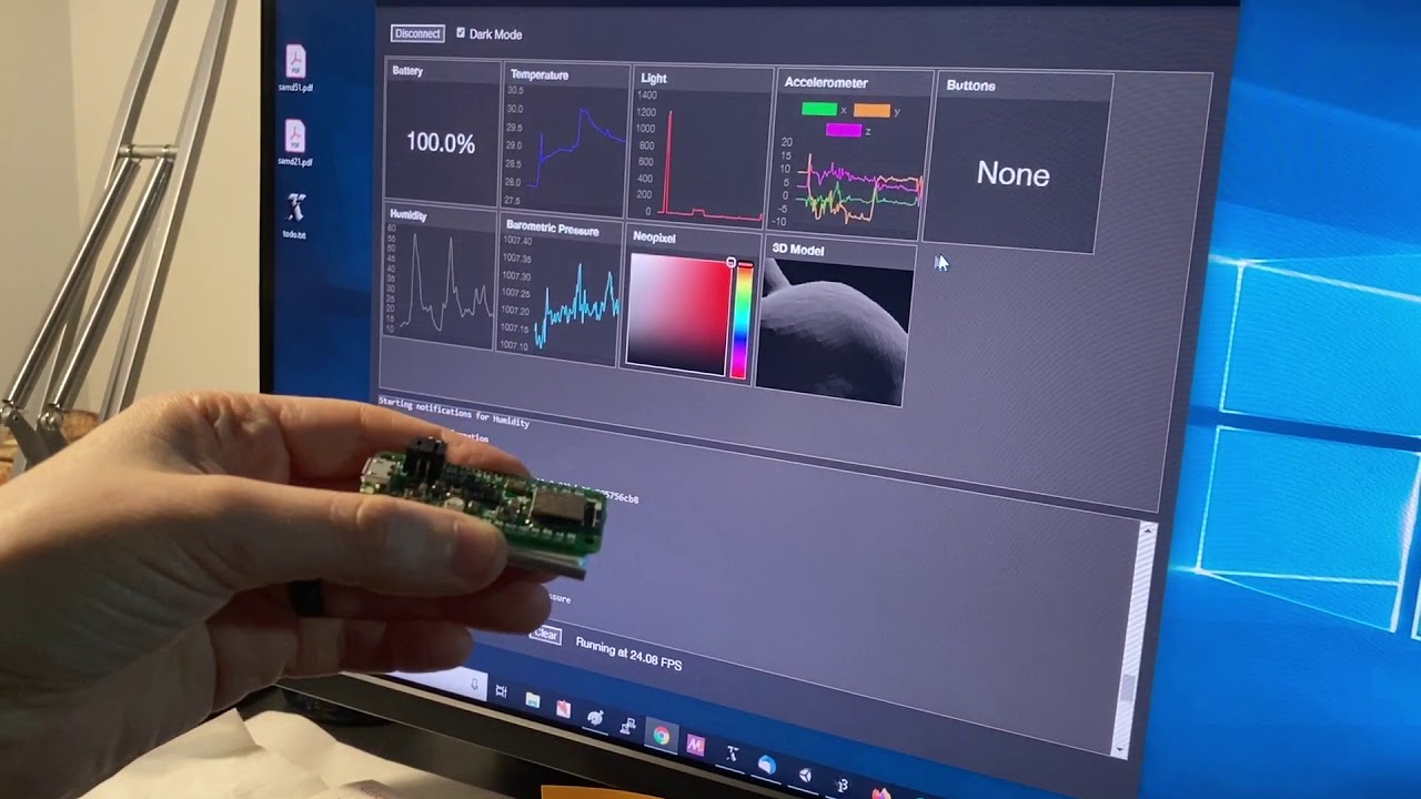
Our new Feather Bluefruit Sense is available in the adafruit shop - its jam-packed with temperature, humidity, pressure, sound, light/color/proximity, and motion/orientation sensors. Even has a lil button! How to test it out? Melissa coded up a dashboard in javascript, using a...
pine bramble
Does anyone know how to lower the brightness for this?
https://github.com/adafruit/Adafruit_LED_Backpack

GitHub
Adafruit LED Backpack Library for our 8x8 matrix and 7-segment LED backpacks - adafruit/Adafruit_LED_Backpack
 old heart
I'm confused, I was messing around with my Arduino and a servo. Then the servo started started acting weird to I tried to restart the program and got a "Problem uploading to board." or something error, then a "An error occurred while uploading the sketch." error. And so I enabled Show verbose output during both compilation and upload. I still have no idea what happened because it was working one second and not the next. I didn't change any code or wires.
Here is the full output log: https://pastebin.com/HjfPPpEL
Please @ me if you respond
 regal matrix
I'm looking at trying to simulate the key press on a resistance based keypad using a 3.3v arduino and an DAC. Does anyone have some advice on what kind of circuit I'd need to build to support this?
The keypad line is at 5v, and it passes that to ground with varied resistances. I was thinking I could use a transistor to give me the control, but I don't know how to move on from here
wraith current
@regal matrix could be pretty simple if you had a 5v Arduino
 dull bison
Anyone that can explain to me why my Led isnt turning on?
lone ferry
Try void LedOn(Adafruit_NeoPixel &led) { -- note the &
 north atlas
Can someone please help me? I am a noob and am setting up this laser but for whatever reasons its not working
Im using the exact config from https://create.arduino.cc/projecthub/infoelectorials/project-007-arduino-ky-008-laser-module-project-a62c94

Arduino Project Hub
The perfect project for any beginner featuring a simple-to-program but powerful laser module, an Arduino board and basic coding functions. By Electorials Electronics.
I have gotten a few things to work like turning on a motor and the blink sketch. I have tried different wires and lasers as well
north stream
I wonder if the laser needs a power lead to be hooked up
north atlas
Thats what I was thinking because where is the power coming from
 buoyant jacinth
any idea if there's more info on "NEOPIXEL_VERSION_STRING" @ https://github.com/adafruit/Adafruit_BluefruitLE_nRF51/blob/a96c8d85229a36eb389e5f2e325f219b9639fefe/examples/neopixel/neopixel.ino#L41 ? I'm using the code and it works fine, only catch is I have a pixel strip w/ 20 led's vs the NeoPixel v2 that's coded into that example. The other NeoPixel_Picker example doesn't work when I tried it.
GitHub
Arduino library for nRF51822-based Adafruit Bluefruit LE modules - adafruit/Adafruit_BluefruitLE_nRF51
pine bramble
Hi!
I have attached a D1 mini - ESP8266 to a led strep and I try to adjust the leds via my google home. I have succeeded to do so with IFTT and adafruit.io. I am using the adafruit package and mqtt protocol to send messages. This works fine up to 3 or 4 hours, but then the D1 gets stuck in some kind of zombie mode, and does not read the incoming messages anymore. I have copied reconnecting from the github page as following. Does anyone know why the D1 is freezing and how I can solve this problem?
When I plug in my arduino device (Huzzah Feather, M0 express, variety of others) to my Windows laptop it connects as the next COM port available. When I click build/deploy in the Arduino environment it builds, then the device restarts and picks the next COM port. So I switch the port in the Arduino environment, hit build/deploy again and it builds and then deploys just fine. The device then restarts back to the first COM port, so I have to change the port in the environment in order to turn on the serial monitor. Has anyone else seen this, and how do you fix it?
@pine bramble The only thing I can think of is to physically plug in the target (M0 Express &c.) only prior to starting the Arduino IDE, not once you've started the IDE.
If I have my serial communications program talking to the M0 target (CPX for example) and I upload, the IDE does the right thing, but my comm program doesn't, as the second time around, /dev/ttyACM1 is current. (The IDE seems to track this by itself).
So my solution there is to (remember to) disconnect my comm program before doing a firmware upgrade on the CPX. (This is all under Linux).
I think SerialMonitor may be a bit more tolerant, there, but I like my other communications program more than SerialMonitor.
mortal ferry
Is there a way to get #define macros to a library in Arduino? It doesn't work by default, and it seems the common wisdom online is that it's impossible. However, libraries like FastLED seem to advertise that you can override their internal settings using macros, which doesn't seem to add up.
@sour tide would you happen to know anything about that? I'm trying to give users an option to restrict how many RMT channels the ESP32 can use for the neopixels.
I have statements like:
#ifndef ADAFRUIT_RMT_CHANNEL_MAX
#define ADAFRUIT_RMT_CHANNEL_MAX RMT_CHANNEL_MAX
#endif
which I'd like the user to be able to override with their sketch. FastLED uses this all the time, but maybe that's for non-arduino applications of that library?
vivid rock
The usual way is that you put in myLibrary.h this code
#ifndef MYMACRO
#define MYMACRO 25
#endif
and then in the main sketch, user can override it by defining the macro before including myLibrary.h:
#define MYMACRO 20
#include "myLibrary.h"
I think the error here is that the Adafruit Neopixel library is using c files, not h files
 sour tide
@mortal ferry I don't know
vivid rock
any library has both .h files and .c (or .cpp) files
mortal ferry
C files can't access header material like this from a .ino file
They'd need to include own separate .h file with the setting
vivid rock
I don't quite understand what you are asking then.
Adafruti NeoPixel library certainly contains an .h file, Adafruit_NeoPixel.h
and any user sketch using that library must have the line
#include "Adafruit_NeoPixel.h"
mortal ferry
I'm trying to figure out if there's any way for a user, from inside Arduino IDE, to pass macro information into a .c or .cpp file inside a library without going in and manually changing the library.
And I don't think there's an obvious method. Clearly you pass information like the core type (ESP32, ESP8266, etc) but those are selected from dropdowns, not done from the sketch.
I guess the core of my question is whether there is any way to get your own macros to the level of universal inclusion that Arduino seems to apply to the core macros, ESP32/ESP8266/ARDUINO_ARCH_STM32 which are accessible with every file regardless of what header files you include
vivid rock
those macros are defined in board definition files, somewhere in /packages/adafruit/hardware/..../boards.txt and passed as flags to the compiler:
adafruit_feather_m0_express.build.extra_flags=-DARDUINO_SAMD_ZERO -DARDUINO_SAMD_FEATHER_M0 -DARM_MATH_CM0PLUS -DADAFRUIT_FEATHER_M0_EXPRESS -D__SAMD21G18A__ {build.usb_flags}
if you are not afraid of manually editing those files, you can add your own macros there
that would make them available to all sketches and libraries
mortal ferry
So, internally, Arduino must add these files as headers to every single source file?