#help-with-arduino
1 messages · Page 78 of 1
 stuck coral
 reef ravine
lol, all the examples out there seem based on the elegoo example
reef ravine
(and only control turning speed 🙂 )
stuck coral
This is way better IMO-
void stop() {
  digitalWrite(ENA, LOW);
  digitalWrite(ENB, LOW);
}

void rightDrive(uint8_t pwm, bool forward = true){
  digitalWrite(ENA, HIGH);
  digitalWrite(ENB, HIGH);

  if(forward){
    digitalWrite(IN2, LOW);
    analogWrite(IN1, pwm);
  }else{
    digitalWrite(IN1, LOW);
    analogWrite(IN2, pwm);
  }
}

void leftDrive(uint8_t pwm, bool forward = true){
  digitalWrite(ENA, HIGH);
  digitalWrite(ENB, HIGH);

  if(forward){
    digitalWrite(IN3, LOW);
    analogWrite(IN4, pwm);
  }else{
    digitalWrite(IN4, LOW);
    analogWrite(IN3, pwm);
  }
}
Oh wait they PWM ENA and ENB in their example... that shouldnt work, that example you linked to @reef ravine is wrong!
Youre welcome
Those pins cant output a PWM signal
 north stream
wait what?
reef ravine
ALL the ones I found do it that way, ya just can't trust the Interwebs...
stuck coral
Well, wonder if you're the only one having issues with variable speed
north stream
idk
reef ravine
from the forum posts I'd say no...
stuck coral
Oh... but their ENA and ENB pins are different
They are just using the H bridge wrong
lol
north stream
it give me error
stuck coral
What is the error? I didnt compile it so thats quite possible
Seems to compile for me
stuck coral
Ah, so you are supposed to, add my functions, keep the definitions, then change the rest of your code to do what
You removed all the pin declarations
north stream
ok
stuck coral
What are you using to send IR signals to this? Another arduino?
stuck coral
You mean transmitter? Like a remote?
north stream
yah
reef ravine
the kit came with the remote right?
stuck coral
Can I see what you are compiling? Pastebin please if you could
stuck coral
I would like a code pastebin
stuck coral
I just said to add my functions, do you want a new example that does exactly what the only one did?
north stream
sorry the vid laggy
stuck coral
You need a loop and void function to compile
reef ravine
What IoT sent was an example of how to change the code, not a complete sketch
north stream
lol
oh
now i get it
ok
ok
thanks for your help so much @reef ravine and @stuck coral
🙂
and sorry cause i took alot of your time
bye
stuck coral
You're welcome @north stream, if you want an example similar to what you had here it is with my code and the old functions removed- https://hatebin.com/rbytavqddg
stuck coral
driveRight and driveLeft take in a speed and a boolean forward or backward and you can use them as you choose to do whichever direction. And see ya
north stream
bye
 river osprey
Is it possible to use a charging backpack with the CPX? When I power it through the battery it tries to charge itself - I am used to using an itsy bitsy m4 which has a specific battery port...
stuck coral
When using the charging backpack, you have to use the battery port on the backpack not the bottom of the itsy bitsy
river osprey
IoT - yes, thank you, i've got the itsy-bitsy all good, it's the CPX that i'm having trouble with. Because it just has a VOUT - not a "usb" so basically if it's plugged in to the battery, it attempts to charge itself...
stuck coral
Got it. So what is the M4 doing in this?
river osprey
nothing - just noting that i've used it successfully.
stuck coral
And yeah, the battery backpack is for the itsy bitsy not the CPX, I dont really see a way to get them to work with each other
river osprey
I have a CPX attached to a Gizmo TFT and I want to utilize a charging backpack so that i can just have the user charge everything via USB then use an on/off switch
instead of having to disconnect the battery to charge it
stuck coral
If you had a USB breakout, you could make it work

Simple but effective - this breakout board has a USB Micro-B connector, with all 5 pins broken out. Great for pairing with a microcontroller with USB support, or adding USB 5V power to a ...
But then you cant program the same port you charge
river osprey
I'm not concerned about the re-programming, and I might have to go that route...
i am trying to fit everything into a fairly small enclosure - as it's for a costume...
is there an itsy bitsy with bluetooth?
stuck coral
The ItsyBitsy nrf52840 express
river osprey
thanks - i wonder if this will work with the TFT gizmo - although I have other displays i could use... hmm... lots to consider... thanks you
 safe shell
Looks like VOUT is like VHI on the Itsy https://learn.adafruit.com/adafruit-circuit-playground-bluefruit

Adafruit Learning System
Circuit Playground Bluefruit: Everything amazing about Circuit Playground, now with the power of Bluetooth!
river osprey
Thanks Anecdata - i really would need the CPX to have a dedicated BAT / USB for this to work. Originally i thought my project was going to need the accelerometer and other items on the CPX, but it turns out I don't, so it'll actually be better for me to use an ItstyBitsy with a TFT breakout for faster processing, smaller packaging, and guarantee it will work with the charging.
safe shell
Processor speed is a good point. The backpacks do work really well with the ItsyBitsys, I've had a few in place for quite a while.
 thorny lintel
Hey guys, I have an RFID 134.2khz implant and I am trying to turn the pin13 LED off and on with the chip
I purchased a 134.2KHz FDX-B EM4305 Reader and have connected it to my Arduino Nano and it reads the data on the chip fine through the Serial Monitor
I have found a sketch online that allows you to turn the LED off and on if you send 1 or 0 through the serial monitor on IDE, but how can I make it turns off and on if the reader reads the code that's on my RFID implant?
I've tried putting the string of numbers in but it doesn't work, if I put higher than the number 9 in the text goes from blue to black
Would really appreciate any help, has been quite daunting to google so far!
Here's the code I am using, I just need to have the state 'x' be the data/numbers/string from the RFID chip
I assume the chip is using 0-255 data
And I also assume the sketch is using a different form of number "data" or whatever the term!
This is the code I get back from my chip if I scan it once with the serial read sketch
Would appreciate any help 🙂
 cedar mountain
So if you wanted to key off the first byte there, you'd be checking if (state == 170), for instance.
thorny lintel
I'll give it a change to 170 and see if it works
Doesn't matter that the 170 is no longer blue, like the 1 was?
Sorry for being disgustingly new
cedar mountain
But it's unclear how you will know to turn off the LED, since I presume the reader won't sent anything if it doesn't read a tag.
You don't want it in quotes.
thorny lintel
There we go
I was hoping it's just, "If read rfid data turn on, if read rfid data and LED is on, turn off"
cedar mountain
You can do that, your code just needs to keep track of whether the LED is on or off.
thorny lintel
Still not liking just 170, still also black rather than blue text, if that's an issue/signifies something
Thanks for your help by the way, appreciate the time
cedar mountain
As written, the code will just blink the LED extremely briefly because any non-170 byte will turn it off. You would want something like:int led_state = 0; void loop() { if (Serial.available() > 0) { if (Serial.read() == 170) { led_state = !led_state; digitalWrite(13, led_state); } } }This will toggle the LED when it sees the first byte in the RFID tag sequence.
thorny lintel
Like I love you but I hate you
Whole day
WHOLE day
Googling, searching, slicing premade code
And in a single discord message you do it
Ah man thank you, honestly thank you
cedar mountain
No problem. You described your situation well and provided everything necessary for a quick fix. 💯
thorny lintel
Either I'm smart or I've asked for help enough times to know how to format a question 😉
cedar mountain
Ha, neat! Our cyborg future in action! 🤖
 pine bramble
not really an arduino question, but more an atmega328 question
if I hooked up a 32. 768khz crystal to a 328p, could I use it as a low power RTC?
basically the idea is to have a switch that turns the device "on and off"
well, not really on and off, but switches between low power timekeeping mode and full power play mode
it's going to need to last a while off of 2 AAAs, so power saving when not in use is key
when you turn it "off", it should keep track of how much time has passed since you turned it "off", and when you turn it back "on", it will use the amount of time that passed to simulate game events
ex: if it's been off for 2 hours, and your pet's food level decreases at 1 tick per 5 minutes, then decrease it by 24 when it powers back on
giving the illusion that the hunger bar has been decreasing even while it's turned off
i don't want to use a separate RTC for this as that will add more cost snx complexity to the project
 north stream
This writeup has some useful information http://www.home-automation-community.com/arduino-low-power-how-to-run-atmega328p-for-a-year-on-coin-cell-battery/
Home Automation Community
An Arduino Uno runs less than one day on a 9 V battery because it uses about 45 mA current. Using an Arduino Pro Mini, with a simple modification, the power consumption goes down to 54 μA (0.054 mA)...
Possibly also relevant: https://www.microchip.com//wwwAppNotes/AppNotes.aspx?appnote=en592059
AN2648 Selecting and Testing 32 KHz Crystal Oscillators for AVR Microcontrollers This Application Note summarizes the crystal basics, PCB layout considerations, and how to test a crystal in your application. A crystal selection guide shows recommended crystals tested by expert...
 heavy slate
i use a TFT 2.8" no touch from china, but after use graphictest example , i receive a only white screen. PLs help me
my wire connect:
VCC-3.3v
GND
CS-10
RST-8
SDI(MOSI)-11
SCK-13
LED-3.3
SDO(MISO)-12
here is the phenomenon
north stream
You probably need to connect more pins like MOSI (data), DC (data/command), EN (enable), and RS (reset).
heavy slate
You probably need to connect more pins like MOSI (data), DC (data/command), EN (enable), and RS (reset).
@north stream Sorry my fault for not complete comment, i already connect all pin of spi peripheral but only show white screen
oh this flink 2 times, but after that it so the white screen =(((
north stream
What software are you using?
north stream
What code are you using?
heavy slate
examples name graphicstest of this library
https://github.com/adafruit/Adafruit_ILI9341

GitHub
Library for Adafruit ILI9341 displays. Contribute to adafruit/Adafruit_ILI9341 development by creating an account on GitHub.
north stream
Do you get anything on the serial monitor?
 frosty thistle
Hi all, I have a TFT question also. I am running a HX8357 using the adafruit library + the GFX library. It works just fine, but it turns out that the draw to screen is blocking. (same project with the 4digit 7seg displays) and everytime it draws, it blinks the seven seg display).
Is there any way to operate this non-blocking?
frosty thistle
yeah
stuck coral
Are they SPI or I2C? I forget
frosty thistle
I2C
stuck coral
Ah, so maybe, but you would probably need to modify the tft library.
frosty thistle
The TFT is running off the hardware SPI pins on the MCU
north stream
I suspect the TFT library sends the whole screen in a single, blocking, operation, which freezes the LED multiplexing while it's in progress. If so, the fix would involve rewriting the TFT library to send the data in pieces, and return control in-between to let you continue the LED multiplexing. That would be fairly involved, but I could well be wrong.
stuck coral
Depends on how much of the time is SPI transfer time
frosty thistle
I guess it could get worse, so far I am just writing a single string to the TFT. Plan is quite a bit more info being displayed.
stuck coral
See, Ive been thinking about this issue recently, micros have so much memory and processing the limitation in software is now IO. With that hardware it is technically possible to send a giant block of data over SPI while your processor sends I2C commands but the arduino software isnt really tailored to do that.
Using DMA or direct memory access, what you want is totally doable, just with a higher level of skill involved and not with Arduino framework
north stream
I usually take the lazy way out and use a separate chip to do my LED multiplexing
stuck coral
Well, not that you couldnt do it, but the libraries are not written for it
frosty thistle
Gotcha. In my preliminary googling of if this was possible, I saw some things that possibly hinted at something like that. Thought I would pop in here were you all are familliar with the Adafruit libs I am using to see.
north stream
I'm not familiar with all the innards of all the libraries, hence my generalizing
stuck coral
Yeah, the answer to that question is, how much time do you want to dump into it, or just buy a dedicated hardware solution like bodger says
frosty thistle
like another mcu to run the LED's?
north stream
Something like a MAX7221 or HT16K33 to run the LEDs. You could use another MCU, but since there are dedicated LED controller chips available, I just use those.
frosty thistle
Ah, I see.
I have not used the MAX before, but did come across it. It looked like I needed two to run a single 4d7s display, and was not sure if I could run two of those displays with four chips
north stream
The MAX7221 should be able to run up to 8 7-segment digits.
stuck coral
I think there are probably chips just for those 4 digit displays, they are popular
frosty thistle
I would be willing to try that route. Think it would solve this problem with TFT blocking?
stuck coral
No, but you wont need to constantly update the GPIO expanders with I2C
Sadly many Arduino SPI operations are blocking
frosty thistle
Oh i see, that chip handles all that?
north stream
My thinking is that it would solve the "LED blinking" problem, as the LED driver would continue to update the display while the Arduino was busy.
frosty thistle
got it. Thanks guys, Ill see if I can find some with quick shipping!
 plush pecan
Hi all, I may be overthinking this but I have 4 relay objects defined and I need to loop through and do the same action on all 4. What's the best way to do this with a FOR loop?
//Startup Light Blink
relay1.blink(100,100,0,20);
relay2.blink(100,100,0,20);
relay3.blink(100,100,0,20);
relay4.blink(100,100,0,20);
north stream
Probably store the relay objects in an array and iterate through that. I don't know the type, so I'll just use "Relay" to illustrate: ```c
#define NRELAYS 4
static Relay relays[NRELAYS] = {
new Relay(1),
new Relay(2),
new Relay(3),
new Relay(4)
};
void setup()
{
int i;
for (i = 0; i < NRELAYS; ++i) {
relays[i].begin();
}
}
void loop()
{
int i;
for (i = 0; i < NRELAYS; ++i) {
relays[i].blink(100, 100, 0, 20);
}
}
@north stream you are my new best friend. thank you, seriously!
north stream
You can get even fancier and use pointer math, but that's a start
 narrow jackal
Can control encoders track the degrees of a stepper motor? Or do I need a motor encoder?
 unborn saffron
What are control encoders?
 thorny current
ets Jan 8 2013,rst cause:4, boot mode:(3,6)
wdt reset
load 0x4010f000, len 3584, room 16
tail 0
chksum 0xb0
csum 0xb0
v2843a5ac
~ld```
Anyone know why my Arduino is resetting when I try to run the "Sweep" code with a Servo? It's a Wemos D1 Mini leaden light
@north stream bro how we control air conditioner or tv type of things with node mcu but it have running on high voltage so how to control it
Any one help me for this 👆
 woven mica
You have to use a relay, but its dangerous to do with mains voltage.
leaden light
Relays used for fan light bulb etc but what about the instrument running on high voltages
woven mica
what instrument?
woven mica
TVs still run on 230V AC
leaden light
Is ac and tv can run with relay
woven mica
Yes
leaden light
My friend tell me that there is need of protection circuit
woven mica
But its dangerous
 plucky tundra
hi, i am using a bluno beetle for my project and the thing is, when i used usb to power my board, it can send packets with readings from a MPU6050 with BLE but when connected to power supply of 4.8V, it can still send packet but the returning values are all 0 no matter how much we move the imu unit. does this imply that the MPU6050 isn't getting enough power?
woven mica
Well, what protection you need depends on where you live
leaden light
And how can be detect it from mobile because it has already transmitter and receiver
So how we detect that 🙄
woven mica
In europe we have earth safety connection
leaden light
Hmm
woven mica
@leaden light why dont you just buy Sonoff, its the exact thing you want
leaden light
Ohh really I never heard about that so 😅
Ty for reply and solve my question 🙏
@woven mica can know are you an engineer??
woven mica
Well, i am studying electronics
leaden light
Nice 👍,
thorny current
For the life of me I cannot control this servo with my arduino
pine bramble
probably a stupid question, but now does waking up the Arduino using a pin change interrupt work?
tl;dr: I need the atmega to wake up in one of two ways
first way is from TIMER2: this should be called every second by the asynchronous timer hooked up to a 32.768khz crystal
all this ISR needs to do is increment a seconds counter and then go back to sleep
the other way is from a pin change interrupt: upon the user hitting a button, I want the atmega to get out of sleep mode and turn back on, allowing the user to do stuff until they hit the button again, where it goes back into sleep mode
so when the ISR finishes, does it go back to sleep? or does it continue to execute after the last sleep_cpu() call?
nvm, looks like it continues executing after the interrupt
is it safe to put it back to sleep while inside of the ISR?
 wraith current
@thorny current show your code.
@leaden light you don't need to deal with mains voltage. Just control an IR led and emulate the remote control for the AC and the TV. There is already an arduino library that deals with many AC units : https://www.instructables.com/Air-Conditioning-web-controlled-by-Arduino/

Instructables
Air Conditioning Web Controlled by Arduino: Hello thereThe high temperature of this summer, make me think to this project. May be there are similar on the internet, but I didn't find.This project is based on arduino, and runs well on boards bigger than UNO, which has not so mu...
leaden light
🙏.
 flat folio
Hi all, I am having very weird issues with two Adafruit Grand Central M4s. In short, its almost like they are corrupted or something. I have trouble uploading code to them, I always have to hit the reset button twice to upload. I can only sometimes access the serial monitor -- many times it will just freeze until I hit the reset button twice. After I am able to upload code after trying many times, its like the controller is only reading some code. I have some fairly basic code and sometimes it will not respect the delay command. Sometimes it won't respect the milis command. And sometimes it does nothing at all -- when this happens and when I can open the serial monitor, nothing comes across screen and nothing happens with my lights (using Neopixels). I can upload many variations of this same code I am using to a Metro and other controllers and it behaves normally. I recently saw the post on the adafruit forums to upgrade the bootloader which I have done but that does not help any. I have tried uploading from different computers and using different cables but nothing seems to fix the issue. Any ideas would be greatly appreciated... I am at my wits end on what to do. Thanks in advance.
 elder hare
need som help with pinout here! im using this library -> https://github.com/mrfaptastic/ESP32-RGB64x32MatrixPanel-I2S-DMA (using the default pinout)

GitHub
An Adafruit GFX Compatible Library for ESP32 and HUB75 RGB LED Panels. Using DMA to drive the panel for higher refresh rates. - mrfaptastic/ESP32-RGB64x32MatrixPanel-I2S-DMA
this is the ESP32 im using! now is it fine for me to use the default pinout?
 green heath
Do i need to limit the current coming into a buckdown from a 9 volt battery? My knowlegde tells me if i dont put in a current limiting resistor the current will be very very high. But i am unsure of what happens inside the buckdown
 vivid rock
@green heath the current through buck converter is determined by what you connect to its output. If you do not connect anything, current will be close to 0. If you use it to power microcontroller or similar electronics, it will be pulling maybe 200- 500 mA- not a problem.
In general, limiting current using resistors is not a good idea (with some notable exceptions like current limitng for LEDs).
green heath
But what if i accidentally short it though? Should i use a diode for that?
vivid rock
good buck converters usually have built-in short-circuit protection
but still, try to avoid shorting it
green heath
Yeha i get that but i am that kind of person that can put a 5v output straight into a ground
And then only afterwards thing that maybe i shouldnt do that
vivid rock
well, then maybe putting a 10 Ohm resistor on the input might work during your experimentation
but remove it once you have finalized your design
green heath
I dont quite understand my buck tho
It had an enable, ground, common and adjustable. And a postive output
Along with with the array of voltages
I havent found any data sheet of it and i am totally lost
 grand basin
Hello, I need to use an interrupt in my program which stops my microcontroller from sending UART data to another device for the duration of the time I hold down a momentary push button. The other device is a DSP which has ‘patches’ that I can toggle through but my microcontroller which transmits serial MIDI crashes the DSP because it’s continuing to run the MIDI script.
I pretty much understand how to initiate an interrupt using the guide on the Arduino website, but I don’t know how to take that information to temporarily ‘silence’ the UART data, and arrange it so that it lasts as long as I have the button depressed. It sounds super easy I just haven’t found a guide to this specific application anywhere online. Can someone point me to where I can find this information? Thanks!
vivid rock
create a global variable button_pressed ; in your interrupt routine, set this variable to true when the button is pressed and to false when it is released, and in the place in your progrma where you send UART data, add an if condition:
if (!button_pressed) {
    //send the UART data
}
just remember that the variable needs to be declared as volatile
north stream
@green heath There are just 4 pins. Input voltage is hooked up with positive to IN+ and negative to GND. Output comes with negative from GND and positive from VO+. The enable input can be connected to the input positive to turn on the converter.
vivid rock
@grand basin you would need to setup the interrupt as a change interrupt, so it is triggered both on button pressed and button released
and you would later need to worry about button debouncing
grand basin
Okay great, thank you!
vivid rock
of course, an even easier solution without any interrupts is just checking the voltage on the button pin before sending uart data:
if (digitalRead(PinButton)) {
    // send UART data
}
assuming that the PinButton is declared INPUT_PULLUP and pressing the button pulls it low.
grand basin
Oh, so this like putting a crimp in the hose on the UART pin being used?
pardon my crude analogies I'm still new 😆
vivid rock
well, we are not doing anything specifically with UART pin, we are just not sending anything at all if PinButton is low
grand basin
Oh great, got it. I'll give it a whirl!
 tame hound
Is anyone able to help me with arduino not being recognized by my computer
I connected it and it shows this on device manager
"USB Serial Port"
I tried updating the drivers manually by choosing the file from the software called "drivers" but it didn't work
woven mica
What arduino, issa clone?
tame hound
It says RedBoard on it
Idk it's what my school provided
It uses the Arduino IDE platform
Except it's not being recognized on my computer
north stream
An Arduino will show up as a USB serial port, as it uses serial communications.
tame hound
Im not sure why the software doesn't recognize it however
It says Serial port not selected.
And it's not showing up in tools ----> Ports
north stream
Ah, it should show up in Ports.
tame hound
Yes
Which is the problem
I figured the issue out
I just searched up the drivers from online for the redboard and installed it and it worked
jesus that took 2 hours of my day
lol
north stream
I'm glad you figured it out! It's annoying it took that long, I have days like that too.
tame hound
Thank you, yeah such a simple issue tbh
 strange ether
@leaden light you don't need to deal with mains voltage. Just control an IR led and emulate the remote control for the AC and the TV. There is already an arduino library that deals with many AC units : https://www.instructables.com/Air-Conditioning-web-controlled-by-Arduino/
@wraith current hi! very helpful. but i wonder if there is the same project but in raspberry (cause rpi has wifi)
Instructables
Air Conditioning Web Controlled by Arduino: Hello thereThe high temperature of this summer, make me think to this project. May be there are similar on the internet, but I didn't find.This project is based on arduino, and runs well on boards bigger than UNO, which has not so mu...
green heath
@north stream okay but then how do i get the right voltage out of it. With that setup it just forwards the 9 volt
 neon cobalt
I'm new with electronics and I wanted to know which programming language an Arduino uses, which you recommend, how do I put code into a Arduino, and what do I use to make the code which is able to transfer the data to the Arduino?
grand basin
@neon cobalt I'm not an Adafruit rep and I'm very new myself, but you use the Arduino IDE to program and upload your program to the Arduino hardware. The language is [based on?] C++
neon cobalt
Thanks alot
north stream
@green heath Maybe you have to solder one of the jumpers to set the output voltage?
green heath
I found a picture on ali that told me to cut the adjustable and solder
But it didn't work
All around terrible design
😅
north stream
It's a clever enough design, but not easy to use, especially without documentation
green heath
Well
I either broke it
Fried it
Or soldered it wrong because it just forwards the battery voltage
Even the adjustable is unresponsive
north stream
It could be that it's a boost converter not a buck converter
What kind of load do you have hooked up?
green heath
9 volt battery
And i am measuring the output with a multimeter
Well i got it for free some work i did so nothing is lost
Well i am quite dumb i soldered ground to output
Input
Now i get 7 volt😅
My battery gives 7 volt now great
I am going to unsolder it and throw it away lol
neon cobalt
What are adruino "UNO" used for?
north stream
You probably need more load than a multimeter for it to regulate
You can use an Arduino Uno for all sorts of things, it's a versatile little unit.
neon cobalt
Ok
green heath
Well i am not going to plug it into my atmega if says 7 volt :/
pine bramble
I’m using the standard “button cycler” example code given by adafruit Neo Pikel library and achieving very wired results.
The picture with the lights shown is RED
I’ve defined the proper amount of pixels in the strand.
stuck coral
Looks like you are not using the right supply or logic voltage to me
pine bramble
5v power supply at 3amps max draw
stuck coral
What logic voltage are you using?
pine bramble
Pardon?
stuck coral
What voltage do the pins on that micro output? 3.3V or 5V?
pine bramble
I have 5 volts coming into the arduino from the supply via bus bars, the 5v rail is connected to provide the arduino with power. No power is actually coming from the arduino. Common ground, and data. That’s it
stuck coral
That doesnt tell me anything about the logic voltage, can you take a picture of the underside of that blue board you have pixtured for me?
pine bramble
The blue board, like the arduino.
stuck coral
Yes
wraith current
@strange ether use an esp8266 board of you want wifi
stuck coral
Either you are not using the right color config, the wrong logic voltage is used, that platform wont work with the selected library, or you have a bad connection
pine bramble
But the library worked a few weeks back just fine, nothing has changed as far as I’m aware
stuck coral
Okay, looks like a 5V arduino, 3,3V micros have a second regulator if I remember right. And this is a new issue? Same PSU?
Same code? Exactly
pine bramble
Same code. It’s the basic button cycler example with define pix”es changed from 16 to 15 to fit my strand.
The power supply worked yes, same one
stuck coral
DId you rewire it between then and now?
stuck coral
Yes but it looks to me to be bad connection out of my range of options because from my neopixel experience the pixel count doesnt cause that issue because of how the protocol is laid out. Only other option I see is if you changed the LED type
pine bramble
But here’s the kicker, with a different string of example code “RGBW strip test” it works fine.
stuck coral
Well yeah
You changed the LED type
If those are RGBW leds, sending RGB data will do that
pine bramble
But the button test worked prior without describing “RGBW”
stuck coral
Sorry I misread, then you are sending RGBW dato to RGB or GRB strips (I forget which is the default)
pine bramble
It seems GRB is default
stuck coral
You should read how the data protocol works for those LEDs, then what I am saying will make perfect sense. So change the LED type back to GRB and let me know how that works
pine bramble
We reinstalled the library, seems to be working, but what is the dif. In GRBW GRB and RGB. I’m still learning sorry if it’s obvious.
stuck coral
So these LEDs have 4 pins, data in, data out, power, and ground. You connect data in of the first LED to your arduino, and the output of that goes to the input of the next LED. So you are just using this super simple protocol to send a 2d array over one line, where the first LED takes the first three (Or if RGBW 4) values it reads from the data input, then after it gets a value it just resends the rest of the data to the next LED, which will get the next 3 (or 4) bytes then pass it along until you get to the end of the strand until the arduino stops talking
So if you are say, trying to send a three long strip all greed GRB values, then the data would look kinda like - 0xFF, 0x0, 0x0, 0xFF, 0x0, 0x0, 0xFF, 0x0, 0x0
But if its a RGB LED, it sees red red red, not green green green
And if its RGBW, it sees red and white, blue, off
Does that make sense?
Are you sure those are GRB?
I see a blue and a white in the same element
neon cobalt
why does the frequency matter in a arduino?
stuck coral
I was reading your earlier conversation, so let me give a slightly different twist on what the person you were talking about said
A raspberry pi is a single board computer, it can run multi user operating system like linux or BSD, it has a lot of memory from 1-4GB, and is fast enough to run desktop or server applications. A arduino is a group of microcontrollers with specific software support with the arduino framework. Microcontrollers are basically entire computers on a tiny chip with a processor, memory, peripherals, and interfaces but they are very low power both from a power consumption standpoint and computational standpoint
neon cobalt
Ok
stuck coral
So if you wanted a microwave, all it needs to do is register button presses and run a basic display with some other control stuff, it makes no sense to put a whole computer in it, you want it to turn on instantly without the overhead of a multi user OS, and have it sip power. Luckily micros are tiny computers but for $3
So increasing the clock on a micro does the same thing as on your computer, it lets the micro step through an application faster
Like your computer or the pi, there is a processor clock speed with can increase to make your computer run faster, but it will consume more power
However, there are many thing the micros dont that the desktop CPUs do of course, like MMUs
neon cobalt
How much memory can a Arduino hold from lowest to highest.
stuck coral
UNO has 2KB, a feather M4 has 192KB, can go up from there
There are a few that are smaller than 2KB but most are within that range
The Arduino Portenta H7 has a whopping 1MB of RAM
stuck coral
Inputs let you read a state, a output lets you set some sort of state. If you are talking in context of the arduino framework I imagine you are talking about the peripherals? Like setting a pin up as an input or an output?
neon cobalt
In context of "Analogue"
stuck coral
Well I assume you mean the pins, so on GPIO of a microcontroller, there are pins which can be digital or analog, and each can be set as an input or an output (there is more detail here, note this is simplified). So if I say set a pin to be an output, and its digital, I can use digitalWrite() to set a pins voltage to be HIGH or LOW. Or I could take an analog pin, and set it up as an input, and read a voltage from another device like say a battery voltage from a voltage divider with analogRead()
 pulsar junco
DC
neon cobalt
ok
pulsar junco
you can simulate AC output though
neon cobalt
ok Thank you.
pulsar junco
well actually you can control chips that simulate AC output, I'm not sure if you can do it with a bare arduino
neon cobalt
Like digitally simulate ac current like a oscillator or physically create ac?
pulsar junco
you can approximate a sine wave with some external components.
you need a negative voltage to do it so you can't do it with a bare arduino IIRC
*negative and positive voltages
neon cobalt
Ok
strange ether
@strange ether use an esp8266 board of you want wifi
@wraith current for arduino no?okey thanks
wraith current
@strange ether yes, you can use the Arduino framework on esp8266 boards.
strange ether
okey thanks
 true nest
I've got a TeensyLC that I think is dead. The board doesn't appear on my windows (no device connected sound) or linux (doesn't appear on lsusb output) machine. PROG + GND shows 3.3v, goes to 0v when button is pressed. I also get 3.3v and 5v on their respective pins. I've tried holding the programming button when plugging the USB cable in, as well as holding the programming button for 15 seconds. Is the board in fact dead?
north stream
There's not a lot left. In the Teensy LC, the USB data lines are connected to the MCU pins via 33Ω resistors, so if the MCU has power and the clock is running, there ought to be some sort of response on USB. It is possible that it was loaded with a software configuration that prevents it from enumerating, or it's being held in reset, otherwise it seems like a hardware failure (could be as simple as a cracked solder joint).
true nest
that's what I feared. i think I uploaded the wrong code for it. won't make that mistake again.
north stream
If it's just the wrong code, it can probably be unbricked by flashing a new bootloader, however I don't know how to accomplish that.
neon cobalt
what are the uses for the arduino lilypad
 tall pine
its meant for wearables and e-textiles. It can be sewn directly to fabric and you can use conductive thread to make a wearable circuit board almost
neon cobalt
so is it machine washable?
tall pine
I'm gunna go out on a limb and say no
neon cobalt
ok
 crystal fossil
I would do further research, but from a quick google search, it seems that they are hand washable.
neon cobalt
What is the arduino mega used for?
 fresh pendant
How do I use capacitive touch inputs on Feather M4 in Arduino?
 odd fjord
@fresh pendant Did you try Freetouch https://github.com/adafruit/Adafruit_FreeTouch says its only been tested on SAMD21 but maybe....
fresh pendant
it seems that it doesn't work. I decide to use pushbuttons instead.
it's not critical, it just would have been nice
elder hare
say i have a String !testMe something there is 8 character to the word something how can i fetch/get that workd after the space ?
 leaden walrus
@fresh pendant do you know how the hack works in CP? using a 1M resistor
fresh pendant
Yeah I vaguely know about it. wanting a demo right now meant not trying to implement a software touch library right now 🙂
leaden walrus
@elder hare strchr or strtok maybe?
elder hare
@leaden walrus hmmm i tried this
Serial.println(payload_str.substring(6, 10));
and i wrote !neon blue
but it returns lf :S dunno where that's coming from :S
elder hare
yea
lol i wrote !neon green and now i get calf
xD
hmmm
maybe there is something more in the string :S
leaden walrus
maybe. what platform are you building on?
elder hare
oh yes!! there is ALOT more in the string xD
leaden walrus
that'd explain it 🙂
elder hare
yupp 😛
leaden walrus
ignore my suggestions above. those are lower level C funcs.
the arduino string lib should make it easier
frosty thistle
I got the MAX7221's in and they work. Had to shift the TFT to software SPI, but thats fine in this application. Thanks again!
neon cobalt
what are arduino nano's used for specificaly
woven mica
For controlling electronics
 low gorge
Hey guys i need a little help
i want to let my led's blink based on the potentiometer, and when the potentiometer is all the way to the left i want it to be the slowest and all the way to the right as its fastest but it does the opposite. could anyone help
?
const int LED1 = 9;
const int LED2 = 3;
const int analogPin = A0;
double interval = 0;
void setup() {
// put your setup code here, to run once:
Serial.begin(9600);
pinMode (LED1, OUTPUT);
pinMode (LED2, OUTPUT);
}
void loop() {
// put your main code here, to run repeatedly:
interval = (analogRead(analogPin) / 2 );
if (interval == 0)
{
digitalWrite(LED1 , LOW);
digitalWrite(LED2 , LOW);
}
else
{
digitalWrite(LED1 , HIGH);
digitalWrite(LED2 , HIGH);
delay(10);
digitalWrite(LED1 , LOW);
digitalWrite(LED2 , LOW);
delay(interval);
Serial.print("interval: ");
Serial.print(interval);
Serial.println(" ms");
}
}
that's my code
 sinful estuary
One thing you might want to add is pinMode(analogPin, INPUT); in void setup()
low gorge
alright imma do that give me a second
added it
have you got any idea how i could solve it?
i've tried many things already like switching the HIGH, LOW and changing the delay
sinful estuary
Really sorry, I do not know why the direction would be switched, based on the code, as it seems sound. Perhaps you could check the potentiometer wiring?
low gorge
i'll have a quick look i believe it is where it supposed to be tho
well i switched the wiring, and now it works however i believe that the left side of the potentiometer is not supposed to be connected to ground am I right?
i mean the 5V output
and the right side of the potentiometer is connected to ground
noe
now*
sinful estuary
Hmm, I wasn't aware of any limitation on which side of the potentiometer can be connected to 5V and ground, is there any such thing? Sorry mate, unsure with this.
Hello, I am having some issues with interfacing a TEA5767 and the 7 segment HT16K33 backpack over I2C. Have connected the data pins and clock pins accordingly, and the addresses do not clash (0x70 for HT16K33, 0xC0(w) & 0xC1(r) for the Radio).
When only one of the two is connected, the connected item functions as expected. However, when I connect the radio and display to the uC (Arduino Pro Mini), neither of them work. Could someone please help me out?
(Everything is receiving regulated 5V)
#include <Adafruit_GFX.h>
#include <Adafruit_LEDBackpack.h>
#include <Wire.h>
#include <TEA5767N.h>

Adafruit_7segment matrix = Adafruit_7segment();
TEA5767N radio = TEA5767N();
double frequency = 87.50;

void setup()
{
  Wire.begin();
  radio.selectFrequency(frequency); // pick your own frequency
  matrixSetup(); //own method
  freqPrint(frequency);  //own method
}
void loop() {}
void freqPrint(double inFreq)
{
   inFreq = inFreq * 10;
   a = (int)inFreq;
   matrix.writeDigitNum(4, a%10, false);
   a = a/10;
   matrix.writeDigitNum(3, a%10, true);
   a = a/10;
   matrix.writeDigitNum(1, a%10, false);
   a = a/10;
   if(a == 0)
    matrix.writeDisplay();
   else
   {
    matrix.writeDigitNum(0, a%10, false);
    a = a/10;
    matrix.writeDisplay();
   }
}

void matrixSetup()
{
  matrix.begin(0x70);
  matrix.setBrightness(1);
  matrix.writeDisplay();
}
Hmm, I wasn't aware of any limitation on which side of the potentiometer can be connected to 5V and ground, is there any such thing? Sorry mate, unsure with this.
@sinful estuary I asked my teacher so there isn't such thing so problem is solved now thanks bro!
elder hare
namespace outer {
inline namespace inner {
  void foo();
}  // namespace inner
}  // namespace outer
gives
this declaration has no storage class or type specifier
@elder hare
Post #5 here:
https://forum.arduino.cc/index.php?topic=37232.0
from TRON007, Sep 13, 2009, 10:28 am
elder hare
@pine bramble ty but i got it to work 🙂
made a settings.h and settings.cpp and got it working 🙂
low gorge
could anyone review my simon says script?
it keeps repeating itself while there was no button clicked
north stream
Possibly?
low gorge
it's a little long is it a problem when i paste it here/
?*
don't mind the names of integers, it's in dutch
 obtuse spruce
@low gorge it doesn't work because you don't wait for the user to press the buttons.
low gorge
oh
obtuse spruce
Also you can't test for them like that.... You must see if there user is pressing any of the three.. and you must wait for the button to be released before checking it again
low gorge
how can i do that? any suggestions
i'm really frustrated by the fact that i just can't get it to work
obtuse spruce
Think about just this but if code:
  teller = 0;
  while ( level >= teller )
  {
    if (digitalRead(knopgeel) == HIGH)
    {
      antwoord[teller] = 2;
      delay(500);
      teller++;
    }
If it was level 5 and I held down the green button... You'd fill upantwoord all with green even though it was just one press
low gorge
yeah that's not supposed to happen
obtuse spruce
You need to wait for the line toLOW before looking for the next button press
obtuse spruce
My first suggestion: ignore the game problem for now and just focus on writing a single function the waits for the user to press one of the three buttons, then waits for that button press the finish, and returns the number of the button.
Call that function from loop and flash the corresponding light when you get it
 ornate horizon
Hey everyone! Can someone tell me if this is a programmable board or is it a shield/module to be added to a separate board?

eBay
The entire solution takes up the least amount of printed circuit board area. Due to the light and screen difference, the item's color may be slightly different from the pictures. Supporting three modes: AP, STA, and AP+STA.
I can see it says development board, but I haven't worked out what that means :/
obtuse spruce
ESP32 is a programmable MCU - but without clear development support from the supplier - why would go that route? If you're buying just one or two to develop a project with - spend more and get a board from a supplier that has full documentation on line, and clearly has done the work to have it supported and functioning in one or more development contexts.
vivid rock
@ornate horizon it is certainly a programmable board
 rose yarrow
I have a Bluefruit LE uart friend that I am wanting to use with my phone. I can’t get it to communicate with the digital pins I want it to.
It always comes up with this message too
 rugged mirage
So if I have a timer match interrupt setup on my arduino but it doesn’t seem exact enough. Do I need to account for the time it takes for those instructions to run?
The interrupt itself only runs one command. It increments a value every 54000 steps at a 256 prescaled 16mhz clock. Can I chock up the inconsistency to a cheaper oscillator in the cheap Chinese arduinos I test on?
cedar mountain
Can you quantify the inconsistency you're seeing?
sinful estuary
Hello, I am having some issues with interfacing a TEA5767 and the 7 segment HT16K33 backpack over I2C. Have connected the data pins and clock pins accordingly, and the addresses do not clash (0x70 for HT16K33, 0xC0(w) & 0xC1(r) for the Radio).
When only one of the two is connected, the connected item functions as expected. However, when I connect the radio and display to the uC (Arduino Pro Mini), neither of them work. Could someone please help me out?
(Everything is receiving regulated 5V)
 #include <Adafruit_GFX.h>
 #include <Adafruit_LEDBackpack.h>
 #include <Wire.h>
 #include <TEA5767N.h>

 Adafruit_7segment matrix = Adafruit_7segment();
 TEA5767N radio = TEA5767N();
 double frequency = 87.50;

 void setup()
 {
   Wire.begin();
   radio.selectFrequency(frequency); // pick your own frequency
   matrixSetup(); //own method
   freqPrint(frequency);  //own method
 }
 void loop() {}
 void freqPrint(double inFreq)
 {
    inFreq = inFreq * 10;
    a = (int)inFreq;
    matrix.writeDigitNum(4, a%10, false);
    a = a/10;
    matrix.writeDigitNum(3, a%10, true);
    a = a/10;
    matrix.writeDigitNum(1, a%10, false);
    a = a/10;
    if(a == 0)
     matrix.writeDisplay();
    else
    {
     matrix.writeDigitNum(0, a%10, false);
     a = a/10;
     matrix.writeDisplay();
    }
 }

 void matrixSetup()
 {
   matrix.begin(0x70);
   matrix.setBrightness(1);
   matrix.writeDisplay();
 }
It takes a while to get to a point where I can actually see the inconsistency. I’m building a decimal clock. The 54000 counts at 256 prescaled 16mhz works out to exactly .864 seconds. So every interrupt I increment my variable for seconds. After 100 seconds I increment the value for minutes, after 100 minutes I increment the hour variable and after 10 hours I reset hours to zero. Looks like I lose about a minute everyday
cedar mountain
That's about 700ppm of error, so it's indeed larger than I would expect for a frequency mismatch, if you're using a crystal. If you're using an internal RC oscillator, it would be totally normal.
pine bramble
i made a wrong code. i need to reset this arduino
but if i connect the arduino in my computer, the mouse and keyboard move
so i can't upload right code if you know how to reset? help me 😄
pls help
it is Leonardo board
 lone ferry
@pine bramble Hold down the reset button on the Arduino the whole time, then release it after you press the Upload button.
rugged mirage
Pretty sure it’s a crystal. I didn’t fab the board though so I guess I don’t know for sure. Any good way to check? It’s really small and surface mount. Using an arduino nano
I guess the way to tell is how many leads come off of it? Looks like 6
With some googling looks like it’s a ceramic resonator. So I guess I go on with my design because I plan to solder my own chip into a circuit and I already plan on using a crystal
north stream
Could check the configuration fuses to see what kind of oscillator is selected. However, it could be configured for "external" and a (cheaper) resonator used instead of a crystal.
@sinful estuary You can change the address of the HT16K33
 normal bough
hey can anyone help me with an issue I am having with the library for Adafruit's MLX90393 breakout board?
cedar mountain
The rule of thumb is to just ask the question you want to ask, rather than looking for a volunteer to answer it before they know what it is.
normal bough
Oh, that sounds fair! I need to be able to set the digital filter, oversampling rate, and resolution (parameters of the MLX90393) but the library doesn't have functions for these built in. I'm sure they can be hardcoded, but I have no idea how to do this.
 torpid hill
This isn't exactly an arduino question
But I suppose this is the closest I'll get to an AVR channel
I'm attempting to have the first 3 ports of PORTB on my atmega act like a counter up to 7
So, I set the prescaler to 1024, the mode to CTC, and the output compare register to 7. Then, in the main loop, I'm always setting PORTB's value to TCNT for the timer
But it's not acting as expected, all the LEDs on the pins just remain lit
leaden walrus
@normal bough doesn't really answer your question, but there is an open issue for that:
https://github.com/adafruit/Adafruit_MLX90393_Library/issues/3
oh wait....looks like you've commented there 🙂
if no one else PR's a solution, i'll get to it eventually. unfortunately not highest on prior list though. 😦
cedar mountain
@torpid hill It's possible that the LEDs are just blinking too fast to see. With a prescaler of 1024, they'll be changing at several thousand times per second.
normal bough
Cater, is it possible that you could find someone to help me? Or how long is eventually?
leaden walrus
not sure when. looks like you found another library, linked in issue thread. did that one not end up working?
normal bough
Nope, I'm running into a different, but in the end, similar issue with that library. Adafruit's library doesn't have the functionality I need but it works. The other library has the functionality, but it has a bug, where when I run it with Adafruit's TCA multiplexor it bugs out and can't read from the magnetometers. I know my wiring and things are good because that set up works great with the Adafruit library I just can't set the parameters I need to.
is it possible that someone could look at the other library (Ted Yapo's) and take his functions for setting these parameters and nicely insert them into the Adafruit library? I don't know how this works but it seems like that could make it an easy job right?
torpid hill
@cedar mountain Wait...you’re right, NOOOOOOOOOOOOOOOOOOO
normal bough
@torpid hill I've been there so many times 😆
leaden walrus
it'd be a good ref. but not a simple matter of copy/pasta.
and would need to get a board setup for testing, etc.
it just comes down to some basic register read/writes
so not super difficult code wise.
normal bough
I have been trying to figure this out (here and there) for months, so I would jump at the chance to send someone the hardware I'm working with if they would be willing to help
leaden walrus
oh...and now remembering another detail....this issue should probably get taken care of first:
https://github.com/adafruit/Adafruit_MLX90393_Library/issues/6
torpid hill
How can I lower the resolution even more @cedar mountain
leaden walrus
that changes the general way the underlying reads/writes are happening
cedar mountain
@torpid hill The simplest thing to do would be to count to a much higher value but use 3 higher bits of the counter resister to control the LEDs, just doing a bit-shift before writing to the port.
torpid hill
Like, the least significant bits of it?
normal bough
@leaden walrus is it possible to elevate this up your priority list if I can make it more "worth your while?"
leaden walrus
ha. we'll see. i think just bringing it up here is enough motivation.
cedar mountain
I assumed you were using the least significant bits (0, 1, 2) already, but would want to change to use higher ones that would change slower. Like count to 255 and use bits 5, 6, 7.
normal bough
I think I saw your name somewhere on the Adafruit website, do you work for them? Or just help out a lot?
torpid hill
Oh, wait, wait
Am I switching it around?
Bits 5-7 would be the most significant then?
Yeah, I mixed them up
Yep, you're definitely right, Ed
You can tell from how they're fading
normal bough
@leaden walrus how will I know if/when you have worked on the library? I suppose I'll need to keep my eyes on the Github repo for it?
torpid hill
The Atmel ICE is such an awesome tool
You can debug the chip live, and even run programs without flashing them
leaden walrus
@normal bough yep. keep an eye on the repo.
normal bough
@leaden walrus you are life (research project) saver!
pine bramble
hello there
ive just recived my arduino leonardo aswell as my I2C LCD display
how can i make it work
i only get a blue screen
this is my current code``` #include <LiquidCrystal_I2C.h>
#include <Wire.h>
LiquidCrystal_I2C lcd(0x27, 16, 2);
void setup()
{
lcd.begin();
lcd.backlight();
lcd.print("Hello, World");
lcd.setCursor(0,1);
lcd.print("!");
delay(10000);
lcd.noBacklight();
}
void loop()
{
}```
and the L2C lib is added aswell
obtuse spruce
Call lcd.init() before you call lcd.begin()
pine bramble
class liquid crystal_L2C has no member named init
@obtuse spruce
on what ports need to be what connected
obtuse spruce
Huh... It's in the header file: https://github.com/johnrickman/LiquidCrystal_I2C/blob/master/LiquidCrystal_I2C.h
Look at the example sketches that come with the library
That's where I saw the use of init
pine bramble
now ive copied the raw no there is no begin
if i try to get the board info it just says that i need to upload a sketch but ive uploader it 100000 times
vivid rock
Just found TinyUSB library which solves the problem that was bugging me for a while: how to make an SD card or flash storage chip show as a mass storage device on a computer when the board is connected by a USB cable - while at the same time having an Arduino sketch running. Makes me real happy.
My thanks to primary developer Ha Thach and to Adafruit for sponsoring this work.
pine bramble
Report STM32F405 Express in Arduino IDE
I just got mostly through the installation and validation process to build .ino files for STM32F405 Express.
The new Arduino IDE I installed yesterday did find my local copy of the cube programmer. It may've actually worked; I didn't test the uploaded firmware - instead, I uploaded it again, using my .. ahem .. custom way I'd used all along.
(I think this copy of dfu-util comes from Debian).
But it looks like the hooks in the Arduino IDE (stm32duino) are working, for use with the Cube programmer.
The manual method I've used all along (or one of them; it's been a while):
$ dfu-util -a 0 --dfuse-address 0x08000000 -D ./this.bin
 unkempt lagoon
Not sure if this is the right channel to ask this, but
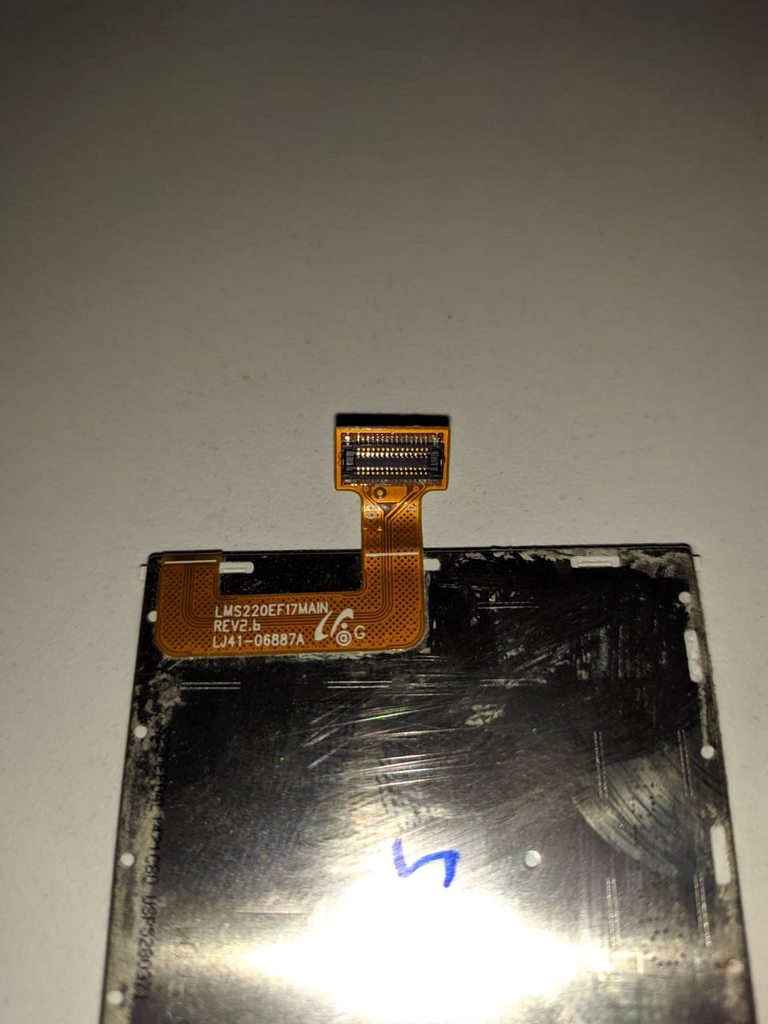
How can I use this old Samsung GT-B3210 display on an Arduino?
pine bramble
Basically you'd build a peripheral with its own memory, and send it data.
As an example, you could send ASCII to a Raspberry Pi, which renders it in an xterm in a specific font, size and color, via its HDMI port.
Some microcontrollers have multi-pin interfaces that might support some kind of a display, directly, I think.
The 'Arduino-ness' of such a setup is the SPI interface, shown in the above device's pinout, here:
https://learn.adafruit.com/ra8875-touch-display-driver-board/pinouts#spi-logic-pins-3019682-5
So generally, you find a driver chip like the above, then shop for a display that works with it.
Then write a library for it. ;)
unkempt lagoon
So a lot of trouble to make it work then
That's out of my league, but thanks for the answer
 woven wedge
I'm using an arduino micro in place of a teensy. I was provided a script which uses key modifiers like "KEY_UP", "KEY_DOWN", etc. However it looks like a library specific to teensyduino. I've tried searching for where these are defined in teensyduino but "KEY_UP" as an example didn't return anything. I'm using just plain Arduino IDE 1.8.10 on Linux
wraith current
@woven wedge how are you reading the keyboard ?
It's probably in the board definition somewhere but this might help https://www.pjrc.com/teensy/td_keyboard.html
woven wedge
A python script
I searched up that table and got https://www.appgamekit.com/documentation/guides/scancodes.htm I'll try it out
Actually this one's different
 kind flare
Error for setting up feather sense "Target not in DFU mode". ANY HELP with this???
woven wedge
Discussion on my library issue: https://forum.pjrc.com/threads/56808-Keyboard-HID-codes-not-working
Morning all,
This is a question tied to the same project I posted earlier here:
https://forum.pjrc.com/threads/56715-Simultaneous-USB-Host-and-Device-mode
and just so you know I have done research on this topic before asking for help, here's a post that asked a question...
wraith current
@kind flare Arduino ? have you tried bootloader update ? https://learn.adafruit.com/bluefruit-nrf52-feather-learning-guide/updating-the-bootloader

Adafruit Learning System
Get started now with our most powerful Bluefruit board yet!
kind flare
@wraith current yes I’ve burned the bootloader but the green light on the feather goes on and I get the same error message.
sinful estuary
You can change the address of the HT16K33
Ohhh how do I do that? I was unable to find it in the learn.adafruit.com page for the thing
pine bramble
@pine bramble Hold down the reset button on the Arduino the whole time, then release it after you press the Upload button.
@lone ferry wow it works! thx*10000!!!!!
lone ferry
You're not the first person to run into this problem, haha.
 abstract night
Hey guys I've got a Circuit Playground Bluefruit and am trying out some real basic Arduino coding for my class, I'm trying to use the two buttons as keyboard inputs however errors are called every time saying HID.h cannot be found
The code works, its directly from my tutors. It just seems to be that my Bluefruit chip isn't behaving like the regular Circuit Playgrounds. Is there something extra I need for these basic arduino libraries to work?
All the online help I've found only talk about circuitpython, but we aren't using that for the course
pine bramble
@woven wedge I use ag which is called the silver searcher.
I think it's found on github; Debian may've had a prebuilt copy.
Then just
$ ag KEY_UP
works a lot like a recursive grep.
Don't know windows terminology for that; Mac OS probably has grep or egrep.
@abstract night The method used to read the pushbuttons may be different.
HID.h implies HID which is a USB thing ("Human Interface Device" or somesuch).
That's a more advanced means of generating keystrokes or mouse swipes. Arduino generates these but does not read from them.
Either the Adafruit guide for the target board (the thing you're programming) or the instructor's instructions (haha) contain the name of a missing library, would be my guess here.
Also, post the entire error message block from the Arduino IDE, to a pastebin type of website, and link that here. All of it.
Control A followed by Control C may copy all that text. It's in the lower half of the IDE window.
abstract night
Here's the error message
Arduino: 1.8.13 (Windows 10), Board: "Adafruit Circuit Playground Bluefruit, 0.3.2 SoftDevice s140 6.1.1, Level 0 (Release)"
In file included from C:\Users\Jadyn\Desktop\Deco2300\Arduino\Hello_Keyboard\Hello_Keyboard.ino:1:
C:\Program Files (x86)\Arduino\libraries\Keyboard\src/Keyboard.h:25:10: fatal error: HID.h: No such file or directory
25 | #include "HID.h"
| ^~~~~~~
compilation terminated.
exit status 1
Error compiling for board Adafruit Circuit Playground Bluefruit.
This report would have more information with
"Show verbose output during compilation"
option enabled in File -> Preferences.
pine bramble
Right, turn on all Warnings.
There's a forward slash in that path. ;)
C:\Program Files (x86)\Arduino\libraries\Keyboard\src/Keyboard.h:25:10: fatal error: HID.h: No such file or directory
Sorry how do I turn on all warnings?
Yea I noticed that but its not anywhere in the sketch
pine bramble
In the upper left side of the Arduino IDE there's menus.
Keyboard seems to be the library used.
abstract night
Thats the full error message
Yea Keyboard.h is what Ive used as the include statement
I have no idea where the backwards slash is coming from...
pine bramble
I'm looking at that now. Thanks, that's what's needed.
It helped me to understand the context, but it still looks like there's at least one library you don't have installed.
The hello keyboard .cpp file has #include type statements at the top of the file, maybe?
I'm afk for 15 minutes (8:19 EDT). EDIT: back. ;)
abstract night
😄 So I got not idea where the .cpp files are coming from.. I can't find them anywhere
the .ino only has #include <Keyboard.h>
pine bramble
Well in Linux, /home/myname/Arduino/libraries
that has the path for the libs. You install them and they reside there.
abstract night
does C:\Program Files (x86)\Arduino\libraries seem right?
Bunch of folders that do look like libraries
pine bramble
I don't know about the x86 part but the rest of it looks promising.
abstract night
C:\Program Files (x86)\Arduino\libraries\Keyboard\src this contains the Keyboard.h file
pine bramble
I haven't used Windows in many years so I'm not familiar with common tasks using it, such as locating a specific file on the disk, by it's name.
There may be an HID.h file in the same directory.
Either you already have the file and aren't referencing it, or you don't have the file, and need to install the library that holds it.
Maybe post the project's .ino file on pastebin type of web site as well.
Or you can upload it the way you did with message.txt
abstract night
Yea alright, Its just a simple sample they gave us
This is whats in the library file
pine bramble
Yeah.
So Keyboard.cpp seems to point to HID.h I think.
You're calling Keyboard.h in that include at the top of hello..ino
Maybe it's the wrong Keyboard.h version.
abstract night
Am I missing some HID library?
pine bramble
Upload Keyboard.cpp here
abstract night
pine bramble
thankx
edit your hello to say something like:
#undef _USING_HID
The leading underscore may be wrong.
Then exit the Arduino IDE, start it again, and try to compile.
If you actually need to use something from the HID stuff, you'll know it soon enough. ;)
abstract night
Add that line anywhere?
pine bramble
Before you #include the keyboard.h first undef that _USING_HID thing
So just above it.
That should tell the keyboard driver you aren't using HID.
(assuming you are not)
If this works for you, it still may not be the entirely satisfactory answer.
Really depends on the intent the instructor had. ;)
abstract night
Still runs with the same error after restarting with the line added
pine bramble
The word sketch in white at the bottom of the compilation is your clue that it compiled correctly.
Okay so ignore all I said about #undef then.
The file seems peppered with references to USB and HID. ;)
The good news: the file has Arduino LLC in the top.
2015 Peter Barrett.
So it's probably already installed somewhere.
Wild guess: try
#include <HID.h>
Try both positions (above, and below, the include for Keyboard.h)
Just so you know: your .ino file does NOT use HID at all, from what I can see.
OH. Just comment out the include for Keyboard.h
See what that brings.
Two forward slashes together (no space) starts a comment.
abstract night
ok so the include HID couldnt find anything else
and commenting that out gives
'Keyboard' not found. Does your sketch include the line '#include <Keyboard.h>'?
pine bramble
Oh wait a minute you can't do that either as it's got keyboard. (keyboard dot anything).
Sorry my bad.
abstract night
no worries dude Im just hella confused about this
pine bramble
Keyboard.begin();
we have to satisfy that one, so Keyboard.h is required for sure.
Maybe not the version you have, but some version.
That's too big an error to dismiss as an instructor's trick, or a typo.
In real programming, I make the kinds of mistakes I'm making here all the time, but I'm not pressed to explain them to another person, so they aren't avoided (no need to; I learn from mistakes).
The idea is to make your mistakes quickly. ;)
abstract night
Yea I'm sure making a lot with this new tech this course threw at me 😅
so maybe update some libraries?
pine bramble
OKAY.
You are making keyboard characters for HID with the program.
You are using the target as a surfeit keyboard to control something like a personal computer.
So the Adafruit examples will hold or at least be helpful.
We can probably find something on learn.adafruit.com.
Probably this, but I just found it in google just now:
https://learn.adafruit.com/ble-hid-keyboard-buttons-with-circuitpython
oops that's circuitpython. ;)
pine bramble
This one looks more to the point:
https://learn.adafruit.com/mouse-and-keyboard-control-using-tinyusb-and-ble/understanding-arduino-mouse-keyboard-classes
Here is their link to the Arduino.cc site's writeup:
https://www.arduino.cc/reference/en/language/functions/usb/keyboard/
I'm still seeing Keyboard.h as the single point of entry.
and it *should* already be there.
So I'm confused as to why there's an error at all.
abstract night
I just had a read through and it all makes sense. Still super confused why mine is throwing errors
Do you have any clue about that reversed / from the error?
pine bramble
The more I look at it the more I rule out any instructor 'tricks' to 'gotcha' on purpose for a lesson.
Yeah that reversed slash seems wrong to me.
I don't know if it can be overlooked or if it's endemic.
Still it should have been taken care of long ago by someone who wrote this stuff.
There's a dim possibility that LINE ENDINGS are a factor.
Linux, Mac OS and Windows each use different line endings.
So when you press ENTER a short code is stored in that text file.
It's considered legal text, even though it is essentially a binary code.
That's how far down the rabbit hole we're going, here. ;)
Obviously 'reinstall the entire Arduino IDE' is the low hanging fruit, but that just seems extreme to me.
abstract night
drowning in the depths on the intro lesson suuucks
so If i tell the IDE the board is just the Playground Circuit it compiles no errors, cant upload though
pine bramble
My guesses are:
a) the necessary Keyboard.h was installed with the Arduino IDE
b) your instructor provided good and complete code, leaving
c) not sure just what's causing the error.
Yeah, so perhaps your choice of targets in the IDE is just plain wrong.
Is this an Adafruit board?
abstract night
yea adafruit playground circuit bluefruit
pine bramble
Do you have a product number for that? Like, 3333 is the CPX.
It's in the URL for the product's page.
The stuff I saw earlier indicated it was a recent NRF based board.
(NRF52 maybe)
pine bramble
-DARDUINO_NRF52840_CIRCUITPLAY -DARDUINO_ARCH_NRF52
abstract night
from the description
pine bramble
okay 4333 thanks
This is the Guide:
https://learn.adafruit.com/adafruit-circuit-playground-bluefruit
It'll probably have a Arduino IDE setup section.
abstract night
yep Ive followed that extensively
pine bramble
Reinstall this:
It's the BSP (board support package) for Adafruit NRF52
Its been around but they update all the time.
Select the correct variant as per this image (which is for another target in the same family):
Adafruit Circuit Playground Bluefruit
I'm just following this:
https://learn.adafruit.com/adafruit-circuit-playground-bluefruit/arduino-support-setup
abstract night
so remove the package and just redownload the latest?
pine bramble
Ignore the manual git stuff and the stuff about updating the bootloader.
Yes that's what I do. I remove it then install it.
It grabs the files off the internet and installs it for you.
Removing it first makes sure it does that without errors (ordinarily).
You can even downgrade it one level (or to any previous version) if you have trouble remembering what it is. ;)
Then upgrade to current.
That's kind of a bookmark as it were. ;)
This is a Hail Mary pass but sometimes it works.
pine bramble
Always exit the Arduno IDE.
Never reboot the computer itself.
soft use of 'always' and 'never' as that'd be absurd. ;)
abstract night
😁 ofc
pine bramble
Exiting the Arduino IDE just makes things a lot more standard. When it's truly necessary is a matter of experience. Often it's not necessary.
Control R should recompile the sketch.
Faster than using the menus and does the exact same thing.
abstract night
sweet
pine bramble
You can resize the lower half of the window to see more error messages.
abstract night
bad news though still same error
pine bramble
Yeah it's a little weird.
I'm not sure what's going on but it's probably simple.
Try a new empty sketch.
See if it compiles cleanly. That will validate the BSP for this target board.
Don't upload it though.
pine bramble
If that works, just
#include <Keyboard.h>
at the top of the otherwise empty sketch.
Empty here means
void setup() {
}

void loop () {
}
The red lines are expected. ;)
abstract night
ok sweet
pine bramble
Yeah it takes a while to figure out the red lines; they are warnings.
abstract night
the path "Keyboard\src/Keyboard.h" is still whats standing out to me
pine bramble
Try rolling BACK the NRF 52 from Adafruit.
This could be a typo that got approved for release.
pine bramble
happens.
That board's been on the market for more than 6 months iirc.
So there should be an earlier version that still has it supported.
The NRF52 board support goes way back, to earliest boards from Adafruit with that chip family.
abstract night
guess Ill just go back one at a time then and hope it eventually works
shame its one of the lengthiest installs...
pine bramble
0.20.5 and 0.20.1 are recent.
0.21.0 is the latest.
There's also the dim possibility that you also need, in addition to Adafruit NRF52 support .. Arduino NRF52 support.
Sometimes they leverage the Arduino version as well.
This happens with SAMD support for example.
abstract night
hmmm ill have a look
pine bramble
Usually, in the very latest Arduino IDE, it'll ask for dependencies for libraries, but I don't know about BSP's.
The bright side: this is a watered-down form of regular C and C++ programming skills. 'solving dependencies and missing libraries' is something every working C or C++ programmer faces.
It's good for you .. like cod liver oil. ;)
abstract night
a great lesson then 😩
pine bramble
Well it's a fact-of-life kind of thing. An obstacle most cannot avoid, and still get what they're after.
The reasonable man adapts himself to the world; the unreasonable one persists in trying to adapt the world to himself.
Therefore all progress depends on the unreasonable man.
-- George Bernard Shaw
me: that's very he/him of him. ;)
abstract night
haha I like that quote
pine bramble
Yeah I've spent a life trying to decide what it means in my case. I think anyone observing me would say 'that is a person who tries to adapt the world to himself' rather than the other way.
So like it or not I'm in the second category. Unreasonable. ;)
I think it's a choose-your-battles thing.
abstract night
I would love to just adapt myself out of this situation... I've gone back to 0.15 with no luck
should I keep trying?
This is the worst way to start a procrastinated project 😭
pine bramble
lol
I would drink two glasses of water.
I just had the one and probably need another.
The insights seem to be in the tap water. ;)
abstract night
Haha yea I definitely need some brain lube
pine bramble
You can try it on a second computer. You can get a friend to do it on their computer.
when rational approaches fail, sometimes magical thinking causes physical processes to occur (by your own actions).
abstract night
hmm I can install it all on my laptop, dont wanna have to move my entire project over there though if it works
I guess If it works over there I should reinstall everything arduino here?
oh god thats so many drivers...
pine bramble
I'm the friend. Doesn't compile here, either.
abstract night
Oh
pine bramble
Just by including Keyboard.h
abstract night
interesting...
pine bramble
so it's borked.
pine bramble
okay so the Keyboard.h uses quotes:
that's wrong, probably.
That would usually mean that same directory has HID.h in it. I think.
Let me see how many hits for HID.h there are in that tree.
zero. ;)
abstract night
Thanks man 🙂 means a lot youre helping out so much
pine bramble
I know it. You're welcome.
If I wasn't enjoying it I'd just make an excuse and leave. ;) lol
pine bramble
./hardware/arduino/avr/libraries/HID/src/HID.cpp
./hardware/arduino/avr/libraries/HID/src/HID.h
You could try making a copy in your local directory and editing it there.
Use the quotes to include it instead of the factory version. See if that works.
abstract night
ah shame it wont let me override
pine bramble
No it just doesn't exist. Tried it.
So that's an AVR lib, I think. Or an installed lib you and I do not yet have.
Or a mistake in the IDE distribution (unlikely).
Sometimes you go to github.com and look for an 'issue' filed against a library.
This is messed up, I think.
abstract night
oh ok
pine bramble
Let's assume you need a library that has the HID name in it.
pine bramble
There's HID Buttons by David Madison for example.
abstract night
yea Ive got that and HID-project
pine bramble
Really though somewhere on Adafruit's 'learn' server they should say exactly what's needed.
pine bramble
I might have it.
TinyUSB is definitely up-and-coming; wasn't used as much just a year ago or two years ago.
abstract night
what is tinyusb even?
pine bramble
~/Arduino/libraries$ ls -1 | cat
Adafruit_NeoPixel
Adafruit_SPIFlash
BLE52_Mouse_and_Keyboard
readme.txt
SdFat_-_Adafruit_Fork
Standard USB is different; tinyUSB is a new thing. ;)
Adafruit has migrated onto tinyUSB I think.
Presumably, it's tiny.
That didn't work - the BLE52_Mouse_and_Keyboard presumably needs its own reference, so the standard Keyboard.h won't work there.
trying
BLE52_Mouse_and_Keyboard.h
instead
abstract night
I included the BLE without Keyboard.h and although it took a long time to compile it finished
I think?
a few red lines but if thats ok I guess i can try uploading it?
pine bramble
No I got an error here. But if you saw sketch and a file size in white, it's probably good for an upload.
pine bramble
Um haha yeah it could.
The way it fries it (not really frying) is makes it difficult to upload to a second time.
Usually a single or double-press of the RESET button addresses that.
Apparently in Linux I need adafruit-nrfutil present for something (saw a dfu ref).
abstract night
didnt fry it but it isnt giving me the A and D output im after
should I get that or just try debugging from here?
pine bramble
Yeah, but it does compile and upload.
You can use Serial.println("hello there"); type debugs and look in SerialMonitor, if that's supported.
I got a phone call (there's my excuse). ;)
abstract night
Haha alright thanks man have a good one 🙂
pine bramble
If you're on linux, you can just create a fake binary (an executable script) that is named
adafruit-nrfutil
which is somewhere in your $PATH .. that will allow the compile to continue, if you don't have this already.
Seems to pack up the results of the compile for uploading to the target board:
adafruit-nrfutil dfu genpkg --dev-type 0x0052 --sd-req 0x00B6 --application /tmp/arduino_build_123456/this.ino.hex /tmp/arduino_build_123456/this.ino.zip
 merry bramble
Hello everyone, I'm not sure if this is the correct server to ask for help, but I have an ESP32 that I'm trying to program using Arduino IDE and I can't seem to get it to work.
I keep getting error messages saying "could not open port 'COM3'". I also cannot change the port number in the software.
I tried installing CP210x USB to UART driver, trying different PC ports but I'm running out of ideas
pine bramble
Yeah.
CP2104 is a great chip. I use it all the time.
There's means to troubleshoot to find the device.
Basically you open something like the old Device Manager in Windows, and plug in the device, and see what pops up.
merry bramble
I didn't really see the device in my device manager but I could try this method also.
Yeah, there's no changes in the device manager when I plug/unplug it from my PC.
The only thing that comes to my mind is trying a different cable which I do not have.
pine bramble
Well CP210x is dead generic at this point, so I'd expect Windows to already have the driver installed.
Oh yeah some cables are junk.
You may find a way to borrow one for an hour.
merry bramble
I do use that cable to recharge my headphones, though, so I don't think there's anything wrong with the cable.
pine bramble
When I was in hospital a nurse just gave me hers.
There are cables that are only good for power, but not for communication.
merry bramble
Good point, I might have to buy a new one on Monday.
pine bramble
I cut them in half with scissors, immediately, when I discover a cable that does not pass USB data.
That's worse than getting a fly in your soup, in a restaurant.
pulsar junco
at least the fly is protein
pulsar junco
that's too much cholesterol for me
pine bramble
hehe but you considered it, first. lol
north stream
I keep the power-only ones for use with untrusted chargers, but mark them clearly. If you don't have another cable, do you have another device you could try it with?
merry bramble
I unfortunately don't.
pine bramble
I bet ten bux you also have a good cable tagging system, @north stream ;)
merry bramble
And is there a way for me to find out if the cable will be good enough for this application? Like in the product details or something.
If you know what I'm saying.
pine bramble
You can test that cable any way you like. For example, hook it to an Amazon Kindle and see if you can read the Kindle on the Desktop PC (look at files stored on Kindle).
If it's passing data it'll be obvious.
If it is power only I'd expect the advert to say so.
north stream
I play with enough cables that I actually bought a cable tester, but that's overkill for most folks. My tagging system is re-using bread tags (picture swiped from the 'net).
pine bramble
They want to sell you things, so they should give you selling points so that you will do business with them.
@north stream Then I think I owe you at least $5 because I thought of a professional tagging system. I like the work-around better. ;)
merry bramble
Alright, thanks a lot for the help, guys.
 main olive
i have a servo motor hooked up to my arduino. Everything should work, but it dosent. is it the code or something else? code:```cpp
#include <Servo.h>
Servo testservo;
uint32_t next;
void setup()
{
// the 1000 & 2000 set the pulse width
// mix & max limits, in microseconds.
// Be careful with shorter or longer pulses.
testservo.attach(9, 1000, 2000);
next = millis() + 500;
}
void loop()
{
static bool rising = true;
if(millis() > next)
{
if(rising)
{
testservo.write(180);
rising = false;
}
else
{
testservo.write(0);
rising = true;
}
// repeat again in 3 seconds.
next += 3000;
}
}
Try moving the declaration for rising outside of loop (put it up by next)
main olive
what do you mean by that? If i put rising = false up there that wont work
north stream
Move the static bool rising = true; line up by the uint32_t next; line.
pine bramble
Also, always initialize when you declare.
north stream
Not required, really, C has rules for initializing variables.
pine bramble
uint32_t next = 0;
do need you need a driver to control a servo? The code kinda works. It does then it doesent
north stream
What the code is doing under the hood is configuring a timer to produce a pulse width modulated (PWM) signal which the servo understands. Once it's set up, the timer takes care of it for you.
The signal level produced by the Arduino is fine as a servo input, so you don't need a hardware buffer.
obtuse spruce
rising is fine where it is - it is static. no need to initialize next - the logic is clear in this case for next...
obtuse spruce
My 35+ years of C++ professional development says otherwise... but in the end - this has nothing to do with the OP's issue.
pine bramble
;)
pulsar junco
Do you not need to initialize it because it is set to a non garbage value before it's ever used?
obtuse spruce
No - in this case, I wouldn't flag the non-initialization in review because it is clear from the code that it absolutely initialized to a value before it is used. AND because it is initialized using a time value, the initialization to 0 introduces another case to think about... which needn't be thought about because it is never used (due to initialization in setup). But really, it isn't a big deal - in this case - either way.
The code looks fine to me.
@main olive - I suggest adding this after the attach in setup():
   while (!testservo.attached()) {
     Serial.println("waiting for attachment...");
     delay(100);
   }
The way I read it, every time loop() gets called, rising will get set to true (static or not). In C, static normally reflects variable scope, not volatility.
In my code, I normally make global variables static (unless I'm referencing them from elsewhere), as it helps the build process save bytes.
obtuse spruce
No - that isn't what static inside a function means.
It means that it is initialized just once, the first time that function is called... but it retains the value from call to call. It is essentially a global variable that can only be used inside the function.
static at file scope means only visible within this file. It can be tricky to use correctly in a header file BTW.
(aside: static at file scope will not change the size of the executable nor it's memory foot print. Only the size of the intermediate .o files)
@main olive - other thought - you didn't mention which board you are using ... are you certain that pin 9 supports PWM (and hence servos?)... not all GPIO pins support PWM and it varies by board.
 tranquil fable
Ummm . what happens to next += 3000 inside the infinite loop ?
main olive
@obtuse spruce in the serial monitor it says it is not attached, or well, waiting for attachment
ok im going down to the basics. This dosent work, but all the things ive read and seen say should. Is there a problem with this?```cpp
#include <Servo.h>
Servo motor;
void setup(){
motor.attach(9);
}
void loop(){
motor.write(0);
}
I think you may need to pause after motor.write()
Maybe just move that statement into setup() and leave loop() empty?
 gritty nest
Hello All, so I am experiencing this weird thing with the Adafruit BNO055, every time I powered up the BNO055, I needed to calibrate the magnetometer (which is expected), I was using a Arduino Mega to read in mag values and create a compass. Now that I moved the BNO055 to the Arduino Due, for some reason every time on power up the BNO055 mag calibration value is always ‘3’ (which is not what is expected, we should have to recalibrate at start up). I am receiving erroneous compass readings and its waayy off. I am not sure if I screwed something up or not. The BNO055 can handle both 3.3V & 5 V logic so switching between Mega2560(5V logic) & Due(3.3V logic) should hopefully not have been the issue. Please any suggestions are welcomed! Thanks!
north stream
I wonder if it's a driver initialization issue, a communication issue, a storage issue, or a power issue.
gritty nest
Communication seems to be fine as I am receiving readings, I have BNO055 SDA/SCL pins connected to Due’s respective pins and Dues RX1 Pinned to a Mega TX1 pin. I have the Mega and Due connected in a Master/Slave config. Mega sends Due commands to process and receive answers back to Mega. This all seems to be working correctly
In terms of power I connected both to a LiPo 12 V 9600 Mah battery
Power may be issue as I have two 12 V motors and a 5 V rtk gps also connected
Has this been experience before? In terms of power
Could you elaborate on driver init issue? i am not too sure what that is
Gps is also connected to due on RX2
north stream
I figure the driver has to initialize a bunch of stuff, such as whether the magnetometer has been calibrated. If something was off, it might think it was when it wasn't.
main olive
ok so, i also improved it with adding a delay at void start. Now it looks like this:```cpp
#include <Servo.h>
Servo motor;
void setup(){
motor.attach(8);
motor.write(0);
delay(2000);
}
void loop(){
motor.write(180);
delay(1500);
motor.write(0);
delay(1500);
}
just spent 20 minutes debugging a problem; turns out that implementation of function isWhitespace(c) is Adafruit's core doesn't match the documentation on Arduino website. Didn't occur to me that there is any room for different interpretations of something that simple. Arrrrrgh... 🤬
pulsar junco
are they considering something whitespace that you don't, or the opposite or something else? V curious
vivid rock
according to docs, \r, \n, and \f should be considered whitespace. In fact, the implementation only considers space and \t whitespace
vivid rock
yeah, a very mild upset
🤬
pulsar junco
I'm gonna finish my pizza to banish it
I suppose you can implement your own isReallyWhitespace()
vivid rock
turns out they actually have a function which implements exaclty what I need; it is called isSpace. Unsurprisingly, in docs on arduino website this function is supposed to do something else. I had to read the source to find out what is happening.
pulsar junco
mind linking source?
pulsar junco
I thought .h files weren't supposed to have the full function in them, just defs/predicates/whatever the right term is
also seems like a reasonable first issue for someone to fix, maybe add the issue?
vivid rock
they can. for one-line functions it is common to put them in .h
I opened an issue
vivid rock
I guess __GNUC__ is a macro defined by GNU C compiler (gcc) , so it is defined if the code is being complied by gcc
which, afaik, is what is normally used internally by Arduino IDE.
pulsar junco
weird that they don't define any functions if _ICCARM_
I guess this could be a "good first issue" or just update the documentation
obtuse spruce
Probably because the ICCARM compiler's standard headers already define them.
And - I bet - the definitions don't match exactly... cause that is very common with character class functions in various systems.
pulsar junco
aren't the defs in there the arduino specific versions of the C functions?
obtuse spruce
Notice that all these functions, in the header file, have inline - which is why they are in the header file. inline in a .cpp file only helps that one file.
The standard C functions are all like isspace and isgraph. They are well defined by the standard... but... alas... are tangled up in the locale system, so - er - may or may not mean what you think they mean if you are on a system with locales (Linux for example).
I can't say why Arduino choose to make a new set...
obtuse spruce
and yes - @vivid rock - there is a bug in that file --- it is this: The definitions of isWhitespace and isSpace are reversed.
also - no idea why that file uses the idiom
return (isxxxx(c) == 0 ? false : true);
that's just verbose for no reason:
return isxxxx(c) != 0;
or just:
return isxxxx(c);
are just as good, and frankly, more clear
Oh - it looks like it is the documentation is wrong. Or at least? My Arudino (non adafruit) core has them they same way Adafruit does
pulsar junco
If they swap the two to fix the bug, they would also need to update the docs to indicate that isSpace(c) gives tab or space right? RN it says space char only.
obtuse spruce
Looking at the core - I think the docs are wrong!
pulsar junco
well if they want it to match C, doesn't isspace(c) always check for \r,\n,\t,\f, and space?
but then they have the isWhiteSpace(c) fn which seems to want to be isspace(c)
it's sort of an update one or the other situation it seems, depends on what you want to be what
obtuse spruce
latest arduino cores on my system both match Adafruits: isSpace is implemented as isspace and isWhitespace is implemented as isblank
which makes - isSpace/isspace the one that has the vertical line characters -- and isWhitespace/isblank the ones that have just the space and tab.
If you're really worried about it being consistent... don't call the Wiring ones - call the C ones - they're well defined and won't change!
pulsar junco
that's what I was gonna ask, why not just use the built in C functions in the first place!
vivid rock
@obtuse spruce indeed it seems that the documentation needs to be fixed rather than the implementation.
How come no one ever noticed it before, i can't imagine
pulsar junco
history happening before our eyes!
vivid rock
bug report submitted.
 hybrid dragon
Hey can anyone tell me why the SPI display I have doesn't show anything when I run this?
void loop() {
  display.setCursor(0,0);
  Serial.println("Searching for Tegra");
  display.println("Hello!");
  display.display();
  delay(2000);
  display.clearDisplay();

}
Here's my setup function:
void setup() {
    Serial.begin(9600);
    display.begin(SSD1306_SWITCHCAPVCC, 0x3C);
    display.display();
    delay(3000);
    display.clearDisplay();
    display.display();

    delay(2000);

}
nevermind i fixed it
 dry salmon
how can I troubleshoot connection errors using Feather M0 WiFi? Wireshark shows that the WINC1500 disconnects after the TLS handshake, but there are no errors in the handshake, I've loaded the CA certificate to the WINC1500, and OpenSSL doesn't see any problems with the server certificate. WiFiSSLClient does not expose any error details
dry salmon
I'm getting socket error code -12, SOCK_ERR_CONN_ABORTED. The documentation says that the connection is closed by the peer, but Wireshark says that is not true.
yes, although maybe I should do it again
dry salmon
I did have a problem with RabbitMQ sending incomplete certificate chains…
stuck coral
If you have issues with RabbitMQ and SSL, try putting a proxy application like nginx in front of it. In my RabbitMQ deployment, a application load balancer is in front of the rabbitMQ MQTT listener and provides the TLS layer as well as adds a WAF
dry salmon
that was it. I uploaded the certificates again now that socat does the tls for rabbitmq and now I can connect
I don't think the certificate uploader gave me an error before. I wonder what it uploaded
stuck coral
Fantastic, if you do any large scale or professional deployments in the future give my suggestion a try 😜
dry salmon
it's just a server for my house
I think now I just need to redo all the accounts. I saw somebody had solved a problem with RabbitMQ certificate chains by upgrading to a newer version, which didn't work for me, but in the process I accidentally wiped the configuration
stuck coral
Ah, lol. Note that you can save and reload any config as a JSON file though you probably know that. And for connected embedded devices, the HTTP auth is fantastic if you are provisioning many devices
dry salmon
it turns out I did not delete the configuration. The new Helm Chart for RabbitMQ uses a different base directory, so my configuration was just in the wrong place
stuck coral
Oh thats good, making new config files is a pain. Having to reenter everything in the interface is even worse
north stream
Hi guys, I have an Elegoo Smart Car and I want to try to modify its speed. I tried PWM with no luck so decided to do my own way similar to PWM (forward-delay-stop-delay loop). I got it working at times then I noticed a weird behavior. If I push the remote button that increases the delay time variable it keeps changing non-stop instead of changing one step. The infrared module light blinks only once so it doesn't seem to be a remote malfunction. This is my code that I am using for it https://hatebin.com/wqzhmskjmm. I hope anyone could help me fix that.
north stream
You might want to clear results.value after acting on it, otherwise the loop will keep re-using the last received value.
yes, it worked.
i used results.value = 0; in the end of the loop
thank u so much :)\
🙂
woven wedge
I'm running an arduino micro but it looks like my target script was designed for a teensy. I'm thinking that rather than rewriting the definitions for my arduino it would be easier to just buy a teensy. Unless the fix is super trivial like including all of the teensy libraries in my project or there's a library that does this.
woven wedge
I guess this is a software issue since the arduino and teensy keyboard libraries exist independently. In that case I'm looking for a completed solution for grabbing key presses and sending via UART to a listening micro
Just the software that goes on the micro since I have the UART part
north stream
If I understand correctly, the keyboard libraries allow you to configure the micro's USB interface as a keyboard HID device, so you can emulate a USB keyboard, and this is sort of the opposite of what you're describing, which seems like receiving keyboard data via USB and handing it off serially via a UART?
elder hare
dont know if anyone remembers the ESP32 i got sent where there was a extra resistor soldered to the board from a via to the reset button xD well i removed that one and i uplaoded some code! and well.. it posts that wifi is up and running BUT i can't connect to it with socket for some reason :S there is no contact what so ever