#help-with-arduino
1 messages · Page 76 of 1
 stuck coral
 shadow wharf
yea I right-clicked the include to get to the source and it opened up a file that was located in a folder called teensyduino (which I am using)
by all that I can see it is the file it's using for compiling
stuck coral
If you have a #error in the code, it is not using the file to compile
As long as the #error is defined, if you press clean and it still compiles, that is just fact
Delete the .build folder as well just to make sure
shadow wharf
putting the #error before the #ifndef guard the compile failed. But some other file that I have no idea about is blocking it
stuck coral
There is no "blocking" I dont understand that term in this contex
shadow wharf
#include guard, sometimes called a macro guard, header guard or file guard
maybe better terms for it
stuck coral
That isnt really blocking as much as there is another file that has already fulfilled the definition
shadow wharf
right, and I don't know what file that would be
but I guess I'll find it. I managed to do what I wanted which is sufficient for now. Again thanks for the assistance, this has been bugging me for hours
 pine bramble
It's annoying to trace, but I think I was able to get a pretty good idea of what the C preprocessor output was, in the build directory, for a project where it was helpful to know that.
 north stream
I'll generally capture the compile command and re-run it with the -c option changed to -I or -E to get the preprocessor output.
 thorny kindle
hello! I have a Duino kit with arduino nano bored in it and I don't know how to put code in in Arduino IDE
Can anyone help me with this?
north stream
The Nano should be straightforward enough, you'd need the Arduino IDE, a USB cable and (maybe) a driver for the serial chip on the Nano.
thorny kindle
I think I need money for the driver
north stream
Most of the Nanos use one of five common chips, all of which have free drivers available. The first step is to figure out which chip yours has.
thorny kindle
How can I find out?
north stream
You can do that by either examining the chip itself (probably with a magnifier), or plugging it in to your computer and examining the USB devices to find out the vendor and product IDs.
thorny kindle
and how can I find the product ID?
north stream
Most operating systems have a way to show what's connected to USB (lsusb for Linux, System Report for MacOS, etc.)
thorny kindle
I have windows 10
thorny kindle
where on the bored has the product ID?
 torpid patio
hello, I'm stumped and could use some help, I'm trying to reassign a pin on an Arduino Mega to a servo shield pwm pin, but without using the library for it, because I'm trying to implement a easing function.
what's the code to call that pin instead of assigning it to a digital pin, like 9?
 cedar mountain
If I understand the question, you can't really do that, since the PWM outputs are not really "pins" from the Arduino's perspective, they're just abstract things which are controlled via I2C commands to the chip on the servo shield.
So you pretty much have to either go through the library or effectively implement your own library to do the same sort of thing.
torpid patio
ah ok
thanks
If I cant reassign the pin, then how do I tell the ServoEasing Library to use that instead of the digital pins? it has a way to use the PCA9685 boards but its examples only show it working through the digital pins
cedar mountain
It looks like you're supposed to initialize the ServoEasing library like ServoEasing Servo1(PCA9685_DEFAULT_ADDRESS, &Wire);to tell it to use the expander, and at that point the "pin numbers" you give it are the ones on the expander, not the native pins.
torpid patio
I tried that, but I get this error:
no matching function for call to 'ServoEasing::ServoEasing(int, TwoWire*)'
and I'm not sure how to resolve it
this error is happening straight in the PCA9685_Expander example
it's this line:
pine bramble
Hi guys if i want to connect my arduino to my xampp server do i need a ethernet shield + router? Ethernet shield + switch hub? or ethernet shield alone is enough? Do i need more drivers? or Apps?
I cant connect my arduino to my xampp server atm. Im using ethernet shield alone. I want to connect to my xampp server and try to send and get data from it.
 wintry berry
can someone show me how to work with this fonts on the 0.96" oled screen?
https://github.com/jdmorise/BMH-fonts/tree/master/bmh_fonts/bmh_char/Indie Flower Regular

GitHub
A library of free bitmap header fonts with character height from 24 to 64 pixels for use in monochrome LCD or OLED Displays - jdmorise/BMH-fonts
 bleak steppe
@pine bramble thanks you very much for all those forth interest links , this seems to be what I am looking for 👍 
 hallow torrent
guys if i was to make a game controller with a Mega, which library could i use? and if you have some example code that'll be very helpful! thanks in advance mates!
and i could easily change Bluetooth controllers code to work with USB?
 carmine jetty
Hi I joined a while ago and I could use a little bit of insight myself. I have one of those cheap arduino nanos with the CH340 chip. I ran into an error where I initially didn't think it was reading the board itself after trying to upload an example program for an OLED screen.
After much fooling around seeing if it was the port, the processor type, or the programmer type I came across an idea of uploading a program with just an empty void setup and void loop. Turns out it can upload, but for some reason cant read flash memory after a certain point when I instead use adafruits SSD1306 example sketch.
Error here:
avrdude: Device signature = 0x1e950f (probably m328p)

avrdude: reading input file "C:\Users\chico\AppData\Local\Temp\arduino_build_919980/ssd1306_128x64_i2c.ino.hex"

avrdude: writing flash (20958 bytes):


Writing | #############avrdude: loadaddr(): (b) protocol error, expect=0x14, resp=0xfc

##################################### | 100% 5.91s


avrdude: 20958 bytes of flash written

avrdude: verifying flash memory against C:\Users\chico\AppData\Local\Temp\arduino_build_919980/ssd1306_128x64_i2c.ino.hex:

avrdude: load data flash data from input file C:\Users\chico\AppData\Local\Temp\arduino_build_919980/ssd1306_128x64_i2c.ino.hex:

avrdude: input file C:\Users\chico\AppData\Local\Temp\arduino_build_919980/ssd1306_128x64_i2c.ino.hex contains 20958 bytes

avrdude: reading on-chip flash data:


Reading | ##########avrdude: stk500_recv(): programmer is not responding

avrdude: stk500_recv(): programmer is not responding

avr_read(): error reading address 0x0000

    read operation not supported for memory "flash"

avrdude: failed to read all of flash memory, rc=-2

the selected serial port avrdude: failed to read all of flash memory, rc=-2

 does not exist or your board is not connected

avrdude: stk500_recv(): programmer is not responding


avrdude done. Thank you.```if you need additional specs from the error message which is mainly about the nano board itself I will be more than willing to provide it
thorny kindle
Where on a arduino nano is the product ID
I have a picture of the bored if you need it
thorny kindle
RX light?
carmine jetty
Hold on. ill get you a picture
north stream
@thorny kindle Should be the chip closest to the USB connector
north stream
Hmm, that's a different layout than I'm used to. Are there any chips on the bottom?
north stream
Ah, that's a CH340 USB-serial chip. The drivers for that chip are available free from the chip manufacturer.
carmine jetty
yup as mentioned earlier
north stream
Sorry, confusing two different conversations
carmine jetty
my issue is that I can upload a small program, I had it set to the old bootloader for the atmega328, and had it as arduino as isp
and yeah sorry I got confused originally when he asked about product ID
thorny kindle
Well my camera is having a hard time focusing at the numbers
north stream
Can you read the numbers?
thorny kindle
No
north stream
That leaves trying to get the vendor and product IDs from the computer
thorny kindle
Ok so I turned on my flashlight and I saw it much better
Oh wait I have a different nano board than yours
It says I have a v3.0
carmine jetty
yeah madbodger was saying mine was different than he was used to. So you probably have a better board than I do. Im newer to the arduino boards than coding, but I get the concepts behind the boards. Just not what is happening in my case. btw I do have the driver installed for the ch340 already madbodger
north stream
Parappa was asking about getting a computer to communicate with the Nano, so we need to figure out which USB-serial chip it has, in order to install the correct driver for it.
carmine jetty
aaah that makes sense
north stream
Your problem is a different, and more subtle one. Usually these things work right or not at all, not fail partway through: that's unusual.
carmine jetty
@thorny kindle where did you purchase that board from? do you have a link to where it can be bought?
thorny kindle
I bought it from duinokit.com
carmine jetty

DuinoKit - Educational Electronics Learning Kits.
Arduino compatible NANO microprocessor as used in the DuinoKit Essentials and the DuinoKit Jr. This version uses the FTDI chip on the programmer circuit and it a replacement to the NANO shipped with the DuinoKits.
carmine jetty
on the original link that I sent in it said it used and FTDI chip. That is essentially what you might be looking for on the bottom by the USB and then it should have some number with it
north stream
Yes, it's probably worth installing the FTDI driver: that one's also free and available from the manufacturer.
thorny kindle
How do I download it?
carmine jetty
USB RS232 - FTDI designs and supplies USB semiconductor devices with Legacy support including royalty-free drivers. Application areas include USB RS232, ( USB Serial ), USB Parallel, USB Docking Stations, and upgrades of Legacy designs to USB.
this appears to be it
thorny kindle
oh wait I did it wrong
cedar mountain
@torpid patio It sounds like you may have a different version of the ServoEasing library installed than the one the example is written for.
torpid patio
the example came with the library
i only got access to the example when i installed the library
but if the example doesnt match the library, how do i edit the example to make it work?
cedar mountain
Hmmm, did you edit things when you were originally using the on-board pins, perhaps removing the USE_PCA9685_SERVO_EXPANDER define?
 wispy crater
pls help me in combining two arduino codes
thorny kindle
ok I download everything and I found a website to help me but I don't see the driver in the device manager
wispy crater
pls help me in combining two arduino codes
carmine jetty
which part of the device manager are you looking at parappa?
 vivid rock
@wispy crater can you provide a little more info?
carmine jetty
my nano is listed under the ports
wispy crater
https://pastebin.com/yHUbWbCd this pastebin post contains both programs
Pastebin
Pastebin.com is the number one paste tool since 2002. Pastebin is a website where you can store text online for a set period of time.
thorny kindle
Other devices
vivid rock
@wispy crater what kind of LCD screen do you have? is it I2C or not?
and what exactly do you wnat to achieve?
wispy crater
@vivid rock 1 code have 12c and other is normal
vivid rock
I saw it. SO my question is what kind of LCD screen you have in real life
not all LCD screens are I2C-capable
wispy crater
@vivid rock i have both
vivid rock
then I would use the I2C capable one, it makes life easier
wispy crater
not all LCD screens are I2C-capable
@vivid rock sorry
carmine jetty
@thorny kindle have you tried updating that driver from the device drivers menu?
vivid rock
but you still haven't responded what exactly you are trying to achieve
 gilded swift
Ahhhh the Faux Nanos
vivid rock
Fake News!
gilded swift
lol
wispy crater
then I would use the I2C capable one, it makes life easier
@vivid rock k
gilded swift
I have a faux nano nano that i used to program my less Faux Nano lol
Notice the beautiful after dark OshPark board and micro usb
carmine jetty
definitely a good color
wispy crater
but you still haven't responded what exactly you are trying to achieve
@vivid rock i want to make a vertical farm as my competition project so i want to add a farm statistics display and a automatic irrigator
gilded swift
And the luxurious FTDI usb interface on the bottom
vivid rock
can you be more specific? what sensors do you plan to use, what exact statistics the display shoudl show, etc?
gilded swift
Also, don’t worry about the bridge, it’s not intentional but it’s bridging two pins that are already connected to GND
wispy crater
can you be more specific? what sensors do you plan to use, what exact statistics the display shoudl show, etc?
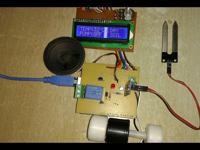
@vivid rock actually i am making this https://create.arduino.cc/projecthub/GilettaStefano/aws-arduino-weather-station-9e5a21?ref=search&ref_id=aws&offset=0

Arduino Project Hub
Very useful project made at school that detects some weather data. By GilettaStefano.
@vivid rock and this https://www.youtube.com/watch?v=KWts8QZKIJw&t=175s
PCB for 2$ (any colour) : www.jlcpcb.com
I will show you how to build and implement an automatic irrigation system which can sense the water content in the soil and automatically irrigate your garden. This system can be programmed for different crop requirements and seasonal ...
i want to combine both these
vivid rock
ok, let me take a look
wispy crater
@vivid rock but in the video i am not using the speaker and water pum i place of water pump i will put a buzzer
wispy crater
@vivid rock and if possibel try to add 2 dht11 and 2 lm35 more
vivid rock
i'll check
wispy crater
k
thorny kindle
I installed the driver and everything and it still won't show in device manager
thorny kindle
Yes I did twice
gilded swift
okay.. hmm
thorny kindle
should I restart my computer again
thorny kindle
i just restarted my computer and the driver is still not their
north stream
Usually the next step is to see if it enumerated the USB device, but I don't know how to do that on windows
thorny kindle
me either
gilded swift
same
Try reinstalling the driver
make sure the device isn't plugged in when you do it
carmine jetty
doesn't look like it
what is under the ports section instead of the the other devices section
even better yet too, you might be able to figure it out by just unplugging the USB device and seeing what devices stop showing
torpid patio
@cedar mountain I did not, i just opened the example, added the wire.h library, and compiled
cedar mountain
In that case you might need to explicitly define USE_PCA9685_SERVO_EXPANDER yourself before the library import. It's not immediately obvious to me that the example is set up to work out of the box.
Or maybe I have things exactly backwards... ``` * !!! Comment out line 40 "#define USE_PCA9685_SERVO_EXPANDER" in ServoEasing.h to make the expander example work !!!
- Otherwise you will see errors like: "PCA9685_Expander:44:46: error: 'Wire' was not declared in this scope"```
I'm losing track of all the nested defines in this code...
thorny kindle
so i tried to update the driver but it said it was already updated
 north stream
north stream
north stream
That appears to say you have a driver installed that should work and have it appear as a serial port, which is what you want
thorny kindle
So I should uninstall the driver and start over?
north stream
That depends. Does it show up as a serial port now?
I do laugh at windows when it says the "best" driver is installed, then goes on to admit there may be "better" ones.
thorny kindle
it says USB Serial Port (COM3)
north stream
Then you should be able to select that as a port in the Arduino IDE to talk to your board.
north stream
Go to the "port" menu and select that port?
thorny kindle
and I press the magnifying glass?
north stream
I'm not sure what you're looking at.
thorny kindle
it says serial monitor
north stream
I don't think you need the serial monitor yet.
thorny kindle
oh ok
carmine jetty
The serial moniter would be used to read the output data. First you would need to see if you can successfully upload your sketch to your board
So when you go to tools and serial port while your board is plugged in you should have an option to pick COM3
After which you then attempt to upload your program
pine bramble
The Serial Monitor is just a built in serial communications program, like minicom, seyon, Procomm, Telix, Hyperterm, and Putty.
It's job is to accept your keystrokes and send them along to some other computer, via modem, RS-232, USART, USB and such.
And to relay the responses (in ASCII text) back to you.
Unlike many of those programs, the Serial Monitor uses a 'split screen' concept, and even more unusually, puts the part where you type at the top, instead of at the bottom of the Serial Monitor window.
thorny kindle
I went to basics and did blink. It seemed like it worked.
north stream
Ah, so now your computer can talk to your board!
thorny kindle
Yes
pine bramble
How can i set up any microcontroller (arduino) to talk to my Python program running on my laptop via USB
?
stuck coral
By using serial ports
pine bramble
i meant is there any library of python to do that?
stuck coral
Im not a python programmer but I think there is a library called pyserial
pine bramble
for example if i want to write data to turn on an led to arduino and also want to recieve the temperature in my python program, How do i do that?
yeah i tried (pyserial) it it's just a mess, it throws out a lot of gibberish (or may be im not good at using it )
stuck coral
Program the arduino to receive bytes from the serial port, and when you get a specific byte turn the LED on, and when you sample temp data, send it over the serial port, there are a few ways to do that, most people will stringify it and send it followed by a newline. And pyserial works fine, I think you are misunderstanding some part of implementation
pine bramble
Hmm i should learn more about pyserial, Thanks
One more Question, is there any alternative of pyserial? any one?
stuck coral
There probably is, but use pyserial
pine bramble
O okay
 stark bridge
I use pyserial all the time. It works perfectly.
pine bramble
Yeah it some times works perfect but after 5-6 iterations it start to throw out random letters and that was when i tried to make an opencv Robot
stark bridge
That's not a problem in pyserial. That's a problem in your code or your circuit.
stuck coral
Well pyserial is used in commercial applications and has been around being worked on almost as long as python itself, so I would be dumbfounded if the library was the issue
And the library isnt even the thing receiving the data, it just helps you do that in any OS you're executing on
pine bramble
hmm, i really need to learn more about it, i think then my code was lacking at data handling (striping out the unneccessary data or may be delays of some sort idk)
Thanks guys
stark bridge
I can't think of any reason you'd want to use delays in serial code.
I recommend learning the details of serial (UART) communication.
pine bramble
i did actually used delays cause there was a specific movement i wanted to do with the motors so it required delays in the arduino sketch
stark bridge
The problem is if any serial data being transmitted during the delay, it could be lost or get out of sync. Without seeing the code it's impossible to say more. But in general you want to avoid using delay() and instead use millis() in Arduino code. Or use a timer with or without interrupts when writing bare-metal code.
pine bramble
Hmm, i didn't wrote the sketch of the current project that im working on so i can't really show You the code but i will keep in mind these tips while writing it. and there is no reason to go back to that Opencv project cause i just abandoned it 3 months ago
pine bramble
It's very simple: you have an expectation that wasn't met.
Serial communications are nothing at all like error-free protocols.
It was real obvious when the (telephone) line took a strike, when you were on a dial-up modem link.
We called that LINE NOYS because it annoys.
Even after you factor out those kinds of errors, you are far from done.
Right now I'm working on the Locus Engineering E1115F PS/2 keyboard, to USART, dongle.
The normal alpha keys produce one character (rather than a series of 'key stroke codes') when typed on the PS/2 keyboard.
As 'expected'.
But that wasn't quite the way to describe what happens when a non-alpha key is pressed.
Including some funny business.
pyserial will likely turn out to be the best thing going, for where you're using it. Don't change it. What are you going to change it, to? ;)
You want to know a few things, like is one utterance of a different length as another utterance.
Or is it of the same length?
You want to know if more than 7 bits are used; you want to know if ASCII figures into it, or not.
You want to know if you are filtering out 'garbage' (unprintable characters in the current context).
You want to know if there are unhandled cases.
Baud rate sync issues. Auto-baud detection.
I would write a Forth server on one or both ends of the connection, communicating via USART.
In this case, python, not Forth, on the host/desktop PC side.
Could write the Arduino based server in Arduino IDE (C++) or in CircuitPython.
You'll be parsing, for sure. ;)
I like parsing Forth, because each utterance is separated only by a space, and that utterance can only be one of two entities: an integer (spelled out using the ASCII codes for each of its digits) or it can be 'the other thing' which is (essentially) the name of a function to execute.
(Also spelled out in ASCII).
 oak locust
Hi, Im new to all of this, so my problem could be stupid. I have the Circuit PG express. I have uploaded some code, but now it has despaired form the port. I cant seem to get it back. I have tried restarting arduino, restarting the CPE, disconnecting the USB. Nothing helps.
north stream
It can emulate different USB devices, depending on the settings. Does it enumerate as a USB device at all?
pine bramble
@oak locust Double-check the target in Arduino IDE.
If you uploaded for Circuit Playground (non-express) that may be enough to confuse the target.
north stream
There are a few reasons something might not enumerate on USB any more, but the most common is a poor connection.
oak locust
@oak locust Double-check the target in Arduino IDE.
@pine bramble The board is correct
It reappeared now when i connected the usb to a new port - but that does not explain why i was able to upload code before?
There are a few reasons something might not enumerate on USB any more, but the most common is a poor connection.
@north stream This worked out!
pine bramble
/dev/ttyACM0
/dev/ttyACM1
when one doesn't work try the other.
Takes quite a few recoveries from this to notice the fastest way back to regular operation.
oak locust
thanks Nis!
pine bramble
;)
Used to drive me batty, before I figured it out. ;)
Basically the operating system is holding onto a stale enumeration, sort-of.
I can't remember exactly.
But I think the usual thing to do is to just go up to /dev/ttyACM1 as that's usually where it will (now) be found, for that one iteration.
I've never seen it go up to /dev/ttyACM2 that I can remember, unless a bonafide second device is currently enumerated (Two arduino targets at the same time).
Oh and that's all Linux; Windows will behave differently, as will Mac OS.
(wild guess: windows will go to a different COM port?)
MacOS is probably /dev/ttyACM0 but I don't know for sure.
The Metro M0 Express got all the write-ups for this, first, best.
I think I remember believing that its documentation was slightly better than Feather M0 Express was.
(That was the very first SAMD21 from Adafruit with onboard SPI flashROM, with an eye towards CircuitPython development, which was still in the process of being rebranded away from (the parent) micropython. ;)
north stream
You can use udev rules to control how USB devices enumerate and are named.
 oak locust
thank you guys this is great!
pine bramble
Basic bootloader operation here:
https://learn.adafruit.com/adafruit-metro-m0-express-designed-for-circuitpython/uf2-bootloader-details
Sometimes just entering bootloader mode through the RESET button will help when little else seems to.
UDEV foo here:
https://learn.adafruit.com/adafruit-arduino-ide-setup/linux-setup#udev-rules
not there!
A few boot issues discussed here:
https://learn.adafruit.com/adafruit-metro-m0-express-designed-for-circuitpython/metro-m0-help
/dev/ttyACM*Mac and Linux, background, here:
https://learn.adafruit.com/welcome-to-circuitpython/advanced-serial-console-on-mac-and-linux
(Mac is, as an example, /dev/tty.usbmodem141441 and for CP2104 on Linux, it (definitely) is /dev/ttyUSB0 ;)(
(one more truffle/Brazil)
Here's Windows COM port discovery discussion:
 safe shell
On macOS, Arduino devices tend to show up as /dev/tty.SLAB_USBtoUART, where "" is either nothing or a monotonic number indicating relative recency of connection. So ls -alt /dev/tty.* will put the most recent port on the top of the list (in case you have several devices connected).

 silver stirrup
I’m looking for example Arduino code for basic internet access for PyPortal.
How to command the ESP32 to connect to an AP, then issue HTTP commands such as GET and POST and retrieve the resulting page content.
Also an implementation of wget, to download files.
Any suggestions? I hunted online a bunch and only found the IoT examples, which are way more involved than I am looking for.
pine bramble
I would spend a while on github looking for good 'tags'.
Other than that, searching always seems to be either obvious or flooded with unrelated results.
almost as if Google were actively working against success ;)
safe shell
@silver stirrup Have you checked these out https://github.com/adafruit/WiFiNINA/tree/master/examples
pine bramble
They need to have an entirely separate service called 'google search for "I want to sell you something for money" dotcom' because those money grabs pollute the search engine.
silver stirrup
Thanks @safe shell, that’s what I was looking for!
 hardy tangle
just got a SunFounder Mega 2560 Control Board kit and man... where do i start?
any guides?
already feel my brain hurting lol
north stream
I suspect it's basically an Arduino Mega, so the Arduino guides might be helpful.
hardy tangle
👍
 magic field
don't connect 50 LEDs to the 50 outputs 🙂
 raw rivet
Anyone able to help me with this..
#define DHTTYPE DHT11
DHT dht(DHTPIN, DHTTYPE);
'DHT' does not name a type
I'm still new, why would it say it's not being defined when it says it just above?
I'm using KY015 DHT11
north stream
The compiler is expecting DHT to describe a data type. Normally this is set up in a header file: are you doing something like #include <DHT.h>?
raw rivet
Yeah I've got #include <dht.h> at the very top
north stream
I'm not familiar with that particular library. Where did you find the code you are using?
raw rivet
I'm trying to follow along with this project, https://www.arrow.com/en/research-and-events/articles/data-logging-with-arduino-tutorial

GitHub
Contribute to JeremySCook/DHT11-TemperatureLogger development by creating an account on GitHub.
north stream
I'm guessing either you're using a different DHT library than the author did, or the library changed between the time the article was written and now.
raw rivet
Ahh that would make sense, i'll try some earlier versions then. Thanks!
north stream
The one called "DHT Sensor Library" seems to work, I have version 1.4.0 installed
raw rivet
It works perfect, thanks so much! @ me if theres anything I can help you with in return
magic field
the truth is out there
 dark peak
This is kind of a dumb question, but I still wanted to ask. I understand boards like to pro micro can emulate a keyboard, is there any way to get the nano to emulate keyboards? Searching for a solution proved futile, I probably need to buy a micro.
<Keyboard.h>*
north stream
Basically the ones with native USB (32U4 boards, SAMD boards, and the like) can do so.
 elder hare
This is MyMatrix.h -> https://pastebin.com/BXjY6Jsf
Getting 2 errors when i tried to make a class with the 2 functions
argument of type "void (Matrix::*)()" is incompatible with parameter of type "void (*)()"
cannot convert 'void (Matrix::*)()' to 'void (*)()' for argument '2' to 'void timerAttachInterrupt(hw_timer_t*, void (*)(), bool)'
Line that is triggering
timerAttachInterrupt(timer, &Matrix::display_updater, true);
Pastebin
Pastebin.com is the number one paste tool since 2002. Pastebin is a website where you can store text online for a set period of time.
elder hare
anyone?
north stream
You may need to cast the function pointer to one that returns void *
elder hare
Cast Away was a great movie! now.... what did you say again? 😆
elder hare
@north stream
north stream
The function appears to expect a pointer to a function that returns void * as its second argument, but you're supplying a void (Matrix::*) instead.
elder hare
@north stream it's actualy the same if i do
timerAttachInterrupt(timer, &Matrix::display_updater, true);
or
timerAttachInterrupt(timer, &display_updater, true);
I'm not really surprised, the namespace isn't the problem.
 obtuse spruce
The problem is that display_updater is a member function of a class -
@elder hare - All non-static member functions of a class have an "implict" this parameter. Think of it this way: You've asked timerAttachInterrupt to arrange to call display_updater ... but on which object should it call that?
If you were going to call display_updater yourself, you'd write: matrix.display_updater() - calling it "on" the only instance of Matrix you have.
BUT - timerAttachInterrupt has no way of knowing which instance of Matrix you want to call that on.
[If that above isn't clear - ask me to help break it down... this is an important thing to get in your mind when working with C++.]
Now, you have three ways of fixing this:
- I observe that there are no instance members in the class
Matrix. That is - all the methods only access values defined outside the class. There is no instance-specific data, or behavior. So - simple solution is to declare all those methodsstatic, like so:
static void IRAM_ATTR display_updater() {
  ...
}
- You don't really need a class here at all, just a namespace. You can simply change the top to:
namespace Matrix
{
  ...
}
And you remove Matrix matrix; as you don't need to make an object anymore. Now you can just refer to the functions as Matrix::setup, etc... and within the namespace brackets, you don't need the Matrix:: prefix.
Both of the above are based on the fact that you don't really have any instance specific data or behavior. In otherwords:
Matrix m1;
Matrix m2;
There'd be no difference between using m1 and m2.
- If you really wanted to have instance specific behavior - because, say, you had two different
PxMATRIXobjects - and so needed two differentMatrixobjects to manage them..... And you wantedtimerAttachInterruptto update them both... you'd write something like this:
PxMATRIX display1(...);
PxMATRIX display2(...);

class Matrix
{
  PxMATRIX& display;
public:
  Matrix(PxMATRIX& d) : display(d) { }

  void IRAM_ATTR display_updater()
  {
    .. all the rest the same
  }
}

Matrix matrix1(display1):
Matrix matrix2(display2);

void update_all() {
  matrix1.display_updater();
  matrix2.display_updater();
}

void setup() {
  matrix1.setup();
  matrix2.setup();
  timerAttachInterrupt(timer, update_all, true);
}

void loop() {
  matrix1.loop();
  matrix2.loop();
}
Your helper function, update_all would take care of calling display_updater on each specific Matrix object as needed.
All in all, option 2 is probably what I'd do to fix your problem as it stands.
[There is a 4th option - using a lambda... but let's not go there.]
 narrow jackal
My DRV8825 stepper motor won't change its vref no matter how much I turn the potentiometer. It sticks to 1.68-1.72
Since I've turned it so much, have I broken the pot?
north stream
Is one of those teeny surface mount open pots?
pine bramble
Project with an M0 express board, using buttons and a piezo (soon to be speaker) and it's all wired to 3.3v but I am adding a time of flight sensor that recommends 5v. Is it okay to mix and match like that or should I be trying to get everything on the same power level?
cedar mountain
Depends on what you mean by "okay". There are ways to make it work, though it will complicate the design, so if you have the option to keep to one common power rail, it will be simpler to manage.
elder hare
@obtuse spruce using namespace fixed it! awsome thanks 🙂 ty for that one
elder hare
so in my python script im converting an image (using PIL library) to hex so that i can display it on my LED Matrix! but im having some problem!
in python the conversion and all is well and it looks like this
['0x1e1e1e', '0xf0f0f', '0xf0f0f', '0xf0f0f', '0xf0f0f', '0xf0f0f', '0xf0f0f', '0xf0f0f', '0xf0f0f', '0xf0f0f', '0xf0f0f', '0xf0f0f', '0xf0f0f', '0xf0f0f', '0xf0f0f', '0xf0f0f', #.......... and so on
the problem comes when i send this via socket to my ESP32 where the picture never shows! i then tried to print pixelArt array to see what comes in and this is what i got
0 0 0 0 0 0 0 0 0 0 0 0 0 0 0 0 0 0 0
everything is just 0...
ESP32 socket code
    const size_t CAPACITY = JSON_ARRAY_SIZE(1024);          // Json Array Size (32*32 image size)

    DynamicJsonDocument doc(CAPACITY);                     // Init Dynamic Json Document
    deserializeJson(doc, payload);                         // Deserialize Incoming Json

    if (doc["pixArt"]) {
      JsonArray src = doc["pixArt"].as<JsonArray>();
      int i = 0;
      for (JsonVariant p : src) {
        if (i >= 1024) break; // just to be safe!
        pixelArt[i++] = p.as<unsigned long>();
        Serial.println(p.as<unsigned long>());
      }
    }
Python part if there should be anything wrong in here befor sending via socket
https://hastebin.com/jesorozezu.rb
north stream
It looks as if the hex values are strings, and it could be the decoder is expecting numeric values. In other words, it might work better if you remove the quotes. However, I haven't really analyzed the code.
obtuse spruce
@elder hare I read that code. The Esp32 code is expecting an array of numbers, not strings with hex representations of numbers. Stop trying to convert them on the Python code.
elder hare
sooo just do the RGB conversion on python side and send that to the ESP32 and do the hex conversion there?
obtuse spruce
There is no "hex conversation" anywhere.
elder hare
ther is on the python side
self.final = [ hex(r << 16 | g << 8 | b) for (r, g, b) in img.getdata() ]
there is the hex()
obtuse spruce
"hex" is only a concept when converting a number to a string of characters. When used as a number, numbers aren't "hex" or "decimal" or "binary". They are just numbers.
Nothing in your pixel display path needs that.
Take out that hex() call
elder hare
well yea that fixes the problem im having now but now im back to my very first problem!! that is it is wrong colors
obtuse spruce
In Python, hex() converts a number to a string representation of that number. You don't need strings here.
elder hare
now i have output 1973790, 986895, 986895, 986895, 986895, 986895, 986895, 986895, 986895, 986895, 986895, //and so on....
but the pxmatrix library dont like that... so the colors get f'ed up on the matrix
this is from an example from the pxmatrix lib
north stream
The hex is my fault, I was looking at C source code of an array definition in hex and thought that was what was needed, not realizing that it was data to send to a JSON decoder
elder hare
np
obtuse spruce
So your values in Python match the format that they fixed image in the C coffee has
Good
Is the serial print of the received pixels all zeros?
north stream
The decimal numbers 986895 are the same as hex 0x0F0F0F, which are 24-bit quantities. However, the example code you show is 16-bit quantities, so I'm guessing the color models don't match, which is why the colors aren't right.
elder hare
this is the image im working with
this is the outcome! because it's only RGB conversion
obtuse spruce
Oh! Good catch @north stream
north stream
You'll need to figure out what the pxmatrix lib's color model is, and convert your colors to match, at one end or the other.
elder hare
from pxmatrix github page This driver controls RGB LED Matrix modules without any additional components whatsoever.
this is what i found digging into pxmatrix.h about colors :S
// Specify the color order
enum color_orders {RRGGBB, RRBBGG, GGRRBB, GGBBRR, BBRRGG, BBGGRR};


#define color_step (256 / PxMATRIX_COLOR_DEPTH)
#define color_half_step (int(color_step / 2))
#define color_third_step (int(color_step / 3))
#define color_two_third_step (int(color_third_step*2))
I'd say, looking at the code, it is 565
PxMATRIX has a nice method that converts 8-8-8 to 565 for you
elder hare
you mean this
inline void drawPixelRGB565(int16_t x, int16_t y, uint16_t color);
and this
 // Converts RGB888 to RGB565
  uint16_t color565(uint8_t r, uint8_t g, uint8_t b);
OKAY - read the library some more and your original code some more
SO - when you draw an image, you do so by calling drawPixel(x, y, color) --- that all just calls drawPixelRGB565 itself.... SO - if you use drawPixel (or drawPixelRGB565 then you need to supply a 16bit value, encoding red, green, blue, in 5-6-5 bits.
BUT
now you have two choices:
- convert the 8-8-8 value you have to 5-6-5 either in the Pyton when you send it (easiest) or in C (not so hard)
- leave it all as 8-8-8, and call
drawPixelRGB888instead
actually - the simplest thing is to do 1 in python
self.final = [ (r >> 3) << 11 | (g >> 2) << 5 | (b >> 3)) for (r, g, b) in img.getdata() ]
I think you'll need to do some bit masking too
obtuse spruce
nope, just the shifts shown will work
north stream
Ah, that's why the double shifts.
elder hare
okay so that worked! i've noted everything in my C++ and python docs (i write every problem down and then i write the fix, steps and notes) 🙂 ty for that
obtuse spruce
BUT - interestingly, the chain inside PxMATRIX immediately decodes that 565 into 8,8,8 (as three separate bytes), and then re-encodes for the matrix display
so - really, the "right" thing to do is to transmit the whole thing as 8-8-8, store it not as a long, but as three uint8_t values... (saves space), and use drawPixelRGB888... that would get you the best "fidelity" of the image.... not that you'll really notice in an LED matrix.
north stream
That would give room for gamma processing (if it does any)
obtuse spruce
Mind you - the library, as compiled without changes, uses four bit color depth
so - really, you're good with the 5-6-5 version you have working - don't do more unless you start tweaking the library
elder hare
i'll note that and try it later on if i feel like it 🙂 for now it's working
alltho..... hehe! this picture get's converted fine (in python)
this wont convert and crashes the python script
with the following error code
too many values to unpack (expected 3)
Maybe only Wario or Luigi will work? 🤪
obtuse spruce
Looks to me like the Mario has alpha - so 4 components per pixel
north stream
Oh, good catch
 stray sierra
Hello
obtuse spruce
the problem is that (r, g, b) in img.getdata() fails because there is 4th value
stray sierra
how can I control a servo motor with WEMOS/ESP8266 ?
obtuse spruce
you can either conver the img to remove the alpha, or be sneaky:
stray sierra
just found a servo library that does not work with ESP
and a ESP32 library...
but none for ESP8266...
obtuse spruce
self.final = [ (p[0] >> 3) << 11 | (p[1] >> 2) << 5 | (p[2] >> 3)) for p in img.getdata() ]
can you explain to me what's going on here (by sneaky)? 😛 it worked! but explain
obtuse spruce
though that isn't as clear... and if you have an image file that is grey scale, or in some bizarre format (like GBR, say) it won't work - but neither would your other code
elder hare
sooo the absolute best way would be to convert the img to remove the alpha (if any)?
obtuse spruce
Right - create an Image of the same size, but in RGB mode, draw the original on to that... then use that.
if img.mode != RGB:
  img2 = PIL.Image.new(RGB, img.size)
  img2.paste(img)
  img = img2
yea that's doing it manualy! so i would like to be able to grab aaaaaany 32x32 picture of google (images) and just plopp that into the python script, convert it img removing the alpha and giving it a black background and send it of to my Matrix
obtuse spruce
I think that PIL code there should do the trick, converting ANYTHING you get to RGB
 lone ferry
I think you can also just do new_img = img.convert("RGB").
elder hare
love one liners 😛
obtuse spruce
technically you could leave the if out - in this case it doesn't matter if you do the extra copy - it is nothing compared to the JSON conversion.... so make the code even simpler if you want - which ever way (with or without the if) feels more clear to you
stray sierra
none?
obtuse spruce
I know nothing about Servo libraries or ESP... but ... er... why would the Servo library be microcontroller specific? isn't it just twiddling GPIO pins?
lone ferry
It uses PWM, so it needs to use a timer.
obtuse spruce
ahhhh... gotcha
lone ferry
I'm mostly just guessing because I also know nothing about Servo libraries or the ESP 😄
elder hare
@obtuse spruce anyway sooner or later the python script WILL be converted to C++
obtuse spruce
Really? That seems like pointless effort! Is there a reason to move it to C++?
I mean, on a desktop / server, serving images - Python is going to be plenty fast enough, and you'll have plenty of memory.
elder hare
the reason is that i moved my GUI software from PyQt5 (python) to Native Qt C++ 🙂
north stream
@stray sierra Servos are normally operated by PWM pins, with the library configuring the PWM frequency and duty cycle to generate the proper waveform for the servo. I do not know which libraries (if any) are available to do this for the ESP8266, but presumably there are some, if it supports hardware PWM.
stray sierra
@north stream so there is no option right now for that?
north stream
As I said, I do not know.
This page seems to say the ordinary Arduino Servo library will operate with the ESP8266 https://diyi0t.com/servo-motor-tutorial-for-arduino-and-esp8266/
stray sierra
using servo library I've got "This library only supports boards with an AVR, SAM, SAMD, NRF52 or STM32F4 processor" error...
north stream
Presumably the 8266 package includes its own version of the servo library, but I don't know offhand how to access that version
It might be worth looking around in the library manager to see what's available
stray sierra
cannot find anywhere...
north stream
Which 8266 package are you using?
 tiny pivot
Has anyone in here added the custom parameter to the wifimanger for mqtt ? i found projects but they are all for arduino 5 instead of 6
stray sierra
@north stream WEMOS
north stream
I meant which 8266 package did you install into the Arduino IDE.
stray sierra
expressif 8266...
I've used an M5Stack with ESP32 and it's working there...
so I'll forget ESP8266...
 paper mist
hi guys, i have an adafruit character lcd backpack attached to a pro micro over i2c and a 20x2 character lcd, however, i can't get anything to show beyond the top row of characters filling up as all black
i've tried all three of the example sketches, none work
example sketches included with the liquidcrystal i2c library*
i should note a few things:
the contrast is wired to an external contrast potentiometer, not the one on the backpack; it works fine
all soldering is fine, i've checked probably a dozen times
voltage coming into the backpack is fine
there are no shorts
i do remember several months ago i (somehow) managed to get the backlight blinking with the example code, but that's it, and i don't know why it worked that one time. haven't been able to replicate it
north stream
My first step would be to verify that the Pro Micro is talking to the backpack by running an I2C scan.
paper mist
what exactly do you mean by that? sorry, i am fairly new to this sort of stuff
i have checked continuity on everything although that is likely not what you mean haha
north stream
Run the sketch on this page https://playground.arduino.cc/Main/I2cScanner/, it scans through all the possible I2C addresses and shows the ones for which something answers.
paper mist
i'll read through this and give it a shot, thanks
it's possible i'm doing something wrong, but nothing shows up in the serial monitor
i've tried reflashing, still not happy
do i have to mess with the baud rate in the serial monitor at all?
 odd fjord
The baud rate in the serial monitor should match what you sketch is setting it to.
paper mist
hm, alright
i have been told that stuff meant for an arduino uno will work fine on a pro micro, is this really the case?
someone told me "it's just i2c it'll work fine"
odd fjord
Do you have the correct board selected in the Arduino IDE?
odd fjord
Is the Board set for the "pro micro"
paper mist
it's set to leonardo, i can't find a "pro micro" option anywhere
odd fjord
I have no idea if that is right -- I see "Arduino Pro pr Pro mini" on mine. I don't know what a Pro micro is.
paper mist
pro micro is a leonardo board iirc
atmega32u4
but i can try pro or pro mini
no dice
odd fjord
Is it a Sparkfun Pro micro -- what board it is?
odd fjord
Arduino Pro is a an Amega328
I don;t know what BSP is correct for it.
looks like "leonardo" is correct.
at least from google....
If you are running the i2cscanner sketch -- it sets the baud rate to 9600 -- so your serial console should also be at 9600.
north stream
Does it manage to install the sketch onto the board?
paper mist
@north stream arduino ide always fails even when run as root. i have to export compiled binary and flash with avrdude
but i know that works because i flashed a keyboard converter the same way and it worked fine
If you are running the i2cscanner sketch -- it sets the baud rate to 9600 -- so your serial console should also be at 9600.
@odd fjord it was
maybe pro micro "outputs" to a different i2c address? maybe i need to use some of the jumpers (a0-a2) on the backpack?
odd fjord
What does the scanner report? yuo should see output in the console even if nothing found.
paper mist
it stays completely blank. nothing at all
north stream
If the IDE can't talk to the board to flash it, it may not be able to talk to it for serial monitoring either, you may have to use something else to monitor the port.
paper mist
well without running as root I don't have permissions, and as root it'll eventually stop responding. it's the same flashing procedure as avrdude, right? I have to put it into bootloader mode myself?
north stream
No, just need to use screen or some similar tool to open the serial port and pass on what it receives. You may even be able to use cat. However, as an aside, it's probably worth figuring out what the problem with the Arduino IDE is and fixing that: it's making the entire process harder than it has to be.
It may be as simple as a udev rule to make Arduino serial ports read/write by other than root.
paper mist
likely is, I just haven't looked into it lel
I will look into it now ;)
ok i added myself to a user group that will supposedly let me access serial devices
however, i still get nothing
this is on /dev/ttyACM0
north stream
Hmm. I wonder if the problem is on the host end or the Arduino end.
paper mist
I've tried two pro micros with these same results
north stream
The code does have a "wait for serial" loop. I know we're pretty far off into the weeds at this point, but what I would do is add code to turn on the LED if it gets past that loop.
paper mist
I have zero coding experience, sorry. any hints on how to do that?
north stream
Replace the setup routine with this: ```arduino
void setup()
{
Wire.begin();
pinMode(13, OUTPUT);
digitalWrite(13, LOW);
Serial.begin(9600);
while (!Serial); // Leonardo: wait for serial monitor
digitalWrite(13, HIGH);
Serial.println("\nI2C Scanner");
}
The pinMode() line makes the LED pin an output, the first digitalWrite() turns off the LED (it should be off anyway), then after the while (!Serial); line, another digitalWrite() turns the LED on.
When this code is run, if the LED stays off, it's waiting for the serial connection to be ready. If the LED comes on, it's satisfied with the serial connection and should send the "I2C Scanner" text.
The 32U4 Arduinos have the ability to configure their USB behavior differently, and it occurs to me yours might be configured somehow that doesn't support serial. I'm not sure how the Arduino IDE changes the mode, but it may make multiple calls to avrdude.
paper mist
all but the power light stays off. the led on the left (txled i believe, maybe rxled) flashes for a second when plugged in, then turns back off
thank you for explaining this btw. i do intend to learn to code at some point but at the moment find hardware stuff more interesting
north stream
Ah, that's a clue: so the Arduino doesn't see the serial connection from the host, so it's waiting for that. So the problem reduces to "why is it waiting"?
Did you do something to (re)open the serial port after restarting the Arduino?
paper mist
nope. flashed with avrdude, then replugged the pro micro for good measure
unless that reopens the port, i didn't do anything
i do see /dev/ttyACM0 when i run ls /dev/tty*
(with the pro micro plugged in)
stuck coral
That is it, have you uploaded using this computer before?
 prisma turtle
can anyone who's familiar with Teensy help me with a question regarding Sliding Potentiometers. (I'm making some flight sim Rudder Pedals and need help setting sensitivity)
stuck coral
If not, have you updated the udev rules @paper mist?
north stream
You'd need to run some sort of program to read from the serial port.
paper mist
@stuck coral I frequently flash pro micros on this pc
stuck coral
@prisma turtle just ask, some ppl here have used teensy devices and it also might be a generic question
paper mist
I use avrdude
stuck coral
@paper mist Hm, strange, as your normal user can you use screen to open the serial port or do you get a permission denied?
paper mist
not sure what you mean by "using my screen"
stuck coral
No, use screen, an application on your computer
prisma turtle
@stuck coral well, I suppose that is my question... I have a program written (granted not a very good one) I just can't seem to control the voltage output / sensitivity.
paper mist
yes, i understand what you mean by screen. not sure what you mean by "use it" lol
sorry, i'm a little slow
stuck coral
I would implement sensitivity in software @prisma turtle but you can do it in hardware
stuck coral
@paper mist open a terminal, and run the command screen /dev/ACM0 9600
stuck coral
To close it, Ctrl+A K Y
paper mist
ah, that worked
it says no i2c devices found but my backpack is disconnected. let me try connecting it, 1 sec
stuck coral
Well if you can run that without using sudo then avrdude should be able to use it
paper mist
avrdude itself can flash just fine, it's the arduino ide that can't
paper mist
ok, plugging the lcd in still finds no i2c devices
running arduino as root...let me try
stuck coral
You keep mentioning i2c, we're trying to fix the upload problem right?
paper mist
not really, since i can bypass that problem by exporting a binary and flashing with avrdude
prisma turtle
I am trying to implement it in the software... I assume the code on the Teensy board where I designate my Joystick axis is where you mean? I just literally don't know the code well enough to write it. All I have is a primitive code designating one potentiometer as Joystick.Z and another as Joytick.Y, I don't know what to 'code' to tell each potentiometer where the 'start here on the slider' point is... I do have a Github with the program: https://github.com/warrec/teensyrudders/blob/master/AnalogInput-rudders.ino

GitHub
Rudder control program using sliding potentiometers - warrec/teensyrudders
paper mist
my original problem is that i'm trying to get an adafruit character lcd backpack to work over i2c on a pro micro but it doesn't
stuck coral
@prisma turtle you could either do it on the teensy or whatever application is on your PC. Teensy side would be pretty easy.
@paper mist ah I see, I am working and just read the bit about not being able to do something either with serial or uploading with arduino.
And fyi to all, I am at work so going to drop in and out, ppl can feel free to @ me but dont expect instant reply
paper mist
no worries
maybe i should try a different lcd address?
currently, jumpers a0, a1, and a2 are all open
stuck coral
I think I saw the i2c scanning code, is that what you have right now?
paper mist
yes
before, i was testing with the example code included with the adafruit liquidcrystal library
stuck coral
It should show something then, the address lines will just change what number the scanner will output
Could you link me to your i2c display?
paper mist
so should i try shorting some of these jumpers?
stuck coral
No
paper mist
i will grab the link, one sec
sorry, had to dig through several orders
lcd backpack
stuck coral
So right now, you have no solder jumpers jumped correct?
paper mist
correct
stuck coral
And you have 5V going to the board?
paper mist
also correct
right now, all i see is the top line of characters fill all black
that's it
same result as if the lcd wasn't connected to anything but power
stuck coral
Strange, are you sure your SCL/SDA lines are connected correctly? And with solid connections? I just read through the datasheets for both and so far dont see much wrong, just dont use the backlight
stuck coral
Alright, well I need to do some things and cant dig deep into it right now
paper mist
no worries. you guys have already helped a ton
lone ferry
In such situations a photo might help.
paper mist
welp, i'm an idiot LOL
i had swapped clk and dat 🤦♂️
however, my problem isn't solved
backlight is back to working, but still no text
this is with the "hello world" example, so it should say something
and no, contrast is not the problem
stuck coral
@paper mist I just mentioned, dont use the backlight, turn that off before you burn it out
Do you now see it in the I2C scanner and the example works?
@prisma turtle to continue the answer of your question, you need to take the ADC value, and relate it to a calibrated zero point, then map the number to a range you want for sensitivity
 kindred rain
Hello everyone. I am getting started with the ADS115 breakout and seeing some weird behavior associated with button presses. No ADC reading can take place while a button is held down. It just hangs until I release the button.
My buttons are connected to D2 and D3 of what is effectively an Arduino Leonardo. (Actually a TTN UNO, but they are basically the same thing)
Those are interrupt pins, so I'm wondering if that may have something to do with the issue.
The pins are configured as INPUT_PULLUP, and the buttons connect the pin to ground.
stuck coral
You are probably having an interrupt related issue, if you are in your ISR the whole time the button is pressed down, or have logic that creates that operation in your while loop, you can have this behavior. Am I correct in saying you have an Arduino, with two buttons connected to it directly, and a adc connected as well?
kindred rain
Yes, that's correct.
The buttons are connected directly to pins D2 and D3. The ADC is connected via the standard I2C pins.
stuck coral
The Arduino can only do one thing at a time, I bet your code either stays in an ISR until released, or there is a function in a loop that is preventing executing the code to get the adc values
kindred rain
I have put println lines everywhere. I can tell that it hangs on this line: https://github.com/adafruit/Adafruit_ADS1X15/blob/master/Adafruit_ADS1015.cpp#L84
Wire.endTransmission();

GitHub
Driver for TI's ADS1015: 12-bit Differential or Single-Ended ADC with PGA and Comparator - adafruit/Adafruit_ADS1X15
And if you dig into the wire library's code, it indeed does show a bunch of interrupts being registered.
But I thought it would only register interrupts relevant to I2C?
Not interrupts on all my other pins, lol.
vivid rock
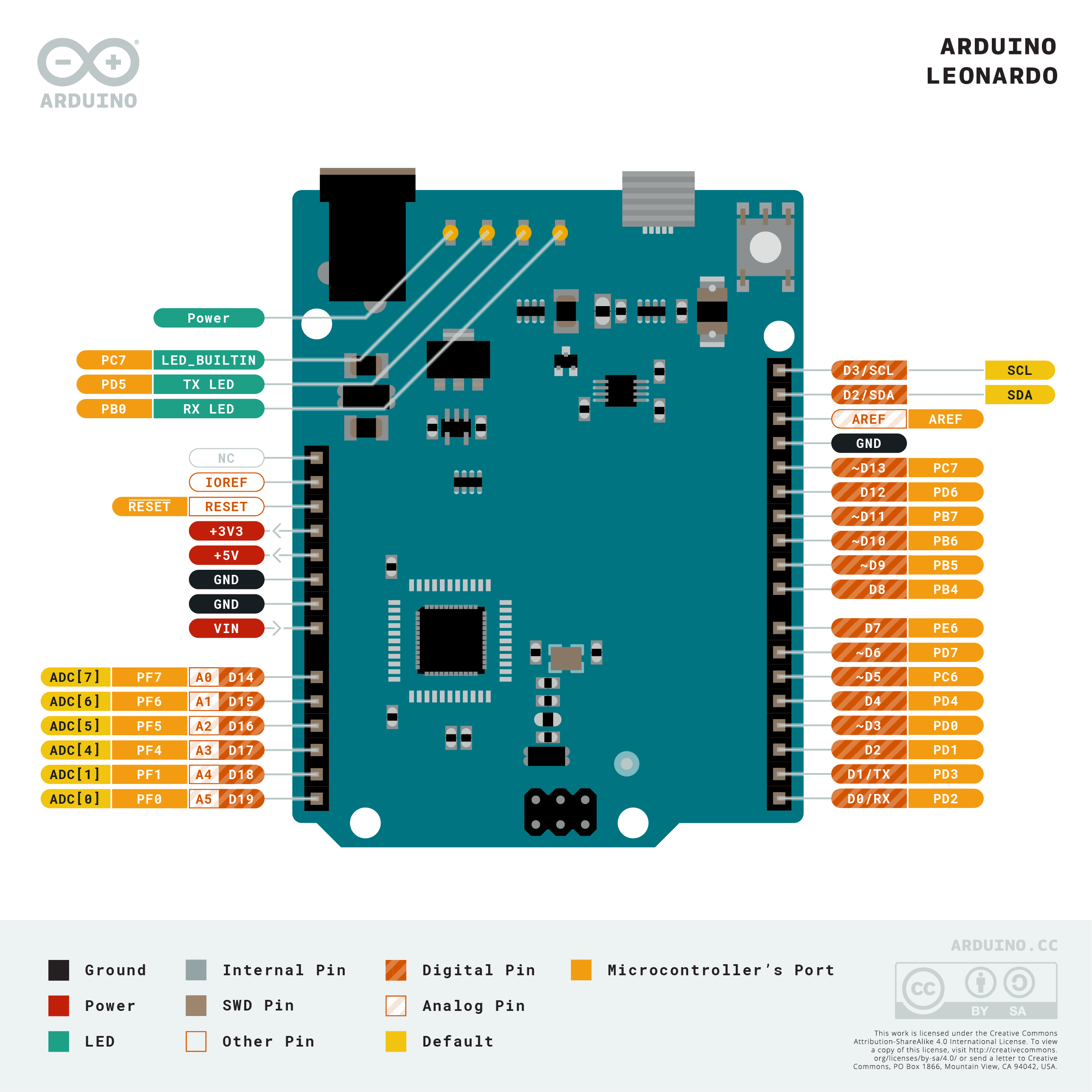
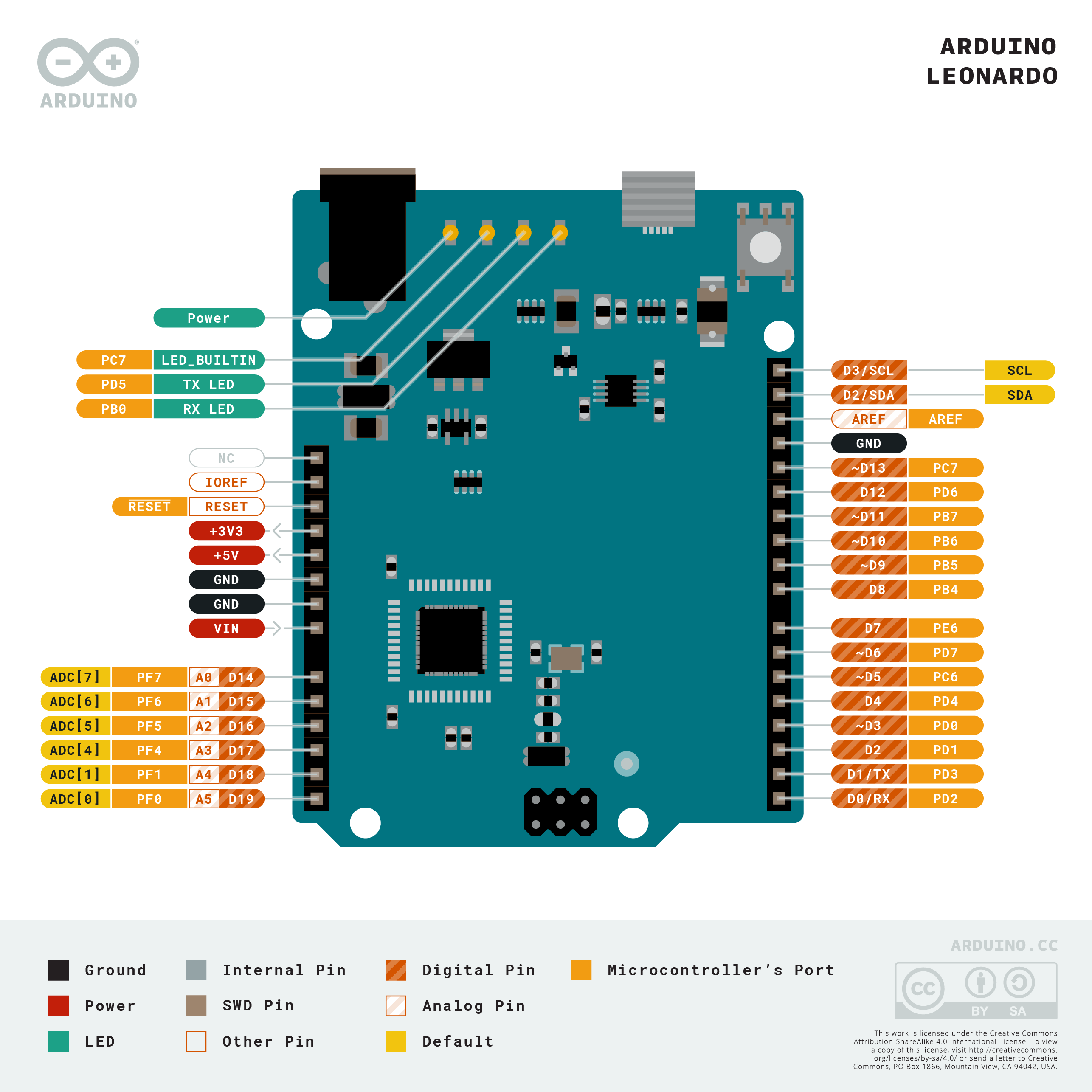
on arduino leonardo, it seems from pinout that D2 and D3 are used by i2c

 kindred rain
Oh wow.
There are other pins specifically labeled as SDA and SCL.
But I guess that is just for shield compatibility.
vivid rock
yep, they duplicated these pins
which, of course, explains why you have i2c bus problems when the buttons are pressed 🙂
kindred rain
Bingo!
Thank you so much!
That will be pretty easy to fix in the next revision of my board.
vivid rock
no problem
indeed, this seems to be an easy one
paper mist
Do you now see it in the I2C scanner and the example works?
@stuck coral the backlight from the example works, but there is no text at all. I will try some stuff when I get home, including seeing if i2cscanner sees it
shadow wharf
Can anyone tell me the maximum packet size for the SH1106? I've done some testing and I can send 33-byte packets consisting of 1 control byte and 32 data bytes, but I can't see this limitation mentioned in the datasheet. It simply says that the cursor will increment by one after every data byte up to 0x83.
I tried emailing sino wealth as they seem to manufacture the chip but I got no answer.
north stream
It does say you must stop sending data when the BUSY flag is set, or send slowly enough that it doesn't go busy.
shadow wharf
it says data transfer may be initiated when the bus is not busy, the limitation is present regardless of the clock speed I use for the transfer and it's always the 33rd data byte
I'm using I2C to write to it
north stream
Maybe the maximum packet size is 32 bytes?
shadow wharf
Maybe it is, but I'm not sure and that's why I'm asking if anyone has enough experience to tell me it is for sure
for every 32 bytes of data, I'm sending 5 bytes of command bytes. For my case that means 160 bytes of command bytes to fill 8192 bytes of data, which is about 1.95% of the total payload. This is decreased from my initial approach of 640 control bytes to fill the same 8192 bytes, which is 7.81% of the total payload. If I were to manage to write it to the full length that I would like to, it would be 0.05%, or possibly as low as 0.0006% if I can write the entire framebuffer in one swoop
That would be a significant improvement in performance, so I'm curious if it's something I am able to do
north stream
<2% doesn't seem "significant" to me, but perhaps I'm missing something.
shadow wharf
if you compare 2% to 0.05%, that's a 4000% increase in performance
north stream
Not really, you're going from 98% utilization to 99.95%
shadow wharf
okay you're right, a 4000% reduction in control bytes sent is a more accurate way to put it
north stream
True. It's like the idea of going from 500MPG to 1000MPG. It only saves you a gallon every thousand miles. Going from 16MPG to 23MPG is a much larger savings.
shadow wharf
I redid the math, I'm sorry for being too quick on it before.
The entire framebuffer is 8192 bytes. The necessary control bytes to send is 160 currently and 40 theoretically. That means a reduction of control bytes sent for the same payload of 75%. For the given payload, that's an extra update every 68.27 loops in isolation
 trim hatch
Hi, I recently bought a BMP180 sensor to use as an exhaust control thing in my kode rocket. I have it hooked to an arduino mega. I connected the SCL and SDA on the sensor to pin 20 and 21 to the mega. The issue is that when its connected, all serial communiation stops. Like nothing gets printed to the serial monitor. I am also using a REYAX lora transceiver, and thats not the issue because when I disconnect the transceiver the issue still remains.
cedar mountain
Just checking for some obvious things... are power and ground also connected to the sensor? Are you using an Adafruit breakout board with level shifting? Does the example code work or are you trying to integrate this into your own codebase?
 dusk arrow
Hi, has anyone tried using a Nextion TFT LCD with an Arduino? I recently bought one and am trying to connect it to an Adafruit Grand Central M4 board. The LCD powers up, but it doesn't transmit data to the M4. However, when I test the same sketch on an Arduino Uno, it works. Any help is appreciated.
trim hatch
Hi @cedar mountain, it is connected to power, and no im not using an adafruit breakout board.The example code does not work.
 north kelp
@dusk arrow How are you powering the Nextion? Surfing around, I see people recommending an external 5VDC 1A power supply for it.
dusk arrow
@north kelp I'm powering the LCD off the 5V pin from the Grand Central M4. The few online tutorials I've been trying to follow do the same thing.
north kelp
@dusk arrow Looks like there are a few variations of this display. Here is Nextion recommending an external supply. I’d try that.

NX4827T043 Overview Nextion Models Specifications Electronic Characteristics Working Environment & Reliability Parameter Interfaces Performance Memory Features Product Dimensions Overview Nextion is a seamless Human Machine Interface (HMI) solution that provides a control and ...
Also I’d note that the max power available on the 5V, 3.3V, and Vin pins on the GC M4 is 500mA, combined, when powered via USB.

Adafruit Learning System
This dev board is so big, it's not named after a Metro train, it's a whole freakin' station!
dusk arrow
The LCD powers up from the Grand Central M4. I'm not using any other power pins on the board, so it should be able to reach the 500 mA peak for the 5V pin like the link mentions. I've tried using different UART RX/TX ports as well, but none of them seem to work. The same sketch with an Arduino Uno works, and the 5V pin on the Uno can only draw 400 mA max.
 regal monolith
void sendVal(String label,int val)
{
  digitalWrite(led, HIGH);
  Wire.beginTransmission(9);
  Wire.write(label);
  Wire.write(val);
  Wire.endTransmission();
  digitalWrite(led, LOW);
}``` why can't i send a string variable over the i2c busyou can send a string - note lowercase - which is C-type stirng, i.e. a Null-terminated array of bytes
If you want to send String - note uppercase, which is a C++ string type, you would need to convert it to string first
elder hare
so here im sending a response when "001" (Request Info) is sent to the ESP32
    DynamicJsonDocument doc2(256);                       // Init Dynamic Json Document
    String jsonData;                                     // Make Json Variable To Store Outgoing Json

    if (doc["001"] && doc["001"] == "yes") {             // Request Info

        Serial.println("Requested Info");

        doc2["300"] = DeviceType;                        // Device Type
        doc2["301"] = DeviceName;                        // Device Name
        doc2["303"] = DeviceLEDType;                     // Device LED Type

        serializeJson(doc2, jsonData);                   // Serialize Json
        webSocket.sendTXT(num, jsonData);                // Send Json Data Via Socket
        Serial.println(jsonData);
    }
Printing out jsonData it looks like this
{"300":"ESP32","301":"Matrix Display","303":"Matrix"}
perfect! now on the other end
void MainWindow::onRequestedInfoReceived(QString message)
{
    qDebug() << "[SOCKET][INFO] Requested Info : " << message;
}
Printing out message looks this
[SOCKET][INFO] Requested Info : "{\"300\":\"ESP32\",\"301\":\"Matrix Display\",\"303\":\"Matrix\"}"
why the \ because of QString?
north stream
It's printing it as a string (delimited by quotes) but the string contains quotes, so they need to be escaped so they don't terminate the string.
 copper wren
Im trying to make a 2 key mechanical keyboard for OSU! with a pro micro clone. (idk is that even count as an arduino?) Ive never done an ardino project before but I do know how to soldier. How do I code the board be a keyboard. And how would I soldier the 2 switches to the board.
north stream
You can set the USB type to "keyboard" in the Arduino IDE, and use the Keyboard library to provide keyboard functionality. Normally switches are wired between I/O pins and ground, and configured with "pull-up" resistors to provide a default level of "high", then when the switches are actuated, they pull the pins to "low".
copper wren
Buy Pro Micro Compatible with Arduino ATMEGA32U4 5V 16MHz Board Free Pins: Home & Kitchen - Amazon.com ✓ FREE DELIVERY possible on eligible purchases
north stream
The 32U4 boards support different USB types, yes.
copper wren
does this board use the regular arduino sofware
north stream
I'm not sure, but if it isn't built in, you can add that to it easily with a plug-in.
north stream
You might be better off buying the AdaFruit board and following the learn guides.
north stream
You can try using the learn guide for a different 32U4 board for the steps for configuring the Arduino IDE https://learn.adafruit.com/introducting-itsy-bitsy-32u4/
copper wren
is that the same board in the tut as the one I liked in amazon
and what voltage board would I need
north stream
It's a different board, but hopefully the Arduino setup would be the same, you'd just choose a different board.
Either voltage will work, the 5V board is faster, but for a 2-key keyboard, you don't need much processing speed.
copper wren
ok so If i bought the itsybitsy 32u4 I would just need to soldier the keys to a specific pins, then code it
or figure out how
north stream
Right. There are even tutorials on building custom USB keyboards like this one https://learn.adafruit.com/pro-trinket-keyboard
copper wren
thanks
wait
https://github.com/Aplyard/Aplx2 this page has a bunch of files

GitHub
A simple 2% keyboard for osu! Contribute to Aplyard/Aplx2 development by creating an account on GitHub.
for this specific board
should I just buy the board that I liked from amazon
and there is a full tutorial
Should I just do this
north stream
Worth a try, I suppose. There are other Pro Micro vendors too.
copper wren
wdym by other pro micro vendors
north stream
There are other places you can buy a Pro Micro
 chrome cape
Is it possible to partially fry a board meaning that it appears to get power but will not run a sketch?
 sturdy bobcat
Yes.
obtuse spruce
Been there, done that, bought the tee-shrit, wore it proudly!
(That is, after I panic'd 😱 as I fried my only Feather M4 less than week before I was suppose use it in a live performance.... finally found an old M0 😥 , re-jiggered the code 🤔 , made it work... 😂 and the performance came off with out a hitch 💪 . -- it was an emotional week!)
stray sierra
Hello, i want to make a console on wwb style like tasmota. Is there any tutorial on how to do it?
 carmine canyon
hey, i wanted to use ros actions with arduino ,but they're some issues(https://github.com/ros-drivers/rosserial/issues/182 as per this ros actions arent supported with rosserial)Is there any way I can control my stepper with ros actions(similar to this https://answers.ros.org/question/338160/custom-action-messages-in-rosserial-arduino/)

GitHub
Hi, I was wondering if rosserial supports actions? I'm considering using rosserial to implement the controller of a robotic manipulator, which is programmed in an Arduino Mega, by directly ...
I am trying to run an action server on my arduino to control 4 stepper motors. I started by creating my motorpose.action file: #goal definition - 4 angles to be sent to arduino float32 baseAngle float32 mainAngle float32 secAngle float32 toolAngle --- #result definition - Stat...
 grim peak
Hello friends! Is there a way to get the RSSI (Received Signal Strength Indicator) of a specific wifi signal using mkr1000 or wifi101? For example, I want to store the RSSI information in a variable for the wifi of my house and another variable for the RSSI of the wifi of my cell phone
safe shell
@grim peak see https://www.arduino.cc/en/Reference/WiFiRSSI (I'm shocked that Arduino generic wifi scan only returns the number of networks https://www.arduino.cc/en/Reference/WiFiScanNetworks ...on some platforms like ESP32, scanning returns all of the relevant info on each AP... ssid, bssid, rssi, channel, encryption)
grim peak
In the syntax of RSSI (); It appears that it accepts the parameter of (wifiAccessPoint).
Will that help me to specify the signal I want to scan?
How should I write it? What type of value does the function accept?
safe shell
as in the example: long rssi = WiFi.RSSI(); will give you the connected AP (there may be buried code to return RSSI and other characteristics of other APs... I wish the Arduino docs were more complete)
found an example of getting all the info from scans: https://www.arduino.cc/en/Tutorial/LibraryExamples/ScanNetworks
 unborn frost
hey, recently got a sound sensor off amazon: https://www.amazon.com/gp/product/B07J6N734S/ref=ppx_yo_dt_b_asin_title_o00_s01?ie=UTF8&psc=1. I assumed that it would have a pretty good range maybe 0 to 800 on the arduino analog pins. all 3 of them are giving me ranges of about 100 - 112 (changes when i adjust the pot but same range of about 12) any ideas why this is happening? bad boards? already changed analog pin on my nano to see if that was the issue with no help
Amazon.com : Comidox 3Pcs High Sensitivity Microphone Sensor AVR PIC Sound Detection Module for Arduino : Camera & Photo
and both leds are lit at all times. from what i understand the second one should only be on if it detects sound
cedar mountain
Well, without a datasheet or something, there's no way to tell what you should expect. I think the pot is only used to adjust the digital-output threshold, but it won't affect the microphone gain.
 grand basin
Very basic question. Trying to test a .96" OLED (not adafruit brand) on the Teensy 4.1. The code doesn't compile because it can't find the libraries, which is strange because I opened from the zip files and the libraries are both visible in the "recommended libraries" section, as well as are #included (wordplay, it's #include correctly in the code) in the sketch that won't compile
here is the error:
In file included from /Users/coryoleson/Documents/Arduino/libraries/Adafruit-GFX-Library-master/Adafruit_GrayOLED.cpp:20:0: /Users/coryoleson/Documents/Arduino/libraries/Adafruit-GFX-Library-master/Adafruit_GrayOLED.h:30:32: fatal error: Adafruit_I2CDevice.h: No such file or directory compilation terminated. Error compiling for board Teensy 4.1.
oh gosh darnit nevermind. I needed a whole different library. Thanks anyway lol
 manic wren
Hi! Was wondering if anyone here could help me with an issue, my ESP8266 suddenly won't connect to my WiFi router anymore, where as previously it was doing ok.
Tried even just the simplest WiFi connection code that I know was previously working, to no avail. The issue is that it can't get that wi-fi connected status. Tried restarting the router too. Other devices can connect to it ok.
Any help on this would be great thanks! 😄 Was my first time using the ESP8266 yesterday so it was a bummer to discover this issue.
Edit: After hours the problem just resolved itself lol.I thought there was nothing wrong with the stuff I connected to the ESP8266 since I ran test codes that only ran them specifically and they were all working, except for WiFi.
But upon disconnecting everything Wi-Fi worked again. Have now re-attached them, and Wi-Fi still works. I suppose there was a connection issue there somewhere that I just somehow missed, things are still in the breadboard and wire stage so that might be it.
 white briar
Hi there, someone used arduino with an IR receiver with the IRremote library? sometimes when reading the results value (in HEX) i'm having some 0 hex values and wanted to know why that. Thanks 🙂
`
#include <IRremote.h>
IRrecv irrecv(11);
decode_results res;
void setup() {
// put your setup code here, to run once:
Serial.begin(9600);
irrecv.enableIRIn();
}
void loop() {
// put your main code here, to run repeatedly:
if(irrecv.decode(&res)){
Serial.println(res.value,HEX);
irrecv.resume();
}
delay(100);
}`
 deep salmon
I'm having this odd power problem. When I run the adruino via usb, everything runs fine. As soon as I hook up my 12v battery to it, the voltage regulator gets hot to the touch. Any ideas?
stuck coral
What board do you have?
deep salmon
elegoo uno R3
gilded swift
Probably over voltage on the regulator
deep salmon
the board spec says it can handle up to 20v
should I add in a buck converter to drop the 12v down to 7-8?
gilded swift
Are you plugging into the barrel adapter?
deep salmon
yep
stuck coral
What else is connected to the UNO? Since its a linear regulator, 12V will make more than double the heat as 5V input, and no @gilded swift
deep salmon
only thing connected is a 5v stepper motor
stuck coral
That will do it
deep salmon
should I not power the stepper with the board?
stuck coral
I would recommend a buck regulator, 12V is the very high end of what that regulator is rated for, its more for 9v batteries
deep salmon
gotcha, I'll give that a go, Thanks!
stuck coral
You're welcome @deep salmon but I would like to confirm, the board still works fine with 12V battery? Just gets hot?
deep salmon
Amazon.com: ELEGOO 5 Sets 28BYJ-48 ULN2003 5V Stepper Motor + ULN2003 Driver Board for Arduino: Camera & Photo
here are the steppers I bought
stuck coral
Sigh that ELEGOO product is not documented well. After looking at the motors and regulator I am continuing to think you are drawing too much current for a 12V input with those steppers
The turn off after 30 seconds is probably the thermal auto shut off
Buck regulator will be a good solution
deep salmon
one amazon comment from elegoo said they tested up to 500ma, which is a lot
i'll splice in a buck converter and see what happens
stuck coral
Looking at the regulator it has an absolute max of 800mA when there is a good thermal solution so I would agree with the 500mA figure. But thats not a lot when you're using stepper motors
I bet your USB protection circuit is screaming at you
deep salmon
I guess I'm a little lost, are steppers just not good to use with an arduino?
vivid rock
Steppers are fine to use with arduino.
But powering them from 5V pin of arduino may be a problem
stuck coral
Yep, they just draw a bit of current
Hence why you have the driver
To make the low current arduino drive the high current device
deep salmon
gotcha, so should I just direct connect the stepper power to the battery and forgo the Arduino entirely? Use a buck converter to drop the voltage down to 5
vivid rock
How is your stepper driver board powered? do you connect it to 5V pin of arudino ro directly to 12V battery?
deep salmon
5v pin atm
vivid rock
that's the problem, indeed.
If the stepper board and motor are good to use 12V power (please check description!), then connect the driver board directly to 12V battery; in addition, connect ground of stepper board to ground of arduino, and this should take a lot of load from the regulator on arduino board
if they can not use 12V, you would need a separate buck converter
stuck coral
Yes those drivers have a 12V input
BUT
Steppers in the amazon link are only good for 5V
vivid rock
should be
stuck coral
Yes, and the LM2596 that are cheap and popular on amazon are good up to 3A so you have some headroom
deep salmon
perfect! I'll do some soldering and get that going real quick. Thanks guys!
vivid rock
I remember trying to use a 7805 linear regulator to drop voltage from 12V to 5V in one of my earlier designs. Even with large heatsink, it got so hot that I got burned - literally. After that, I learned to use buck converters
stuck coral
Yeah, I mean linear regulators have their place, but in most cases buck converters are best fit
vivid rock
I was tempted because 7805 is just one component, and buck is a separate add-on board, and I was lazy. And I didn't know any better
 robust lotus
I have a adafruit wifi m0. in the docs it says I should not power it externally because there is no back flow protection (I could send voltage back on the usb cable) However I need more power then it can output for my project so I need something like a breadboard power supply. I very much want to see the Serial.print statements while working with these higher voltage peripherals. I can think of 2 ways I might solve this (I am a bit of a noob) 1. Connect the ground from the bread board power supply to the board and connect the USB cable. In this config I should get the serial out and things "Should Work" 2. Attach a USB -> Serial board to RX and TX on the board to get the Serial output while the board is powered externally. Advise? other options? Am I being dumb? 🙂
stuck coral
Could you link me to the note you mention?
I see in the schematic what you are referring to
And you are trying to add what sort of external supply?
robust lotus
fetching info.... 😉

Adafruit Learning System
ARM Cortex M0+ with fast & fun wireless built in
"The Feather is not designed for external power supplies - this is a design decision to make the board compact and low cost. It is not recommended, but technically possible:
Connect an external 3.3V power supply to the 3V and GND pins. Not recommended, this may cause unexpected behavior and the EN pin will no longer. Also this doesn't provide power on BAT or USB and some Feathers/Wings use those pins for high current usages. You may end up damaging your Feather.
Connect an external 5V power supply to the USB and GND pins. Not recommended, this may cause unexpected behavior when plugging in the USB port because you will be back-powering the USB port, which could confuse or damage your computer."
stuck coral
What sort of external supply are you using?
robust lotus
I have this as I need to power a LCD 16x2 with 5 volts and a relay with 5 volts.
I have 12v running into the breadboard power supply. From there I can take 5v for the stuff that needs that. and 3.3 for the 3.3 stuff
stuck coral
Okay, so you have three options. One is to just connect via usb anyways, it is unlikely to damage anything but as the note mentions, it possible. Seconds option is to mutilate a USB cable which I have done. Or third is to add a protection circuit to the USB
robust lotus
I like 3rd and have no idea how to do it. anywhere I can RTFM? I am a python, ruby, c# programer for 20 years getting into Arduino and C++, I don't know much about circus or circuit design but I am enjoying learning
I am thinking it would Involve a Diode 🙂 but beyond that I am clueless
stuck coral
Well now that I think about it, adding a diode or fet here would be hard since the USB connector is on the same PCB as the 5v input and is small...
I think the best/easiest way is to mutilate a cheap USB micro cable.
robust lotus
so split out the power lines on the cable to pull from the power supply?
stuck coral
No, just cut the power wire so no power flows from the PC to the microcontroller. Note then you will always need external power when using the cable.
I have a cable I did the same to I use for similar use cases
robust lotus
ahh..
stuck coral
Make sure to mark it so you dont use it in the future thinking it will supply power. If you could get between the usb and vbus rail on the PCB you could just add a diode or fet
robust lotus
that makes sense.
as a side note I did try this https://www.amazon.com/gp/product/B07D6LLX19/ref=ppx_yo_dt_b_asin_title_o07_s00?ie=UTF8&psc=1
and I could get it to work on my Arduino uno where I was externally powered and was seeing serial output via the RX and TX pins
I just could not get the same result on the feather
I would love this to work because then I could just take a small usb cable from my power supply into the feather. This would power it as intended and charge the battery but I could still see the serial output.
stuck coral
But then you cany program it unless you get a new bootloader
And I mean, that has the same issue
If you used that, then the 5V of your computer is on the same rail as your breadboard psu
grim peak
If I have an arduino MKR1000 or a wifi module in AP mode, how can I obtain the information of the networks that are connected to the access point?
 zenith orchid
Hi I have a weird thing...so I'm trying to connect to a hoverboard esc / motherboard....but I'm having issue doing so....I was able to connect RX and TX and 5V...but I'm just getting a beeping noise...and Arduino isn't picking up what type of board it is
stuck coral

PubNub
Learn to remotely configure the WiFi credentials, or other settings, on your Arduino MKR1000 by transitioning in and out of access point mode.
Did you connect a ground @zenith orchid?
 hybrid crown
Hi everyone,
I would like to make my own animated ledstrips with addressable ledstrips. But I have never done anything like this so I’m a total newbie.
I have been searching on Google for hours already to look for what I need to buy. I want to have a 5m strip (without the need to any soldering), which I can program by myself. After I finish programming the leds it needs to be powered by an adapter.
Is there anyone who knows what I need to buy? (I live in the EU)
vivid rock
I would suggest to start by reading Adafruit Neopixel Uberguide: https://learn.adafruit.com/adafruit-neopixel-uberguide/the-magic-of-neopixels

Adafruit Learning System
Everything you always wanted to know about Adafruit NeoPixels but were afraid to ask
 rotund condor
Hey all I’m looking for information on burning a boot loader to 328. It’s my understanding that the 328pu’s have bootloaders already burned. So will the process to burn the boot loader work for any of the 328 packages that’s don’t have the U in them?
elder hare
Qt Side:
void paintPixel(int row, int Col, uint16_t Color);

connect(button, &QPushButton::clicked, [=]() { MainWindow::paintPixel(r, c, 0x0000); });

void MainWindow::paintPixel(int Row, int Col, uint16_t Color)
{
    qDebug() << "Row :" << Row << "Column :" << Col << "Pixel Color:" << Color;

    QJsonArray pixelInfo;
    pixelInfo.append(Row);
    pixelInfo.append(Col);
    pixelInfo.append(Color);

    socket.sendCommandStrip(QString("pixelPainter"), pixelInfo);
}
ESP32 Side
    if (doc["pixelPainter"]) {
      JsonArray src = doc["pixelPainter"].as<JsonArray>();
      const int Row = src[0];
      const int Col = src[1];
      const uint16_t color = src[2];
      Serial.println(Row);
      Serial.println(Col);
      Serial.println(color);

      display.drawPixel(Row, Col, color);

    }
output from ESP32 is
15  // Row is OK
16  // Col is OK
0   // This is wrong :S i only get 0 when it should be 0x0000
what am i doing wrong?
hybrid crown
I would suggest to start by reading Adafruit Neopixel Uberguide: https://learn.adafruit.com/adafruit-neopixel-uberguide/the-magic-of-neopixels
@vivid rock Thanks! I contacted a small company in my country which sell parts of this article. As I do not have the knowledge about how to make it or even how to deal with the volts comparing to trip-length
 grand hazel
how do i convert a signal oscillating between 1-3 volts into 10-30 microvolts?
i tried adding a resistor, but the wave looks jittery and not so great
stuck coral
An op amp, I guess a voltage divider might be possible but I think an Op Amp is what you are looking for
grand hazel
thanks
cedar mountain
Just bear in mind that there are a lot of potential noise sources at the microvolt level, so getting a clean signal that weak might be tricky.
grand hazel
just started learning about electronics and one thing i'm noticing is nothing is ever simple
cedar mountain
Well, things become simple when smart people spend a lot of effort to MAKE them simple. But if you're trying to follow a path that hasn't been smoothed for you, it won't necessarily be easy.
grand hazel
i'm trying to do too much without getting the fundamentals down
elder hare
@cedar mountain do you know? my problem above, i've tried to send as String :S but then i just get "null" when printing out
 topaz compass
0 // This is wrong :S i only get 0 when it should be 0x0000
You know those are the same value, right?
elder hare
yes i understand that but i need it in the 16bit RGB format 0x0000 otherwise the matrix wont understand the color
topaz compass
so drawPixel() takes 2 ints and a string? Then you need to convert to string
elder hare
yes
topaz compass
if (color == 0) drawPixel(Row, Col, "0x0000"); ?
 rough hazel
For my recent project I have created a custom arduino nano shield for driving four stepper motors, and I am running into significant problem. On my PCB the arduino is powered via the "vin" pin with a 12 volt 2 amp power supply. All of the components on my PCB except the nRF24L01 module, which is powered via the 3.3v pin on the arduino, are intended to be powered through this supply. When I power on the PCB and upload a simple test code to it, the stepper motors randomly vibrate, and do not turn. When I power the arduino with a 9v battery and connect all of the pins to their intended places, except for the vin and a ground pin (on the arduino), the PCB works exactly as intended. Does anyone know why the shield does not work when I am powering everything with the same power supply, but when I power the arduino seperatly it works perfecty? Just to clarify I am using a bench power supply while I'm testing, and with the Arduino powered from a 9v battery the PCB is drawing 1.2 amps. I have linked my schematic below.
vivid rock
Are you using the classic arduino nano, the 5V one?
 reef ravine
and the only difference is substituting a 9v battery for the bench supply at nano Vin?
reef ravine
maybe try a 100uF and a .1uF close to Vin, noise issue?
vivid rock
https://store.arduino.cc/usa/nano-every this one?
A robust board to turn your ideas into reality.
rough hazel
Yep that’s the one
I will do some troubleshooting to see if it is a noise issue. That being said I would definitely be surprised if it is.
reef ravine
me too, i'd assume the regulator would reject most noise, but traces can do funny things...
rough hazel
Yeah...
vivid rock
do you happen to have a power supply with more than 2A?
if your PCB consumption at some moments jumps from 1.2A you are measuring to say 1.8A, it could brownout the arduino
rough hazel
I’m using a bench power supply with a current limit set at 2 amps
vivid rock
can you increase the limit?
rough hazel
Yep
grand hazel
never could figure out how to use the op amp as a voltage divider. my attempt at getting my arduino to output a 13Hz sine wave at 40 microvolts (https://www.tinkercad.com/things/6aq5gRJg0ZW-glorious-rottis-crift/editel?sharecode=Tob-AECxliRMLVyM36Z3fKsjznF74hj6ti_Ya_pV_hA). always seeing output amps as 0 for some reason and the sine wave looks like garbage. also i seemed to arbitrarily picked the value for the capacitor.

Tinkercad
Tinkercad is a free, easy-to-use app for 3D design, electronics, and coding.
having an offset would be nice too
cedar mountain
This is a good resource for getting an op-amp design settled easily: https://www.ti.com/lit/an/sloa097/sloa097.pdf
elder hare
i have 3 R G B that i wan to format to RGB888 and RGB565 but i suck at the bit shifting thing and then making it to a hex string or whatever is it
color.red();
color.green();
color.blue();
so color format
#FF00FF0xFF00
cedar mountain
The first thing to double-check is whether you actually need it as a hex string, or just a combined integer value.
elder hare
@cedar mountain well first of i need the web color format cause im setting background-color: in a stylesheet and the other 0xFF00 is need cause that's the format the Matrix / matrix library understands / accepts
cedar mountain
Gotcha. For the first you could do something like:char web_color[8]; sprintf(web_color, "#%02X%02X%02X", color.red(), color.green(), color.blue());
For the second, it would be like:uint16_t rgb; rgb = ((color.red() & 0xF8) << 8) | ((color.green() & 0xFC) << 3) | (color.blue() & 0xF8) >> 3);
elder hare
so the web color is perfect but the other one :S
Web Color : #AAAA7F
Matrix Color : 44367
do i have todo something more to it?
cedar mountain
I thought you wanted a 16-bit integer value for the Matrix library?
44367 is 0xAD4F.
elder hare
oh so that should work 🙂
im just confused as everything else (even examples from library) all uses 0x0000 format 😛
cedar mountain
That's just how you can type numbers in source code. Whether hex or decimal, it all gets converted to binary voltages eventually, heh heh.
You can print it out that way too, but the variable is just a normal int type regardless.
elder hare
so i just tested and it didn't work :S the color code is stuck at "blue" that is default
cedar mountain
Does it work if you hard-code a value in your code?
 raw forum
Does anyone use a nodemcu esp 8266 for there iot projects?
I am trying to build an iot server but I have problems with connecting my esp8266
#include <SPI.h>

const char* ssid     = "Iphone Raoul";
const char* password = "******";
const char* host = "iotraoul.000webhostapp.com";
const int httpPort = 80;


void setup()
{
  Serial.begin(9600);

  delay(1000);
  WiFi.begin(ssid, password);
  while (WiFi.status() != WL_CONNECTED) {
    delay(500);
    Serial.print(".");
  }

  Serial.println("");
  Serial.println("WiFi connected");


}

void loop()
{
  WiFiClient client;
  WiFi.mode(WIFI_STA);

  Serial.println("connecting...");

  if (client.connect(host, 80)) {
    Serial.println("connected");
  } else {
    Serial.println("connection failed");
  }
}
I am running this simple sketch but I keep getting a "connection failed" with client.connect()
north stream
Presumably you're getting "WiFi connected", so it's connecting to the WiFi. I wonder if it's getting DNS information via DHCP: if not, it would not be able to connect to the host by name. It might be worth seeing if there's an error code giving more information as to why the connection failed, and/or trying to connect by IP address instead of name. Note that it seems odd to define httpPort and then use a literal 80 in the connection request.
raw forum
Yes it is connected to wifi // how can I check if it is getting DNS information? // I tried connecting to the ip adress of google.com , didn't work either and the function client.connect() can be with either ip or url // yes I know haha , I was trying multiple things, thats why it is a bit messy
north stream
If the IP connection didn't work either, that wouldn't be a DNS problem, so there's (at least) another problem. It could be a routing issue. What I'd try first is an IP connection to something else on the same (local) network (perhaps the router, if it has any open ports that can be connected to) to see if that works.
raw forum
That is a bit of an issue since I'm in an hotel so it is connecting trough my iphone trough 4g
Is this maybe the issue?
 woven mica
Your code works for me (I get connected on the output)
woven mica
yes
raw forum
Okay thank you, than I think it is the problem that I'm connected trough my iphone and not directly to a wifi router, is that possible?
north stream
Seems possible to me.
zenith orchid
so I was able to hook up UART....but I'm only able to get the board to just beep...which happens when I plug it in, what can I do after hooking up UART to get access to the boards info?
I need someone who's good with serial communication between a random China board and either my pc or an ardunio to my pc....
woven mica
Depends on what board it is
zenith orchid
That's the problem I'm not sure what board it is
It's one of the board from a MOZZiE hoverboard
woven mica
What does it do?
zenith orchid
it's the motherboard for the hoverboard
and they haven't included any information on the PCB
so I"m not sure where to go from here
woven mica
What does it talk to
zenith orchid
It doesn't talk to anything, the motherboard is the brains and the esc
So I have three boards right
Here's it hooked up
I have it hooked up the the computer like this
Through the UART on the motherboard....and when I plug it in...the computer can see it on it's ports.....and the board starts to just make a beeping noise....but I can't figure out how to get any information from the board...so I can then figure out more about it and how to program it
But the thing is...I need to be able to send the same signal from one Arduino or maybe ESP3266...if possible 🙂 So that I can give commands for these six motors to go forward or back at the same time
obtuse spruce
Just because the main board has a serial connector doesn't mean that they've programmed out to do anything useful. There may not be any command protocol over it at all. It might just be used during development or calibration. You might have to bridge a jumper to get it into that mode, and even then you may not be able to do much over the serial line.
stuck coral
Or if something needs to be sent to get it to print anything
zenith orchid
Well so that's what I'm trying to figure out......first....how to connect to it...which I have...it pops up as COM3....and then second...okay now that I"m connected.......what information can I pull from it, and how do I do that
obtuse spruce
There is no way to know without technical docs from the source. You could try to reverse engineer it... But that can take a lot of time, and may not yours results.
Do you have anything to go on? Any reason to suspect that there is a command protocol on that line?
zenith orchid
Well the only hope I have is to reverse engineer it......it's been done...but on old version of the hoverboards
Yes....only because lots of other people online are doing this...and they are using UART...which this has....which tells me theirs gotta be something their....or why would they have kept it on the board at all
woven mica
If people on internet are doing it, then try to send what they are sending
zenith orchid
Well that's the thing, the way they are connecting to it...I don't have those tools atm....
It's called a ST-LINK v2
and they use this software with that piece of hardware to connect to the board from USB
obtuse spruce
Find projects that did this, and try out what they did. Try the baud rate and settings they used, then if you some interaction at all... Try the commands they reversed
zenith orchid
but I'm connected right now through the UNO
stuck coral
An STLINK is a external debugger, which is not UART
zenith orchid
This is all of the information that I could pull off it......but it does connect through UART
stuck coral
That connection is to the USB UART converter
Not that there is valid UART communication
woven mica
Se I assume the board are using STM32
stuck coral
If you open the serial port, is there anything at all, no gibberish?
zenith orchid
Well that's what I"m not too sure of...I think it might be.....let me try get a good photo of the chip
No gibberish at all
Give me a second to take this photo
Okay cant get a photo.....camera isn't good enough one second while I type of what's on this board
Microchip dsPIC33EP128
GM810-I-PT
That's the second line
1633JMD is on the third
woven mica
This board uses a PIC microcontroller then
stuck coral
Yeah, so with the STLINK they were uploading a custom firmware it sounds
zenith orchid
Yes...that's what they were doing
stuck coral
Do you have a custom firmware for this specific board?
zenith orchid
No I don't
woven mica
PIC microcontrollers are less DIY friendly than STM32. I dont know if they could be programmed with st-link. Never used them.
zenith orchid
mmmh shoot....
stuck coral
I dont think you are looking at the right chip, @woven mica is right
I dont think you can program a PIC with a stlink
zenith orchid
So what should I do?
stuck coral
Are there any other chips you see?
zenith orchid
uhm.......not really......I mean I could read off the mosfets?
stuck coral
Nah, so the PIC and the BLE chips are the only chips you see front and back excluding any fets?
zenith orchid
Pretty much....atleast the chips that look like you could program
The weird thing is this board has two uart ports on it
stuck coral
Where do they both go? If you follow the traces from both the TX pins to which chips do they lead you to?
zenith orchid
brings me to that main PIC board
stuck coral
Both of them?
zenith orchid
Yeah looks like it
One of them might also have a tx running to this 12v gnd
But they both deff connect to the pic chip
stuck coral
Strange, and no gibberish on serial from either of them?
 lost saddle
Hello, I am trying to use an Adafruit Trellis M4 as a midi controller, but I doin't understand how to get the header files installed that the script needs. I have reset the bootloader and my computer sees the midi device. The Arduino software sees it as the proper board. I see the .h for Sensor and the other on github. How do I get them in my computer so the Verify/Upload can run successfully. Thank you.
stuck coral
Do you know if the library is in the library manager?
lost saddle
I'm sorry, how do I know which library? I do show one that supports the Trellis M4, yes.
stuck coral
Well you mention needing header files for your sketch, which libray were you trying to install?
lost saddle
One moment.
zenith orchid
Yeah so one side doesn't do anything at alll the other side...when I plug it in just makes the beeper go off
But nothing on the serial monitor
lost saddle
Sorry for the delay. Maybe this is it. I went to Update the Adafruit NeoTrellis M4 library and it said it needed more, including the Adafruit Sensor library so I told it to proceed. I think that looked like my issue and I will let you know. Thank you.
stuck coral
Did you try both while swapping RX/TX @zenith orchid?
stuck coral
Disconnect everything
That PIC is 3.3V, and you are giving it a 5V serial signal
So As mzero points out, if you dont know that it is supposed to output something, somethimges it only outputs under certain conditions or with debug firmware
lost saddle
I just wanted to report back that after updating that Library and its dependencies I had to reset to the proper port, change the MIDI channel to 2 and it works perfectly. Just as cool as it gets. Thank you.
stuck coral
If you have a custom firmware @zenith orchid you'd need to use that, reverse engineering that board is a whole project without it
zenith orchid
I have no way of knowing how to upload anything without more knowledge about what is it and how to communicate with it
stuck coral
You'd need an external debugger that works with that IC, and a custom firmware
And you would need to find a programming header
zenith orchid
I can't even find any info or sheets on this chip
stuck coral
zenith orchid
That's not the same? Is it
dsPIC33EPXXXGP50X
We're looking for dsPIC33EP128
right
zenith orchid
oh god.....I legit am just stuck then....cause I just don't know what I need to do to move forward...
stuck coral
If you want to get info from the board, the BLE might be a better way forward
Use something like the nordic BLE app on your phone and inspect what info you can gather from the BLE characteristics
zenith orchid
Which one...Looks like they have more than one app
stuck coral

nRF Connect for Mobile is a powerful generic tool that allows you to scan, advertise and explore your Bluetooth Low Energy (BLE) devices and communicate with them. nRF Connect supports number of Bluetooth SIG adopted profiles together with Device Firmware Update profile (DFU) ...
zenith orchid
So then, just plug it in and try to see if it's still turning on the BLE
I doubt it turns on from me powering through UART
OOooo
it actaully put something out
stuck coral
The BLE or serial?
stuck coral
Very nice, if you connect to it, does it advertise gatt?
stuck coral
There you go, the client tab shows the four characteristics you have available to you
stuck coral
You should be able to click them, and see if they are read or write, if read, its telling you something, you just need to figure out what
stuck coral
0x1800 is the device information service which is standard in BLE
stuck coral
0x1801 has indicate, so it will notify your phone when something happens. If you subscribe to it you can see any values it sends and try to figure it out.
0x180A actually looks like the device infomration, I dont have the IDs to memory. I'm going to guess 0x180F0 contains most of the info you want
zenith orchid
What am I suppose to do with this information though
It's not letting me send any commands or anything
stuck coral
You need to figure out what the read info means, and writing will send it data, I dont remember which but the up and down arrows are to read and write
zenith orchid
Yes I can see that....but this isn't going to give me access to the PIC to reprogram it
plus I still have no way of connecting this to a device like an esp3266
so then I can control this wirelessly
stuck coral
That is true, in order to do that you need the stlink and a custom firmware file
zenith orchid
But why would I need that STlink
if it's a PIC
Their aren't any UART ports on the bLE
stuck coral
Well, external debugger, have not seen the stlink work with a pic, you mentioned you saw someone do the same with a stlink but on the board you were talking about there must have been a stm32
And no
But the uart might not get you what you want anyways
Even if the firmware on it now let you
zenith orchid
mmmh.....alright...that makes sense...but I'm still wondering then what I would do with the ST link
stuck coral
I corrected myself to external debugger
You need a external debugger
The pic uses the pickit
zenith orchid
What if I used an FTDI
stuck coral
That is a serial device, to program a custom firmware you need a debugger
zenith orchid
Right but wouldn't that device be able to bring me to a bootloader
stuck coral
I would be amazed if that thing had a bootloader
And do you have a spec for that bootloader?
stuck coral
PICs commonly do not have bootladers when in products, possible but not common irl
stuck coral
Yeah
zenith orchid
How can I know if this will even work though