#help-with-arduino
1 messages · Page 72 of 1
 obtuse spruce
obtuse spruce
obtuse spruce
so - you have
long stepSpeed = 316.0299659;
but several things:
-
longcan't represent a non-integer. You probably want the type to befloat. -
While the call
setSpeedtakes a floating point value, internally, the library converts this to number of milliseconds between pulses of the stepper, and stores that as along, hence integer. In your case, it'll compute 3ms between steps. And that's as accurate as it is going to get. Furthermore, the accuracy of miliseconds in Arduino depends on the board design and varies widely. If you need a very accurate rotational speed over a long period (hours), you're going to have to do quite a bit more work.
- It makes very very little sense that
-stepPseed*10worked - I susggest that some debugging is needed. UseSerial.print("speed is: "); Serial.println(stepper.speed())to see what speed the stepper is using at various points in your code.
 royal lava
@obtuse spruce it doesnt have to be on the dot but the closer i can get it the longer I can record. I really only need like 6 minutes though.
obtuse spruce
Sadly, if you ask for a speed of 316.0299659 steps/second - what you'll get is 333.333333 steps/second - which is about 5% off... and that's not counting the additional inaccuracy from the board's CPU clock (if crystal controlled, much less, but if it is an on-chip oscillator could easily be off by a few more percent)
so, after 6 minutes, it'll be 18 seconds ahead
royal lava
oh wow.
im looking at what the cheap version of the mega has
that i ordered
according to the listing it says a 16 MHz crystal oscillator
obtuse spruce
that should be withing 10ppm - so you're good on that front -
so now you just have to deal with the fact that that library doesn't handle speed accurately.
royal lava
is there a better library I should be using?
obtuse spruce
no idea - I know nothing about stepper motor libraries - I'm just reading the source code to the Adafruit one (that's the one you're using, right?)
royal lava
im using accelstepper
its supposed to be more accurate than the default stepper.h
also for full context i am using it for this with some slight modifications. https://www.thingiverse.com/thing:1133193

Materials
2 x ball bearing 608zz
1 x M8 screw
1 x M5 Threaded rod
5 x M5 nut
4 x M3 screw
4 x 3mm washer
1 x Nema 17 Motor
For cheap motor option (28byj-48) : https://www.thingiverse.com/thing:2841827
1 x 1/4 nut
1 x 1/4 screw
1 x Arduino Uno
1 x Pololu A4988
1 x Wade Small ge...
obtuse spruce
well there are many forks... but you're using this one: https://www.arduinolibraries.info/libraries/accel-stepper
Allows Arduino boards to control a variety of stepper motors.
right?
are you sure you need 316 steps per second?!?!?!
that seems awfully fast
royal lava
its a 10-43 gear ratio. its 316 micro steps I believe 1/16 ill check the calculations in a minute
obtuse spruce
The code in that thingverse uses a speed of 250.1876 steps/second --- but it doesn't use AccelStepper to to do it. It hard codes it using delayMicroseconds() - which a) may not be as accurate as one thinks, and b) they don't do proper timing managmenet in the loop - so it is actually a slower effective speed.
royal lava
i am not using the code as I wanted to be able to reset mine as well with the lcd
and i calculated my steps per second based off the radius and TPI of my main screw
and im using 1/32 steps
 jade lichen
I have a lazy question about the trinket lipoly backpack - do the switch terminals function like the enable pin on a lot of adafruit boards? where it can effectively turn the board off, but the battery will still charge? Or does it just cut the battery circuit?
 cedar mountain
From the schematic, it looks like cutting that switch trace will leave the battery connected to the charging circuit, but disconnect it from the backpack header pin.
 mighty hazel
So... I have a weird issue. I need to tie the EN pin of an arduino together with the EN pin of an ESP32 so that the button on the arduino also resets the ESP32. I can do this with a logic converter but the ESP prevents the Arduino from resetting and therefor prevents code from uploading.
Does anyone know what the correct way to do this would be?
 pine bramble
I've thought about it but not thoroughly. ;)
Start with a pair of schottky diodes.
Peripheral to the discussion, but relevant, is:
I have one of these doo-dads but I haven't used it, yet:
Reset / Enable Controller - KA75330 3.3V Voltage Detector
 stoic void
Can anyone help me use an aurdino to show altitude and air speed in Microsoft flight simulator with a screen attached to it
mighty hazel
Does MS flight sim have an api for getting that data?
mighty hazel
Well, if you can get the API working you probably would just send the numbers via serial to the Arduino.
stoic void
I’m not very knowledgeable on how to access it
I just have a metro i got from adafruit
mighty hazel
This about the new sim?
mighty hazel
Looks like they just released the sdk...
stoic void
So does that mean no?
mighty hazel
Not sure. Most flight sims end up getting a program written for them at some point to add external connectivity, but I don't think they are quick developments.
stoic void
Hm
Like I said I wouldn’t know much about it because im not familiar with any of this stuff at all
mighty hazel
Link2FS is the one I've seen used...
stoic void
In 2020?
mighty hazel
It's for flight sim X
stoic void
Oh
mighty hazel
I imagine something similar will eventually be made for 2020, but who knows when.
stoic void
Yeah
 ebon reef
So quick question. I need to control around 34 individually addressable LED strips for a project I am working on via an arduino. There are several products I am looking at to do this i.e (https://www.adafruit.com/product/1429?gclid=EAIaIQobChMIyr7FofK36wIVA2yGCh0kpwg2EAQYBSABEgL9VvD_BwE) The issue is, how would I address and code each individual strip if I bought something like this? Or would this even be possible with a single arduino?

For all of you out there who want to control 24 channels of PWM, we salute you! We also would like you to check out this breakout board for the TLC5947 PWM driver chip. This chip can control ...
 stuck coral
The addressable LEDs dont use PWM for control, so I dont think that would help you much
ebon reef
What would be the best way to accomplish the strip controls in that case?
stuck coral
Well the question is, are you okay with there being a slight delay between each strip changing? Because with 34 I/O there are not many ICs with that many SPI or I2S so in most implementations you just have a micro with a lot of IO, and bit bang it out but there will be a slight delay between each row updating
There are implementations with shift registers to fix that but thats a lot of shift registers
ebon reef
If thats the only option, then yes that would be fine. It is going to be in a specific shape and the goal is to make it display different things in that shape
stuck coral
Can you reduce the number of strands by chaining them?
 north stream
For jobs like that, I look at the DMA implementations that run 8 strips at a time. https://www.adafruit.com/product/1779

This adapter board connects the Teensy 3.1 to up to thousands of WS2811/WS2812 (a.k.a NeoPixel) and compatible LEDs using the OctoWS2811 Library.It features a 74HCT245 buffer chip and 100 ...
ebon reef
I could potentially chain a few of them together, but it would not cut the number down to something I could just control from just the digital PWM arduino IOs (10-15 maybe?). I would need to do some math to figure out the exact number though.
stuck coral
Its not a PWM signal though, its data
ebon reef
Ah okay.
But yes, would the best option be the OctoWS2811 adaptor that was sent earlier? I'm trying to use an arduino for this aswell as it is partially a school project so would those two be compatible?
obtuse spruce
when you say "individually addressable LED strips" - do you mean strips of NeoPixels? or something else?
ebon reef
Strips of Neopixels, yes.
stuck coral
Which Arduino? And it would be best to reduce the number of strips
obtuse spruce
right - so, other than the delay - is there a reason that you can't organize all the LEDs into no more than 8 strips?
aaaaand if you're using Feather M4 - there is this lovely product: https://www.adafruit.com/product/4537
Since we first started carrying NeoPixels back in 2012, the chainable RGB LEDs have taken over the world. And a big part of that success is due to the simplicity of their wiring - just one ...
(also one for M0)
ebon reef
Alright let me try to explain as much as possible: the LED strips will be in the shape of a power T (university of Tennessee logo) and one of the main features I would like it to have is to display the audio spectrum of the room in the center, so it would "react" to music I play, etc. Then I would want it to display a constant orange/white/checkerboard/whatever color I choose with the press of a button. I figured the best way to do this would be to code in a microphone to display the audio spectrum on each LED strip in the vertical oritentation, in the center and bottom, but not the top two bars, hence why I have so many strips. Basically just picture an overlay of a power T over a visualized audio spectrum, thats the goal.
Also I have an arduino uno R3
obtuse spruce
So, the thing with neopixels is that you can address them, and needn't light them "in strips". You could put them all on big strip and as long as you know the number of each light - you can in software set them. You just map the specturm in software to each light you want lit -and boom.
how many LEDs total are we talking, @ebon reef
ebon reef
Thats a good question, haha. I haven't made the grid as of yet, I just made the measurements for its location today. Shouldnt be more than 750 I would say though.
stuck coral
UNO is said to be good up to around 600 addressable LEDs, not including sampling audio
So the fps would be a bit slow
ebon reef
Alright I'll just have to test it once I get it setup. Thanks for your help everyone.
stuck coral
Oh correction on my part, the ~600 figure for the UNO is more of a RAM limtiation
 modest tendon
This may be the wrong forum, but perhaps someone with more Arduino IDE experience than I will quickly see my error:
I wrote an AVR solution to interface the orphaned TI cc-40 computer to an SD card, bringing a mass storage device to this machine that previously never received one.
GitHub
TI HEX-BUS SD Drive Interface. Contribute to go4retro/HEXTIr development by creating an account on GitHub.
The initial codebase was written in straight C, Makefiles, etc. AVR-based. A few months ago, a new collaborator joined and took the code, imported it into the Arduino IDE, replaced some of the native libs (FatFS, etc.) with Arduino ones, and started hacking in the IDE.
For a while, we've kept the codebase so it compiles in both environments, with a liberal amount of #ifdef ARDUINO. But, we need to shave some space, it's tough to debug two different code paths to do the same thing, FatFS is better than the native SD lib, the native RTC libs are better than the Arduino ones, etc. So, I started working to merge the lib uses tonight.
The following code in my rtc lib compiles fine in native build, but Arduino IDE chokes on it:
*#ifndef ARDUINO
void rtc_get(struct tm time) attribute ((weak, alias("dsrtc_get")));
#endif
I had to put the ifdef around it to get it to compile. The file is a .cpp file (so Arduino will compile it), and the native build sees it as a .c file, but I thought weak aliases were allowed in C++ as well.
Any thoughts are appreciated. I'm not as well versed on Arduino specifics as others.
obtuse spruce
Oh - I know this one!
The key is that dsrtc_get must be the actual linker name. So - the issue is the file where dsrtc_get is defined: If that is a .c file, then you're good... but if it is a .cpp file, then you need to wrap it in some magic:
#ifdef __cplusplus
extern "C" {
#endif

void dsrtc_get(struct tm *time) { ... }

#ifdef __cplusplus
}
#endif
This says that if compiling in C++, then this symbol is to be compiled with external C linkage (in particular, non-mangled name).
@modest tendon - I'm guessing when you said "Arduino IDE chokes on it"... that the choking was in the linking stage.
modest tendon
It was, and I just now read that in a C++ file, you have to use the mangled C++ name in the alias target.
I just tried wrapping it in extern C, but no go. Let me try again.
obtuse spruce
You are wrapping the thing it is aliasing, right? Not rtc_get itself
modest tendon
I was (no go). Now, I tried wrapping them both (also no go).
obtuse spruce
So - just to be absolutely clear, you'll need to wrap any declaration of dsrtc_get in a .h file with that stuff , not the implementation.
modest tendon
OH. DId not know that.
OK, hold on.
Looks like that works. Yay! Thank you. Spent all evening on that.
Is there a way to tell Arduino to compile the C files, so I don't have to rename them all to cpp?
obtuse spruce
and -- if you've left that stuf around rtc_get you should be able to remove it --- it is only need on the delcaration (or definition if there is no separate delcaration) of the alias target (the thing in quotes).
modest tendon
I mean, it looks like it compiles them, but it cmoplains about references issues in the linker until I rename them to cpp.
Yeah, I'll remove the ARDUINO ifdefs now.
obtuse spruce
When compiling a .c file, all declarations in .h files it sees are "C" style (non-mangled). When compiling a .cpp file, all declarations, unless in extern"C" { ... } are C++ style (mangled). So fi you have void foo(int); in a .h file, then include that .h file in both a .c and .cpp file, then you'll have references to two different foo functions. Since foo is defined in either a .c or .cpp file, one of those two references is going to be unmet at link time.
Remember that things declared in .h files that are included in both .c and .cpp files need special treatment.
modest tendon
Got it. The problem is that I don't think Arduino IDE will compile C files. It only seems to want to compile cpp files in the sketch directory.
obtuse spruce
hmmmm.... I've never tried! Of course, the .ino file will be preprocessed into a .cpp file.
modest tendon
Yeah, this is a huge project, and the ino file is basically just a stub.
All of the intereesting stuff is in other files.
Normally, I'd just say screw it, it's a bit enough project that it should be a Makefile project (and it is). But, folks want to fire up teh IDE and click a button and it goes poof to the Arduino board (which the code does support, actually).
obtuse spruce
I get you - my biggest Arduino project is 42 source files... I really would prefer a Makefile for something that big - and full of variants, etc.... But it is open source and it will work out of the box for more people in the IDE... so I keep it IDE working.
modest tendon
Yep, same here.
I appreciate the help. I would have never thought to put the extern stuff in the h file.
 round pecan
Sorry if this is the wrong place to ask, but I'm in need for some beginner programming help.
I'm trying to modify a Neopixel Sketch that normally works with Adafruits Bluefruit Connect, so that it works with my custom app (built with MIT AI2).
The part i'm stuck on is sending and receiving the correct values to change color. I can't figure out what kind of value the sketch expects of me to input.
  if (packetbuffer[1] == 'C') {
    red = packetbuffer[2];
    green = packetbuffer[3];
    blue = packetbuffer[4];
    Serial.print ("RGB #");
    if (red < 0x10) Serial.print("0");
    Serial.print(red, HEX);
    if (green < 0x10) Serial.print("0");
    Serial.print(green, HEX);
    if (blue < 0x10) Serial.print("0");
    Serial.println(blue, HEX);```
https://i.imgur.com/b9rWKA7.png <- this is my output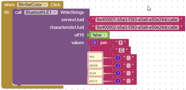
 vivid rock
the sketch expects to get a sequence of 4 bytes
first byte is char "C"
followed by bytes encoding values of red, green, and blue, in this order
each byte should be an unsigned integer between 0-255
there is a number of online tools allowing you to select a color and convert it to RGB values, e.g. https://www.w3schools.com/colors/colors_picker.asp
round pecan
Thank you!
I have tried inputting unsigned integers before, the serial monitor only shows RGB #303235
with inputs 0 255 0
north stream
I'm guessing there is confusion between character data and numeric data. Hex "31" is the digit "1", for instance.
round pecan
edited, put wrong serial montior output. it seems to convert the first three digits to hex.
north stream
Right: it appears that the sending end instead of sending the value 255 (which would be a 0xff byte), it's sending the digits "0", "2", "5", "5", which are 0x30, 0x32, 0x35...
round pecan
{
  uint16_t origtimeout = timeout, replyidx = 0;

  memset(packetbuffer, 0, READ_BUFSIZE);

  while (timeout--) {
    if (replyidx >= 20) break;
    if ((packetbuffer[1] == 'B') && (replyidx == PACKET_BUTTON_LEN))
      break;
    if ((packetbuffer[1] == 'C') && (replyidx == PACKET_COLOR_LEN))
      break;

    while (ble->available()) {
      char c =  ble->read();
      if (c == '!') {
        replyidx = 0;
      }
      packetbuffer[replyidx] = c;
      replyidx++;
      timeout = origtimeout;
    }

    if (timeout == 0) break;
    delay(1);
  }

  packetbuffer[replyidx] = 0;  // null term

  if (!replyidx)  // no data or timeout
    return 0;
  if (packetbuffer[0] != '!')  // doesn't start with '!' packet beginning
    return 0;

}```

this is the thing parsing the whole thing, if thats of any help. I'm too much an amateur to understand what it actually wants as an inputAs far as I can tell, the receiving end is doing what you want it to: the problem is the sending end isn't sending binary data, it's sending ASCII data instead.
round pecan
Okay. I can make it send Bytes, Strings, Floats, Integers and Shorts
north stream
I'm guessing you're having it send bytes already, but in a way that converts them to ASCII. If that's the case, you'd want to figure out how to tell the sending end to not convert the data, but send it as-is.
round pecan
I was sending strings, you can see in the attached picture above. theres also a block for sending bytes.
north stream
Whoops, didn't realize the picture was related. I'm not sure how to configure the output format in that (Scratch?), but I'm guessing "join" is converting things to strings?
If you're going to send the values as strings, your parsing code will need to be more complicated
round pecan
join just joins it into a text like !C02550
north stream
There are two problems with that. One is that it's text and your parser is looking for binary. The other is that there are no delimiters, so the parser wouldn't know if that meant "02" "55" "0", or "02" "5" "50", or the desired "0" "255" "0"
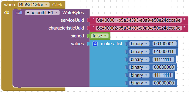
Going to a binary format would solve both problems.
round pecan
Okay, can you elaborate, what would a binary format that look like? Again, sorry for my lack of knowledge on that front 😦
aaah I got it to work. https://i.imgur.com/iGJfsIH.png Thank you so much for the help 🙂
 vivid rock
haven't seen it. Most new boards are 3.3v
actually, how about this? https://www.adafruit.com/product/3514

Try the JavaScript of things with the Espruino WiFi - the world's first open-source JavaScript microcontroller, this time with built in WiFi! This little board has an STM32 ...
 sweet sleet
ooo this looks good
hmmmm
i cant really find the pro mini 5v without wifi now
i get confused by the models.. are these essentially the same but with different pins?
i also need some wires similar to this lol. one male to 3 female in series... how do i search for something like this lol
vivid rock
which models?
sweet sleet
arduino pro mini vs esp8266 vs nodemcu vs wemos d1
all of these..
my friend is recommending arduino pro mini 5v as best for testing my project, but the project needs wifi so i'd' prefer to have a board with it in case it works
vivid rock
for starters, there are different microcontrollers. Wemos D1 and nodemcu both use esp8266 MCU; this is a 3.3v mcu, which has wi-fi built-in; it has limited number of pins, and is not too fast, but more than enough for simple projects
arduino pro mini uses Atmega328 chip; it is a 5V chip and has no wifi built-in. Again, this is not a terribly fast chip, but quite enough for simple projects
sweet sleet
i see
vivid rock
for simple projects, any board works. For more advanced things - when you need many analog inputs, or many PWM pins, or interrupts, or a lot of memory - you need to look at the specs more carefully
at the top of the list are boards such as teensy 4.1 which are about 100 faster than atmega 328, have LOTS of memory, etc - all for $30 or so
sweet sleet
so for my project the board i am using is a d1 mini. this has an RX out.
the power i need to power my components should be fine at 3.3v but i want to try with higher voltage to be sure
vivid rock
what are you pwering?
sweet sleet
esp8266 is a different chip than the 328
but seems they are both fast enough as the guy tested with the arduino pro mini as well
he was able to power with both 3.3v and 5v
i'm powering these displays
vivid rock
can you give link to specs?
sweet sleet
here is my friend who built the displays for me based on this project he made

So after the failure that was prototype 1, I've decided to dispense with trying to be clever and save pins/silicon and just throw an independently controllable h-bridge chip at each of the 14 segments (2 digits per module). After all the L9110S chips I got from ebay were only ...
there are 5v PICs on each of the three display modules
but he tells me he had no issue communicating at 3.3v
vivid rock
usually a 3.3v signal would work with 5v devices
so you can connect an output of a 3.3v board to input of a 5v device
not in the opposite direction, of course
sweet sleet
hmmm okay. it hasn't been working with my wemos d1 which is why i'm looking at other boards
i do currently already have a nodemcu
vivid rock
you can also use a level shifter
sweet sleet
that seems advanced
is there a board you'd recommend i use for a beginner that has pretty much an identical code base/ pin layout to the d1?
or the pro mini?
vivid rock
as far as i see, your opitons are using a 5v board such as pro mini with a separate wifi shield
or a 3.3v board with wifi such as d1/nodemcu with level shifter
i'd choose the second
level shifters are very easy to sue and require no additional programming
check e.g. https://www.adafruit.com/product/757

Because the Arduino (and Basic Stamp) are 5V devices, and most modern sensors, displays, flash cards and modes are 3.3V-only, many makers find that they need to perform level ...
sweet sleet
i've never soldered before
vivid rock
there is always a first time
sweet sleet
okay i'll do it. i have a soldering iron
assuming i have nothing else... what do i need to buy?
breadboard.. wires..
soldering metals

Customers have asked us to carry basic perf-board, but we never liked the look of most basic perf: its always crummy quality, with pads that flake off and no labeling. Then we thought about ...
vivid rock
check this https://learn.adafruit.com/adafruit-guide-excellent-soldering
sparkfun also has excellent tutorials, look them up

have to run now
sweet sleet
thank you 🙂
sweet sleet
How can i connect a tx to this nodemcu to read serial commands?
figured it out. " Serial uses UART0, which is mapped to pins GPIO1 (TX) and GPIO3 (RX). Serial may be remapped to GPIO15 (TX) and GPIO13 (RX) by calling Serial.swap() after Serial.begin. Calling swap again maps UART0 back to GPIO1 and GPIO3."
north stream
Well spotted.
sweet sleet
Ty lol 🙂
I should just be able to read from serial using the serial monitor with it plugged in from the display to the gpio3
You also need to use Serial.setDebugOutput(true) to enable output from printf() function.
 odd fjord
@red dove yes, ask questions anytime. No guarantee of answers . Depends on who is available.
 red dove
@red dove yes, ask questions anytime. No guarantee of answers . Depends on whose available.
@odd fjord Alright thank you ^^
sweet sleet
is it worth it buying a soldering iron and kit
or should i just buy ones already completed and not worry about it lol
 reef ravine
or should i just buy ones already completed and not worry about it lol
@sweet sleet to solder headers?
reef ravine
i think being able to solder is a good skill for a maker to have
sweet sleet
okay fair enough
reef ravine
IDK what the price difference is for header / no header, i always get mine w/o
sweet sleet
is there a cool soldering kit that you would recommend
reef ravine
I'm spoiled with a high end one, but I'm partial to Weller and a basic one is https://www.weller-tools.com/consumer/USA/us/Weller+Consumer/Soldering+Stations/Electronic%2C+Repair%2C+and+Everyday/WLC100CUL
sweet sleet
yeah that's what i'm talkin about
reef ravine
for this kind of work a small conical tip is good
sweet sleet
40w good?
i wonder why it's cheaper on amazon https://smile.amazon.com/Weller-WLC100-40-Watt-Soldering-Station/dp/B000AS28UC/ref=sr_1_1?dchild=1&keywords=WLC100CUL&qid=1598489324&s=hi&sr=1-1
reef ravine
more than enough for a pad and pin, to solder big sheets of copper not so much
everything is cheaper on amazon, buying bulk perhaps?
reef ravine
looks like a small chisel tip, you just need to twist your wrist a little more. so long as its small...
sweet sleet
reef ravine
60-40 Tin Lead Rosin Core Solder is standard, I've never used WYCTIN
some have better rosin (flux) than others. good flux is one of the keys to soldering well
reef ravine
it's fine to start, a good way to learn is to practice on "scrap parts" or bits of wire
sweet sleet
i should get this stuff friday 😮
reef ravine
not "previous day air"? 🙂
sweet sleet
i wish
i hope i make some cool projects with these
i've been held back before by not having a soldering iron
reef ravine
it's always handy for something, even if you breadboard mostly
 fleet pewter
I was awful at soldering and then I got a good iron. Like night and day
A cheapo iron will do the job! But don't get disheartened if it seems really hard; it might be the equipment, not you
reef ravine
some cheap ones are good for wood burning crafts, not much more
sweet sleet
hmm u guys think an upgrade to the 80w weller would be better?
there are renewed versions for $55
which is not much more than the 40w version
reef ravine
temp control is more important than power for tasks such as headers
reef ravine
if you solder to large areas of copper you need more power
sweet sleet
reef ravine
my EC2002 pro model is 60W and it is fine for 99% of mcu type work
sweet sleet
excited for friday
reef ravine
that's the tip i usually use
 harsh dirge
I'm working on a project and I was wondering if anyone knew how much current I could safely draw from a pin on the ItsyBitsy M4?
Or how I could find it?
cedar mountain
Table 54-13 in the datasheet gives it: either 2mA or 8mA, depending on the drive-strength setting of the pin. I'm not sure how that's initialized in the standard libraries.
 royal iron
I bought one of these, https://www.amazon.com/Expansion-Sensor-Arduino-Compatible-Duemilanove/dp/B087ZRMG2B/. Not really researching enough, I thought it had a 12v out to connect to a stepper driver. Did I mess up? or does the vin pin on the side have 12v power I can solder a connection to?
 plucky tundra
Hi, just wanted to ask a question about powering a sensor. The datasheet about the sensor in question stated that the supply voltage Vdd should be between 2.375V-3.46V but I plugged my sensor in following a youtube guide and he used 5V instead. Am I killing my sensor currently?
Another question that I have is that if I do want to step down my voltage to current 3.3V to my sensor then how do I take the resistance of the sensor itself into calculation, or do I just ignore it entirely
pine bramble
Why would you use an abstraction such as 'a sensor' when asking a question about it?
The questions are answered in a datasheet of the exact part number in question. Always.
That said, why did you exceed the maximum value of 3.46V for Vdd?
AFAIK, if a microcontroller's GPIO pins are 5 volt tolerant you can connect 5 volt based signals to those pins (sometimes it's not every pin, but just some of them).
The datasheet must be explicit on this point, to do this.
That general feature would also be true (presumably) of any other part you might encounter.
plucky tundra
I followed the youtube guide originally and was confused when I found out that the Vdd was 3.46v max haha
Cool good to know I'll start working on stepping it down then
Thank you very much
pine bramble
All you can say about it is 'I abused the part and wonder how reliable it will be' if it seems to work.
Might not be a problem at all.
In the old days, you could expect circuit damage if you didn't provide a load to a power output, such as a speaker, to an amplifier.
I think in more recent times there are lots more exception. I often have a 1/8" plug plugged into a headphone jack, but with nothing connected to it (meant to splice into a headphone set, but removed for storage).
No damage to the sending device providing the audio.
I don't know why.
 past sail
anyone know how i can take a hex string like "02000200020002000200023C07C0FA0002000200020002040204020401FC0000" and chop it up and parse it as an int? Very easy for me to do in java but having trouble with strtoui in arduino
pine bramble
Yeah.
past sail
so like (int) 0x0200
pine bramble
I can't remember the details (especially which direction). I think I take binary and squirt out hex from it.
I would read this thread, then describe the problem in detail:
Consider an external place to leave that description, and link to it, here. ;)
In Forth, one way to parse is to make everything a number (an integer) or a string or a delimiter.
The delimiter is (minimally) a space character; parsing is based on finding that space character in the input stream.
pine bramble
If you have no delimiters in the input, then you have to rely on other means to decide where the boundaries are between utterances.
past sail
i want to break the string every 8 characters and convert those 8 hex characers into an unsigned int
pine bramble
Where are these characters coming from.
past sail
they are strings stored in memory
past sail
here is the full string "4E03:02000200020002000200023C07C0FA0002000200020002040204020401FC0000" they are unicode bitmaps that 4E03 is the unicode codepoint and the hex string , when parsed into binary, tells which pixels to light up to display the unicode character
I just have all the strings in a file, i was gonna store in memory after i figured how to parse them
pine bramble
I'm not convinced they are stored as ASCII characters in memory.
If they are in fact binary values that changes things, so differentiation on that point isn't trivial.
 lone ferry
I think what @pine bramble is getting at that you don't need to store them as strings and you might as well store them as integers already.
past sail
right now its a hardcoded value in my code, its not stored anywhere
pine bramble
Yeah so you need to do a hex dump of RAM and see what's what. Do you know how to do that?
(you could infer what a hex dump would show, if you had the foreknowledge)
Me, I like to see a 'good hex dump' as I understand what I'm seeing. ;)
lone ferry
Since you already know how to parse this in Java, I would write a small Java program to parse them and output C++ code and then put that C++ code into your Arduino program.
past sail
I cant just do something like this? unsigned int val = parseInt(kanjiHexString.substring(0,2), 16);
pine bramble
If you take the trouble, you can make a hex dumper for most programs, then remove the code for the production version, since presumably you don't need to occupy valuable program space with a hex dumper in a production unit.
Show us where you got that function from.
past sail
I think maybe i didnt explain well enough what I am trying to do. I just need to be able to chop up a string like kanjiHexString.substring(0,2) this will give me two hex characters, i then want to parse those two characters into and unsigned int
lone ferry
What we're / I'm saying is: forget about using a string, store the hex data directly in an array of unsigned ints. No need to parse anything.
pine bramble
;) maybe sure.
Describing it verbally is going to be the least effective on me, as it's easy to type stuff but not easy to read what was typed by another person.
lone ferry
If you want to parse it as a string, you can certainly do this but it's inefficient and you're wasting memory.
pine bramble
It's still good to do, especially in your private directory where that code and project lives.
Yeah the wasting of precious memory usually limits things.
past sail
the whole point of having it stored as a string was to save memory, so im confused >.>
im just trying to turn LEDs on, im not smart
trying to display 16x16 unicode characters on an led matrix
pine bramble
lone ferry
The string "0200" uses 4 bytes (actually 5 because of the 0-terminator). As an unsigned int it uses 2 bytes.
pine bramble
It sounds like a graphics challenge: how to encode a bitmap efficiently.
past sail
yes those 2 bytes in binary tell me which lights to turn on
in the first row
the next 2 bytes would be the next row
yes the hex strings are bitmaps
pine bramble
Okay so the Adafruit logo is provided for in some programs meant to run on tiny LCD's.
In C, the logo is represented as a series of integers.
lone ferry
BTW, the code you pasted earlier, unsigned int val = parseInt(kanjiHexString.substring(0,2), 16); should work but you would use length 4 instead of 2 for the substring.
pine bramble
we have three people typing and less than three listening lol
adafruit gfx lib also handles fonts.
lone ferry
Hmm, maybe Arduino does not have a standalone parseInt
pine bramble
There's some stuff in the Arduino IDE code base that isn't brought out to the public interface, but it's there, I think.
 onyx hemlock
I'm trying to print either "Heater: ON" or "Heater: OFF" based on whether the bool heaterStatus is true. What's the proper syntax for this?
Serial.println("Heater: " + (heaterStatus) ? "ON" : "OFF");
This code just prints "ON" always
lone ferry
Anyway, strtoul() should work on kanjiHexString.substring(0, 4).c_str()
@onyx hemlock Try some extra parentheses: Serial.println("Heater: " + ((heaterStatus) ? "ON" : "OFF"));
onyx hemlock
invalid operands of types 'const char [9]' and 'const char*' to binary 'operator+'
Didn't like that
lone ferry
Oh, you may need to turn one of these into a String object.
Serial.println(String("Heater: ") + ((heaterStatus) ? "ON" : "OFF")); or something like that.
pine bramble
Or use Serial.print(); rather than Serial.println(); and build the output incrementally, that way.
onyx hemlock
Yeah, I'm just trying to learn the fancy operators
pine bramble
hehe no problem, that's a great ambition.
onyx hemlock
String() did the trick, thanks
What exactly is the difference between char[] and char* ?
pine bramble
The Arduino discord has one or two people who know this stuff inside and out.
I would think that char[] would be an array.
past sail
Okay i figured it out, thanks for the help guys. I needed to use atoi not parse
pine bramble
atoi is good ;)
onyx hemlock
Yeah, I know all strings are actually just arrays of characters internally
lone ferry
In this case "Heater :" is a constant string of length 9, so the compiler sees it as const char [9].
The other string is either the constant "ON" or "OFF", so it uses a const char * to refer to them.
onyx hemlock
Why would it use a different way to refer to Heater: and ON ?
pine bramble
I just voodoo it; copy the patterns and wonder why they work so good. ;)
onyx hemlock
Sometimes it's an array and sometimes it's a pointer
lone ferry
@onyx hemlock Because Heater: is always Heater: while the other string could be either ON or OFF. It doesn't know which one it is until the code runs.,
(And technically speaking, const char [9] is also a pointer.)
onyx hemlock
Is there a syntax I can use on Heater: to say the compiler should not try to make it a const?
lone ferry
Why would you?
onyx hemlock
For a case like this where I'm expecting to concatenate things onto it
lone ferry
That's not how C++ works. 😉
onyx hemlock
I'm coming from weakly-typed languages, so forgive me if the questions are silly
lone ferry
In fact, you should use F("Heater: ") to force this to be a constant that gets put in Flash memory instead of RAM.
pine bramble
;)
lone ferry
@onyx hemlock C/C++ does not really have a concept of strings. You just get arrays containing characters. To concatenate something into the string "Heater: " you have to make an array that is large enough to hold the text "Heater: " and the other characters you want to concatenate to it. You can use the String class, which works more like what you're used to. To turn Heater: from a const char [9] into something you can concat stuff to, you write String("Heater:").
onyx hemlock
So String() is just an Arduino shortcut for non-fixed length char arrays?
lone ferry
Basically yes. It's a more convenient way to deal with strings that makes sure you don't have to worry about the character arrays. But they're still used behind the scenes.
onyx hemlock
Makes sense
Thanks for the explanation
I'll read up on it some more and check out the Arduino discord
pine bramble
iirc 'String' has some overhead.
So it's used sparingly.
Yet Another Forth For Arduino: YAFFA ;)
(Forth always has a parser of some kind)
past sail
Just came back to say that atoi was wrong too, my first choice of strtoul was right but i just needed to add .c_str()
unsigned int val = strtoul(kanjiHexString.substring(20,24).c_str(), 0, 16); works perfectly
now i can get the bits with (val >> i) & 1) and know exactly which led to turn on WOOHOO
pine bramble
;)
Try to factor your code so that it is highly human readable. Your future self will thank you.
 quartz furnace
Looking for help with this code --> https://github.com/adafruit/Adafruit_IO_Arduino/blob/master/examples/adafruitio_03_multiple_feeds/adafruitio_03_multiple_feeds.ino

GitHub
Arduino library to access Adafruit IO from WiFi, cellular, and ethernet modules. - adafruit/Adafruit_IO_Arduino
Is there a way to "call" void handleCount(AdafruitIO_Data *data) { this function on my own?
In other words the example code runs that when it gets new data --I wanted to run it at a set time. because I have many readings I want to keep in order
More about the project I am displaying several DS18B20's on a HT1632 and I want to keep them in order- The DS18820's are on different ESP32s for that reasn I can;t get them "timed" to be in order that I want: temp1 temp2 temp3 temp4
north stream
The DS18B20s have individual serial numbers, another approach might be to send the serial number along with the temperature.
quartz furnace
ahh' good point ... I have messed around with the SN
Is there a way to make "Serial.print(data->feedName());" into an If statement? I tired, it compiled but did not seem to work if((data->feedName()) == "bottom_probe") {
}
I did a simple if true ~~ sperial print bottom prob.. got noting
*nothing
north stream
I think you might need to use a string comparison for that, something like ```c
if (strcmp(data->feedName(), "bottom_probe") == 0) {
Ahhhhh, off to go try that
Also how do you tell discord the text about to be sent is code? I'm sure that woul be better for when I ask a question
north stream
Enclose it in three backticks like ``` my code goes here ```
quartz furnace
TY!
north stream
You can also give the language for the syntax coloring after the first set like ```c my C code goes here ```
quartz furnace
@north stream Thanks! It worked . I'm trying to be a great caretaker of some Crested Geckos that can't get to hot with heat lamps and wanted to have them displayed on the HT1632
north stream
That's a great application! I love it!
obtuse spruce
If the type of data->feedName() is String, then you can just write:
if (data->feedName() == "bottom_probe") { ... }
You can also write that if it is char *... but beware, the compiler will accept it but it won't do what you expect!
So - know your types. I don't know what type data is, hence I don't know what feedName() returns... but I bet it is String.
😫 Never mind..... data->feedName() returns char * .... fie! So, do what @north stream said to do, not what I said.
quartz furnace
''' if(counter == 1) {
if (strcmp(data->feedName(), "singleprobe") == 0) {
Serial.print("nnnnn "); ''' Yay I got it alternating with the help and adding a count
ughhh I didn't show it as code
if (strcmp(data->feedName(), "probe_bottom") == 0) { ``` There we go!Wait - you have four feeds? or one feed fed by four different ESP/sensor systems?
obtuse spruce
I'm reading between the lines, but I think you are sending them to all different feeds (different feedNames?) - but then trying to sort out the data in one handleCount function. Is that right?
quartz furnace
Yes
obtuse spruce
Ah - you don't need to do that... you can have a separate handleXxxx function for each feed.
like so:
AdafruitIO_Feed *probe1 = io.feed("probe_one");
AdafruitIO_Feed *probe2 = io.feed("probe_two");
AdafruitIO_Feed *probe3 = io.feed("probe_three");
AdafruitIO_Feed *probe4 = io.feed("probe_four");

...

void setup() {
    probe1->onMessage(handleProbe1);
    probe2->onMessage(handleProbe2);
    probe3->onMessage(handleProbe3);
    probe4->onMessage(handleProbe4);
}

...

void handleProbe1(AdafruitIO_Data *data) {
    ...
}
void handleProbe2(AdafruitIO_Data *data) {
    ...
}
void handleProbe3(AdafruitIO_Data *data) {
    ...
}
void handleProbe4(AdafruitIO_Data *data) {
    ...
}
hmmm,,,,Is there a code benefit ?(I an learning and more than happy to addapt!!!)---But I have them all going to one handlexxxx and using a count so that I make sure that they are in the order I want them --- To explain it better -- Right now there are 4 feeds I want to watch and being in order for me is important so I don't have odd things like prode1 probe2 probe1 probe3 proble1 probe4 probe4
obtuse spruce
If the code for each probe is the same, but you just need the index number, then you can do something like:
void handleProbe(int probeNumber, AdafruitIO_Data *data) {
    ...
}

void handleProbe1(AdafruitIO_Data *data) {
    handleProbe(1, data);
}
void handleProbe2(AdafruitIO_Data *data) {
    handleProbe(2, data);
}
void handleProbe3(AdafruitIO_Data *data) {
    handleProbe(3, data);
}
void handleProbe4(AdafruitIO_Data *data) {
    handleProbe(4, data);
}
ohh interesting
obtuse spruce
@quartz furnace - if you are using a data pub/sub system like Adafruit IO - generally they do NOT guaruntee sequencing and timing between different feeds. (I don't know what Adafruit IO offers in particular here)
quartz furnace
So I was going around that by doing a count system
if(counter == 1) {
if (strcmp(data->feedName(), "singleprobe") == 0) {
matrix.setRotation(2);
matrix.clearScreen();
matrix.setCursor(0, 0);
matrix.println("DAY");
matrix.print(c);
matrix.print(" F");
matrix.writeScreen();
counter = 2;
}
}
if(counter == 2) {
if (strcmp(data->feedName(), "probe_bottom") == 0) {
matrix.setRotation(2);
matrix.clearScreen();
matrix.setCursor(0, 0);
matrix.println("Bott");
matrix.print(c);
matrix.print(" F");
matrix.writeScreen();
counter = 3;
}
}
Nexted IF
obtuse spruce
If the only issue is sorting out the four feeds, then the way I suggested is robust.
The code benefit of not checking feed names are two: a) (major) You don't put a reliance on the feed name later in the code.... if you change the name of the feed you'd have to remember to go down and change handleProbe... you'll forget one day and lose 2 hours debugging..... b) (minor) The code checking strings has cases that will just silently fall through - you'll never know they failed because of a typo in your code.... with the one-function per feed, something is definitely done for each feed, and only for each feed. c) (very minor) String comparisons are slower
But - why the counter? why is it important to receive them in strict order?
(and again, given pub/sub system - you aren't likely to!)
Also - anytime you are duplicating more than 2 lines like that - make a function.
quartz furnace
Good porint with a and b .ill have to think out if it is really worth it for the order
If I do go that way other than making a new fuction am I on a good track >
obtuse spruce
const char* probeNames[] {
    "no zero probe!!",
    "DAY",
    "Bot",
    "Foo",
    "Bar"
}

void handleProbe(int probeNumber, AdafruitIO_Data *data) {
    matrix.setRotation(2);
    matrix.clearScreen();
    matrix.setCursor(0, 0);
    matrix.println(probeNames[probeNumber]);
    matrix.print(data.toFloat());
    matrix.print(" F");
    matrix.writeScreen();
}
Ask yourself this question: What should the program do, and what does it matter to the user, if the samples come out out of order?
What should happen if one unit is off-line - and the others are working? Should the system fail because the strict rotation isn't followed?
Lastly - is the strict rotation just because you want the user experience of rotating between the measurments on the display? If so, let's decouple that from the probing system.
quartz furnace
Very good points. It it went offline I'd be stuck with a frozen in time reading
Yes to the experience of a rotaing system
obtuse spruce
Would you like me to give you code example of that kind of thing?
quartz furnace
Something I can galnce over at and not spend a lot of time trying to make sure all where shown -- as it coud be probe1 probe3 probe2 probe3 probe 4
Yeah!!!
obtuse spruce
give me a minute or two
quartz furnace
Cool the only way I know how to approcah that would be giving each ESP a RTC with the set time and make them only report at different times
obtuse spruce
no - that would couple the probing side to the display side of your system. If you decided that you wanted the display to cycle faster, you'd have to change all your probes.
Good system design involves keeping each part of the system on its own.
Even for very small projects, cross-coupling your concerns quickly mounts up to being something undebuggable and fragile.
fleet pewter
when I prototype on a breadboard, I use different wire colors for each section. Helps me keep track of each part's responsibilities.
however, if you use jumper wires, it's harder to see
I always cut wires exactly to length myself; it's a pain but it makes debugging SO much easier if you can easily see what's connected to what
 unborn frost
Im working with ws2812b led strips and im looking for a list of usable effect functions that I can just copy paste into my sketch, does anyone know a place like that? so far I haven't found anything
 wet talon
Download the library file for ws2812b or neopixle. you will get example in it
obtuse spruce
@quartz furnace - https://gist.github.com/mzero/ec8cece8af9a05f786a386aa07f306d3

Gist
Example of reading four probes via Adafruit IO, and displaying in rotation on a display. - probeDisplay.ino
check that out - it might have typos --- I haven't compiled it....
You'll need to add the proper #include lines at the top
Pay attention to how I split the code up to keep each subsystem by itself and self contained. You'll see that setup and loop are very simple.
quartz furnace
WOW!!!!!
obtuse spruce
read through that and see how it is put together - please ask questions if you need, my aim is to help folks see how to write clean, clear code.
quartz furnace
Line 70 and 71 are just placement names until I move in a 'printable name' ? Does that make sense ?
Foo and Bar
obtuse spruce
Of course - you can put whatever you like in those quotes.
quartz furnace
Cool wanted to make sure I didn't have to put name 3 an name 4 before foo and bar.. they get replaced .. you ust did a place holder
obtuse spruce
I think a key takeaway is that it takes over 50 lines each to handle even these simple probes, and to handle the display. You really want to keep that code separate: Once you get fancy with the display and it is 200 lines... you don't want to have to sift through the middle of that to find/extend/fix the probing code.
whoops, line 87: should be >
also - I wasn't sure if your data was float or int
just change readings and data->toFloat to suit.
quartz furnace
I should probably adapt to floats
obtuse spruce
I think Adafruit IO is forgiving - you can write int on the publishing side, but readfloat here.
quartz furnace
@obtuse spruce Soooo I whould probably try to fully understand the code you provided.. I am about 88% there-- But since we are fresh on the subject of Adafruit IO,, on the config.h part of the code you put in your wifi info https://github.com/adafruit/Adafruit_IO_Arduino/blob/master/examples/adafruitio_01_subscribe/config.h Would you or someone else be able to help me with have a 2nd Wifi access point it goes to if the orginal one is not there or goes down? Does it make sense to incorperate this now or have that as a phase 2.. Would you call if(io.status() < AIO_CONNECTED) { in the loop part ? then do ?
GitHub
Arduino library to access Adafruit IO from WiFi, cellular, and ethernet modules. - adafruit/Adafruit_IO_Arduino
would = should
obtuse spruce
do that later... i’d say. get this to work smoothly and with the features you want first
i’m not experienced with Adafruit IO .. not immediately clear to me if it supports switching wifi or not
quartz furnace
cool... makes sense
 regal monolith
how can i make the com 1 value show with a decimal point if its an integer? xplane has the value as an integer but i want it as a float value: 123.45 format
north stream
I'm not entirely clear on the entire data flow, but the short answer is you can make a number into a float by assigning it to a floating point variable. At that point, you can scale it as needed.
int value = 12345;
float com1;

com1 = value;
com1 /= 100.0;
You can also combine the operations (the C rules state that the calculation will be "promoted" to the most precise data type), so dividing an integer by a float does a float division:
com1 = value / 100.0;
So i'm guessing thats the result i want. And it shows it the same way i'm seeing it I'm the sim
void com1(long val)
{
float com1 = val /100.0;
lcd.setCursor(6, 0);
lcd.print(com1);
lcd.print(" ");
} this is how i implemented the code
 oblique magnet
Recently picked up an Arduino compatible board (TWatch by LilyGo). Is there any way to get the existing sketch off of the device for backup? There is a bit of a language issue between myself and the vendor.
regal monolith
i don't know if its possible to read the contents of the flash memory to file. never tried
quartz furnace
same
oblique magnet
@regal monolith @quartz furnace , yeah, I think I'm boned. Just thought I would ask, just in case.
quartz furnace
@oblique magnet is it any of these https://github.com/Xinyuan-LilyGO/TTGO_TWatch_Library/tree/master/examples ?

GitHub
Contribute to Xinyuan-LilyGO/TTGO_TWatch_Library development by creating an account on GitHub.
pine bramble
Y'all I need help with Arduino but it's a project I need help with so I posted about it in help-with-projects just to let y'all know I need help thank
oblique magnet
@quartz furnace Nope. I went through their entire GitHub tree, not there.
obtuse spruce
@oblique magnet - if the device has a UF2 boot loader on it, then you can easily pull the flash image off it... but I bet it doesn't
 fallen canyon
Hey mzero i was having an issue yesterday with my wiring being too long and pulling down my pins to low. Is there anything you can suggest to make it so that wont happen? Currently gonna try reversing the logic and running 5 volts back to the pins but any ideas would be appreciated
quartz furnace
Just curios how long of a run are you doing? and what gauge wire?
stuck coral
In case he doesnt reply right away, 60' round trip Cat5e
quartz furnace
Others might have a better answer, but maybe switch over to Analog Read and set a threshold to look for?
not sure if this is even helpful on a long run.. but maybe a DS2413 1-Wire Two GPIO Controller PRODUCT ID: 1551
fallen canyon
@quartz furnace thats an idea but i dont have enough pins to do that. I was thinking I might need to put a resistor early in the run and maybe thatd work. Ive wired everything for the 5v returns for now
But if the 5v returns don’t work then I’ll have to find another option
stuck coral
Again, I think your wiring has an issue from our talk last night
fallen canyon
I tried running it in the loop as soon as I connect the next small portion it pulls the circuit down and kills the drivers
obtuse spruce
I'm not really good at the hardware side of things (!) others can probably diagnose this better .... but I have to say if the run is less than 10' I'd be surprised if length of wire had that much difference
stuck coral
60'
But I did the math on his setup and I cannot find a reason it wouldnt work, voltage drop is like 0.0003VDC or something like that, and the pullup is right next to the IO
An open "swtich" shouldnt have an issue in this setup
If it was an issue with the length, I would think a closed switch would be the issue
Sure you have a big antenna but from my understanding of digital inputs I dont see how that would sporadically make a signal go low
quartz furnace
good someone looked into that .. i was looking uo a stranded wire resistance calc
stuck coral
This is a bit out of my wheelhouse however as a disclaimer
north stream
I'm guessing something else is pulling the pins low.
quartz furnace
Do we know the volatge of the wire at the other end of the run? 3.3v or 5v in and x out?
stuck coral
@north stream he said his Cat5e was "danlging" so I recommended he complete his wiring first. And 5V
fallen canyon
Yeah i just don’t have the wiring going anywhere to have anything pulling it down . Havent tried yet since I completed it at about 8:30 last night. Ill try it out again when i get home now that its all connected but i have a feeling its something with the wiring pulling it down some way
 marble dust
TL;DR: Can i use a library made for ESP32 with the feather M4?
Hello, i hope this is the right place to post my question, if not, i would be happy to get a tip where to ask this question. I have an Feather M4 and for my step-sequencer-project i want to implement a state machine. I wanted to use this library: https://github.com/JRVeale/function-fsm (and i'm using plattform io on vsc, don't know if it matters). This page says that "This library works in any C++11 supported environment, including Arduino compatible microcontrollers that have implementations of std::chrono, std::function and std::vector (eg. ESP32)."
The Feather M4 is using a ATSAMD51 Cortex M4. Now when i try to implement an example with timed transitions (specificially this one: https://github.com/JRVeale/function-fsm/blob/master/examples/function-fsm-example3-timed/function-fsm-example3-timed.ino) the LED blinks reaaaaaly fast. Could this be an issue with compatibility concerning the architecture?
Thanks for your time reading all this!

GitHub
An FSM library based upon arduino-fsm that allows using FSMs within other objects - JRVeale/function-fsm
obtuse spruce
let me look at that library - It isn't likely to be an architectural limitation - but either a mistaken assumption on the library's part - or a issue with the Feather M4 core's implementation of one of the timing functions.
yeah - it is a bad assumption in that library's implementation, @marble dust
But you can work around it
er, no - wait - the library is coded correctly... so there must be an issue with M4's implementation.... let me go look at that
fallen canyon
Ok so I tested the circuit and got no difference in the board being pulled down
Gonna try swapping my code logic to detect high input and see what that does
marble dust
@obtuse spruce Thank you for looking into it. To be honest, dealing with stuff this down low level is quite intimidating. If you found something usefull i'd be happy to let me know about it. Or point me in a general direction on where to go further with troubleshooting.
obtuse spruce
where - here's the first thing to try - multiply your durations by a 1000
the FSM library (very nicely coded, btw) - is correctly converting everything to milliseconds, which its API uses --- but I'm looking at the M4 library implementations, and I think the code may end up using microseconds
well, I looked at the code generated on my system and it looks right. How up-to-date are your tools and board?
marble dust
Thank you, i tried that. Sadly, no difference. Independently of the number i enter, my code including a crude timer: [edited: formatting]
yields a cycle time of about 6 µs
#include <arduino.h>
#include <FunctionFSM.h>

//fsm state functions
void a_on_enter(){
  digitalWrite(LED_BUILTIN, LOW);
  timecheck = micros();
}

void b_on_enter(){
  digitalWrite(LED_BUILTIN, HIGH);
  Serial.println(micros()-timecheck);
}```Hm, my board is quite recent, bought it some days ago. And also my version of vsc and plattformio. Maybe there are some strange settings in vsc, or plattformio i'd have to tweak...
fallen canyon
so when i declare my pins as low in my setup for my int pins i am still getting a high reading is there something i can change to make it read normally low and then detect a voltage change?
thats my code lines 21-28 are all declared low ther
but i still end up reading high when im using my if statements
vivid rock
there is no such thing as pinMode(pin, LOW)
fallen canyon
even if i use it as input it still reads high
vivid rock
the only legal modes are INPUT, OUTPUT,INPUT_PULLUP
fallen canyon
there is no input pulldown oin the uno tho is there a way i can accomplish that via the code?
vivid rock
some - not all - boards also allow INPUT_PULLDWON
I do not know of any way to achieve this in code
fallen canyon
hmm
im not sure why input itself woudnt be considered low tho
wish the pullup method would work
reef ravine
i'm late to the convo but something about inputs and long "flying wires"?
fallen canyon
yup
all the wires are wired now
they go to the limit switches which are reed switches
about 30' on the long run to the switch
after the switch is a ground so i dont see that circut after the switch as being an issue since all i want to do is pull the pin to low
i am using cat5e cable to run it since i have 8 switches
and cat5e has 8 wires
IoT said that it might be noise on the cat5 cable but im not sure what to do abouyt that
stuck coral
I mentioned it but it is not, snide remark that when your switches are open you have a massive antenna but you have a pullup next to the input
reef ravine
so one end of each switch is connected to ground, the other end to an input setup as pinMode X, INPUT_PULLUP then digitalRead looks for LOW
fallen canyon
yup
but
as soon as i plug in the cat5 my stepper drivers start going from enabled to disabled
reef ravine
INPUT_PULLUP set a ~50K pull up for you
fallen canyon
and thus why im here wondering what isnt working lol
i dont know if its a 50k
should be 5V
measured and its 4.8
reef ravine
ignoring the stepper, does each switch reliably go LOW HIGH?
fallen canyon
on a short wire yes its completly reliable
reef ravine
and how many AC units / pop machines / other sources of EMI does the 30' route near?
fallen canyon
none. this is the only thing running in the house since its no built yet and these are for my slidouts
reef ravine
have you tried some small (maybe 10nF) between each input and ground near the mcu?
fallen canyon
thats the thing with the end hanging open wire not grounded or anything it has the behavour
i wired it up the rest of the way and still no dice
whats a 10nF?
reef ravine
starting to sound like noise pickup in the long run, the caps would slow response (not by much) but might filter out the noise...
10nF capacitor
fallen canyon
hmm i dont have any capacitors laying around\
reef ravine
anything small value to test the theory
fallen canyon
well i would need 8 of them lol
with a short run of cat5 it doesnt have any issues
reef ravine
i'm spoiled, bins of em laying around the shop 🙂
fallen canyon
so im guessing thats probaby the issue
i mean you could send some my way but i bet amazon would be faster lol
reef ravine
if short works perfect and long is erratic, noise pickup is my first guess
they are good to have around, .01uF, .1uF, 1uF, 10uF, 100uF
fallen canyon
so slap a capacitor per line right out of the board then/
reef ravine
if the issue is noise it should "kill the spikes" at .01 or .1
fallen canyon
should i go with that then or the 10s?
reef ravine
for limit switches the delay introduced won't matter
fallen canyon
well my slides are super slow anyways
my design is an 80/1 gearbox turning acme thread lol
reef ravine
10nF = 0.01uF
fallen canyon
gonna take about half an hour to go 4 feet
reef ravine
so a few milliseconds won't hurt
fallen canyon
even a few seconds wouldnt bother it lol
2-3 seconds
should i go bigger on the capacitors? since im ordering them anyways
just to be sure they will be enough
reef ravine
you should be able to find a kit with common values (and 10 or 20 of each)
reef ravine
something like https://www.amazon.com/LSR-Ceramic-Capacitor-Assortment-Electronics/dp/B07TWBVJVN/ref=sr_1_1_sspa?dchild=1 will keep you going
your steppers themselves are a significant noise source
fallen canyon
kinda shooting for one day shipping since i only got a few weeks before im back to work
reef ravine
you should have some electrolytics as well, but the ceramics are better for this test
fallen canyon
ok ill see if there are any with one day
reef ravine
any old ceramic will prove or disprove the theory
fallen canyon
yeah i have a strong feeling the thory is right tho the more i think about it
reef ravine
are the reeds far away from the motors?
fallen canyon
the cat5e is running in the same loom as the power wires for the steppers. and if they make a ton of noise i could see that being the issue
and not far away like a foot is the closest tho
reef ravine
try running the cat5 separately
fallen canyon
not close enough to cause them to actiavate if thats what your getting at
reef ravine
the motors themselves may make the magnetically activated reeds quiver
fallen canyon
right now they are more than a foot away
reef ravine
but the same loom is probably an issue
fallen canyon
reason i think its the noise is because before i even hooked the wire into the switches this was an issue
it was an open end hangin there having problems
ill take my other run of cat5 and put an end on it and see if that does the same thing
its about the same length
obtuse spruce
@marble dust - it appears to be a bug in the implementation of std::chrono for SAMD based boards.... std::chrono::high_resolution_clock::now() returns clearly absurd values.
reef ravine
@fallen canyon yes run the CAT5 well away from drivers, power, motors and let us know what happens
fallen canyon
@reef ravine thank you for the ideas and help im gonna go try out the other thing now and ill report back on that... if its te noise from the loom then i can just throw the capacitors in and it should hopefully take care of it since everything is a bit compact to run them seperated
fallen canyon
@reef ravine yup that changed things a ton. didnt completly wipe the noise bu the perf is improved a ton. i think its still got noise either due to it being cat5e and all them wires being so close together or that i left some of it curled in the bag lol
reef ravine
I'm thinking noise pickup due to close proximity to the spikes normally present on the stepper wires
fallen canyon
@stuck coral thanks for all the ideas your original one about noise was right and thank you as well anon
yeah and my panel has all the wires pon it close together and right near the drivers
so im not suprised its not completly wiped but when i get the capacitors it should take care of it hopefully
reef ravine
let us know if the caps do it - else Bluetooth limit switches 🙂
fallen canyon
do i need to keep the capacitors away from other wires too?
reef ravine
the caps should be as close as possible to the input pins
fallen canyon
and if the small caps dont take care of it ill get bigger caps lol
reef ravine
a little bigger, up to 1uF i'd think. since physical distancing helps a lot you may need to experiment with cable routing as well
do you have a PCB, or is it breadboarded?
fallen canyon
im direclt wired into the ardiono with a screw down connection setup
and i cant type today
ill use a breadboard when testing
reef ravine
more filtering on the stepper drivers may help as well, there some 10, 100, or 220uFs may help
fallen canyon
seems the longer the run more noise there is
reef ravine
and put small caps in parallel on DC filter caps
fallen canyon
so i would just place those on the outgoing power wires then?
or the input wires from the PSU
reef ravine
you don't want to round off the driver pulses themselves
the power connections might benefit from more filtering
fallen canyon
ok so the wires from the PSU might need filtering... i know them nema 23s are pretty loud
high pitched noise when they are running full tilt
reef ravine
if you put an oscilloscope on them you might be surprised at the electrical noise floating about your setup. acoustic noise won't bother the arduino
fallen canyon
well so long as my limit swiches work right i wont worry too much about other noise
the rest of everything works other than the limit switches
so thus far its the only thing that seems to be affected
reef ravine
'cuz they are connected to an antenna 😉
fallen canyon
lol
so uhhh yall wanna help me make some locating equipment? lol
thats pretty much all a transmitter and reciever do for utility locatuion stuff
its just listening for a particular frequency
reef ravine
yes, measure AC hum for electrical or magnetic changes for gas pipes etc
fallen canyon
yup
i used to be a utility locator for the public stuff,... now i do plumbing and private locating
reef ravine
basically the steppers put out a high frequency "hum"
fallen canyon
is it still 60HZ?
since thats what the power company runs
or does the dc converter change all that?
reef ravine
no much higher and with long runs they "couple" to your DC signal lines
fallen canyon
that explains the why
great info yall have helped me out a ton on this project. i plan to do a show and tell when its complete if anyone wants to see it
reef ravine
go for it (but do time-lapse, lol)
fallen canyon
ohh yeah some of it will be pictures the actual opening and closing will be a super sped up video of like 5 frames lol
reef ravine
imagine the headaches industrial controllers have to cope with
 elder hare
is it possible to incorporate the socket part from this script https://hastebin.com/itovokiwiy.cpp
into my already finished socket script here https://hastebin.com/wisopiritu.cpp
if not is it possible to run 2 sockets at the same time? like Mysocket.h and TwitchSocket.h ?
lone ferry
Sure, it should be possible to incorporate that.
Note that one is a client while the other is a server.
elder hare
yea that's why i was asking :/ can i incorporate it or should it be a "standalone"?
lone ferry
Just copy that code into your program.
elder hare
cause i noticed that the twitch socket server uses webSocket.begin("irc-ws.chat.twitch.tv", 80, "/"); and i just do webSocket.begin() on my socket client
lone ferry
You do have to rename the variable, because you can't have two variables called webSocket.
But your own socket thing is not a client, it's a server. So it doesn't have to connect to anything.
elder hare
yea i mean server 😛 forget myself sometimes
so i can replace webSocket.begin() with webSocket.begin("irc-ws.chat.twitch.tv", 80, "/"); ?
lone ferry
Not if you still want your LED strips stuff to work.
lone ferry
@elder hare As I understand it, you want your device to listen to incoming requests to change the LED strips, but you also want to connect it to Twitch chat?
elder hare
yea
lone ferry
Then you need copy the source code from https://hastebin.com/itovokiwiy.cpp into your project, but rename its webSocket to twitchWebSocket.
elder hare
@lone ferry they can be on the same port right?
elder hare
on this
TwitchwebSocket.begin("irc-ws.chat.twitch.tv", 80, "/");
i get the following error
too many arguments in function call
no matching function for call to 'WebSocketsServer::begin(const char [22], int, const char [2])'
i have included at the top
#include <WebSocketsServer.h>
#include <WebSocketsClient.h>
scratch that
i know why
stupid me 🙂
WebSocketsServer webSocket = WebSocketsServer(SocketPort);
WebSocketsServer TwitchwebSocket = WebSocketsServer(SocketPort);
called Server on both
hmmm
lone ferry
WebSocketsClient TwitchwebSocket;
elder hare
yea fixed that but still getting error :S hmm
WebSocketsServer webSocket = WebSocketsServer(SocketPort);
WebSocketsClient TwitchwebSocket;
What's the error?
elder hare
on the twitch one i get the following error no matching function for call to 'WebSocketsClient::WebSocketsClient(const int&)'
lone ferry
Make sure you have the correct version of WebSocketsClient installed. I've never used this library, so I have no idea how it gets installed.
elder hare
this is what i have installed ! server and client in one
lone ferry
You didn't write WebSocketsClient TwitchwebSocket(SocketPort); did you?
elder hare
not at all
even in the example it shows that i have done correct :S
this is the example from the library
seriously....
im getting tired of VS giving me weird errors :S
now the error is gone and it compiled fine
i added this line under my Twitch one WebSocketsClient webSocket; compiled and got another error, then i removed WebSocketsClient webSocket; and compiled again and now there is no errors and it compiled :S
hmm
ooh
i need to start reading....
 wanton forum
and I need to stop procrastinating and start working on my project
round pecan
Hey guys, is there a way to change my Neopixels via User input while an animation is running? Like stopping it in the middle and start another one or change the color of it.
cedar mountain
That would depend on the animation code you're using.
 atomic goblet
Hi, i bought this temperature sensor: https://de.aliexpress.com/item/4000402235178.html?spm=a2g0s.9042311.0.0.27424c4dri9lbh
And tried to wire it like this
Is vcc not the same as 5v out?
round pecan
@cedar mountain i'm using a slightly modified version of this https://github.com/cwalk/BLE-Lamp/blob/master/feather_bluefruit_neopixel_animation_controller/feather_bluefruit_neopixel_animation_controller.ino

GitHub
Neopixel ring lamp controlled through Bluetooth Low Energy. Utilizes Adafruit Feather 32u4 bluefruit board. - cwalk/BLE-Lamp
cedar mountain
That looks like it has a generally state-driven approach to the animation, where it's taking new input via Bluetooth, so yeah, it should be able to modify things as it goes.
@atomic goblet I'd generally expect that sensor to give an analog voltage out, so you might need to wire it to an analog input pin instead of to D7.
atomic goblet
@atomic goblet I'd generally expect that sensor to give an analog voltage out, so you might need to wire it to an analog input pin instead of to D7.
@cedar mountain Lol. it started smoking 😄
cedar mountain
😮
round pecan
@cedar mountain the thing is, right now it only takes 1 new input after an animation loop finishes. I have to wait for another loop for the next one, and sending multiple commands just override the last one. My question would be, is there a way around this? (I'm still quite new to the coding world, excuse me asking probably beginner questions)
cedar mountain
Oh, I see, the individual functions like rainbow() have their own loops and delays. Yeah, I mean it's certainly possible to alter how that works, but it would take a moderate-complexity change to the code.
round pecan
Hmm, okay. From what google tells me, some kind of replacing delay() with millis() does do the trick. But well, I don't know how to implement that.
north stream
There's a nice writeup here on how it works: https://learn.adafruit.com/multi-tasking-the-arduino-part-1

Adafruit Learning System
Make your Arduino walk and chew gum at the same time.
obtuse spruce
@round pecan - well, directly replacing delay() with millis() won't at all....
That code you're starting from is kind of inflexible.... BUT, imagine we write something like this:
bool delayOrBreakOnBLEAvailable(unsigned long t) {
  unsigned long delayEnd = millis() + t;
  while (millis() < delayEnd) {
    if (ble->available()) return true;
    yield();
  }
  return false
}
Then you can replace every call to delay in the animation routines from:
delay(wait);
to:
if (delayOrBreakOnBLEAvailable(wait)) return;
That will cause the animations to exit immediatly as soon as there is any BLE activity. This may be enough for what you're after.
round pecan
@obtuse spruce thank you very much, I will try working with that! But what do you mean by inflexible? What would be a better way?
obtuse spruce
@round pecan - Animation done in "straight line" code with delays makes for easy coding (as all the animation state, cell counters, colors, etc...) can be in local variables and in the counters in for loops.... BUT - as you found, it doesn't play well if you want to do other things at the same time.
More flexible animation code systems will keep the the state of the animation (which type of animation, which step in the sequence, current color, time of next update...) in a struct, and provide routines for starting animations (filling out the struct) and updating the state and display for the current time.
This allows you to do all sorts of things (wireless, read sensors, write hw pins, etc...) while doing the animation without making the code all spaghetti.
@sweet sleet - do you have a breadboard?
sweet sleet
obtuse spruce
You should be able to push those headers all the way in
that will keep them verticle and stable while you solder
sweet sleet
Ok will do
obtuse spruce
they will be hard to pull out.... until you've soldered the board on - and then easy.
Also - hint: Don't be a hero! Turn the board around when you do the second row - make it easy on yourself, keep the iron on the outside so you don't touch the SMT parts
sweet sleet
So hear up the board (circle area?) or heat the header piece
obtuse spruce
So - you set it up like the 4th image on this adafruit page: https://www.adafruit.com/product/757
Because the Arduino (and Basic Stamp) are 5V devices, and most modern sensors, displays, flash cards and modes are 3.3V-only, many makers find that they need to perform level ...
round pecan
@obtuse spruce I did find a library that seems to do everything I want besides the BLE integration. https://github.com/ArminJo/NeoPatterns
I just got intimidated by all the new code and couldn't think of a way to implement BLE myself

GitHub
Patterns for NeoPixel strips and matrixes including the patterns of the NeoPattern Example by Adafruit. - ArminJo/NeoPatterns
obtuse spruce
Everything should be stable and level
reef ravine
@sweet sleet I can help in #help-with-projects so we don't interrupt the flow here...
sweet sleet
Cool cool I’ll head there
obtuse spruce
Then you place the iron so that it is heating both the pin sticking through the board on top, and the small circle of copper on the board. The iron will be on the "outside" of the pin and board.
@round pecan - yes, that animation library is written in a style to be incorporated into projects that are doing other things. It keeps the animation state in the class objects - and you call .update() on them to keep the animation going, and it takes care of time and if it needs to update the display. In this way you can interleave your other code with calls to that in loop(). See all their examples.
In essence, you don't want to "integrate" BLE into the animation code, as it'll just make it a mess. You want to keep your BLE code in place, doing it's thing (reading commands... decoding them... deciding what to do next...) -- and have the animation code take care of itself.
Now, you should go ahead and try the suggested thing I wrote above. and if all you want is to interrupt it and start a new animation - it's all you need.
BUT if that is just your starting point - then do it see how intermixing the code goes.... AND THEN, try ripping out the just the BLE code from your current sketch, and bring it into one of the examples from the other code.
round pecan
That does make sense, we'll see if i'm able to make that work! Thank you very much, that was very helpful.
I would like to be able to do more than just interrupt, so I'll try the second approach! Strip everything out of the example that I don't need and implement the BLE code.. I think i'll be able to do that. If not, i'll come back here!
obtuse spruce
Cool! I'm happy to help with code when you get stuck!
 hallow remnant
I don't know if this is the right channel to ask in, but I am having probelms uploading arduino code to a metro m4 express. The board is definately connected as I can see a CIRCUITPY drive connected with boot_out.txt in it, but I can never find a serial port to upload to.
stuck coral
Have you tried quickly pressing reset twice?
hallow remnant
I have. METROM4BOOT shows up and the neopixel turns green but no serial port shows up
stuck coral
Okay, there really should be a serial port if you see that. Have you uploaded via Arduino before? And if so, you can try updating the bootloader
hallow remnant
I have used this board for arduino code in the past but it has been many months. Recently the only use it has gotten is with circuitpython.
I just updated the bootloader from v2 to v5.3.1
stuck coral
Hm, you should see a serial port if you see the USB drive given by the bootloader, its exposing SAMBA for the IDE
Green dotstar right?
stuck coral
What are you using?
hallow remnant
vscode
I have used it in the past to upload arduino code to this board and to many other boards
stuck coral
PlatformIO?
hallow remnant
no
Also I am farily sure that it is not the ide as my OS should be able to pick up the serial port, right?
I did ls /dev/tty* and it is not there
stuck coral
I cant remember if SAMBA is over serial or not, pretty sure it is
You might not see a serial port, can you see it in the Arduino IDE or no?
hallow remnant
I see /dev/ttyS0
in vscode I also see ttyS1, ttyS2, and ttyS3
all of my other boards show up as /dev/ttyACM0 though
stuck coral
I see /dev/ttyS0
In the Arduino IDE?
hallow remnant
I am fairly sure it is not on /dev/ttyS0 - I connected to it with screen and pressed the reset button on the board and screen did not quit
stuck coral
Yeah, me too
hallow remnant
yes that is in the ardunio IDE
stuck coral
Thats weird, Ive never seen that issue
hallow remnant
the output of ls /dev/tty* shows /dev/tty00 - /dev/tty50 as well as /dev/ttyS0-/dev/ttyS3
should I try on a different computer?
stuck coral
Yes, or a different cable, but if you have a green LED and the boot drive in theory it should be good
hallow remnant
I do not have a different cable, but I assumed it was fine because I was able to update the bootloader over it
It may be a linux issue
but I doubt that as my other boards work fine
stuck coral
I use linux for all my micro development, I can vouch that linux is not the entire issue
hallow remnant
well obviously not as I've used it too
stuck coral
I have even worked on that bootloader you're using on linux 😜
hallow remnant
Its just this board that is being strange with this computer
Did you develop the bootloader for this board?
stuck coral
I would take it to another computer, and update the bootloader again, then on that computer see if you can see it in Arduino. I have had issues with certain USB configurations and that bootloader. And I make some variations based on it, I think a contribute or two might be on your board but Im not sure.
stuck coral
For Arduino to see it, it will be in /dev/tty as thats where the linux block device is that is the serial port. I would try Arduino just since idk what your linux savvyness is
hallow remnant
i see
i was able to connect to it with sceen /dev/tty.usbmodem411 115200 on my macbook
so idk
should I install arduino ide on that computer and use it to upload code?
stuck coral
Ah you have a macbook, r i p the serial layout is wonky I thought you had a normal linux install
Or is this the other computer?
stuck coral
Did you reupdate the bootloader?
hallow remnant
no
stuck coral
Try that
hallow remnant
I updated it on the macbook but it still doesn't show up on the desktop
stuck coral
Did it show up on the macbook?
hallow remnant
yes and I was able to connect using screen
but the serial port still doesn't show up in linux
hallow remnant
I've tried front pannel and a switch that is connected to the back
stuck coral
Try just directly in the back of the motherboard
hallow remnant
the drive still shows up but the serial port doesn't
stuck coral
What is the output of lsusb?
hallow remnant
Bus 006 Device 001: ID 1d6b:0003 Linux Foundation 3.0 root hub
Bus 005 Device 001: ID 1d6b:0002 Linux Foundation 2.0 root hub
Bus 002 Device 001: ID 1d6b:0003 Linux Foundation 3.0 root hub
Bus 001 Device 007: ID 04d9:a0cd Holtek Semiconductor, Inc.
Bus 001 Device 005: ID 413c:301a Dell Computer Corp. Dell MS116 Optical Mouse
Bus 001 Device 004: ID 05e3:0606 Genesys Logic, Inc. USB 2.0 Hub / D-Link DUB-H4 USB 2.0 Hub
Bus 001 Device 002: ID 05e3:0606 Genesys Logic, Inc. USB 2.0 Hub / D-Link DUB-H4 USB 2.0 Hub
Bus 001 Device 031: ID 239a:0021 Adafruit Metro M4 Express
Bus 001 Device 003: ID 058f:9360 Alcor Micro Corp. 8-in-1 Media Card Reader
Bus 001 Device 001: ID 1d6b:0002 Linux Foundation 2.0 root hub
Bus 004 Device 001: ID 1d6b:0003 Linux Foundation 3.0 root hub
Bus 003 Device 001: ID 1d6b:0002 Linux Foundation 2.0 root hub
And output of ls /dev/tty*?
hallow remnant
/dev/tty   /dev/tty10  /dev/tty13  /dev/tty16  /dev/tty19  /dev/tty21  /dev/tty24  /dev/tty27  /dev/tty3   /dev/tty32  /dev/tty35  /dev/tty38  /dev/tty40  /dev/tty43  /dev/tty46  /dev/tty49  /dev/tty51  /dev/tty54  /dev/tty57  /dev/tty6   /dev/tty62  /dev/tty8   /dev/ttyS1
/dev/tty0  /dev/tty11  /dev/tty14  /dev/tty17  /dev/tty2   /dev/tty22  /dev/tty25  /dev/tty28  /dev/tty30  /dev/tty33  /dev/tty36  /dev/tty39  /dev/tty41  /dev/tty44  /dev/tty47  /dev/tty5   /dev/tty52  /dev/tty55  /dev/tty58  /dev/tty60  /dev/tty63  /dev/tty9   /dev/ttyS2
/dev/tty1  /dev/tty12  /dev/tty15  /dev/tty18  /dev/tty20  /dev/tty23  /dev/tty26  /dev/tty29  /dev/tty31  /dev/tty34  /dev/tty37  /dev/tty4   /dev/tty42  /dev/tty45  /dev/tty48  /dev/tty50  /dev/tty53  /dev/tty56  /dev/tty59  /dev/tty61  /dev/tty7   /dev/ttyS0  /dev/ttyS3
Okay, and groups?
hallow remnant
libvirt uucp audio wheel adm rjacoby dialout
stuck coral
mesg | grep tty?
stuck coral
How strange, which flavor of linux are you using?
hallow remnant
manjaro
maybe I'll just program it in circuitpython because I can actually upload that code
my python is super rusty so it will be a good exercise
stuck coral
Weird issue.... You got me stumped...
hallow remnant
idk
maybe I can try to see if it connects to my server'
i plugged it into the front of my server and ssh'd into it and it shows up as /dev/ttyACM0
stuck coral
As it should
hallow remnant
yes
hallow remnant
yes
Bus 002 Device 001: ID 1d6b:0003 Linux Foundation 3.0 root hub
Bus 001 Device 034: ID 05e3:0606 Genesys Logic, Inc. USB 2.0 Hub / D-Link DUB-H4 USB 2.0 Hub
Bus 001 Device 033: ID 05e3:0606 Genesys Logic, Inc. USB 2.0 Hub / D-Link DUB-H4 USB 2.0 Hub
Bus 001 Device 040: ID 239a:0021
Bus 001 Device 003: ID 8087:0a2b Intel Corp.
Bus 001 Device 001: ID 1d6b:0002 Linux Foundation 2.0 root hub
it shows up but without the name
239a:0021 is the device id of the m4
stuck coral
Yep, I was curious if while working properly it would show two but that must be a different command
And yeah, that shows the device abstraction hence the PIDs and VIDs
Not endpoints
hallow remnant
yes
idk that is the same command that showed the name on my main system
but also one is manjaro and the other is debian
stuck coral
I would be quite surprised, maybe Manjaro running and old or niche kernel but I use manjaro on laptops, havnt had an issue
hallow remnant
should I try a different kernel? I updated to 5.7.17 yesterday
stuck coral
Did it work before that?
stuck coral
That is a stable kernel, but its so each to change I might try just booting your old one and just seeing what happens.
hallow remnant
i just rebooted into 5.4.60 and it works 🤦
stuck coral
That is funny.
hallow remnant
now I get to get all of my kvm stuff working again in this kernel, ughhhhhh
stuck coral
Yeah hold on a second
I am looking at the kernel git
That might be fixed in 5.8, I know you might roll your eyes about going up but they had a pretty good update from what I hear
hallow remnant
well I was going to update to 5.8 but I didn't want to because of my kvm stuff
stuck coral
I see a change in a USB serial driver on that kernel version you have funny enough, still looking into it, but I dont think its the driver used for this
hallow remnant
i will try it out
stuck coral
Let me know what you find... Im very curious
hallow remnant
It finished installing just now, I will tell you how it goes once I am booted into it
it works fine on 5.8.3
stuck coral
How strange
hallow remnant
apparently 5.7 is just broken
stuck coral
Well, you get a gold metal from me, first person in the discord to actually have a kernel bug 👏
hallow remnant
😄
now I get to see the depressingly low air quality here.....
my project is to build an iot aqi sensor
stuck coral
Very nice, I have a super cheap one I made but I need to make a much nicer one
hallow remnant
cool
stuck coral
Well sorry you have to reconfigure your virtualization stuff
But hope that works better 😆
hallow remnant
thanks for all the help!
stuck coral
You're welcome
hallow remnant
I never would've thought of the kernel
sweet sleet
hey guys
i'm trying to connect this bidirectional level shifter to make my 3.3v esp8266 -> 5v
am i going to need a resistor?
And how exactly should i be wiring this?
stuck coral
Shouldnt need a resistor, GND and GND to ground, LV to the low voltage 3.3V, HV to the high voltage 5V, no you shouldnt need a resistor
stuck coral
You have it in wrong
sweet sleet
uh oh
stuck coral
You want it so each side of pins is in a different side of the bread board, so its over that center channel
stuck coral
Doesnt matter
sweet sleet
what are the + - on the left
stuck coral
You can put a voltage and ground rail on either side since a lot of the time you connect to them a lot
stuck coral
Yep
stuck coral
Nope, if you have a project with lots and lots of wires or you're going to give it to someone else its a good idea to color code but the wires work the same
stuck coral
The serial is 3.3V on the green board?
sweet sleet
5v
stuck coral
Ah, so this will not work
stuck coral
The level shifter you have isnt a regulator, you need to feed it 5V on one side and 3V on the other like you do now, power both boards, then the serial connection needs to go through the logic level shifter to convert the 3.3V serial bus on the ESP to the 5V bus on the green board
stuck coral
Looks better
sweet sleet
hmmmm it's printing gibberish :/
i was supposed to get good serial commands
*debug msgs
stuck coral
Do you have the right baud rate set up?
sweet sleet
yeah 9600
stuck coral
Do you have that tied into the serial the USB port uses?
reef ravine
Tx on one side going to Rx on the other?
stuck coral
Are you plugged into the USB of the ESP32?
stuck coral
You need to use a different interface and use the ESP32 as a bridge
sweet sleet
oh i'm now not getting any debug msgs
stuck coral
You want to control the green board with the ESP32 right?
sweet sleet
yes. i thought this is the esp8266 though
stuck coral
Ah, got it, let me check if the pins are the same
stuck coral
Looks like its the same. The ESP will send a bunch of stuff over the serial bus at 115200 at boot
You might have been getting that, and you code might be having an issue with that serial input, you should use serial on other pins
especially if you want to connect them and still program over USB
sweet sleet
do i need to ground the serial line
stuck coral
Your ground should be tied together through the level shifter
stuck coral
But you already have another ground wire from that board, it doesnt have multiple grounds
sweet sleet
Ok
this is some of the code on the board
Pastebin
Pastebin.com is the number one paste tool since 2002. Pastebin is a website where you can store text online for a set period of time.
stuck coral
Im really tired and not familiar with PICs so i cant comment but Im sure someone could chime in. I think you need to seperate the serials first but thats just me
The ESP8266 is certainly sending info on the serial bus too which can cause the gibberish
sweet sleet
Serial uses UART0, which is mapped to pins GPIO1 (TX) and GPIO3 (RX). Serial may be remapped to GPIO15 (TX) and GPIO13 (RX) by calling Serial.swap() after Serial.begin. Calling swap again maps UART0 back to GPIO1 and GPIO3.
you're saying i should map it to another pin?
stuck coral
Not the main serial you use for USB, you still want USB right?
sweet sleet
sorry i dont understand
i'm just using usb now for testing
i plan to use another controller eventually
which will have another power source
stuck coral
The serial you are using is the main serial the USB is connected to, when the ESP boots, it sends a bunch of info down the serial bus, and most have a AT firmware that is typically replaced which will reply if you send serial data from it, say if the other board you have sends data
 manic mica
Hi, I am having trouble uploading code to my trinket m0 via the ide…
avrdude: stk500v2_ReceiveMessage(): timeout```Any idea? I am on Linux.
avrdude: stk500v2_getsync(): timeout communicating with programmer
avrdude: stk500v2_command(): failed miserably to execute command 0x10
avrdude: initialization failed, rc=-1
         Double check connections and try again, or use -F to override
         this check.
This is the board info
pine bramble
I've seen that stk500v2 message.
manic mica
How did you solve it?
pine bramble
Pretty sure it's not related.
manic mica
oh.
pine bramble
Trying to remember what it is.
This is your info:
UF2 Bootloader v1.23.0 SFHR
Model: Trinket M0
Board-ID: SAMD21E18A-Trinket-v0
Yeah
pine bramble
The version might matter.
manic mica
but what to change in the ide according to that version?
pine bramble
Why avrdude.
manic mica
Because no idea
pine bramble
I can't think of a reason why avrdude should be invoked.
pine bramble
I don't know how you got to a place where avrdude was invoked.
bossac or somesuch is the correct one.
manic mica
I don't know either 🤔
pine bramble
You probably clicked on something in the Arduino IDE.
manic mica
Soo, where do I fix that?
pine bramble
I've never done that. ;)
How do you know that the IDE knows you work with Trinket M0?
manic mica
because its stated on the website
pine bramble
You can probably recompile and then upload as a single step, using Control U.
manic mica
I am just reinstalling everything now
pine bramble
lol that's where I was not going, but it is probably the fastest path for you.
manic mica
Yeah.
pine bramble
manic mica
I was following that guide
pine bramble
https://adafruit.github.io/arduino-board-index/package_adafruit_index.json
that lets you pick up the BSP for Trinket M0 or any Adafruit board (or at least many of them)
When you use more than one vendor for Arduino target boards, you separate their (corresponding) .json from that one, with a comma and no space between them (just the comma) if I'm remembering correctly.
But if you see Trinket M0 then you already did that part.
pine bramble
Don't think at all - use Control U to compile and upload.
Don't click on anything you don't understand. ;)
All you want to do is prove you can upload an empty sketch to the target, or whatever sketch you're working on, as a further refinement.
That'll establish that bossac is doing its job.
vivid rock
Anyone has experience creating more than one SPI master interface on boards using NRF52840 chip such as Arduino Nano 33 BLE? The datasheet says one can have up to 4.
Adafruit has a good guide on creating additional I2C and SPI interfaces on SAMD21-based boards, but of course it doesn't apply to NRF52840, which, as far as I know, runs mbed behind the scenes
 hollow prairie
So I bought like a pack of male to male jumper wires
But for a project I also needed male to female wires
A friend of mine told me I could change the pin of a male to male wire so it would become female
But I'm not really sure if that's true and if it is, how to do it
vivid rock
by far the easiest way is just buying another pack of male-to-female wires. They are cheap.