#help-with-arduino
1 messages · Page 71 of 1
 lone ferry
 safe halo
OK, so what would be the best way to get the size of the payload variable then?
or better yet the end goal is to remove the first element of the payload array
 north stream
"Best" way? Like many engineering problems, the answer boils down to "it depends".
safe halo
ok then one way....
Basically I am having a uint_8 sent by my embedded webpage and I need to remove the first character which is an identifier, so I can check the rest in another function
north stream
If it's a null-terminated string, you can do it one way, if you send another argument with the length of the string, you can do it another way, if you send your uint_8 separately, you can do it a third way.
safe halo
It is null terminated
north stream
Then you can simply refer to payload + 1 to reference the rest of the string, starting after the first character.
 elder hare
@lone ferry sorry i stopped answering my back went out again :/ insane pain.... im in bed now! can't move without it hurting like .........
lone ferry
@elder hare Ouch, that doesn't sound like fun.
 pulsar yacht
Hellos, it’s possible to download an image from a webpage with the Esp8266/Esp32?
My idea is to download an image from the server that generates the GoPro camera, but first, I want to try downloading from any webpage only to try code.
I think it’s necessary to make an http get request, but I don’t know much about https, so I don’t know if it’s possible to make. Any idea? Thanks!
elder hare
@lone ferry yea it realy s.ucks :/
safe halo
I'm assigning chars to a char array but when I do a println the finished product there is an extra "@" at the end of the line and Im not sure where it is coming from.
      uint8_t *payload
      char license[length] = "";
      Serial_Debug.println((char *)payload);
      Serial_Debug.print("Length - ");
      Serial_Debug.println(length);

      Serial_Debug.print("license Size - ");
      Serial_Debug.println(sizeof(license));
      for (size_t i = 1; i < length; i++)
      {
        if (payload[i] != 0)
        {
          license[i - 1] = (char)payload[i];
          Serial_Debug.print(payload[i]);
          Serial_Debug.print(" - ");
          Serial_Debug.println(license[i - 1]);
        }
      }

      Serial_Debug.print("License - ");
      Serial_Debug.println(license);
      float licenseNumber = atof((char *)license);
      Serial_Debug.println(licenseNumber);
      Serial_Debug.print("Last Char - ");
      Serial_Debug.println(license[length-1]);
Output
@927770677570926
Length - 16
license Size - 16
57 - 9
50 - 2
55 - 7
55 - 7
55 - 7
48 - 0
54 - 6
55 - 7
55 - 7
53 - 5
55 - 7
48 - 0
57 - 9
50 - 2
54 - 6
License - 927770677570926@
You aren't terminating the string, so it's just running off the end, fetching whatever's in memory
safe halo
So ``` license[length] = '\0';
 odd fjord
I think license[length] = 0; will do
lone ferry
Or char license[length] = { 0 };
Assuming that length already includes the room for the 0-character.
safe halo
I had to go -1..
How do I now get the license number into a Float or number I can do Math on??
I am getting an overflow on c++ double licenseNumber = atof(license);
lone ferry
Does it need to be a floating point number?
lone ferry
That's because you need more than 32 bits for such a big number.
It will fit in a double (although not in a float). You could try converting it to a long long.
Actually, it won't fit in a double. 16 digits that can all be 9 require 56 bits and a double can only fit whole numbers up to 54 bits, I think.
safe halo
Double is 8 bytes so should fit 32 chars correct
 obtuse spruce
What sort of math do you need to do on this value? Even if you get it converted to a long long - it will be hard to work with.
lone ferry
That's not how that works, @safe halo
safe halo
I am dividing it by a set of number
lone ferry
But it looks like you have only 15 characters (not 16), which is 52 bits, which will just fit into a double without losing anything.
obtuse spruce
do you expect to get an integer result and remainder? Or are you looking for just a normal floating approximation?
safe halo
The number is a Numerical MAC address
obtuse spruce
OH
safe halo
just a whole number
obtuse spruce
Well then, double is really the wrong thing for it - and ... dividing a MAC address? Are you trying to extract subfields of it?
safe halo
No I am using it for licensing on my devices. I use the MAC as a unique ID
obtuse spruce
hmmm... well, the normal way to manage MAC addresses is to treat them as an array of six bytes, and transmit either in binary, of it must be in a string, then as hexadecimal, with or without punctuation.
You can carry the value around in a uint64_t - which if you want it as a single integer, is the right type to use.
safe halo
Im only using the MAC to create a Serial Number(as the MAC is Unique per chip) I can reduce the number of bytes I read in of the MAC to reduce the number to a more managable number.
  byte mac[6];
  WiFi.macAddress(mac);
  sprintf(SerialNumber, "%u%u%u%u", mac[0], mac[1], mac[2], mac[3]);
I believe you can use atoll() to convert a decimal string into long long
No, you can't do that - because the first three bytes of the MAC are assigned by manufacturer - so they aren't all that random or unique. And you can't just use the last three, as allocation schemes at many vendors are poor, and so you'll see duplicates.
north stream
It does seem like 48 bits should be "enough", but it's common at data centers to have MAC collisions.
obtuse spruce
Also, the way you are printing it there won't result in a number you can read back - or unique strings for unique MACs: consider if the first two bytes were [21, 16] and if they were [2,116]... they'd print the same)
safe halo
I could just reduce the Serial Number by a set factor to reduce it size. So like
SerialNumber/= 6543
after I get it from the chip
obtuse spruce
You'd be better off transmitting the MAC as a hex string:
snprintf(buffer, sizeof(buffer), "%02x%02x%02x%02x%02x%02x",
  mac[0], mac[1], mac[2], mac[3], mac[4], mac[5]);
Doing that divide will discard most of the uniqueness (which is already likely insufficient). I wouldn't recommend that.
obtuse spruce
Again, MAC addresses aren't very random - so dividing to make them smaller will reduce randomness, and increase collisions --- For example, diving by 65536 will, if most of your units are from the same manufacturer, will reduce the space down to just 256 unique numbers, and probably much less!
safe halo
Again, MAC addresses aren't very random - so dividing to make them smaller will reduce randomness, and increase collisions --- For example, diving by 65536 will, if most of your units are from the same manufacturer, will reduce the space down to just 256 unique numbers, and probably much less!
@obtuse spruce This number is not being used as a MAC address so Im not woried about that.
obtuse spruce
But it is coming from a MAC address, right?
north stream
As long as you don't mind several devices having the same serial number, it doesn't matter. However, if you do need the serial numbers to all be different, it does matter.
safe halo
Yes but it is only being used as a number not an address after I have it
obtuse spruce
For example - if I take 100 iPhones - and grab their MAC addresses - the first three bytes of the MAC address will generally be all the same.
You said "serial number" and "license" - perhaps we don't understand your use... it seems like you want to reduce each device to a serial number you can look up in some license list?
north stream
You mentioned you were using this for licensing. I suppose it boils down to how bad it would be if people were able to share licenses, and whether your license backend will malfunction if more than one unit has the same serial number (and therefore license key)
safe halo
the point of this is to get the Serial so they cant share licenses.
north stream
So if only a few of them can share licenses, it's okay?
obtuse spruce
Then you'll need each device's serial to be unique, yes?
safe halo
yes which I get from the ESP32 chip's MAC
obtuse spruce
okay - so - you can't reduce the number of bits then - at all - you'll get collisions quickly.
safe halo
Im only talking about 100 devices...
obtuse spruce
Doesn't matter - you'd be shocked how poorly distributed MAC addresses are.
they aren't random at all.
(at least, not in most devices)
(at we'll leave off talking about grey devices that sometimes use the same MAC addresses from run to run - so you see duplicates!!!!)
north stream
There is a unique ID for ESP32 chips, but it's in the flash, not the MAC address (hint: not only are the MAC addresses not particularly unique to start with, users can change them if they want)
obtuse spruce
If you want to use the MAC address as a key - keep all 48 bits - transmit it in hexadecimal if you must transmit as a printable string - and store it in your license database as hexadecimal strings. -- don't attempt to do math on it, treat it as an opaque identifier.
north stream
That is very good advice.
obtuse spruce
Lastly, depending on how secure you need this licensing to be, know that MAC spoofing is trivial. Your scheme will be fine at keeping honest people honest - but it won't stop anyone from thwarting it if they want. (Mind you, I know nothing about the deployment environment, nor the rest of your licensing scheme... so take this only as a general metric.)
obtuse spruce
Hrm.... seems I can' t include both:
#include <arm_math.h>
#include <Arduino.h>
They seem to conflict in the definition of PI 🥧
All I really want is a simple, efficient sine routine.... Wiring doesn't seem to have one, but I seem to recall seeing sin8 in someone's code here. Anyone know where that comes from?
north stream
That's awkward. You can explicitly #undef it between them if required
 stuck coral
Isnt there a clever way to use pre-processors to undefine something the first time you include, then the second time you can incl- darn it @north stream ! 😜
obtuse spruce
yeah, I was hoping to avoid such an #undef hack...
it isn't that bad... just brittle - clearly the CMSIS and Wiring aren't cooperating about namespace issues!
north stream
It may be one of them wraps it in #ifdef and if you include them in the other order, it could work. I don't know. And yes, it's a hack.
 stone dirge
@reef ravine Thank you for checking up on me. I actually got it all figured out with the help of some people from the arduino discord. Apparently I was counting the pins incorrectly and had the LED hooked up to the wrong pin, pretty much what you told me lol
but everything works great now. Now I just gotta figure out how to apply that to the pc power switch. I was thinking optocoupler or transistor, but I'm not too knowledgeable on that stuff so i need to do more research. They told me that a relay would be overkill, which makes sense as it will not be running too high a voltage.
 storm harness
What is the most efficient way to set the lowest 3 bits of an integer to 0
lone ferry
i &= 0xfff8;
storm harness
thanks again : )
lone ferry
This assumes a 16-bit integer.
storm harness
this looks good, is there a way to change the number of bits set to 0?
perhaps shifting 0xfff8 ?
stuck coral
Well in that case I think you could write a function that applies a shift of 0xffff
lone ferry
Or maybe i &= ~0b111; or something, which is clearer that you're using 3 bits.
stuck coral
I like that better
lone ferry
The shift idea would work too and makes it something you could set at runtime.
lone ferry
i &= -1U << 3;
obtuse spruce
The difference in efficiency of these different approaches is microscopic - Unless this is in the inner loop of a very compute intensive operation (like 100k ops) - it makes no real difference.... Go for code clarity.
Does anyone have experience with the SAMD51 DACs? I'm seeing only about 90% usable range. beyond that, at either edge, it just clips
Is that - er - expected?
storm harness
16 instances of that are running at 44.1khz so speed is quite important : )
obtuse spruce
avoid shifting if you can. Is the shift amount known at compile time? or is it at run time?
storm harness
it is only known at run time
the alternative is using %
which i think is more expensive
obtuse spruce
if you know that it is a fixed number of bits.... and assuming the number of bits doesn't change on every sample.... then when you change the number of bits (control rate time? top of each block of samples? etc...) precompute the mask:
static uint16_t sampleBitMask = -1u;
void setSampleBitsToClear(uint16_t b) {
  sampleBitMask = -1u << b;
}
...
void computeSamples(...) {
  ...
  sample &= sampleBitMask;
  ...
}
I think i see what is going on here
obtuse spruce
If, on the other hand, you want it to possible change per sample... use the trick of a pre-computed mask table:
const uint16_t maskTable[] =
  { -1u << 0, -1u << 1, -1u << 2,
  ...
    -1u << 15, -1u << 16
  };
...
void computeSamples(...) {
  ...
  sample &= maskTable[b];
}
Seems like a lot of effort to avoid shifting.
storm harness
number of bits per sample is constant, 16. The bit mask idea looks really good, there are some other things which i could optimize using this
obtuse spruce
Depending on the processor, shifting can be slow - But yes, even 16x 44.1k isn't all that much for something like a SAMD51 M4 @ 120MHz....
storm harness
im using an m7 lol, but I am looking to have upwards of 32 instances of this
obtuse spruce
But I don't know what processor @storm harness is using, they seem concerned about efficiency, and, well, eventually in sample processing loops one always wants to pack in more!
storm harness
yup
lone ferry
Looking up the mask in the table could be slower than doing the shift.
obtuse spruce
Well, I'd guess that an M7 has a barrel shifter, so that and << takes a fixed, very short amount of time (on the order that & takes itself)
storm harness
hmm shift might be simpler, but i would need 2 operations to 0 a set number of bits right?
obtuse spruce
Yes, @lone ferry is absolutely right - so it'll depend on caching and what else is going on.
@storm harness - on your M7.... "a fart in a whirlwind" --- just do it, keep the code clean and clear
lone ferry
@obtuse spruce is right too 🙂 It does depend on the processor and what you're trying to do.
obtuse spruce
and optimize it when you find that 150 instances finally breaks
storm harness
I have managed to get it down to 1% cpu usage per instance (including a bunch of other operations) i think further optimization probably wont be required....
obtuse spruce
polyphonic synth with bit-crushable oscillators?
storm harness
close, the bit maths is for interpolating through a wavetable
https://www.youtube.com/watch?v=NMU2uFXYbfE a bit like this
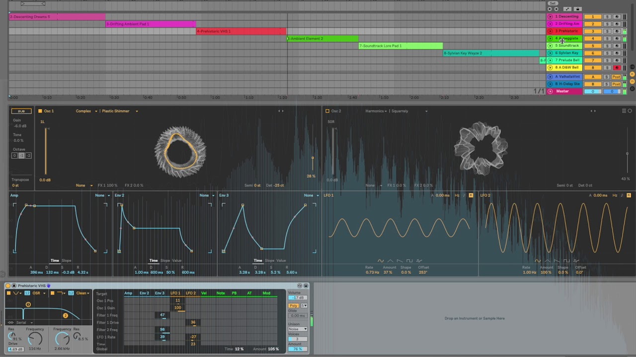
This is the new synth that comes with Ableton Live 10. In this video I play some random patches from the factory library to show the unique character of this synth. Many may compare this to the excellent Xfer Serum synth, but this one has a dirtier and more organic character.
...
obtuse spruce
man - the SAMD core has major bugs w.r.t. analogWriteResolution
stuck coral
The core software or the hardware peripheral?
obtuse spruce
the core software - Adafruit's implemetnation for SAMD51 doesn't respect the resolution value in the PWM case
stuck coral
Oh, awesome catch!
obtuse spruce
And... it defaults the resolution setting to 12 for SAMD51... which is bizarre, since I think it should default to 8
stuck coral
Hm, is there another platform like the SAM21 that defaults to 12? I wouldnt think so but never know
obtuse spruce
Well, that same core defaults to 8 when compiled for SAMD21!
AND I just noticed that it has the opposite flaw for SAMD21: It doesn't respect the resolution for the DAC
stuck coral
Hm, interesting. Adafruit should pay you to audit the core files 😜
 ornate nexus
does anybody know if i can put machine learning onto arduino mega
stuck coral
You could do some basic ML but it would be quite limited and slow
stuck coral
Nope
ornate nexus
so then i would use only IDE?
stuck coral
Maybe someone has some libraries to help you, but you are correct in you wouldnt have a full framework to use for implementation
obtuse spruce

GitHub
The implementation in wiring_analog.c is inconsistent w.r.t. the write resolution value (_writeResolution): When writing to a DAC on a non-SAMD51 platform, the resolution is ignored, and the value ...
ornate nexus
ok
obtuse spruce
Filed - and "woohoo" I got issue #256
ornate nexus
ill search
stuck coral
If you need to do any ML @ornate nexus I would point you in the direction of the SAMD51, it has support for tensorflow lite and Adafruit makes a board in the MEGA form factor
ornate nexus
are you saying i use both mega and that
stuck coral
No
ornate nexus
just the SAMD51
stuck coral
Correct, it has a ARM core, it runs a lot faster, it has a lot more memory, and access to a SIMD instruction set
ornate nexus
do you think i could attach the pca9685 to it cause i can run servos
i was having trouble programming that using the rpi
stuck coral
Yes, it has the ability to have many I2C interfaces which is what the pca9685 uses to communicate
ornate nexus
ok thank you so much
 bold island
Hey there, not sure if this is the right place, i need help with my project. I am using multiple PZEM004Tv3 power meters to watch over energy. As they are too many i am running out of heap due to global variables amount. I could save the variables in progmem but i dotn know the right syntax. Can anyone help me create working example? thank you; here my current simplified code https://pastebin.com/raw/r0JChZZe
 wraith current
@bold island show us your serial output. Doesn't seem like you should be running out of heap.
 midnight pike
Hello, I am using an Arduino MKR Wifi 1010 together with the MKR ENV Shield and a soil moisture sensor and want to send the created values from the sensors to ThingSpeak.
I am not sure what I am doing wrong, cause the board connects to the wifi but doesn’t send the data to ThingSpeak. Can somebody tell me where I am wrong?
https://pastebin.com/6A2Xk8pm
Pastebin
Pastebin.com is the number one paste tool since 2002. Pastebin is a website where you can store text online for a set period of time.
elder hare
@lone ferry hi 🙂 i just wanted to tell you that i tried that step thing you gave me worked 🙂 it is animating fine now ❤️ 🙂 ty for that
lone ferry
Awesome 🙂
elder hare
so im getting this error expression must be a modifiable lvalue
This is MySocket.h
//====================================================================================================================== //
// MYSOCKET
//====================================================================================================================== //
#ifndef MYSOCKET_H
#define MYSOCKET_H

#include <WebSocketsServer.h>
#include <ArduinoJson.h>
#include "Config.h"
#include "MyFastLEDMatrix.h"

WebSocketsServer webSocket = WebSocketsServer(SocketPort);

//====================================================================================================================== //
// CLASS - MYSOCKET
//====================================================================================================================== //
class MySocketClass {

public:
  static void webSocketEvent(uint8_t num, WStype_t type, uint8_t *payload, size_t length) {

    IPAddress ip = webSocket.remoteIP(num);                                  // Get Remote Client IP

    StaticJsonDocument<SocketJson> doc;                                      // Init Static Json Document
    deserializeJson(doc, payload);                                           // Deserialize Incoming Json

    if (doc["pixArt"]) {
      char *data = (char*) malloc(strlen(doc["pixArt"]));
      strcpy(data, doc["pixArt"]);
      pixelArt = data;
      Serial.println(data);
    }

    switch (type){
    case WStype_DISCONNECTED:
    Serial.printf("[SOCKET] [%u] Disconnected!\n", num);
    break;
    case WStype_CONNECTED:
    Serial.printf("[SOCKET] [%u] Connected from %d.%d.%d.%d url: %s\n", num, ip[0], ip[1], ip[2], ip[3], payload);
    break;
    default: break;
    }
  }

  void loop(){
    webSocket.loop();
  }

  void begin(){
    webSocket.begin();
    webSocket.onEvent(webSocketEvent);
  }
};

MySocketClass *MySocket;

#endif
This is the error line pixelArt = data;
now the variable pixelArt is in the MyFastLEDMatrix.h that i have included in the MySocket.h as you can see at the top
and pixelArt is setup like this
unsigned long pixelArt[] = { };
@lone ferry you have any idea?
lone ferry
Well, data and pixelArt have different datatypes, for one.
elder hare
well if i do it like this
    if (doc["pixArt"]) {
      pixelArt = doc["pixArt"];
    }
i get
expression must be a modifiable lvalue
incompatible types in assignment of 'ArduinoJson6152_0000010::enable_if<true, ArduinoJson6152_0000010::MemberProxy<ArduinoJson6152_0000010::JsonDocument&, const char*> >::type {aka ArduinoJson6152_0000010::MemberProxy<ArduinoJson6152_0000010::JsonDocument&, const char*>}' to 'long unsigned int [0]'
Well, that's what I said: these two variables have different datatypes. You can't put a square peg in a round hole.
I don't know that you're attempting to do with pixelArt but it should be a char * if you want the above code to work.
Also this line, char *data = (char*) malloc(strlen(doc["pixArt"])); needs to be char *data = (char*) malloc(strlen(doc["pixArt"]) + 1);. You need an extra character to store the null-terminator at the end of the string.
elder hare
im transmitting this from python
to the json doc[pixelArt]
then i need to store this in the unsigned long pixelArt[] = { };
it's a hex image
lone ferry
doc["pixArt"] is a string that contains text. You need to convert this text to numbers first, before you can put them into your unsigned long pixelArt[] variable.
If you know that each image will have the same size, you should first write unsigned long pixelArt[H * W] = { 0 }; where H and W are the height and width. Right now it's an empty array that you can't actually put any values into.
elder hare
the image is 16x16 so 256
lone ferry
Then you need to write some code that steps through the string from doc["pixArt]" to read 256 numbers.
elder hare
realy? 😮 and then also place ","?
lone ferry
Not sure what you mean with that...
elder hare
Googling...
 errant geode
Does anyone know how long wires i can attach to ds18b20 temperature sensor and mh-rd raindrops sensor?
 quartz furnace
@errant geode Clarifying .. are you asking the max length of a cable wire for those items ?
quartz furnace
ds18b20 uses “1-wire bus” ... on a google search it appears that type of communication can go 100 meters
The MJ-rd has a digital pin?
If you think distance is an issue .. is it possible to power a ESP8266 or ESP32 outside and gather the readings and post them ? I’ve successfully used the Ds18b20 with a 8266 and used it with Adafruit IO
obtuse spruce
@elder hare - if you control the python code that transmits that - you'll make your job on the devBoard much much easier if you transmit that array as an array in the json doc, rather than as a string.
Because then on the devBoard you have something like:
uint32_t pixelArt[16*16];
...
    if (doc["pixArt"]) {
      JsonArray src = doc["pixArt"].as<JsonArray>();
      uint32_t *dst = pixelArt;
      for (JsonVariant p : src)
        *dst++ = p.as<unsigned long>();
    }
assuming you're using the ArduinoJson library
lone ferry
@obtuse spruce I think the reason he has formatted the data as 0xff..., 0xff..., etc is a misunderstanding between what data looks like in source code and what it looks like in memory. So he's sending his data as C++ source code to a running Arduino program.
obtuse spruce
I just didn't want him to go down the road of parsing that string on the Arduino side - it will be much easier to learn how to send it - as data - from the Python side.
north stream
Normally I'd use Firmata for something like that, but it's a whole 'nother can of worms.
obtuse spruce
I've been observing a few common coding misconceptions here and am thinking about doing some form of workshop or coding dojo for newcomers to coding, specifically for those coming to it for MCU projects. I used to lead a coding dojo at Google... but all day and in-person... so I'm going to have to think about how.
elder hare
i know this is arduino but this is how it's done in python side befor i send it
    def convertImage(self):
        img = Image.open(self.imagePath).convert("RGB")
        img_array = img.tobytes().hex()
        row = []
        for i, batch in enumerate(batches(img_array, 6)):
            row.append(f"0x{''.join(batch)}")
        self.final = ','.join(row)**
Open to ideas.
elder hare
and then i send it with
self.socket.sendMessage('pixArt', self.final)

    def sendMessage(self, bName, bValue):
        self.client.sendTextMessage('{"' + bName + '": "' + str(bValue) + '"}')
wait - that's in Python? If you are sending Json - then by all means use the Python json library!
But sendMessage tells us nothing - because it can do anything.... where did the bValue that is that large string come from? It is in that place that you shouldn't be doing the work to generate a string of hex formatted numbers (because you'll just have to parse it on the Arduino) - but instead letting Json encode an actual array of numbers.
what is the source of this bitmap? a file? generated? static?
oh - sorry, missed first message there
reading....
are you using PIL or Pillow in Python.... let me know so I can give you the right code fragments
elder hare
PIL
obtuse spruce
okay - so first of all, you need just the list of pixel values, right?
  def convertImage(self):
    img = Image.open(self.imagePath).convert("RGB")
    self.final = img.getdata()
you might have to make that last line list(img.getdata()) - but try it without first.
obtuse spruce
now, to send it you need:
import json
...
  def sendMessage(self, bName, bValue):
    self.client.sendTextMessage(json.dumps({bName: bValue})
So, in the first block - we simply ask the img to generate a list of pixel values - no need to do dive into its internals with tobytes().
In the second block we build a small dict - and have the json library encode it for us - don't build json by hand if you don't have to.
elder hare
hmm when i print that out i get
<ImagingCore object at 0x115DFEB0>
Correct or?
obtuse spruce
could be - PIL tries to not copy data around all that much - so we don't know if that object "will do the right thing" - but sure, add the list( ) wrapper - and you should see a list of numbers
elder hare
trying now
there is something yes
[(102, 204, 204), (102, 204, 204), (102, 204, 204), (102, 204, 204),
oh - so, a list of tuples....
hrm... okay, close... let's fix it to be the list of RGB values you want:
self.final = [ r << 16 | g << 8 | b for (r, g, b) in img.getdata() ]
(again, you may need the list(img.getdata()) - but in this context I doubt it.
elder hare
this is what i got
[6737100, 6737100, 6737100, 6737100, 6737100, 6737100, 0, 0, 0, 0, 6737100, 6737100, 6737100, 6737100, 6737100, 6737100,
good! Those are your pixels, yes?
lone ferry
Verify that len(self.final) is 256.
elder hare
confirmed 256
obtuse spruce
good point, @lone ferry - though we should make the receiving side be robust so that it doesn't die a horrible death if the python code sends more
That python construct, btw, is called a list comprehension - but basically it lets you easily transform a list from one thing into another - by build a list from a for loop over another. It is not only more concise than writing out the for loop - it is cleaner code, because there is less chance to mess up the loop.
elder hare
noted!
obtuse spruce
So now you have a list of integers that are the pixel values - and we can just let the Python json library encode that as json - send that - and let the ArduinoJson library decode that.... and so all along the way you don't need to do any explicit parsing or encoding/decoding of numbers or hex strings - you are dealing with just data - which is what you want - the libraries will be better at that stuff that we are - mostly because they've coded for all the corner cases and error situations (we hope!)
elder hare
but can i use the numbers in the FastLED lib to display the image on the 16x16 i have? i thought they needed to be hex :S
obtuse spruce
numbers don't have a base when they are numbers
they aren't hex or decimal ... they are just numbers (okay, actually, in memory they are stored as binary - but in code, when you treat them as uint32_t they are just numbers)
they only are "hex" or "dec" when you convert them to strings and send them as printable text.
in FastLED, the values in your led array are just uint32t values - exactly as you are transmitting.
leds[i] = pixelArt[j];
this will work because both sides are just uint32_t - a 32-bit number.
to make this more clear:
uint32_t x;
x = 42;    // sets value to the number 42;
x = 0x2a;  // same value!
x = "42";  // fails because you can't assign a string to number
x = "0x2a"; // same failure, but a _different_ string
@obtuse spruce Mr Zero, are you a teacher in real life? 😄 i love when you explain things 😄
obtuse spruce
Well, I was a SW eng. for 30+ years - and have lead many a team with junior members - I did a lot of teaching. At Google I was also one of the instructors for "coding dojo".
elder hare
maybe im missing something! but at the arduino side when i do this
    const size_t CAPACITY = JSON_ARRAY_SIZE(256);

    StaticJsonDocument<CAPACITY> doc;
    deserializeJson(doc, payload);

    JsonArray array = doc["pixArt"].as<JsonArray>();
      for(JsonVariant v : array) {
        Serial.println(v.as<uint32_t>());
      }
it prints out
6737100
6737100
6737100
6737100
6737100
6737100
0
0
0

and so on
but how do i copy the json array into here?
unsigned long pixelArt[256] = { }
Scroll up a bit, @elder hare to the code that was posted earlier.
obtuse spruce
but in short: YAY! You're getting your numbers from one end to the other - and they are arriving as we are expecting.
uint32_t pixelArt[16*16];
...
    if (doc["pixArt"]) {
      JsonArray src = doc["pixArt"].as<JsonArray>();
      int i = 0;
      for (JsonVariant p : src)
        if (i >= 256) break; // just to be safe!
        pixelArt[i++] = p.as<uint32_t>();
    }
this version has a safety check
elder hare
oh can you actualy do pixelArt[16*16] thought you always had to write the "total number" like pixelArt[256]
lone ferry
16*16 is a constant value so the compiler will turn that into 256 automatically.
lone ferry
Because @obtuse spruce committed a grave sin and forgot the { } brackets around the for loop.
😉
elder hare
i see it now yea xD
wait what :S
it still says that 'p' was not declared in this scope
lone ferry
What does your code look like now?
elder hare
    if (doc["pixArt"]) {
      JsonArray src = doc["pixArt"].as<JsonArray>();
      int i = 0;
      for (JsonVariant p : src) {
        if (i >= 256) break; // just to be safe!
        pixelArt[i++] = p.as<uint32_t>();
      }
    }
And what line is the error on?
elder hare
pixelArt[i++] = p.as<uint32_t>();
lone ferry
You're sure it says JsonVariant p in the for statement and not JsonVariant v?
elder hare
yupp im sure :S
lone ferry
Well, I don't see any issues with that code snippet above. It could be there is something wrong elsewhere in your code (missing bracket or one too much).
elder hare
there as a e inside the code -.- maybe a typo from me -.-
but now that my pixelArt array became a uint32_t the rest of the code broke as everything was based on unsigned long
lone ferry
Try pixelArt[i++] = p.as<unsigned long>();
lone ferry
🙂
bold island
@wraith current i provided just example sketch; i am running out of heap with 16 devices because each take 2.8kbyte, thats why i need another way of definition, any idea ?
obtuse spruce
@bold island - I looked at that code, and the heap allocation is because each instance of PZEM004Tv30 allocates an instance of SoftwareSerial on the stack.
Since I'm guessing they are all sitting on the same serial pair of lines (as your three in your example are) - means you are createing 16 SoftwareSerial objects for the same set of pins.
I'm pretty sure that isn't going to work.
or at the very least it is tenuous
bold island
@obtuse spruce actually i am using HardSerial; 5 on each gpio pair
obtuse spruce
okay, so you are are using the PZEM004Tz30(Serial, addr) constructors, not the ones with two pins, right?
bold island
@obtuse spruce yes correct
obtuse spruce
okay - well, the code of PZEM004Tv30 doesn't otherwise allocate heap memory - and neither does any of the code that you showed in the example. So we need to look elsewhere for what is using the heap.
bold island
each instance of pzem takes about 2800 bytes if defined in global variable
16 works fine for me; 17 - crash
obtuse spruce
so you are running out of heap or global?
bold island
out of heap, i decoded as this error Exception 29: StoreProhibited: A store referenced a page mapped with an attribute that does not permit stores
obtuse spruce
Hmmmm.... PZEM004Tv30 shouldn't take more the ~50 bytes each.
Did you get 2800 from a sizeof on it?
This is the library you're using, right? https://github.com/mandulaj/PZEM-004T-v30
GitHub
Arduino library for the Updated PZEM-004T v3.0 Power and Energy meter - mandulaj/PZEM-004T-v30
bold island
yes thats the library; i am calculating free heap by Serial.println(ESP.getFreeHeap(),DEC);
obtuse spruce
okay - I'm wondering what is causing that - perhaps you'd be willing to put your whole sketch in a pastebin?
obtuse spruce
does the FreeHEAP values decrease during a single pass through loop()?
bold island
09:18:58.073 -> RSSI:-64
09:18:58.073 -> FreeHEAP:3192
09:19:00.073 ->
09:19:03.073 ->
09:19:03.393 -> FreeHEAP:2520
not really
obtuse spruce
Ah ha!
You are using the SoftwareSerial instances:
PZEM004Tv30 pzem1(D5, D6, 0x01);
PZEM004Tv30 pzem2(D5, D6, 0x02);
PZEM004Tv30 pzem7(D5, D6, 0x07);
PZEM004Tv30 pzem8(D5, D6, 0x08);
PZEM004Tv30 pzem13(D5, D6, 0x0d);
PZEM004Tv30 pzem14(D5, D6, 0x0e);
//PZEM004Tv30 pzem19(D5, D6, 0x13);
These are EACH allocating a SoftwareSerial object on the heap - and furthermore, each is running those pins via a software serial implementation.
bold island
hm... i thought adding addr makes them hardserial
obtuse spruce
So you have 6 SoftwareSerial instances each driving the pins.
NOPE
Addr isn't a feature of serial interfaces - (only I2C)
bold island
aw thats news for me 🙂 how to modify the code so it run with more instances then ?
obtuse spruce
yes, the addr in PZEM004Tv30 is a feature of the protocol to that device
So, you need to use the other constructor:
PZEM004Tv30::PZEM004Tv30(HardwareSerial* port, uint8_t addr)
If you are using all hardware serial interfaces
just pass the appropriate Serial object
bold island
can you please give me real example code for replace "PZEM004Tv30 pzem1(D5, D6, 0x01);" ; sorry i am weak in C mainly bash;
obtuse spruce
PZEM004Tv30 pzem1(Serial2, 0x01)
But you have to know which SerialX instances exist for your board, and which pins they are on - etc.....
What board are you using?
bold island
D1 mini
obtuse spruce

RasPiO Store
Wemos D1 mini is like a "little Arduino with wifi" for a great price. It's based around the ESP8266, has one analogue port and 11 digital ports. It's programmed via micro-USB (or remote flash via wifi). You can use it with the Arduino IDE, micropython or NodeMCU.
It runs from ...
bold island
yes
if you mean connect all devices to single pairs of pins it wont work, there is too much power draw from the pzem and 400mA voltage regulator on d1 mini isnt sufficient.
what i observed is that it always request all devices and only those with correct address reply, so it means powering all at same time
obtuse spruce
well, none of the documents for that board are on line - but I really doubt it has three hardware serial instances,
bold island
thats why i split to 3 pairs of gpio pins now powering jsut one third of it

Diagram Pin Pin Function ESP-8266 Pin TX TXD TXD RX RXD RXD A0 Analog input, max 3.3V input A0 D0 IO GPIO16 D1 IO, SCL GPIO5 D2 IO, SDA GPIO4 D3 IO,10k Pull-up GPIO0 D4 IO, 10k pull-up, BUILTIN_LED GP
obtuse spruce
Okay - Looks to me like it has only one Serial hardware interface
and it is on TX/RX pins.
bold island
right
obtuse spruce
So you'd have to use the SoftwareSerial implementation - which emulates serial hardware by twiddling the I/O lines in software --- which is probably okay .... BUT
and it is a big BUT
The problem is that the PZEM004Tv30 library you are using doesn't support multiple sensors using the same SoftwareSerial interface.
It is sad, 'cause it is like a five line addition to the library to make it work.
bold island
its working without issues one week already, just cant add 4 more devices to monitor all due to mem
obtuse spruce
It works - but you are courting failure: Each instance is using it's own bit-banging software serial instance - allocated on the heap - and that is a recipe for "bad things" (shoudl, for example, any of those ever try to use the pins at the same time...)
And in any case, even if you accept that hack (using multiple SoftwareSerial objects on the same pins) the PZEM004Tv30 library doesn't offer any alternative to allocating them on the heap.
SO - in short, that library is holding you back.
bold island
i understand; but still there is a possibility to reduce the global variable size maybe by progmem ?
bold island
which one?
obtuse spruce
You can use 1 PZEM004Tv30 object for each serial chain - so, in your case, you'd have only 3.
Then, before any operation you want to do, you need to first call init(addr)
that call will change the address the instance talks to
(don't call setAddress() - that call changes the address the device uses!!!)
Hold on - let me give you an example...
bold island
that would be great; thanx
obtuse spruce
Okay, so here is the version that most closely matches how you wrote things:
PZEM004Tv30 pzemA(D5, D6);
  // units 1, 2, 7, 8, 13, 14

PZEM004Tv30 pzemB(D3, D4);
  // units 3, 4, 9, 10, 15, 16

PZEM004Tv30 pzemC(D1, D2);
  // units 5, 6, 11, 12, 17, 18


...


void current() {
    pzemA.init(1);   float current1    = pzemA.current();  Blynk.virtualWrite(V2,  current1);
    pzemA.init(2);   float current2    = pzemA.current();  Blynk.virtualWrite(V8,  current2);
    pzemB.init(3);   float current3    = pzemB.current();  Blynk.virtualWrite(V14, current3);
    pzemB.init(4);   float current4    = pzemB.current();  Blynk.virtualWrite(V20, current4);
    pzemC.init(5);   float current5    = pzemC.current();  Blynk.virtualWrite(V26, current5);
    pzemC.init(6);   float current6    = pzemC.current();  Blynk.virtualWrite(V32, current6);
    pzemA.init(7);   float current7    = pzemA.current();  Blynk.virtualWrite(V38, current7);
    pzemA.init(8);   float current8    = pzemA.current();  Blynk.virtualWrite(V44, current8);
    pzemB.init(9);   float current9    = pzemB.current();  Blynk.virtualWrite(V50, current9);
    pzemB.init(10);  float current10   = pzemB.current(); Blynk.virtualWrite(V56, current10);
    pzemC.init(11);  float current11   = pzemC.current(); Blynk.virtualWrite(V62, current11);
    pzemC.init(12);  float current12   = pzemC.current(); Blynk.virtualWrite(V68, current12);
    pzemA.init(13);  float current13   = pzemA.current(); Blynk.virtualWrite(V74, current13);
    pzemA.init(14);  float current14   = pzemA.current(); Blynk.virtualWrite(V80, current14);
    pzemB.init(15);  float current15   = pzemB.current(); Blynk.virtualWrite(V86, current15);
    pzemB.init(16);  float current16   = pzemB.current(); Blynk.virtualWrite(V92, current16);
}
But, I'd never write it like that... let me clean it up....
bold island
how u calling the addr here ?
i have one esp-wroom-32 here maybe it is better idea to use this chip
has more memory
obtuse spruce
oh sorry - just give 0 as the adder
PZEM004Tv30 pzemA(D5, D6, 0);
  // units 1, 2, 7, 8, 13, 14

PZEM004Tv30 pzemB(D3, D4, 0);
  // units 3, 4, 9, 10, 15, 16

PZEM004Tv30 pzemC(D1, D2, 0);
  // units 5, 6, 11, 12, 17, 18
it doesn't matter because you are going to set the address each time you use the object (using init())
So, the following is how I'd write current()
float getCurrent(PZEM004Tv30& pzem, uint8_t addr) {
  pzem.init(addr);
  return pzem.current();
}

void current() {
    Blynk.virtualWrite(V2,  getCurrent(pzemA, 1));
    Blynk.virtualWrite(V8,  getCurrent(pzemA, 2));
    Blynk.virtualWrite(V14, getCurrent(pzemB, 3));
    Blynk.virtualWrite(V20, getCurrent(pzemB, 4));
    Blynk.virtualWrite(V26, getCurrent(pzemC, 5));
    Blynk.virtualWrite(V32, getCurrent(pzemC, 6));
    Blynk.virtualWrite(V38, getCurrent(pzemA, 7));
    Blynk.virtualWrite(V44, getCurrent(pzemA, 8));
    Blynk.virtualWrite(V50, getCurrent(pzemB, 9));
    Blynk.virtualWrite(V56, getCurrent(pzemB, 10));
    Blynk.virtualWrite(V62, getCurrent(pzemC, 11));
    Blynk.virtualWrite(V68, getCurrent(pzemC, 12));
    Blynk.virtualWrite(V74, getCurrent(pzemA, 13));
    Blynk.virtualWrite(V80, getCurrent(pzemA, 14));
    Blynk.virtualWrite(V86, getCurrent(pzemB, 15));
    Blynk.virtualWrite(V92, getCurrent(pzemB, 16));
}
Is that more clear?
Using a chip with more memory isn't going really fix things - you'll still be doing the thing of driving the pins from multiple SoftwareSerial instances - which isn't great
bold island
so if i understand correctly before we have each pzem hard-defined and now we define just once float and addr will be changing ?
obtuse spruce
before you had one pzem object for each sensor .... but really the pzem object should be defined once per serial port. That you can have multiple sensors all listening and accessing the same serial line pair is a bit "uncommon" - sort of an ad hoc I2C like scheme..... the sensor determines it should respond because each command has an "address" embedded in it - (again, part of the protocol, not a feature of Serial interfaces in general) ---- and the pzem object just remembers an address that it inserts in each command it issues.
SO - now we have one pzem object per serial chain - and before we ask it to issue a command and report the result, we tell the pzem object, via init() which address we'd like it to put in the command -- and then we have it issue the command.
If you think this feels a bit awkward, you're right. The PZEM-004T-v30 library didn't anticipate being used with multiple sensors on a single, software serial line.
But, fortunately you can poke it to do the right thing.
My wrapper function getCurrent() just bundles up the two calls so that they are coded once, and out of the way.
bold island
let me try to compile if it works
getting exit status 1
within this context
on pzem.init(addr);
obtuse spruce
did you change ALL the other functions as well? you'll need wrappers for voltage, power, etc...
OH DANG It
that library is a mess
bold island
i testing only one function now https://pastebin.com/1ad2U8EH
Pastebin
Pastebin.com is the number one paste tool since 2002. Pastebin is a website where you can store text online for a set period of time.
obtuse spruce
init() is private
sigh
you're sunk unless you're willing to fork that library and add the missing constructor it needs.
bold island
unfortunately that is far beyond my knowledge
obtuse spruce
then there is nothing you can do --- but the fork of that library would be VERY VERY VERY VERY simple -
but you do need to be comfortable with C++
bold island
i am linux guy; so basic bash scripting is fine for me but c++ is only very little; close to nothing
so you see no easy solution there ?
obtuse spruce
No - the library didn't expect to support multiple sensors on the same serial line. It doesn't support what you are trying to do. It sort of kind of works - but that is a happy accident - and as you see it isn't heap friendly.
The library is 99.9% of the way there, however - all it needs is one more constructor - that lets it use a Serial object that you pass in.
bold island
i understand; i will send a message to the library developer for fix that i think it will be the best way
thank you very much for your time you spent with me explaining things, really appreciate what you doing
obtuse spruce
welcome
last thing
tell him you're trying to do something like this:
SoftwareSerial s56(D5, D6);
SoftwareSerial s34(D3, D4);
SoftwareSerial s12(D1, D2);

PZEM004Tv30 pzem1(s56, 0x01);
PZEM004Tv30 pzem2(s56, 0x02);
PZEM004Tv30 pzem3(s34, 0x03);
PZEM004Tv30 pzem4(s34, 0x04);
PZEM004Tv30 pzem5(s12, 0x05);
PZEM004Tv30 pzem6(s12, 0x06);
PZEM004Tv30 pzem7(s56, 0x07);
PZEM004Tv30 pzem8(s56, 0x08);
PZEM004Tv30 pzem9(s34, 0x09);
PZEM004Tv30 pzem10(s34, 0x0a);
PZEM004Tv30 pzem11(s12, 0x0b);
PZEM004Tv30 pzem12(s12, 0x0c);
PZEM004Tv30 pzem13(s56, 0x0d);
PZEM004Tv30 pzem14(s56, 0x0e);
PZEM004Tv30 pzem15(s34, 0x0f);
PZEM004Tv30 pzem16(s34, 0x10);
PZEM004Tv30 pzem17(s12, 0x11);
PZEM004Tv30 pzem18(s12, 0x12);
PZEM004Tv30 pzem19(s56, 0x13);
he needs to provide you with a constructor like so:
PZEM004Tv30(Serial* port, uint8_t addr=PZEM_DEFAULT_ADDR);
i think this is the same thing what i need, someone already requested in the library git https://github.com/mandulaj/PZEM-004T-v30/issues/19#issuecomment-670906463
GitHub
I follow the same initialization, as you said. But it only returns the last PZEM connected. here's my code. '#include <PZEM004Tv30.h> /* Use software serial for the PZ...
obtuse spruce
yes - and it is clear that the library owner is missing the problem - in their Feb 3rd response they make the same mistake
There are several other issues filed with similar concerns - and frankly it is clear no one seems to have a clear method for handling this.
bold island
so more users have same issue, i will try with array https://github.com/mandulaj/PZEM-004T-v30/issues/29#issuecomment-671593374
GitHub
Dear good day, Appreciate your efforts, can you please update the library to use ip function to add multiple pzem v3 devices in the same code. Thanks
obtuse spruce
The array won't make any difference
each instance of PZEM004Tv30 constructed with pin numbers is going to allocate another SoftwareSerial on the heap - each taking 2800 or so bytes - and each trying to control the same pins.
bold island
ah yes u right
obtuse spruce
Fundimentally the library isn't written to handle multiple devices on the same serial.
okay - hold on
I'm going to fork the dang library!
bold island
ok
obtuse spruce
oh man - it won't even compile.
sorry- I thought it would be quick, but it is full of assumptions about the board one is using.
and I'm headed out now.
bold island
no problem, thanx for trying
wraith current
@bold island can you use local instantiated variable instead of global. It might make it slower to call the constructor everytime for every read but you might not even notice.
bold island
@wraith current can you please show me some example code how to do it?
wraith current
@bold island didn't you mention using an array or something before ? I'm not sure if it will work. did you ever post your entire sketch ?
bold island
yes i posted the full sketch, it is here https://pastebin.com/raw/aVnbKh93
i tested defining global variables as array but it didnt reduce the heap at all
wraith current
yeah. the array would hold the differing addresses for each SoftSerial. So you would go through the array and on each iteration, create the pzem object, use it, then it will be destroyed at the end of the iteration.
let me write a small example
bold island
thanx for help
wraith current
float voltage1    = pzem.voltage();  Blynk.virtualWrite(V1,  voltage1);
PZEM004Tv30 pzem(D5, D6, 0x02);
float voltage2    = pzem.voltage();  Blynk.virtualWrite(V2,  voltage2);
so the pzem object should be released from memory on the second instantiation.
bold island
u mean define this in void loop?
wraith current
it might not need to be in a loop actually. as long as you make sure that the memory is being freed. I'm not entirely sure if you need to explicity delete the object.
bold island
sorry i dont understand; where i should insert this code?
wraith current
something like delete pzem; might do it.
that code just demonstrates a possible workaround. You'd need to rearrange all your code so that the location where call the line like : PZEM004Tv30 pzem1(D5, D6, 0x01); PZEM004Tv30 pzem2(D5, D6, 0x02); PZEM004Tv30 pzem3(D3, D4, 0x03);
are not in global scope, but in local scope (ie. in the main loop.)
bold island
yes i understand your point, define pzem1 - use it delete; and so on until N
but i think that pzem can only be defined in global
but let me try if it will compile
this code
#include <PZEM004Tv30.h>
#include <BlynkSimpleEsp8266.h>
void setup() {
Serial.begin(115200);
}
void loop() {
PZEM004Tv30 pzem1(D5, D6, 0x01); float voltage1 = pzem1.voltage(); Blynk.virtualWrite(V1, voltage1);
PZEM004Tv30 pzem2(D5, D6, 0x02); float voltage2 = pzem2.voltage(); Blynk.virtualWrite(V2, voltage2);
Serial.print("FreeHEAP:"); Serial.println(ESP.getFreeHeap(),DEC);
delay(50);
}
result in crash
11:41:41.575 -> ets Jan 8 2013,rst cause:2, boot mode:(3,6)
11:41:41.575 ->
11:41:41.575 -> load 0x4010f000, len 3584, room 16
11:41:41.575 -> tail 0
11:41:41.575 -> chksum 0xb0
11:41:41.575 -> csum 0xb0
11:41:41.575 -> v2843a5ac
11:41:41.575 -> ~ld
11:41:41.855 -> FreeHEAP:44320
11:41:42.135 -> FreeHEAP:38944
11:41:42.415 -> FreeHEAP:33568
11:41:42.655 -> FreeHEAP:28192
11:41:42.935 -> FreeHEAP:22816
11:41:43.175 -> FreeHEAP:17440
11:41:43.455 -> FreeHEAP:12064
11:41:43.735 -> FreeHEAP:6688
11:41:43.975 -> FreeHEAP:1312
11:41:44.255 -> FreeHEAP:1072
11:41:44.535 -> FreeHEAP:832
11:41:44.775 -> FreeHEAP:592
11:41:45.055 -> FreeHEAP:352
11:41:45.215 ->
11:41:45.215 -> --------------- CUT HERE FOR EXCEPTION DECODER ---------------
11:41:45.215 ->
11:41:45.215 -> Exception (29):
11:41:45.215 -> epc1=0x4000df64 epc2=0x00000000 epc3=0x00000000 excvaddr=0x00000000 depc=0x00000000
11:41:45.215 ->
11:41:45.215 -> >>>stack>>>
after the loop finish it doesnt release the memory for pzem data
wraith current
ok ,so then we probably need to explicityly release the memory. try adding
exit status 1
type 'class PZEM004Tv30' argument given to 'delete', expected pointer
wraith current
ok try delete &pzem1
bold island
Exception 3: LoadStoreError: Processor internal physical address or data error during load or store
obtuse spruce
no no - you can't delete an object created that way
wraith current
hmm. well, i'm just guessing at this point, but mzero is back to save uss
obtuse spruce
and you don't need to because it will be destructed when the loop function exits
BUT - this isn't going to solve this - because it means each and every time you create the pzem objects - they are going to create the SoftwareSerial objects - on the heap - and you are right back at square one
bold island
the mem is not freed up when loop finished, it always consume more and more mem until crash
11:41:41.855 -> FreeHEAP:44320
11:41:42.135 -> FreeHEAP:38944
11:41:42.415 -> FreeHEAP:33568
11:41:42.655 -> FreeHEAP:28192
11:41:42.935 -> FreeHEAP:22816
11:41:43.175 -> FreeHEAP:17440
11:41:43.455 -> FreeHEAP:12064
11:41:43.735 -> FreeHEAP:6688
11:41:43.975 -> FreeHEAP:1312
11:41:44.255 -> FreeHEAP:1072
11:41:44.535 -> FreeHEAP:832
11:41:44.775 -> FreeHEAP:592
11:41:45.055 -> FreeHEAP:352
wraith current
so it's all the library's fault and not much we can do to get around it ?
bold island
yes but if i could create 1-6 pzem, then delete and free mem, then 7-12 ... it coudl work maybe
obtuse spruce
That is probably because you are not calling Blynk.run() inside loop()
bold island
ok let me try
obtuse spruce
Okay - let's try this ---- if you really want to make this work - let me talk you through modifying the library (since it won't compile on my system as I don't have that Core for that board)
Are you game?
bold island
yes but as i said i am just a noob 🙂
obtuse spruce
Just going to be cut-n-paste job here
bold island
btw i tried to run blynk inside loop and still heap going down
obtuse spruce
Okay, edit PZEM004Tv30.h
bold island
ok i am there
obtuse spruce
change the section at line 62 to look like this:
#if defined(PZEM004_SOFTSERIAL)
    PZEM004Tv30(uint8_t receivePin, uint8_t transmitPin, uint8_t addr=PZEM_DEFAULT_ADDR);
    PZEM004Tv30(SoftwareSerial &port, uint8_t addr=PZEM_DEFAULT_ADDR);
#endif
you're adding a line there, just before the #endif
obtuse spruce
Now edit PZEM004T.cpp, about line 91, above the #endif there, add
#ifdef PZEM004_SOFTSERIAL
PZEM004Tv30::PZEM004Tv30(SoftwareSerial &port, uint8_t addr)
{
    port.begin(PZEM_BAUD_RATE);
    this->_serial = &port;
    this->_isSoft = false;
    init(addr);
}
Now recompile your sketch, to be sure that we haven't messed the library files up
bold island
should be like this?
#if defined(PZEM004_SOFTSERIAL)
PZEM004Tv30::PZEM004Tv30(uint8_t receivePin, uint8_t transmitPin, uint8_t addr)
{
SoftwareSerial *port = new SoftwareSerial(receivePin, transmitPin);
port->begin(PZEM_BAUD_RATE);
this->_serial = port;
this->_isSoft = true;
init(addr);
}
#ifdef PZEM004_SOFTSERIAL
PZEM004Tv30::PZEM004Tv30(SoftwareSerial &port, uint8_t addr)
{
port.begin(PZEM_BAUD_RATE);
this->_serial = &port;
this->_isSoft = false;
init(addr);
}
bold island
ok
#if defined(PZEM004_SOFTSERIAL)
PZEM004Tv30::PZEM004Tv30(uint8_t receivePin, uint8_t transmitPin, uint8_t addr)
{
SoftwareSerial *port = new SoftwareSerial(receivePin, transmitPin);
port->begin(PZEM_BAUD_RATE);
this->_serial = port;
this->_isSoft = true;
init(addr);
}
PZEM004Tv30::PZEM004Tv30(SoftwareSerial &port, uint8_t addr)
{
port.begin(PZEM_BAUD_RATE);
this->_serial = &port;
this->_isSoft = false;
init(addr);
}
obtuse spruce
correct
bold island
and now this code should work, right?
#include <PZEM004Tv30.h>
#include <ESP8266WiFi.h>
#include <BlynkSimpleEsp8266.h>
PZEM004Tv30 pzemA(D5, D6, 0);
// units 1, 2, 7, 8, 13, 14
PZEM004Tv30 pzemB(D3, D4, 0);
// units 3, 4, 9, 10, 15, 16
PZEM004Tv30 pzemC(D1, D2, 0);
// units 5, 6, 11, 12, 17, 18
float getCurrent(PZEM004Tv30& pzem, uint8_t addr) {
pzem.init(addr);
return pzem.current();
}
void setup() {
Serial.begin(115200);
}
void current() {
Blynk.virtualWrite(V2, getCurrent(pzemA, 1));
Blynk.virtualWrite(V8, getCurrent(pzemA, 2));
Blynk.virtualWrite(V14, getCurrent(pzemB, 3));
Blynk.virtualWrite(V20, getCurrent(pzemB, 4));
Blynk.virtualWrite(V26, getCurrent(pzemC, 5));
Blynk.virtualWrite(V32, getCurrent(pzemC, 6));
Blynk.virtualWrite(V38, getCurrent(pzemA, 7));
Blynk.virtualWrite(V44, getCurrent(pzemA, 8));
Blynk.virtualWrite(V50, getCurrent(pzemB, 9));
Blynk.virtualWrite(V56, getCurrent(pzemB, 10));
Blynk.virtualWrite(V62, getCurrent(pzemC, 11));
Blynk.virtualWrite(V68, getCurrent(pzemC, 12));
Blynk.virtualWrite(V74, getCurrent(pzemA, 13));
Blynk.virtualWrite(V80, getCurrent(pzemA, 14));
Blynk.virtualWrite(V86, getCurrent(pzemB, 15));
Blynk.virtualWrite(V92, getCurrent(pzemB, 16));
}
void loop() {
Blynk.run();
power(); current();
Serial.print("FreeHEAP:"); Serial.println(ESP.getFreeHeap(),DEC);
Serial.println();
delay(200);
}
obtuse spruce
No
your globals will be like this:
SoftwareSerial serial56(D5, D6);
SoftwareSerial serial34(D3, D4);
SoftwareSerial serial12(D1, D2);

PZEM004Tv30 pzem1(serial56, 0x01);
PZEM004Tv30 pzem2(serial56, 0x02);
PZEM004Tv30 pzem3(serial34, 0x03);
PZEM004Tv30 pzem4(serial34, 0x04);
PZEM004Tv30 pzem5(serial12, 0x05);
PZEM004Tv30 pzem6(serial12, 0x06);
PZEM004Tv30 pzem7(serial56, 0x07);
PZEM004Tv30 pzem8(serial56, 0x08);
PZEM004Tv30 pzem9(serial34, 0x09);
PZEM004Tv30 pzem10(serial34, 0x0a);
PZEM004Tv30 pzem11(serial12, 0x0b);
PZEM004Tv30 pzem12(serial12, 0x0c);
PZEM004Tv30 pzem13(serial56, 0x0d);
PZEM004Tv30 pzem14(serial56, 0x0e);
PZEM004Tv30 pzem15(serial34, 0x0f);
PZEM004Tv30 pzem16(serial34, 0x10);
//PZEM004Tv30 pzem17(serial12, 0x11);
//PZEM004Tv30 pzem18(serial12, 0x12);
//PZEM004Tv30 pzem19(serial56, 0x13);
So you are going to create three global serial objects - one for each of the three serial lines. Then create a pzem object for each unit - constructing it with the appropriate serial line, and address. In this way nothing will be allocated on the heap, and there will only 3 SoftwareSerial objects, not 16
bold island
ok trying now...
12:11:20.114 ->
12:11:20.434 -> FreeHEAP:38840
12:11:22.434 ->
12:11:25.434 ->
12:11:27.194 -> FreeHEAP:38336
12:11:29.194 ->
12:11:32.194 ->
12:11:33.954 -> FreeHEAP:38336
12:11:35.954 ->
wow
bold island
i unrem the 3 remaining pzem and heap still same
obtuse spruce
yes - the heap isn't being used at all
because nothing is being dynamically allocated (at least as far as pzem is concerned... Blynk I have no idea about)
bold island
ouh man thats great, how i can thank you???
obtuse spruce
submit a really good issue with the original library!
bold island
i will do it today in your name
let me connect it to the meters if it acually still works
obtuse spruce
okay - I see on possible issue..... and I know how to fix it....
depending on the board you are on... it might not quite work... but we can fix it for all boards!
instead of adding the new constructor, we're going to replace the one that is there
bold island
it works for my board!
bold island
i spent like a week trying to find solution
obtuse spruce
are you getting all values from all senosrs?
bold island
yes i do
obtuse spruce
🙌
bold island
creating github issue now
obtuse spruce
well - that library is poorly built in that it doesn't really support the way those sensors are designed to be used (multiple sensors on a single serial pair) - I will note that that library is a fork of an earlier one that only did hardware serial ports - and didn't have this issue - that is, the hardware serial port version does work correctly for multiple sensors
bold island
yes its fork of this one https://github.com/olehs/PZEM004T

GitHub
Arduino communication library for Peacefair PZEM-004T Energy monitor - olehs/PZEM004T
obtuse spruce
The key mistake is that it is totally the wrong design decision for the library to createing SoftwareSerial port objects -- the user should (must) do that.
bold island
that was for old sensor v1
obtuse spruce
and - only HardwareSerial I think
bold island
maybe i didnt check that
@obtuse spruce issue posted https://github.com/mandulaj/PZEM-004T-v30/issues/35 ; once again thank you very much for your time
GitHub
Hi there, i worked on a project to monitor multiple breakers using this library + wemos d1 mini, but came into some issues. First it was powering them via internal voltage regulator which was solve...
obtuse spruce
you're welcome!
 odd willow
hello! I bought a chinese D1 wifi but does anyone know a good tutorial for the mac to get it working. It seems I can't get it working without one. Thank you!
quartz furnace
D1..... a WeMos D1 ?
elder hare
in Visual Studio if i install a older library version and then install a newer version, does visual studio delete the old one or how does that work?
odd willow
D1..... a WeMos D1 ?
@quartz furnace this one:
quartz furnace
Ahhh, nice , so then this ?
https://www.google.com/amp/s/rjdlee.com/getting-started-with-wemos-d1-on-mac-osx/amp/
@odd willow

Richard Lee
It took me way too long to get started with the WeMos D1 R2 board, partly
because mine is an eBay knockoff.
Getting Started
- Download and install the Arduino IDE (just called Arduino):
https://www.arduino.cc/en/Main/Software
[https://web.archive.org/web/2018082604...
 jagged void
https://learn.adafruit.com/adafruit-io-air-quality-monitor so I’ve been doing this project now twice because when I went to upload the code the error says that it can’t the middle sensor, twice now.

Adafruit Learning System
Build an internet-enabled environmental monitor to see what's in the air you breathe using Arduino or CircuitPython
Any help will be appreciated
safe halo
im trying to load a Latitude and Longitude from a JSON file but when I do i only copies up to 2 decimal places..
  "Latitude": 52.30979,
  "Longitude": 0.502071,
however when they read them in they come out as
52.3100000
0.5000000
I have tried double and Float
odd fjord
how are they being read and displayed? -- post the code that is showing you the rounded results
safe halo
Serial Print doesnt print more than 2 decimal places by default.. that was the issue..
Now I need to figure out why my Post is truncating the values as well
      String postData = "Serial=" + (String)SerialNumber + "&" +
                        "Latitude=" +  Latitude + "&" +
                        "Longitude=" +  Longitude + "&" +
                        "DateTime=" + CurrentTideTime + "&" +
                        "Value=" + CurrentTideValue + "&" +
                        "Units=";
results in Serial=4011914360&Latitude=52.31&Longitude=0.50&DateTime=21/08/20,15:18:39&Value=4.76&Units=m
obtuse spruce
@jagged void have you used a multimeter to check that it is all wired correctly?
@safe halo - the default number of places for String's float conversion is 2 - but you can be explicit. Replace Latitude with String(Latitude, 6)
 thorn relic
Trying to decide if I should use a Teensy or a Arduino Micro 32U4 for my USB joystick
OR should I be looking at these newfangled XIAO board
I think I should purely based on it being USB-C 😄
quartz furnace
@thorn relic is wireless a possibility?
https://learn.adafruit.com/atarifruit-2600-joystick/programming-the-feather-nrf52

Adafruit Learning System
Turn a classic Atari joystick into a wireless controller with the Feather nRF52 Bluetooth!
thorn relic
It is but I would rather go cable 🙂
for now I'm just going to do 32u4 because it's cheap
north stream
It should work well for a USB joystick controller.
thorn relic
only other option I have on hand is a teensy 4.1 and that just seems totally overkill 😂
north stream
I agree: it would work fine but is disproportionately powerful
thorn relic
Maybe my joystick should also have a touchscreen LCD and audio?
I wonder if there is a force feedback standard 🤔
Ah there sort of is in the haptic HID
 sweet sleet
hey guys i have a program built for arduino pro mini and need to tweak it to work with d1 mini. anyone have any tips on doing this?
pls @ me 🙂
sweet sleet
Pastebin
Pastebin.com is the number one paste tool since 2002. Pastebin is a website where you can store text online for a set period of time.
 woven mica
Your code doesnt use AVR specific features, so just changing the pins would work
sweet sleet
what pins are you referring to?
woven mica
buttonm, buttonp, led
sweet sleet
if i just remove these pins should the code be able to run?
woven mica
no
sweet sleet
the Serial.write() commands don't seem to do anything, is that because of the pins?
sweet sleet
i think the correct pins are 'D0, D1, D2' on the d1 mini for the buttons
led i'm not sure but it's not necessary
i'm not sure why the Serial.write commands won't work though
woven mica
maybe wrong serial pins
woven mica
also you dont want anything like this Serial.write('0xF0'); , you must delete the quotes, otherwise it will be a string
sweet sleet
okay got it
for context this project is 6 digit display. i believe the zip file is the firmware for the modules? I'm not sure how to count the digits up but the pastebin is supposed to be an example
do i need to install the driver?
north stream
Oh, flip displays, those are cool. Where did you get them?
sweet sleet
alfa zeta
Flip digits split flaps old fashioned retro gas pumps industrial displays. Go back in time and feel the magic.
woven mica
price?
north stream
Thanks for the link. I don't see the driver boards in your picture, however.
sweet sleet
i'm not sure how to use the driver or if i need to use it
the displays were $100 for the 6 displays
i bought it from someone in chicago who had bought them from alfazeta
north stream
Switching the digits requires a 19 volt positive and negative signal, which is inconvenient to generate and control, those boards presumably handle that (and that's the part I'm interested in, I have some of the displays but would have to build custom circuitry to drive them)
sweet sleet
i had a friend help me to build the board
but he was unable to run my custom code for it
the thing is if i press and hold the button on the back of the display when attaching power source, the 2 segment piece will count up 00-99
north stream
Ah, the boards are okay, you just need to remote control them somehow.
sweet sleet
i dont know where that code is stored since i've flashed the D1 mini several times trying to compile my own code
north stream
I'd love more information on how the boards work or where to get some.
woven mica
the pastebin was your code?
north stream
Ah, that's the Wemos carrier board, I was curious about the digit boards.
woven mica
does the friend code work?
sweet sleet
well it supposedly worked when he was using the arduino pro mini
i'm unable to run it on the wemos board installed
north stream
I wonder if it's a voltage issue then: the Wemos is a 3V device and the Pro Mini is (usually) a 5V device.
north stream
Even so, the logic levels coming out of the Wemos board are 3V, not 5V.
sweet sleet
hmmm

I've always loved the flip digit/disc/dot type displays but they are a little frustrating to drive and most projects I've seen are hardwired for that specific implementation. I want the provide an easy to use (9600 Baud Serial with simple and well documented instruction set) m...
this is my friend's board
Might give more info on the boards
 obtuse wedge
guys can I have multiple LoRa transmitters and only one receiver? (I want to have 3 arduino sensors sending info to one central arduino LoRa receiver with ethernet shield)
It has to be LoRa since its really crowded space with houses and stuff
north stream
@sweet sleet It does give more info, they apparently use several L9110S H-bridge chips apiece, thanks!
sweet sleet
awesome. yes they do use h-bridge chips
does that change your diagnosis for my possible voltage issue? lol
north stream
Not really, since you're presumably talking to the PIC chips, not the H-bridges directly
However, I think the PIC chips use CMOS voltage thresholds, so (if they're running on 5V) then a 3.3V logic signal should be suitable.
sweet sleet
i believe you are correct on the CMOS voltage
north stream
My next two guesses (and they are exactly that, guesses) are bit rate issues and signal inversion
sweet sleet
by bit rate do you mean baudrate
north stream
"Baud" is a very old term for "frame rate" or "symbol rate", but in this case, bit rate and baud rate are the same, as there isn't multibit modulation in use.
sweet sleet
do you recommend i buy a serial to usb adapter to be able to do more troubleshooting?
this was his previous email with the code i linked above... (i wasn't able to get my code to work so asked for a simple example)
north stream
An oscilloscope would be dandy, but I'm guessing you don't have one available. However, it seems like you have the ESP board and the Pro Micro available. If so, it might be worth hooking the two of them together and sending serial data back and forth. If they can talk, it's probably not a bit clock or inversion problem.
sweet sleet
*Dug out the firmware for the modules that explains in detail how the serial protocol works and the master example I use to test (was compiled for the arduino pro mini). These should help you along with double checking exactly what is sent out the serial port (a cheap usb to serial adapter is super useful for reading back sent commands for debugging, this is what I used during development). You could probably also tie rx to tx (as a loopback) and using a serial monitor program analyze the raw serial words that you are sending. Sounds like that random characters you saw on bootup are from spurious line states during power on on the serial pins which just so happened to match the commands to display a 0 and an A to those digits.
*
north stream
That advice makes sense too: a separate USB-serial adapter (you might be able to just use the one on the Pro Micro via creative wiring) would give you another way to check voltage levels, inversion, and bit clock.
A loopback test is nice, but will only verify that the transmitter and receiver are working, as any inversion or bit rate issues would cancel out.
sweet sleet

The cable is easiest way ever to connect to your microcontroller/Raspberry Pi/WiFi router serial console port. Inside the big USB plug is a USB<->Serial conversion chip and at the end ...
does this work?
north stream
That would work for talking to 3.3V chips like the ESP chip, but might be damaged if you used it to cross-check it with the (5V) Pro Micro.
sweet sleet
is pro micro = d1 mini?
north stream
Come to think of it, you'd also need a level shifter if cross-checking between the Pro Micro and the ESP like I mentioned. 3V TX to 5V RX is fine, but you'd need a divider or something for 5V TX to 3V RX.
sweet sleet
i do not have a pro micro
north stream
I thought the Pro Micro was the board you started with, that worked.
sweet sleet
no that was the board my friend started with that worked
north stream
Ah, you don't have that board. Then you can skip all the stuff I said about that board.
sweet sleet
so you would recommend changing the baudrates for Serial.begin(9600) to the others
and see if that fixes things...
(I'm kind of a noob)
north stream
I don't really know enough about it. 9600 should "just work" but I'm kind of grasping at straws here.
Depending on what speed the digit boards expect.
sweet sleet
also would u have a guess as to where those drivers in that folder i linked above are?
are they already a part of the displays?
north stream
Unsure which folder link you mean, sorry.
sweet sleet
north stream
Ah, the zip file. Which drivers are you asking about?
sweet sleet
i guess the only files i can read are the .c file and the .h file
north stream
It does look like the code expects 9600bps, but I also see references to "long pulse", but didn't analyze it enough to know if that's part of the communication protocol, or used elsewhere
north stream
I assume that code is loaded onto the PIC MPU on the digit board.
sweet sleet
ok so safe to assume i can't flash it by writing to d1 mini
north stream
I don't think so, especially on that board (the description mentions that interactions between the PIC and the digit drivers mean that programming takes some special procedures beyond just having a PIC programmer). However, presumably, the chips are already programmed and you don't need to program them.
sweet sleet
okay great news
so problem could just be in the wemos d1
for some reason the serial commands aren't being executed
north stream
That's possible.
sweet sleet
could i try using another arduino? i have a spare esp8266 nodemcu
dont think there would be enough power
north stream
Worth a try. I don't know about the power difference, but I would expect it wouldn't matter.
sweet sleet
Pastebin
Pastebin.com is the number one paste tool since 2002. Pastebin is a website where you can store text online for a set period of time.
is this the method being executed on Serial.write?: void interrupt serial(void)
north stream
If I correctly understand your asking to mean "is this the method called (on the PIC) when I call serial.write() from the ESP", probably? I suspect the PIC gets a serial interrupt when a character is received, and the interrupt ends up calling that routine to process it. Clear as mud?
sweet sleet
that's indeed what i'm asking
I wonder if the code doesn’t work because of the code on the PIC
although it does work for my friend
north stream
It seems like there's some sort of incompatibility, the trick is figuring out what it is and what causes it.
sweet sleet
on line 288 is the test, which does work (the code loaded onto the PIC)
line 210 is the interrupt which reads the serial bytes and performs some bit calculations to run the function
From the example code here i found these numbers: Digit 0 - 10000, (1<<4), 16
Digit 1 - 0
Digit 2 - 1110000, (3<<5)|(1<<4), 112
Digit 3 - 1100000, (3<<5), 96
Digit 4 - 1010000, (2<<5)|(1<<4), 80
Digit 5 - 1000000, (2<<5), 64https://discordapp.com/channels/327254708534116352/537365760008257569/746439552872480778
 narrow jackal
How would someone know for sure whether or not their stepper driver is dead?
By stepper driver I mean A4988 or DRV8825 drivers
Some of my drivers return zeroes when I check them for vref and the A4988 seem to return the voltage of the power supply without actually doing anything
Is there a definitive way for me to know whether these drivers are dead or if I simply messed with their potentiometers or something?
How can I check with my multimeter to see if the stepper motors are actually getting any current?
north stream
Set the multimeter to current mode and hook it in series with one of your stepper motor leads.
narrow jackal
What about the other multimeter lead
north stream
Just realized AdaFruit sells the L9110 H-bridge drivers, that's handy
sweet sleet
will you make a similar project 😂
narrow jackal
I heard some negative things about h bridge drivers
sweet sleet
i'd buy extra because apparently there are a lot that break or are broken
guys i'm so stuck on my project lol
narrow jackal
buying extras isn't an option for me until I can confirm that there is something wrong
sweet sleet
i'm referring to h-bridges
narrow jackal
ah
I was talking about my question
I have stepper drivers that might be broken down but I can't be sure
north stream
Yes, I have some of the displays and want to build a project with them. I normally buy extras, although I don't zap parts that often, it's a real pain when I do, and having spare parts around often pays off in other ways.
sweet sleet
nice! what a coincidence
north stream
12V? That's what was picked out on the schematics on hackaday
sweet sleet
wdym picked out
"I was pretty nervous firing v2.0 up for the first time when I tried to flash the firmware and my pickit couldn't even see the PIC. Oh crap, I figured I screwed up royally again, but a quick look at the schematic revealed I allocated one of the programming pins double duty with driving an h-bridge and since I only supplied 5V and not the 12V coil drive rail I suspected the pin was being logged down. Powering the 12V rail additionally resulted in my programmer being able to see and program the chip. A small setback having to supply both 5V and 12V to program but I can live with that. So I flash the processor, hold the on board button during power-up to exercise the self-test functionality that flips all segments sequentially and low and behold she's AAAAAALLLLIIIIVVVEEE!!!"
are these settings ok?
north stream
The schematic shows a 12V supply and a 5V supply to the display boards https://cdn.hackaday.io/images/1668801540567802260.png
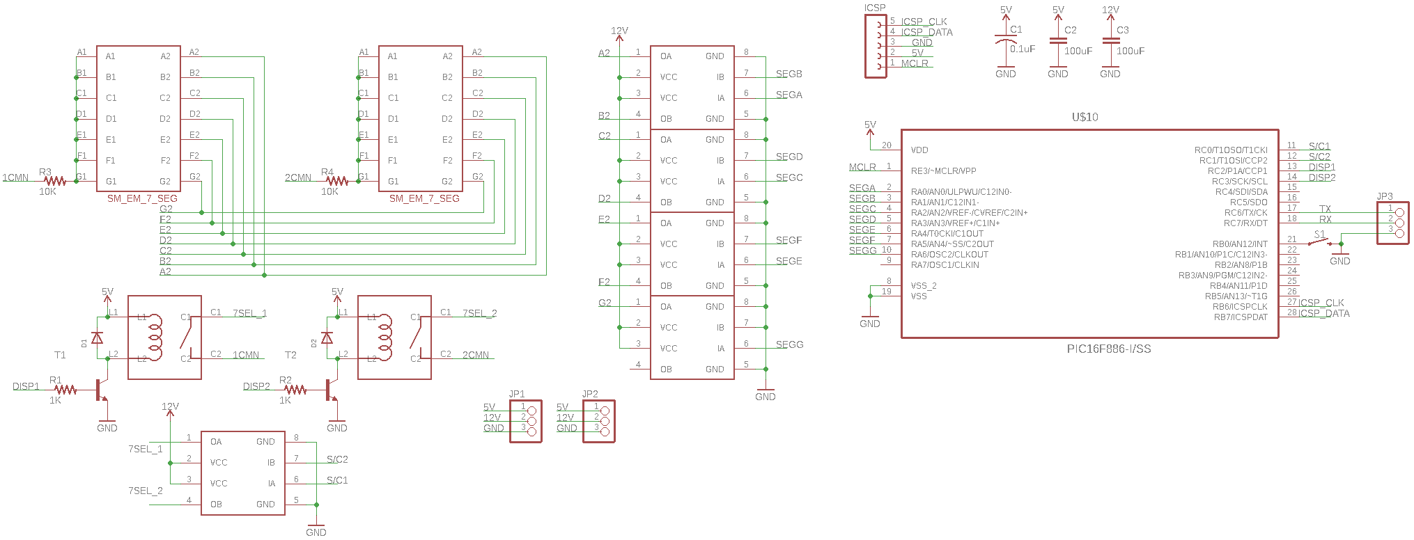 sweet sleet
hm idk
i guess i couldn't use this nodemcu
also unsure why my serial monitor is printing gibberish when i'm on 9600 baud
for reference i'm running this code https://discordapp.com/channels/327254708534116352/537365760008257569/746439552872480778
sweet sleet
i wrote this simple code. ideally this should write some number to each digit of the display.
Pastebin
Pastebin.com is the number one paste tool since 2002. Pastebin is a website where you can store text online for a set period of time.
obtuse spruce
Your serial monitor is printing gibberish because your code sends it! Serial.write((1<<4)|3); prints a 0x13 character - which is a control code... and the other lines print 0xF2 0x53 0x02 0xe9 0x45 --- you are printing whacky characters to your Serial line.
Serial is connected to the serial monitor. What control lines are connected to the digit hardware?
sweet sleet
@obtuse spruce I am trying to 'interrupt' this code that is loaded onto the PIC
i currently have a 'tx' line connecting the digits. it's possible the voltage is just too low?
is it possible for me to test this using an esp8266 nodemcu module? the 3.3v should be sufficient for the 5v logic PICs
I’m using the gnd, 12v, 5v, TX wires. Could i plug them into the esp8266 nodemcu to test with a different module?
(Where should the wires go?)
obtuse spruce
No, I don't think it is an issue of voltage at all. Your serial monitor is via the USB connection to your computer, yes?
sweet sleet
yes
obtuse spruce
But - then the tx line of this same board is then connected to the display board
and you are trying to send commands to the display board over the tx line, correct?
sweet sleet
is there a way to wire the TX wire to another esp to read the debug statements in the firmware?
yes i am trying to send over TX
I've always loved the flip digit/disc/dot type displays but they are a little frustrating to drive and most projects I've seen are hardwired for that specific implementation. I want the provide an easy to use (9600 Baud Serial with simple and well documented instruction set) m...
obtuse spruce
Okay- so I think, Serial is the serial stream over USB... so you can't use it to write to a serial connection on TX. This is why your commands to the display board come out on your debug console... that is where you are writing them.
What board are you using (not the display board, the one connected to your computer via USB)
 obtuse spruce
So we need to find out, in that core, which serial object controls TX
It is probably UART
obtuse spruce
No
sweet sleet
okay
obtuse spruce
on the D1 - the TX pin is not controled by Serial - which is what you were trying to use to write to the TX pin.
sweet sleet
hmmm
obtuse spruce
We can see this because when you write to Serial - it comes out on your debug console via USB
obtuse spruce
The messages are fine - you are sending them to the wrong object.
We need to find, in the Wemos B1 core, which UART instance is connected to the TX pin.
obtuse spruce
yes, "core" means the core headers and source files that are the implementation of Arudino Wiring for that board.
obtuse spruce
try writing those commands to Serial1, not Serial - leave your debug messages being printed to Serial
sweet sleet
obtuse spruce
No - leave the "hi" to Serial
that is test you want to see on your debugging output, yes?
whereas 0xF0 is a byte you want to write to the display boards, right?
obtuse spruce
So, do you see why you can both send "hi" and 0xF0 to the same object? That can't possibly work....
That looks better - try that.
(do you know what 0xF0 will do to the displays? Will you be able to tell?)
sweet sleet
0xF0 should just clear the displays
i'm printing one, and writing the other
do i not need to begin another "Serial"
obtuse spruce
printing and writing are the same - print is just a function that formats if needed, and calls write
so print and write end up at the same place for a given object.
obtuse spruce
so:
Serial.println("Hi, this goes to the debug console");
Serial1.print('\0xF0');
  // this goes to Serial1 - and is a funny way to output a byte
Serial1.write(0xF0);
  // this is exactly the same as the above;
I don't know if Serial1 is the the right object... I'm looking at the core files now for that board.... haven't found it yet.
What, by the way, are your options for "Debug port", besides "Serial"? (in the IDE)
sweet sleet
should the tx go into the 'rx' of the displays??
obtuse spruce
yes
well - I haven't seen schematics for the display, but almost certainly yes
unless they are expecting to receive on a different pin.
sweet sleet
there is tx, rx, and grnd
on the display modules
so it should not go into tx probably?
obtuse spruce
well - you certainly have to have GND connect - and I'd assume that the labels are from the point of view of the display - so it wants to receive (RX) - what your D1 is transmitting (TX) - so I'd expect to see it connected RX on display to TX on D1
obtuse spruce
It's blurry but it looks like you've got RX on the display boards connected to RX on the D1 board
I'm not sure what I'm seeing - what is that first, leftmost green board -
with the D1 mounted on it.
sweet sleet
obtuse spruce
gotcha- looks good
sweet sleet
i'm using this 'LOLIN' board
that should be fine too right?
Serial1 isn't writing anything to the display :/
and my serial monitor is just displaying ⸮���⸮⸮�⸮�⸮⸮��⸮⸮��
this is what my friend who made the boards suggested: Can you measure the serial idle voltage and/or capture the switching via oscilloscope during a message transfer? Assuming the messages are correct the only other thing I can think of is the 3.3v logic is "sagging" too low to be interpreted correctly for the 5v logic pics. Odd since my displays have no issue communicating at 3.3v. If you connect a single module can wire the tx pin from that module to the esp you can see if it responds with a serial debug statement (I think I set those up in the current fw).
obtuse spruce
Sorry - I was plowing through the core files for the D1 mini --- it isn't clear to me how - but it looks like Serial really is the hw TX/RX pins (and UART0) -- but somehow it is also copied to USB serial for debugging? I'm not sure how that works, and there isn't any clue in the core files. In any event, I think maybe writing to Serial is correct for the TX pin... but maybe we have to get it to not send those bytes via USB....
sweet sleet
😢 i'm stuck
obtuse spruce
If you had a scope on the TX pin you'd be able to see the bits fly by easily
sweet sleet
i don't have an oscilloscope
 cedar mountain
Picking up one of those cheap 8-channel "24 MHz" USB logic analyzers is a good investment.
obtuse spruce
The core files include this:
#define SERIAL_PORT_MONITOR        Serial
#define SERIAL_PORT_USBVIRTUAL     Serial
#define SERIAL_PORT_HARDWARE       Serial
#define SERIAL_PORT_HARDWARE_OPEN  Serial1
I'm not sure how Serial can be both the USB virtual serial cable and the hardware UART
Is that normal for some cores?!?!
cedar mountain
Best $20 I ever spent for electronics gear...
sweet sleet
hmmmm
since the tx is in series (it connects from D1 to 3 different display modules) can I connect one into a display module and then one into another esp to read?
for debugging?
since i don't have that logic analyzer
but maybe we have to get it to not send those bytes via USB....
how
Serial is correct for the TX pin since my friend was able to do the same on his displays
this good?
id buy it if it can help me to understand what in the world is happening here lol
cedar mountain
Yep, that's the kind. There are a number of random clones out there, but they should all use the same chipset and work with Pulseview.
sweet sleet
okay
got it.
i'm sad because it's really hard for me to learn this stuff
so to debug with that thing i plug tx from the driver d1 board to the rx of the display module.
then i take the other green tx/rx wire and i plug it into that logic device
and then I will be able to read the serial debug statements
obtuse spruce
Yes, looking through the core, I see now that Serial is indeed TX connected - no idea how it get over USB.... and don't know if that going over USB is "snatching" it from going HW...
okay - I've got to go to bed.... best of luck
sweet sleet
@obtuse spruce thanks for your help 🙂
@obtuse spruce are you saying i need to disconnect it from usb before starting it again?
lol
the displays flicker when i plug it in without any usb
midnight pike
Is there something I have to consider when uploading data to thingspeak? Like same notation between code and fieldname?
 plucky tundra
Hello, I've been trying to use a MPU6050 to calculate displacement via using double integration but the issue I've been running into is that whenever I move my MPU6050 even slightly and place it down, there'll always been a reading on the 3 axis even though it's supposedly to be 0 if it's still. Those values aren't consistent and kept fluctuating whenever I move and place it still. Does anyone have any solution to this issue? I've read that accelerometer doesn't drift but it is sensitive to vibration but I placed it on a table and it still occurs.
cedar mountain
Well, an accelerometer sitting on a table is going to read gravity if nothing else, so the tilt angle will probably introduce some residual reading even in the X and Y axes, and Z will be large and non-zero.
But in general consumer sensors will have some finite zero offset bias / drift that varies with temperature, time, etc. Integrating position is generally not going to be reliable over even modest time scales.
The datasheet species 50mg initial zero-offset tolerance, and 35mg over temperature. So between them that's almost 1 m/s^2 of unexpected acceleration you might expect to read.
(This is a pretty old sensor, by the way. More recent generations are much improved.)
plucky tundra
Would you recommend for me to go for a newer generation then? I am doing a project in which I need to measure movement of the human body and considering that if I can't get the displacement reliably over a period of time I think it might be a failure of a project
cedar mountain
Ideally you'd pick a different sensor method completely, such as camera-based tracking. Newer or more expensive sensors will help, but getting 3D position just from inertial measurements is hard in general, depending on what kind of accuracy requirements you have.
plucky tundra
Unfortunately the project specification requires us to use wearables so I am unable to use camera based tracking haha. Alright I'll continue to look around for solutions. Thank you!
cedar mountain
Yeah, a lot will just depend on the constraints of your problem space. Ultrasound distance tracking might be an option. There are also electromagnetic position sensors, or Inside-out optical tracking. All of these also benefit from mixing in inertial data, too.
north stream
The usual solutions to this sort of thing incorporate some form of "sensor fusion" to try to use information from some sensors to correct for errors in the data from other sensors. It's fairly complex, and many implementations are not open.
plucky tundra
Oh is this the kalman filter thing? I've heard about it and read about it briefly and it's really complex with all the maths.
Cool thanks for pointing me in that direction I'll go try it
north stream
Kalman filters are one popular approach, there are others as well, and yes, they're really complex and full of maths.
 vivid rock
@plucky tundra check the work of Kris Winer, who uses open-source Madgwick/Mahoney filters for sensor fusion:
https://github.com/kriswiner
They are much easier to work with than Kalman filter
however, calculating displacement using double integration will never work reliably because of accumulating errors. Calculating orientation in space is difficult enough; calculating displacement is much harder. I would suggest using other methods.
plucky tundra
Wow cool I'll look through it once I get an idea of how sensor fusion works. Thanks! Yeah, I am currently considering using jerk via calculating the change in acceleration but I am not sure if that's indicative enough of the movement
I'll just see how it goes. When there's a will there's a way haha
vivid rock
Kris also sells pre-programmed boards which give you absolute orientation out of the box, e.g. https://www.tindie.com/products/onehorse/ultimate-sensor-fusion-solution-lsm6dsm-lis2md
if you do not want to spedn a lot of time on figuring it out on your own.
plucky tundra
That's outside of my budget unfortunately. I still have a lot of time so I can still try and figure them out. I'll have fun trying anyways. Thanks for the recommendation though!
obtuse spruce
😫 I think I just blew up my Feather M4 --- and I don't know why! Are folks here game to help me understand what I did wrong?
So - there's the schematic - basically, 8 outputs, each connected to an opamp to bring it up to something better for synthesizer range-ish
And it was all working okay ish... then I swtiched the reference voltage circuit from cvref (on the center bottom left) to cvref2 (center bottom right)
north stream
Probably the op-amp outputs went too high for the M4 inputs and damaged them.
obtuse spruce
but - shouldn't the output be able to go much higher than the inputs can take? Isn't that the point of the op amp?
north stream
I don't understand: using an op-amp to overload inputs still overloads the inputs.
obtuse spruce
No no - I mean, I thought that the op amp served as a buffer - that despite the feedback resistor, the input and output were effectively isolated.
so input is 0 ~ 3.3V ---- and with 2.2 gain, and the offset of the ref, is 0.5V to 8V --- which it was on the breadboard
north stream
It looked to me like there was a low impedance path from the output of the op-amp to the input of the M4 but I could have missed something.
It looked to me like the power supply to the op-amp was 12V
obtuse spruce
yes it's a 0 to 12V supply - for synths.
output back to input (via feedback resistor and input resistor was a total of about 3.2K)
 tropic quail
i need some help with a node mcu amica. what is the max input amps on the board? can it withstand 4 amps?
 pine bramble
@obtuse spruce The shortest path would be to do it again, and see if it blows again. ;)
Other than that, assume it's wrong, and correct it.
I would fry things once in a while, and it really hurt (mentally, emotionally).
Mainly because there wasn't a replacement within arm's reach. Or maybe, even within any effective reach (last one, or one of a dwindling supply, never to be refilled again).
My boss used to just say, don't do that.
He trusted me to know what it was I wasn't supposed to do (in this case, blow the target board).
vivid rock
@tropic quail you provide voltage to the board. It takes as much current as it needs and no more - so you can connect 100A power supply to it and it would be OK as long as it is correct voltage.
tropic quail
ok
obtuse spruce
asked some other folks - and I think we worked out the issue - the voltages were all fine, but I didn't use large enough resistors in the feedback divider - and since this is negative feedback, it pushed too much current into the MCU
So - going to redesign with op amp in non-inverting mode... will need some calibration to avoid the clipping near 0, but I can do that in software.
north stream
I'm glad you got it figured out
 midnight mulch
Anyone know what's an appropriate core for a "standalone" Atmega16u2? Can you install the HoodLoader2 core on the 16u2 on a Due's programming port and completely break it off (save the serial connection) from the Due?
midnight mulch
When I install the HoodLoader2 board definitions, I see a few entries for the 16u2 - most of them with the Mega or Uno, but there's one that just says DFU and another that says HoodLoader2 Dev. I suppose one of these is the core for a standalone 16u2.
Aah I was able to burn the DFU bootloader to the 16u2 with the HoodLoader2 core.
midnight mulch
Now I am unable to see the board appear as a port 😕
Hmm... I wonder if the serial port of the SAM3X8E can be used to program the 16u2 lolz
Get the whole thing backwards 😄
pine bramble
There's no reason to touch the firmware in the atmega16u2 for any reason.
midnight mulch
There's no reason to touch the firmware in the atmega16u2 for any reason.
@pine bramble
Well... I'd like to do USB MIDI passthrough and the Due clone is the cheapest board around with 2 USB ports
obtuse spruce
Long shot: but does anyone who lives in Silicon Valley have a spare Feather M4 Express I could buy off you tomorrow..... I blew mine and could use another ASAP
pine bramble
It's 12:30 here I'm all like, zzzZZZ. Goodnight. ;)
midnight mulch
It's 10:00 here and I've not yet fallen asleep....
pine bramble
People do not need to be seeing all that quoted material.
Who invented quoting in Discord. It's 100 percent wrong practice.
midnight mulch
I used to work out of coffee shops and would have friends to catch up with for karaoke nights and drunk philosophy rants but since COVID-19 happened I've pretty much lost track of time due to staying home all day everyday 😂
@pine bramble fixed 😋
pine bramble
>> Anyone know what's an appropriate core for a "standalone" Atmega16u2 <<
Nope.
example of useful quoting, and how brief it can be, and still be effective.
midnight mulch
@pine bramble apparently slack changed the rules of engagement from IRC where you just @ someone you're replying to.
pine bramble
What makes it useful: cites from the scrollback, far enough back that the context isn't clear if I just said 'Nope' without it.
Quoting should always be difficult, to discourage its immediate use when the context was already quite obvious.
I don't know why it keeps coming back. Discord dev team is responsible for the architecture, at this level, and made a bad call.
Then there's the whole thing about 'top posting' I never quite agreed with. ;)
@pine bramble apparently slack changed the rules of engagement from IRC where you just
@someone you're replying to.
@midnight mulch << machine generated
________
>> apparently slack changed the rules of engagement <<
That may be so, but ...
<< properly generated by me.
midnight mulch
Yeah you can't quote manually. The syntax is awful.
pine bramble
You just agreed and disagreed with me ;) lol
Obviously each writer has a style preference.
If quoting became routine, I'd just mute that channel permanently.
(this is the first time I've even found how to quote, using the Discord user interface's offered method .. didn't know how people were doing it)
Back to studying the insides of my eyelids. Thanks for your company. Goodnight.
midnight mulch
I did. I agree that discord's syntax is off, and I also find myself getting confused as to what the correct etiquette is while jumping between apps. Each has its own cultural baggage.
 carmine canyon
was wondering if one can use ROS Actions with rosserial
 last bobcat
Hi i was working on my arduino nano and i accidentally cracked one of the as6 diodes on the underside of the board , it moved abit but i soldered it back into place
it looks like it’s a diode for the usb port , so i plugged it in and everything worked okay, is it fine?
i’m kind of paranoid because i don’t want to wait 2 weeks for another
stuck coral
I mean, if it works, you could also replace just the diode and just use it like that for now unless someone else says otherwise. The only diode I see is as you say for the USB port, if you supply 5v externally to it anyways, I would desolder it until you replace the diode, if you don't, then just leave it for now.
SS1P3L is the part number brb
last bobcat
@stuck coral im supplying voltage externally yeah, but uploading sketches via usb
it uploades with no issues
do you think i would be able to salvage something like that on some eletrics i already have?
id assume that all eletronics that take 5v usb use the same diode spec?
stuck coral
Maybe, if it were me, I would desolder the diode if you were supplying voltage externally but leaving it probably wouldnt hurt. You probably can do that, or next time you want to make an adafruit order you can make it on digikey and buy the diode.
Digikey stocks all the adafruit products
Or need anything else, they also have sparkfun parts and many parts other vendors have
last bobcat
mhm, i mean it looks like it works , ill send a picture in asec
its not totaled , it has a bit of a hairline crack horizontally
phew im glad its for usb tho
stuck coral
Yeah, I dont see how leaving it could really go bad
last bobcat
@stuck coral
i quote literally had an aneurism when i heard the snap, waiting 3 weeks for all my stuff to arrive only to break something in 10 mins lmao
stuck coral
Lol, happens
 harsh socket
hey is this the best place to get help with arduino code
im having issues with a code i wrote for a motion sensor and button
const int buttonPin = 12;     // the number of the pushbutton pin
const int ledPin =  13;      // the number of the LED pin
const int sensorPin = 14;    // Sensor pin

// variables will change:
int buttonState = 0;         // variable for reading the pushbutton status

void setup() {
  // initialize the LED pin as an output:
  pinMode(ledPin, OUTPUT);
  // initialize the pushbutton pin as an input:
  pinMode(buttonPin, INPUT);
  // Sensor pin
  pinMode(sensorPin, INPUT);
}

void loop() {
  // read the state of the pushbutton value:
  buttonState = digitalRead(buttonPin);
  sensorState = digitalRead(sensorPin);

  // check if the pushbutton is pressed. If it is, the buttonState is HIGH:
  if (buttonState == HIGH) {
    // turn LED on:
    digitalWrite(ledPin, HIGH);
  } else if (sensorState == HIGH) {
    digitalWrite(ledPin, HIGH);
  } else {
    // turn LED off:
    digitalWrite(ledPin, LOW);
  }
}```What is the issue?
tropic quail
that happens alll the time to me
 fleet pewter
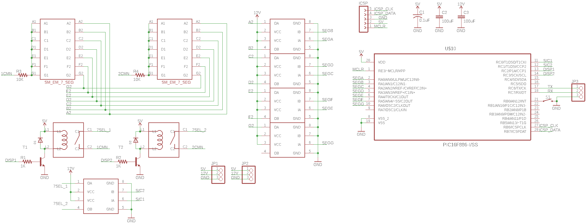
 sweet sleet
hey guys i got a logic analyzer to see what serial commands i'm getting
can someone teach me how to use it
I need to read what is being outputted by this TX line
🙏
@cedar mountain i got pulseview and the logic analyzer 
cedar mountain
Great. Pulseview should have a signal-analyzer feature where it can interpret the bit patterns of a UART for you and annotate the waveform.
cedar mountain
Yes, you'll want to connect the logic analyzer ground to your board's ground. Otherwise it won't know what "3.3V" means.
sweet sleet
So I’ll put tx wire into ch1 and gnd into gnd (ch1)
Or will i need to also put in the 5v/12v
cedar mountain
Those two should be sufficient. It gets power from the USB connection.
sweet sleet
it's hard for me to really gnd the wire. can i plug it into another gnd outlet besides the one in the board?
cedar mountain
It ought to be the same ground source that the board is using, but you could connect it to the board's battery or something like that.
last bobcat
@stuck coral , i did abit of digging and turns out it’s a usb capacitor and not a diode
but i’m not sure how that effects the situation
sweet sleet
ok
@cedar mountain i'm running it now
it's definitely sending bits. (i have it send every 10 seconds with a second delay in between)
i think the messages are correct too. maybe it is a voltage issue
cedar mountain
Cool. The yellow and green icon in the top right should be the decoder menu.
cedar mountain
That I don't know.
sweet sleet
i have this going right from the d1 to the logic analyzer. instead of D1 into display module/PIC of the display module then into the logic analyzer.
north stream
I think the displays are using their own custom protocol (which is why the serial monitor didn't show intelligible information when it was hooked to that)
More precisely, it's probably asynchronous serial, but the meanings of the bytes depend on the custom encoding.
sweet sleet
Pastebin
Pastebin.com is the number one paste tool since 2002. Pastebin is a website where you can store text online for a set period of time.
this is the firmware on the actual PIC
the Serial.write function executes the function on line 210...
is there a way for me to test what debugging texts are printed from the firmware on the PICs
If i connect a single module can i wire the tx pin from that module to the analyzer to see if it responds with a serial debug statement?
@cedar mountain is there a way to decode these commands into binary?
or decimal lol
cedar mountain
Yes, the UART decoder should do it, if they are being generated from a serial port.
It might be called serial, or RS-232, etc.
pulsar yacht
Hello, im downloading a photo from a web server with the esp8266. Im copyng the response that I receive from the get and pasting it into an text editor to save as png. The problem is that say that the format isn’t compatible. How can I know if im downloading well, and how to save this as an image?
The response start with ?PNG, so I assume that is the photo.
Thanks!
north stream
PNG is a binary format, not a text format, that's not likely to work.
pulsar yacht
and if its jpg its possible?
north stream
Pretty much all image formats are binary formats, aside from some special purpose ones like the ASCII encoded netpbm/pbmplus files.
pulsar yacht
but its possible to download an image with an http get?
north stream
Yes, that's a very common operation.
Sometimes when people need to transport binary data over a text channel, they'll use Base64 encoding.
pulsar yacht
sorry, i need to make the get, and convert to base64?
north stream
That depends on what the server supports. It's easier if your reception process doesn't include copy/paste into a text editor.
sweet sleet
hmmm i'm not sure what i'm doing exactly
Pastebin
Pastebin.com is the number one paste tool since 2002. Pastebin is a website where you can store text online for a set period of time.
this is the code i'm running
this is the first serial command sent
this is the correct command.
for some reason the PIC is not performing the command correctly :/
i am trying to now test this with the esp8266 wifi instead of the d1. what pin should i use for Serial.write? gpio1 or gpio2?
Nodemcu
 frank cipher
hello there
i have a question about SPI.transfer()
if i'm receiving a byte
with data = SPI.transfer(0)
could that dummy value be any value (or) does it have to be a 0? and does it actually send 0x00 ?
pine bramble
my arduino stops working if I keep it on for a long time and I have to press to the restart button for it to work again, is there a solution to keep it on all the time
lone ferry
@pine bramble What do you mean, "stops working"? Does it turn off / become very hot, or does your program simply not do what you want anymore? In the latter case, it's probably a programming error such as a counter that is overflowing.
 past sail
Hello everybody. I am kinda new to this and just soldered up my first 16x16 LED grid, out of a single strip of addressable LEDs. I would like to display Japanese kanji characters on it in a 16x16 format. I found a multilingual fork of the adafruit core gfx library by someone named joeycastillo on github and would like to use it with the adafruit neopixel library. Does anyone know how I would go about doing that? How do I let the adafruit library know to use the multilingual fork instead.
Or, if anyone knows of an easy way to display unicode characters on an led matrix i would love it if you could point me in the right direction
tropic quail
anyone have any experience connecting esp8266 board to ifttt
 round pecan
hey everyone. I need some help with replicating some of the Bluefruit Connect Apps output.
I got a feather 32u4 ble, which I want to control with a custom app. I'm using the code from this https://learn.adafruit.com/ble-feather-lamp/software and got the app mostly set up in MIT App Inventor. The animations work fine so far, the trouble now is that I also want to implement a color wheel (like the bluefruit app), but I can't seem to get the numbers (like 255,255,255) to read correctly.
And yes, i'm extremely new to all of this and didn't know anything about all of this two weeks ago.

 fallen dome
can you take a user input with arduino..like the user can input some sort of value and get a output like in bluej
pine bramble
can I fit an arduino-type small microcontroller into a sega genesis cartridge, to control LED's?
obtuse spruce
@past sail - I'd think thatn AdafruitGFX is the wrong tool for this job. I don't think it supports display onto a matrix of neo pixels, and I think it is doing well more than you need.
The heart of your problem is:
- Find a suitable source of kanji bitmaps, and get that into a 16x16bit (so 32 bytes each) format. And store that in the flash or sdcard on your board.
- Manage the mapping between the kanji you want to display and where in that data it is.
- Put the bits out onto the neopixel matrix.
Step 3 is the easiest of these, and hardly needs a library - I'll be happy to help you develop that code if you need.
You don't say how many kanji you need available, nor how the system will choose which kanji to display when. These details will inform the three steps above.
midnight mulch
Anyone know what's an appropriate core for a "standalone" Atmega16u2? Can you install the HoodLoader2 core on the 16u2 on a Due's programming port and completely break it off (save the serial connection) from the Due?
@midnight mulch
Thought I'd share an update.
I was able to use HoodLoader2's 16u2 core to directly program the 16u2 but without a bootloader (I had to use my Uno as an ISP).
I managed to get 4 LEDs blinking a pattern via the 16u2 and then used the native USB port to make the built-in LED of the Due blink a different pattern 😁
round pecan
does anyone know how I can find out what Bluefruit Connects output values for the Color Picker are?
north stream
@frank cipher SPI is an interesting protocol. One bit is transferred in each direction with every clock, so to send, you have to receive, and to receive, you have to send. This is why the dummy values are there. Which dummy value to use depends somewhat on what you're talking to, but most devices will simply ignore the receive bits while they're sending (even though the protocol supports sending and receiving simultaneously, many devices just do one at a time).
 royal lava
can someone help me modify my code? I have an arduino mega with a lcd shield running a stepper motor. I have two menu items right now one to run and one to reset the motor. I would like to change the menuItem2 to run the motor in the opposite direction but cant figure it out.
Pastebin
Pastebin.com is the number one paste tool since 2002. Pastebin is a website where you can store text online for a set period of time.
obtuse spruce
I think before your while loops, you need to set the speed: positive for clockwise, negative for counter-clockwise.
You have some key matrix wired with resistors? I'm guessing as it looks like you are doing one analogRead to determine which button is pressed?
royal lava
to be honest im not exactly sure, I found this template for my lcd shield and tweaked it for my needs
so before the while loop i can set the speed?
obtuse spruce
what is the model of the LCD shield?
past sail
@obtuse spruce Thank you for the info. I will try it on my own first and return if I need help. The kanji I am trying to display are the Japanese language proficiency test kanji. I have two posters in my room that have all the kanji on them and thought an led matrix that displays them would look nice along side the posters. They are color coded by level from level N5 down to N1. So, I was going to have the displaye show them by level and in the correct colors.
obtuse spruce
yes, just before the while loop - in both functions - set the speed. Positive in one and negative for the other. BUT - you should really consider not having so much repeated code. These can just one function with a bool argument that says forward or backward.
ah yes - it is a resistor network keypad! But I really don't understand the if (readKey < 790) { logic. If that is some attempt at debouncing, it isn't right.
But, this is an aside from your main issue.
royal lava
yeah, im pretty new to coding in general and specifically arduino
obtuse spruce
@past sail - that sounds perfect and should be pretty easy to do. The hardest part is going to be finding the Kangi bitmaps and figuring out the way they are stpored.
north stream
It sounds like Kyo has found the bitmaps in a forked repository, it's probably possible to extract and re-use those, even separate from the library itself (that is what I would do).
obtuse spruce
same here, @north stream
past sail
Extract and reuse. Got it. Ill see if I can figure out how to do that.
obtuse spruce
@royal lava - any luck?
royal lava
i modified the code but am in a meeting right now so ill test as soon as im out
this is how i modified the code while im waiting for this meeting to get over ```void menuItem2() { // Function executes when you select the 2nd item from main menu
int activeButton = 0;
lcd.clear();
lcd.setCursor(3, 0);
lcd.print("resetting");
long stepSpeed = -1000;
stepper.setSpeed(stepSpeed);
while (activeButton == 0) {
stepper.runSpeed();
int button;
readKey = analogRead(0);
if (readKey < 790) {
delay(100);
readKey = analogRead(0);
}
button = evaluateButton(readKey);
switch (button) {
case 4: // This case will execute if the "back" button is pressed
button = 0;
activeButton = 1;
break;
}
}
}```
is this what you were suggesting
obtuse spruce
roughly
it looks like you have a stepSpeed global value already....
One thing - your code has a lot of duplication, and too much crammed in each function - as such it makes the code harded to read, reason about, and modify. Here's a refactoring I did of your code (hope you don't mind)
int readKey();  // declare it here, defined below.

void runMotor(bool backward, const char* message) {
  lcd.clear();
  lcd.setCursor(3, 0);
  lcd.print(message);

  stepper.setSpeed(backward ? -stepSpeed : stepSpeed);
  while (true) {
    stepper.runSpeed();
    if (readKey() == 4)
      return;
  }
}

void menuItem1() {
  runMotor(false, "running");
}

void menuItem2() {
  runMotor(true, "resetting");
}


const int noButtonPressed = 6;
  // I don't know what evaluateButton returns if there is no button
  // pressed, so change this as to what that function does.

int readKey() {
  int lastReading = noButtonPressed;

  while (true) {
    int nextReading = evaluateButton(analogRead(0));

    if (nextReading == noButtonPressed)  return noButtonPressed;
      // if the button is up, nothing is pressed

    if (nextReading == lastReading)      return lastReading;
      // if the button is same as the last time, then same result 100ms
      // apart, so it is now stable, and return it.

    lastReading = nextReading;
    delay(100);
      // button value has changed (or first time), wait 100ms and read again
  }
}
You can see that the vast complication in your code is reading the keypad - so pull that out into a separate function. And the two menu items are basically the same - so make them call a common function.
Now the code to run the motor is very clear. And the code to read the keypad (which I fixed to actually debounce) is separate, and can be evaluated on it's own, rather than it being mixed up in the motor loops in both menu funcitons.
royal lava
what is debouncing?
obtuse spruce
When you press a key down - as the contacts make contact, they flicker on and off over a millisecond or more... You generally want to wait until the value read is stable for a bit - otherwise you read down/up/down/up/down/up/down... as the user is pressing.
It looks like the delay and double read in your code was lifted from some other code that was doing debouncing (the general reason to read a key twice) - but seems to have lost the actual debounce logic (since it just uses the second read, no matter what!)
royal lava
alright, i will try to implement your code in it. seems much cleaner.
i have saved it in notepad++ so i can play with it later
obtuse spruce
When you do, if you don't understand any bit of it - please ask and I'll help explain.
royal lava
I really appreciate your help
so before trying to change the code, i just tried to use what I had to see if the motor would reverse and it doesnt. the speed increases but it doesnt change direction
royal lava
@obtuse spruce https://pastebin.com/6HGLhADF here is my complete code if you could help me out, i would be forever grateful. I got lost on where to add your code to change it.
Pastebin
Pastebin.com is the number one paste tool since 2002. Pastebin is a website where you can store text online for a set period of time.
obtuse spruce
The code I offered only replaced the two menu functions at the end. But the menu code could easily be refactorrd to use the better keys reading routine.
Note my first comment, and changed the value to zero.
royal lava
i get this error when I try to replace the code though 'int readKey()' redeclared as different kind of symbol
obtuse spruce
oh- just rename my function then to like readActiveKey
(the function, and the call to it)
royal lava
oh gotchya
k that passed the verify now. let me try it.
now the motor doesnt spin in either direction
I can feel it clicking though
obtuse spruce
what value do you have for stepSpeed - does that value make sense?
royal lava
316.0299659 i need this speed based on my gears to rotate at roughly the same rate as the earth. I am making a star tracker if I havent said so already.
this is microsteps per second
obtuse spruce
you are calling disableOutputs in setup
royal lava
ive tried with and without this. I read that this helps the motor not heat up when not in use
obtuse spruce
well - if you have it disabled while you call runSpeed won't that stop the motor from working?
nevrer mind
that just shuts off all the pins once - call ing runSpeed will reset them as needed
You should put some Serial.println() statements into your code to see where it is going
first of all - are you seeing "running" or "resetting" on the display?
also, did you fix this line of code:
const int noButtonPressed = 0;
i did but I fat fingered it. that fixed the not running issue. but the resetting still goes the same direction as the running