#help-with-arduino
1 messages · Page 69 of 1
 pine bramble
Still failed
Maybe the wiring
Weird
It's wired properly
@obtuse spruce
No luck
I'm going to study
 nova comet
Hey there
Ive been trying to use this bluetooth chip (HM-10) and im having some real issues. My code is as follows:
#include <SoftwareSerial.h>

SoftwareSerial mySerial(10, 11); // RX, TX

void setup() {

Serial.begin(38400);

Serial.println("Enter AT commands:");

mySerial.begin(9600);

}

void loop()

{

if (mySerial.available()) {
  Serial.write(mySerial.read());}

if (Serial.available()){
  mySerial.write(Serial.read());

}
when i send AT in the serial monitor i get no response from the bletooth chip
however, when I connect and disconnect from it it does send CONN-LOST etc to the serial monitor
my circuit looks like this
Anyone have ideas as to why im not receiving responses to AT commands?
 odd fjord
are the wires soldered to the protoboard or just stuck in the holes?
odd fjord
just checking...hard to see in the picture.
odd fjord
Just to understand the circuit -- looks like you have a voltage divider on Pin 10 to go to the device -- is that correct?
2 1K resistors? so the 5V signal will be a 2.5V. Am I seeing taht correctly?
odd fjord
Maybe I can't see the colors. they look the same to me.
nova comet
Im colorblind but i do recall a 1k and 2k im pretty sure
odd fjord
yes -- left one could be a red stripe--- ok
nova comet
If the voltage divider was done incorrectly would that affect the information being sent TO the module or FROM the module?
odd fjord
I'm assuming that is the output from the Uno but I don't know. What is it supposed to be?
actually it looks like taht is RX -- so I'm confused -- are you sure you have RX/TX correct?
nova comet
Im fairly certain since i no longer receive any data when i switch them
odd fjord
OK -- I'd better let someone else with more knowledge of such things help.
nova comet
Thanks anyways
 lone nimbus
good day everyone
 north stream
What's up?
north stream
Hmm, one end is one of the 2 white wires, tap is a bare? wire to pin 1?, other end is one of 2 red wires, and a brown? wire to pin3?
nova comet
im sorry i just got hella confused lmfao
the leftmost white wire goes to pin 10
the rightmost white wire goes to 11
 stuck coral
Why is a voltage divider being used in the first place? It works on 3.3 or 5V unless you have a off brand generic one that I dont know about
stuck coral
I think you should read documentation for your module, and not what other people have. Similar or the same?
So if you feed it 5V, it uses 5V logic in every HC-10 Ive seen
Working off memories from years ago so maybe Im totally wrong but could you send me a link to your module?
 stuck coral
Im not reading HM-10, Im reading HM-18/19
nova comet
i have an hm18
stuck coral
But then you need the voltage divider so carry on, i see it only allows for 3.3V
Ive been trying to use this bluetooth chip (HM-10)
nova comet
yeah i usually say hm10 because the documentation on the hm18 is scarce and the 18 is just a remake of the 10
according to dsd
stuck coral
It is a remake, one that has a different operating voltage
stuck coral
It appears to be right but I have to agree with @odd fjord the resistors look like the same value though that shouldnt really be an issue
nova comet
hm
i checked with a bunch of ppl and from this picture they said the looked the same
but then
from this one
they looked different
 cunning reef
My arduino kit came with something called a "mega prototype shield v3". What is it?
cunning reef
Hold on, lemme take a picture
stuck coral
I think the camera is playing tricks on you in that last photo @nova comet but you could be right
cunning reef
nova comet
yeah
lone nimbus
anyone have a ballpark idea of long it should take an esp8266 to connect to wifi?
nova comet
@cunning reef its a prototyping shield
odd fjord
I can be put on top of the Arduino Mega (is there a Mega in your kit) to allow you to add your own circuits
stuck coral
@lone nimbus not long, if you're having to ask the question than there is probably an issue of some sort
cunning reef
Thank you!
lone nimbus
it was connecting quickly and now this morning it is taking forever
cunning reef
@odd fjord yes, I have mega super starter kit
odd fjord
sounds great -- Enjoy it!
stuck coral
@lone nimbus does it connect eventually?
lone nimbus
it did last night, quickly
now this morning, just attempting
I'm using the same network for everything in my house
so the network itself is operating
stuck coral
Does your router reset itself every night?
lone nimbus
no
nova comet
@stuck coral so, if the voltage divider is correct? Then what could be the source of my problem? If you scroll up a bit you could see my code etc
stuck coral
@nova comet Im not sure, I would bring the pin HIGH, and just measure the voltage on the TX pin so ensure the circuit is correct
@lone nimbus not sure, only thing I can think of is a router reset causing it to select a new channel
nova comet
Bring which pin high? Also i dont have a multimeter to measure the voltage, mine broke @stuck coral
stuck coral
@lone nimbus switch your module to be verbose
lone nimbus
ill do some googling
stuck coral
Tools > Core Debug Level > Verbose
Then in the serial monitor you'll get a bunch of debug information
lone nimbus
it finally connected
i am trying to post my temp/humidity data from an dht11 to a mysql database on my pi3
but every attempt fails according to myphpadmin
no data enters the database
HTTP Response code: 200
this is what prints in the serial monitor
and i did not see a verbose option in that menu tree @stuck coral
stuck coral
Was there a debug option? The 8266 might be a tad different from the 32. And you'll have to look at your application because if it returns a 200 that means there was no client, encoding, or server issue and it succeeded
stuck coral
WiFi would prbably be the one you want, that is quite different from the ESP32. And yeah
lone nimbus
it is only returning the same data in the serial monitor
more or less
do i need additional code to make it print additional debug information?
this screenshots show that mysql is recieving failed requests
is there a log in myphpadmin?
stuck coral
Nope, should just print, Idk why it wouldnt be, I done use the esp8266 much. And it looks like the error in the picture is a php failure not the fault of the ESP8266.
lone nimbus
thats what i was thinking
stuck coral
is there a log in myphpadmin?
No idea, maybe theres a php developer here
lone nimbus
i need to edit my config file
nova comet
Im fairly certain my issue is with sending data to the bluetooth module from the arduino, so i guess the RX pin on the module. However, Im not sure why, as the circuit appears correct and so does my code.
is there anyone willing to help me with the issue for a few minutes so i can finally resolve it
stuck coral
Did you follow my suggestion just to ensure the circuit is correct so you can move onto if its a software issue?
nova comet
i asked you a question in response to that suggestion but i got no response
Bring which pin high? Also i dont have a multimeter to measure the voltage, mine broke @stuck coral
@nova comet
stuck coral
Oh, lol, multimeter is an important part of my suggestion.
And the TX pin you're using for the divider
nova comet
im lead to believe that the issue lies in sending data from the Arduino to the module, as I do receive data when connecting as disconnecting from the chip, just not when sending AT commands from the arduino
i think that would be the RX pin on the module?
not sure how to remedy that
@stuck coral
stuck coral
The issue is between your software serial TX pin and the module's RX pin. SoftwareSerial is pretty well figured out so I would be surprised if that was the issue. But try allowing a sort of echo of what you're sending the device just to make sure the sketch is working right, then you know its either the connections you made, or the software serial library setup
#include <SoftwareSerial.h>

SoftwareSerial mySerial(10, 11); // RX, TX

void setup() {

Serial.begin(38400);

Serial.println("Enter AT commands:");

mySerial.begin(9600);

}

void loop()

{

if (mySerial.available()) {
  Serial.write(mySerial.read());}

if (Serial.available()){
  int v = Serial.read();
  mySerial.write(v);
  Serial.write(v);
}
i just found some new sample code online that i tried
let me
share that
#include <SoftwareSerial.h>
SoftwareSerial BTserial(10, 11); // RX, TX
// https://www.pjrc.com/teensy/td_libs_AltSoftSerial.html


char c=' ';
boolean NL = true;

void setup()
{
    Serial.begin(9600);
    Serial.print("Sketch:   ");   Serial.println(__FILE__);
    Serial.print("Uploaded: ");   Serial.println(__DATE__);
    Serial.println(" ");

    BTserial.begin(9600);
    Serial.println("BTserial started at 9600");
}

void loop()
{
    // Read from the Bluetooth module and send to the Arduino Serial Monitor
    if (BTserial.available())
    {
        c = BTserial.read();
        Serial.write(c);
    }


    // Read from the Serial Monitor and send to the Bluetooth module
    if (Serial.available())
    {
        c = Serial.read();

        // do not send line end characters to the HM-10
        if (c!=10 & c!=13 )
        {
             BTserial.print(c);
        }

        // Echo the user input to the main window.
        // If there is a new line print the ">" character.
        if (NL) { Serial.print("\r\n>");  NL = false; }
        Serial.write(c);
        if (c==10) { NL = true; }
    }
}
this one does provide an "echo" of serial.read
and i do see my commands are sent
but i receive no response
stuck coral
Not sure, if you have known working code, and a known working library, In inclined to think its your circuit
I gotta go do some chores, brb
nova comet
@stuck coral @ me when you are back
stuck coral
@nova comet back for <30 min
nova comet
So what do u suggest i do with the circuit if we think that is the issue
stuck coral
Well sadly since you dont have a multimeter its hard to verify that it is a hardware vs software issue, I would like to be able to say for certain that it is the voltage divider.
stuck coral
What is posting to the db? I get you have an ESP8266 but what application are you using to serve that HTTP request?
stuck coral
That doesnt really answer my question
What bit of software is taking the HTTP request, decoing it, and sending it to the db?
nova comet
Doesn’t the voltage divider only affect the TX of the module
stuck coral
The RX
Since you want to take teh 5V from the TX pin of the arduino, and convert to 3.3V, and give it to the RX pin of the BT module
lone nimbus
im using a php script. im modifying this project to use a dht11 because i have one on hand. trying to learn the ins and outs so i figured this would be a good place to start. ill post a link
stuck coral
I would look at the PHP script, I never use PHP so I wouldnt be able to tell you but that seems to be your issue
lone nimbus
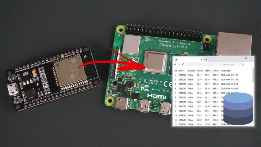
Build an ESP32 or ESP8266 client that makes an HTTP POST request to a Raspberry Pi LAMP server (Linux, Apache, MySQL, PHP). The RPi has a PHP script to insert and visualize your data.
do you recommend another solution?
stuck coral
There are many other solutions you can use, but if you are already familiar with PHP I would check your code
nova comet
Pretty sure its the voltage divider @stuck coral
The only thing not working is transmission of data from arduino to bt module
stuck coral
Me too, cannot verify without a multimeter if there is no visual issue
 narrow jackal
Hello!
I'm working on a project that involves using voice commands from an Alexa to move a stepper motor
I'm using an Arduino UNO with a CNC shield on top to move up to 4 stepper motors
I'm using an ESP8266 to communicate with Alexa
Right now I'm stumped as to how I would use Alexa voice command input to get feedback from the Arduino. Would I need a relay of some sort? Could Alexa input be used as a boolean or a value that I could then use to move the motor? Basically, I want to know whether or not an Alexa voice command could be used as an input as a boolean or string value in my Arduino code
stuck coral
You need to write an alexa skill
narrow jackal
You need to write an alexa skill
@stuck coral thanks for the fast response! So would the Alexa skill be able to communicate with the Arduino code, feeding it values?
stuck coral
It will communicate with your skill, you need to then write a service or lambda function that can take that data and communicate with the ESP8266
narrow jackal
Sorry, I'm not entirely sure what you mean.
The skill is for invoking request based on voice commands, and from there I need to write a lambda fuction that uses the data to communicate with the ESP8266?
stuck coral
Yes, because your ESP8266 isnt exposed to the internet, and you really dont want it to be
narrow jackal
I was using the ESP8266 to get picked up by Alexa, and I used my WiFi for it. Is that what you mean by exposed by internet? If so, should I use an alternative rather than an ESP8266?
stuck coral
Looking at the skills page, I think you might be able to skip the lambda since its on the same network but Im unsure of how the HTTP module behaves
But in that case, I would have the skill make a HTTP request to your ESP8266 when you say your command if thats easy
narrow jackal
Ohh, and that way the Alexa and ESP8266 communicate through the HTTP server
stuck coral
Well I think you could make the ESP8266 a HTTP server
narrow jackal
Yeah the example code I'm using seems to have done that
Alright then, I guess I would need to build an Alexa skill that would send HTTP requests based on voice commands then
Last question, I'm not sure if there's an answer for it
I have an Arduino UNO on top of a CNC shield. The CNC shield does not use TX,RX,3.3V,ground, or reset pins. Is there some possible way that I can free up those pins even though the CNC shield is on top of the Arduino?
stuck coral
To connect them to? You can solder wires to the solder joint on the shield, normally we would use stacking headers if you didnt have headers soldered to it already
Or if you have a second sheild you want to connect, you can put stackign headers on that
narrow jackal
Will that work even though the shield has headers inside those pins? Or would I bend those? I'm not familiar with stacking headers
stuck coral

“How could something so simple be so useful?”
We heard once that in the 4th millenium B.C. some guy asked the person who invented the wheel that ...
Does looking at it make sense?
narrow jackal
I'm not entirely sure
The shield I own would have to be stackable then?
I own a Protoneer CNC Shield Ver. 3.00
narrow jackal
To connect them to? You can solder wires to the solder joint on the shield, normally we would use stacking headers if you didnt have headers soldered to it already
@stuck coral is there an alternative to soldering or would I have to in order to get the connection?
stuck coral
So what are you trying to connect to those pins again?
narrow jackal
I want to use these pins to connect my Arduino UNO with my ESP8266
The labeled pins are the ones being used by the CNC shield
stuck coral
Do you have like a ESP8266 shield?
stuck coral
Nope, then your best bet is solder
narrow jackal
Hmm
 woven fox
Hey peeps, is the wiring on the pulldown for this button wrong? Will it float?
woven fox
Ok ty. Trying to figure out a problem and just wanted to get someone else’s opinion.
stuck coral
If the wire to the right is to the input, and the orange one to the left is VCC, than it is correct
Do you need debounce on the button?
woven fox
The problem I’m having is between two Nrf24L01 modules. I’m still super new to Arduino.
 amber gulch
@north stream you know how last night you told me i can put my pins in the analog holes
https://media.discordapp.net/attachments/538149593246859313/741192832689373204/unknown.png what would i write for the code

 cedar mountain
The Arduino does have predefined constants for the analog pin names, so you can do #define MY_PIN A2 to match how they're labeled on the board.
amber gulch
oh ok thanks
is this right @cedar mountain ?
i have 4 stepper motors attached to a proto shield
cedar mountain
Yep, that looks good.
Internally the Arduino headers have a #define A0 21 or whatever the underlying pin number really is, so everything gets translated to an integer eventually.
cedar mountain
It uses projected infrared structured light patterns to measure the distance to and shape of objects in its camera view.
amber gulch
yeah
the thing im makin g
basically it is like a robot that copies the person who is doing the movement in front of it
do u know any coding to sync them together?
cedar mountain
There's a lot of software out there to get body position from Kinect data. "Skeleton tracking" is a good keyword to search, for instance.
amber gulch
i found this website that does something really similar to mine
but it uses servo motors instead of stepper motors
and idk how to change it up https://www.instructables.com/id/Kinect-controls-Arduino-wired-Servos-using-Visual-/
cedar mountain
Probably your stepper library will have a "move to position" function which you can use like a servo command.
amber gulch
you want me to be honest?
i have no idea how to code this lol
idk how to make a move to position function
cedar mountain
You might not need to make it yourself. The stepper library may already have it.
amber gulch
oh really?
how can i find that?
have u working with the kinect before?
this is due tmr and i have no idea how to finish this lol
cedar mountain
No, just generally familiar with it as a neat device.
... Yeah, tomorrow is not likely to happen, I'm sorry to say. It's a fairly complex project even for an experienced Arduino developer.
cedar mountain
Well, a problem like "how should I define my stepper pin constants" is like the first 0.1% of what you have to build to end up with a robot that copies human movements. So, take how long you wrestled with that, and multiply by like 1000. That's how much more you have to figure out. 😅
amber gulch
LOL
i need someone to help me
i got some code from somewher
but it uses servo motors
and it looks pre simple
how do you move the stepper motor?
cedar mountain
Open-source electronic prototyping platform enabling users to create interactive electronic objects.
amber gulch
ty
 civic saffron
might thuis help you connect ?
@woven fox
this appears to be the same situation as what you asked for.
 scarlet hemlock
Hi there, I am looking for a source for a Arduino Mega without (!) headers. Any suggestions?
amber gulch
seriel port not selected?
north stream
The Arduino IDE needs to know what serial port your board is connected to, to download the code into it. You can go to the Tools -> Port menu to select it
 slate pendant
how do you correctly construct a http POST? I cant get it to work but I currently have this:
  WiFiClient client;
  HTTPClient http;
  http.addHeader("Content-Type", "application/json");
  int httpCode = http.POST("Congratulations! You've fired the Door_Opener event");
  if (httpCode == HTTP_CODE_OK) {
    Serial.print("Update received: ");
    Serial.println(http.getString());
    digitalWrite(RelayPin, HIGH);
    delay(TimeOpen * 1000);
    digitalWrite(RelayPin, LOW);
  } else {
    Serial.printf("[HTTP] Update failed. Code: %d\n", httpCode);
  }
 vivid rock
@scarlet hemlock you can look for clones on amazon or aliexpress, e.g. https://www.amazon.com/ATmega2560-16AU-Development-Without-Unsolder-Header/dp/B07GBV6GN9
 gilded swift
Alternatively, if you want to be super creative, you can design your own 😬
vivid rock
do you need exactly MEGA or would another board with sufficiently many pins also work? in that case, I would also suggest adafruit grand central: https://www.adafruit.com/product/4084

Are you ready? Really ready? Cause here comes the Adafruit Grand Central featuring the Microchip ATSAMD51. This dev board is so big, it's not named after a Metro train, it's a whole ...
which is MUCH more powerful (120 Mhz vs 16 Mhz for MEGA)
 neat bone
plz nobody to help me with the anemometer tx23 ?
 jagged void
https://learn.adafruit.com/32x16-32x32-rgb-led-matrix/connecting-using-rgb-matrix-shield // hello everyone, i just bought the 16x32 matrix as well as the shield for it above. problem im having is when i try uploading code it goes on and off and the Arudino IDE says "error COMP3 not found. so i take off the usb cable for it and when i plug it back in, the original demo saying "16x32 RGB" pops up. im wondering if im not giving it the amps i need. any help will be appreciated

Adafruit Learning System
Hundreds of pixels of eye-blasting LED glory!
north stream
@neat bone What problem are you having with the anemometer?
@jagged void Yes, could be a power problem
scarlet hemlock
@vivid rock @gilded swift thanks, I bought some from Aliexpress. I designed a PCB where the Mega plugs into female headers. That means, I need male header pointing down
neat bone
hello, i can't read the data for the wind speed
north stream
There's some information for doing so here https://forum.arduino.cc/index.php?topic=205501.0
neat bone
i have the same problem thx
jagged void
Hmm I wonder where this code from. I just wanna be able to rewrite what says in the board. This only pops up as well only when I plug the arduino into my computer. Even if I upload code then unplug it it comes back. Vise Versa for dc power. Any help to get code to just write on the board like this would be just more than fine!
north stream
You should be able to edit the example code to change the text
slate pendant
in arduino go to file - example, then navigate to your board and look for a fitting example
 rugged wigeon
Hi there i'm looking for some advice about using a Ethernet FeatherWing with a Feather M0 with built in lora radio. So my question is can the lora radio still be used as the documentation for the Ethernet wing says the lora needs to be disabled for the Ethernet wing to work
slate pendant
if the documentation says it doesnt work it doesnt
the radio probably uses the same antenna as the wifi
jagged void
The error only pops up every now and then when I upload, I’m trying to get the error code so I can show (:
@safe shell
rugged wigeon
@slate pendant erm its ethernet no wifi
 safe shell
the radio may generate too much noise for the Ethernet FeatherWing, or some pin conflict maybe
@jagged void I can't read the text on the video, better to copy-and-paste the text, or take a digital screenshot of the error messages
jagged void
It said the error comp3 not found
Arduino: 1.8.13 (Windows 10), Board: "Arduino Uno"
Sketch uses 11298 bytes (35%) of program storage space. Maximum is 32256 bytes.
Global variables use 417 bytes (20%) of dynamic memory, leaving 1631 bytes for local variables. Maximum is 2048 bytes.
Error opening serial port 'COM3'. (Port not found)
This report would have more information with
"Show verbose output during compilation"
option enabled in File -> Preferences.
@safe shell
safe shell
"COM3" ...it can't find your serial port
if that's intermittent, make sure you are using a quality cable that you know always works, and that all connections are tight
jagged void
ive tried changin the COM too. ive done all and nothing. even plugged the shield to metro m0
safe shell
sometimes it works, or never?
jagged void
it only stays on how i showed in the video and i can only get that code to display. maybe not enough current??
this example has never worked sadly
or any in fact
just the one in the video i showed
safe shell
highest probability issues that come to my mind are: (1) the port is wrong; (2) the cable is bad
that's assuming you always get a port error in the IDE (which means your code is never uploaded to the device)
jagged void
Ahhhh I seeee so no uploading if cable is bad
safe shell
right, or if the wrong port is selected in the Arduino IDE
jagged void
I see, I’ll figure it out hopefully thanks for all your help today! May the universe bless you. Have a good one!
safe shell
Most likely wrong port, that's what the IDE is telling you
rugged wigeon
i've just checked and I can't see any pin conflicts. both use different cs pins
jagged void
FIGURED IT
Under volt and not enough amps, plugged in into computer and dc and worked fine!
narrow jackal
If I used this circuit to connect a DRV8825 to an Arduino, could it also be possible to integrate an ESP8266 ESP12E with it as well?
Like something like this?
I'm not entirely familiar with building circuits, but I'm wondering if the connections could be somewhat isolated
Both use GND pins so I'm wondering how I'd be able to get that to work
nova comet
Hey, Im totally lost. I've been working with this Bluetooth module for several days now and I am still unable to make it receive data from the arduino serial. I am able to send data from the module to the arduino but not the other way round. I just redid my voltage divider circuit thinking that may be the issue, but it still will not work. Heres my circuit
Those two resistors are 1k and 2k, they may currently be in the wrong positions but I've tried both ways just because why not. Im colorblind so idk which is which.
My code seems fine too
Pastebin
Pastebin.com is the number one paste tool since 2002. Pastebin is a website where you can store text online for a set period of time.
rugged wigeon
@nova comet you might want to ask in the help-with-radio channel instead as that is for help with things like bluetooth specifically
nova comet
Oki
narrow jackal
Can I bump my question
odd fjord
@narrow jackal It looks like you had some responses yesterday, if you need more help and it's been a day, it's OK to post a followup question.
narrow jackal
Actually I figured out that the CNC shield has RX and TX pins just above the end stops, so I just might be able to figure something out
odd fjord
looks like you have what you need there.
 fickle cosmos
Hey everybody, hope you are having a great day. Would it be possible to use Arduino to, say, control a monitors brightness via serial? I am thinking about taking a set of push buttons and I want them to turn my monitors brightness down completely or up completely. The computer in question is running Ubuntu.
A point in the right direction would be much appreciated. I'm no expert and I've spent some time trying to figure it out
 errant geode
Is it possible to use one pin with both input and output? Or connect 2 devices to input or output? I have esp8266 and i dont want to switch to esp32 or add pin expanders, becouse i want this project to be small and simple. I want to connect raindrops module, termometer module, touch button, neopixels and ir reciever, but i have only 4 pins left (including analog one, that is required for raindrops sensor). Is it possible to use one pin for 2 devices? If yes, which devices are best to use both on same pin?
vivid rock
@fickle cosmos not sure about serial, but arduino can be programmed to act as additional USB keyboard (or more general USB input device), and then you can configure the computer to use that additional "keyboard" to control monitor brightness. Quick google serach gives, e.g. https://www.instructables.com/id/Arduino-Programmable-Button-Panel-As-Keyboard/

Instructables
Arduino Programmable Button Panel As Keyboard: This is a pretty simple and fun project with Arduino which is an ideal option for your first interaction with Arduino. You will create a panel with different buttons, each one will do an action in your computer (Mac or Pc) by emul...
narrow jackal
If I ground my reset pin to gnd can my Arduino be used for anything else, like moving stepper motors for example?
stuck coral
Do not ground your reset pin, then it will stay in a reset state
narrow jackal
In the resources I've read talking about how to connect an Arduino to an ESP8266 (I'm using ESP-12E) they all say to do it to make it a USB Serial connector or something
I hope there are other approaches, I really need the Arduino to be able to do things
stuck coral
What does that have to do with the ground pin? And I think usually I see SPI connecting a co processor with the Arduino but it depends on the firmware on your ESP
narrow jackal

Arduino Stack Exchange
I want to run more stepper motors and would like to know if there is a way to connect the Arduino and the ESP8266 NodeMCU together for more functioning.
I was looking at the answer here
nova comet
@stuck coral i still cant get it to work :(
stuck coral
You are correct then, I see the 8266 uses serial if you want AT commands
@nova comet sadly I cant help if you dont have the tools to get the right debug info
stuck coral
Yes, although we could try using a analog in on the arduino to read the voltage
nova comet
i have a multimeter i just have no cables to use with it :/
narrow jackal
So will the Arduino be able to do anything with a grounded reset? Or should I look for a different approach
stuck coral
@narrow jackal why are you grounding the reset?
It wont do anything at all, it will stay in a reset state
narrow jackal
"Connect the RESET pin on the Uno to GND. Grounding the RESET pin effectively causes your Arduino to work as a dumb USB to serial connector (which is what we want to talk to the ESP8266)." based on this stackexchange answer
I don't completely understand it tbh
stuck coral
@nova comet try connecting the output of your voltage divider to an analog input
nova comet
okay
stuck coral
@narrow jackal thats if you want to manually send commands to the ESP8266 using the USB-Serial on the arduino, the arduino will not do anything at all when grounded.
Like, from a computer
If you want to use the ESP8266 with the Arduino you cannot ground the reset pin
narrow jackal
Oh I don't want that
Somehow nearly every higher ranked result for connecting an arduino to an esp8266 has that exact same quote
stuck coral
To use the arduino with the ESP8266, you need to setup a second serial port, if you have an UNO you will need to use software serial. You would then connect the ESP8266 to that second port and you can send AT commands from the arduino
narrow jackal
I'm not sure of what you mean by software serial or connecting to that second port if it's software
stuck coral
You create a second serial port in software
So the uno will bitbang vs using a hardware serial register
narrow jackal
Is this related to what you are referring to? https://www.arduino.cc/en/Reference/softwareSerial
Open-source electronic prototyping platform enabling users to create interactive electronic objects.
stuck coral
Yes, that is exactly what Im referring to
narrow jackal
How would I connect the ESP8266 to the Arduino then? Would I just connect their TX and RX pins and make sure it gets power?
stuck coral
You would connect the RX and TX of the ESP8266 to the software serial port's RX/TX you defined
Looking at the ESP8266 docs you also need to connect two other lines to the arduino GPIO
nova comet
this code gives me roughly 675 as the output of my voltage divider @stuck coral
int analogPin = A0; // potentiometer wiper (middle terminal) connected to analog pin 3
                    // outside leads to ground and +5V
int val = 0;  // variable to store the value read

void setup() {
  Serial.begin(9600);           //  setup serial
}

void loop() {
  val = analogRead(analogPin);  // read the input pin
  Serial.println(val);          // debug value
}
Can I use RX and TX pins for the softwareserial pins or does it have to be another digital pin
stuck coral
@narrow jackal I dont really understand what you're asking
You will have 4 lines total to the ESP
@nova comet nevermind, your voltage divider is correct
north stream
Normally the RX and TX pins are hardware serial, so it isn't necessary to use software serial for them. However, they're also being used to communicate with the host, so hooking something else to them can interfere with that.
stuck coral
Yeah, you need to use the RX/TX of the software serial we discussed, not the pins marked RX TX
nova comet
yeah i figured 675/1024 was roughly 3.3
stuck coral
Do you have a Arduino with 3.3V logic by any chance? Or just an UNO?
nova comet
standard uno
stuck coral
got it
nova comet
i also did try using the bluetooth module without any voltage divider
and got no result
nova comet
i mean it wasnt working before i tried that
stuck coral
Well now it might never
nova comet
lovely
stuck coral
Yeah, so now we dont know if its a software issue, or your BT module
nova comet
i mean i think i confirmed with madbodger that it wasnt software
since when i connected my arduino to another arduino via serial i was able to read data
stuck coral
Got it. Idk what I can do more
nova comet
i guess its the module
stuck coral
Probably
north stream
I had an incident with a similar module where I brushed a wire against the RX lead for the merest fraction of a second. It died instantly and permanently.
stuck coral
@north stream why do we still use the UNOs? Ive been asking myself this for like a week and I cant come up with a great reason. Most pheripherals are 3.3V, there are AVR boards that operate on 3.3V, its not actually what most beginners want, etc
north stream
I have a lot of 5V peripherals, and the ability to swap a new chip into a (socketed DIP) Uno has saved me a lot of money. For a while, the built-in USB-serial link was a factor too, but many boards have built-in USB support these days, so that's no longer a differentiator.
stuck coral
Got it, but I would think in most cases, it is easier and less frequent to step up logic voltage than step down
north stream
They're also a handy form factor, have a built-in voltage regulator, and female headers for quick wiring up.
north stream
I'm a little spoiled by AdaFruit's clever breakout boards that work on either voltage
stuck coral
Indeed, Im just struggling to understand why its still popular with beginers, I have seen a single person swap the IC
narrow jackal
You will have 4 lines total to the ESP
@stuck coral I think I may just be confused by what you mean by lines
stuck coral
And take like SERCOMs, that makes life so much easier
@narrow jackal RX, TX, IRQ, and RESET
narrow jackal
Ah okay
north stream
Multiple hardware serial ports are nice, true.
stuck coral
I see a lot of disappointment in this channel that wouldnt be there if a modern development board was present
I sometimes hear the UNO is just lower power than ARM micros, but practically that is not true
narrow jackal
I use UNO bc it’s the most popular. Lots of shields and resources for it
I’m a novice so I wouldn’t know what makes it uniquely better or worse than other boards
I’ve been told Arduino Megas have more IO pins which I’d like
stuck coral
And there are AVRs with built in USB and more features.
Well you can keep the UNO form factor, Adafruit makes UNO form factor boards with SAMD21s
 elfin elbow
This is dredging up some ancient history, but I've been struggling to get the Arduino IDE to upload to a Huzzah ESP8266. I've managed this with many boards, including NodeMCU boards in the past, so this isn't my first rodeo. That said, any suggestions are welcome.
I tried rolling back the board version to 2.5.0, I've tried putting a resistor between GPIO0 and ground, I've tried putting a jumper between RST and CHPD.
The cable is good, I can see on the serial monitor (at 9600 baud) the Lua console coming up when I reset the board.
So that also means the board should be fine.
I always end up with "esptool.FatalError: Failed to connect to ESP8266: Timed out waiting for packet header"
stuck coral
Do you know if the 8266 prints debug info during boot like the ESP32?
Also, if the 8266 is like the ESP32 its a cap you need between GPIO0 and ground
4.7uF
elfin elbow
Only thing I get on boot is:
NodeMCU 0.9.5 build 20150318 powered by Lua 5.1.4
lua: cannot open init.lua
Whoops - wrong link there, sorry
stuck coral
Im not sure, maybe someone here is more familiar with the 8266
stuck coral
Only thing I can suggest is pressing reset RIGHT before the sketch starts uploading, if it works than its a cap issue
elfin elbow
I've had that before with the reset not working well on these types of boards, so I did try that previously, but can try again
No luck.
stuck coral
Darn, sure if you wait or ask later someone more familiar with the 8266 will crop up
elfin elbow
Seems like the board is resetting, but not really going into bootloader mode
stuck coral
Hm
elfin elbow
(That's a guess)
It's an old project - I should think about updating it to an ESP32 😬
stuck coral
I do like the ESP32, would encorage that
fickle cosmos
@vivid rock thank you very much that is very good information
elfin elbow
Ended up relflashing it with nodemcu-flasher - I've not got it blinking off the Arduino IDE...
 fresh prism
how do u wire up a button
 quartz furnace
Having issues with a Feather 328P... takes the first sketch and then can't upload a new one. Have the latest Arduino version. Latest in Board manager for Feather ... have tried a Cap. between Ground and Reset & speperatly tried to hold down reset when plugging in. The Feather blinks and then about 5 seconds blinks again.
Have also tried to just do a simple 'blink' can't get that to load eiter

Adafruit Learning System
Harness the power of the Adafruit Metro by making 18 Circuits!
fresh prism
k thx
quartz furnace
@fresh prism these buttons make it super simple https://www.adafruit.com/product/4431

Little clicky switches are standard input "buttons" on electronic projects. These are just like our Colorful Round Tactile Button Switch Assortment, but already assembled onto ...
additonal info to issue #8:35 PM have also tried other USB cables --
 digital sonnet
anyone have a resource i can use to learn how to play videos on a tft display using an itsybitsy M4?
 iron granite
@carmine mist I'm going to jump over to the arduino room if that is okay. Did you end up getting your Feather M0 wifi recognized? If not what type of host computer are you using?
 carmine mist
haven't tried again yet because i've been busy, I've got a macbook pro with USB-C, and an adapter for USB-C to USB-A, which I've confirmed works with other USB devices
and the cable I've got is a micro-USB cable that I've used for data before
iron granite
Have you done the extra arduino IDE setup steps on this page? https://learn.adafruit.com/adafruit-feather-m0-wifi-atwinc1500/setup

Adafruit Learning System
ARM Cortex M0+ with fast & fun wireless built in
another thing to check is to try checking in the system to see if it as a usb device the show up in device manager as COM ports in windows. I think /dev/tty something on linux typically. I am unsure about Mac though.
 stone spade
Hey @obtuse spruce, Wanted to thank you again for your help with my SPI flash. I really appreciate it!
I ended up ordering the same chip as used on the Feather M0 express, and I now have a somewhat usable board. It didn’t work at first, but the test sketch you shared really helped. After still not being able to format the flash, I turned again to your sketch. I seemed to be able to read and write to the chip, but I noticed it said “0 were Helo data blocks” I don’t really know what this means, but it prompted me to try the speed reduction. at 12 MHz the number of “tested blocks” was the same as “Helo” blocks. So I incorporated your slow-down code to my formatting sketch and voila!… I could now format and write data from my project board.
I was hoping I might bend your ear for a few follow-up questions. You have been more than generous with your time, so totally understand if you can’t help, but here goes…
I think I made a mistake in my board design based on a misinterpretation of the feather schematic. There is a 10uF cap that was not clearly affiliated in schematic, but near the flash, so I assumed it was decoupling for that.
Now I think it might be on the original feather for the neopixel, which I don’t have on my board. If this is true, I don’t need the cap at all to replicate the feather. However, a data sheet I found from the flash manufacturer suggested a 0.1uF cap for decoupling the SPF flash, so if I DO need it, I’m off by a factor of 100!
I took the cap off entirely and it still works and I still need to run it @12MHz, so seemingly doesn’t matter.
Do you think I need a cap? Does my cap seem to have a similar location problem as you suggested yours did based on placement?
My board, code and a PNG showing the Capacitor in question are here:

GitHub
Contribute to martianzero/SAMD21G-Sensor-Board development by creating an account on GitHub.
 austere valve
Hi all, pretty much newbie here. I'm facing an issue with getting readings from a SCD30 sensor. I'm using the Seeed Studio model (https://wiki.seeedstudio.com/Grove-CO2_Temperature_Humidity_Sensor-SCD30/) with the goal of connecting to AWS IoT. Using Arduino MKR 1010 Wifi. Wifi works. Connection to AWS IoT works, I can publish and receive messages. Sensor readings work too. What does not work is sensor readings when also connecting to the AWS MQTT broker. They seem to be mutually exclusive. If I keep MQTT disconnected, the sensor works as expected, but as soon as I connect, SCD30 doesn't seem to work at all. Does anyone have similar experiences with the ArduinoMQTT library/AWS IoT?
 obtuse spruce
@stone spade - just got home and saw your message. Happy to help, and glad it helped.
A "Helo" block is a just a small block of pseudo-random data that can be different for every block, but can be checked for integrity on read back without any auxiliary index or data structure. It is named that as it starts with the "magic" values of the characters "helodata". It is also designed so that you can write them to an SDFat file system, and check them, no matter where on the flash they end up.....
Let me look at the cap situation a moment here...
stone spade
@obtuse spruce ah I see. That makes sense. So does that mean at the faster speed it was not reliably writing I assume?
Another aspect, Fyi is that I can not run CircuitPython on the board. Not a deal breaker for me when I reset into boot loader mode I can copy the uf2 and it mounts the flash but it is called EXT FLASH instead of CIRCUITPY and python wont run on it.
obtuse spruce
No, actually - it is the reads that become unreliable! I'm not sure why... but assume it has something to do with the fact that writing as a process is slower (though the data transfer should be the same speed... though there is more of a rest between blocks, where as reading is as fast as possible)
As for the decoupling cap - there is no question that you should have one.... and I went and looked at the layout of the Adafruit board, and indeed, the C5 cap, 10µF is indeed the decoupling cap for the flash chip - no question.
My understanding of decoupling caps is - well, you can 10µF... and 0.1µF... and both... and, well, it's all good!
Looking at your layout in Eagle - Your cap placement doesn't look to me to suffer the same issue mine did: The loop path (chip's VCC -> CAP -> GND -> chip's VSS) looks nice and direct. However, when I generated the ground flood with your board, I noticed that your thermals on GND pads were really really narrow - like 2mm. Is that what you have?
@austere valve - I don't know either library you are working with... but I have to say it smells like an issue of control and looping. I'm guessing that both the sensor library and certainly the MQTT library need to "keep doing stuff" when idle. So the question is - how does one weave them together so that one doesn't starve the other? Perhaps put your code in a pastebin for us to look at?
stone spade
@obtuse spruce not sure about the thermals. Not clear in how to change that or what is appropriate. I guess I just used whatever the default was
@obtuse spruce So I found the document I saw earlier. I'm not 100% sure my flash is in this same family of chips, but the document seems very general to me.
Power Supply Decoupling
The FL-P Flash (in all three packages) has one power supply pin (VCC) and one ground pin (GND). A 0.1 μF ceramic capacitor is recommended for power supply decoupling. This capacitor should be placed as close as possible to the power supply pin of the package.
obtuse spruce
Perhaps ask over in #help-with-hw-design ? When you look at the board are the four traces connecting the ground pad to the ground plane narrower than your other traces?
stone spade
most definitely much narrower. So that could be a problem? I'll have to look up how to change that if so.
obtuse spruce
I don't know for sure, but reviewers of my boards suggested that even my 6mm traces were pointlessly this...
stone spade
dang, well I found a (different, and amazingly ) stupid error with my board so I am going to produce a couple more and I'll try to fix that width and see if that helps, thanks again @obtuse spruce
austere valve
@obtuse spruce thanks for your reply, here is the code https://pastebin.com/nFGEkdfh
If I remove this
if (!ECCX08.begin()) { Serial.println("No ECCX08 present!"); while (1); }
And this
if (!mqttClient.connected()) { connectMQTT(); }
The sensor Readings work and scd30.isAvailable() returns true. Otherwise it’s false.
 safe halo
Im trying to Send Data to a Godaddy server but the data is not making it to my Server correctly.
Here is the code for the Sending
  if (WiFi.status() == WL_CONNECTED)
  {
    HTTPClient client;
    char server[] = "http://www.TowerTideGauge.com/data/post.php";
    String postData = "Serial=" + (String)SerialNumber + "&" + "DateTime=" + CurrentTideTime + "&" + "Value=" + CurrentTideValue + "&" + "Units=";
    if (Sensor_M_F == 0)
    {
      postData += "m";
    }
    else
    {
      postData += "f";
    }

    client.begin(server);
    client.addHeader("Content-Type", "text/plain");
    int httpResponseCode = client.POST(postData); //Send the actual POST request
    Serial_Debug.println(postData);

    if (httpResponseCode > 0)
    {
      String response = client.getString();   //Get the response to the request
      Serial_Debug.println(httpResponseCode); //Print return code
      Serial_Debug.println(response);         //Print request answer
    }
    else
    {
      Serial_Debug.print("Error on sending POST: ");
      Serial_Debug.println(httpResponseCode);
    }
    client.end(); //Free resources
  }```
And here is the PHP on the Server
```php
<?php
$time = time();
$file = 'readings.html';
$Serial = $_POST["Serial"];
$DateTime = $_POST["DateTime"];
$Value = $_POST["Value"];
$Units = $_POST["Units"];
$data = "{$Serial},{$DateTime},{$Value},{$Units}";
file_put_contents($file, $Serial);
var_dump($_POST);
?>```
This is the String I am sending from the ESP32.
```Serial=361114011914360&DateTime=08/08/20,13:19:35&Value=7.78&Units=m```
I am getting a responce back from the server of 200 but the returned data is empty.
200
array(0) {
}```
 lone ferry
The array(0) { } is the output from your var_dump
safe halo
Yes it is
The
array(0) { }is the output from yourvar_dump
@lone ferry Yes it is
I added the time to the file put and the PHP is working in regards to adding the data to the webpage
just none of the data I am sending in the POST on my ESP32 is making it to the Server
lone ferry
This means PHP is not seeing your data as POST data. Try changing the content-type from text/plain to application/x-www-form-urlencoded
safe halo
This means PHP is not seeing your data as POST data. Try changing the content-type from text/plain to application/x-www-form-urlencoded
@lone ferry That worked. Thanks
slate pendant
can somebody help me with my sketch? I cant http.POST, probably an obvious mistake but I cant figure it out :/
lone ferry
What is the actual error, @slate pendant?
obtuse spruce
@austere valve - Which SCD30 library are you using? Neither of the two I looked at matched the interface you are using. In any event, I suspect the issue has to do with initialization of the Wire object - since both the ECCX08 and the SCD30 will be using it.
austere valve
@obtuse spruce Thank you for your reply. I'm using the one from Seeed: https://github.com/Seeed-Studio/Seeed_SCD30 Also suspected that somehow serial might be messed up. Could this be connected to baud rate mismatch?

GitHub
carbon dioxide sensor. Contribute to Seeed-Studio/Seeed_SCD30 development by creating an account on GitHub.
fickle cosmos
I've tried looking it up and all I see is people arguing online. Does anybody here know which Arduino models can be used as a keyboard? My nano and uno cannot
obtuse spruce
@austere valve - hmm... quick look looks like these libraries should be okay together.... when you leave the code all in, what is the effect? Do you repeated reconnects to WiFi or to MQTT? Or is it that scd30.isAvailable() just always returns false?
austere valve
Wifi/MQTT still works as expected and I can publish on MQTT. The only thing that stops working is the SCD30. Sometimes it will go through the first loop, meaning the scd30.isavailable() still returns true, but sensor readings are all at 0. From loop 2 the function will return false only.
obtuse spruce
whereas, if you leave the mqtt code out, the sensor returns readings regularly?
austere valve
Yes, exactly. Both culprit code snippets have to be removed for it to work
obtuse spruce
or rather, the ECCX08 code out, which means you must not do MQTT as there is no SSL computation available...
.... okay
So, I noticed this interesting thing: Of course the ECCX08 and SCD30 are both on the I2C bus... and both are using the default Wire object, which should be the default I2C bus on your board..... Now, it turns out the address of the ECCX08 is 0x60 - and the address of the SCD30 is 0x61.....
I'm curious if either of those boards/units have address selection lines on them... and if one or the other of those is... not happy somehow?
narrow jackal
Is it impossible to plug ESP8266 ESP12E into a breadboard??
obtuse spruce
Other question - if you leave the ECCX08.begin() in, but take out the MQTT code (the mqttClient.connected() block, and the publishMessage() call) -- does the SCD30 still fail?
OH! Look at the green warning box on this Adafruit page: https://learn.adafruit.com/adafruit-atecc608-breakout/arduino

Adafruit Learning System
You've got secrets, and you want to keep them safe? The ATECC608 has you covered!
austere valve
@obtuse spruce I noticed the close addresses as well but these are hardwired as I understand, so no way to change things. Just tried your suggestion, the SCD30 still fails under that condition. Removed the ECCX08.begin(), worked immediately.
obtuse spruce
Good - so we know that the failure is due to the interaction of the ECCX08 and the SCD30 - and that MQTT has nothing to do with this.
AHA! The default baudrate is 100KHz - and that note says to set it higher... so try adding this line:
Wire.setClock(400000);
after the ECCX08 initialization in setup(), but before you doing anything with it.
note: that value is 400,000
annoyingly, ECCX08Class::begin() calls begin() on Wire - and SCD30::initialize() calls it as well! Both calls will reset the I2C buss, and reset the clock speed to 100,000KHz. ... annoying that neither class has a way to initialize it with an already begun Wire object..... But no matter, .setClock() after those initializations should do the trick.
@austere valve - success?
austere valve
Apologies, still trying. Somehow the board won't let me upload. Already rebooted but between Platformio and the Arduino IDE it won't let me upload. Hopefully just a matter of minutes
obtuse spruce
NP
austere valve
@obtuse spruce great progress!!! You're an Arduino ninja. It does work now with ECCX08 enabled. It still fails when I re-enable the MQTT code though.
obtuse spruce
Yay! Okay - two ideas: 1) try 500,000 - no idea how fast you can go, but sounds like the ECCX08 is doing something FUNKY... 2) take out just publishMessage() and see if that works.
austere valve
Seems the SCD30 is really fickle. I'll try to go higher.
obtuse spruce
I'm guessing the ECCX08 is doing something "unfair" with the I2C bus for some number of clock cycles after the transaction.... Another idea: add delay(1000) just before the if (scd30.isAvailable()) line - to ensure that the I2C bus is totally quiet (assuming I'm reading between the lines of that warning notice correctlly)
austere valve
Still fails. With publishMessage() disabled but connectMQTT() enabled. Delay also won't work. Really weird.
Perhaps I'll try a different MQTT library and see if that makes things better.
obtuse spruce
I notice that you have the MQTT connection code in loop() - which makes sense in that it will need to be able to reestablish
BUT - try it with the connection code just once in setup() - and before the setClock calls....
.... I'm wondering if the WiFi hardware is also on the I2C bus (don't know where it lives) and is causing yet another call to Wire.begin()
or, conversly - try calling the Wire.setClock() call just before the if for checking the SCD30 --- that call resets the I2C bus, and maybe the best thing to do is just reset it before using the SCD30 because the ECCX08 leaves it in a bad state?
hrm... no - the WiFi is on SPI bus... but again, I wonder if the code that uses the ECCX08 (ArudinoBearSSL) is causing either another initialize - or something
austere valve
I got it!
if (!mqttClient.connected()) { connectMQTT(); Wire.setClock(400000); }
I kept the mqtt connect in the main loop but reset the clock to 400k after
obtuse spruce
I bet it is the SSL code doing something annoying like calling ECCX08.begin() everytime it starts a new connection
austere valve
It seems that the mqttClient.connect(broker, 8883) does something weird to the I2C clock then. Thank you soo much for helping me figure this out. I've learned a lot about how Arduino works tonight. Really appreciate your help.
obtuse spruce
Most welcome - it was a fun mystery to solve!
AND there is the culprit: https://github.com/arduino-libraries/ArduinoBearSSL/blob/master/src/BearSSLClient.cpp#L270
GitHub
Port of BearSSL to Arduino. Contribute to arduino-libraries/ArduinoBearSSL development by creating an account on GitHub.
Line 270 - every call to BearSSLClient::connectSSL (which MQTT must do) calls ECCX08.begin() -- 'cause sure, you want your I2C bus reset with every single SSL connection, right?!?!
austere valve
haha, indeed, really interesting to see how this fit together. Noted, re: bear SSL. Interesting that the Arduino core libraries also have these weird peculiarities
Thanks again mzero, I might document this somewhere so people can find it if they run into similar issues. Perhaps on the Arduino forum.
Goodnight and thanks again for your super competent advice
pine bramble
Yo I got a question
I just got the arduino starterpack
And uh
The DC motor has a copper thing on the rotating part
Is it possible to take it off?
Or is it like
glued on it
I don't want to break on the first day lmao
obtuse spruce
like there is a gear or a bigger brass cylinder at the end of the shaft?
obtuse spruce
ah - a gear. It might be glued on - or, if not, it'll be really really really tight and hard to get off (or on again)
obtuse spruce
alas, I don't know that motor - others might
 wintry berry
<@&327289013561982976>
 fallen canyon
From messing with them when i was younger most of those were pressed on
Usually a pair of pliers and pulling really straight can tale em off
Or support the gear and use a punch which is the safer method
 strong helm
 gilded swift
I mean technically Arduino code is C/C++
It just might take some finagling to get to to work how you want it to
vivid rock
@pine bramble you might be able to get the gear off, but then the motor wouldn't be much use - unless you have another gear or wheel to press fit onto it.
pine bramble
Okay
obtuse spruce
@strong helm - I'm not entirely sure what you mean. For Arduino, you write in C++, compile the program, and the resulting machine code is then loaded onto the Arduino. The Arduino IDE will take care of all these steps for you, so you just code in the text editor, and click the "Upload" button, and it will do all those steps.
pine bramble
Is it possible to make a webhook that sends a message when you push a button on an arduino?
 rough stump
Ifttt could help, haven't played much with it though...maybe someone else knows more
vivid rock
@pine bramble for starters you woudl need to connect the arduino to the internet - what kind of arduino is it? does it have wifi built in, or has a wifi shield?
narrow jackal
Hey, I'm trying to bring down the voltage from my Arduino TX pin from 5v to 3.3v. I did this by putting 3 resistors in series. How can I measure the new voltage before I try and connect it to my ESP-12E (and potentially fry it)?
narrow jackal
How would I measure the voltage at the end ? What would I connect the leads on the multimeter to?
digital sonnet
yeah i would say use a meter.
gilded swift
That will pass 0V because the resistors are not connected
narrow jackal
Yeah I want to use a multimeter but I don’t know how it would work!! What would I connect the red and black leads to?
digital sonnet
once you connect them, yes. multi meter at the end of the green wire
gilded swift
You should also tie one end of the series to ground, one to 5V. Use equal value resistors to create a 3:1 voltage divider
digital sonnet
red to the end of the green and black to ground
narrow jackal
How would I ground it
pine bramble
@vivid rock I have the Arduino Uno
narrow jackal
Like this?
digital sonnet
as long as you have that ground (blue line) going to ground on the board
as for what @gilded swift was meaning i'm not sure. thats above my knowledge.
narrow jackal
okay I tried that
gilded swift
digital sonnet
again your resistors are not wired together.
narrow jackal
How would I wire them together
narrow jackal
the voltage dropped off from 5,02 to about 1.8 using the resistors though I think they are connected
digital sonnet
they might be touching with the way you have them next to one another on the board
but the board itself is not the thing passing the current.
take a look at the Link @gilded swift sent
narrow jackal
ok
digital sonnet
this is was i could sketch out
@gilded swift that would be connected correct? sans the grounding you were talking about
gilded swift
Yeah should work
vivid rock
@pine bramble Uno by itself can not connect to wifi - it just doesn't have any hardware for wireless connection.
You would need to get an additional wifi "shield" - or, easier and cheaper yet, get an ardino-like board that has wifi built-in, e.g. arduino nano iot: https://store.arduino.cc/usa/nano-33-iot
An IoT connected IMU sensor in the Nano form factor.
gilded swift
Voltage across the first resistor (200ohm) is ~3V, across the next is ~1V, and so on... across all 5, it’s ~7V
pine bramble
Oh alr
gilded swift
If I removed the LED, the load no longer exists from the Vout of R1 and ground. It would equalize the load over the resister series
By the output of the 3rd resistor (they are all 200ohm) the current has dropped below the threshold due to ohms law.
 alpine oasis
I have nodemcu. It's 3.3V. And I have 5V relays. Can I use MCP23017 to connect it?
digital sonnet
can anyone point me in the right direction of a way to play audio files?
slate pendant
What is the actual error,
@Chaos_02?
@lone ferry
regarding my sketch -
The post always returns a -1 and ifttt apparently doesnt want to post to its own servers atm so it does a 402
402 is acces restricted but I wouldnt know why
digital sonnet
anyone able to help me displaying images on my TFT display ?
I'm just trying to load the example on adafruits site and im not getting anything.
safe shell
@digital sonnet what board, what display, and what trouble are you having?
digital sonnet
Im using an Arduino Uno and a ST7789 1.3 tft
safe shell
can you link to the example you're trying?
and you just get blank screen? is there a backlight?
digital sonnet

Adafruit Learning System
Add a small, colorful and very bright display to any project!
im getting what ever the screen was last displaying.
I was running the graphics test prior to this.
safe shell
The reset pin wiring matches the code? e.g., #define TFT_RST 9
safe shell
just reading... looks like the Adafruit 1.3 TFT doesn't use the RST line
digital sonnet
yeah that didnt do anything anyway.
safe shell
so some previous graphics test worked, but it won't update for the new test... and the new test is verbatim code from the learn guide?
if you manually ground the TFT reset line (or disconnect power), what happens?
you can choose to connect the reset line, or not, depending on how you want it to behave
digital sonnet
i did a power reset and now the display shows noise
static
im wondering if i have the SD formatted wrong?
safe shell
can you go back to the graphics test (link?), mainly to make sure some wiring hasn't been disrupted?
digital sonnet
Adafruit Learning System
Add a small, colorful and very bright display to any project!
GRX test is running just fine
safe shell
it does seem likely to be related to the bitmap / sd card ...what's the card, and how was it formatted? (2nd and 3rd sections are particularly relevant: https://learn.adafruit.com/adafruit-micro-sd-breakout-board-card-tutorial/introduction)
and of course, double check the SPI CS for the SD pin wiring matches the #define
digital sonnet
ok i was able to get it. I think it had to do with the card formatting. but i was also trying to use my own Bitmap image
so i took out the variable of my image and used theirs
not sure why mine didnt work as it was all the same spec
safe shell
cool, i'm glad you narrowed it down
digital sonnet
thanks for the trouble shooting. thats what you get when you add to many variables.
safe shell
np, helps when it works at some stage... always something to back up to
narrow jackal
@stuck coral what did you mean by IRQ pin on the ESP8266? It doesn't seem like there's a pin like that
digital sonnet
@safe shell can confirm it was the SD card format
just got my image to work
now i just need to figure out how to play Video and Audio from the SD card 😅
narrow jackal
I've connected the RX and TX pins on the ESP8266 to the softwareserial RX and TX pins on the Arduino but I'm not sure if this is a complete connection. I don't know if ESP8266 is actually getting power, it doesn't seem like it
 last sentinel
Does anyone know of a readily available reference for the pin constants defined in the avr standard library, specifically for the 2560? I'm trying to port a newbie blink program in c to my mega, but I can't find anything that tells me the constant for the onboard LED. (for instance, on the uno, it's PORTB5)
 leaden walrus
from what i've seen, the AVR header files follow the datasheet nomenclature very well, so you could pretty much use the datasheet as that reference
anything like an onboard LED would be product specific, so would be in some higher level header, like in the arduino core stuff
last sentinel
thanks I'll keep poking around. I figured it out once a year ago and lost my source files
That is extremely helpful
Thank you
narrow jackal
Do I connect RX of Arduino to RX of ESP8266 or do I connect RX of Arduino to TX of ESP8266?
stuck coral
The IRQ pin is whatever the firmware sets, it might be any digital IO. RX of ESP goes to TX of Arduino, and vice versa
narrow jackal
So do I only need to worry about logic level shifting the tx pin on the arduino, or is it dangerous to keep the rx pin of the arduino at 5v too?
stuck coral
You need to change logic levels, yes
narrow jackal
So I have to change the logic levels on RX and TX?
stuck coral
Well if you get a logic shifter it will have multiple pins so you would do both, but technically only the TX of the Arduino needs to be brought down to 3.3
narrow jackal
Alright
And so the IRQ pin may be any digital IO. Where would I connect the IRQ and RESET to? And would plugging RX, TX, IRQ, and RESET serve to power the ESP8266?
Actually, I'm not sure how to tell if the ESP8266 is powered or not. I know that when it's plugged in, blue light flashes when I hit the RST button, but I'm not sure if that's only when it's connected via USB
stuck coral
Well when I say any IO, its as defined by the ESP. And to whichever IO you setup in your code on the Arduino
narrow jackal
Well when I say any IO, its as defined by the ESP. And to whichever IO you setup in your code on the Arduino
@stuck coral where can I determine which IO it is? I'm not sure what the IRQ pin accomplishes
stuck coral
Whatever the firmware you're using defines it as. Its an inturrupt
narrow jackal
I'm not sure how to read the firmware for this
stuck coral
You should read the instructions or README for the firmware
 delicate dirge
Anyone know how to get 5V from a metro mini 328 ONLY when plugged into USB? I have a battery connected to Vin that somehow pushes power to the USB pin so that doesn’t work
narrow jackal
Well I'm not sure how to find it in the first place haha
I never flashed new firmware onto it or downloaded anything
stuck coral
Whatever firmware you plan on flashing to accept AT commands. I dont think the board you has comes with that.
leaden walrus
@delicate dirge are you seeing battery power show up on the USB or the 5V pin?
digital sonnet
@safe shell
narrow jackal
Can you share a resource with me? I don't really know what firmware I'd use or how to send or accept AT commands in the first place
I also don't understand what I would be using the IRQ and reset pins for or what they'd connect to
stuck coral
Im not that familiar with the 8266 so I dont have a good recommendation vs what youd find on google
Well, if your ESP8266 goes into a unknown state, you can reset it, or when it gets data and needs to talk the the arduino it can tell the arduino that
delicate dirge
@delicate dirge are you seeing battery power show up on the
USBor the5Vpin?
@leaden walrus USB pin
safe shell
@digital sonnet I’m not sure what that is, but it looks pretty cool 🙂
narrow jackal
Oh okay
I still don't know how I'd connect the interrupt and reset pins though. Would they just work with any digital pin? And then I could set them high to fire them up and such
Also with TX RX IRQ and RESET do I still need external power for the ESP8266
digital sonnet
I am making a glorified pull string doll. and replicating a ghost from the game Destiny. getting this image on the screen was a huge step
leaden walrus
@delicate dirge is your concern that battery power is then going into the USB port?
stuck coral
@narrow jackal yes you still need to power the ESP. They can be any digital IO, make sure to use a level shifter
narrow jackal
Oh I'd have to shift IRQ and RESET too
Okay
delicate dirge
@leaden walrus yea it’s not supposed to
Now I need another way to get 5V only when plugged into usb
leaden walrus
you should be OK, there's a protection diode
delicate dirge
So my board is broken?
leaden walrus
You can connect both USB and Vin power, and the metro will automatically switch between the two to maintain the highest voltage output on 5V out.
Yes but I need the USB pin to give 5V only when plugged in, however rn it gives 3.6V when only powered by battery
I want 0V when only powered via battery and 5V when plugged in
leaden walrus
how does the USB pin come in to play when only running from battery?
delicate dirge
It’s connected to a circuit that I need to be OFF except when powered via USB
leaden walrus
is that circuit actually getting powered when running from just battery?
delicate dirge
Yep
So there’s some legit amount of current making it through a diode somewhere I guess
Maybe cuz I’m using like 10C Lipo batteries
leaden walrus
yah, not sure.
other than that diode, the VBUS (USB) trace doesn't go anywhere else
gilded swift
Those diodes are rated for only so much reverse current so if it’s exceeding that, it could cause some issues
Well, most of those Schottky diodes are rated for 500mA forward current
If it’s not behaving properly, could be going over the breakdown voltage or breakdown current
If you’re doing that though, could be doing other things
delicate dirge
Oof just checked w my multimeter and the voltage from Vin goes right through the Diode
I suppose it’s broken
gilded swift
Yeah, should have ~0.7V maybe 0.9V tops
digital sonnet
anyone know why a board would stop showing up. when connected to usb? Im using an Itsybitsy M4. had been trying to put some Arduino sketches on it and eventually it stoped showing up. its getting power from, but arduino or the computer for that mater, doesnt see it
I fixed...
 blazing sierra
Is anyone able to help me with something?
stuck coral
Go ahead and ask the question, dont have to ask about asking
blazing sierra
I don't know why my servo motor isn't moving, I'm pretty sure it has something to do with my physical setup
I'll send a photo
stuck coral
Do you know the pinout of that servo by any chance?
blazing sierra
um the green wire connects to 9
I can hear a sound coming from the motor so I know it's connected
stuck coral
Okay, what an odd color choice. In that case it looks good to me
blazing sierra
nvm vixed it
the instructions were wrong
the servo motor that it came with had its wires in a different order than the book says it came it
*in
stuck coral
The book that came with the servo?
blazing sierra
yes this is from the official arduino starter kit
I'm very new to the hardware side of this
stuck coral
Hm, well glad you figured it out
 remote hazel
I need a little help selecting what components I need for a project that controls 3 servos, a stepper motor and an array of rgb leds that needs to take input from a raspberry pi (that's implementing a neural net. image classifier). I'm brand new to arduino, and only have software experience but I'm pretty determined to complete this project. I'm not sure which arduino is best suited for controlling this... using shields or just buying the drivers, and how to power all these components. Any help would be much appreciated, thanks.
 proper forum
why can't the raspberry pi do it
remote hazel
fair point, I'm new at this, it just seemed a lot easier to prototype this sort of thing with arduinos than raspberry pi
proper forum
idk to me it seems redundant to have both
remote hazel
do you have any recommendations on where to start?
remote hazel
C, but I've been learning python for a couple weeks now, predominantly for tensorflow
proper forum
both work for using gpio on the raspberry pi
I suppose if you're most comfortable with C Arduino would be a good fit too
 summer hazel
I have some problems with my laser plotter. It has an Arduino Nano and I tried to flash grbl onto that thing to be able to use LaserGRBL to control it. It previously ran on some Benbox software, which was pretty bad imo. I have some kind of Eleksmaker machine with some random Eleksmakershield for the Arduino. The shield has two stepper drivers on it to control the total of 3 stepper motors on the machine. It has two for the y-axis and one for the x-axis I suppose. I think I managed to flash grbl onto my Arduino successfully because I get the confirmation message for the connection with my PC in the text output window. Despite that my machine doesn't move when I hit the buttons in the software to control the position of the laser. I'm a total noob with grbl so I would be grateful for help.
north stream
Is it a random version of LaserGRBL, or one designed for that shield? If it isn't designed for the shield, it may need some configuration. Additionally, the control software that talks to it may need some configuration. Lastly, some other mode may need to be used for real time control like that (GCode is normally sent as a block of instructions to do a job).
@remote hazel That should be doable by most Arduino type boards. This Motor Shield includes the stepper driver and connections for two of the servos: https://www.adafruit.com/product/1438. You can also wire up another servo and your LEDs manually.
pine bramble
Where is the contrast display pin
digital sonnet
anyone willing to help me with a simple sketch really quickly? I have pin 9 set to high output. and pin 13 set as a input and its going through a push button. I want to write a sketch that will tell pin 9 to go low if pin 13 reads high for 10 seconds (basically if i hold the button down for 10 seconds turn off pin 9)
north stream
It's sometimes easier to use a (software enabled) pull-up resistor and a pushbutton connected to ground, but the logic would be similar however you wire it. Something like repeatedly read the button in a loop, and when the state is different from the previous state and it's in the pressed state, get the current time and calculate what it will be 10 seconds hence. Then keep watching the button, and if it hasn't changed, and the time becomes the calculated one, execute the action (set pin 9 low). Note that pin 13 has an LED on it, which can make reading a switch a little different.
digital sonnet
i was using 13 because of the LED, so that I could see that something was actually happening 😅
north stream
Ah, understood.
summer hazel
Is it a random version of LaserGRBL, or one designed for that shield? If it isn't designed for the shield, it may need some configuration. Additionally, the control software that talks to it may need some configuration. Lastly, some other mode may need to be used for real time control like that (GCode is normally sent as a block of instructions to do a job).
@north stream It is a random version of LaserGRBL indeed. Thanks. Now I at least know somewhat where to continue my research
narrow jackal
How do I "pull-up" or "pull-down" a pin on an NodeMCU ESP8266 ESP-12E?
And how can I check if a pin is pulled up or down?
north stream
I think you can use pinMode with the INPUT_PULLUP argument to set a pin as an input with a pull-up. Note that some pins are special and that doesn't work
narrow jackal
Do you know if I can do that with these pins?
If I do that will it persist after I set the code or will the state default
stuck coral
It is best to stay away from those pins
narrow jackal
Ah I should leave this step alone hten
I'm following this tutorial btw https://www.instructables.com/id/Program-Any-ESP8266-Boardmodule-With-AT-Commands-F/

Instructables
Program Any ESP8266 Board/module With AT Commands Firmware: Every ESP8266 module and board can be programmed in many ways:Arduino,python,Lua,AT commands,many more probably...First three of them are best for standalone operation, AT firmware is for using ESP8266 as module or fo...
stuck coral
I thought you had a 8266 feather
narrow jackal
feather?
stuck coral
Okay, nevermind
narrow jackal
It's NodeMCU ESP8266 ESP-12E devkit
stuck coral
You need those pins for programming, try not to use them for a project
narrow jackal
Wdym?
Do I not have to program anything on the ESP8266?
stuck coral
Just dont use the pins in your project, they are used to upload firmware
narrow jackal
Okay
By the way, I'm still not sure what the AT commands will accomplish and how they're sent. Do I need to use a program to manually send them or can I automate it?
Do they have something to do with HTTP servers?
stuck coral
You program the Arduino to send them over serial, the guide you linked to has a link of what all the AT commands do
narrow jackal
Alright
narrow jackal
Why does the ESP download tool say 3-stub fail when I try to run it to get flash size?
I know it's 4MB->32Mbit but I wonder if this has something to do with not pulling up or pulling down those pins
stuck coral
Not sure, someone else familiar with the 8266 will need to chime in
narrow jackal
Do you know how I can pull those pins?
stuck coral
Not sure, I could tell you all day about the ESP32 but the 8266 is different
narrow jackal
How do I pull up the CH_PD/EN pin on the NodeMCU ESP8266 ESP-12E?
stuck coral
Taking a quick look, it should be doing that already.
narrow jackal
Hmm then maybe there's another reason behind why there's this 3-stub fail error
nova comet
@stuck coral @north stream well what do ya know. New bluetooth chip arrives and everything works perfectly immediately

 solar moat
hi
digital sonnet
Hi @solar moat
solar moat
hlo
digital sonnet
does anyone have any experience playing video over SPI to a TFT display ?
digital sonnet
you think?
I have been. the point of asking here is to see if there's anyone that might have some specific insight, or knowledge.
why even have this community if google exist? f
stuck coral
Well there is a way to display an image correct? A video is just playing a bunch of images at a fast interval
I bet there is a video format easy for arduinos to injest
digital sonnet
I could put the videos in the a PNG sequence.
stuck coral
There you go, if you can easily show a PNG im sure thatll work
 vast brook
does anyone think a buzzer can play a 1MHZ frequency?
lone ferry
Do you think you can hear 1MHz sounds?
north stream
Some piezoelectric beepers can play frequencies like that (they can be used as sonar transducers)
vast brook
You guys are big brains im just a little kid ;-;
lone ferry
Note that humans can only hear sounds between 20 Hz and 20 kHz, and even less the older you are. If you're sending a 100 kHz signal to a buzzer you may hear sound but it won't be a 100 kHz sound.
lone ferry
Try 10kHz or something like 1kHz.
lone ferry
Did it work for any of these?
vast brook
It worked for all except the 100khz
lone ferry
There could be a couple of reasons for that: 1) perhaps the Arduino has problems outputting a 100kHz signal, 2) perhaps the buzzer has problems switching that fast, 3) it worked just fine but you were unable to hear it.
vast brook
Hmm
lone ferry
If you had an oscilloscope you could test if the 100kHz actually did anything.
vast brook
I wish i had an oscilloscope :c
I have the enough money for it but my parents do not let me buy it
Hmm i can make one using arduino 🤔
But do you know how?
lone ferry
I don't think it's easy to make an oscilloscope yourself, unfortunately.
vast brook
Hm
 elder hare
i can't get this to work when i try to turn down LED Brightness the pattern gets messed up :S it needs to stay at 255 (full brightness) but why?
  #define NUM_LEDS_PER_STRIP 72

  byte LEDBrightness = 255;            // Global Brightness
  int TotalSteps;                      // total number of steps in the pattern
  byte Hue = 96, Sat = 255, Val = 255; // HSV Color

  void RunningLight()
  {
    const uint8_t num_waves = 3;
    for (uint16_t i = 0; i < NUM_LEDS_PER_STRIP; i++)
    {
      uint16_t a = num_waves * (i + TotalSteps) * 255 / (NUM_LEDS_PER_STRIP - 1);
      uint16_t ni = (NUM_LEDS_PER_STRIP - 1) - i;
      leds.data()[(ni)] = CHSV(Hue, 255, sin8(a) % LEDBrightness);
    }
    TotalSteps = (TotalSteps + 1) % (NUM_LEDS_PER_STRIP / num_waves);
  }
it's impossible to show with pictures :S
lone ferry
sin8(a) % LEDBrightness is the issue
The output of sin8 is a number between 0 and 255. If you make LEDBrightness less than 255, you don't get to see the entire sine wave.
I would do float LEDBrightness = 1.0; and then sin8(a) * LEDBrightness
If you use a smaller value than 1.0, the brightness goes down.
elder hare
so just use map() on LEDBrightness
vast brook
Yeah map works
elder hare
hmmm
what am i doing wrong here? it prints either 0.00 or 1.00 :S
  byte LEDBrightness = 255;            // Global Brightness
  int TotalSteps;                      // total number of steps in the pattern
  byte Hue = 96, Sat = 255, Val = 255; // HSV Color

  void RunningLight()
  {
    const uint8_t num_waves = Spacing; // results in three full sine waves across LED strip
    float testBrightness = map(LEDBrightness, 0, 255, 0, 1);
    Serial.println(testBrightness);
    for (uint16_t i = 0; i < NUM_LEDS_PER_STRIP; i++)
    {
      uint16_t a = num_waves * (i + TotalSteps) * 255 / (NUM_LEDS_PER_STRIP - 1);
      uint16_t ni = (NUM_LEDS_PER_STRIP - 1) - i;
      leds.data()[(ni)] = CHSV(Hue, 255, sin8(a) * testBrightness);
    }
    TotalSteps = (TotalSteps + 1) % (NUM_LEDS_PER_STRIP / num_waves);
  }
How come will you use a value of 1 after maping it from a maximum of 225?
Or do u want to use it as 0/1
Huh?
elder hare
vast brook
Idk*
north stream
The map call only uses integer math, so a range from 0 to 1 will only be "0" or "1"
vast brook
I guess you mpped it wrong
float testBrightness = map (LEDBrightness, 0, 1023, 0, 225);
I guess that works
@elder hare try that
odd fjord
@elder hare can't you just use float testBrightness = LEDBrightness/255. ; ??.
vast brook
Why division?
odd fjord
you want a value from 0.0 to 1.0 , correct
vast brook
Hm
blazing sierra
so silly question, how do i open electronics to use with the arduino board
elder hare
@odd fjord testing your snippet now
obtuse spruce
I think we can make this MUCH simpler on you:
  int LEDBrightness = 255;            // Global Brightness
...
  ... = CHSV(Hue, 255, sin8(a) * LEDBrightness / 255);
and just forget the whole map thing...
Notice that I made LEDBrightness be an int
vast brook
Map is just arranging values with values
obtuse spruce
Notice that the / 255 is done after - not before the * operation
elder hare
@odd fjord no go on your snippet :/ it goes only goes from 0.00 to 1.00
odd fjord
I thought that was what you wanted....
elder hare
noooooooo 😛
vast brook
Huh
elder hare
you can't dim LEDs by 0 or 1 😛
odd fjord
I don't understand
elder hare
then it's either ON or OFF 😛
vast brook
You can do it with pwm pins
elder hare
let me post this again and explain 😛
vast brook
Why do you put that emoji in the end?
elder hare
i can't get this to work when i try to turn down LED Brightness the pattern gets messed up :S it needs to stay at 255 (full brightness) but why?
if it is anything other then 255 the pattern gets messed up!!
  #define NUM_LEDS_PER_STRIP 72

  byte LEDBrightness = 255;            // Global Brightness
  int TotalSteps;                      // total number of steps in the pattern
  byte Hue = 96, Sat = 255, Val = 255; // HSV Color

  void RunningLight()
  {
    const uint8_t num_waves = 3;
    for (uint16_t i = 0; i < NUM_LEDS_PER_STRIP; i++)
    {
      uint16_t a = num_waves * (i + TotalSteps) * 255 / (NUM_LEDS_PER_STRIP - 1);
      uint16_t ni = (NUM_LEDS_PER_STRIP - 1) - i;
      leds.data()[(ni)] = CHSV(Hue, 255, sin8(a) % LEDBrightness);
    }
    TotalSteps = (TotalSteps + 1) % (NUM_LEDS_PER_STRIP / num_waves);
  }
as @lone ferry pointed out sin8(a) % LEDBrightness is the issue
he suggested to use
I would do float LEDBrightness = 1.0; and then sin8(a) * LEDBrightness
the reason why i dunno! im still confused as to how todo this but yea!! what im trying todo is to be able to controll the LED brightness WITHIN the pattern and not by using the global FastLED.setBrightness() function as this affects ALL strips! i want to controll the brightness of each strip by controlling it within the pattern itself (as i have done with every other pattern i have but this one turned out to be a struggle)
obtuse spruce
follow me:
sin8(a) is a value between 0 and 255
LEDBrighness is a value between 0 and 255
when you multiply them (*, not that % mod operation you have there) - you get a value between 0 and 65,025....
But CHSV wants a value between 0 and 255
elder hare
so far so good!
obtuse spruce
So..... basic idea is to divide by 255 again to scale the result of the multiply:
... = CHSV(Hue, 255, sin8(a) * LEDBrightness / 255);
BUT
This won't work as is because if both sin8() and LEDBrightness are byte, then the result of that multiply will be a byte, and truncated to only 8 bits.
vast brook
Yeah
obtuse spruce
But you need it to be bigger to hold the possible big result of the multiply
vast brook
Im taking knowledge rn 😶
obtuse spruce
SO.... one way is to just make LEDBrightness and int - which will be big enough, and C++ will take care of doing the calculation in int
Other option is to cast the value in the expression:
... = CHSV(Hue, 255, sin8(a) * (int)LEDBrightness / 255);
(or uint16_t if you prefer... makes no real difference in this case)
But generally casts are frowned upon...
oops ... fixed all my cut-n-paste errors there --- you want * not %
Depending on the processor you have on your development board, you may, or may not, want to avoid float - If the unit doesn't have a floating point processor, it'll be expensive to use float. For something that is once per light in an animation.... don't do it.
elder hare
there we go! @obtuse spruce thank you for explaining to me!
obtuse spruce
Welcome! I know I'm often verbose, but hate just giving people cut-n-paste solutions - better to see the reasoning behind it!
gilded swift
Casting is so much fun @obtuse spruce
Helped me overcome issues with double and triple pointers when I was coding a bash shell
gilded swift
No linked lists?
I’m not familiar with Haskell. I just know it still exists in banking infrastructure and the unemployment servers
That, and you can make enough money to buy a yacht if you’re good with Haskell
And FORTRAN
obtuse spruce
You have lists in Haskell - they are even linked internally by pointers - but you can't actually manipulate them. I assure you there are is NO Haskell code in unemployment servers. Haskell is relatively new - and its use in Banking is restricted only the the bleeding edge of automatic trading.
everything else is Cobol.
(and by new I mean first version was in 1985 - so 20 years after C)
obtuse spruce
(and Haskell 98 - 1998 - was really the first version viable for wide spread use)
(no no, 1998 was quite stable -- And I was the Haskell Platform release manager for many years in the early 2000s)
gilded swift
The way Haskell is talked about, people make it seem ancient
odd fjord
@obtuse spruce great explanation above!
elder hare
i feel stupid for asking so many question but i have this pattern "Mitosis" and it works as it should no problemo 🙂 BUT the problem comes when i have a global variable TotalSteps that every patterns use to keep track of where in the pattern it is!
  void Mitosis()
  {
    const uint16_t start_pos = NUM_LEDS_PER_STRIP / 2;
    static uint16_t pos = start_pos;

    uint8_t cell_size = 1;
    fadeToBlackBy(leds.data(), NUM_LEDS_PER_STRIP, NUM_LEDS_PER_STRIP + Spacing * 2);
    for (uint8_t i = 0; i < cell_size; i++)
    {
      uint16_t pi = pos + (cell_size - 1) - i;
      uint16_t ni = (NUM_LEDS_PER_STRIP - 1) - pi;
      leds.data()[pi] = CHSV(Hue, Sat, LEDBrightness);
      leds.data()[ni] = CHSV(Hue, Sat, LEDBrightness);
    }
    pos++;
    if (pos + (cell_size - 1) >= NUM_LEDS_PER_STRIP){
      pos = start_pos;
    }
  }
but how can i use the global variable TotalStep instead of pos! i tried to just replace it and at the top just put TotalStep = start_pos but yea that will freeze the pattern at the middle as it gets set constantly
lone ferry
Note that your pos already works like a global variable, because it's defined as static
 unborn pasture
I am wondering why it wont get out of the first while loop.
the potentionometer value goes from 0-1023, but it refuses to come out of the while loop for some STRANGE Reason.
north stream
That's not how while loops are set up in C
unborn pasture
how should i do it?
north stream
Something like ```c
for (pot = 0; pot <= 255; ++pot) {
Note, the calls to analogRead() just set the value of pot, which then gets thrown away
 vast cosmos
i'm playing around with the new CLUE i got in my adabox and was referring to an example sketch from the Adafruit Arcada library, and I came across some initialization code that I'm not sure of its purpose. im not terribly familiar with the nRF52. any idea what this is doing?
void setup() {
  Serial.begin(115200);

  // enable NFC pins
  if ((NRF_UICR->NFCPINS & UICR_NFCPINS_PROTECT_Msk) == (UICR_NFCPINS_PROTECT_NFC << UICR_NFCPINS_PROTECT_Pos)){
    Serial.println("Fix NFC pins");
    NRF_NVMC->CONFIG = NVMC_CONFIG_WEN_Wen << NVMC_CONFIG_WEN_Pos;
    while (NRF_NVMC->READY == NVMC_READY_READY_Busy);
    NRF_UICR->NFCPINS &= ~UICR_NFCPINS_PROTECT_Msk;
    while (NRF_NVMC->READY == NVMC_READY_READY_Busy);
    NRF_NVMC->CONFIG = NVMC_CONFIG_WEN_Ren << NVMC_CONFIG_WEN_Pos;
    while (NRF_NVMC->READY == NVMC_READY_READY_Busy);
    Serial.println("Done");
    NVIC_SystemReset();
  }
  // ...
}
What was happening with the while statements is the compiler would check if 0 <= pot which would return true or false, and then compare that to <=255 which was always true
unborn pasture
I apologize for my interuption, but how do you make the code go in a box like that?
vast cosmos
briefly searching on google, it seems like they are configuring an AF for some NFC pins as GPIO. but why? what purpose were those pins serving by default and why are they needing them as additional GPIO?
@unborn pasture its exaclty like markdown. type three backticks [```] (optionally followed by language, e.g. [```c++] ) to start the code block, shift+enter to compose newlines, and place three more backticks on their own line to end
unborn pasture
single tick also works
vivid rock
@vast cosmos I do not know, but probalby the details can be found in NRF52 datasheet: https://infocenter.nordicsemi.com/pdf/nRF52840_PS_v1.1.pdf
e.g. section 6.14.3 seems relevant
pine bramble
Two tildes delimits a strike-out.
obtuse spruce
Poking through the code for SAMD51 core... looks to me that analogWrite() for outputs other than A0/A1, result in PWM output, with a carrier frequency of 1.8KHz (120MHz / 256 (prescaler) / 256 (period)) -- does that sound right?
I was going to do a janky R+C filter on that to get a control voltage out - but I think I want the carrier to be a bit higher than that... no?
 stone dirge
Hello everyone. I'm new to coding and arduinos and am trying to learn it independently. I recently bought a super learning kit, has quite a bit of stuff as well as a learning booklet. I'm starting off by learning from the book but I have a project in mind that I'd like to get to eventually. I'd like to setup an arduino to turn on my pc remotely via wifi. I know there are easier ways of doing it, but I figured this would be a good way of learning. Anyone up to helping me out a bit?
 soft gyro
well well you can
just connect a solid state relay on arduino after u learn how it works then hook a wifi board to arduino
 burnt island
mzero you should be able to crank the prescaler down to bring your carrier frequency up without hurting anything. The core should be using a dedicated timer module for millis()/micros(). I know I got a a samd21@48MHz to output a steady 20KHz PWM signal. I manually programmed the timer configuration registers, but I think there is a function that might do it easilly
vivid rock
There is a long thread on arduino forum about changing the frequency of pwm on samd21 by manual manipulation of timers: https://forum.arduino.cc/index.php?topic=346731.0
Changing Arduino Zero PWM Frequency
obtuse spruce
cool - thanks. I'm no stranger to direct timer manipulation... just wanted to be sure I was reading the Wiring lib default correctly.
vast brook
Every pixel on an lcd
narrow jackal
Where is the VCC pin on NodeMCU ESP8266 ESP-12E?
north stream
There are a few of them (VIN, VUSB, 3V, etc., which one(s) you use depends on what you're doing). Additionally, there are a few different versions of that board, and the pinouts vary slightly depending on which version you have.
narrow jackal
I think it's VIN
Thank you
north stream
VIN is useful if you want to use it to power the NodeMCU.
narrow jackal
@north stream so I've been told to put my + and - in the VCC and EN pins
Does + go in VCC and - go in EN?
Yeah I'm trying to power it
north stream
I think - goes to ground and + goes to both VIN and EN
 keen fjord
anybody here know circuito.io ?
stuck coral
@north stream EN = RESET so it depends on the situation
narrow jackal
How would I give + to both??
keen fjord
I've added an ESP32 and a solenoid valve and it automatically added a BreadBoard with some components. Is this tool reliable ?
narrow jackal
I thought RST was RESET
keen fjord
looks like that : https://www.circuito.io/app?components=9442,10456,360217
narrow jackal
What does EN do?
keen fjord
I'm planning on building an automated watering system
north stream
Ah, I was thinking EN was like the EN on Feathers, oops.
keen fjord
maybe I should ask in pcb design looks more appropriate
narrow jackal
Please don't let out the magic smoke~
vast cosmos
im trying to use the interrupt capabilities of the LSM6DS33 accelerometer integrated on the CLUE board. according to the schematic, that line is wired to port pin P1.06 on the nRF52840, but it isnt brought out on any arduino-named digital pin. how do i use arduino's attachInterrupt in this case?


 still sigil
How hard is it to get alexa/google home to activate a servo to wind something up
narrow jackal
I have the ground attached to the - power rail, vin and en are both attached to the power rail, rst is attached to a voltage divided pin from arduino, tx and rx are connected to software serial pins on arduino, random gpio pin connected to voltage divided pin on arduino
Does this black wire count as “tying the grounds together”
How hard is it to get alexa/google home to activate a servo to wind something up
@still sigil that’s not far from what I’m trying to do, I’m just using stepper motors
More complicated than it seems at least to me a novice
The reason it seems like it’s not getting power to me is that the reset button does nothing
vast cosmos
it doesnt look like your uno is connected to ground
narrow jackal
But the chip is warm
The arduino is grounded to this rail here. Does everything have to be on the same rail?
still sigil
I might have to hit you up if you figure it out
I want to make an automatic dog door lol
narrow jackal
You need an iot compatible board as I understand
still sigil
I was thinking raspberry pi to arduino?
keen fjord
@still sigil I'm intersted in your dog door 😁
narrow jackal
Oh that's a pretty smart idea
I haven't done any research on that method
If it's easy enough to make the connection between Arduino and Pi and give Pi power I might try that out
still sigil
Yeah I want to be able to let my dogs out of a dog door, and have a way of securing it. I figure the easiest thing to do is to just have a sliding door that is "winched" up then let back down. Sounds simple enough but we will see
so you have the regular flap style door, and you have a couple of rails that the security door can slide into from above. Make it a bit cleaner, maybe add a couple of bearings to keep everything smooth.
 green heath
You could try a trapdoor. Kind of like castle moat door but upside down
gilded swift
I’m curious if an Attiny25 has enough memory to store digital temperature data so that it can be transported over WiFi. Or if I need to use an attiny85
I’ve got a really simple digital temperature sensor board to use some attiny25 I have laying around. But it just struck me that it might not have enough space to take in the data, change it to a temperature, and transmit it on a timed loop.
still sigil
I think sliding would be easier. I want it to be decently secure.
green heath
Could be, id think my dog would get stuck in the door then hah
still sigil
true
 languid shadow
is your dog door not one of the flap kind?
i always thought dog doors could be opened by the dog in either direction
 wraith current
How can I run an object custructor from within the setup menu ? I want the object delcaration before the setup method, but I don't have the values I need to instantiate the object yet. So i want to do the instantiation in the setup method. The following doesn't work (won't compile)
Adafruit_MQTT_Client mqtt;

void setup() {
  mqtt(&client, AIO_SERVER, AIO_SERVERPORT, AIO_USERNAME, AIO_USERNAME, AIO_KEY);
nevermind, this post answered my question : https://forum.arduino.cc/index.php?topic=350243.0
C++: Object instantiation in setup()
narrow jackal
Does NodeMCU ESP-12E not work with a breadboard?
Now that I'm putting female pins in the headers on it it's being powered it but doesn't want to work in a circuit
narrow jackal
No, I don't know what I'd use it for
stuck coral
If its pulled down in some way at boot it will not boot correctly, its a pin to avoid
I would check that and your reset pin to make sure they're correct
narrow jackal
Okay I got it working somehow
narrow jackal
The grounds needed to be tied together
stuck coral
Yes, that is important
narrow jackal
Question, can I send http requests and receive http responses from the esp using the arduino ide without the use of at commands
It seems like at commands don't allow for programming on the board
And I don't know if I could pair up with alexa if I flashed AT firmware onto it
stuck coral
If your commanding device has a library for it, the AT commands usually expose a TCP interface which HTTP would be on top of
Are you using the ESP8266?
narrow jackal
Yes
stuck coral

ESP8266 (ESP-01) Wi-Fi module will be used to connect your Relay and to control it through your Wi-Fi network. The client will send instructions or commands through the Android App which the ESP8266 will receive and will carry out the operation.
narrow jackal
How would I be able to set up an Alexa device though
I do it by emulating a smart plug
stuck coral
Well that tutoiral shows how to act as a HTTP server
So as you asked you could receive HTTP responses
gilded swift
I’ve got a really simple digital temperature sensor board to use some attiny25 I have laying around. But it just struck me that it might not have enough space to take in the data, change it to a temperature, and transmit it on a timed loop.
@north stream
I asked this earlier but I don’t know if anyone saw it
north stream
I don't know. I scrolled back and saw mention of WiFi, so I'm not sure what you would have hooked to it
north stream
You could let the ESP do all the heavy lifting, it seems like