#help-with-arduino
1 messages · Page 68 of 1
 stuck coral
 nova comet
alrighty
 north stream
Or write your own print routine (it's not too hard)
north stream
I would have expected that to be part of the ESP package
 slate pendant
well Arduino has its own WiFi library that comes preinstalled with the Windows app but I need to use it because I want to use it with an ESP8266
might have fixed it through deleting library folders/redownloading?
nope
north stream
It's looking for the SPI definition, and since WiFi is built in, I don't know if the library that uses SPI is the right one.
slate pendant
the file is there but I dont think it #defines itself as SPI.h...
north stream
It's not a #define issue, it's a "can't find the file" issue.
slate pendant
the file is there tho
this is its beginning... could that have something to do?
there is a SPI.h in C:\Program Files (x86)\Arduino\libraries\WiFi\extras\wifi_dnld\src\SOFTWARE_FRAMEWORK\DRIVERS\SPI tho
is SPI maybe device specific and should be included in the drivers for the ESP?
I reinstalled the ESP Boardmanager, selected the generic 8266 Module and now its throwing hands with my code, not the libraries..?
C:\Users\mknoa\Documents\Arduino\IFTTT_To_Esp8266\IFTTT_To_Esp8266.ino: In function 'void setup()':
IFTTT_To_Esp8266:34:23: error: no match for 'operator!=' (operand types are '<unresolved overloaded function type>' and 'wl_status_t')
   while ( WiFi.status != WL_CONNECTED ) {
                       ^
C:\Users\mknoa\Documents\Arduino\IFTTT_To_Esp8266\IFTTT_To_Esp8266.ino: In function 'void loop()':
IFTTT_To_Esp8266:46:19: error: no match for 'operator!=' (operand types are '<unresolved overloaded function type>' and 'wl_status_t')
   if (WiFi.status != WL_CONNECTED) {
                   ^
IFTTT_To_Esp8266:48:13: error: 'status' was not declared in this scope
     while ( status != WL_CONNECTED ) {
             ^
IFTTT_To_Esp8266:57:13: error: expected unqualified-id before '.' token
   WiFiClient.get("/");
             ^
IFTTT_To_Esp8266:60:20: error: 'client' was not declared in this scope
   int statusCode = client.responseStatusCode();
                    ^
exit status 1
no match for 'operator!=' (operand types are '<unresolved overloaded function type>' and 'wl_status_t')
thats the standart ISNOT operator in C, or am I wrong?
I'll head off, @ me in responses pls, thx :/
 gilded swift
@slate pendant is it returning a string or a number primitive?
If it’s returning a string you can’t use !=
You need to use strcmp() or something similar.
stuck coral
Try WiFi.status()?
gilded swift
Weird, his implementation is right according to the esp8266 docs
stuck coral
Not according to these docs https://arduino-esp8266.readthedocs.io/en/latest/esp8266wifi/readme.html
gilded swift
Yeah, for a minute I thought his Wifi.status() was in setup but he has it in his loop
stuck coral
Doesnt matter where you call it, the issue is its being used as a variable while it's declared as a fucntion
gilded swift
Indeed
Good call @stuck coral
Probably shouldn’t be trying to debug from a tiny screen 😂
 twin ginkgo
can i use an mcp23017 to operate a 4 digit 7 segment display?
or do i have to use an atmega
 cedar mountain
You're probably going to need to unwrap some hidden assumptions about what you have in mind. The MCP23017 is an I2C GPIO expander, so it wouldn't do anything with a display by itself.
twin ginkgo
oh i know i have an atmega to have the script but can i connect the display to the mcp to run
cedar mountain
The short answer is probably "no". The long answer is that you might be able to do something with the display, but it'll be kind of compromised in terms of the drive current, the update rate, the number of segments you could light up at once, etc.
If you want to run a display from I2C, Adafruit has some 7-segment boards which do exactly that.
twin ginkgo
i was hoping to use one script for the hole project and just use mcp for everything else
so i have a rtc i want the 4 digit display to show the year but i have the rtc connected to the first atmega but since i need a second rtc how can i link the second to the rtc to get the year
twin ginkgo
i need suggestions im trying a 2mm barrel jack to stay on the breadboard but it keeps falling off how can i keep it on
 dense glade
ok so somebody helped me yesterday with some webhook code and the only error I still got is the WiFi library referencing to the SPI library wich for some reason cant be found
any ideas?
@slate pendant enter a blank code and upload
then re enter the code which u want
that worked for me earlier
or try changing the type of board
instead of ESP8299 try NodeMCU
 neat bone
Hello, does anyone know how the TX23 anemometer works? If so could you pass me the code?
north stream
@twin ginkgo My usual approach is to solder short pieces of solid wire to the part I'm using with the breadboard. Also, you can probably run that display with a bunch of resistors and the proper code.
slate pendant
Doesnt matter where you call it, the issue is its being used as a variable while it's declared as a fucntion
thx guys I will try a () behind ^^'
it should return a number but it can be interpreted as the value behind it
yup fixed it
 crystal ivy
Hi Everyone, I am struggling with the SerialEvent() function on the Feather M0 Basic, please help
The code and description is in the txt file, thanks 🙂
Really like the Feather though
 obtuse spruce
A quick search in the M0's core code: main() function will call serialEventRun() if it is defined. So perhaps you've just got the name wrong.
crystal ivy
Hi mzero, thanks! I will have a look
obtuse spruce
As an aside - there isn't a need to use a flag to communicate from serialEventRun() (assuming you rename your serialEvent() function) - and loop(). You can just go ahead and do stuff what you'd do with the string right in the code of serialEventRun once you detect the newline. serialEventRun() is called directly from main, not in an interrupt or other odd situations
twin ginkgo
@north stream ok thanka
 alpine oasis
Can somebody give me MCP23017 example with multiple buttons on interrupts that utizies library, like Adafruit_MCP23017.h, which can also output on other pins?
I'm struggling to find such example.
north stream
There may not be a ready-made example like that, but you can combine code from various examples to gain functionality (realistically, this is the way a lot of people build things)
alpine oasis
The key moment I missing to do it - how to setup and process interrupts for multiple pins in code.
I'm not sure what's the best practice for this.
north stream
My usual approach is to have the interrupt routine set a "there was an interrupt" flag, and store the GPIO pins' state, then have the main loop check the flag periodically and then figure out what to do based on the stored state.
alpine oasis
Oh, you use array for that?
north stream
However, sometimes you need faster reaction and have to put some more of the interrupt processing in the interrupt routine itself.
For example, if I'm monitoring 8 I/O pins, I'll store all of them in a byte variable.
alpine oasis
Because I planning to use Blynk with it and other processing heawy things.
north stream
Yeah, Blynk is event loop driven, so the "set a flag and check it in the main processing loop" approach generally is a good fit.
alpine oasis
Thanks. You gave me more confidence to do something on my own.
Instead of looking for premade example.
north stream
Cool! We're happy to help if you have questions or issues.
alpine oasis
Well, another question.
What's the way to go with filtering data from Adafruit BMP280?
I see many libraries with many noise filtering algorithms I never heard of.
What should I use?
cedar mountain
I'd say you should start simple until you know you need something complicated. The sensor can do multiple-reading averaging by itself, so that might be the easiest. After that, you can do a simple sliding-window averaging scheme in software, for instance.
twin ginkgo
So i got the 4 digit display to work i want to take the year and show it up on the display how can i say the first digit of the year do to d1 second d2 third d3and fourth d4 and ut updates every new year
cedar mountain
You might be looking for the modulus operator %, which gives you the remainder after a division. The first digit would be year / 1000, the second would be (year / 100) % 10, the third would be (year / 10) % 10, and the last would be year % 10.
north stream
I'll sometimes do it with a modulus/divide loop like ```c
#define NDIGITS 4
int digit;
int year = 1234;
byte digits[NDIGITS];
for (digit = 0; digit < NDIGITS; ++digit) {
digits[digit] = year % 10;
year /= 10;
}
Hmmm ok ill try something like that thanks
slate pendant
I'm trying to open a relay from an ESP8266 with a webhook and I'm currently using the ifttt webhook service as far as I know.
problem is I can only find documentation for webhook stuff on the local network with an IP but would this code also resolve the DNS and recieve an event when a POST is submitted?
Total noob in this area :/
talking specifically about the
HttpClient client = HttpClient(WiFi, serverAdress, Port);
line
north stream
If you're giving it an IP address, I don't think it would need to resolve DNS, but I could well be missing something.
slate pendant
I dont have an IP adress and I want to be sure that their servers IP adress doesnt change thats why I'm asking
I DO have another ESP8266 that I could maybe set up as a server tho :/
north stream
I don't know much about the DNS capabilities of the ESP8266 HttpClient, but it would be reasonable for it to support it, so you can hand it usual URLs with hostnames and have it work. Easy enough to make a simple test sketch that connects to google.com and try it.
slate pendant
I am using not the specific HTTP client I am using one from the library manager
north stream
Still, "try it and see" may be the quickest route to an answer.
slate pendant
I have no Idea how any of this IOT stuff works :/
Have uploaded sketch to the ESP but it doesnt show anything on serial monitor as its supposed to do...
north stream
That sounds like the approach I would have taken. I suppose the next step is to debug the serial monitor.
slate pendant
uploading always gets stuck at "resetting via RTS pin..."
north stream
I vaguely remember you have to set certain I/O pins to particular levels to get to the bootloader, possibly configure your serial link, and some other tweaking to get it to upload properly.
slate pendant
I also recall setting crystal frequency or upload speed or something like that to something else
north stream
That too.
twin ginkgo
quick question i dont have a backpack for the 4 digit desplay i have the pins going to a mcp and i wrote what pins to turn on for what number how would that be emplmented
  mcp6.pinMode(9, OUTPUT);//pinA
  mcp6.pinMode(5, OUTPUT);//pinB
  mcp6.pinMode(2, OUTPUT);//pinC
  mcp6.pinMode(1, OUTPUT);//pinD
  mcp6.pinMode(0, OUTPUT);//pinE
  mcp6.pinMode(8, OUTPUT);//pinF
  mcp6.pinMode(3, OUTPUT);//pinG
  mcp6.pinMode(10, OUTPUT);//D1
  mcp6.pinMode(7, OUTPUT);//D2
  mcp6.pinMode(6, OUTPUT);//D3
mcp6.pinMode(4, OUTPUT);//D4```do i have to write each digit long wise to say if now.year = 1000 / 1 (2, 3, 4, 5) ect
cedar mountain
Typically you'd have a lookup array with the pins to turn on for each digit shape.
However, I think you're going to be much happier with a backpack instead of trying to do this manually. Typically you can only illuminate one digit at a time in a normal multiplexed 7-segment display, so drivers will rapidly cycle between them to have all 4 be visible. That's going to be difficult to do through the MCP interface, and it's not obvious that the MCP can supply enough current, either.
twin ginkgo
well i have a basic script running where it counts up and all displays are lighting up correctly i have no issues there
twin ginkgo
while true do - does that stay on because i have this and it flashes all digits ```digit1();two();delay(100);
digit2();zero();delay(100);
digit3();two();delay(100);
digit4();zero();delay(100);
I'm not sure what you're asking.
twin ginkgo
ok so i just got ``` digit1();zero();delay(500);
void digit1(){
digitalWrite(10, LOW);
digitalWrite(7, LOW);
digitalWrite(6, LOW);
digitalWrite(4, LOW);
}
void digit2(){
digitalWrite(10, LOW);
digitalWrite(7, HIGH);
digitalWrite(6, LOW);
digitalWrite(4, LOW);
}
void digit3(){
digitalWrite(10, LOW);
digitalWrite(7, LOW);
digitalWrite(6, HIGH);
digitalWrite(4, LOW);
}
void digit4(){
digitalWrite(10, LOW);
digitalWrite(7, LOW);
digitalWrite(6, LOW);
digitalWrite(4, HIGH);
}``` so by this the first digit should only read zero but i have all 4 digits showing zero
well digit1 should not be on at all accourding to the script
omg nvm i see a what i am missing is the mcp6 infront of the digitalWrite
 opaque hollow
Yeah, that would cause some issues.
Do you have all of the pinModes set in void setup()?
And mcp.begin();?
It's been a while since I used a MCP.
@twin ginkgo
twin ginkgo
yeah
opaque hollow
Okay.
twin ginkgo
i can post my hole script but its long due to the fact i have a clock to the script too
opaque hollow
The clock code is not needed for now.
Do your displays light up now?
Each digit?
opaque hollow
Are you telling the digit to turn off?
twin ginkgo
no so i have this in my loop ```digit1();two();delay(1);
digit2();zero();delay(1);
digit3();two();delay(1);
digit4();zero();delay(1);
but the display can only show 1 number at a time
opaque hollow
Is two(); the number that is going to be written to the display?
twin ginkgo
short part
opaque hollow
Yeah, just the two(); function.
twin ginkgo
#include <Adafruit_MCP23017.h>
Adafruit_MCP23017 mcp6;

void setup () {
mcp6.begin(B101);
  mcp6.pinMode(9, OUTPUT);//pinA
  mcp6.pinMode(5, OUTPUT);//pinB
  mcp6.pinMode(2, OUTPUT);//pinC
  mcp6.pinMode(1, OUTPUT);//pinD
  mcp6.pinMode(0, OUTPUT);//pinE
  mcp6.pinMode(8, OUTPUT);//pinF
  mcp6.pinMode(3, OUTPUT);//pinG
  mcp6.pinMode(10, OUTPUT);//D1
  mcp6.pinMode(7, OUTPUT);//D2
  mcp6.pinMode(6, OUTPUT);//D3
  mcp6.pinMode(4, OUTPUT);//D4
}
void loop () {


digit1();two();delay(1);
digit2();zero();delay(1);
digit3();two();delay(1);
digit4();zero();delay(1);the message fallows after the digits
opaque hollow
Ah, okay. So this is a four digit 7 segment display.
twin ginkgo
yeah
opaque hollow
If you make the delay longer what does the display look like?
twin ginkgo
so if i do them longer only one digit will stay on for that delay and turn off and repeate
opaque hollow
But it turns on, then off.
twin ginkgo
so if i do 100 digit 1 will stay on for 100 turn off turns digit 2 on 100 turns off
like that
opaque hollow
The issue was that the digit would not turn off right?
opaque hollow
Ah. So you are setting the delay to 1ms so that it looks like they are all on, when it's really only one at a time correct? (Sorry for all of the questions. I'm just trying to figure out exactly what's going on).
opaque hollow
Yep.
It's harder to also tell what the problem is when you can't see how something is reacting.
twin ginkgo
yeah
opaque hollow
So, you are really flashing each digit once every 1ms.
twin ginkgo
i tried but its not working
opaque hollow
Try 10ms.
twin ginkgo
it will let you see the delay
opaque hollow
Then try a slower delay.
@twin ginkgo earlier you said you got the digits to count up properly right?
twin ginkgo
yeah
opaque hollow
Was that one digit at a time?
twin ginkgo
there was a script one digit at a time then there was another all the digits lights up with the number 0-9
opaque hollow
Did the one that lit them up all at the same time work?
twin ginkgo
yeah but that was all 4 digits with the same number then it turns off and turns on with another number
opaque hollow
But all four digits lit up at the same time?
twin ginkgo
oh i ce what your saying i can try that script but with only the numbers i want ill try that
oh wait no it wont work
opaque hollow
Not exactly what I was thinking 😄. I was thinking about the delays.
twin ginkgo
nice i only have 12 pins 1-4 for displays and a-g for segments
opaque hollow
Why won't it work?
twin ginkgo
so i have 12 pins one pin a one pin b one pin c to g and only one display can only use the segments at a time so one pin cant be on and off so for 0 pin g is the middle line is off but on a 2 the middle pin is on
so one pin cant be on and off
opaque hollow
0 as in digit 0?
opaque hollow
Yep.
I was confused about the wording of:
so i have 12 pins one pin a one pin b one pin c to g and only one display can only use the segments at a time so one pin cant be on and off so for 0 pin g is the middle line is off but on a 2 the middle pin is on
@twin ginkgo
twin ginkgo
this one is better diagram
so eache digit the top line is a then left top is b and so on
opaque hollow
0 pin g. A 2 the middle pin.
twin ginkgo
you only have one pin for a and a is in all 4 digits
twin ginkgo
so you say you want abcdef to light up to make 0 those pins will be high but then if you have a 2 abged would be on
yeah
opaque hollow
You won't need two.
You physically cannot have all of the digits on at the same time.
twin ginkgo
no so you have to turn them on and off rappidly to the point your eyes cant see the deley
opaque hollow
Yes. So it looks like each digit is on.
opaque hollow
So the issue is, is that you see the delay?
twin ginkgo
yup
opaque hollow
Sorry this is taking so long.
twin ginkgo
no worrys
opaque hollow
Okay. You have the delay set to 1ms correct?
twin ginkgo
i tried but i cant see the numbers
opaque hollow
Like at all?
twin ginkgo
ok
no it still not doing it
it gives it better chance to see what the numbers is but each one will turn off for the next
opaque hollow
For the next digit, or number?
twin ginkgo
yeah but not doing correctly
opaque hollow
@twin ginkgo I'm running out of ideas. Sorry. I'm going to have to go, I've got some things I need to work on. I wish you the best of luck. Have a great Day/Night depending where you are!
@north stream got any ideas?
twin ginkgo
ok np and its night but thanks for the help
opaque hollow
Not a problem. Sorry we did not solve much. If anything. 😄
twin ginkgo
nop
 reef ravine
@twin ginkgo did you post your code to pastebin or gist?
twin ginkgo
reef ravine
i'll look at it...
north stream
How far did you get? What happens?
twin ginkgo
so i got the display to show up one digit at a time but the delay is not fast to make it look like its on
north stream
Ah, so you're 90% of the way there and just need to speed it up?
cedar mountain
The trouble is that using an I2C GPIO expander for this is going to be inherently slow. I still think you will need to switch to a backpack, unfortunately.
twin ginkgo
im trying to avoid doing so but if it becomes the last resort
gilded swift
SPI is the way to go 😬 (not always but it is fast)
north stream
You could speed it up by writing 8 bits at a time instead of one.
twin ginkgo
hmmm
reef ravine
using writeGPIOAB @north stream ?
north stream
That's what I had in mind
reef ravine
looks like you could write the digit select and the segments in one go
opaque hollow
http://www.learningaboutelectronics.com/Articles/4-digit-7-segment-LED-circuit-with-an-arduino.php
The code in here might be of some use.
In this project, we show how to
control a 4-digit 7-segment
LED display with an arduino microcontroller.
gilded swift
Alternatively, you could use registers
twin ginkgo
ok ill look at that @opaque hollow
reef ravine
@twin ginkgo idk which pins are wired to what but this statement will speed up your code significantly - mcp.writeGPIOAB(val);, substitute a 16 bit number for val, the number would be your digit select and segment pins
from https://learn.adafruit.com/adafruit-class-library-for-windows-iot-core/mcp23017-class, The LSB corresponds to Port A, pin 0, and the MSB corresponds to Port B, pin 7.
north stream
The way I would implement it is replace the digit code and segment code with code to update a 16-bit variable with the appropriate values, then call writeGPIOAB() with that value.
It will take some bit masking and fiddling, but that's kind of what's needed to get the update speed up.
reef ravine
i was thinking of hardcoding "2020" just to see if the multiplex rate was good enough
north stream
Yeah, you could hand-derive the 4 values and just cycle through them: good idea before doing to all the effort of re-coding the digit routines.
reef ravine
I've not used this chip, Ed Keyes suggested it was kind of slow
north stream
It is kind of slow, and using individual digitalWrite()s is going to involve several transfers per bit
 amber gulch
im really new at arduino, and i need to attach 4 5v stepper motors to an arduino uno. i have a breadboard but im not sure how to use it. i have the uln2003 driver (i think) for each of the motors. can someone please help me?
reef ravine
welcome aboard @amber gulch
north stream
Because I realized I had said something incorrect and confusing
north stream
There's a useful tutorial here https://www.youtube.com/watch?v=avrdDZD7qEQ

In this quick Arduino tutorial, I will show you how to use 28BYJ-48 stepper motor with ULN2003 driver. Because this is a quick Arduino tutorial we will focus on the most important things you need to know to get it working in 5 minutes. Enjoy!
Support my projects on Patreon → ...
amber gulch
will it help me attach 4 stepper motors to one uno?
north stream
I would suggest starting with 1 stepper.
reef ravine
there are a few things to know first, such as how a breadboard works
does yours look like this?
amber gulch
no its a long one
but ig it looks like that
i also have a small one buts its attached to another board
reef ravine
the red and blue strips top and bottom are connected across, so that all the red could be + voltage and all the blue would be ground
reef ravine
not unless you connect them, also on longer boards sometimes the red and blue are split in the middle
do you have a multimeter?
reef ravine
it's a handy device for measuring voltage, current, resistance, common things you want to check as you build projects
amber gulch
what does it look like
i bought a kit with a bunch of things i might have it
sorry im really stupid, i got this for a science project thing but then i realise i have no idea how to use this lol
amber gulch
nah i dont have that
reef ravine
not strictly necessary but you'll want to have one, even an inexpensive one to start will be helpful
opaque hollow
Wooho! Someone new to electronics and Arduino! It's a lot of fun @amber gulch! I'm going to sleep. Have a great Night/Day (depending on where you live) everyone!
reef ravine
so back to the blue and red, the split usually means the two sides are not connected together, not a problem, just have to remember that as you build
amber gulch
alright
reef ravine
in the middle, five pins labeled a b c d e in each numbered column are connected together
(same on the f - j side)
amber gulch
oh ok
reef ravine
this gives you the ability to connect several wires or pins together
amber gulch
yeah
reef ravine
and the chip will straddle the gap in the middle, so each of its pins can have up to 4 wires attached to them
have you run the basic "blink sketch"?
amber gulch
and the chip will straddle the gap in the middle, so each of its pins can have up to 4 wires attached to them
@reef ravine wait wdym?
reef ravine
is your ULN a plain chip or is it on a board?
reef ravine
do you have a link to your kit?
amber gulch
i bought the motors seperately
reef ravine
ok, the driver chip, not the stepper motors
reef ravine
ok, the driver chip is on a little board, often called a "module" or "driver module"
amber gulch
mhm
reef ravine
with the breadboard what i meant was that if the chip was out of it's socket (don't remove it) it would insert into the breadboard
reef ravine
i would start by connecting a few LEDs to the breadboard to get the hang of it, the steppers will need a power supply of some sort
have you run the "blink sketch"?
amber gulch
whats that?
reef ravine
a basic test of the uno and your connection to the PC, are you using the Arduino IDE?
amber gulch
yeah
reef ravine
is the uno connected?
amber gulch
yes
reef ravine
ok, under File | Examples | Basics you'll find blink
amber gulch
ok got it
reef ravine
if you press the Upload button it should send the program to the UNO and run it
amber gulch
i dont have any leds attached rn tho lol
reef ravine
the uno has one built in
reef ravine
you're first program, i guess it's blinking?
amber gulch
yeah
reef ravine
before you move onto a more complicated project it's good to understand how that simple program works
most of the pins on an uno are General Purpose Input / Output (GPIO). this means most of the pins can be set to be an OUTPUT or an INPUT
you'll use OUT for LEDs motors, relays, etc. you'll use IN for sensors, buttons, etc
 fallen canyon
or pullup depending
reef ravine
^^ we'll get there lol
reef ravine
I've seen that, very cool, and the wires aren't THAT spaghetti 🙂
fallen canyon
lol they will be better when im done wiring the rest of my outgoing stuff and i can cable tie them down
reef ravine
@amber gulch do you see grey line numbers along the left edge of the blink sketch?
fallen canyon
i had to enable mine to show... not sure if thats a default or not
reef ravine
i think it isn't
fallen canyon
its under preferences then check the box for display line numbers
reef ravine
go to File | Preferences
opaque hollow
I'm back. Yeah you have to enable it.
Now I'm gone. Just wanted to check in on the progress. Night y'all.
Lol.
amber gulch
display line numbers?
fallen canyon
yup
reef ravine
yes
opaque hollow
Mhmm.
amber gulch
nice
reef ravine
look at line 28
amber gulch
pinMode(LED_BUILTIN, OUTPUT);
yes, that line says: set the pin associated with the built-in LED to OUTPUT
amber gulch
mhm
reef ravine
you need to tell the uno which pins to use before you can do anything with them
amber gulch
oh ok
reef ravine
in this case, the LED_BUILTIN is a constant that points to pin 13
amber gulch
why 13?
reef ravine
just the way UNOs are made. if you wired your own LED to pin 12 the line would read pinMode(12, OUTPUT);
amber gulch
oh
reef ravine
for fun, change that line to read pinMode(12, OUTPUT); and re-upload the sketch
(It'll make you save changes to example sketches, just save it somewhere for now.)
reef ravine
stopped blinking?
amber gulch
yeah
reef ravine
this kind of thing will happen as you write code, a simple error like wrong pin number will prevent your code from doing what you want it to
change 12 to 13 and re-upload
amber gulch
yeah its blinking again
reef ravine
that line is in a function called "setup", the setup function is always run once when a program starts
in setup you declare which pins do what (and maybe other things)
but so far nothing has happened, the "action" is in the "loop" function
lines that start with // are comments, they are there to help you understand what is going on, they are not code
amber gulch
yeah i know basic coding
reef ravine
ok, be sure to stop me then 🙂 didn't know how familiar you are with arduino
amber gulch
thanks for the extra help
reef ravine
to drive a stepper you need to set several pins, and in the loop set them hi / low as needed
amber gulch
oh ok
reef ravine
steppers draw a fair bit of current, the uno regulator may not deliver enough current
for four anyway, one is probably ok
a common thing to do is use a 4xAA battery pack for motor power
i can't see the stepper specs in that pic, does it say anything about current (xyz mA) on it?
or a part number?
reef ravine
i think i found the steppers, 28BYJ-48?
amber gulch
yeah
amber gulch
yeah a bit
reef ravine
i would do that first, then adding more steppers will be much easier after you have some "time in" on the breadboards
amber gulch
alr tyy
reef ravine
good luck with it!
amber gulch
thankss
 scenic helm
hiii
help, I have a bluetooth module that is not working
i cant turn it on
i use 5v
 mighty vigil
Which Bluetooth module are you using @scenic helm ?
mighty vigil
Do you have a circuit diagram of how it's connected?
scenic helm
uhh no
mighty vigil
That's fine. Just making sure, you have a voltage divider (resistors) between the Arduino TX pin and the HC-05 RX pin (assuming 5 volt arduino)?
mighty vigil
That's totally okay. Everyone starts somewhere!
Would it be possible for you to post a photo of your connections? Like, the Arduino with the HC-05 and how it's wired?
cedar mountain
That's a bad sign. Don't add a resistor, verify the connections.
Possibly you have power and ground reversed or something.
mighty vigil
I was thinking of 5v tx -> 3.3v RX, which would damage it. The first image to pop up when you look up "hc-05 Arduino" is actually incorrect, since it leaves out the necessary voltage divider.
The components should be (at a minimum):
-HC-05
-Arduino Uno
-1k resistor
-2k resistor (or anything twice the value of the first one).
 stone spade
Hey there, any one able to provide advice about a feather M0 express based custom board I am making. It works except the the SPI flash. I am using this chip instead of the one used on the Adafruit board.
It's a 1Mbyte chip instead of 2 MB. The arduino Adafruit SPI flash library contains a definition for its parameters, so I thought it would work, but I can't write to it, or format it with the example sketch, and when I double click the reset and drag the circuit python UF2, which would normally then mount the chip as CIRCUITPY, I get nothing after the UF2 updates.
Order today, ships today. AT25DF081A-SSH-T – FLASH Memory IC 8Mb (256 Bytes x 4096 pages) SPI 100MHz 8-SOIC from Adesto Technologies. Pricing and Availability on millions of electronic components from Digi-Key Electronics.
cedar mountain
Can you read from it? If that works but writes fail, my suspicions would fall on the write-protect pin connection.
stone spade
I didn't try to read as I have never written to it before.
can you explain how the write protection pin works??
cedar mountain
I didn't read the datasheet in detail, but it looks like it's active low, so it probably should be tied high or left floating if you want unrestricted write access.
stone spade
Ah, right. Well It is wired to the 3.3V rail on my board. So that is not an issue probably?
I follow the express board connections.
cedar mountain
That should be fine, then. So my next level of suspicion would turn towards a general SPI connectivity problem.
stone spade
well, I was getting nowhere with it, so I was poking aroundin the library. the file "flash_devices.h" has this definition:
#define AT25DF081A \ { \ .total_size = (1 << 20), /* 1 MiB */ \ .start_up_time_us = 10000, .manufacturer_id = 0x1f, \ .memory_type = 0x45, .capacity = 0x01, .max_clock_speed_mhz = 85, \ .quad_enable_bit_mask = 0x00, .has_sector_protection = true, \ .supports_fast_read = true, .supports_qspi = false, \ .supports_qspi_writes = false, .write_status_register_split = false, \ .single_status_byte = false, \}
but in the file "Adafruit_SPIFlashBase.cpp" there is an enumerated list of all possible boards used in adafruit boards that does NOT contain this chip. I added the chip name to the list and when I tried the format sketch again, It seemed to ID the chip but formatting failed:
Adafruit SPI Flash FatFs Format Example
Flash chip JEDEC ID: 0x1F4501
This sketch will ERASE ALL DATA on the flash chip and format it with a new filesystem!
Type OK (all caps) and press enter to continue.
Creating and formatting FAT filesystem (this takes ~60 seconds)...
Error, f_mount failed with error code: 13
I also used a meter to check continuity to the approprate samd21 pins
OK, I just tried running the erase sketch example now and it apparently was successful, but trying the format again was not 😦 so confused...
and the flash info sketch worked too:
JEDEC ID: 1F4501
Flash size: 1048576
amber gulch
@reef ravine how does the power delivery and spread on the breadboard work?
how will i connect my stepper module to power and also the arduino
i can only find ways to connect 1 stepper module, not 4
 sullen scroll
hey guys
 formal python
hello here, I used Arduino for video games, and I noticed they are somes delay, (very small) it's normal or it's in my mind?
north stream
@amber gulch You can use the power rails on the breadboard to distribute the power to the various steppers.
amber gulch
oh ok thankss
alpine oasis
I connected mcp23017 interruption pin to nodemcu pin configured this way:
pinMode(interruptPin, INPUT_PULLUP);
attachInterrupt(digitalPinToInterrupt(interruptPin), blink, CHANGE);
But interruption often don't trigger. Than I connected nodemcu interruption pin additionally to ground using resistor and now interruptions works properly.
Is it how it's suppose to work, or I mistaken somewhere in wiring?
gilded swift
Seems right, but I can’t say 100%.
Maybe @north stream has some insight
I’m not 100% familiar with NodeMCU, but a most times you want to use pull up/pull down resistors when using interrupts. Though I think you usually use internal ones.
I can’t think of a time in my microprocessor class that we used interrupts without them..
north stream
It's connected to a logic level, so pullup/pulldown shouldn't matter. Is the pin pulsing?
gilded swift
@north stream some MCU require pull-up or pull down to operate properly. The TI MCUs are an example.
That said, if the pin is pulsing without the resistor, that could mean there are other things at hand
north stream
My (perhaps arrant) assumption was that the MCU pin was tied to an interrupt output from the MCP23017 and would therefore be actively driven and hence would not require a pull resistor.
gilded swift
You might be right there
If it doesn’t function without the pull resistor, then it’s possible there could something else we are missing here
north stream
Reading further, I see that the interrupt output is configurable as active high, active low, or open drain. In the open drain configuration, it would need a pull-up, but I'm unsure why it would be configured that way (unless it's a wired-or configuration so multiple chips can share an interrupt input). An interesting, but possibly valid corner case.
gilded swift
That’s actually sounds about right.
I’d say if it’s working with the external pull down then it’s probably operating within means
obtuse spruce
@stone spade - HMU when you're back - I've done something quite similar. Small note: You don't have to modify the library - You can pass a single or list of additional descriptors to begin().
A thing that bit me was - my custom board's layout wasn't great (I'm a newb at the HW side) and so it turned out my flash chip wasn't reliable at full speed. You can test/fix this by making your own descriptor (and passing it to begin()), copied from the one in flash_devices.h, but dropping .max_clock_speed_mhz to something like 1 or 4... then see if it works.
slate pendant
if somebody could look at my code - I upload it to my ESP8266 Module (Small 6 Pin wifi chip) with a USB programmer and it flashes fine but it opens serial port and doesnt wirite anything to it even if it should - also doesnt connect to the WiFi
 vast brook
Doughnut help
obtuse spruce
- Are you sure 9600 is right - my IDE usually uses 115200
while (!Serial);is the sure fire way to wait for the serial connection to be up
Are you sure the IP address is correct? 192.168.179.1 looks like the IP address of a router.
You'll need an IP address on your network that isn't in use by the router, or any other device...
 safe shell
...or just let the router assign an address with DHCP
obtuse spruce
that would be best if they don't need a fixed IP of the device.... and assuming the WIFI library supports DHCP
(Does it? I've never used it so don't know....)
stone spade
@obtuse spruce Hey thanks for your message. This is my first board so I’m a hardware newbie too:) I understand the general idea of what you’re saying about passing In parameters with begin(); but not sure I could correctly write the code. Could you be more explicit? I’m curious to know more too about how your board design impacted the chips reliability. Here’s my board. https://i.imgur.com/ZWaRpny.jpg
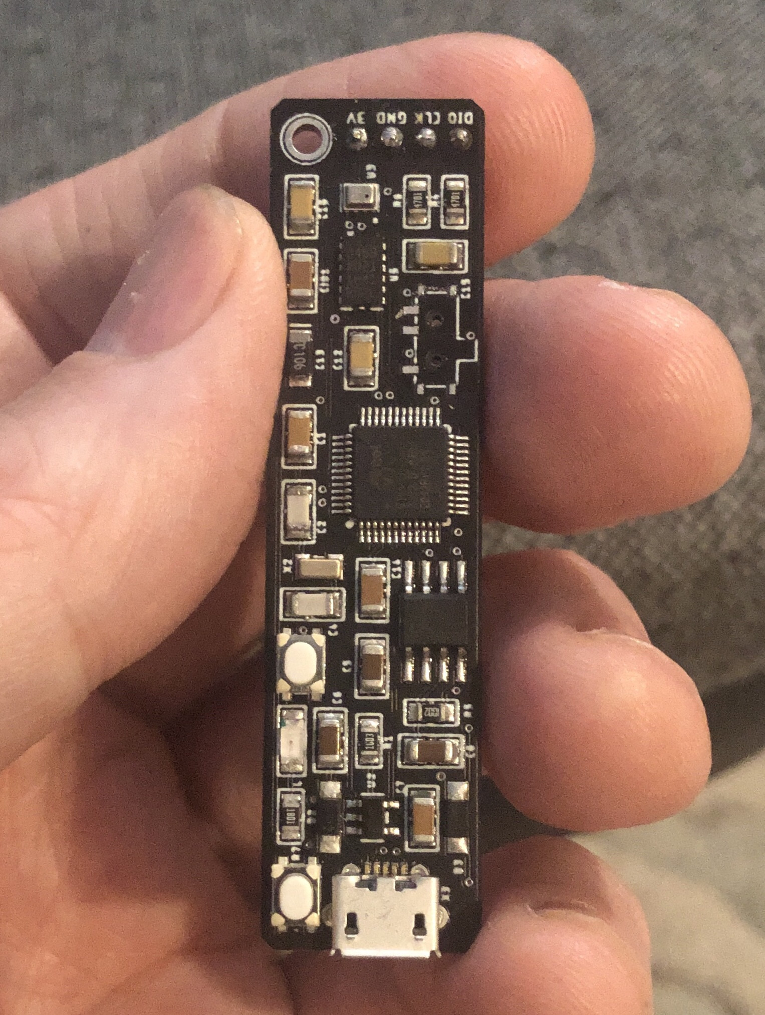
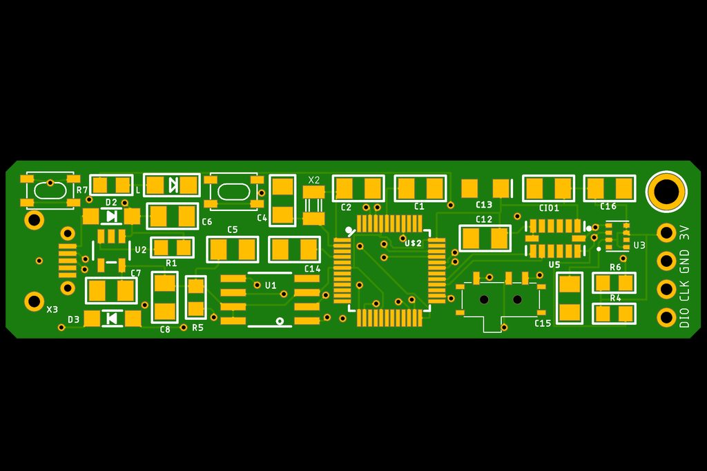
 obtuse spruce
My code is here https://github.com/mzero/pulsar-buddy/blob/master/pb/flash.cpp

GitHub
Contribute to mzero/pulsar-buddy development by creating an account on GitHub.
My problem was that I didn't do a good enough job of the bypass cap for the flash... and it made for too much ringing on the data lines.
slate pendant
- Are you sure 9600 is right - my IDE usually uses 115200
while (!Serial);is the sure fire way to wait for the serial connection to be up
thx for the tip and the router adress is 192.168.178.1 so I thought I'd go for the 9 for IOT stuff
obtuse spruce
Your network is almost certainly a /24... So you can't change the first three values
safe shell
Arduino supports DHCP, I've never fixed an IP address at the client side, just reserved IP addresses in the router based on MAC if I want predictable IP.
 stuck panther
I'm trying to make a pedestrian crossing project , but it keeps showing this error and I don't know why , if someone can help me I would be glad
north stream
Looks like you're calling pinMode() and digitalWrite() from outside any subroutines. You also have void loop() twice
stone spade
@obtuse spruce
Huh, I am not sure I understand the code you use.
Assuming these are the relevent parts
#include <initializer_list>
and
namespace {
bool flashBegun = false;
const std::initializer_list<SPIFlash_Device_t> additional_devices = {
// Settings for the Cypress (was Spansion) S25FL064L 8MiB SPI flash.
// Datasheet: http://www.cypress.com/file/316661/download
{
.total_size = (1 << 23), /* 8 MiB */
.start_up_time_us = 300, .manufacturer_id = 0x01, .memory_type = 0x60,
.capacity = 0x17,
.max_clock_speed_mhz = 4,
// Speeed must be limited due to bad routing on board (for caop. C7),
// 12MHz works in tests 100% reliably, but picking 4 just to be safe.
.quad_enable_bit_mask = 0x02, .has_sector_protection = false,
.supports_fast_read = true, .supports_qspi = true,
.supports_qspi_writes = true, .write_status_register_split = false,
.single_status_byte = false,
}
};
and
if (!flashBegun) {
if (!flash.begin(additional_devices.begin(), additional_devices.size())) {
critical.println("flash begin failure");
return false;
}
if (configuration.debug.flash) {
Serial.printf("flash length in sectors: %d\n",
flash.size() / SFLASH_SECTOR_SIZE);
}
flashBegun = true;
}
@obtuse spruce there are a lot of layers here. Any way to boil this down for someone who is not that advanced?
@obtuse spruce also, concerning the reliability and such due to your cap, do you think that could be an issue for me? I can run the erase sketch as well as the chip info and read sector sketches from the Library examples. It just fails wehn trying to format. I am wondering if I just bite the bullet and buy the same flash chip as used instead of fixing code if I will be in the same boat.
obtuse spruce
@stone spade - you can strip it down to:
const SPIFlash_Device_t AT25DF081A_device =
  {
    .total_size = (1 << 20), /* 1 MiB */
    .start_up_time_us = 10000,
    .manufacturer_id = 0x1f,
    .memory_type = 0x45, .capacity = 0x01,
    .max_clock_speed_mhz = 85,
    .quad_enable_bit_mask = 0x00,
    .has_sector_protection = true,
    .supports_fast_read = true,
    .supports_qspi = false,
    .supports_qspi_writes = false,
    .write_status_register_split = false,
    .single_status_byte = false,
  };


void setup() {
  ...
  flash.begin(&AT25DF081A_device);
  ...
}
I have no idea if the cap issue would be for you too - my electronic design skills are very new - so I didn't get my cap layout right? Did you think about the return loop length for the flash chip's bypass cap? In any event - just turning the .max_clock_speed_mhz down to 1 will tell you if that's the problem: If it works at 1MHz, but not at full (for an M0, that'd be 48MHz) - then it is probably the same issue.
If you want, I just pushed a small SPI Flash tester sketch: https://github.com/mzero/SPI-flashtest
GitHub
small Arduino sketch for testing SPI attached flash chips - mzero/SPI-flashtest
stone spade
Thanks for dumbing it down for me! I can work with that. I’ll test the speed too. By the way, what does your board do exactly? Some sort of sound manipulation?
obtuse spruce
It is a clock divider for synths: Given a tempo clock - it can clock out things like odd meters (13/8 anyone?) and tuplets for polyrhythms (how'z'bout 7:4 eighth notes?)
cedar mountain
Cool, it can probably do the Terminator theme's weird signature, then... https://slate.com/culture/2014/02/the-time-signature-of-the-terminator-score-is-a-mystery-for-the-ages.html

Slate Magazine
As The Terminator celebrates its 30th anniversary this year, the film continues to raise important questions. What are the risks to humanity of...
obtuse spruce
Cool article... The verdict was 13/16... Which happens to be one of my favorite meters and one I explicitly created that hardware for.
north stream
Now make a Blaster Beam...
stone spade
@obtuse spruce cool!
stone spade
@obtuse spruce Ok so I tried to add the code you suggested, but am getting this compile error:
'SPIFlash_Device_t' does not name a type'
any thoughts?
@obtuse spruce also on the SPI flash test you pushed, I'm getting compile errors on that too:
'class Adafruit_FlashTransport_SPI' has no member named 'getClockSpeed'; did you mean 'setClockSpeed'?
obtuse spruce
oh - meh -right I added getClockSpeed to the API of the library - and that isn't in mainline (yet!)
For the first problem, you'll need this include:
#include "flash_devices.h"
For the second - for now, just change this line:
original_clock_hz = flashTransport.getClockSpeed();
to
original_clock_hz = 48000000;
(never mind, it is in Hz - so code fix, fixed)
slate pendant
I am finally getting serial from my ESP but not the exactly expected??
this is happening at the same time the LED blinks for startup every couple seconds
also couldnt find out how to achieve this again, it randomly outputted after I tried to flash another try where it couldnt connect..?
slate pendant
I'm getting data again when the programmer is in UART mode?
yeah its rebooting all the time, no matter what programmer mode, the software reset doesnt work and it only gives serial output when the IDE fails uploading due to board restarting itself all the time
and its still just gibberish with a serial opened behind ._.
stuck coral
I dont see any messages from earlier if this is continuation of a conversation but do you have the right baud rate?
slate pendant
yes, in IDE set to 74880 and in Serial Monitor aswell.
chose this because the bootloader apparently outputs to this baud
stuck coral
ESP32 outputs at 115200
In the bootloader
74880 is a odd rate
But your code will set the baud, so as long as you have one shared between your board and monitor you're good to go
slate pendant
I just found this in one of the examples?
on the web I can only find the LED being connected to GPIO2
stuck coral
I thought you were talking about the serial connection
slate pendant
yes but it says it Serial.print() doesnt work when LED is active...?
slate pendant
removes all debug LED activity from sketch
trying to use the specific ESP8266WiFi.h
there's also ESP8266WiFiMulti.h but dont know what that does..
stuck coral
Allows for a list of wifi networks that the ESP can connect to instead of only one at a time. Not that it connects to multiple at the same time but if the first network cant be found then it chooses the second
slate pendant
ahh ok thx
there are major differences between the ESP Wifi lib and the arduino one, despite both working with the same device
I had it working before, long time ago but dont ask me how
back then the only part not working was the webhook request
nevermind the arduino library only officially supports arduino, what a surprise
stuck coral
There are, the ESP WiFi library is from the ESP IDF
slate pendant
finally found a good reference, will rebuild program from ground up tomorrow
https://arduino-esp8266.readthedocs.io/en/latest/esp8266wifi/station-class.html#start-here
night
thx for the help
stone spade
@obtuse spruce, thanks again. Still striking out.
with the changes I can now see the chip without libray modification., but I get the same:
Adafruit SPI Flash FatFs Format Example
Flash chip JEDEC ID: 0x1F4501
!!!!!!!!!!!!!!!!!!!!!!!!!!!!!!!!!!!!!!!!!!!!!!!!!!!!!!!!!!!!!!!!!!!!!
This sketch will ERASE ALL DATA on the flash chip and format it with a new filesystem!
Type OK (all caps) and press enter to continue.
!!!!!!!!!!!!!!!!!!!!!!!!!!!!!!!!!!!!!!!!!!!!!!!!!!!!!!!!!!!!!!!!!!!!!
Creating and formatting FAT filesystem (this takes ~60 seconds)...
Error, f_mount failed with error code: 13
and the flash test returns:
[FATAL] Failed to initialize flash chip.
obtuse spruce
Hrm... I'll look at code later... Have to go watch some Legend of Korra with my daughter now!
stone spade
@obtuse spruce Cool whenever. I appreciate your insights and thanks for sharing your Sunday with me 🙂
nova comet
@stuck coral any clue why Im unable to upload code that uses the arduino ble library to my uno? The error is:
Arduino: 1.8.10 (Mac OS X), Board: "Arduino/Genuino Uno"

WARNING: library ArduinoBLE claims to run on samd, megaavr, mbed architecture(s) and may be incompatible with your current board which runs on avr architecture(s).
/Users/user/Documents/Arduino/libraries/ArduinoBLE/src/utility/HCIUartTransport.cpp:33:2: error: #error "Unsupported board selected!"
 #error "Unsupported board selected!"
  ^~~~~
/Users/user/Documents/Arduino/libraries/ArduinoBLE/src/utility/HCIUartTransport.cpp:99:40: error: 'SerialHCI' was not declared in this scope
 HCIUartTransportClass HCIUartTransport(SerialHCI, 912600);
                                        ^~~~~~~~~
/Users/user/Documents/Arduino/libraries/ArduinoBLE/src/utility/HCIUartTransport.cpp:99:40: note: suggested alternative: 'Serial'
 HCIUartTransportClass HCIUartTransport(SerialHCI, 912600);
                                        ^~~~~~~~~
                                        Serial
Multiple libraries were found for "Adafruit_MCP23017.h"
 Used: /Users/user/Documents/Arduino/libraries/Adafruit_MCP23017_Arduino_Library
Multiple libraries were found for "Wire.h"
 Used: /Applications/Arduino.app/Contents/Java/hardware/arduino/avr/libraries/Wire
Multiple libraries were found for "ArduinoBLE.h"
 Used: /Users/user/Documents/Arduino/libraries/ArduinoBLE
exit status 1
Error compiling for board Arduino/Genuino Uno.

This report would have more information with
"Show verbose output during compilation"
option enabled in File -> Preferences.
hm
so
the library isnt compatible with non-built-in ble
nova comet
anyone know a library that can set up ble gatt on an external bt chip (HM-18)? Im running into errors with ArduinoBLE and with BLEPeripheral
my code has no errors but when i compile it shows me other issues with the library
 ripe flint
Is it possible to run this TFT screen in 8 bit mode, but still run the microSD card slot built in? https://www.adafruit.com/product/2050
cedar mountain
With a quick look at the schematic, I think you should be able to use the screen and the SD slot together in the same design, yeah, although perhaps not literally simultaneously, since they share some signals. Is there anything about 8-bit mode that worries you?
ripe flint
I was just concerned as the adafruit tutorial seem to suggest you could only use the SD card reader when the screen itself was in SPI mode
cedar mountain
Hmmm. It's possible that the hardware is capable of it, but the 8-bit display driver is not smart enough to know how to trade off chip-selects with the SPI driver automatically.
There may be some similar software subtleties in switching pin functions between SPI_CLK and LCD_WR dynamically... again, it should be possible at the hardware level but the driver might not implement it out of the box.
I'm just guessing there, though.
ripe flint
Thank you for looking into it, but I think I'll just play it safe and use an external sd card reader to avoid possible damage to the screen / it not working. I was hoping to just decrease the size of the project.
stuck coral
@nova comet its just a serial port, so there should either be another library, or minimal work just to use the standard serial library
 safe halo
How do I convert a Hex Number to the decimal equivelant Such as
HEX = 0x3E
DEC = 62
CHAR = <
 lone ferry
By hand? In code? From a string? @safe halo
safe halo
In code. I amwanting to convert the MAC address to an 18 digit number so I can use that as a unique ID number
lone ferry
What datatype is that MAC address in?
safe halo
Byte Array
  byte mac[6];
  WiFi.macAddress(mac);
OK, so it's not hexadecimal at all. 😉
safe halo
I do a print on each item and I am getting ```
0
111
40
119
143
60
But the Hex Numbers are
Serial Number = 24: 6F: 28: 77: 8F: 3C
The decimal should be
```024,111,028,119,143,60
So you do want it as a string with commas in between the decimal numbers?
safe halo
nope one continuous number as a string
lone ferry
char c[32]; sprintf(c, "%03d%03d%03d%03d%03d%03d", mac[0], mac[1], mac[2], mac[3], mac[4], mac[5]);
safe halo
That Worked Perfect. Thanks
 errant geode
Is there something like pin "expander", or "splitter", but for one pin? For example, i have multiple i2c devices and i want to connect it with prototyping cables, but i have only one scl and one sda pin on dev board?
 odd fjord

This is a cute half size breadboard, good for small projects. It's 2.2" x 3.4" (5.5 cm x 8.5 cm) with a standard double-strip in the middle and two power rails on both sides. ...

The SparkFun Qwiic Adapter can make any old I2C board or sensor a STEMMA QT / Qwiic-enabled one. This adapter breaks out the I2C pins from the JST SH connectors to pins that you can easily ...
Then use Qwiic cables/adapters

This 4-wire cable is a little over 150mm / 6" long and fitted with JST-SH female 4-pin connectors on one end and premium Dupont male headers on the other. Compared with the chunkier ...
north stream
@errant geode There's this I2C multiplexer that lets you hook multiple I2C buses to a single SCL and SDA pin https://www.adafruit.com/product/2717

You just found the perfect I2C sensor, and you want to wire up two or three or more of them to your Arduino when you realize "Uh oh, this chip has a fixed I2C address, and from what I ...
Or if you're just looking for the wiring bits, jerry's suggestions are good, or something like https://www.adafruit.com/product/874

These are like the fancy electronics equivalent of the wire nuts electricians use to bind wires together. They are a lot easier to use as well! Each block connector has a metal block inside ...
errant geode
Yeah, i mean something like breadboard, but smaller.
north stream
How about this? https://www.adafruit.com/product/2463

Add a micro-slice standard solderless breadboard to your Perma-Proto or other perf-board. This 4x4 point solder-less breadboard is a good way to add some solderless prototyping ...
Amusingly, the first time I saw the little humidity sensors, I looked at the picture and thought "what a wonderful teeny little breadboard!" but then realized that was just what the cover looked like. I was disproportionately thrilled to find the actual teeny breadboards existed.
errant geode
Yes, i am looking for pcb (more flat) but this mini breadboard is also good for my project, thank you 🙂
 mild mica
hi
slate pendant
my sketch is working 😳
the serial port "not working" seems to be a loose connection of my programmer in the USB port
now that I use the ESP WiFi library it kinda works.
I can see it in my router, although it does not display its IP adress or the hostname I set, even tho I recieved the hostname it has over serial.
Just this...
now so HOW does this webhook thing work...
slate pendant
can anybody please point me to a reference how I can make a webhook get request
I want to fire a signal when the webhook gets a post for about 5 seconds and dont want much network traffic...
I can only find examples for POST
safe shell
@slate pendant GET isn't inherently faster or less data than POST
nova comet
Hey is anyone available to help? Ive got an arduino hooked up to an HM18 bt chip, and im trying to set up BLE with the BLEperipheral library but im getting all sorts of issues. I think its the library that doesnt support my chip but if so, im not sure what library to use
slate pendant
@Chaos_02GET isn't inherently faster or less data than POST
I cant find any reference on how to DO a get in arduino tho.
Just with curl :/
safe shell
@slate pendant The low-level way is like this https://www.arduino.cc/en/Reference/WiFiClient or there's the HTTPClient library https://github.com/espressif/arduino-esp32/tree/master/libraries/HTTPClient
 royal lava
I am running into some problems with a stepper motor. If I slow it down it seems to skip around a little. at fast speeds it seems to work fine but when I slow it down to like 10 rpm or lower speeds its seems to take a few steps then bounce in place
slate pendant
just to make answering easier: what kind of info??
 blazing sierra
Hello I just joined the channel and I'm thinking about getting into arduino. I'm a comp sci major and I'm decent at coding but know nothing about hardware I'm wondering what's a good way to get started?
Should I get the official ARDUINO STARTER KIT MULTI-LANGUAGE? I'm trying to get something I can learn from and also get good starting tools
reef ravine
@blazing sierra do you have a project in mind or do you just what to become familiar with the hardware aspects in general?
blazing sierra
umm Nothing in particular yet but to be honest I was inspired to try this by people like Micheal Reeves and other youtubers so probably something stupid and cheap?
reef ravine
a starter kit maybe the way to go then, get some LEDs, some resistors, an LCD or OLED, some buttons, a relay maybe. what board were you considering?
blazing sierra
The Arduino Starter Kit is the ultimate educational solution for learning how to use the Arduino platform.
i was thinking about getting this because it has almost all of those things and teaches me a bit along the way too ahha
reef ravine
You'll learn to be very efficient with your code, 32K runs out very quickly 🙂
blazing sierra
Where does it say 32K?
reef ravine
the 328P chip on the UNO has 32K
blazing sierra
So if I wanted to do more I could just buy a new board or chip right?
reef ravine
there are other Arduino boards with more (or less) memory, higher clock speeds, etc
the kit looks to have a nice assortment of hardware
blazing sierra
So do you think that it's a good way to learn and is a good price for what it gives?
reef ravine
if you spent time on Amazon, eBay, Banggood, etc you could probably save a few dollars but you never know when you'll get a low quality clone part. It looks reasonable for genuine parts.
blazing sierra
right and this has tutorials online specifically for this kit
once i get through all the tutorials maybe I can come back here and get some project ideas haha
reef ravine
if you're familiar with C it should come to you fairly quickly "Arduino" is C++ with some hardware extensions
blazing sierra
I was taught C++ and C in college but it's been a while, I'm not really worried about the coding side of things
reef ravine
then welcome to Ohms Law 🙂
blazing sierra
Yeah that's kind of the part i'm worried about the hardware integration
reef ravine
it's low voltage, with reasonable care you won't release the "magic blue smoke", and this server can provide great support for basic circuitry questions
blazing sierra
Ok cool so I think I'm going to buy this
reef ravine
good luck! start with blinking LEDs, everybody loves blinking LEDs 🙂
(If i made a time machine friends and neighbors would yawn, put an LED on it - "wow that's cool!")
 scenic summit
anybody bought the elegoo kit with their third party arduino?
A parts list came with the kit, but information about each component didn't. How do I know if I need a resistor for some of the buttons? There's nothing on them that tells me required voltage.
gilded swift
Everything is usually 3.3V-5V on those kits
You should have got a project book with the kit
scenic summit
oh ok. Thank you. I saw someone using a 10K resistor and another using 330 on the same button. Wasn't understanding how they were figuring what they needed with no instruction to go on. No project book comes with the elegoo kit.
gilded swift
It’s usually based on current requirements
If they are using a 10K, it’s probably as a pull resistor
330 is usually current limiting resistor.
Not always but at least with LEDs
scenic summit
ok i'll go read about that difference. thank you so much for your help!
gilded swift
You’re welcome 😊
opaque hollow
Yep, a 10k resistor is used as a pull down resistor for the button. Search for: "Arduino Button Example".
ripe flint
Does anyone know if its possible to draw images to a tft LCD screen if its in 8 bit parallel mode?
I cant seem to find a library that supports it
reef ravine
it should be possible, what errors are you seeing?
ripe flint
I tried using the libraries recommended by adafruit, but its basically telling me to use SPI mode instead of 8 bit mode.
Error: ```error: no matching function for call to 'Adafruit_ImageReader::drawBMP(const char*, Adafruit_TFTLCD&, int, int)'
stat = reader.drawBMP(fileName.c_str(), tft, 0,0);
^
In file included from sketch\TouchScreen.h:11:0,
from D:\milkm\Documents\Arduino\Google_Calendar_Reminders\Google_Calendar_Mega_Airlift_TouchScreen_SD\Google_Calendar_Mega_Airlift_TouchScreen_SD.ino:19:
D:\milkm\Documents\Arduino\libraries\Adafruit_ImageReader_Library/Adafruit_ImageReader.h:99:19: note: candidate: ImageReturnCode Adafruit_ImageReader::drawBMP(char*, Adafruit_SPITFT&, int16_t, int16_t, boolean)
ImageReturnCode drawBMP(char *filename, Adafruit_SPITFT &tft, int16_t x,
^~~~~~~
D:\milkm\Documents\Arduino\libraries\Adafruit_ImageReader_Library/Adafruit_ImageReader.h:99:19: note: no known conversion for argument 2 from 'Adafruit_TFTLCD' to 'Adafruit_SPITFT&'
did you get this to work?
https://learn.adafruit.com/adafruit-2-8-and-3-2-color-tft-touchscreen-breakout-v2/8-bit-wiring-and-test

Adafruit Learning System
Color! Lights! Touch! 8-Bit! SPI! MicroSD Card! Pickles!
ripe flint
yeah. I can write to the screen, get touch inputs, etc.
I just cannot display images to the screen
ripe flint
from an SD card reader not attached to the display
reef ravine
can you get the reader to work by itself? (see the files that are loaded)
the SPI bus should be free for the reader to use
ripe flint
I believe the reader is working (although I'll go ahead and double check). the main issue Im finding is that most libraries rely on the internal Sd reader and then require the screen to be in SPI mode
reef ravine
may be a coding issue if you can read from the reader and drive the screen, you may want a library for the reader itself and use its methods
reef ravine
Open-source electronic prototyping platform enabling users to create interactive electronic objects.
Open-source electronic prototyping platform enabling users to create interactive electronic objects.
that library seems to handle external readers. then i'm not sure how you would move the file to the screen however
you're using Adafruit Color TFT Touchscreen Breakout v2?
ripe flint

Add some jazz & pizazz to your project with a color touchscreen LCD. This TFT display is big (3.5" diagonal) bright (6 white-LED backlight) and colorful! 480x320 pixels with ...
reef ravine
are you using pin 5 for CS?
ripe flint
no, im using pin 38 for sd's cs
reef ravine
so you have something like #define SD_CS 38 // Card select for shield use in your sketch?
ripe flint
yeah
reef ravine
and the whole thing is wired up for SPI now?
ripe flint
the external sd card is, but not the display
reef ravine
in spi both readers can hang on the bus, it should select your reader with the SD CS pin
i guess you tried that?
ripe flint
I think i might have mis-explained my problem.
Its not that I cant access the SD card or cant access the screen, its that I cant transfer images from the card to the screen via the GFX library.
Both the SD card and screen work fine, I'm just missing some software to let me use the 8 bit mode of the screen as well as being able to display images
reef ravine
you need 8 bit mode?
ripe flint
It would be preferable just so I can use the faster refresh rate.
reef ravine
ah, sorry for the rabbit hole then
ripe flint
No problem. You were trying to help and that's always appreciated.
 wraith glade
Hello everyone. I am making a project on sending email using an Arduino Uno and ESP8266 Wi-Fi module and I need some help here
I used the code given on the Circuit Digest website and added on the code for Grove LCD display given on it's official website there
The issue is that my Arduino/ESPN is stuck at Connecting WIFI and does not even bother proceeding to connect to my WIFI network over here
 vivid rock
@wraith glade it would help if you post your code. Easiest way to do this is using pastebin.com
wraith glade
Sure I could
Give me a while to post my Pastebin link here
@vivid rock Here's the link: https://pastebin.com/PUQx7wpW
Pastebin
Pastebin.com is the number one paste tool since 2002. Pastebin is a website where you can store text online for a set period of time.
This two links below are my original source website
How to send email with Arduino? Check this tutorial on how to connect Arduino with internet and send email using Arduino Uno and ESP8266 Wi-Fi Module.
Seeed Product Document
wraith glade
Help needed here ^
obtuse spruce
In your connect_wifi() function, you pass a timeout - and when you call it with the "AT+CWJAP..." string, you give it a 7000 ms timeout, since I expect that you expect it to take a while before the OK comes back...
However, you don't use the timeout value in your function at all... So the timeout in teh Serial1 object will be default, just 1000ms. Since your code, on timeout, will immediately resend the command again - and I'm not sure how the WiFi subsystem responds to that.... but in any event, after 6 tries, it exits - which is less than the intended timeout.
Try adding Serial1.setTimeout(t); to the top of connect_wifi()
 teal prism
How do you power an arduino nano with a breadboard power supply module? I cant use the usb port on the power module since I am hooking that up to a different arduino. Do I need to connect specific pins from the power module to the arduino nano to power it? is this even possible?
 shrewd wyvern
sure
connect the 5V output from the power supply to the 5V pin and Gnd to Gnd
make sure you have a 5V output before connecting it
you may fry the board
teal prism
5v output? how do i avoid frying the board
shrewd wyvern
that is output or input I guess
you can also use the Vin pin with a 7 to 12 V source
I think that way the power will go through a regulator
that will regulate it to 5V oe 3.3 not sure
The Arduino Nano can be powered via the Mini-B USB connection, 6-20V unregulated external power supply (pin 30), or 5V regulated external power supply (pin 27). The power source is automatically selected to the highest voltage source.
teal prism
Ah alright, so with the power module, I just hook up the 5v to 5v on the arduino and gnd to gnd, then the nano should be powered?
shrewd wyvern
yes
you won't have power in the usb port.. but I guess you are not using it (if you would be using it you would be powering it through it)
teal prism
yeah yeah, Im not using the usb port, alright anyways, thank you
shrewd wyvern
no worries good luck
gilded swift
You can hook up to the 5V pin
slate pendant
what does webhook code -1 mean again? :/
Got my esp to connect for a magical reason
slate pendant
nevermind, got my sketch to work
only thing "missing" is the relay opening because I dont really know wich pins are able to supply it
I set relay open to Pin 2 atm wich is also LED and TX...
 wooden bobcat
anyone have suggestions on attaching a usb keyboard to an arduino-type device? i know i need a usb host adapter of some type. is there a usb keyboard library? i'm doing a keyboard protocol converter and am looking at options. i've done one with ps2, but want to move to more available keyboards. thanks!
north stream
An Arduino can't act as a USB host, so you'll probably need something like this https://www.sparkfun.com/products/9947

This new version corrects the pin out for the GPX and RESET pins. The SparkFun USB Host Shield contains all of the digital logic and analog circuitry neces
cedar mountain
Some of them can, I think, like the Due.
wooden bobcat
@north stream @cedar mountain thanks.. hobbytronics in the UK has a breakout board solution that would work.. all of these cost more than the $10 a pi zero w costs. i'm going to see if i can port my code over. nothing is terribly timing dependent and the machine i'm bitbanging to isn't either.
 glossy sierra
What is a good beginner project that I can make more complex overtime? I have done all of the button and light and sensors basics just can’t honk if anything interesting to build with my new skills
stuck coral
Local home automation
Well idk how beginner that is but you can start with a light strand that reacts to something then you can add onto it and extend the idea to a whole home automation setup with a Pi as a controller and numerous devices
Towards the end you would be able to learn about collecting metric data from a low power sensor network via MQTT and storing the data into a database while acting upon certain conditions, could extend quite far from an inital starting beginner device
You could include lights, motorization, various sensors, learn about making ultra low power embedded devices, maybe even dip your toes in what it takes to send an update wirelessly to an Arduino
glossy sierra
Sounds good. I want it to be something that I can keep learning off of
 proven mauve
Anyone have any experience getting i2c multi master going?
proven mauve
Both chips are hooked up to each other and an eeprom over i2c. Both chips need to access the eeprom. One is the main part of the device and accesses the eeprom a lot, no problem. The other chip only does some backup functions like reading the eeprom and saving the read to sd card. The backup chip only does it's functions when the main chip sends it i2c commands to perform a backup function. Then the backup chip will hold a wire low (forcing the main chip into a standby loop that only displays some LED colors), waits a second to make sure the other chip has time to get stuck in the standby loop, then transmits over i2c to do it's backup functions with the eeprom chip. Once it's done, it releases the low wire letting the main chip go back to normal operation.
One of the backup functions reads bytes from the eeprom and writes then to SD, and one takes an sd save and writes a bunch to the eeprom. Often, the main chip becomes locked up when the backup does a read from eeprom (but not a write). It will be in it's loop doing nothing but displaying pretty LED colors, and it will freeze. Meanwhile the backup chip is able to complete it's job.
I'm trying to understand what could cause the main chip to just freeze up.
 violet pine
Can someone explain how arduino works and what language it uses?
obtuse spruce
@violet pine - Arduino is a family of small electronics platforms that you can extend with your own electronics and software to do a very wide variety of things. They are generally programmed in C++, using a set of very easy to use libraries that make working with the electronics bits (sensors, lights, motors, etc...) very easy.
Some boards can be programmed in a stripped down version of Python. Others can be programmed in a graphical block programming system called MakeCode.
violet pine
Could it be programmed in c#?
obtuse spruce
I don't believe so. There is no C# run-time environment that runs on them.
These devices are very small by modern computer standards - generally 100s KB of ROM (for program and static data), and 10s of KB of RAM.
violet pine
is there any good/not mind numbing things i can watch or read about the basics of c++?
 topaz compass
I haven't any presentations by spongebob, sorry
violet pine
dang
amber gulch
how do i connect 4 5v motors to a breadboard
slate pendant
as far as I know C# is very similiar to C++ in syntax and general appeal, its just that C++ is more a comiler language while C# is something like the .NET framework but only as far as I know.
The Arduino site has a big reference with examples for each operand and function it includes by default.@violet pine
how do i connect 4 5v motors to a breadboard
in parallel or ind Series?
@amber gulch
for each Motor a cable that runs to their + contacts and from each - contact a cable that ends in a line with the GND pin or the row "outside" of the breadboard labelled -
north stream
@proven mauve That's an interesting one. I wonder if the main chip gets interrupts or something on one of its I2C pins.
proven mauve
@north stream mmm, the one thing I understand is that i2c commands are sort-of interrupts themselves. Like, for the backup chip I set a type of onReceive() function to perform any time the chip's i2s address is referenced over i2c, and I don't have to run and sort of read() function like with midi
whenever that address is sent a command over i2c the backup immediately does the receipt function
but as far as interrupt function on the pin itself, I'm not tracking the main chip doing that. Unless it's in one of the libraries I'm using
So, next I'm going to try and make some sort of receive dump for the main chip just in case it needs an empty function to be happy if it thinks it got an i2c reference
If that doesn't work I haven't gotten any farther yet lol
oh
north stream
That makes sense to me, but I might do a little more breadcrumb debugging to narrow down what the main chip is doing when it freezes.
slate pendant
the ifttt webhook thing doesnt work anymore??
ifttt cant post to the webhook server they run
always getting bad request when trying to post Data in the json format
proven mauve
@north stream I'm fairly confident all it's able to do is run a loop updating a string of LEDs, it's trapped in a while loop, and the pin that controls the loop is being held low the whole time. It pushes out to some WS8212's, and it does it, but when that backup read transmission is going it freezes (and the LEDs look a little off). Using an adafruit rainbow() led function. The other times it's trapped in that loop it doesn't mind at all...
proven mauve
also... it doesn't always freeze lol. Its in the ballpark of %50
 green heath
I have a question about serial communication. why do some example projects use pin 2 and 3, instead of 1 and 0 marked for TX abd RX respectively for serial communication?
for example https://create.arduino.cc/projecthub/ruchir1674/how-to-interface-gps-module-neo-6m-with-arduino-8f90ad

Arduino Project Hub
In this project, I have shown how to interface a GPS module with Arduino UNO. The data for longitude and latitude is displayed on the LCD. By Ruchir Sharma.
north stream
GPIO 0 and 1 are tied to the on-board USB-serial interface to communicate with the host. While you can use them for your own projects, it means you can't use the serial monitor at the same time, and you would probably need to disconnect/disable whatever is hooked to them to download a new sketch.
green heath
oh right.
I havent yet checked the datasheet, but how do they achieve serial communication on the other pins then? Ideally I'd like to code in C but I am so far still looking around 😅
north stream
Good catch. The original Arduino only has one UART, the one on GPIO 0 and 1, so to send/receive serial data on other pins, you need to use software serial. There are a few boards that use the -PB version of the CPU, which has a second UART, as well as other boards with more UARTs.
green heath
oh well, so far it doesnt make sense yet. but you mentioned something about an onboard usb-serial interface. I can configure that one to communicate with a serial monitor, just using the arduino board and USB cable?
 warped gust
Can you have the serial monitor open and watch the data being sent to whatever device you have on the UART?
 neon flicker
Has anyone here set up a MSGEQ7 chip, I'm having some trouble reading the values and would really appreciate some help.
 tame totem
so im making a tank and i was using an ir remote to control it
i decided to switch to nrfl24l01 because the range wasnt enough and most of the time thd signal wasnt clear
i bought some settled it up and it worked
however when the tank is on the battery the system doesnt work. when i connect the tanks arduino nano to my pc it does work (goes forward etc) but without the pc connection it doesnt
i had bad experience with the module before so i decided to buy those adapters as well and did the cabling according to tutorials
the transmitter has a joystick to control the tank and my test proved that it worked fine
the tank is powered with a 850mah 2s lipo battery and the arduino nano has the + of the battery output commonly with my motor driver and turret servo motor in vin. the nrfl24l01 vcc is connected to the arduino 5v and the gnd to the common gnd the other components use
any idea on why it may not be working?
im new btw
north stream
@green heath Yes, you can hook things to the RX/TX pins and use them to talk to the Arduino's UART (the board has 1k decoupling resistors between the AVR chip and the USB-serial chip so they don't fight over it).
You can also write a sketch that sets the RX/TX pins as inputs, and then use the board as a USB-serial converter
And you can use the serial monitor to watch the outgoing data (but not the incoming data)
The MSGEQ7 just provides an analog output, so you'd connect that to an analog input. Then you can use the reset and strobe inputs to cycle through the different filter frequencies.
tame totem
the tank only receives data when the arduino is powered
through a cable
with a power bank
which is under powering the motor and the servo
but still working and goinf
going
with the battery the circuit still works but no data is received
can a 7.4v 2s battery handle a nrf24l01 + servo + 2 motors
north stream
That's determined by the current more than the voltage
neon flicker
@north stream I'm trying to feed a signal to the chip with a 3.5mm jack, and I'm using a code that shows values for all 7 bands but nothing changes
Even when I change the tone on the tone generator
 indigo quail
Does anybody know a good place I can learn Arduino C?
stuck coral
Just fyi we refer to to language in Arduino as wiring. Any good C resources will be a great start, along with arduino.cc which has a great code reference, and the many examples that already exist in arduino have great comments and really help you learn basic concepts.
blazing sierra
Hi I have some extremely simple arduino codebut for some reason it stops working a few runs, can someone help me find out why
stuck coral
Post the code in a pastebin for us, Im eating so someone might beat me to the answer
blazing sierra
Pastebin
Pastebin.com is the number one paste tool since 2002. Pastebin is a website where you can store text online for a set period of time.
cedar mountain
And you'll also want to describe what "stops working" entails.
blazing sierra
sorry new to this
the light is suppose to turn back on after a random amount of time but after the 3rd time I press the button, all lights stay off
cedar mountain
I think you might be running into integer overflow in winTime. Try changing it from an int to a long.
blazing sierra
yeah good call
obtuse spruce
which light is supposed to turn back on? topRed?
and - your switch is between the pin and +3.3V, yes? so HIGH is pressed?
or does it have a pull up, and the switch is to GND, so LOW is pressed?
amber gulch
can someone please help me connect 4 5v stepper motors to an arduino uno through breadboard i need it to make 4 arms for a robot
cedar mountain
You'll need some sort of motor driver add-on circuitry. Two of these should be able to handle 4 steppers, for instance: https://www.adafruit.com/product/1438

The original Adafruit Motorshield kit is one of our most beloved kits, which is why we decided to make something even better. We have upgraded the shield kit to make the bestest, easiest way ...
amber gulch
i have a motor driver for each motor
amber gulch
@cedar mountain
cedar mountain
What kind?
amber gulch
umm
@cedar mountain
sorry this is really urgent sorry if i ask 50 questions
im really new to aruino but i need 4 motors that move individually when i tell them to
cedar mountain
Do you have a tutorial or example for your motor driver that you can start from, just with one stepper at first?
amber gulch
ive found examples to do one
but then it uses up all the holes on the uno
so idk where to go from there
amber gulch
@cedar mountain sorry for pinging again, but this is really urgent and i urgently need help :((
tame totem
can a 7.4v 2s 850 mAh battery handle a nrf24l01 + servo + 2 motors
 lone nimbus
hi everybody
amber gulch
mr ewewerethefool do u know how to attach 4 28byj-48 motors to an aruino uno with the driver modules?
lone nimbus
are you talking wiring or writing a sketch?
lone nimbus
what are you trying to achieve
amber gulch
i need to make a robot thing
that uses motors to rotate its arms
but they move individually
lone nimbus
show me what you got
amber gulch
i dont have anything lol
lone nimbus
thats gonna be a problem
lone nimbus
no board? no motors? no wire?
amber gulch
ohhh
i have that
i have uno board
and breadboard
male to male, male to female, and female to female wires
amber gulch
theres no intrusctions
its just like
the basic arduino equipment
omg thats weird
lemme get better picture
lone nimbus
im not going to write your project for you if that what you are asking
amber gulch
yeah ik
i just have no idea how to connect 4 motors to my uno using breadboard and stuff
lone nimbus
dude. those elegoo kits come with a cd with all the sketches you need to get started
amber gulch
im sorry idk how to do this
amber gulch
do u know how to connect 4?
amber gulch
yeah ik but i need to connect 4 of those
amber gulch
lol sorry
tame totem
ok i cant find it ill search more
amber gulch
nah u dont have to search too hard if youcant find it dw about it
tame totem
the war thunder match was going to be trashy anyway
lone nimbus
I'm needing some help with my project if anyone is available to help. I am trying to gather data from a DHT11 using and ESP8266 and I am trying to post the data to mysql database on my raspberry pi over wifi. i found an example using a bme280, and I am trying to adapt it to my needs, but im having trouble getting it sorted out
Build an ESP32 or ESP8266 client that makes an HTTP POST request to a Raspberry Pi LAMP server (Linux, Apache, MySQL, PHP). The RPi has a PHP script to insert and visualize your data.
tame totem
the driver has in1 in 2 etc written on it right
amber gulch
who
lone nimbus
i have one error message
sketch_aug06a:88: error: 'dht' was not declared in this scope

                           + "&location=" + sensorLocation + "&value1=" + String(dht.readTemperature())

                                                                                 ^

exit status 1
'dht' was not declared in this scope``` //Check WiFi connection status
if(WiFi.status()== WL_CONNECTED){
HTTPClient http;
// Your Domain name with URL path or IP address with path
http.begin(serverName);
// Specify content-type header
http.addHeader("Content-Type", "application/x-www-form-urlencoded");
// Prepare your HTTP POST request data
String httpRequestData = "api_key=" + apiKeyValue + "&sensor=" + sensorName
+ "&location=" + sensorLocation + "&value1=" + String(dht.readTemperature())
+ "&value2=" + String(dht.readHumidity()) + "";
Serial.print("httpRequestData: ");
Serial.println(httpRequestData);```@lone nimbus what is in the rest of your code -- you have not configured the dht sensor.
lone nimbus
  #include <WiFi.h>
  #include <HTTPClient.h>
#else
  #include <ESP8266WiFi.h>
  #include <ESP8266HTTPClient.h>
  #include <WiFiClient.h>
#endif
#include <DHT.h>
#include <Wire.h>


#define DHTPIN 2    // Connect to ESP8266 GPIO2 pin
#define DHTTYPE DHT11
// Replace with your network credentials
const char* ssid     = "";
const char* password = "";

// REPLACE with your Domain name and URL path or IP address with path
const char* serverName = "http://192.168.3.103/post-espdata8266.php";

// Keep this API Key value to be compatible with the PHP code provided in the project page.
// If you change the apiKeyValue value, the PHP file /post-esp-data.php also needs to have the same key
String apiKeyValue = "tPmAT5Ab3j7F9";

String sensorName = "DHT11";
String sensorLocation = "Front Porch";

/*#include <SPI.h>
#define BME_SCK 18
#define BME_MISO 19
#define BME_MOSI 23
#define BME_CS 5*/

// #define SEALEVELPRESSURE_HPA (1013.25)

/*Adafruit_BME280 bme;  // I2C
//Adafruit_BME280 bme(BME_CS);  // hardware SPI
//Adafruit_BME280 bme(BME_CS, BME_MOSI, BME_MISO, BME_SCK);  // software SPI
*/
void setup() {
  Serial.begin(115200);

  WiFi.begin(ssid, password);
  Serial.println("Connecting");
  while(WiFi.status() != WL_CONNECTED) {
    delay(500);
    Serial.print(".");
  }
  Serial.println("");
  Serial.print("Connected to WiFi network with IP Address: ");
  Serial.println(WiFi.localIP());

  // (you can also pass in a Wire library object like &Wire2)
/*  bool status = bme.begin(0x76);
  if (!status) {
    Serial.println("Could not find a valid BME280 sensor, check wiring or change I2C address!");
    while (1);
  }*/
}

void loop() {```where did that code come from -- it is missing something.
lone nimbus
i used the code from the project linked above
but i am trying to use a dht11 because i do not have a bme280 on hand
Build an ESP32 or ESP8266 client that makes an HTTP POST request to a Raspberry Pi LAMP server (Linux, Apache, MySQL, PHP). The RPi has a PHP script to insert and visualize your data.
just the one error
odd fjord
ah ok -- you need some configuration like this ```/#include <SPI.h>
#define BME_SCK 18
#define BME_MISO 19
#define BME_MOSI 23
#define BME_CS 5/
// #define SEALEVELPRESSURE_HPA (1013.25)
/*Adafruit_BME280 bme; // I2C
//Adafruit_BME280 bme(BME_CS); // hardware SPI
//Adafruit_BME280 bme(BME_CS, BME_MOSI, BME_MISO, BME_SCK); ``` but for the dht11
just a minute -- looking for an example
lone nimbus
#define DHTPIN 2    // Connect to ESP8266 GPIO2 pin
#define DHTTYPE DHT11 ```i have it defined already
i am using DHT.h library included in IDE
i know
dang
i forgot a bit
i smell what you are stepping in
odd fjord
you need dht DHT11; as well after those defines

Arduino Project Hub
This tutorial will show you how to use DHT11 with Arduino. By Arca_Ege.
How to measure temperature and humidity with the DHT11 and an Arduino. Diagrams and code are provided to display readings on an LCD or the serial monitor.
I don;t see where you actually read the sensor either -- from the second example int chk = DHT.read11(DHT11_PIN);
odd fjord
out of my "comfort zone" good luck
amber gulch
does anyone know how to connect 4 28byj-48 motors with driver modules to arduino uno
lone nimbus
'''httpRequestData: api_key=tPmAT5Ab3j7F9&sensor=DHT11&location=Front Porch&value1=19.00&value2=60.00
HTTP Response code: 200
'''
response code 200 is supposed to mean all good, but no data is added to mysql database. shouldn't i get an error message somewhere in mysql so i can troubleshoot?
north stream
@amber gulch The same way as one motor, just use 4 I/O pins for each one, and parallel the power and ground wires.
north stream
I prefer not to DM
north stream
Did you get one motor working?
amber gulch
yeah
but i ran out of places to put wires in the actual arduino
will i have to use the one with the mini breadboard on top of it?
north stream
You don't have to, but you will need some method for joining wires. If you have a breadboard, you can use it.
amber gulch
im sorry if i sound spammy and desperate this is really urgent
wait so
if i use that thing
can i connect them all to that
and then connect that to the uno?
@north stream ?
north stream
You've been working on this for days, why is it really urgent to build a robot arm now?
Yes, you can use the breadboard to connect multiple things together.
amber gulch
nah i was asking for a few days but i didnt get an asnwer
north stream
Many people have replied to you
amber gulch
yeah but im really stupid idk how this works
north stream
We all start out as beginners
amber gulch
im sorry for being spammy the past few days
so yk these numbers that the wires are connecteed to
at the top
does it matter which numbers its connected to?
or is that just so i know which pins to mention in the coding
north stream
The code you run should have the pin numbers in it, and they should match the ones the the motor board is connected to.
amber gulch
alr
so all the pins are the same/
@north stream when im done can i send you a photo so you can check if its good?
north stream
I'm not sure what you mean when you say "all the pins are the same". The power pins will be shared, but the data leads should be separate for each motor you want to control individually.
amber gulch
i mean like
if i put something in pin number 1
and the same thing in pin number 12
will it change the power draw or something?
or is it the same
im really sorry for wasting ur time with dumb questions
north stream
You'll have to be clearer. Do you mean a wire from GPIO pin 1 to GPIO pin 12? If so, that's a bad idea. Do you mean plugging two stepper drivers into the same GPIO? Or since you mention power draw, perhaps you mean something about the power supply?
north stream
Many companies offer prototype shields, they are not all the same. Asking if I know it doesn't help me help you, specific questions are a better idea.
amber gulch
umm
thats what mine says lol
idk what company mine is
mine looks like the adafruit on tho
so you know the numebsr are the top
if i put something in hole 0
and somethign in whole 6
*hole
will it be the same?
north stream
Ah, that's the AdaFruit protoshield
amber gulch
yeah
north stream
When you say "will it be the same", what are you asking?
north stream
Yes, those are the data wires
north stream
You already asked that, and I explained that you can use different pins (in fact, you will have to, if you want to run the motors independently). You will have to modify the code to match the pins you use.
amber gulch
yeah but i didnt understand it lol
north stream
If you don't understand something, asking the same question again is unlikely to help.
amber gulch
im sorry
yk how this stops at 13
but theres still holes after it
do those holes work the same or nah?
north stream
Those holes are for different purposes, but there are six more GPIO pins on the other side (A0 through A5), you can use those too.
north stream
Yes, those pins support analog in, but they can also act as digital in and out, like the digital-only pins.
Note that digital 0 and 1 are special, they're the serial link the host uses to communicate with the Arduino
north stream
You can plug your motors into the analog pins, but you probably do not want to plug them into digital pins 0 and 1.
amber gulch
can i plug two plugs into digital 2 and 3 and then another two into analog 0 and 1?
or will that not work
north stream
Yes, that's fine.
amber gulch
oh ok nice
oh and you know how theres a cap between 7 and 8
can i put two in that 6 and 7 and then the other two in 9 and 10
@north stream i saw this code for 1 stepper motor
defining the stuff
can i name STEPPER_PIN_1 to 1STEPPER_PIN_1 and 2STEPPER_PIN_1 to differenciate between the two motors?
north stream
Yes, but you don't want to use a digit as the first character of your #define so you will be better off with something like STEPPER1_PIN_1
 pine bramble
How do I write something to a SD card using the SD card lib? Ping me
errant geode
Is it possible to use D9 and D10 on esp8266 d1 mini? Becouse these pins are not exposed. Can i solder pins to them or these pins are used to something else and better to not use them?
obtuse spruce
@pine bramble Using the SDFat library? Just follow the ReadWrite.ino example.
obtuse spruce
just open it for write, like in that example.
pine bramble
Its not working
obtuse spruce
well - for starters, if you run that ReadWrite.ino example - does that work?
pine bramble
wait
obtuse spruce
oh - and did you format the medium?
obtuse spruce
Is there a file system on the SD card already?
obtuse spruce
OH.... well..... You need to do that first - you can either stick the card in your computer and format it, or you can run the SdFormatter sketch (also in examples)
(Quick question: Is this an actual SD card, or is it a SPI Flash memory used with SDFat?)
obtuse spruce
when running SdFormatter?
pine bramble
There's no file named that
obtuse spruce
Oh - let's back up a bit - which library are you using? SDFat?
obtuse spruce
Gotcha - So yes, that library doesn't support formatting. You'll have to format the card in your own computer (assuming you've got an SD card slot on it...)
obtuse spruce
(You can switch to https://github.com/adafruit/SdFat -- which is the one I use - it has the same API (basically), and does have the SdFormatter example (and formatting) support.)

GitHub
Arduino FAT16/FAT32 Library. Contribute to adafruit/SdFat development by creating an account on GitHub.
pine bramble
Ok
obtuse spruce
Formatted! excellent - now does the ReadWrite sketch work?
pine bramble
Waittttt
obtuse spruce
holds breath....