#help-with-arduino
1 messages · Page 62 of 1
 pine bramble
 north stream
And the extern declaration in the .cpp file didn't work?
Oh, if you instantiated it in setup() that probably won't work, you may need to make it a global (but not static) variable
 proven mauve
I tried adding this to the .cpp: extern MidiInterface MIDI
but
'MidiInterface' does not name a type
then tried
extern class MIDI
but
a storage class can only be specified for objects and functions
north stream
The "does not name a type" error may mean you need to #include the right header file
pine bramble
nis-a/sundial_v2_breadboard_version/dial_bread_sketch.cpp#L365
This'd be a lot easier to communicate without a seekrit repository.
pine bramble
Plus that bodger knows a lot more than I do on a blistering variety of subjects. ;)
proven mauve
lolol, you're all gurus compared to me 😄
@north stream https://github.com/SandwichRising/Sundial/

GitHub
Contribute to SandwichRising/Sundial development by creating an account on GitHub.
the inputsOutputs.cpp is the one throwing the error, it doesn't know what the MIDI object is. I tried ```#include <Arduino.h>
#include <MIDI.h>
#include <USB-MIDI.h>
#include "globals.h"
#include "inputsOutputs.h"
#include "midiControl.cpp"
#include "memoryControl.cpp"
extern MidiInterface MIDI```
north stream
Where is MIDI declared in the .ino file? I don't see it.
proven mauve
with the MIDI.h and USB-MIDI.h I'm frustrated it doesn't know why it would do the name a type error unless I'm wrong in guessing that it's a MidiInterface
in the .ino it's in the setup loop as: MIDI.begin(MIDI_CHANNEL_OMNI); MIDIUSB.begin(MIDI_CHANNEL_OMNI);
pine bramble
I'm seeing so many scope errors. ;)
north stream
I see the MIDI.begin() but I don't see where MIDI is declared.
proven mauve
oops, I guess that's not really where they're initialized right? In midiControl.cpp they're originially initialized as ```USING_NAMESPACE_MIDI;
typedef USBMIDI_NAMESPACE::usbMidiTransport __umt;
typedef MIDI_NAMESPACE::MidiInterface<__umt> __ss;
__umt usbMIDI(0); // cableNr
__ss MIDIUSB((__umt&)usbMIDI); //names the object MIDIUSB
typedef Message<MIDI_NAMESPACE::DefaultSettings::SysExMaxSize> MidiMessage;
MIDI_CREATE_INSTANCE(HardwareSerial, Serial1, MIDI)```
pine bramble
The very act of splitting off your .ino into a .cpp exposes them all.
north stream
Erf, I'm unused to including .cpp files, I usually split the shared stuff (like typedef) in to header files and include those.
pine bramble
@north stream it looked like MIDI was declared in the library's .CPP (which I thought was odd).
proven mauve
In my last project I split EVERYTHING into .h files, and then did #includes and was able to control everything, bring it in when I wanted. But I felt dirty doing it, like someone would later shame me lol
pine bramble
I would take your simplest working version (in a monolithic .ino file) and rename it to .cpp, and create an empty .ino file.
Then work (hard) to get that to compile.
Once that's working as it should, you can then think about other files.
The empty .ino only needs a comment to keep it open. Maybe not even that.
pine bramble
The reason is: Arduino IDE tries to be helpful, but once you graduate to more than just the .INO you need to address things the compiler (and the pre-processor, cpp) is doing to your code.
In C you generally have to declare a function before using it, and also define it.
So-called 'forward' declarations can bend that rule.
north stream
Basically, you need typedef MIDI_NAMESPACE::MidiInterface<__umt> __ss; again before you can refer to MidiInterface such as in your extern declaration. The idea of shared .h files is to avoid having that typedef twice, just re-use it in more than one module.
In plain C, the distinction is little clearer with declarations in the header files and definitions and action code in the the C files, but in C++ (and Wiring), the distinction is a little muddier, as often a bunch of action code ends up in the header file as part of a class definition.
pine bramble
The breadboard version compiles by error-masking important things; it's missing files and whatnot.
(refers to the non-present contents of memoryControl.h for example)
memoryControl.h:27: int pullEepromByte (byte diskAddress, int byteAddress, byte qtyBytes) ;
That's referred to in the breadboard monolithic ino file. ;)
I unmasked the error in compilation (scope, whatever) simply by moving the loop() to the end of the file.
Doing so exposes the fact that pullEepromByte isn't even present (at all) in the breadboard .ino.
Yet it compiled, initially. ;)
So this is just C compiler stuff. Basics.
When I get messed up, I start with a blank file and add stuff to it.
If the 'aha' moment happens early, I can sometimes reuse the old code, by editing it.
(I never learned C++ at all, except a tiny bit through osmosis from encountering it in Arduino libraries and code)
proven mauve
That's really odd, nis, it's in there, down below //pull bytes from an exernal eeprom chip over I2C, provide I2C address, address of byte(s) needed, qty of bytes to pull (either 1 or 2) //does using int return solve the problem of being able to pull multiple bytes? int pullEepromByte(byte diskAddress, int byteAddress, byte qtyBytes) { int rdata = 0; if (qtyBytes ==1 || qtyBytes == 2) { //only transmit if the request is for 1 or 2 bytes Wire.beginTransmission(diskAddress); Wire.write((int)(byteAddress >> 8)); // MSB Wire.write((int)(byteAddress & 0xFF)); // LSB Wire.endTransmission(); Wire.requestFrom(diskAddress,qtyBytes); if (Wire.available() == 1) { rdata = Wire.read(); } else if (Wire.available() > 1) { byte high = Wire.read(); byte low = Wire.read(); rdata = word(high,low); } } return rdata; }
that was saved before I did any splitting up, so it shouldn't reference any outside files. That's really odd
pine bramble
that's in memoryControl.cpp
proven mauve
right, after the split
the monolith breadboard is a stand alone file, doesn't need any other files with it
pine bramble
sorry my bad it's in there.
proven mauve
no worries! I did a double take tho lolol
pine bramble
well it's good that you knew. ;)
proven mauve
@north stream got down the rabbit hole a little farther but it's frustrating how little I know to solve some of these issues. Just to try and make it easy to test, I went to typedef MIDI_NAMESPACE::MidiInterface<__umt> __ss; extern MidiInterface MIDI; but then I get thrown '__umt' was not declared in this scope and I'm pretty out of my league now, working with library references
that file #includes both MIDI dependencies before that
north stream
Looks like I guessed wrong as to which declaration you needed: that typedef is the one for __ss, you'll need wherever the declaration for MidiInterface itself is.
proven mauve
I see
that gives me something to look into
I appreciate the help guys! Bedtime for me though. You'll prolly hear from me this week as I try to muscle my way thru the split lol
Projects like this make being out here a lot more manageable lol. Time goes by pretty quick
Thanks again, talk to you guys soon!
pine bramble
You're welcome.
Stuff like this can take me weeks to sit down and code for; the solutions often come quickly but thinking about it won't operate my computer's keyboard, to transcribe (or debug) the ideas.
🛩️ 🛩️
 verbal path
you could also tack a wire to the lower side of the CHG LED and monitor that digitally
I'm trying to get information when CHG LED is lit. Which side of the CHG LED would be the "lower side".
I'm using a Feather nRF52840 Express
 safe shell
Do you have a meter? If not, may have to load up the PCB drawings for the board from Github to see how it's laid out.
 cedar mountain
Looks like it's the pad away from the edge of the board.
 rancid patio
For someone learning electronics without any big projects in mind, what kind of capacitors are good to have? I want to buy an assortment but want a wide variety that are going to be in range with most of my learning. What is this range that I should get?
 stuck coral
They sell nice cap kits I find pretty awesome
cedar mountain
Most common would be 0.1-10uF, I'd say. There are often "kits" of capacitors and resistors of a bunch of different values, specifically to stock up for random uses.
verbal path
@cedar mountain we talked a few weeks ago about using capacitive fabric for this build. I've added a small woven capacitive fabric to my project, but when I try to do touchio.TouchIn(board.A5) it tells me I need a pulldown on the pin? What do I do?
cedar mountain
I'm not familiar with the touch stuff specifically, but a pulldown in general is a resistor between the pin and ground, typically in the vicinity of 10k, but it may vary with the specific use.
verbal path
Ok, I guess once I get my 3d printer up and running again, I'll have to see how I can make it fit
I saw today that there's a Feather nRF52840 Sense that has a acce/gyro built in. Might've been easier to do things that way in some form
cedar mountain
One reference here says 1Mohm is suggested in this case.
verbal path
Yeah, that's the error message I got. is it a 1M resistor?
cedar mountain
Yes
rancid patio
Thanks. I'll try to aim for 0.1-10uF.
verbal path
Where would I solder the resistor?
cedar mountain
Between A5 and ground, I'd assume.
verbal path
Ok, i think that makes sense. I haven't done a ton of electrical work so I'm asking very basic questions 😬
 visual steeple
Hey all, I have a project i've been working on using an Uno that I want to move to using a teensy. I'm using a couple of sensors that require 5v Vin that so far I've been supplying just from the arduino itself. Since the teensy only has 3.3v out, I'm going to need an external 5v supply. Can I just run both the teensy and sensors off the same supply and use that as the analog reference, or should i get a good external reference chip to get accurate voltage readings? sorry for the rambling; I discovered this was going to be a problem when I used the 5v out from the arduino to power my sensors and the teensy returned really inaccurate readings
 reef ravine
@visual steeple looks like the teensy will accept only 3.3v on analog inputs, what do your sensors put out?
visual steeple
up to 5v but i only care about 0-2.8v, so 3.3v input is fine
i didn't know about aref prior to this and now i'm wondering if my sensors will put out different readings even on the arduino i've been using, if i just switch to another power supply or computer
reef ravine
do not apply more than 3.3v to AREF
when you used the arduino +5v, did you also connect ground?
visual steeple
yea
i thought the readings look off, and used a pot to confirm
a pot powered from the arduino, set at 0 doesn't read 0 on the teensy
reef ravine
and the teensy and arduino share ground?
reef ravine
not many 3.3v boards tolerate 5v, most pins do on the teensy looks like
visual steeple
analogRead on the teensy just returns 1023 at >3.3v so i thought it was good enough for my needs
reef ravine
sounds like normal behavior, do you get readings now?
visual steeple
one sec i had cleaned up for the night haha
a lot better, thanks!
so i guess i'll just power my sensors from 5v and ground everything+teensy on the same rail
thanks again 🙂
reef ravine
yes, everything needs a common reference. happy hacking!
visual steeple
the teensy is still reading 1-2 with the pot at 0, but im guessing that's just cause it's not exactly 0v?
reef ravine
1/1023 , just noise
visual steeple
fair
last q: for what applications would one use an external reference chip then?
reef ravine
say you needed to precisely measure 1.00 v, the power supply and the internal references have tolerance, an external ref is designed to be exactly a voltage regardless of temperature, input voltage, etc
your measurements are only as accurate as your reference
visual steeple
makes sense, thank you again!
reef ravine
you are welcome!
proven mauve
I'm constantly having to reflash the bootloader to a breadboarded ATmega32u4 becuase the programmer stops responding over usb. Sometimes it works all day, sometimes I need to reflash after only working for 2 or 3 usb flashes. Any ideas on an easy solution?
 clever bramble
have u tried changing everything in tools menu to your board?
 forest bridge
Is it possible to make an Arduino beep a buzzer with out a bread board?
proven mauve
@clever bramble yep, just sometimes it stops being able to communicate with the programmer. A few times a day. Then when I reflash the bootloader onto it it's fine again
forest bridge
ok thanks
clever bramble
@proven mauve idk then, i have same problem
north stream
@proven mauve @clever bramble There are a bunch of possibilities, and the fix depends on what's actually happening. It could be that it re-enumerates, and then appears as a different USB device, it could be that the USB device is hung, so data doesn't get through. It could be that it re-enumerates but as a different (non serial) device. It could be that it stops appearing as a USB device at all. It could be a reset issue. It could be a bootloader issue.
proven mauve
@north stream thanks, I'll try to pay attention to those as I work. I think the usb still works for midi when it happens, but I'll need to pay attention
north stream
Ah, that's an important clue!
verbal path
@cedar mountain I wired up the CHG led to a digital pin & it was working great yesterday. Today it isn't working anymore :(. The value from the pin is always outputing TRUE
I'm not seeing the LED light up when charging anymore either 😬
I had it connected to D13 & the direction was set to "INPUT"
cedar mountain
Silly question, are you sure that the battery is actually charging? It might simply be fully charged already.
verbal path
I am sure the battery isn't fully charged
The CHG led isn't turning on at all
I have a second, untouched board that lights up fine with the same usb, charger, and battery
cedar mountain
Can you disconnect it from the D13 pin? If that were somehow outputting high instead of being an input, that might explain the symptoms.
verbal path
disconnecting it from the D13 pin showed no change in behaviour
cedar mountain
Odd, I don't have a good explanation for what happened, given the information so far.
 lament epoch
Hello I have an Arduino Mega and a Windows Computer, on the computer I am running Chrome browser over a local server on a website I built , I would like to trigger the Arduino from the website , what is the best way to approach this?
proven mauve
@lament epoch from what I hear people like to use modules like an ESP32 or ESP8266 to connect to the wifi and monitor things like website changes. They're microcontrollers with built in wifi
I've got a problem in my code I've narrowed down to this function... int pullEepromByte(byte diskAddress, int byteAddress, byte qtyBytes) { int rdata = 0; if (qtyBytes == 1 || qtyBytes == 2) { //only transmit if the request is for 1 or 2 bytes Wire.beginTransmission(diskAddress); Wire.write((int)(byteAddress >> 8)); // MSB Wire.write((int)(byteAddress & 0xFF)); // LSB Wire.endTransmission(); Wire.requestFrom(diskAddress,qtyBytes); if (Wire.available() == 1) { rdata = Wire.read(); } else if (Wire.available() > 1) { byte high = Wire.read(); byte low = Wire.read(); rdata = word(high,low); } } return rdata; }
If I run that function, afterward my MIDI over usb bogs down, and will hang the program for around .25 seconds every time it attempts to perform a midi send over usb. The midi sends are no longer received by the computer either. And all it takes is running that function once and the device can't recover until after a reset.
I am using this library to send midi over usb: https://github.com/lathoub/Arduino-USBMIDI

GitHub
Allows a microcontroller, with native USB capabilities, to appear as a MIDI device over USB to a connected computer - lathoub/Arduino-USBMIDI
unfortunately it doesn't have a .flush command, I'm wondering if that would fix the issue. But, it's the only library that mimics the standard MIDI Library, so that my serial MIDI and USB MIDI all use the same commands/syntax
If I stop using that function, the problem never occurs. If I comment out usb midi sends, the problem never occurs
lament epoch
Hello, i'm following this tutorial: https://maker.pro/arduino/projects/learn-how-to-enable-communication-between-an-arduino-and-web-browser, and I get stuck at the last step with the ardunio sketch that uses #include <VSync.h> , i get ```
compilation terminated.
exit status 1
VSync.h: No such file or directory```
I installed the Vsync library for processing, but im not sure where to get the file for VSync.h and which folder to place it , for the arduino IDE to use it. Any Ideas?
proven mauve
@lament epoch is that library compatible with the board you're working with? I'm not at a pc but to me that sounds like a base file for the library itself, and if the library is installed I would expect it to be there. Take that with a grain of salt though, I haven't used that lib
north stream
Where did you find the vsync library? How did you install it?
pine bramble
helo my pigpio on raspberry pi 4 have nott a toot have can i get a root to pigpio
sorry *root not noott
can someone help me
north stream
That question might be a better fit on #help-with-linux-sbcs or #help-with-circuitpython : pigpio is not really an Arduino feature.
 severe umbra
I dont wanna get into details here with what the blackbox is but i am trying to control it with pwm off the arduino but it requires more power than the arduino can put out so i have a battery setup. Last I asked I would then need a transistor to control the power flowing through. I have set it up like this:
my code is really only just:
int pin = 6;

void setup() {
  pinMode(pin, OUTPUT);
}

void loop() {
  analogWrite(pin,255);
}
is this all correct or did i misunderstood something
 molten maple
What do you mean by "it requires more power than the arduino can put out"? Do you mean it requires more voltage?
molten maple
have you linked the common grounds together? is the black box also separately powered as well as this apparent PWM input into the black box?
severe umbra
linked Common grounds together? - as in if all are connected to ground?
molten maple
yea both your transistor ground, arduino ground and battery ground linked together?
severe umbra
yeah they are
molten maple
ok cool
also note that the way you have it is that the PWM signal would probably be somewhat inverted by your transistor arrangement
molten maple
well the transistor will pull the 9V down to ground whenever the arduino pin is high
assuming that you've connected the +ve side of the battery to the resistor, although it is drawn with the negative connected to the resistor
severe umbra
Oh yh thats me being too fast haha
Im relearning lot of these things i never got too into schematics so thats on me my bad!
molten maple
also you need a series resistor between the arduino output pin and the base of the transistor
generally 1kohm
severe umbra
there its still ot doing anything
and if i connect the black box directly into power it does work
so i know that part is working
maybe its my cabling thats off then haha
molten maple
well the 470ohm resistor probably limits the current into the blackbox, if thats meant to be the power pin input to the blackbox
severe umbra
oh? I put it on cause thats what i understood from some guides i pulled up
molten maple
don't remove it yet though
it is needed so that you don't short the 9V to ground whenever the transistor is activated
but i'm just wondering if there are different inputs to the blackbox which are more suitable for different things
are you trying to control the power to the blackbox?
severe umbra
Yup i want it so that i can smoothly kinda like a fading LED
molten maple
maybe what you are looking for is to have the BlackBox V connected to +9V and the ground pin connected to the top of the transistor and forget about the 470ohm resistor
so that the transistor controls the ground of your blackbox
severe umbra
could you schematic that one or like a drawing or something cause that isnt really clicking to me
what the difference is o:
molten maple
but the disclaimer is that i don't really know what your blackbox is
and whether it requires ground all the time for other reasons
severe umbra
well if ya up for kinda weird projects i can dm if ya still willing to help cause like im not too emberessed about this its just a lil weirder project haha
severe umbra
Boris helped me a little bit here and the drawing above did work! Its just not 100% what I envisioned. So the problem is that the black box doesnt really like the PWM all that much so it only works on 255 pwm and I want to control the voltage of the blackbox depending on the PWM outputed. I was wondering if i could use a capacitor for that and if so how.
I been googling around a little but cant seem to find anything there
please do tag me if you answer this question 😄
cedar mountain
@severe umbra What you probably are looking for is a RC low-pass filter. That will average out the PWM pulses into an analog voltage level.
severe umbra
So where about do I put that? At base pin on resistor? Or
north stream
It's easier to do it on the low-power (base) side (which should have a current limiting resistor anyway).
pine bramble
Ok i have another problem
im trying to communicate with arduino through serial port with pyserial But it's not working
it's just does nothing
this is my demo code just to see if it works or not
Arduino Sketch
int b = 2;
int c = 3;
void setup(){
  Serial.begin(9600);
}
void loop(){
  while(!Serial){Serial.print("waiting");}
  Serial.print(a); Serial.print(",");
  Serial.print(b); Serial.print(",");
  Serial.print(c);
  delay(250);
  a++;
  b++;
  c++;
}```Python Code
ser = serial.Serial('COM6', 9600)
print('serial')
while 1:
    print('looped')
    val  = ser.readline().decode('utf-8')
    parsed = val.split(',')
    parsed = [x.rstrip() for x in parsed]
    print('striped')
    if len(parsed) > 2:
        print(parsed)
        a = int(int(parsed[0]+'0')/10)
        b = int(int(parsed[1]+'0')/10)
        c = int(int(parsed[2]+'0')/10)
        print(a)
        print(b)
print(c)```it looks like python is having trouble executing this line val = ser.readline().decode('utf-8')
i tried to to use serial in my other python codes and the results are same whenever python executes that line it just Don't respond
This is what i got in python terminal
cedar mountain
I think you just need to have some newlines on the Arduino side, since it just prints numbers and commas, but never finishes the line.
pine bramble
Umm DO you mean i have to do Serial.println()?
pine bramble
ok i'll try that
cedar mountain
Like on the c print statement, to end the line there.
lament epoch
@proven mauve it should be compatible based on the Tutorial , I am using the Arduino Mega 2560 R3. I do get the vibe it should be installed on the PC aswell.
@north stream I found Vsync library in processing Import Library > Add library , searched for it and added it there, the error i believe may be that my PC itself does not have Vsync available but I am not confident about any of it.
pine bramble
Ok @cedar mountain it's working Now Thank you so much. You and @north stream is like a backbone of this server Thanks for being Who You are (i hope my broken english made sense)
lament epoch
Hello the line #include <VSync.h> in the Arduino sketch in this tutorial : https://maker.pro/arduino/projects/learn-how-to-enable-communication-between-an-arduino-and-web-browser is causing an error. ```Arduino: 1.8.12 (Windows 10), Board: "Arduino Mega or Mega 2560, ATmega2560 (Mega 2560)"
fatal error: VSync.h: No such file or directory
#include <VSync.h>
^~~~~~~~~
compilation terminated.
exit status 1
VSync.h: No such file or directory

Maker Pro
Enable communication between an Arduino and Web Browser using the Open Sound Control (OSC) protocol.
north stream
Where did you find the library?
lament epoch
@north stream I found Vsync library in processing Import Library > Add library , searched for it and added it there, the error i believe may be that my PC itself does not have Vsync available but I am not confident about any of it.
north stream
I don't think Vsync is built in, so Import Library couldn't find it unless you had placed it somewhere. My question is where did you get it so you could import it.
proven mauve
So I have part of my problem narrowed down ... invoking Wire.endTransmission(); and Wire.requestFrom(diskAddress,qtyBytes);
are causing the USB midi to choke/hang. But I'm not sure why. Using softwareWire instead causes the same issue
after using either of those commands, sending a USBMIDI.note command causes the program to stall for almost .25 seconds and never sends the command over usb
bedtime for me though... I guess another whack at it tomorrow
lament epoch
@north stream Processing IDE has a search feature for libraries when u go to Import Library > Add library , However in the Arduino IDE does not have the same option. I am simply trying to follow the tutorial, which makes no mention of where the VSync is to be located, so i am here trying to figure it out.
north stream
So you're saying you installed the Processing library but not the Arduino library, because you didn't know where to find it?
lament epoch
@north stream yes
north stream
Ah, that explains the error message you're getting.
lament epoch
@north stream any ideas?
north stream
You'll need to install the Arduino Vsync library
lament epoch
can that be done through the IDE?
north stream
I chased down the repository for the Processing Vsync library https://github.com/erniejunior/VSync-for-Processing which includes a link to the Arduino Vsync library http://erniejunior.github.io/VSync/: that page has instructions for installing it in the Arduino IDE
lament epoch
Thank you , taking a look
lament epoch
@north stream I got that part working, thank you.
I have a new issue, the file structure and names used in this tutorial (https://maker.pro/arduino/projects/learn-how-to-enable-communication-between-an-arduino-and-web-browser) seem odd. The tutorial uses this script <script src="/socket.io/socket.io.js"></script> which suggest there could be a folder named "socket.io" and file named "socket.io.js" which seems odd, also the tutorial says to name the file 'socketio.js' not 'socket.io.js'. Either way when I update the src to match my file structure, I cannot access the JS as a source in the console. Any ideas what I may be missing?
north stream
I don't think the directory structure is critical, as long as your web server can find the files, and the paths referring to them match how they're stored.
It's probably worthwhile trying to get it directly from the URL bar in a browser.
Once you have a URL that you know works, you can put it in your HTML.
 lone lantern
Hi! I got a RA8875 and the 7" screen -- but the screen doesn't seem to work, does anyone have any ideas as to what I can do to diagnose this? The RA8875 is working fine, and I'm receiving touch events, but the screen backlight isn't even turning on
 distant plinth
Can i connect 2 i2c devices to one arduino uno
cedar mountain
As long as they have different I2C addresses, many devices can share the same bus, yep.
lament epoch
https://www.youtube.com/watch?v=Sf4bCD_MBD0&feature=youtu.be I put together this video to showcase my current issue. I cannot understand why the Javascript file is not being properly loaded. What am I missing? again I am following this tutorial for reference (https://maker.pro/arduino/projects/learn-how-to-enable-communication-between-an-arduino-and-web-browser) @north stream
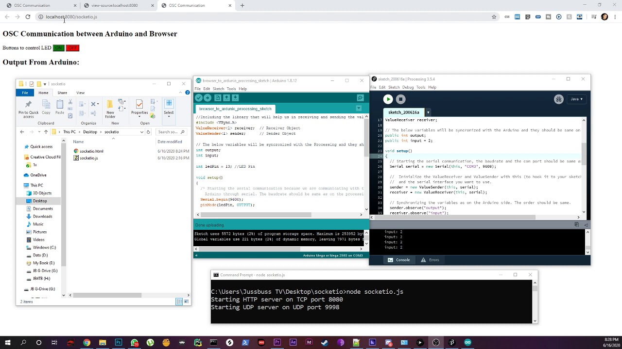 north stream
What directory is the HTML file in? What directory is the javascript file in?
lament epoch
@north stream they are in a folder socketio which sits on my desktop. inside the socketio folder is socketio.js and socketio.html and the script src in html header is just socketio.js as they both sit in the same folder and node is run on the js file in that folder
in my video above, the code for the javascript file should load when I click its link in view source, it does not, which suggests it not properly accessing that file, i have no clue why
north stream
Maybe open network debugging in your browser for a look at what is happening.
Also perhaps try accessing the js file directly from the URL bar (as I suggested)
 tawdry galleon
question, what happens first in for loops, iteration or condition checking
im using this bit of code
  for (int i = 0; i < 3; i++) {
    displayY[p1PaddleDraw[i]] = 1;
  }
to write ones into the positions specified by the values of an array, and im curious if how I have the for loop set up might have it run a final time with i=3
im also more just curious best practices for for loop conditionals, is it better to use i < 3 or i <= 2? Something else?
cedar mountain
This will stop at i = 2, after 3 iterations.
tawdry galleon
cool
cedar mountain
The choice of ending conditions is usually semantic: whether it's more important to emphasize the number of iterations, the ending value, or a sentinel that won't be hit, etc.
tawdry galleon
neat
thanks for the help!
actually i've got one more question
for arrays and variables that arent going to have values over 255 is it better to use an int or byte array, or does it not matter?
im curious about this because i was doing some math using sizeof on an array and while checking the arduino reference i discovered that because it was an int array i would need to do a bit extra math when i could just use byte arrays
cedar mountain
It depends... If the values are truly always supposed to be bytes, like pixels, it's a good idea to use that native type. If it's more of a "well I think the values will probably be small" situation, you might err on the side of not introducing a subtle bug if you happen to run across 300 one day.
Also depends on how RAM-starved the chip is and how much you can save given the array size.
 neat oxide
Im new to programing and robotics any newbie project ideas?
tawdry galleon
im not planning on using more than 255 rows or columns of leds so it should be fine to use byte
it shouldnt be ram starved at any point
 sturdy frost
what type of sensor would I need to make something like Edward Elric's Automail Blade? A distance sensor?
to detect my arm there to start the track moving
tawdry galleon
do you want the blade to move as your hand moves or just move on its own at a set speed when triggered?
tawdry galleon
do you want it to move when touched by your hand or something gets close to the sensor?
sturdy frost
When something gets close to the sensor
tawdry galleon
i would guess you need a proximity sensor, although i dont really know sensors that well
sturdy frost
Thanks! I'll find a way to program it, I just need the type of sensor I should use
would an IR sensor work too?
or an ultrasonic
but IR might be better
cedar mountain
Yep, there are a lot of decent short-range IR proximity sensors intended for "is the phone next to my face" use cases. Silicon Labs and AMS are two good vendors off the top of my head, and ST has some very nice time-of-flight sensors which give you precise distances, too.
sturdy frost
actually, Ed can just touch the automail
so a touch sensor might work
but thanks!
cedar mountain
Don't discount the simplicity of a button if touch is an option, heh heh.
sturdy frost
true
I can't find any good touch sensors that I can hide too
but can you paint them and they still work?
i could just hide it under the protective plating
If not, I'm sure it would work out
cedar mountain
The resistive touch sensors should still work if painted, I would guess, as long as it wasn't conductive silver paint or something.
sturdy frost
Ok
do you think this one would work? https://www.banggood.com/TTP223B-Digital-Touch-Sensor-Capacitive-Touch-Switch-Module-p-1158322.html?rmmds=search&cur_warehouse=CN

www.banggood.com
Online Shopping at Banggood.com!
It's the only one I can find that can fit almost flush
so he can touch it almost anywhere
maybe the hand with a slight delay
cedar mountain
I think that would be okay. With a quick glance at the data sheet, it looks like it does some auto-calibration, so paint on the electrode surface should be compensated for.
cedar mountain
(I'll let someone else offer an opinion there, as I'm more of an ARM processor guy myself, heh heh.)
proven mauve
Hey... if the USBMIDI and Wire libraries both have an .endTransmission(), could that cause them to get confused with each other?
cedar mountain
Not usually... many different libraries have a begin() function, for instance. The namespaces are library-specific.
cedar mountain
"When in doubt, print it out" is my debugging mantra. 😁
proven mauve
I can see where the issue is, but haven't found why lol
 graceful ingot
Hello everybody. Is this channel generally text chat or voice chat?
 odd fjord
text
graceful ingot
Great. I’m using an Itsy Bitsy M4 express to control some motors. There is a nasty audible frequency that the motors are making, I’m wondering if it’s the PWM frequency (~733Hz). Video link here https://youtu.be/GdPn_U5_Cfk

Audible tones being produced from Arduino PWM Moro’s controller
If it is related to the PWM frequency I was hoping I could get help changing the PWM frequency to something higher than ~20kHz
molten maple
are you using some sort of motor driver there?
is the print working?
maybe try: if(s == "12345678")
Open-source electronic prototyping platform enabling users to create interactive electronic objects.
what about the Serial.println(s); printout
your code already has it
do you get a printout of the RFID string?
ok so i think it should either be: if(s == "12345678")
or: if(s == "12345678\n")
if(s.toInt() == 12345678)
 bitter anvil
Hello
I was playing around with serial plotter. I wrote a code which sends the adc value of a2 on my arduino nano to serial port every 100ms
Out of curiosity I left the analog pin floating
And this is what I get from the plotter
I see a pattern here
What could that be?
I changed the delay to 10ms
And this is what I got then
And it don't even shows accurate values for my LDR
How can I solve this?
molten maple
when the card number prints out, are there any other strange characters that print out as well?
is it 01234567 or 12345678
k well maybe: if(s.toInt() == 1234567)
although i'm not sure if the zero will throw off the .toInt() function
it sounds like you aren't getting consistent readings from the RFID?
graceful ingot
are you using some sort of motor driver there?
@molten maple yeah there are some FETs there driving the motors
severe umbra
Hey guys im back on my project unsure how to fix it haha. Last few post we got something that is sorta working but not 100% what I wanted. Now what is to control a device's voltage with PWM. So that when pwm is on 255 it gets full 9v and when its on half it gets the 4.5v. So that we can slide it like that. Directly connecting it to pwm it didnt like it just made high pitch noise on the smaller pwm settings so that didnt work. Then I was told to try use a low pass filter which i couldnt get to work. So I got two questions what value capacitor should I use on 9v and pwm and if this schematic here is correct?
(Picture incoming)
The resistor in the picture is currently 1k
please do tag me if you answer this thanks!
sturdy frost
wait, is there any way I can make a touch sensor with aluminum tape and some wire?
severe umbra
ok so i changed schematic above so that + of capacitor is to base of transistor and the - is to ground and thats before resistor. Now im having some weird code problems:
int mediumPin = 6;
float value = 100;

void setup() {
  pinMode(mediumPin, OUTPUT);
}

void loop() {
  analogWrite(mediumPin,value);
}
This produces high pitch sound
int mediumPin = 6;
float value = 100;

void setup() {
  pinMode(mediumPin, OUTPUT);
}

void loop() {
  analogWrite(mediumPin,100);
}
this works
i tried both int and float to see if it was something weird like that
any idea why this is
 woven mica
If you are controlling a motor - you need some initial impulse to make it rotate first, then you can regulate the speed. With low voltage the torque is low, so the motor stops because of friction - and its coils make the sound on the frequency of the PWM.
severe umbra
im not 100% sure i undersand whataya mean lamfe but code wise if I do:
-> Analogwrite(pin,255);
-> Delay(10000);
->Analogwirte(pin,value);
would that work?
make it have a state
so if state 0 do the 255 and wait 10 secs and then after there do the value thing
woven mica
You can do it this way
woven mica
But the motor will still stop it you write send too low voltage to it - you should make sure you send only higher voltages than the one the motor stops at
sturdy frost
none of the touch sensors would work
can I just make one with aluminium taep?
tape*
sturdy frost
ah
severe umbra
also yes extrovert artist im pretty sure that question is pretty google-able haha
if you make a roll of tape between the two aluminum so that they dont touch
and do so that when you press the two aluminum touch then yh thats a touch sensor
you put ground on one plate and + on the other plate
but i dont think i need to say that since ya now directly touching the conductors
you shouldnt play with too high electricty
north stream
@bitter anvil That might be interference from ambient lighting, modulating the signal at the mains frequency.
@molten maple Note that an int on Arduino is 16 bits, and can only hold values up to 32767. You might want to try converting to unsigned long, or writing a string comparator that ignores leading zeroes, newlines, etc.
@sturdy frost If by "touch sensor", you mean "capacitive touch sensor", you can use anything even vaguely conductive (a banana will work). If you're trying to build a switch out of conductive materials, conductive tape would work, you'd need two contacts that would be bridged somehow: the usual lashup is to hook one to an input with a pullup resistor enabled, and the other to ground. Hooking one plate to + and one to ground would merely cause a short circuit, which is (very probably) not what you want.
sturdy frost
Thanks both of you!
severe umbra
also to my question i think i got it fixed i need the logic sorted out but im a programmer so that part should be ok
sturdy frost
that's good
severe umbra
i just saw madbodger answering stuff and i didnt wanna waste their time on something thats fixed hehe
north stream
For those of us following along at home, what was the fix?
severe umbra
the thing that lamfe suggested it needed to like rev up if you will haha basically i write a 255 real quick so you can see the difference to kinda rev the motor up
and then i write the value i want
int pin = 6;
int value = 0;
int state = 0;
int cooldown = 1000;
int revDelay = 30;
int fade = 5;
int startValue = 70;
int endValue = 230;
void setup() {
  pinMode(pin, OUTPUT);
  Serial.begin(9600);

  value = startValue;
}

void loop() {
  if(state == 0){
    analogWrite(pin,255);
    delay(cooldown);
    state = 1;
  }
  else if(state != 0){
    analogWrite(pin,255);
    delay(revDelay);

    if(state == 1){
      value = value + fade;
      if(value >= endValue){
        state = 2;
      }
    }

    else if(state == 2){
      value = value - fade;
      if(value <= startValue){
        state = 1;
      }
    }

    analogWrite(pin, value);
    delay(cooldown);
  }

  Serial.println(value);
}
is the code i am using as a kinda fade test
if i go lower than 30 revDelay It'll just make high pitch noise but 30 mms is so fast that theres not anyway you can feel or see a difference
and then i write the next value o:
the code i need to make now is something i done before but i cant remember the weird code i had to do haha
north stream
Nice work!
severe umbra
thanks!
oh i didnt know parseInt is a thing
that kinda makes this whole thing 100% easier
LOL
sturdy frost
how did you learn Arduino?
severe umbra
Me? Same way i learn anything. Pick up some books, see a few youtube video basically just taking all the information i can but thats given i been programming 4 years prior to learning arduino and lots of it is kinda the same logic
sturdy frost
ah, thanks!
 lavish rapids
Hello. I have trouble getting the tft library to work with my Arduino Due. Always get an error :/ Do you guys have any idea how to fix it? (I want to get my tft touch-shield to work with my Due. Displaying bmps works fine)
north stream
What is the error you get?
lavish rapids
@north stream it says:
C:\Program Files (x86)\Arduino\libraries\TFT\src/utility/Adafruit_ST7735.h:118:79: error: 'newColor' was not declared in this scope
uint16_t Color565(uint8_t r, uint8_t g, uint8_t b) { return newColor(r, g, b);}
 elder hare
can i use this (https://randomnerdtutorials.com/flash-upload-micropython-firmware-esp32-esp8266/) program to get micropython on my ESP32? i've only seen tutorials using cmd

This posts shows how to flash MicroPython firmware to ESP32/ESP8266 boards using the uPyCraft IDE software. It works on Windows, Linux, and Mac OS X.
north stream
@lavish rapids Hmm, I'm not familiar with newColor(), which appears to be the problem. Where did you find the code?
lavish rapids
It popped up as soon as i added "#include TFT.h"
north stream
Hmm, I'm guessing it either needs another include or another library.
odd fjord
@elder hare that certainly looks like what it is for -- I have not tried it....yet.
severe umbra
this is more math based than it is arduino based but I have my motor thing here and minium pwm i can set it to is 70 and maxium where it does a difference is 230.
So we have:
min = 70
max = 230
value = user input (1-100)
The user inputs a percentage where if they input 1% it returns 70. If they input 100% it returns 230.
The way to calculate this would be:
difference = max - min;
s1 = difference * (value / 100);
result = min + s1;
yup somethings wrong with this math
 nova comet
do the 0th and 1st IO pins on an ardunio behave the same as the others? those two pins are acting weird for me
i tested my code on two arduino's and i removed all of my circuit from it
and those pins are weird
north stream
Yes, those two are the serial data pins that communicate with the host: using them as GPIO pins can interfere in various ways.
severe umbra
i guess my code was wrong
it was some int to float stuff in c# that was being bad
haha
nova comet
rip
 random lily
Hello. Hi. I'm thinking of getting an Arduino. I've never worked with Arduino, but I've had a bit of Raspberry Pi experience. What kind of model would be suitable for me as the first Arduino?
 spark oar
I would suggest an Arduino Uno WiFi Rev2. It is a the basic Uno with additional wireless capabilities and is still easy to use with a breadboard.
 honest hollow
Hi, so I tested to compile my code with the FastLED library on a ubuntu system. I had to import the library manualy because the IDE said my library have to containe only non ASCI charaters (no space, number etc...). I changed the name but the error still here. So I moved the folder manualy to use it and when I compile my script, I have this error (Tetris.ino is my project) :
(This is the error (too long for discord 😭))
north stream
It looks like the library is using some compiler extensions (the __attribute__ stuff) that's having some sort of problem. I vaguely recall the header files do a bunch of #ifdef checks for various environments to configure all that, but if it doesn't match your environment, things may not be set up correctly. Alas, I don't know how to fix it
lavish rapids
Hey So I avoided the tft libary and used the ardafruit_gfx library. That does work fine with my Touch-Shield and the Arduino Due. Next step is the Touch-function. There for I used the TouchScreen.h Library from Adafruit. I connected the Touchports to the x- and y- axis. That works fine. But the coords it shows me are a bit strange (the screen is 320x240) and the cords start at x=220 y=161 and go to x=818 y=884. Do you have any idea why they are so high and dont start at 0?
woven mica
I think you need to calibrate it first
lavish rapids
do you have an idea where I do that?
woven mica
There should be an example sketch to do that
lavish rapids
mhh in the Library are only a frew files. 2 example scetches (there is no setting vor min/max), a "TouchScreen.h", a "TouchScreen.cpp" and a few others (like read me (it only describes what that library does in 2 sentences), coc, license)
lavish rapids
ok got it. I remapped the numbers with the "map" function 😄
 austere python
I am trying to get a photoresistor working. But it only reads 0. Any help?
When i remove the connection from the resistor to ground it goes to 1023
molten maple
what voltage do you measure at that voltage divided node?
and does the voltage change when covering the LDR?
possibly the resistor is not an ideal value
austere python
i dont have a multimeter, but the analogRead over serial does not change at all
north stream
I agree the resistor value is probably not ideal.
austere python
i have tried a 10k 470 and 220 resistors
could the wrong resistor value make it not change at all?
north stream
I thought it might be a 10Ω resistor, which would end to do that. 10k ought to work.
Note: the resistor isn't going to ground, as you have 3.3V hooked to the blue rail and 0V hooked to the red rail.
Nope, I got confused because I couldn't see behind the orange wire, scratch that.
austere python
im not sure what i did but it now seems to work but only gives 0 and 1023
north stream
D1 is a digital lead, not an analogue one, so that makes some sense.
austere python
given my board has only 1 analog pin is it possible to have multiple analog inputs?
north stream
Yes: you can use an external ADC, or add a multiplexor to your analog pin.
Or implement an ADC yourself, but that's the Hard Way.
austere python
It looks like my project might be impossible by the deadline but you were very helpful nevertheless. Sorry if some of my questions were a bit dumb
north stream
We all start out as beginners. And you're not the only one: there was one person whose project was due yesterday who got an extension to today. That said, there may be a way to accomplish what you're trying to do with the parts you have, but we'd need more details to make any suggestions.
 wanton shuttle
@austere python ESP8266 only has one Anolog in pin and that is A0, please move your yellow wire from D1 to A0 on the other side of the 8266, The pin is marked as A0. and then change your code accordingly.
odd fjord
@slow snow you posted it int #general-tech and #general-chat - please stick to one post
 grave garnet
Hey, I'm working on a DS input display. I have all the buttons working, I just need help getting the touchscreen working. It's a standard 4-pin touchscreen which I have access to all 4 pins. I've routed them to 4 analog pins on the Arduino pro micro. The problem I have is that the DS runs at ~1.8 volts while the Arduino pro micro runs at 5V. If I use standard code for reading the touchscreen, the DS freezes since I'm running a much higher voltage
 slow snow
?
 formal onyx
Hello, I'm looking for some help- I am making a robot with a lot of servos. I am using the arduino servo library. I have a function that I want to take in the ID of a servo as a parameter. Then this servo's ID is used in an if statement.
Basically I need to check if the servo's ID is a specific name. But I get the error when compiling. I tried comparing it to a string "servoFR" first, but that also didn't work. Any ideas?
north stream
@grave garnet Are you connecting to the touchscreen directly or to a controller? Is it a resistive touchscreen?
grave garnet
It's a 4 pin resistive touchscreen
this is basically what it is, I have routed each pin of the touchscreen to an analog pin
north stream
I'm unsure why it would matter then, if it's entirely separate form the other circuitry
north stream
@formal onyx Servo objects don't have an equality test, but you might be able to test their addresses.
grave garnet
by doing that, I'm putting a 5V signal into the DS, which freezes up the DSes 1.8v hardware
formal onyx
You mean test the pin I assigned them to?
I guess I could make a servo class that contains an ID for each servo that I could compare. Comparing to the pins doesnt really work because my goal is to use my function instead of Servo.write. Unless I'm misunderstanding what you mean by address which is totally possible
cedar mountain
I think @north stream was suggesting passing around pointers to the Servos instead, and comparing the pointer addresses.
formal onyx
Im not sure what that means
Im having a bad time coming to C from python..
I think I'd rather just make a servo class instead because I have other data to store about the servos (min and max pos, ID, etc), but im looking around online and it seems like people generally make a library instead?
cedar mountain
A pointer in C is kind of like the id() in Python, i.e. what is checked when you use a is b instead of a == b, though it tends to get used for more stuff. But if you have a reason to make a wrapper class anyway, that's a great solution.
Whether to put it in a library or not is just a code organization question.
north stream
@grave garnet So you're saying the touchscreen is connected to the DS as well as the Arduino?
grave garnet
Yeah
north stream
There's no way that's going to work then 😦
grave garnet
would it be possible to read the ds signals?
like wait for the DS to send out it's "high" voltage
and then read when it does that
would that be viable
north stream
The timing would be really tricky.
formal onyx
If I define a class, and create an object in that class, is that object's datatype its class?
Like if I am defining a function, and its argument is an object of that class, should I do
int function(classname object){}
?
Commented out is the code I am trying to replace with my class. (servoFR should be jointFR etc)
 lone ferry
You should really name the class Joint instead of joint so it's easier to tell apart from the variable named joint.
The constructor should also be named Joint(...), not servoJoint(...).
When you pass it to a function, it's best to write int commandJoint(Joint &joint, ...) otherwise is will make a copy of the joint object.
But really it would make most sense if you move that commandJoint function into the Joint class.
Oh, and you also need to put instance variables for ID, minPos, etc into the Joint class.
formal onyx
Youre right, it does make more sense to put the commandJoint function into the class. What exactly are instance variables? Truth be told this is my first time making a class in C.
lone ferry
@formal onyx When you write this->ID = ID; there needs to be an instance variable named ID in the class, which is what this->ID is referring to.
lone ferry
class Joint {
  char ID;
  int minPos;
  int maxPos;
  int pin;
  Servo servo;

public:
  Joint(char ID, int minPos, int maxPos, int pin) {
    this->ID = ID;
    this->minPos = minPos;
    this->maxPos = maxPos;
    this->pin = pin;

    servo.attach(pin);
  }
};
Something like that. 😄
formal onyx
Ohhhh I see, like how you have to declare variables before using them in the program. That's something that python has spoiled me with
lone ferry
Yes, exactly.
formal onyx
When i create a new object in the class, I want it to create a new Servo, with the name being the ID of the object, does your code accomplish this? I thought I would instead need to do something like this:
lone ferry
That code makes no sense, because this.ID is a char object, so you cannot also make it a Servo object.
formal onyx
So I should make another variable in the class that I can define when I create objects
lone ferry
Well, it depends a little on what you are trying to achieve here. I assume each Joint always has its own Servo? i.e. two Joints cannot use the same servo motor?
formal onyx
Yeah
I have a robot with 12 servos, each controlling a joint. Each joint has its own specific maximum and minimum positions (bound by the construction, not the servo's limits)
I am wrapping it in this class because I want to use my commandJoint function, which prevents it from being moved to a position that is outside the range of the joint (destroying it) and also flips 6 of the servo's movement
lone ferry
Right, so in that case the code I posted, where Servo servo; is an instance variable, is the right approach. Each Joint will now have its own Servo object.
formal onyx
There's no need to have
this->servo = servo; ?
Is this because each object has its own scope, so it doesnt matter that theyre all called 'servo'?
lone ferry
When you write Servo servo; it already creates one. Just like int minPos; already creates the variable minPos. But you do this->minPos = minPos; to overwrite it with the value you actually want. This is not needed for Servo, there you only have to do servo.attach(pin);.
And yes, they will all be called servo but that's OK because they are all in different Joint instances.
formal onyx
Ok, that makes sense, thank you.
formal onyx
Thank you a lot for your help, madbodger too, I really appreciate it. I'm sure I'll be back soon enough though, lol.
lone ferry
Haha, cool.
 sullen scroll
can arduino pico run led ring
 fringe ruin
Hi, I'm looking for project ideas on arduino which is useful and cheap. Can you advise me something?
lone ferry
For what purpose, @fringe ruin ?
north stream
@sullen scroll It should be able to, however there are many types of LED rings, it should be able to run most of them.
 gilded jay
guys, I have the same problem described in this issue:

GitHub
As title. this simple code works perfectly with lib version 1.0.7 if (!boschBME680.begin(0x76)) { Serial.println("Could not find a valid BME680 sensor, check wiring!"); while (1);...
any idea on how to solve or workaroud it? it seems that latest updates broke the lib
 gritty hound
Hey! My project consists in an Arduino which controls a LED strip alimented with 12V so I put the 12V alimentation on the + on my breadboard.
I also have a Bluetooth receiver and a SoftwareSerial to link it to the Arduino.
The problem is that now I use an other alimentation, a 12V one for the Arduino. (So, I use two alimentations, one for the Arduino and one for the LEDs).
So I'd like to link the VIN on the breadboard so both the Arduino and the strip use the alimentation.
I tried, but when I do that the Bluetooth Serial begins to bug, receive weird characters except the first one which is almost always correct... And when I use two alims, all works like a charm.
Is my Arduino undervolted? If so, any solutions to use one alim for both or should I use two?
Same alimentation for Arduino and LEDs?
I'm a noob
north stream
It's more likely electrical noise from the LEDs than a low voltage issue. You may be able to use some filter circuitry to isolate the LEDs from the other devices, to protect them from the noise or short duration voltage sags.
 hazy wadi
hi there dont supose anyone knows any good https on arduino resources on the internet on day three of googleing and have had a fix bag of results ?
cedar mountain
Possibly that would be specific to what you're using for your internet connection. Doing public-key cryptography on an 8-bit microcontroller is a bit of a pain, so the SSL would be likely to be handled by the chip handling the WiFi, etc.
formal onyx
Is there a way to concatenate multiple things together in a single expression?
This gives me an error, "invalid operands of types 'const char*' and 'const char [5]' to binary 'operator+'. But only when I have it doing multiple at once. If I just concatenate a string + this->ID, or a string + target, it compiles fine.
cedar mountain
I'm actually surprised that the single concatenations would work. Unless you're working with the more complex String types that can do dynamic reallocation, C++ wants you to be a bit more hands-on about where the memory is coming from to convert things to text, etc. The simplest solution would be to have separate Serial.print() calls for each piece.
formal onyx
Oh ok, that makes sense. I think maybe it compiles but C++ is not very happy about it, because im getting some odd results from serial monitor currently. I'll try your suggestion and see if it fixes it.
cedar mountain
Oh, I see why it was compiling... with a char* and an integer, it was doing pointer arithmetic. So "foobar" + 1 would evaluate to a pointer to the second letter in the string, and it would print oobar. But that wouldn't extend to more operands, and isn't what you want anyway.
formal onyx
Interesting
Well now I'm having a different issue.. somehow, instead of this->ID being "jointFL", it's 7. Which is the length of the string, but if I change the string it stays 7 so I think that's a coincidence
cedar mountain
So ID is declared as a char, which means it's a one-byte character value, not a string.
formal onyx
Oh, how do I declare a string?
cedar mountain
That would be a char array, like char ID[10] or however long you want it. With the wonders of C minutiae, the length needs to be 1 larger than the contents, to include the 0 terminator character.
Fair warning, you are about to get thrown into a lot of C hassles with strings, so if it is feasible, you might be happier using integer constants for your joint labels and just do something like #define JOINT_FL 3 to make them easier to read in the code.
formal onyx
What does #define do, exactly? Makes it so I can write JOINT_FL and it'll equate to 3?
cedar mountain
Yep, exactly. The #define is what's called a preprocessor directive, so it is essentially editing your code right before the compiler sees is to change all instances of JOINT_FL into the number 3. So the human sees the friendly label, the compiler just sees the number, and it doesn't use any memory for a separate variable.
 sturdy bobcat
Strings are complicated.
cedar mountain
Memory management, fundamentally. Languages like Python can create new strings at will and garbage-collect them when they are done with them, but C is intended to be low level and close to the hardware, so it wants you to understand where everything is in memory, who owns it, and when it gets freed, etc.
north stream
C is a pretty old, low level language, basically just a gloss on assembly language. Its string support is just "an array of characters".
formal onyx
Oh, ok. Yeah I guess coming from python I take strings for granted
cedar mountain
(And don't even get me started on Unicode...)
north stream
The advantage of C is it can use resources efficiently. The disadvantage is that you have to do everything manually.
formal onyx
And being efficient matters when youre on an arduino, I imagine
cedar mountain
Yeah. C on an 8-bit microcontroller can compete with Python on a gigahertz desktop CPU, which is really impressive when you think about it.
north stream
Heh, I was talking code with a friend over Discord, and it would convert emojis into :smile_cat: which looked the same but broke copy/paste.
We also found out that the Unicode escapes that worked on Linux bash didn't work on MacOS bash.
formal onyx
When using #define do I have to do anything special when I put in my label? because I replaced the original "string" (char) with my label, and now I'm getting a "expected primary expression before ( token" error.
safe shell
Maybe I'm abusing Arduino, but I do printf when I want to combine different data types and/or have things show up a certain way
formal onyx
cedar mountain
Can you show your #define? Possibly you have some extra punctuation in it, like a semicolon, which isn't needed.
formal onyx
Bingo, semicolon.
cedar mountain
This is one thing that people seem to love about Rust in comparison to C. The compiler goes out of its way to give you understandable and actionable error messages... "Hey, I expected blah here, but it looks like you have an extra brace up here, on this line, so I got confused."
lone ferry
The problem with routines such as printf or C++ std::string is that they need to be linked into your app, which eats up a lot of Flash memory.
But you can do this: char s[200]; sprintf(s, "Attempting to write %s to %d...", target, this.ID); Serial.println(s);
formal onyx
Well thank you guys a ton for your help. It took two days but I've managed to get a working class. Maybe my robopup will stand up today.
north stream
Here's hoping, that looks like a really nifty project.
formal onyx
Thanks
 errant geode
Hello. If I buy 2 the same oled displays, and both of them have the same i2c adress, can i use them? I know that is not possible with the same pins, but if i connect every device to other pin?
 exotic cove

" The only bad news about I2C is that each I2C device must have a unique address - and the addresses only range from 0 to 127 (aka 0 to 0x7F hex). One thing this means is that if you have two accelerometers (lets say) and they both have address 0x22 you cannot have both of them on the same I2C lines."
I'm having a problem using an array of bytes in combination with shiftout(), first time through the array, everything works as expected, but every time through loop thereafter, a number that isn't in the array is being shifted out and I can't figure out what's going on

Pastebin
cedar mountain
If your processor has multiple I2C buses, or supports a soft-I2C library, you can put those devices on different pins. Or there are I2C multiplexer chips which can be used, too.
exotic cove
if numberToDisplay is declared as an int of 1 and i use numberToDisplay *= 2 % 255 it also works as expected but this is just a test as i want to use an array ultimately
cedar mountain
The problem is the i++ % 7 line, which is incrementing i but not applying the modulus back to the variable. You want i = (i + 1) % 7 or similar.
exotic cove
ok, bad parentheses, understood, how is it changing the content of the array?
or is it just spitting out a number because the array index is out of bounds?
cedar mountain
Your i is ending up with values of 8, 9, 10, etc. so it's reading off the end of the array, yep.
exotic cove
ok, im a pythoner so i'm not used to getting a response besides an error for out of bounds array calls
hazy wadi
@cedar mountain i have found this its on my list to look into ferther https://www.arduino.cc/en/Reference/WiFi101SSLClient
Open-source electronic prototyping platform enabling users to create interactive electronic objects.
exotic cove
thanks very much
cedar mountain
No problem, welcome to the wonders of C, heh heh.
exotic cove
i've been arduino-ing for a long time but have been using far more clipcode than anything else. i do like it but it can be frustrating when it doesn't tell you when you did something wrong lol
perfect, the parentheses fixed it
cedar mountain
Yeah, it's an amazing language for shooting yourself in the foot... 😅 But I still like it.
exotic cove
also to anyone reading, that modulo should have been 8
cedar mountain
Good point, missed that.
exotic cove
good old off-by-one error
gilded jay
guys, I have the same problem described in this issue:
https://github.com/adafruit/Adafruit_BME680/issues/40
any idea on how to solve or workaroud it? it seems that latest updates broke the lib
GitHub
As title. this simple code works perfectly with lib version 1.0.7 if (!boschBME680.begin(0x76)) { Serial.println("Could not find a valid BME680 sensor, check wiring!"); while (1);...
 weak walrus
theoretically... if I have a TFT screen and only plug in the GND and 3.3v parts it should at least turn on right?
I am wondering if maybe my solder job is whack. i accidentally touched some of the tape on the connector
cedar mountain
There may be a separate backlight-control signal to get it to visibly turn on.
pine bramble
Hello everyone! I'm just trying to understand if a level shifter is needed when an arduino board has a 3.3 V pin. Does this mean it has a level shifter built in? I'm looking to complete this build:
https://www.instructables.com/id/ESP8266-With-Parallax-Serial-RFID-Reader-PN-28140/

Instructables
ESP8266 With Parallax Serial RFID Reader (PN 28140): This simple guide will allow you to interface a Parallax Serial RFID reader with an ESP8266 !
cedar mountain
Generally a 3.3V pin on an Arduino is a voltage supply available for powering other chips, but the Arduino pins will still be 5V I/O if the Arduino is otherwise powered from 5V, so you may indeed need a level-shifter for interfacing to some 3.3V devices.
pine bramble
Ah ok.
Its weird because iirc this card reader is a 5v device but the guide im following above wants you to use a level shifter.
north stream
The ESP8266 is a 3.3V device
pine bramble
ooh that would explain why im not reading anything
cedar mountain
Ah, sorry, my confusion about what you meant by "Arduino".
 pale shuttle
 light shuttle
Yup, the first one is generic and can be bought for $1-2 on ebay. Works great and even has extra serial pins
gritty hound
It's more likely electrical noise from the LEDs than a low voltage issue. You may be able to use some filter circuitry to isolate the LEDs from the other devices, to protect them from the noise or short duration voltage sags.
@north stream
I can't look at it know as I'm at my father's house but I'll look at it thanks
 visual ferry
anyone know why serial.println is reading and printing past the size of the char array im giving it?
unless I messed something up during allocation but, this looks correct to me
cedar mountain
C strings need a terminating 0 byte to indicate where they stop. The println routine doesn't overwise have access to the size of the array.
cedar mountain
No prob. Be sure to allocate room for that extra byte too.
visual ferry
yeah, got it :P
gilded jay
no one using BME680 lib here?
proven mauve
Anyone around familiar with datatypes for M0's in Arduino? Like a feather uses. It looks like ints and words are all 4 bytes instead of 2 bytes, but from what I can see everything else like longs, floats, bytes, chars, and bools all appear to be the same as the 8bit family?
I would do some testing, but im at work trying to revamp some code for when I get to my room, swapped from a 32u4 last night to an M0
and is there a difference between using ints and longs?
 mighty vigil
Yes. Integers (ints) are signed 16 bit numbers (basically +/- 2^15), whereas longs are signed 32 bit numbers (+/- 2^31).
proven mauve
I had some things saving to an external eeprom, and it used up the available space to the byte. But one of the items was an int. It looks like if I change that to an unsigned short I will be good to go with the same space usage...
@mighty vigil but it looks like with an M0 ints are 32 bit numbers also. It doesn't look like longs change though
mighty vigil
My bad, didn't see that you were on M0.
proven mauve
I think I finally see why people write code with stuff like uint16_t instead of int lol
 honest obsidian
Does anyone know how to use Serial.end() with SAMD21? end() function doesn't seem to stop Serial printing. Simple code below. Note: I am using the SerialUSB object on a SparkFun SAMD21 Mini/Dev Breakout Board.
`void setup()
{
SerialUSB.begin(115200);
while(!SerialUSB);
}
void loop()
{
SerialUSB.println("Hello World");
SerialUSB.println("Hello World");
SerialUSB.end()
}`
reef ravine
@honest obsidian what are you trying to do? is stopping SerialUSB necessary?
honest obsidian
I just want to stop my serial outputting without having to reupload code.
reef ravine
how about
`void setup()
{
SerialUSB.begin(115200);
while(!SerialUSB);
SerialUSB.println("Hello World");
SerialUSB.println("Hello World");
}
void loop()
{
}`
i think .end only resets the serial, so it keeps looping
or if you need it in loop put the print statements in a for loop and use a flag variable with if
honest obsidian
i think
.endonly resets the serial, so it keeps looping
@reef ravine It stops the print output altogether on the Arduino Uno. I think the difference with the SAMD21 is due the native USB port, so the end() function just doesn't work as is intended.
or if you need it in loop put the print statements in a
forloop and use a flag variable withif
@reef ravine I was trying to avoid this workaround, but after doing a bit of Google-ing, this appears to be my only solution. I appreciate you for chiming in.
 cold lagoon
i get this error message ever and ever again does anybody knew what it means ?
lone ferry
@cold lagoon That looks like your program is too large to fit in the Arduino's memory.
by 1056 bytes
cold lagoon
@lone ferry but it is just marlin
lone ferry
I don't know what that is.
cold lagoon
thats a 3d printer firmware. manny people have uploadet it to a board
lone ferry
Ah I see. But did they use a board with an atmega1284p? Or was it another processor?
cold lagoon
my board has an atmega128 (anet a6 board) i have seen manny tutorials how to upload marlin on to it
But thanks for the tip, I'm at least one step further 😄
lone ferry
Maybe you need to explicitly enable support for the atmega128?
cold lagoon
i belive it is because i enabeld an extra option in the code and now it is to big
maybe i dissable some other options i dont need
lone ferry
Yes, that sounds like the likely cause -- and the solution 🙂
cold lagoon
and i needet one week to find out :/
ok i disabeld sd support now it works THANK you
 north stream
hello, i made a variable called Score and i put this code so if a button is pressed and 2 other variables which are called randomNumber1 and randomNumber2 = the same value to add a point in score and i also put a thing to make the serial print write the score but when i open the serial print, it keeps on adding a point even if i don't press the button, can someone please help? thank you! sorry if my code is long
https://hatebin.com/zrvugghqfb
reef ravine
@north stream how is your button wired? it will always print score since the print is in the loop.
north stream
@reef ravine what do you mean?
reef ravine
Serial.println(Score); is executed every time it loops
north stream
but i put only add the score when randomNumber1 and randomNumber2 = the same value
reef ravine
then the print should happen only in that if block
north stream
so i did something wrong?
reef ravine
not "wrong" just need to change your code so it does what you want
north stream
how do i fix it?
reef ravine
if (button == true); { if (randomNumber1 == randomNumber2); { Score += 1; Serial.println(Score); }
then it only prints if button is true
and random 1 = random 2
north stream
that's what i have
reef ravine
not what you pasted
north stream
but i put the serial println in a different area
but ill put it in the same area anyway
still makes no difference after i fix it
reef ravine
is button always true?
reef ravine
is the print still up top in the loop?
reef ravine
ok, then the 2 numbers must be the same or it wouldn't print
reef ravine
it should only print IF button = true AND random 1 = random 2
north stream
can i call you if you have no problem?
north stream
yep
reef ravine
add Serial.println(randomNumber1); and Serial.println(randomNumber2); above if button
north stream
ok
cedar mountain
Note the semicolon after the if clause... The following code is always executed.
north stream
i did
reef ravine
good catch, if (button == true); { should be if (button == true) {
north stream
add
Serial.println(randomNumber1);andSerial.println(randomNumber2);above if button
@reef ravine i did it
reef ravine
and remove the extra ;
north stream
from where?
reef ravine
look up^^^
north stream
like this?
reef ravine
remove the ; after if (button == true)
reef ravine
now it should print when rand 1 = rand 2
north stream
now it should print when rand 1 = rand 2
@reef ravine its not
reef ravine
except you have an extra ; after the second if
reef ravine
ok, the button is from pin 3 to ground?
north stream
yes
reef ravine
make pinMode(button, INPUT); to pinMode(button, INPUT_PULLUP); and change if (button == true) to if (button == false)
north stream
I know I could’ve used a rib but I didn’t
make
pinMode(button, INPUT);topinMode(button, INPUT_PULLUP);and changeif (button == true)toif (button == false)
@reef ravine okay
i did it
still not working
reef ravine
so if the button is pressed AND rand1 = rand 2 it should print
north stream
so if the button is pressed AND rand1 = rand 2 it should print
@reef ravine should i do that?
reef ravine
does it do that?
north stream
in the serial print?
reef ravine
yes IF the button is pressed AND random1 = random2 THEN it should print
north stream
its not printing
reef ravine
please paste what you have now
north stream
in the serial print or my code?
reef ravine
the code that is running now
reef ravine
it won't paste like you did it before? or use pastebin.com
reef ravine
i see what's wrong, 1 sec
north stream
okay
reef ravine
int value = digitalRead(button); if (value == false) { if (randomNumber1 == randomNumber2) { Score += 1; Serial.println(randomNumber1); Serial.println(randomNumber2); Serial.println(Score); } }
north stream
do i need to change my code to that?
reef ravine
yes, button always equals 3 as it is written now
north stream
it already = 3
reef ravine
yes but we want to know the state of the button connected to pin 3
north stream
yes but we want to know the state of the button connected to pin 3
@reef ravine what's the state?
reef ravine
if (button == true) means if 3 = true
reef ravine
you need to digitalRead the button (pin 3)
reef ravine
then value will be true or false depending on if you've pushed the button
reef ravine
change the lines starting at 131 to the above code block
north stream
what do you mean?
reef ravine
in your link there are line #s on the left side
north stream
in your link there are line #s on the left side
@reef ravine yah
reef ravine
put int value = digitalRead(button); on line 130, change 131 to if (value == false) {
cedar mountain
We're happy to answer questions and help you debug problems, but you have to ask one first. 😉
 solar grotto
yep
thank you 🙂
im trying to make a very simple board game
with 8 leds in a line
when i press a button a random number between 1 and 6 gets chosen and the
turn on respectively
ive done that so far
and works fine
but what i want to do next is make it so if i get a random number again by pressing the button it adds up to the leds that were already turned on
theres other stuff too but thats the fist thing i want to do
cedar mountain
I don't quite follow. You want a random number, but you want the number to equal the number of previously-lit LEDs?
solar grotto
kind of like a dice
here
the first time you press it, the number you got (1-6), gets lit on the leds
so lets say i get 6 so 6 leds turn on
if i get 2
i win
if i get more than 2 the turn doesnt count
or if i get 1 then it adds up and ill have 7 leds turned on
cedar mountain
Oh, I see. The easiest way to do that would be to have a variable with the current number of LEDs lit, and each time the button is pressed, add the random number to it, and then light up that total number of LEDs.
solar grotto
so like using void?
i used it on the dice i have already but you mean to use it again?
cedar mountain
Like the butonator variable you have. You'd have like: ```int total;
total = total + butonator;``` and then use total to light up your LEDs in a loop like you do now.
solar grotto
ok ill try that
reef ravine
@cedar mountainToday at 2:55 PM
Note the semicolon after the if clause... The following code is always executed.
thanks for catching that and I learned something, i would have thought that would have thrown a syntax error
cedar mountain
Yeah, it probably should, or at least a warning... Not a good reason to ever do that on purpose.
solar grotto
hey it didnt work 😭
may i share my work with you?
maybe you could show me what you meant
im using tinkercad at the moment since i cant go buy an arduino
cedar mountain
Sure, you can use Pastebin or something to share code if it's too large to show here. What is it actually doing or not doing?
solar grotto
right now it doesnt add the numbers to turn on more leds
i tried a few other things too
the main code is on arduino uno (1)
 clear fog
Can anyone tell me if I can use digital pins on
arduino uno for hc-06 bluetooth tx and rx
using its RX and TX you need to disconnected everytime you reflash it
cedar mountain
You will need to use a software-serial library, but if you do, then any pins will work.
cedar mountain
Yep, you just tell the library which ones you want to use.
clear fog
so something like this? ```#include <SoftwareSerial.h>
SoftwareSerial mySerial(2, 3); // RX, TX```
Thanks @cedar mountain
solar grotto
hey edkeyes thanks for the help
i tried using another way tho cause it became a bit difficult and i think i made it ok
it works as intended at least
do you guys know how i2c works tho?
i think i want to make my game turn based with two players
solar grotto
ok
 sinful estuary
Hello, I have some code I found online for a NodeMCU that I found online, I wanted to know if it is possible to use the same code on an Arduino Uno with an ESP-01.
 rugged smelt
hey i have a problem with my rfid reader i use many different programs and libraries but still doesnt work, pins are conected properly and the lights on the rfid is on, but still its saying me its doesnt connect properly
 wraith current
@rugged smelt post a picture of your wiring
wraith current
if the rfid read is 3.3v logic then it might not work with 5v logic of the arduino.
rugged smelt
even if i connect it into 3.3V on arduino?
wraith current
yes. 3.3v for power is correct, but the logic signal of arduino is still 5v.
would be easier to get an esp8266/nodemcu type board to use with rfid because esp is all 3.3v logic.
but it might also just be wrong wiring.
@sinful estuary probably not.
rugged smelt
I'm quite new to this and I'm just learning, thanks for the help
rugged smelt
what
 icy mural
i need help with my program and circuit
rugged smelt
show
icy mural
i tried to make a self balancing object avoiding robot
the circuit is on fritzing
the problem is coming with ultrasonic sensor i believe
its not gining output
rugged smelt
sorry i cant help you with that im not at the same level of programing
rugged smelt
nope im at this server 1,5hour XD
icy mural
lol okok ty
elder hare
STRIPS[] = { &STRIP1, &STRIP2, &STRIP3 };
this will ALWAYS start with 0 right? is there anyway i can make it start at 1?
lone ferry
Index the array with STRIPS[i - 1] if i starts at 1.
Or if you don't mind wasting some memory, write STRIPS[] = { 0, &STRIP1, &STRIP2, &STRIP3 }; so that 0th element is there but isn't used for anything.
elder hare
@lone ferry how much does that extra 0 add in memory actualy? :S
lone ferry
@elder hare It looks like these are all pointers, so 2, 4 or 8 bytes depending on your platform.
elder hare
so nothing 😛
 undone bridge
Hey guys I'm new to electronics and Arduino and I am having some issues with a stepper motor and driver, hoping someone here can help me figure out what I'm doing wrong.
I have this (FL42STH47-1204A) stepper motor (1.2amp 1.8deg stepper motor) driven by a Polulo A4988 stepper driver.
I set the Vref voltage to 650mV according to the specifications (VREF=8⋅IMAX⋅RCS). The driver is also set to 16th micro stepping.
The issue I'm having is that when stepping the motor, it stalls really easily by even light friction by my fingers. There's no torque to the motor. But if i let the motor start spinning slightly first then I cant stall it no matter how hard i try to hold back.
Why is there no torque in the initial steps of the motor?
lone ferry
@elder hare Yes, the extra space is basically nothing. On Arduino it's just 2 bytes. But sometimes you run out of space and then you might need those 2 bytes. 😉
solar grotto
any tips for transforming bytes into text?
i wanted to use i2c for a turned based game but i went for software serial instead
tho i can only send characters not a string
but i want the other arduino to read it as "your turn"
and vice versa, the other arduino sends it two when he is finished
 tacit plaza
@solar grotto , couldn't you just have it listen for a specific character that isn't likely used anywhere else, and which could indicate "end of turn" to pass it over to the other? In the early days of serial computing, the same was accomplished by the inclusion of non-visible character values for things like "eof" (end of file), or by making use of the difference between a "return" (or new line), and "enter".
I am looking for advice, tutorials, links, code, or examples to figure out how to do the following:
I have two sketch files which work similarly, but giving different behavior. They both illuminate LEDs where the brightness dependent on the input values from an analog joystick.
What I would like to do, is to figure out a way to use a momentary pushbutton to alternate between the two different behaviors. Both sketch files leave plenty of room to combine the two with memory to spare.
Sketchfile1:
Illuminates LED1 as the joystick is pushed upward, LED2 as it is pushed to the right, 3 is downward, and 4 is left.
Sketchfile2:
All LEDs start at 50%, LEDs 1&3 dim when the joystick is pushed left, and brighten when pushed right. LEDs 2&4 do the same but with upward and downward joystick motion. (Imagine 0-100% from left to right, but the centering rests at 50%).
 bold ravine
Hi ,I'm trying to use the adafruit esp8266 Mqtt code on esp32 with necessary changes.
This is my code
https://pastebin.com/vsgzqNV2
I'm trying to connect to my hassio Mqtt broker with topic "test1".
Wifi gets connected ,then Mqtt gets connected but after that ,any new publishes to the topic are not detected .
Any help would be appreciated
wanton shuttle
@undone bridge The answer to that is the microstepping itself. Microstepping takes a full step of the motor and turns into a bunch of smaller steps by controlling the amount of current to the A & B phases of the motor during the stepping process. There are times when this current is very low. Low current = low torque.
undone bridge
@wanton shuttle hm.. right, is there any way to calculate the theoretical torque when micro stepping to 1/16 when the rated full step torque is 441mNm?
reef ravine
@tacit plaza Try setting a "flag variable" when the button is pressed. Put each behavior in a function. IF flag is low THEN function 1 ELSE function 2. Toggle the value of flag on each button press.
tacit plaza
I have found some examples for changing state which seem to apply, but to prevent bouncing they all use a delay, and no examples showing how to do so with any other inputs. So where should I put the delay, where it would not delay between joystick input changes?
wanton shuttle
@undone bridge I believe this formula is the one you would need...
reef ravine
see the "blink without delay" examples, by using millis and comparing times the code doesn't "block" while it sits there doing nothing during delay, this looks like what you need https://www.arduino.cc/en/tutorial/debounce
Open-source electronic prototyping platform enabling users to create interactive electronic objects.
wanton shuttle
undone bridge
@wanton shuttle Thank you, ill look into it 👍
Wow, 10ish percent at 1/16, no wonder i can stall it by breathing to hard on it 😛
tacit plaza
@reef ravine , so going by that example, I could then add my code in place of where it says, " // set the LED", and have one block encapsulated with:
if (mode == 1)
{ "act in this manner" }
if (mode == 2)
{ "Act this way instead" }
(initializing "mode" in setup, of course. )
reef ravine
that is the basic idea yes, i'm at work now so can't dive deep
tacit plaza
No sweat. That's been a great help. Thanks!
wanton shuttle
@undone bridge Your welcome.
 stable perch
hello guys, does anyone use the Kalman filter with the MPU6050 ???
 shy marten
@stable perch I don't, but if you're trying to decrease noise, I'd recommend using a moving average. I've used a n=50 moving average with an LIS3DH that worked quite well. Here's a study that uses the Kalman filter with the MPU6050 https://www.sciencedirect.com/science/article/pii/S1474667016336977 that might be helpful
pine bramble
Hello again, I'm having a bug with an RFID reader. Basically when I scan a card, it 'reads' it twice because of how the serial is saving or sending...? the card code. Is there a way I can clear the serial available return value?
cedar mountain
Just read it in a loop until there's nothing more available.
pine bramble
But thats what causes it to read the same value 'again'
and that opens the door twice
cedar mountain
No, I meant, if you want to clear the buffer, read it and throw away the values.
pine bramble
How would I do that? Is there a method I would use?
pine bramble
Ooh I didn't know cpp did that (coming from python xp)
 slow spade
formal onyx
slow spade
formal onyx
When driving servos with an arduino, but with external power, do you need to connect the ground of the servos to the ground of the arduino?
reef ravine
yes, without a common reference the control signal won't drive the servo
formal onyx
Because when I try and do that, the arduino shuts off and becomes unresponsive until I disconnect the grounds
 forest lark
Hi everyone, I just had a strange problem with 2 adafruit boards, I uploaded a test program to my grand central M4, changed something and when trying to upload it just says "uploading" forever.
I then tried uploading the same program to an itsy bitsy m4, it uploaded fine and then suddenly said usb device not recognised
I tried both boards on a different computer but am having the same problem. A second itsy bitsy works fine on that computer.
reef ravine
@formal onyx i'd suggest double checking your wiring, only the negative lead should be in common https://www.instructables.com/id/Arduino-How-to-Use-a-Servo-Motor-With-an-External-/
formal onyx
Could it be because I am driving the servos at 6.2v, not 5v? That shouldn't matter to the arduino, though, would it?
The arduino is being powered off USB, not the 6.2v
Huh, its working now. That's odd. I guess I wont complain
Must have been cosmic rays or something.
tacit plaza
Is there any short, easy, efficient way to convert serial input from ASCII value to text characters? I cannot seem to find any specific functions to do so, and trying to define each character based on value would consume too much memory.
north stream
It's the same thing, really. What are you really trying to do?
formal onyx
Is there a way to prevent servos from going to a random position when theyre first powered on? Each time I reupload to the arduino, even if the degree I'm writing stays the same, the servos jump to a seemingly random position before going to their written position
It's a big problem because theyre physically restrained to operate in about 70 degree areas, so while it is limited in software theyre going outside where theyre supposed to and its going to break if it keeps happening
north stream
That's two different things: power on and upload.
tacit plaza
@north stream , when sending through serial, the Arduino sees it as the ANSI numerical value. I would like to find out if there is some way to convert those values into more human-readable characters, instead of memorize ASCII values to know what letter a value represents.
Sorry, I meant ASCII not ANSI, that was a dyslexic typo.
north stream
Again, they're the same thing. If you receive it into a char type buffer, the print() routine will recognize that it's a character and print it. If you receive it into something else (like uint8_t or byte), the print() routine will interpret it as a number.
You could, of course, cast it: Serial.print((char) myvalue);
tacit plaza
Thanks. That's what I was looking for, I think.
Or rather, forgetting to cast to char before assigning the value to variables.
I guess by default, it gives the raw ASCII numerical value.
cedar mountain
It's really the same 8-bit value. It's just how print() decides to output it, depending on the variable type.
tacit plaza
It works now. Thanks!
 earnest zenith
Whats the cheapest board that does HID usb
for acting as a keyboard specifically.
it's not clear to me if the trinket does this
north stream
The Trinket M0 should be capable of it.
formal onyx
If anyone is curious (or has a similar issue in the future) I fixed my servos going to random positions at powerup by controlling the power with a relay, and writing my first positions to the servos BEFORE even powering them on. Then when theyre powered on they move right to where they should.
 lyric echo
Anyone know what this issue could be?
reef ravine
@lyric echo wiring or incorrect lcd initialization?
lyric echo
I made sure the wiring is correct, il send some code maybe i did somethign wrong.
#include <LiquidCrystal.h>
LiquidCrystal lcd(11, 10, A0, A1, A2, A3, A4);

void setup()
{
  pinMode(A5, OUTPUT);    //LCD display
  digitalWrite(A5, HIGH); //LCD display
  lcd.begin(16,2);        //LCD display
  Serial.begin(9600);
}
what is A5 for?
lyric echo
11 into RS, 10 into RW, A0 into E, A1 A2 A3 A4 into D4 D5 D6 D7
A5 is for A
I have a 1k OHM resister for A5 to A
reef ravine
do you have a link for your LCD?
reef ravine
set A0 - A4 with pinMode(Ax, OUTPUT);
in setup()
you can use analog pins as digital but you need to set them up first
 marsh cloak
can the Arduino Mega accurately measure time to the hundredth (possibly even thousandth?) of a second? I want to program essentially a stopwatch that triggers based on a sensor and displays the time (up to 9.999 seconds).
I'm still a bit of a novice at arduino, can the Arduino Mega do this? would it require any additional parts for accurate time-tracking?
reef ravine
@marsh cloak the millis() function measures 1/1000 (milli seconds), it should be doable
this might be a place to start https://create.arduino.cc/projecthub/AzureDragon/stopwatch-using-arduino-52b99e
🍕 time...
lyric echo
@reef ravine I tried it and its still the same
 broken depot
Is anyone using a SIM7600? If so, what carrier are you using?
marsh cloak
I made a circuit set in circuit.io for a flyball stopwatch. https://www.circuito.io/static/reply/index.html?solutionId=5ef295cfce5e950030ae5274&solutionPath=storage.circuito.io
Instead of the 3mm ir break beam sensor, I would like to use this : https://www.amazon.com/gp/product/B07G29YN56/ref=ox_sc_act_title_4?smid=A3UAIR0DYVQQPY&psc=1
And if possible, power the project with 8 AA batteries. Are there any possible problems or concerns with this? Should the power supply be sufficient? Will the larger sensors wire in about the same?
reef ravine
@marsh cloak Looks like you are on the right track. I'd suggest looking into an 11.1v LiPo battery for longer life (all those 7 segments will chew through AAs).
cedar mountain
I might be a little worried about the response time of the beam-break sensor. To avoid false positives from a falling leaf breaking the beam or something, they might have a low-pass filter on the output that would delay the response by some number of milliseconds.
marsh cloak
@cedar mountain The goal of the sensor is to detect dogs running through the gate to start the timer, and running back through it to end the timer, with probably an average total time of 4 seconds. So long as I don't need to measure times totaling below 1 second, should I still worry about that delay, or could the delay be worked around? More important than accurate timing is consistent timing across every use.
reef ravine
@marsh cloak since the sensors are designed for security they may have some built in delay to prevent false triggering, perhaps 100's of milliseconds.
cedar mountain
I didn't understand the use case... I thought you were timing baseballs or something needing more precision.
reef ravine
The example was a fly ball timer, @marsh cloak is timing dogs through a gate around an obstacle and back through the gate
marsh cloak
Sorry, making it for my sister who does dog agility training, she described it as being a "flyball dog racing" timer. i could have been more clear 😅
reef ravine
is 100ths good enough?
marsh cloak
1000ths is ideal, but so long as it can accurately do 100ths that should be good enough
reef ravine
then the concern is the one @cedar mountain mentioned, those sensors may have some built-in delay and it'll be hard to know what delay.
 exotic sphinx
Apologies for interrupting, but does anyone know where I can buy a Bluetooth module for my arduino, because I've had no luck with the current modules that I have purchased. I also need it to connect to my Samsung phone without the requirement of an app (such as "dsd tech" HM-10).
marsh cloak
shouldn't the delay be consistent? the timer doesn't need to be consistent with other timers, it merely needs to be consistent weith itself
reef ravine
may depend on temperature / humidity / dust...
hour to hour should be close
day to day maybe not so much
not that it can't be done, just you won't know the precision without some tests or better data than you are likely to get from the manufacturer.
 warped kettle
I am using esp32cam and arduino uno
When I want to upload code I got
Invalid conversion from 'const char*'
So I chang char ssid[] = ""
But in this time dosen't connect wifi and doesn't show my my http id
Could some one help me
forest lark
Hi everyone, I have a problem with my Grand central, I was busy uploading and modifying an Arduino sketch when the computer suddenly said "usb device not recognised". It did this before and I just pressed the reset button twice and it would work again. Now when I do that the neopixel stays red and the red "L" led continues to fade in and out. Any ideas?
stuck coral
Does it show up as a USB storage device @forest lark?
forest lark
Hi, no it does not
"Windows has stopped this device because it has reported problems. (Code 43)
A request for the USB device descriptor failed."
stuck coral
Okay, try another USB port on your computer, then try another cable, I have found the same issue can happen with iffy front panel USB
forest lark
I tried different working cables, ports and computers
stuck coral
Then while the red LED is on, I would try one more time to upload the blink example from arduino, this will probably not work but the next step is reflashing the bootloader if nothing else is connected to it.
Though if your red LED is going in and out, with a red neopixel, nothing should be wrong with the board, it should work
forest lark
running windows 10, no extra drivers installed
the sketch that is on it is still working
stuck coral
Well idk about any OS related issues, I dont touch windows with a 10 ft pole, but if it wont show up as mass storage it should be fine. USB is not being established between the computer and board
To any extent
forest lark
https://www.robotics.org.za/JLINK-OB-ARM?search=jlink will this work if its the bootloader?
JLINK OB ARM Emulator, Debugger and Programmer
stuck coral
In theory, but if you have a Pi already I find those + OpenOCD to be the better tool, most of those programmers I try are buggy
forest lark
Thanks, I only have arduinos and 2 other itsy bitsy boards
stuck coral
I still think its a USB port + cable issue, Im taking your word you tried a different computer with a different cable.
stuck coral
I mean, a Pi Zero W is $10, and you can do a lot more with it when you're done, sounds like it to me. Unless someone else here has another good troubleshooting step I think thats where you're at
forest lark
Thanks, I just uploaded the blink example to an itsy bitsy m4, but the grand central still does nothing
stuck coral
Darn, when did you buy the grand central?
forest lark
MIcro Robotics, its in South Africa
oh when, a month ago
on the 21st of last month to be exact
stuck coral
Hmm, I think you may have a board made last year if you're having a bootloader issue
Might be two years now that I think about it
forest lark
could be, there is 1119 printed on it next to the debug port. November 2019?
stuck coral
idk, maybe, I thought they fixed the bootloaders before that but it might have been December of 2019 not 18
forest lark
it is a beta edition
stuck coral
Idk, next time you get a M4 board in South Africa, before this happens try to update the bootloader to lock it
forest lark
ok, thanks for all your help, really appreciate it! Looks like I will be ordering a PI
stuck coral
Just double tap the reset button, when it shows up as a USB storage device just drag over the newest UF2 file for your board. And no problem, happy to help, sounds like a plan
forest lark
I just updated the itsy bitsys, there were both on v2.0.0, now 3.10.0
I bought them on the same order as the grand central
distant plinth
hey guys !
which kit is better for a starter
this is kit 1
this is kit 2
<@&617066238840930324>
north stream
Those links both return "Forbidden
You don't have permission to access this resource."
distant plinth
omg sorry my bad
1 X Button Switch with caps
1 X Remote Control
1 X 4 digital tube
1 X 88 Dot Matrix
1 X 1 digital tube
1 X Stepper Motor
1 X ULN2003 Driver
1 X 9g Servo
1 X IIC 1602 LCD Module
1 X Joystick Module
1 X Temperature Module
1 X Water Sensor
1 X RFID Module
1 X RFID Key Ring
1 X RFID Card
1 X Sound Module
1 X 1 Channel Relay Module
1 X Clock Module
1 X 44 Keypad Module
1 X RGB LED Module
1 X 9V Battery Clip
5 X 1K Resistor
5 X 10K Resistor
8 X 220R Resistor
this is the kit A
Package Included:
1 X Remote Control
1 X Electronic components box
1 X 830 Tie point breadboard
30 X Male to Male Jump wires
1 X 10P female to female jump wire
1 X 4-digit digital tube
1 X 1-digit digital tube
1 X 8*8 Metrix module
1 X ULN2003 drvier
1 X DIYmall uno r3
1 X Protoshield with breadboard
1 X 1602 LCD
1 X USB Cable
1 X 40P pin header
1 X Stepper motor
1 X 9g servo
1 X Active buzzer
1 X Passive buzzer
4 X Switch button
4 X Yellow switch button cap
1 X Battery box
5 X 5mm red led
5 X 5mm yellow led
5 X 5mm blue led
5 X 1K resistor
5 X 10K resistor
8 X 220R resistor
1 X Adjustable resistor
1 X HDX Tilt sensor
3 X Photoresistor
1 X Flame sensor
1 X Infrared reciever sensor
1 X LM35DZ temperature sensor
1 X 74HC595
1 X Plastic box
this is kit B
which one is the best for a starter
errant geode
Is there something like MCP3008, but smaller? I thinking about ATTINY85, but I need programator for it and if i will want to change code in future, i will have to unsolder it.
undone bridge
Hey guys, i'm new to arduino and programming in arduino language (C++?)
I have two stepper motors, each driven by a Polulo A4988 stepper driver, and i need to program both to move with a PS2 type joystick. I also need both motors to be driven simultaneously depending on the joystick direction.
Any tips/pointers would be helpful.
cedar mountain
@errant geode Are you looking for an ADC or a microcontroller? How many channels?
 spice nacelle
@distant plinth - either kit would be fine for a starter... there are enough bits and pieces in either kit to get you going... just choose the one which interests you the most... and in the long run you will acquire additional parts to feed any further interests you may have.
distant plinth
which parts come only with only one of them
i want to know them to see if i need them @spice nacelle
spice nacelle
I don't understand what you mean ...
errant geode
@cedar mountain I am looking for ADC, but smaller than MCP. I think that i can program attiny, so it reads data from 3 analog pins, and send it to main board by serial on 2 pins that left. (3ADC+2SERIAL+5V+GROUND+RESET=8)
distant plinth
@spice nacelle i meant : what are the bonus electrical components that i get with kit B
spice nacelle
You should do a venn diagram 🙂
spice nacelle

Using a Venn Diagram, students identify similarities and differences between two things by listing certain features in a chart containing overlapping circles. Venn Diagrams can be used to summarize, compare, or comprehend information.
Teach for Life is a global movement of pe...
distant plinth
ok i understand u
wanton shuttle
@undone bridge You get your motor torque issue figured out? lol.
@undone bridge this should help get you started
cedar mountain
@errant geode I mean, there are a ton of ADCs out there if you search Digi-Key, down to millimeter size. I'm not sure what other design constraints you have, though.
distant plinth
1 X Button Switch with caps
1 X Remote Control
1 X 4 digital tube
1 X 88 Dot Matrix
1 X 1 digital tube
1 X Stepper Motor
1 X ULN2003 Driver
1 X 9g Servo
1 X IIC 1602 LCD Module
1 X Joystick Module
1 X Temperature Module
1 X Water Sensor
1 X RFID Module
1 X RFID Key Ring
1 X RFID Card
1 X Sound Module
1 X 1 Channel Relay Module
1 X Clock Module
1 X 44 Keypad Module
1 X RGB LED Module
1 X 9V Battery Clip
5 X 1K Resistor
5 X 10K Resistor
8 X 220R Resistor
kit A
1 ADUNIO UNO R3 1
2 44 Matrix Keypad 1
3 5V Relay 1
4 Step Motor 1
5 Temperature Sensor LM35 1
6 Motor 1
7 IR Receviver 1
8 Vibration Sensor SW-520D 2
9 Jumper Cap 4
10 Key Switch(yellow) 5
11 DHT11 Module 1
12 Clock Module 1
13 Big Sound Module 1
14 Water Module 1
15 photoresistance 3
16 Active Buzzer 1
17 SN74HC595 1
18 LED sensor 3 Color 1
19 7 Segment 1
20 4 7 Segment 1
21 Passive Buzzer 1
22 B10K Variable 1
23 Flame 1
24 SG90 Servo 1
25 1602 Display 1
26 88 Matrix 1
27 830 Breadboard 1
28 Joystick 1
29 USB Cable 1
30 RFID Module 1
31 Remote Control 1
32 Blue LED 10
33 Green LED 10
34 Red LED 10
35 330R Resistance 10
36 220R Resistance 10
37 10K Resistance 10
38 1K Resistance 10
39 Jumper Wire 1
40 F-M Dupont Wire 1
41 9V Battery Cable 1
42 2.54mm 40Pin 1
43 Firm Packing 1
44 Resistance Card 1
45 module ultrason 1
46 CD d'apprentissage
kit C
which one is better
kit A is cheaper than Kit C
which kit is better for a starter ?
sorry about my annoying questions
north stream
They both come with an LCD and dot matrix, and keypad, which is nice. Kit C has an Arduino, breadboard, servo: a pretty good start. Kit A has a motor driver.
distant plinth
1 X DIYmall uno r3
1 X USB Cable
1 X 65pcs Cable
1 X 830 tie point breadboard
15 X LED
1 X Dupond Cable
1 X Potentiometer
1 X Active buzzer
1 X 74HC595
1 X Infrared Receiver
1 X LM35
1 X Flame sensor
1 X Ball Switch
1 X Photoresistance
kit A has these components as well
@north stream
which one has the best value
north stream
Just make up a spreadsheet, match like to like, and pick out what's important to you.
distant plinth
which things do u think that are essenitial and come only with one of these kits ?
undone bridge
@wanton shuttle haha yes I decided half step is plenty for my use. A little jittery on low speeds but I can fix that with some gears to be able to run at speeds where it's not an issue
distant plinth
@north stream
undone bridge
@undone bridge this should help get you started
@wanton shuttle thank you so much, I will look at it closer when I get home 👍
wanton shuttle
@undone bridge no problem👍
undone bridge
@wanton shuttle It worked! Just tweaked it a little, now i just need to add an acceleration/deceleration curve.
I looked at AccelStepper library but that one only supports acceleration/deceleration on predefined movements 🤔
 glad birch
hey all, my brain died, I just need to do url encoding and pulling a single letter field value(field is longer, the value is only one char, and I am using index of and substring to pull it arduino int fie//this for loop just makes this setup a little bit easier. cycles through all the url encoded fields. for(int i = 0; i <= 29; i++){ if(i<10){ //if it is less than 10 the total chars used is 3 int fieldIndex = header.indexOf("l"+i+"="); String diodeColor = header.subStringOf("l"+i+"="); //pull the value from the field for that LED led[i] = diodeColor; } else{ //greater than 10 the total chars used is 4 int fieldIndex = ((header.indexOf("l"+i+"="))+1); char diodeColor = header.subStringOf(fieldIndex,(fieldIndex+1)); led[i] = diodeColor; } } this is technically c++ because its a arduino program using a rest api with a esp32 and esp32's don't tend to handle raw json bodies well so I am using url encoding and that means i have l0=b,l1=r,l2=g etc for 30 leds and fixing color values to them so I made a for loop that will fix a value easier.... can't remember if int fieldIndex = ((header.indexOf("l"+i+"="))+1); char diodeColor = header.subStringOf(fieldIndex,(fieldIndex+1)); would using header.subStringOf(fieldIndex,(fieldIndex+1)) attempt to unsuccessfully make diodecolor(a char) into a string?
wanton shuttle
@undone bridge Awesome. Under File-Examples-Stepper, you will fine one called "stepper_speedControl. " That may help you to get an idea on how to speed control a stepper from an analog value.
 past nebula
Speaking of clock projects on Show and Tell today, any tips for handling DST with the RTC lib? I just reset the clock twice a year, but there must be a more elegant way... 😉
 sour tide
haha, @worthy thistle was just talking about this
past nebula
Yeah. Coding it from scratch is non-trivial. I thought about doing a halfway solution and adding a pushbutton switch that, when pressed and held for N seconds, would toggle between adding an hour to the displayed time or not.
tacit plaza
Just a quick question:
Can something like pins A2 and D2 be used in the same project?
cedar mountain
Yes, they're different.
 worthy thistle
Heh, yes, this DST issue has bugged me for the three years I’ve been using the Arduino based clock I built.
tacit plaza
That's what I was thinking, but wasn't sure. I was working on combining two different sketches into one, and between the two there would be two lines stating:
const int buttonPin = 2; // digital pin for Joystick button
const int joyX = 2; // Analog pin for Joystick X value
cedar mountain
The analog pin needs to be referred to as A2, which will be a header constant that evaluates to its real pin number.
(Although often libraries will try to detect that error and correct for it.)
tacit plaza
Does D2 need to be specified, or ok as long as analog pins are specified? Also, would it be good practice (in my case) to always use A to prefix analog pins, for purpose of saving code snips for future use?
cedar mountain
I'm not sure if there is a D2 constant, just 2 is typical. And yes, it's good practice to use the A prefix.