#help-with-arduino
1 messages · Page 59 of 1
 stuck coral
stuck coral
stuck coral
Would be a good test to see if its the servo or your encoder code
I see currentStateCLK where are you setting it's value?
 forest lark
hi, I am trying to communicate with a VESC motor controller and gps module with the grand central m4 using uart. On the Arduino Mega I used Serial1 for the vesc and Serial2 for the gps. I used Serial1.begin... on the Mega, but it doesnt seem to work for the GC. What would I need to change to get it working?
stuck coral
And I would if(counter>0){ counter-- } instead of setting it to zero in an if statment but thats just me. This works
 pine bramble
i forgot to do that ;:)
stuck coral
Happens
 north stream
@pine bramble You probably need to move your variable declarations outside your routine ```arduino
int counter = 0;
int currentStateCLK;
int previousStateCLK;
void loop() {
previousStateCLK = digitalRead(inputCLK);
if (currentStateCLK != previousStateCLK){
if (digitalRead(inputDT) != currentStateCLK) {
...
Wow
stuck coral
Wdym @north stream?
stuck coral
No you're not, but the variables you need to keep going through the loop are global in the code you gave me
pine bramble
He uh
Can u send code that reads the resistance from the potentiometer?
A0
Please
stuck coral
Hold on
analogRead() for the pot, but are you meaning to only set rotate's position from the encoder?
pine bramble
No no
I thought one of my pot was broken
but i think it still works
i need to test it
stuck coral
Ok, then you have the analog read code correct, as @north stream says I think its best practice to make your vars global but reading the code you should be OK
Since in each loop you do an analog read and set the value, or make it static just to prevent the allocation/deallocation
 bronze ember
I am trying to programm with the MKR Wifi 1010 but my mac can't detect it. What am I suppose to do?
bronze ember
I tried all the cable of my house and with one the mac detected it!!!!
stuck coral
What type is mod?
stuck coral
Ah, thats why. Cannot have a string object for an input to a switch statment
 mighty vigil
if it's a numerical string ("1","2",etc) you can use myString.toInt() to convert it
stuck coral
Because its a numerical comparison
stuck coral
Well what is stored in the string @lilac cedar ?
stuck coral
Will it always be a single character?
 lilac cedar
no
stuck coral
Ok, then yep, welcome to the land of if statments
lilac cedar
but I can make it
%99 I cant
Ok, then yep, welcome to the land of if statments
@stuck coral 😄
I solved it (I think)
I can used if and switch.case both
its like that : @stuck coral
if (mod == "goLeft"){
 mod = "1";
}

switch (mod.toInt) {
    case 1:
      //my function
      break;
}
I think I would make some delcarations at the top of your code for the commands
north stream
You could also use ```c
switch (mod[0]) {
case '1':
That is much clearner, depends on if you want to keep it as a string just reassigning mod feels weird to me but it works
north stream
Or if your choices are sufficiently regular (like "goLeft", "goRight", "goUp", "goDown": ```c
switch (mod[2]) {
case 'L': // left
case 'R': // right
thx for help , I have to use string bcs If data is not a String (sometimes I will send int data) it will be speed of car (My english is not very good , if I make gramatical mistakes , sorry for that)
 trim bane
@cedar mountain sorry for the delay, hope you remember my Qs (SRF01) i ran some code on the PICO using a HC-SR04 sensor and code worked no problem, powered the sensor without any issue.
 cedar mountain
Cool. So I'd tend to be suspicious of the single-wire UART, then, as that's a difference... possibly both sides are trying to drive the transmit at the same time?
trim bane
and thats the design of the PICO? which Microcontroller would you use? I tried the Gemma-M0 and it couldnt run it either
cedar mountain
Most microcontrollers should be suitable, but it'd be a matter of the correct software to mode-switch the pin as part of the serial protocol.
One thing you could try is to leave the data line disconnected and see whether things otherwise power up, to see whether the problem is isolated to that connection.
trim bane
yea, so ive powered just the power and ground and it powers on and then light stops where the flora and leo stay lit up after power on
just retried the Gemma-M0 and its the same as the pico, powers it and then drops straight away
oh and the Gemma couldnt initialise #include <SoftwareSerial.h> which was why i couldnt use it
cedar mountain
I'm not sure offhand what the light is telling you. Does the board stop responding on the console at that point?
trim bane
serial monitor shows nothing on the pico when powering the SRF01
cedar mountain
Just to double-check, you're powering it from a power pin, and not from like a GPIO, right?
trim bane
on PICO im powering from VCC and from Gemma the 3.3V
cedar mountain
By "serial monitor shows nothing", do you expect it to, or does the code simply print nothing to start with?
trim bane
I have a begin comment that i ASSumed would show
 robust spoke
@north stream you are amazing
@north stream thank you so much, that works!!
I'm new to Arduino I really appreciate it! I never even knew about static and what that means! Thank you again!
 woeful flicker
Does anyone know how to prevent servo motors from twitching to 0 when powering up even if their positions are not set to 0 in the setup?
mighty vigil
Reading a forum post on arduino.cc, it seems to be unavoidable. When you power on your microcontroller, there is a small amount of time before the servo starts receiving pulses, during which it is only being powered. Well, if the line is constantly low, then it obviously isn't in the 1-2 millisecond range. Thus, the servo is likely to behave oddly.
Someone suggested removing the bootloader in order to remove the delay, but I'm not sure how effective that would be.
 reef ravine
i would leave the bootloader alone except as a last resort
@woeful flicker what are you doing in setup?
woeful flicker
Hey there, its just an int for the servo position but I dont initialize to anything and the servos still spike to 0 during arduino power up. Its probably a circuit thing.
reef ravine
until the servo library "wakes up" the pulses going to the servos are undefined, if you set a value in setup perhaps it'll start up where you want it more quickly
woeful flicker
ok thank you for your help! I will look into that
north stream
@robust spoke The static keyword isn't strictly required. It just makes the variables not visible from outside the module, which can save a little memory if they aren't being shared with other code. I generally use it by default, as every little bit helps with these small-memory devices.
 mellow tusk
@trim bane make sure to set the baud of the serial at setup or no message will come across.
trim bane
yep have done that thanks @mellow tusk . its all working on my flora and leostick. just cant get it working on pico or Gemma-M0, goin to be time to pay someone i think. need to work out how much budget i have left
 wind drift
attachInterrupt(7, wakeUp, LOW);
This should be the correct setup for an interrupt, right?
stuck coral
digitalPinToInterrupt() Should do the trick @wind drift
The Arduino programming language Reference, organized into Functions, Variable and Constant, and Structure keywords.
With the end result being attachInterrupt(digitalPinToInterrupt(PIN_NUM), wakeUp, LOW);
wind drift
One weird thing still is that the serial monitor does not restart when it wakes up
But the rest of the code works
stuck coral
Depending on the chip, it shouldnt. If youre using something like a M0 or M4 the USB circuit gets powered down in sleep
wind drift
PLLCSR &= ~_BV(PLLE);   // turn off USB PLL
USBCON &= ~_BV(USBE);   // disable USB```

```delay(100);
USBDevice.attach(); // keep this
delay(100);
Serial.begin(9600);
delay(100);```I use these to turn off/on the USB
stuck coral
And it cannot sustain the enumeration as well
Yep
Just reopen the serial monitor when you need, not much else to do
wind drift
ah okay - not possible for it to resume in the current window?
wind drift
Okay not a big problem
One more issue I have is the LEDs on the pro micro are always(?) on (Green led)
Even if I set them to turn off
I think they turn on when the serial monitor is open
stuck coral
Which pins are the LEDs connected to?
 frail schooner
I think it's because if the rxtx communication
wind drift
int RXLED = 17; // The RX LED has a defined Arduino pin
int TXLED = 30; // The TX LED has a defined Arduino pin
frail schooner
Yeah I suppose it's gonna stay on because it displays that the Rx Tx communication is happening between arduino and your serial terminal
stuck coral
Yep, I wouldnt worry about it really. If youre trying to save power make a nice DEBUG constant to decide to print or not
wind drift
So right now I have my arduino pro micro, MPU-6050 & LED which is sometimes on.
When I put the arduino to sleep (LED off) - MPU is on to 'wake' it up when there is movement.
Inactive I have 6mA current
stuck coral
For sleeping that sounds like a lot
wind drift

Introduction Last article, I wrote about how to use our own homemade Arduino Pro Mini bare bones along with an OLED display and how to make both of them consume as little power as possible. In fact…
I even removed the LED & voltage regulator
But still at 5mA
stuck coral
What voltage are you running at?
You also do not appear to go into the ATMEGA32u4's sleep mode, 5mA is what its rated for in normal operation with pheripherals like USB disabled
wind drift
3v
Na when it's sleeping and I remove the MPU it drops to close 0mA
it seems the gyro + accelrometer uses about 4-5 mA when active
accelerometer alone less
but not sure how to disable the gyro
Gyro + Accel operating current: 3.8mA (full power, gyro at all rates, accel at 1kHz sample rate)
Accel low power mode operating currents: 10µA at 1Hz, 20µA at 5Hz, 70µA at 20Hz, 140µA at 40Hz
stuck coral
What do you mean by na? Your evidence is supporting what I said
wind drift
When I have only the atmega32u4 connected it's close to 0 mA
When the MPU is connected it's 5 mA
stuck coral
Ah, got it.
stuck coral
You need to write to that register over I2C
wind drift
Are there any examples that I could follow?
Tried to look it up on google but seems quite complex?
stuck coral
Well are you using a library for this chip?
stuck coral
Ah, well you see the step by step instructions, the register descriptions have a address to write to and which bits do what
Should be able to write to it somewhat simialrly to how you read from it, would look at the I2C description which will give you more info on how to use the write command
wind drift
I used this before to change the interrupt settings on the MPU
I assume I can do the same for this?
stuck coral
Yep
wind drift
Okay will give it a try in a few hours
 shut shale
hello i need help with arduino and get the value of a sms i receive from my phone to arduino
shut shale
sooo i have a gsm module and i can sent and receive sms
but i want to detect when i receive sms and get the value of the received sms
stuck coral
Ah, would be in the documentation of the GSM module you're using
shut shale
 #include <SoftwareSerial.h>

SoftwareSerial mySerial(10, 11);

String str;
void setup() {
  mySerial.begin(9600);
  Serial.begin(9600);
  delay(100);

}

void loop()
{
  if (Serial.available()>0)
   switch(Serial.read())  {
    case 's':
      SendMessage();
      break;
    case 'r':
      RecieveMessage();
      break;
  }

 if (mySerial.available()>0)
   Serial.write(mySerial.read());
   str = mySerial.Read();
}


 void SendMessage(){

  mySerial.println("AT+CMGF=1");    //Sets the GSM Module in Text Mode
  delay(1000);  // Delay of 1000 milli seconds or 1 second
  mySerial.println("AT+CMGS=\"+MyPhone\"\r"); // Replace x with mobile number
  delay(1000);
  mySerial.println("I am SMS from GSM Module");// The SMS text you want to send
  delay(100);
   mySerial.println((char)26);// ASCII code of CTRL+Z
  delay(1000);
}


 void RecieveMessage()
{
  mySerial.println("AT+CNMI=2,2,0,0,0"); // AT Command to receive a live SMS
  delay(1000);
 }

``` here is my codei cant find any way to do it
stuck coral
What GSM module are you using?
shut shale

Arduino Project Hub
How to connect A6 GSM GPRS module with Arduino and also work with “AT” commands. By EasyMades.
this one
arduino gsm gprs a6 sim900
stuck coral
Well after you send the AT command to receive a message, you need to listen for the reply
 while(mySerial.available()){
  // Read reply here
 }
You should probably make a receive function to handle all AT command returns
shut shale
but this will read all the message from the module right ?
stuck coral
You have a serial interface, it will return AT commands you need to handle, there is no filtering if a type of message..
stuck coral
Oh I see your recieve code, bit of a weird structure but Im sure youll manage. And cant you just scan for the +CMT to know which line is a received message?
+CIEV even has a count for you
stuck coral
I mean, I am sort of working on my own code atm and I'm sure you can do it. Make a function that receives the serial data and places it into a char array or string object, then write some code to find the command between the + and : characters then use the periods and quotation marks to parse the rest of the elements in the message.
lilac cedar
Anyone knows a good bluetooth controller app?
stuck coral
No, read() returns a single character, I would check out the Arduino serial examples to learn how to use serial
shut shale
then what?
stuck coral
You need to construct a char array or string object fromt the values returned from serial read. Stopping either because of a newline or serial.available() is false
lilac cedar
Anyone knows how to make a basic android app that sends any data to my bluetooth? (Just tell me which program and language I must use to make it )
shut shale
wait i have to make the string of the sms?
lilac cedar
They are program right?
shut shale
because read return 1 char each time ?
stuck coral
@lilac cedar they are a programming language to make an app... are you asking about a already made one?
And @shut shale yes
shut shale
if i use a list it will look like this?
stuck coral
A list?
stuck coral
Ah, well it would be ['a', 'b', 'c'] but basically yes. This is the correct way to store strings
Note that all char arrays will have a null char at the end to show where the end of the string is in the array, everyone new with C runs into that and it can make an issue if you dont account for it
shut shale
well if my array looks like this ['a', 'b', 'c'] how i can get the part i want from it?
stuck coral
By scanning over the characters, you are about to learn about writing parsers!
stuck coral
Or you can use a library like this https://github.com/botletics/AT-Command-Library but I 100% recommend you write your own parser.

GitHub
Library for Arduino IDE to send AT or ASCII commands via UART - botletics/AT-Command-Library
You will learn a lot about c
Although Im not sure how that library parses. Would 101% write your own
shut shale
btw
if i did the AT command to get a sms
is possible to do the AT command to send a sms ?
stuck coral
Yep, should be
shut shale
k thanks
shut shale
btw the library you give me is not helping me xd
sr but im new what this
why i cant write a string to Serial ?
stuck coral
What is the error you are returning?
shut shale
yes
stuck coral
Try str = '';
stuck coral
No, with a char array, and you cannot just set it like that
Char = single character, char[] = string of characters in an array
stuck coral
Yep, that will make a char array that is 12 chars long containing Hello World\0
shut shale
i can edit it with test += "test";
stuck coral
No, that will not work
shut shale
me python guy xd
stuck coral
I can tell
So in c, you dont have the garbage collection or memory allocation happening in the background for you, thats why python is a memory hog. In C you need to allocate a char array bigger then the string you want to parse, and use functions like strlcat or strlcpy to append, or interate over the array.
brb
pine bramble
Hello! i have some issues with my arduino nano board. I can't upload any file into it or even get the board info.
north stream
Does it show up as a USB device?
north stream
Ah, it shows up as a serial port, even better.
pine bramble
Is that bad bad or..
north stream
No, that's the opposite of what I meant by "better". That means it's recognized as a serial USB device, which it is. Have you set the board to Nano and port to COM1 in the Arduino IDE?
pine bramble
yes
north stream
What error do you get when you try to upload?
pine bramble
wait some so i can copy and paste it
oh and i also have the ATmega as an old bootloader
avrdude: stk500_recv(): programmer is not responding
basically that
north stream
That does sound like a bootloader not responding issue, so it could be an old bootloader running at a different speed, an issue with reset, a chip without a bootloader, or something interfering with the serial data (those pins are shared with GPIO pins 0 and 1).
pine bramble
how do i then reset the chip? I tried to hold the button for arround 10sec but nothing happened
stuck coral
You cannot just magically get the input, you need to write a parsing function for your moudles AT commands
It should take the string, and output a command and value(s)
Maybe if you're new to C and used to python check out the String object funtions, its not the right way but it will make your life easier
shut shale
im noob and bored 😢
and i cant get the value of the sms
this is the output if i dont use the var
this is the output if i use the var
@stuck coral why this is happening ?
 flat chasm
@mellow tusk thanks for your help with multi-file arduino code structure! Unfortunately I'm getting a lot of these errors In function MPU6050::dmpInitialize()': (.text+0x0): multiple definition of `MPU6050::dmpGetFIFOPacketSize()' /var/folders/s9/xwc0t5vd42j9br9l53kntxbh0000gn/T/arduino_build_608973/sketch/imu.cpp.o (symbol from plugin):(.text+0x0): first defined here
Here's my relevant code:
imu.h
#include "MPU6050_6Axis_MotionApps20.h"
imu.cpp
#include "imu.h"
robot.ino
#include "imu.h"
I'm using include guards too
stuck coral
@shut shale why are you printing one byte to serial then the next byte to the test vaiable in your loop?
Thats why it wont work
shut shale
im not printing im storing
stuck coral
this is the output if i use the var
@shut shale this example is printing one byte to serial, and the second byte to the variable
shut shale
oh really ?
stuck coral
When you run Serial.read() you get a char, so if you run it a second time in that loop you dont get the same char, but the next char
shut shale
oh
and how i can get it on both ?
 while (mySerial.available()>0){
   test = mySerial.read();
   Serial.write(test);

}```char test;
while(mySerial.available()>0){
test = mySerial.read();
Serial.println(test);
}
oh
stuck coral
Make more sense?
shut shale
yea
i will sent 1 -2 with sms
soo i can just read the last char
to do something with it
 proven mauve
@flat chasm do you have the same variables being initialized in multiple files?
or declared... whatever C calls it
proven mauve
did you do char test = 0; in your loop before the if statement?
stuck coral
Try a while statment instead of an if statment for reading serial @shut shale and did it work before with that delay?
And @proven mauve hes setting the value every serial read, he does not need an inital value, but it doesnt hurt
proven mauve
even without the declaration of char it'll work?
stuck coral
It wont compile if he doesnt... I dont understand what you mean @proven mauve
proven mauve
fair enough
shut shale
😢
stuck coral
i would learn C a little better, check out the serial examples in the IDE
And strings, comms in general
I cannot spend all afternoon writing the code for you, otherwise Id be busy on discord all day with everyone
proven mauve
i didn't see where he declared it, just the test = myserial.read().... I didn't think it wiuld know what kind of variable to make test doing that
stuck coral
@proven mauve idk how you can say that he hasnt posted his loop or globals
shut shale
 #include <SoftwareSerial.h>

SoftwareSerial mySerial(10, 11);


bool WaitForSMS = false;
char test;
void setup() {
  mySerial.begin(9600);
  Serial.begin(9600);
  delay(100);
  mySerial.println("AT+CNMI=2,2,0,0,0");
  delay(100);

}

void loop(){


  /*
  if (Serial.available()>0)
   switch(Serial.read())  {
    case 's':
      SendMessage();
      break;
    case 'r':
      RecieveMessage();
      break;
  }
  */

 while(mySerial.available()>0){
   test = mySerial.read();
   Serial.write(test);

   WaitForSMS = true;
  }
  if(WaitForSMS){
    Serial.println("");
    Serial.print("I received: ");
    Serial.println(test);
    WaitForSMS = false;
  }


}


 void SendMessage(){

  mySerial.println("AT+CMGF=1");    //Sets the GSM Module in Text Mode
  delay(1000);  // Delay of 1000 milli seconds or 1 second
  mySerial.println("AT+CMGS=\"+306980970615\"\r"); // Replace x with mobile number
  delay(1000);
  mySerial.println("I am SMS from GSM Module");// The SMS text you want to send
  delay(100);
   mySerial.println((char)26);// ASCII code of CTRL+Z
  delay(1000);
}

/*
 void RecieveMessage()
{
  mySerial.println("AT+CNMI=2,2,0,0,0"); // AT Command to receive a live SMS
  delay(1000);
 }
 */

 void updateSerial(){
  delay(500);
  while (Serial.available()) {
    mySerial.write(Serial.read());//Forward what Serial received to Software Serial Port
  }
  while(mySerial.available()){
    Serial.write(mySerial.read());//Forward what Software Serial received to Serial Port

  }
}
i want to send a sms with the value 1
or 2
proven mauve
thar she blows
shut shale
and i want to get the value and do something if is 1
like if i sent 1 i want to turn on a led
stuck coral
First you need to get the reply from the module into a char array, not a char, it is a AT command reply string, it will not just return a 1 or a 0
stuck coral
So would define a char rxBuffer[1048]; which I would populate with serial data until you get a newline or serial receive. And you need to write a parser
Look at the AT commands, the first section of the reply is the reply command
shut shale
i dont know how to write a parser
stuck coral
I know, you get to learn, it is very frustrating but rewarding and you'll learn a lot about c. No one is born knowing how to
shut shale
i want to finish my project but i dont have time to learn better C
stuck coral
Well if you dont want to learn C you'll have a hard time completing a C project
shut shale
my brain just cant work
i dont know how to use the array you told me to do
im done my brain hurt i cant do it anymore
north stream
Maybe just download the FONA library, it uses AT commands for SMS and might be compatible or at least a useful starting point.
wind drift
@stuck coral regarding my MPU-6050 low power issue.
I found this example where they mention the same parameters.
But why do they use D3, D5 ...
And why is D3 duplicated
before it would look like this #define INT_ENABLE 0x38
stuck coral
Just to give an idea on how you'd use the array, DO NOT USE, UNSAFE CODE @shut shale
memcpy(rxBuffer, 0x0, sizeof(rxBuffer)); // Zero out the buffer so you can get a end of line
index = 0; // Set the location you want to write to in the buffer
while(mySerial.available()){
  rxBuffer[index++] = mySerial.read(); // Read the char into the buffer, incrementing index when you do so
}
@wind drift just means the value at those constants definition is the same, looks like its defining the variable position in an array as a single bit, it is different because INT_ENABLE is a byte, the settings you want to change are bits
flat chasm
@proven mauve no I don't have the same variables being initialized in multiple files. here's a link to my repo https://github.com/Grace0/sbr
 wind drift
stuck coral
wind drift
stuck coral
This might help you @wind drift https://www.codeproject.com/Articles/2247/An-introduction-to-bitwise-operators
This article gives a brief overview of C style bitwise operators
wind drift
If I had to guess I would do the following:
#define MPU6050_SLEEP 0x6B
writeByte( MPU6050_ADDRESS, SLEEP, 0 )
That's the address for all of them
But if I always use the same address how does it know which one I want to change
Or does it also read the _CYCLE?
stuck coral
Its at the same bit position, in different bytes
wind drift
      #define MPU6050_SLEEP               0x6B
      #define MPU6050_TEMP_DIS            0x6B
      #define MPU6050_STBY_XG             0x6C
      #define MPU6050_STBY_YG             0x6C
      #define MPU6050_STBY_ZG             0x6C
      #define MPU6050_LP_WAKE_CTRL0       0x6C
      #define MPU6050_LP_WAKE_CTRL1       0x6C```

```    writeByte( MPU6050_ADDRESS, CYCLE, 1)
    writeByte( MPU6050_ADDRESS, SLEEP, 0)
    writeByte( MPU6050_ADDRESS, TEMP_DIS, 1)
    writeByte( MPU6050_ADDRESS, STBY_XG, 1)
    writeByte( MPU6050_ADDRESS, STBY_YG, 1)
    writeByte( MPU6050_ADDRESS, LP_WAKE_CTRL0, 0)
writeByte( MPU6050_ADDRESS, LP_WAKE_CTRL1, 0) ```Should be correct?
And why are there 2 LP_WAKE_CTRL?
stuck coral
Because the variable is two bits long
wind drift
Ah okay
stuck coral
That register is one byte long, two of the bits are used for LP_WAKE_CTRL
You need to use bitwise operators to set them after reading an inital value
wind drift
So my current setup is not correct?
stuck coral
No, writeByte( MPU6050_ADDRESS, LP_WAKE_CTRL0, 0) will set the contents of the entire 8 bit register to 0x0
wind drift
hm that's confusing 😄
stuck coral
Read that link i sent you and it will make more sense
wind drift
So I have to use &?
writeByte( MPU6050_ADDRESS, LP_WAKE_CTRL0 & LP_WAKE_CTRL1, 0)
Like this?
stuck coral
You will want to read the inital value, then XOR the bits you want to set/unset then write to the register
north stream
Not really XOR (unless you specifically want to toggle). To set bits, use "or", to clear bits, use "not" and "and".
However, LP_WAKE_CTRL_0 is a register address, not a bitfield: you probably don't want to do boolean logic on register addresses.
stuck coral
I usually toggle since you're reading it first but for this case yes. And isnt PWR_MAGMT_2 the register address @north stream ?
LP_WAKE_CTRL_0 is a bit along with LP_WAKE_CTRL_1 who are on one end of the PWR_MAGMT_2 register
north stream
I was thrown off by ```fix
#define MPU6050_LP_WAKE_CTRL0 0x6C
#define MPU6050_LP_WAKE_CTRL1 0x6C
Yeah, I'd probably do something like ```c
#define LP_WAKE_CTRL1 0x80
#define LP_WAKE_CTRL0 0x40
Where do I find the 0x80 and 0x40 in the datasheet?
north stream
Then either make #defines for the various combinations or just assemble the values manually like ```c
bits = read(PWR_MGMT_2);
bits |= (LP_WAKE_CTRL1 | LP_WAKE_CTRL0);
write(PWR_MGMT_2, bits);
Those come from the data sheet. See how LP_WAKE_CTRL are in the BIT7 and BIT6 columns?
stuck coral
0x80 = 10000000, while 0x40 = 01000000
north stream
That means the 7th and 6th bits from the right. So in binary, 1000 0000 for the 7th bit and 0100 0000 for the 6th bit.
stuck coral
Correct
north stream
Close: 0x01
lilac cedar
I have a int value but its negative , can I convert it to positive?
stuck coral
Yes, abs() will give you the absolute value of a number
lilac cedar
ty
stuck coral
Or ig you could multiply by -1 but that'll make a positive number negative
wind drift
#define PWR_MGMT_2          0x6C

#define CYCLE               0x20
#define SLEEP               0x40
#define TEMP_DIS            0x08
#define STBY_XG             0x04
#define STBY_YG             0x02
#define STBY_ZG             0x01
#define LP_WAKE_CTRL0       0x40
#define LP_WAKE_CTRL1 0x80```writeByte( PWR_MGMT_1, CYCLE, 1);
stuck coral
I think TEMP_DIS is meant to be 0x04. And you need to do what madbodger suggested https://discordapp.com/channels/327254708534116352/537365760008257569/715652601781157943
Read, set bits, write
You are not writing the CYCLE bit, you want to write the entire existing register with the CYCLE bit now enabled
otherwise the entire register is just set to 0x20, setting all tyhe other bits to 0
mellow tusk
@flat chasm multiple defines means you’re reading in the .h file multiple times. By using guards I’m guessing that you’re using #ifndef #define #endif on all your .h file definitions. If that is the case comment out each #include at a time and see which one clears things up.
 cyan jasper
Hey, Do you guys know any open source arduino type (maybe faster with native USB, eyeing on pro mini) data acquisition software? If there aren't many or the ones out there is not much useful I'd like to start a new project.
(if it has been done well, i don't want to reinvent the wheel)
stuck coral
Well the IDE has a thing for graphing live over time, for storing I normally make a c or python application that reads serial and saves to a format like CSV, although there is probably someone here with a great suggestion
Once you get the data in a standard format like CSV you then can use many tools for making graphs or doing whatever you need with the data
Could just use screen to make a serial log file, output CSV from the arduino serial, and cut off any header data you put in, that would be another option
cyan jasper
What i was thinking is there a all in one thing that does it but thanks for the input, if i decide to do it at least it gave me starting point 🙂
 lofty wave
Is it normal for arduino to crash often?
stuck coral
No, means you have a memory issue
If its actually crashing, or it may be stuck in a loop forever
lofty wave
I have a LIDAR hooked up to the arduino and in the loop, arduino receives distance and signal strength. I then convert distance to a frequency and play it with tone(). Could it be that arduino can't handle changing tone so fast?
I just thought of it now, actually - why I haven't tested going at a lower rate.
stuck coral
Well I doubt its crashing because of reading something too fast, then the values would be nonesense not a crash
lofty wave
sometimes it does something weird actually
stuck coral
No, output a bad measurment, acting weird means you have a memory issue
lofty wave
above is normal behaviour
that has happened a few times but it's not the most common way to "crash"
stuck coral
Well does it output bad data to serial, or actually crash?
lofty wave
Not sure what you mean with actually crash but ye, it's outputting gibberish there
stuck coral
Can I see your code?
lofty wave
Sometimes it just stops completely
sure
I've adapted an already existing code, I'm used to python, very little experience with arduino, so the parts done by me may cause some emotional pain.
stuck coral
Can you copy and paste using the formatting in discord?
lofty wave
it's this right?
stuck coral
Yes
lofty wave
it's too large
stuck coral
Oh boy, wanna pastebin it to me?
lofty wave
does it retain format?
yes it does. i tried on another site and it didn't retain formatting

Don't mind the incredibly horrible way to store information. It was mostly for testing and even that wasn't working properly, which may or may not have to do with the fact that I'm using indices above the length of the arrays... xD
Again, very new to arduino. Also, the frequency still needs adjusting, should be lower overall, and still not sure on the shape of the curve.
stuck coral
Might take me a sec to get back to you, a bit busy with somethin, Im willing to bet your "horrible way to store information" might have something to do with it
lofty wave
No worries. Just glad to get some help, since it's gating an otherwise very fun activity.
stuck coral
First off, I have no idea how you are using analog read since youre not configuring the input 😆
lofty wave
I mean, it works. @_@ I did find it weird, though. I had to configure the digital read but for analog it was working without.
stuck coral
It shouldnt, I dont think it is frock. And buttons are digital, not analog, would be much better to use digitalRead for the button
Add some pinMode(); statments
cyan jasper
I have a LIDAR hooked up to the arduino and in the loop, arduino receives distance and signal strength. I then convert distance to a frequency and play it with tone(). Could it be that arduino can't handle changing tone so fast?
IIRC tone is blocking function it does not continue until it finishes or interrupt triggers
lofty wave
it isn't
because i didn't set a time limit
tone can be set "forever" and a new tone() will update it
or notone()
IoTPanic is helping me out right now over pm and it's probably just that i forgot to initialize stuff properly AND the way i'm storing information
cyan jasper
uhm just a remark you can use Serial.flush() for hardware serial. It puts CPU on hold until serial data finishes
lofty wave
hmm where would that be useful?
cyan jasper
another remark i think software serial not capable of doing 115200 baud
lofty wave
alright but that's what's in the manual for the tfmini LIDAR
cyan jasper
another remark i think software serial not capable of doing 115200 baud
but not sure about that either
been a while since i used that
lofty wave
the worst part is i knew the problem was there, but since it was still printing out numbers for some reason, i kept it as a feature so i could later figure out why it kept printing numbers
smh
 hexed agate
Can anyone tell me what gfxglyph dX, dY are for?
I read dY are pixel offset in cell from baseline, what is the baseline? y Advance ?
reef ravine
@hexed agate does this help? https://learn.adafruit.com/creating-custom-symbol-font-for-adafruit-gfx-library/understanding-the-font-specification

Adafruit Learning System
Learn how to create a custom set of symbols to be easily displayed with the Adafruit GFX text features.
hexed agate
It does not
Ah, there seems to be some required reading, https://learn.adafruit.com/adafruit-gfx-graphics-library/using-fonts

which explains some stuff referenced but not explained in the guide.
reef ravine
I'm fairly new myself but I find "it's all there" - but often requires some digging to find "there"
hexed agate
nah still confused.. the font stuff is barely documented at all
"As you can see the dX value varies between 2-4." say what now?
"The dY value is the distance from the baseline of the character to the top of the glyph. " But nothing says what the baseline is..
reef ravine
I believe that the baseline (using the graphic above) is 15 and the whole "cell" is 0-23, 0-15, dX and dY shift your pattern inside the cell
hexed agate
I think the baseline is the Yadvance , and the yoffset is in reference to that so it is always -19 or so for non descending chars,, and xoffset is relative to the chars xadvance, which is usually fixed width, so it lets you center it
  //Index,  W, H,xAdv,dX, dY
  {     0, 16,21, 21, 3,-19}, // 32,00 test square
I will give that a try and see if the math adds up
reef ravine
I don't have the hardware to check, if you run the example code and play with values does it become clearer what does what?
 tawdry galleon
quick question, if I make an int array will all the values default to zero?
just int displayX[16];
stuck coral
If it is global, it is likely to be initalized as 0, but if you need everything to be zero use memset() which will set your array to a known value
ie memset(array, 0x0, sizeof(array));
But great question! C arrays do not have an inital value
tawdry galleon
cool, thanks!
mellow tusk
@tawdry galleon not only do arrays in C / C++ not have initial values neither do any other variables. When a variable is declared memory is allocated for the type of variable. The allocation process does not zero out that memory space. So you are given whatever crap was in memory at that location at that time. As a rule whenever a variable is declared immediately set it to 0 or -1. If you are using classes then during the constructor function is when you should initialize you’re variables.
tawdry galleon
Cool, I just declared them at the top of the sketch and used the memset command to set them to 0 in set up
I’m using it for the x and y values on a led grid that need to be powered or set to ground
One other quick question, why is the word clock highlighted orange
cedar mountain
What IDE are you using? Possibly it's flagging an undeclared variable.
stuck coral
I decided to say array instead of any variable since I know structures can have inital values and honestly I really need to like dig into how C handles that to get a better understanding
Some C gods will tear me to shreds wrong here and there 😜
tawdry galleon
@cedar mountain sorry I didn’t clarify, using the arduino ide and it was in a variable declaration
cedar mountain
Ugh. Apparently each library is allowed to provide a list of words it wants to highlight, for whatever reason, and they turn orange whenever you use them, even if it's not in the library's context. So you can ignore that, it seems...
tawdry galleon
Good to know, thanks!
 zealous nacelle
hi i was wondering if it would be possible to make a gpr system with arduino
stuck coral
Do you have a microwave module for that purpose?
zealous nacelle
no but would a radar sensor module work?
stuck coral
I have no idea, I have never done anything with radar and nothing involving ground penetrating radar. Looking it up I think a rough version might be doable as a hobbyist project but I would think you will need something much more powerful for signal processing than an arduino. And I am not sure, you need something thats 1-2Ghz but Idk about the power you'd need or any other details
I would need to know the sensor details to tell you if it would work with a micro
Im sure someone here has a better idea then me, I just wanted to ask, I will be following up on this tomorrow to see what others have.
zealous nacelle
What im trying to do is see if i have a sinkhole under my yard. im normally good at finding sinkholes what i mean by that is a few months back i opened a sinkhole and almost fell in at school XD
stuck coral
Huh, As long as it doesnt need to be high res sounds like it can be done
zealous nacelle
thank you this has been very helpful if i do fallow thru with the project i will make sure a post pictures.
stuck coral
Alright, I would get more opionons from others here, and/or in the embedded engineering disocrd that was promoted in the #general-tech a few days ago
zealous nacelle
thank u so much
stuck coral
Np
 tidal sonnet
Can I use wire.begin() to change the I2C pins on an Arduino?
Or does it depend on which 2 pins on the Arduino board are made for I2C, hardware wise?
 safe halo
I currently have pin 12/13 mapped on my esp32 for my UART but anytime i try to upload my new sketch the program cant access the debug port. Yet when I disconnect the attached UART it works fine.. any idea why?
I'm declaring them separately.
HardwareSerial Serial_Debug(0);
HardwareSerial Serial_Main(1);
I have problem with my gsm module
When i try to send a sms i get the ok but i dont get the sms on my phone
This happened after some tries i did
Before this the sms works but now no
safe halo
@tidal sonnet I believe you define the pins according to which ones on the arduino can do I2C then call the wire.begin()
 stable perch
Hello!! Can this type of screen (Kindle screen) be connected to the Arduino ??
reef ravine
@stable perch that might be tough on an Uno, this may give you ideas, https://hackaday.io/project/168193-epdiy-976-e-paper-controller
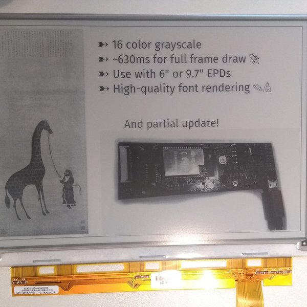
EPDiy is a driver board which talks to affordable E-Paper (or E-Ink) screens, which are usually sold as replacement screens for E-Book readers. Why are they interesting?
- Easy on the eyes and paper-like aesthetics
- No power consumption when not updating
- Sunlight-readabl...
wind drift
mh if I want to power my arduino from a coin cell
do I need to add some kind of boost converter?
 boreal jackal
depends on which kind of arduino, but probably yes
reef ravine
don't forget a converter will always draw some current...
wind drift
ah yeah true
Other question. I want an LED to light up every second or so and turn off again.
Would it make sense to put the arduino to sleep every second too then?
to save battery
cedar mountain
Watch out for the current rating of a coin cell. They tend to be used for low-current applications, so may not function well for 10s of milliamps.
And yes, putting the Arduino to sleep can save power, so if you're battery constrained, you should do it as much as you can. In fact you can probably have the Arduino sleep even with the LED on if you want, and only wake the processor up when you run code and change state.
wind drift
Ah I will try that
Another question:
is it possible to only have the arduino wake up when there are 2 interrupts present?
And capacitor question:
Is it possible to have a capacitor light up an LED for let's say 10 seconds?
cedar mountain
There are some processors that have some special pin-logic stuff which might be able to handle combining interrupts like that, but generally you'd wake the processor on either of the interrupts, have it quickly check for the other condition, and then go back to sleep if it's not activated.
Depending on how much current the LED take, you'd need a relatively large capacitor, into the supercapacitor territory, but it can be done.
 teal vine
@cedar mountain hey, I am new to Arduino and was wondering how to get Arduino in sleep mode
cedar mountain
@teal vine I'm afraid I'm not an expert on Arduino libraries for that, which might vary depending on MCU, since the sleep and wake capabilities can be processor-dependent.
wind drift
Well at the moment it uses 15 mA when idle (LED off) - which seems too much for my liking.
My idea was that I could maybe get rid of the arduino part.
Attach my MPU-6050 gyro with an interrupt somehow to the big capacitor to turn on the led for 10 secs.
teal vine
@cedar mountain ok thanks will check it out
pine bramble
Hello! I have a stupid question :S. I'm a begginer in this world, could someone explain me the differences between an Arduino board and Adafruit board? Is it only the brand? Are there any hardware differences?
cedar mountain
AFAIK you'll need some sort of microcontroller to configure the IMU on power-up, at least, since it doesn't have any sort of internal flash settings.
But you don't really need a capacitor for that, as you'll also need a battery anyway, which could power the LED.
wind drift
@cedar mountain yeah but the 15 mA idle for the microcontroller seems quite high 😦
cedar mountain
@pine bramble Not a stupid question. Arduino is an ecosystem of hardware and software, with official boards and libraries but also a large number of clones and third-party extensions. Many boards made by Adafruit run some of that software, and Adafruit also contributes their own libraries back into the ecosystem.
@wind drift Yep, there's a lot of opportunity to optimize that if you want. Underclocking the CPU, sleep mode, etc. You could even arrange to have the MCU configure the sensor and then literally turn itself off.
pine bramble
@cedar mountain Thank you :D. I have some other questions about a project I would like to do, but I don't want to bore you hahaha
cedar mountain
That's what we're here for. 😁 Depending on the project, there's a number of #help-with-<foo> channels that might be appropriate.
pine bramble
That's really nice, I think I'm going to use this server quite a lot during next weeks 🙂
wind drift
@cedar mountain Do you think I could use a transistor to 'simulate' a two-interrupt?
As an example
I want my circuit to turn on when it is dark & there was some movement detected
So I could use a photoresistor on the transistor
and once the MPU detects motion it triggers the transistor to let electricity through
that way the arduino would always stay off when it is bright
cedar mountain
That can be done, yep. My personal bias would be to just use the motion interrupt and have the MCU read the light sensor before reacting to it rather than trying to do all the logic in transistors, but different people judge the complexity of hardware versus software differently.
wind drift
Yep but in the case where the MCU reads the light sensor it uses more energy, compared to the transistor, no?
especially if I have constant movement during daytime
cedar mountain
Yeah, if you're in a constant-movement scenario, gating that signal makes more sense.
wind drift
Oh maybe a photo transistor is even better in this case?
pine bramble
Which kind of board do you recommend for block-programming in MakeCode Maker editor? Arduino or Adafruit? Is it irrelevant in this case?
cedar mountain
I'm unfortunately not that familiar with MakeCode, but we do have a #help-with-makecode channel.
pine bramble
Thanks! @cedar mountain
tawdry galleon
Is it possible to run short snippets of code before set up is called
Like a if statement that sets a variable based on a little bit of math?
north stream
You can do things like initializers: ```c
static int myvar = (NPINS > 13) ? (NPINS / 2) : (FIXEDPINS + 3);
cool, cool
thanks!
 exotic sphinx
isn't makecode the coding for Microbit?
north stream
Microbit can be programmed with several systems, including MicroPython and Arduino.
 dark tide
And MakeCode can be used to program several MCU's, including Circuit Playground Express
 weary ridge
I'm doing a modified signal backpack (gonna be permanent on bike and maybe also on helmet) and just discovered that I ordered the wrong battery holder (AAA instead of AA). Beyond duration, is there anything else I should keep an eye out for if I use the AAA holder?
north stream
Less current capability?
weary ridge
Alright. I think I'm gonna order the right size holder and steal the jst connectors from these ones (since no one seems to have stock of the jst connectors in canada).
tawdry galleon
2 quick questions (well, maybe not quite quick)
1 why does the uno r3 have a the atmega16u2mur for interacting the usb instead of just a usb to serial converter
2 if i connect a micro usb port to a usb to serial converter to the rx and tx pins on a arduino bootloaded atmega328p can i use the upload feature of arduino ide to program the 328p?
 rain crown
Hey all - hoping for some guidance and perhaps some expertise in working with a pressure transducer. What I'm looking for a very sensitive air pressure transducer that I can interface with the Arduino. Looking for something with high accuracy between 0-2 psi. Doesn't need to be any higher than that, but does need to have great resolution between that 0-2. Plan to convert the output to cm H2O - 2psi = ~140cm H20. Never need more than that -but I need good reliability and sensitivity between that 0-2 psi. Most of the pressure transducers I'm finding are much much higher than this. It would need to have resolution to the hundredths place (e.g. output of 1.12psi - and ideally an error range of no more than 0.02psi). Anyone with insight as to where to even go for something like this? Thank you!
north stream
@tawdry galleon The FTDI was replaced by the 8U2 (later the 16U2) not only because it's cheaper, but because it can implement different interfaces, not just serial.
And yes, you can program an Arduino with an external serial interface, you don't have to use the built-in one.
 potent heart
@rain crown this is a mild vacuum. Are you after a vacuum pressure sensor?
rain crown
@potent heart no - I'm measuring exhaled pressures - which are typically measured in Cmh20 . - and rarely exceed 140.... so it's very low pressure when compared to PSI. (see conversion of PSI to cmh20: https://www.convertunits.com/from/psi/to/cmH2O ) -
Do a quick conversion: 1 pounds/square inch = 70.306957829636 centimeters of water using the online calculator for metric conversions.
potent heart
STP (normal room conditions) are around 14 PSI
rain crown
That's good information - so I'd probably need something that would compensate for that above STP
Any thoughts then on a pressure sensor that could provide that type of resolution?
above the STP
potent heart
So you need a pressure meter with good precision which covers the range around normal atmospheric pressure.

We stock a few barometric pressure sensors, great for altitude and weather measurements. This pressure sensor is special because it comes with a metal port! Unlike other pressure sensors, ...
rain crown
some of the pressures would be negative - in that there are both inhaled measurements (which would be relatively negative) and exhaled measurements (which would be relatively positive)
potent heart
I've never tried this one, but it has a metal port, and claims a 24 bit ADC.
Negative compared to 14, yes.
rain crown
@potent heart you are awesome! Thank you so much!!
tawdry galleon
good to know, thanks!
one other follow up question, is the 16u2 and its extra protocols actually leveraged in the uno r3?
@north stream
cedar mountain
@rain crown Honeywell also has an extensive line of I2C pressure sensors with differential or gauge inputs, so you can have one side open to the atmosphere and measure the pressure relative to that with high accuracy.
rain crown
@cedar mountain that's great to know - is there a site where one can look at sensors from Honeywell? (Sorry if that's a newb question, but this is a bit all new to me)
exotic sphinx
That's pretty cool that a sensor so small can measure up to 25 psi for only about $15
rain crown
no doubt, @exotic sphinx -I ordered one just now - but I'm intrigued by @cedar mountain mention of the honeywell sensors, too
reef ravine
I think you'll be pleasantly surprised by the accuracy of MEMS pressure sensors, I have one that tells me if I've moved it up or down by only 2 or 3 feet, not much change in air pressure there...
exotic sphinx
If you don't mind me asking, what is this going to be used for?
reef ravine
i'm building an aircraft "6 pack" for some buddy's who fly RC airplanes
exotic sphinx
Sounds advance
reef ravine
one step at a time, get the IMU working, add altimeter, add compass, etc
exotic sphinx
One step at a time is always the best way to go, good luck!
reef ravine
ty
cedar mountain
@rain crown Here's the product pages: https://sensing.honeywell.com/sensors/amplified-board-mount-pressure-sensors
Honeywell amplified board mount pressure sensors
They're generally carried by the usual distributors (Digi-Key, Mouser) too. A little on the expensive side, though, versus cellphone-class sensors.
rain crown
Thank you, @cedar mountain ! This is fantastic!
@cedar mountain Most difficult part now is to find out which would be the best for my application. This is all new to me - learning all this is a bit overwhelming for sure as far as trying to find the right sensor. The cost is not prohibitive, but as you said, it's significant where I would want to make sure I choose the right one as best I can. It's a proof of concept build initially
@rain crown Honeywell also has an extensive line of I2C pressure sensors with differential or gauge inputs, so you can have one side open to the atmosphere and measure the pressure relative to that with high accuracy.
@cedar mountain this is exactly what I would need -
reef ravine
my 2 cents, get one that is differential, that way it'll be less sensitive to random changes in air pressure, i.e. how much are they exhaling or inhaling compared to whatever the barometer reads that day
cedar mountain
The RSC is the deluxe line, with 24-bit resolution. The HSC is a decent compromise, with fewer bits but still plenty for most applications, and an easier I2C interface.
The datasheets have a nice part-numbering diagram that lays out all of the different pressure ranges and package options. However, you may need to make some compromises depending on what is in stock at distributors... in many cases you can find the same effective sensor, but it's labeled with a range in psi instead of a range in pascals, etc.
reef ravine
I just wish I had the time to build half the cool ideas I get from this channel!
@cedar mountain Speaking of bits of resolution, while "more is better", doesn't anything more than 12 or 16 bit seem a little overkill for an arduino project? Or have you made something that needed those extra bits?
just curious, I looked it up just now and NASA never needs more than 15 digits of pi to navigate the solar system, even then they are off by inches over billions of miles (not that digits and bits are equivalent, but relatively)
rain crown
@cedar mountain It appears that the RSC, from what I'm seeing, don't have a sensor that can exceed 20 in H2O - which is about 50 cm water.... given that I need to be able to read pressures of about -140 cm h2o to +140 cm h20 - it seems that the RSC series may be TOO senstive for the application I need? Am I reading that correct?
reef ravine
H2O or Hg?
rain crown
H20
It appears that perhaps this may suffice, though 15PSI is well beyond what is needed..... https://sensing.honeywell.com/HSCDAND015PDSA3-amplified-board-mount-pressure-sensors - it's also the only one I can find that is both differential and can do both + and -
reef ravine
take a look at "Applications" listed on that page, seems to it the bill...
rain crown
I noticed that as well, @reef ravine ! - the negative measurement ability is key for sure - needs to be able to assess that
reef ravine
looks like 140 cm/H2O is about 2 psi
take a look at https://sensing.honeywell.com/sensors/amplified-board-mount-pressure-sensors/trustability-rsc-series
The TruStability™ RSC Series is a piezoresistive silicon pressure sensor offering a digital output for reading pressure over the specified full scale pressure span and temperature range
+/- 2 might be too close for your application, +/-5 will handle anyone (i guess) but at the cost of only using half the resolution of the sensor
if nobody exhales or inhales more than +/- 140 then 2 psi is perfect
rain crown
The issues with those, @reef ravine is that they are +/- 2 and +/- 5 in in h20 - which is very low - if it was PSI it would be perfect. The issue is that +/- 5 in h20 is +/- 12 cm h20 -
unless I'm reading that wrong- it's not PSI - that's the resoltuon
reef ravine
think i confused the HSC and RSC pages, you are right, sorry
https://sensing.honeywell.com/RSCMJJM005NDSE3-amplified-board-mount-pressure-sensors wouldn't quite do it...
rain crown
I did the same thing at first - for a second I thought that was perfect - but I think https://sensing.honeywell.com/HSCDAND015PDSA3-amplified-board-mount-pressure-sensors is the closest to what would work - I really like the sensitivity of the RSC, but it's a bit TOO senstiive I think, in that it can't go high/low enough and would block out at those higher pressures
cedar mountain
@reef ravine With barometric pressure sensors, 24 bit is very handy for detecting small altitude changes. But not usually needed for other applications, yeah.
reef ravine
@cedar mountain thanks! (i'll have to check my baro code)
@rain crown the HSC above is +/-15 psi, you only need a little over 2 psi as I understand this so you'll be using only a fraction of device's resolution
rain crown
correct, @reef ravine - I wish they had one that was like 0-5 PSI - but I don't see that it exists
they either have one that is very low (too low) for what I need, or the +/- 15 PSI - I don't see anything in between
It's a bit of a "dead zone", so to speak
cedar mountain
They should. You might have to look on the mbar or kPa scale for equivalent values.
rain crown
KpA to cmH20 is roughtly a 10x difference - 5 in KpA is about 50 in cm h20
I don't even see anything that talks about kpa- - seems it's all in h20 , PSI, or mbar
the ones I see that are like 0-5psi don't have a negative capability - that's the problem with those
there's only a handful (literally) that seem to be able to do negative pressure values - and the one I linked is the only one that seems to fall within the range that I need - unless someone else sees otherwise
reef ravine
i found one at Mouser that'll do it - for $500 😦
reef ravine
depending on budget, perhaps it pays to get the HSC (still not a cheap sensor though) and see if it'll do the job
rain crown
yah - I think that's what I will do - see if the HSC can get accurate results as well as consistent/repeatable results. If I do have to go to a more expensive sensor, then I may have to petition for a grant 😉
can you link the $500 sensor ? curious what the specs are
reef ravine
this is a proof of concept device?
rain crown
yes
rain crown
yah - the negative part is the difficult issue - measuring inhalation pressure (which is a negative #) - in addition to exhalation pressure (positive)
rain crown
The first one you linked looks really good! The second one only goes to 7in h20- so not a big enough range
reef ravine
140mm = 5.5 inches, no?
rain crown
cm, not mm 😉
reef ravine
oh boy it's been a long day, sorry!
rain crown
HA! all good! yah - this one looks pretty solid: https://www.mouser.com/ProductDetail/Amphenol-All-Sensors/DLV-005D-E1BD-C-NI3F?qs=%2Fha2pyFaduhK2LllMcluHuRWmMMmEulGrp2Fz0IzwCI4ok4FQglvFKYEYaRwoUC3
reef ravine
a tube to the subject, one to free air, get the measurement of the difference, voila
rain crown
Think that one is better than this one? https://www.mouser.com/ProductDetail/785-HSCDAND015PDSA3
reef ravine
the Amphenol is closer in range, more resolution, is I2C, and is a bit cheaper...
but now you are in the ballpark
rain crown
so it sounds like the amphenol would be the better choice
reef ravine
at least for proof of concept i think so
rain crown
thank you!
reef ravine
you are welcome, the key to this was scrolling allllll the way down on the pressure parameter search on Mouser
cedar mountain
Looks like Amphenol acquired All Sensors a couple of years ago, and that's part of their product line. Haven't used them personally, but talked to them at trade shows before, and they seem to know what they're doing.
reef ravine
good info never found on a datasheet 🙂
rain crown
that's awesome - just ordered from Mouser! Will keep you updated! Thank you @reef ravine and @cedar mountain
reef ravine
good luck!
rain crown
thank you 🙂 - excited to start playing around with this - I'm sure I'll have more questions - and really appreciate all the help
stable perch
My idea is to make a device similar to the Kindle but for me to put some questionnaires and he send the answers via Bluetooth or WIFI.
Is there any device that I can do this ??
with Arduino ??
 visual ferry
anyone know of a proper way to break up source files compiled w/ the arduino IDE
so like, I'm writing a OLED OSD for my project and I want to use multiple source files for easier management
visual ferry
i mean ig the arduino IDE will concat any ino files in a project folder together but idk that doesnt seem like the greatest way to do things
maybe I could consider working with the compiler binary directly (using a Teensy 4.1)
or uhh, avr-gcc ig
idek tbh i cant seem to find much on the subject
 woven mica
@visual ferry you usually create a .h and .c file and write it like a library, but put it in the same folder like the .ino file.
visual ferry
ohh, that works?
oh right no swearing, woops
i mean i feel like it'd do the same concat stuff i was talking about earlier, but, ig i can try it
woven mica
You then #include the .h file in the .ino file
 dreamy nebula
Is there an Arduino with the same pin-outs and footprint as pro/pro mini but with more memory?
 solid stag
is there away to see how many steps a stepper motors has done using code?
cedar mountain
That'd just depend on the stepper library. It could easily keep track if it wanted, since it's generating the steps. Some of them would want to keep a net step count as a position indicator, though might not keep a total distance-traveled count.
cedar mountain
It looks like there is a Stepper.step_number variable which tracks the current position, but there's no total-distance count.
solid stag
k well thanks ill try firguing that out
stuck coral
Compiler error?
wind drift
 #define CONFIG           0x1A

^```yep
     p_reg->CONFIG = config;

^~~~~~```And it seems the library wire.h can't be used?
stuck coral
Did you mean p_reg->config = CONFIG;?
CONFIG is a prefefined integer, not a part of the struct you are pointing to
stuck coral
Yeah, you cannot point to a structure field like that
p_reg is a struct you have a pointer to if you are using ->
Also, I bet CONFIG is defined elsewhere
Which is why you have the unqalified-id error
stuck coral
Are you sure no files you improted into your sketch define it? Any of the .h files?
And please address your misuse of structures first
wind drift
Hm I just used the same code on my arduino pro micro where it works fine
stuck coral
Does nrf_spim.h define CONFIG?
Which is a nrf board specific file
The micro would not have included it
stuck coral
Which one of them is including nrf_spim.h or Arduino is because you selected the nRF board, try naming CONFIG in your sketch to something else like DEVICE_CONFIG or something
Idk what your CONFIG is for but name it appropriatly
wind drift
it's for programming the MPU
stuck coral
PROG_CONFIG then?
stuck coral
So you sure you're supposed to #define it?
Should be a struct field
According to the way you're using it
Not an int
tawdry galleon
I don't know if this goes in here or project help, but I'm wondering if there's a way to do something like how the circuit python express appears as a usb device that you can drop files into with an atmega328p and then interacting with that file through Arduino code
so if i made a config file that I could drop in on my computer, then the Arduino code would parse the file and change it's behavior
so i guess this boils done to a couple questions
can Arduino code parse files, is there seom soft/firmware or a seperate ic that would let me do this, and would there be a better microcontroller for the job
stuck coral
Well the UF2 bootloader thats on M0 and M4 chips is able to show up as a filesystem and read the file placed within it to overwrite what's in flash, though I am not sure if the file ever makes it to persistant storage in theory if you got the USB file system going it would be trival to do what you need with it. So it is certainly possible
Would have to make sure to change the SERCOME acting as the serial output
wind drift
https://codeshare.io/Gk8VvO
This code is programming my MPU to trigger when there is movement.
This code is working. I have an LED set up and when I tap my table it triggers.
https://codeshare.io/alnPBB
This code is programming my MPU to trigger when there is movement & ONLY enable the accelerometer to save energy. (Gyro is off)
This code is not really working. When I upload the code the LED is on all the time.
The only thing that really changes is the #define part at the beginning and the writeByte in the void setup
the problem is happening on my nRF52840 feather express. On my arduino pro micro both work
solid stag
so im tryning to make a simple x and y machine for maybe laser printing or somthing and i was wondering if i would just use dc motors as i have alot more of than steppers
wind drift
Okay nevermind found my problem.
I had to put writeByte( MPU6050_ADDRESS, 0x37, 160 ); // now INT pin is active lowat the bottom
 unreal monolith
I need a sanity check if you don't mind. I'm running some tests on a STM32F405 Feather board using Arduino. I wanted to check the ADC and I'm getting much higher values than I would expect. When grounded I get ~0 but when connected to 3.3V I'm getting ~1101210. This scales well when I connect a 10k pot. I'm running:
#define LED_CHAIN_PIN A0 // Resistor string from LEDs
int ledV = 0
...
  // Read LED Chain
  ledV = analogRead(LED_CHAIN_PIN);
  Serial.print("A0 Voltage is: ");
  Serial.println(ledV, 3);
I thought the default was 10-bit but with the STM32 you could set it to 12-bit but a value of 1101210 doesn't make sense so I must be missing something
 safe shell
Don't you want a float?
unreal monolith
Eventually I do once I convert the read value but just reading the analog pin should be an integer, right?
safe shell
yeah, sorry, I'm task switching too much o_O
unreal monolith
Found it, the Serial.println(ledV, 3); is the problem, not sure where I got the ,3 but removing that brought the max value to 1022
safe shell
That's a strange artifact
lol, it's treating it like base 3 https://www.wolframalpha.com/input/?i=1101210+base+3
for non-floats, the optional second param is base
unreal monolith
OK, now that makes sense. It was really throwing me off for a while!
weary ridge
Still new to making stuff, and biggest hurdle is compatibility. I've got a flora that I plan to make a modified turn signal system on my bike. I'm wondering if a NRF24L01+ 2.4GHz Antenna Wireless Transceiver would be compatible. My thought process is if I were to pick up a bell sports arella 400, I would use the remote (that works in 2.4ghz) to control the lights. Ultimate plan is to have 5 lights (pixels), two on the back, two on the front, and one on the handlebars (indicator that the system is working).
 jade lichen
I'm trying to get this code for the Hallowing light paint stick running on the trinket m0, but it seems like it's struggling to load the bmp files in. https://learn.adafruit.com/hallowing-light-paintstick/code-with-circuitpython

Adafruit Learning System
Create bitmapped light paintings with HalloWing or Circuit Playground Express!
do I need any library other than neopixel.mpy?
derp, I should take tis over to the circuitpython channel
tawdry galleon
are there any plans to port the adafruit tinyusb library to avr based microcontrollers?
stuck coral
What a cool library you found, I imagine not, adafruit has not made a AVR board in a while
I imagine it wouldnt be too hard to do so though, idk what the hardware for AVR USB looks like vs a SAMD21 but if you wanted to take a crack at it I'm sure people would love it
I bet most of the nitty gritty you could just base off the existing code if you made a fork
tawdry galleon
i literally got into arduino 4 days ago, i doubt im prepared
especially considering the tinyusb stack itself doesn't support acr microcontrollers
Maybe it’s something I wanna tackle once I know what I’m doing
Someone turned the Lufa usb stack into an arduino library but it disables the ides ability to reset the board so it can upload the sketch
Still usable tho
I guess I could just use lufa directly but that’s another thing to learn
stuck coral
Oh okay, lol, well at some point if you feel more confident with C and want to take a crack at a open source project for the first time maybe consider it, I bet it would be a fun challenge @tawdry galleon
tawdry galleon
I’ll keep it in mind, maybe it can be a summer project
 subtle tree
I'm in need of some help. I'm trying to control a nema-17 to drive a pulley system to move a cart along an aluminum extrusion. I'm trying to get it to go to two points, A and C, and then return to home. For some reason it's not going back home, as it will just go to points A and C and just sit there.
here is the loop:
void loop(){
gotoA();
fillBottle(solenoidA, 1000);
gotoC();
fillBottle(solenoidC, 2000);
returnHome;
delay(10000000);
here is the returnHome function:
void returnHome() {
digitalWrite(dirPin, LOW); //reverse the rotational direction
int pulses = 1000;
for (int i = 0; i < pulses; i++){
pulse();
}
stuck coral
Looks to me you are missing parentheses when calling returnHome();
 stuck coral
No problem 👍🏻 😜
exotic sphinx
Does anyone know a good 4 pin IC that can be program and handle a simple fade program from the Arduino example library?
cedar mountain
There really aren't any 4-pin microcontrollers. The smallest you're going to find would be 6-pin, like the ATTiny series, though I can't say offhand which would be supported by Arduino.
subtle tree
Ugh, now I'm having the same problem where it's not returning home, but it's got the parentheses. If anyone would be able to peek through and see the problem I would absolutely love the help. I've scoured it and can't see to find the issue
void loop() {
readButtons();
if (task1) {
gotoA();
delay(2000);
returnHome();
task1 = 0;
}
if (task2) {
gotoB();
delay(2000);
returnHome();
task2 = 0;
}
}
void readButtons() {
button1State = digitalRead(button1);
button2State = digitalRead(button2);
homeState = digitalRead(endSwitch);
if (analogRead(photoresistor) > analogThresh) {
photoState = 1;
} else {
photoState = 0;
}
if (button1State && !task1 && !task2 && photoState) {
task1 = 1;
}
if (button2State && !task1 && !task2 && photoState) {
task2 = 1;
}
}
void gotoA() {
digitalWrite(dirPin, LOW);
int pulses = distA;
for (int i = 0; i < pulses; i++) {
pulse();
}
}
void gotoB() {
digitalWrite(dirPin, LOW);
int pulses = distB ;
for (int i = 0; i < pulses; i++) {
pulse();
}
}
void returnHome() {
digitalWrite(dirPin, HIGH);
while (homeState == 0) {
pulse();
readButtons();
}
digitalWrite(dirPin, LOW);
}
void pulse() {
digitalWrite(stepPin, HIGH);
delayMicroseconds(stepDelay);
digitalWrite(stepPin, LOW);
delayMicroseconds(stepDelay);
}
exotic sphinx
@cedar mountain Got it, thank you!
stuck coral
When you run this, could you try adding a print statment into return home and print the value of homeState? @subtle tree
subtle tree
Nothing is getting printed 
stuck coral
Could you please copy all of your code and paste it into a pastebin or something for me?
And did you put the print statment before the while loop?
subtle tree
I did not, let me fix that
stuck coral
Well, actually it wouldnt matter since we were checking for a true state
subtle tree
It's printing 1
stuck coral
So hold on, if you put the print statment after the while loop you dont reach it? And if you put it before you get a 1?
stuck coral
Can I have a copy and paste of your entire code? That really doesnt make sense, if it prints one then it wouldnt reverse like you said, but then it should still reach the code after the while loop
stuck coral
Ok
subtle tree
The endstop was wired backwards, so it was constantly triggered
stuck coral
🥳
subtle tree
Which meant the state was constantly 1
stuck coral
Still doesnt make sense it printed nothin, you sure you didnt put the print statment in the while loop?
subtle tree
That's probably what happened
stuck coral
Alright 😜 Glad you figured it out
stuck coral
Np, anytime
 halcyon parrot
Hi every one I am new in dealing with Arduino any one can help me with it
potent heart
Very likely, but you will need to ask a question
 austere bloom
Could someone explain why this is happening? My LED is turning on when I press the button even though there is no current into the transistor's collector.
north stream
The base-emitter junction is being forward biased and acting as a diode.
Normally base current is used to control collector current (not the other way around), and your circuit is providing base current. If you were to connect another load to the collector, you would see it controlled by your pushbutton switch providing current into the base.
austere bloom
what do you mean by load? a current?
as you can tell I'm not advanced in my electronics knowledge 😛
north stream
By sending current into the base, you switch the transistor "on", so that it will also allow current to flow into the collector.
austere bloom
yup
north stream
 austere bloom
thanks
 sleek finch
hello all. i am trying to log measurements over time. i thus created a struct Measurement and defined a array of it with Measurement m[1000] to hold 1000 measurement before the setup() function. however acessing it in the loop crashes the program. the minimal code is here: https://pastebin.com/tpJZfR9J
how can i fix this?
north stream
Unfortunately, an Arduino Uno only has 2kB of RAM, so your 1000 4-byte values won't fit. Normally if I want to store something like this, I either send it off to external storage or out to some other device.
north stream
My usual approach is to write my values to an SD card, but that does depend on having an SD card and a way to talk to it.
sleek finch
i tried working on this for 2h and thought it is related to the combination of struct, array and global scope 😄
if i remember it worked if the array was local to loop
prob the compiler saw i just used 1 field
north stream
As you showed by trying it with 10, it's fine to mix scope and type, there just isn't enough room for a lot of them.
sleek finch
my plan is to send the data to the pc via serial
north stream
That should work.
sleek finch
and buffer it probably in eeprom for the time the pcs off, just intend to take a few byte every hour in the end
thank you!
north stream
I was collecting data for days on my water heater operation, and it was monitoring 240VAC signals, so I really didn't want it connected to my computer (if something went horribly wrong, I'd rather just fry an Arduino than my whole computer), which is why I opted for the SD card.
It did work, and I figured out what part of my water heater had the intermittent failure
sleek finch
ill monitor a plant. weight, temp, air and ground humidity, light :> (unfortunately my dht22 temp/humidity sensor seem to be broken, showing 100% humidity, but ill opt for another sensor)
arduino is fun :>
i also like the sd approach, what kind of sd card controller do u use
north stream
Oh, plant monitoring, I like it! 🍃
sleek finch
a friend just yesterday showed me this: https://twitter.com/TreeWatchFBW

I am a maple tree (Ø = 54.4 cm) standing in the centre of the Faculty of Bioscience Engineering courtyard.
Tweets
2802
Followers
999
 Twitter
north stream
Twitter
north stream
I don't remember which one I used, it was one of those shields with an LCD display and an SD card slot but you could use something like https://www.adafruit.com/product/1141
sleek finch
i guess i could also just control the sd card itself from the arduino :D?
north stream
Heh, "grown 0.04mm". Those 40µm days add up over time.
sleek finch
that would be an advanced project though xD
north stream
Yes, I was just writing to the SD card with the Arduino. It wasn't that advanced, there's a library to talk to SD cards, and another library to implement a simple filesystem and write files. The learn page on the data logger gives good examples.
sleek finch
oh cool, i thought theres some extra chip involved like with serial->usb connections
north stream
I could always share my code too, but it has additional stuff to display the current and max values on the LCD.
sleek finch
thanks, but i prefer to brew my own code :>
north stream
There's a level shifter chip (since SD cards are 3.3V devices) but otherwise you can just talk to it like an SPI device.
sleek finch
good to know, so ill just keep my eyes open for some broken hardware with an sd-card adapter/slot and try to use that one
 stuck magnet
Hi, Im on linux Manjaro. I plugged my arduino clone (that I know works correctly). And tried to flash a blank project on it:
void setup() {
  // put your setup code here, to run once:

}

void loop() {
  // put your main code here, to run repeatedly:

}
It gives me this error:
Sketch uses 3410 bytes (11%) of program storage space. Maximum is 28672 bytes.
Global variables use 149 bytes (5%) of dynamic memory, leaving 2411 bytes for local variables. Maximum is 2560 bytes.
processing.app.debug.RunnerException
    at cc.arduino.packages.uploaders.SerialUploader.uploadUsingPreferences(SerialUploader.java:152)
    at cc.arduino.UploaderUtils.upload(UploaderUtils.java:77)
    at processing.app.SketchController.upload(SketchController.java:732)
    at processing.app.SketchController.exportApplet(SketchController.java:703)
    at processing.app.Editor$UploadHandler.run(Editor.java:2047)
    at java.base/java.lang.Thread.run(Thread.java:844)
Caused by: processing.app.SerialException: Error touching serial port '/dev/ttyACM1'.
    at processing.app.Serial.touchForCDCReset(Serial.java:107)
    at cc.arduino.packages.uploaders.SerialUploader.uploadUsingPreferences(SerialUploader.java:136)
    ... 5 more
Caused by: jssc.SerialPortException: Port name - /dev/ttyACM1; Method name - openPort(); Exception type - Permission denied.
    at jssc.SerialPort.openPort(SerialPort.java:170)
    at processing.app.Serial.touchForCDCReset(Serial.java:101)
    ... 6 more
So it looks like your user doesn't have permissions to the serial-port device. Options include: run as root, add your user to a group which has permissions to the serial port (often dialout), or add a udev rule for the serial device to give it more open permissions.
stuck magnet
Im the only user on my pc
but how do I run Arduino IDE from the command line so that I can use sudo
solid stag
anyone know how much power i can use with the l293d chip to power the motors
cedar mountain
The datasheet says 0.6A.
mighty vigil
<@&327289013561982976>
 tough snow
Thanks @mighty vigil
pine bramble
Is this Syntax Correct?cpp if (Button == HIGH, delay(500), Button == HIGH) { }
Ping me if u know
exotic sphinx
@pine bramble Are you trying to have a delay occur, if the button is pressed?
if not, and you're trying to set those as "all conditions must be met in order to do this", then this is probably what you want
if (Button == HIGH && delay(500) && Button == HIGH) {
//Whatever you want the program to do if the "if" statement conditions are met
}
solid stag
@cedar mountain cool so i could use 12 volts or somthing
exotic sphinx
@solid stag This is the specs sheet: http://www.ti.com/lit/ds/symlink/l293.pdf
According to the sheet, I think it can only take a max of 7V
pine bramble
@exotic sphinx Yes I'm trying to have a delay occur
Please DM me the info if this is correct
safe shell
@exotic sphinx Will that really work? delay() has no return value to evaluate.
exotic sphinx
@safe shell Now that you mention it... I don't think so, lol
@pine bramble
This is probably what you want then, but I noticed you said "Button" twice, are you trying to use two different buttons, or one?
if (Button == HIGH) {
delay(500);
}
pine bramble
NO one
safe shell
(or wanting to detect two button presses a half second apart?)
safe shell
So you want to detect a minimum of 0.5 seconds of press-and-hold?
pine bramble
No like click (wait 30 secs) click same button
exotic sphinx
So it's just press then do?
pine bramble
2 presses 30 seconds apart
solid stag
@exotic sphinx ive been using a 9v battery but ill check it out the output only seems to be 3.5v
safe shell
@pine bramble I assume the buttons aren't attached to interrupts, so you just want to check the level (high or low)? In that case, what's the maximum interval you want to wait for the second press before you give up? It would be tough for a human to make it exactly 30 seconds.
north stream
Maybe just grab a timestamp on each press, subtract the timestamps, then check the result to see if it's in the range desired.
north stream
I'm thinking of something like ```arduino
#define MINTIME 27
#define MAXTIME 33
static unsigned long firstpress = 0;
static unsigned long secondpress = 0;
void loop() {
unsigned long curtime = millis();
unsigned long difference;
if (pressed) {
if (firstpress == 0) {
firstpress = curtime;
} else {
secondpress = curtime;
  difference = (secondpress - firstpress) / 1000;

  if ((difference > MINTIME) && (difference < MAXTIME)) {
    // do the thing
  }
  firstpress = 0;
}
}
}
I just skimmed over that part, because I don't know how you're detecting your button presses: the idea is you replace that with whatever code you're using.
It's just to illustrate how to get, store, and compare timestamps.
mighty vigil
Why did you declare the top variables "static"? Isn't that redundant?
north stream
It is technically unnecessary, it just makes the variables unavailable outside the code module. In some cases, that can save a little memory, and I tend to do everything I can to save memory.
 pliant bridge
Hey guys, I'm wondering is Bluefruit LE's firmware opensource?
I looked into the github repo and only found pre-compiled .hex firmware
I'm trying to make something that uses adafruits SDEP protocol
cedar mountain
They say they can't publish the source due to copyright restrictions from Nordic's SDK, unfortunately. https://github.com/adafruit/Adafruit_BluefruitLE_Firmware/issues/23

GitHub
Hi, Is this firmware source code available somewhere ? Thx.
pliant bridge
Thats unfortunate
I just want the SDEP part of the code 😛 I guess I will have to reinvent the wheel then
safe halo
I am saving the date and time to a string but it is only saving a single character instead of 2.. How do I format a date and time to always be 2 characters. I am thinking sprintf but not sure how to format the numbers.
  CurrentTime = "";
  CurrentTime += (timeinfo.tm_mday);
  CurrentTime += ('/');
  CurrentTime += (timeinfo.tm_mon + 1);
  CurrentTime += ('/');
  CurrentTime += (timeinfo.tm_year - 100);
  CurrentTime += (',');
  CurrentTime += (timeinfo.tm_hour);
  CurrentTime += (':');
  CurrentTime += (timeinfo.tm_min);
  CurrentTime += (':');
  CurrentTime += (timeinfo.tm_sec);
  Serial_Debug.println(CurrentTime);
}
This is the result
1/6/20,9:3:0
When it should be
01/06/20,09:03:00
pliant bridge
sprintf("%02d", yourstringhere)
safe halo
How would I take this and assign it to a char[]?
Serial_Debug.println(&timeinfo, "%B %02d %02Y %02H:%02M:%02S");
Output is June 01 2020 11:50:23
timeinfo is a tm struct.
sleek finch
if i #define bignumer 10000, what datatype will this be, do i have to worry about bignumer*10 to overflow?
and what if i just write a constant like 100000 in my code?
solid stag
hi guys
 wet crystal
Hi im trying to compile a project from github but it seems like im already failing at importing it to the arduino ide
solid stag
oof
 slender rover
hi, i have a problems with my lcd he print this :
my code ```c++
#include <LiquidCrystal.h>
LiquidCrystal lcd(12,11,5,4,3,2);
void setup(){
lcd.clear();
lcd.setCursor(0, 1);
lcd.print("HI");
}
void loop(){
}
Problem is
You must begin
lcd.begin(16,2); (put it on top of void setup)
@slender rover
slender rover
thanks but the result on the lcd is same
lilac cedar
Hmm
slender rover
do you want see my cable ?
lilac cedar
Yes
slender rover
ok 2sec (i have ADSL not fiber it's very low)
lilac cedar
LiquidCrystal lcd(rs , en , d4 , d5 , d6 , d7);
lilac cedar
What is that blue resistance?
slender rover
220homs
lilac cedar
Did you watched a video about lcd? or tried to make yourself
 vocal dew
Hey i want to send a String from my java app to my arduino nano and display it on the ST7735. Can i do this with Serial.readString()? If yes, where do i put this, if i want to type a string, show on display, type another string, replace string with new string?
lilac cedar
so I'm asking for help here
I dont know what is the problem , try with different arduino
slender rover
i fund the problems
cedar mountain
@sleek finch Something which is a #define doesn't have a datatype per se, as it's treated exactly as if you typed 10000 into the code yourself where you use that constant. So it could be different types depending on the context, potentially.
wet crystal
Okay, so I want try to compile that as in arduino IDE before modifiyng it a bit. Unfortiantialy I dont know that much about github. I know libarys end with "master" which this one also does. Arduino IDE also accept it as a lib, but Im not able to find the sketch in the examples. When I move it to my sketch folder and remove the "master" ending im able to open it, as I think its supposed to, but I get compiling errors, which I dont understand. https://github.com/BaiGeorgi/ESP8266-TM1637-ntp-clock

GitHub
ESP8266 NTP Clock with TM1637 display and jumper to disable DST. - BaiGeorgi/ESP8266-TM1637-ntp-clock
Can somebody say me what im doing wrong?
Do I need to add it as a lib or not 🤔
north stream
Normally I use the library manager to install the folder as a library using the "install zip library" option. That should make it appear as a library, hopefully with examples you can then look at.
wet crystal
Yeah, I did and arduino accepted it as a lib
north stream
The library is then stored in the "libraries" folder in your arduino folder, where you can modify it if need be.
wet crystal
But cannot find example sketch
Also tried to open the .ino but getting other compiling error
north stream
Ah, that library doesn't use the standard structure. You'll have to create a new sketch and copy the .ino file contents into it.
What error are you getting?
wet crystal
The one in meesage.txt
But pls first tell me how to proceed and than I try again
Like
- Import libary from zip in arduino ide
- Move contents of the zipfile to sketch folder and remove "master" ending of the folder?
north stream
Download library (clone or whatever). Import library into Arduino. Move/copy .ino file into separate sketch.
wet crystal
Just the Ino file?
Importet the lib, looks right to me
Right?
Thats right?
I just renamed it real quick to avoid typos
Okay one error I see it say Debug_Log not declared. So I think I also need to move the "debug.h" into the sketch folder right?
Okay, seems like that elliminated that issue
But I still have the same compiling errors as before
north stream
What errors are you getting?
wet crystal
The one in the txt file
Its the full log
                 from C:\Users\Mike\AppData\Local\Arduino15\packages\esp8266\hardware\esp8266\2.7.1/tools/sdk/libc/xtensa-lx106-elf/include/stdio.h:63,

                 from C:\Users\Mike\AppData\Local\Arduino15\packages\esp8266\hardware\esp8266\2.7.1\cores\esp8266/Arduino.h:32,

                 from C:\Users\Mike\AppData\Local\Temp\arduino_build_196786\sketch\clock.ino.cpp:1:

C:\Users\Mike\AppData\Local\Arduino15\packages\esp8266\hardware\esp8266\2.7.1/tools/sdk/libc/xtensa-lx106-elf/include/sys/pgmspace.h:25:130: error: 'const char HTTP_HEAD []' redeclared as different kind of symbol

   #define PROGMEM __attribute__((section( "\".irom.text." __FILE__ "." __STRINGIZE(__LINE__) "."  __STRINGIZE(__COUNTER__) "\"")))

                                                                                                                                  ^

C:\Users\Mike\Documents\Arduino\libraries\ESP8266-TM1637-ntp-clock-master/WiFiManager.h:25:24: note: in expansion of macro 'PROGMEM'

 const char HTTP_HEAD[] PROGMEM            = "<!DOCTYPE html><html lang=\"en\"><head><meta name=\"viewport\" content=\"width=device-width, initial-scale=1, user-scalable=no\"/><title>{v}</title>";

                        ^

In file included from C:\Users\Mike\Documents\Arduino\libraries\ESP8266-TM1637-ntp-clock-master/WiFiManager.h:17:0,

                 from C:\Users\Mike\Documents\Arduino\clock\clock.ino:10:

C:\Users\Mike\AppData\Local\Arduino15\packages\esp8266\hardware\esp8266\2.7.1\libraries\ESP8266WebServer\src/ESP8266WebServer.h:34:39: error: previous declaration of 'HTTPMethod HTTP_HEAD'

 enum HTTPMethod { HTTP_ANY, HTTP_GET, HTTP_HEAD, HTTP_POST, HTTP_PUT, HTTP_PATCH, HTTP_DELETE, HTTP_OPTIONS };

                                       ^
exit status 1
Thats whats red
I have no idea whats that supposed to tell me
north stream
Two different files are trying to define the same thing (HTTP_HEAD)
wet crystal
So what do I do?
north stream
You'll either have to replace or modify one of them.
wet crystal
Idk how
north stream
You were talking about modifying earlier....
wet crystal
Yes
Simply potentiometer that controls brightness
Shouldnt be that hard
That would have been the only thing I would have changed
north stream
Looks like you'll also need to change HTTP_HEAD in one file to something else to avoid the double definition of it.
 plain root
hi everyone, currently working on a project to turn my airsoft gun into a controller for arma 3. im quite new to arduino and coding so bare with me, i apologize for any and all mistakes in this post.
i have an M4 AEG as the controller-to-be. Using an NodeMCU ESP-12F (idk if this is the correct way to say this), three FSR's (force sensitive resistor), one IR LED, an ADS1115 analogue extender and loads of wires.
the basic idea is that i will be able to aim, shoot, reload, bring my weapon up and down (in and out of combat stance) and aim in. this will be achieved by using 3 FSR's on the trigger, mag release and stock. the FSR's on the trigger and mag release obviously do their respective things in game and the FSR on the stock has three levels, when there is no input the gun will be down, when some pressure is applied (shoulder to stock of aeg) the in-game weapon is raised, when more pressure is applied I would ADS in-game. I have the IR LED on the front of the gun but i currently have no idea how to translate that data to the PC.
Ive got as far as everything is connected and ive put together some code from code bins and internet posts. i need help lol.
ima try link a picture
I'm also gonna add my fritzing schematic
 hybrid fossil
hello, can someone help me. My friends son doing a project and got stuck and needs to finish project by tomorow. It's simple project but have issue
hes trying to send info from Arduino Nano to Android phone, using Bluetooth HC-05
Wrote a program using simple Serial.begin(38400) loop { Serial.write(randomNumber); delay (400)}
on android he used mit app inventor and it says no connection, but module is found
what i suspect he connected HC-05 to nano using tx and rx pins, but did not use any voltage divides, and he has only arduino and hc-05 module
so how can we test if he did not burn out module? :/
plain root
https://gyazo.com/7686f81298d03194bee4d09494ac60e9
I'm also gonna add my fritzing schematic
@plain root

also im sorry if put this in the wong chat lol big oof
wet crystal
@north stream I got the problem
I think it was the WifiManager.h from the master I downloaded
Was faulty
Installed the lib from arduino IDE and it works
north stream
That's easier than fixing a name collision manually, well spotted.
wet crystal
Well now trying a little bit
Than I try to implement the potentiometer
Do you maybe know what I have to change in the sketch to run this on german time?
Since we are +1 in summer and +2 in winter
north stream
Looks like changing the jState values changes the timezone offset.
wet crystal
Yeah
But I dont want to upload new code every time our time changes
Since that happens twice a year
north stream
That's why it supports a DST jumper...
wet crystal
What does that mean? 👀 😄
north stream
Did you even read the code?
north stream
It reads a jumper for daylight savings time, and uses it to set jState to one of two different timezone offset values depending on whether the jumper is connected.
So you set the right values in the code, upload it once, then change the jumper twice a year.
wet crystal
Ah okay
Thx
I just see in the sketch it doesnt need a potentiometer because it sets the brightnes according to the daytime
Is that right?
north stream
I didn't look at that bit.
reef ravine
@hybrid fossil is it a 3.3v or 5v nano?
hybrid fossil
Good question:/ ok tried bluetooth terminal and basic send recieve command worked
Now just need to figure if he did write arduino code bad or messed up in app inverter
But at least module works:)
@reef ravine and did not know there 3.3 and 5v nano, though all 5v
reef ravine
ok take a look at this, you need a voltage divider on the Rx pin http://www.martyncurrey.com/arduino-with-hc-05-bluetooth-module-in-slave-mode/
app inventor is very handy, Serial is used for programming, you want to also use "software serial"
for the HC-05
if you can get "Bluetooth Terminal app" going then start looking at the app inventor side
hybrid fossil
even if he connext to Nano Rx -> BT Tx and Nano Tx -> BT Rx
?
need voltage divider?
reef ravine
the pin 0, 1 Rx Tx is used by the PC to "talk" to the Nano