#help-with-arduino
1 messages · Page 57 of 1
 wintry heart
 vocal dew
hey guys, i have an iot project at my school and my mission is to get an string over Serial.read(), generate a qrcode and print it on the screen. I have brought a nano and a st7765 display, breadboard and jumper cables.
There are videos about use a qr picture, but i cannot find a gerator, do somebody know one?
wintry heart
@safe shell I made a quick test and I want to know if my wiring is correct
This should be easier
To understand
 safe shell
It's hard to tell, but I don't see a GPIO pin going to the LED. If that's the case, it will always be on, rather than under the control of your code.
wintry heart
Yep you are correct I just tested it and that’s exactly what it does so what changes should I make and also do I need to make any changes to the code?
That is the code the YouTube person used
safe shell
Yes, you need the signal end of the LED circuit to go to a pin, like 8 I think was in the older pictures, and your code then has to write a value to that pin, depending on when/whether you want the LED on or OFF. You'll see this in the learn guide I linked earlier.
But the issue with that code is that once an hour, it will blip the LED on (pin 8) for 1.5 seconds, so you'll probably never know 😉
I suspect you want the LED to stay on whenever the sensor says it's dry, and turn off when the sensor says it's moist
wintry heart
Yeah that’s how the auto watering system worked but I just want it to display an led when the plant needs water so
I should use the blue cable that is connected to the 8 gpio instead of the positive red cable?
safe shell
right, and make sure you have the LED oriented with the right polarity
wintry heart
Ok
@safe shell It works perfectly now but what changes should I make to the code so it doesn’t flash just every hour?
safe shell
Well, there are two inout events you are concerned with, right: (1) sensor goes HIGH (which I assume means soil is dry); (2) sensor goes LOW
So it could be as easy as adding an else that turns the LED off when the sensor is not HIGH
wintry heart
I am very new to the Arduino ide so what parts of the original code should I take away and what should I add (where should I add that too) thank you so much for helping me
Here is the untouched code I posted before
safe shell
I could do more if you post the text of the code (between three backticks ` so it formats as code) but... OK, so you see the if (...) {...} block. Currently, the if-test is whether the sensor read is HIGH,
 glossy onyx
ok so i found a guy that made what i was looking for. he made the code and show how he connected everything.... i did the exact same think he did and still does not work. here is his video.... and attach is my copy of what he did.
https://www.youtube.com/watch?v=poXEUKpZgcI

Arduino using 5 volts with 150 pixels done by Neopixel library
the Git code is https://github.com/ironheartbj18/pir-sensor-ws2812b-with-neopixels
safe shell
@wintry heart take a look at this https://www.arduino.cc/en/Tutorial/IfStatementConditional it explains how an if then else would work (just the intro stuff, not necessarily the hardware section and beyond)
wintry heart
int digitalSensor = 2;
int pumpPin = 8; //relay pin
void setup() {
pinMode(digitalSensor, INPUT);
pinMode(pumpPin, OUTPUT);
}
void loop() {
if(digitalRead(digitalSensor) == HIGH){
digitalWrite(pumpPin, HIGH);
delay(1500);
digitalWrite(pumpPin, LOW);
}
delay(3600000); // 1hour
}
@safe shell that is the code, I read the article but I don’t know much of the Arduino syntax so could you fill in what I need to change so I can copy and paste it ? Thanks!
safe shell
@wintry heart can you please edit your comment, and put three backticks (the unshifted tilda "~" on a US keyboard) before the code and after the code... makes it much easier on the eyes 😉
wintry heart
Ok
safe shell
I'm going to make you work for it 😉 look at this, it's now an if-then-else void loop() { if(digitalRead(digitalSensor) == HIGH){ digitalWrite(pumpPin, HIGH); delay(1500); digitalWrite(pumpPin, LOW); } else { } delay(3600000); // 1hour }
what do you think you need to do to turn the LED off when you want?
wintry heart
Would I remove the else statement at the bottom so there is no 1 hour delay?
safe shell
that delay is outside of the else, so it should be fine (unless you want to check more, or less, often)
wintry heart
I would like the led to be always off unless the sensor reads high (dry soil)
safe shell
first of all, you don't need the delay(1500); anymore
wintry heart
Ok
safe shell
but what would happen if you moved the digitalWrite(pumpPin, LOW); line into the else{...} section?
wintry heart
The led would stay off unless it detects dryness (HIGH)
safe shell
yup
or technically, it will either turn the LED on or off, depending on whether (digitalRead(digitalSensor) == HIGH) is true or false
wintry heart
Ok I did a bit of stitching together and got this code will this work
int digitalSensor = 2;
int pumpPin = 8; //relay pin

void setup() {
  pinMode(digitalSensor, INPUT);
  pinMode(pumpPin, OUTPUT);
}

if-then-else ```void loop() {
  if(digitalRead(digitalSensor) == HIGH){
    digitalWrite(pumpPin, HIGH);
  }
  else { digitalWrite(pumpPin, LOW);
  }
Whoops I’ll try to fix the lines
safe shell
I think you have tildas in there instead of backticks
two tildas makes a strikethrough
wintry heart
Ok
wintry heart
int pumpPin = 8; //relay pin

void setup() {
  pinMode(digitalSensor, INPUT);
  pinMode(pumpPin, OUTPUT);
}

if-then-else ```void loop() {
  if(digitalRead(digitalSensor) == HIGH){
    digitalWrite(pumpPin, HIGH);
  }
  else { digitalWrite(pumpPin, LOW);
}```something weird is happeniing
when i try to send by hitting return it returns instead
of sending
safe shell
it will do that if you are typing between your backticks. Click outside of the code and then you can return
you can also edit an existing post (depending on your client, hover over to the right for the little "..." menu, or "Edit" link)
wintry heart
int digitalSensor = 2;
int pumpPin = 8; //relay pin

void setup() {
  pinMode(digitalSensor, INPUT);
  pinMode(pumpPin, OUTPUT);
}
void loop()  {
if-then-else void loop() {
  if(digitalRead(digitalSensor) == HIGH){
    digitalWrite(pumpPin, HIGH);

  }
  else {digitalWrite(pumpPin, LOW);
}```@safe shell is that good
safe shell
Look again at the format of an if statement at the link I posted. How about this (just the loop() part):
  if(digitalRead(digitalSensor) == HIGH){
    digitalWrite(pumpPin, HIGH);
  }
  else {
    digitalWrite(pumpPin, LOW);
  }
  delay(3600000); // 1hour
}```Other than the "if-then-else" before the void loop, I think what you put would probably compile
You may want to rename the "pumpPin" at some point to be more descriptive of what you are doing.
wintry heart
yeah i edited the code above does it seem ok?
safe shell
you can check it in the Arduino IDE anytime by clicking the checkmark to compile it 🙂
wintry heart
ok
ill test it
so it says this
did i miss a space
or mess up the syntax
?
i am now confused
safe shell
look at the code I posted. The "if-then-else" doesn't belong before void loop (or anywhere). there are also two void loop()s
you can just delete that whole highlighted line
 reef ravine
add one more } at the very end
wintry heart
after the one that is highlighted or a line below it ?
reef ravine
for best "style" on a new line below
reef ravine
it makes the code much more readable if you use indentation, it's easier to tell where each section starts and ends
that last } closed the void loop()
in C++ (arduino) the code will compile fine, in Python it must be indented properly
 sage mural
@cyan jasper great! What resistor would be good for this? I rather lose a bit of range than another uno
 cyan jasper
depends on your potentiometer value
 cedar mountain
@cyan jasper Do you think the lack of a resistor fried the Uno? I can't come up with a reasonable way for that to have happened in the situation described.
cyan jasper
I don't even remember the case TBH. Last couple of days were a rush
I kind of the as main parts but I didn't expect a this late reply
 lapis ore
Out of curiosity, is it possible to do something like this?
digitalWrite(pumpPin, HIGH) if(digitalRead(digitalSensor) == HIGH) else digitalWrite(pumpPin, LOW)
or can you only do variable assignments?
cedar mountain
Sure, you can do any statement in the "if-else" block, although the order you have there is weird unless you're using Python.
lapis ore
Yes, I was referring to python
So then can you do something like this?
digitalWrite(pumpPin, digitalRead(digitalSensor) )
cedar mountain
Yep, can also do that.
lapis ore
huh.. cool... I'm still very new to this... Thank you!
 compact gust
I have a plan to control how far a stepper motor moves depending on the value of the ultrasonic sensor. for example if the sensor reads 1000 the motor goes 20ft, then if it goes up to 1500 it goes an extra 5 ft. then if it goes back to 1000 the motor will move back to the 20 ft mark. any tips?
nema 17 motor
 calm crown
can you implement a variable if you use platformIO? with an arduino
 loud nest
Hello Everyone!
I am wondering if it is possible to change the mapping from pin 16 to pin 13 (arduino ide mapping) on the LoRa Radio Feather???
#define RFM95_RST 16 -> #define RFM95_RST 13
and use with the ESP8266 Huzzah????
I get the error:
ERROR: Failed to put device in LoRa mode.
RH_RF95_REG_01_OP_MODE: 8
LoRa radio init failed
 odd fjord
Pin 13 is MOSI -- needed for SPI -- have you looked at this guide https://learn.adafruit.com/radio-featherwing/wiring
loud nest
I have, I just realized i can't do that
I LITERALLY as I am typing this was testing out using A (arduino pin 0) and it works with the esp8266 Huzzah board
This means I have pin 16 free to connect to RST ( of the arduino) and I can use both the Lora module AND the deepsleep function, I was getting scared that this would not work
 dense valve
Does anyone know how to file an issue ticket with https://github.com/adafruit/Talkie - there's something unusual about that project in GitHub as there's no Issues tab.

GitHub
Speech library for Arduino. Contribute to adafruit/Talkie development by creating an account on GitHub.
cedar mountain
The issues tab can be disabled in a project's GitHub settings if you don't want to accept bug reports, though I don't know whether that was on purpose or an accident in this case.
dense valve
@cedar mountain Thanks, that was my first guess but I've not fiddled with that much. I put some tickets in on the original project in the end.
sage mural
@reef ravine thanks for the help! im not sure if its the fuse
i have a strange issue now
why doesnt the LED light up? :S
im perplexed
did i get a faulty Uno board?
there seem to be some default sketch going on with blinking l-led (pin 13)
 flint smelt
@sage mural there is definitely a default sketch that blinks pin 13.
sage mural
works fine in tinkercad btw... 😆
flint smelt
Can you try other LEDs?
flint smelt
Right. It shows voltage going through the LED
sage mural
also, if they were burned i think i wouldnt have 5v over it
no clue what to do next... , i think i should stick to software... 😩
it doesnt draw enough current or something?
flint smelt
Wait, you're measuring voltage from 5v to GND which of course is 5v
sage mural
ok let me measure over LED
flint smelt
I normally put the resistor on the GND side though it shouldn't make a huge difference
sage mural
i checked in tinkercad and it should be the same
flint smelt
The LED might be reverse, voltage only goes one way (it's a diode)
flint smelt
No because you're not measuring the voltage correctly
sage mural
ah
what points should i measure over?
wait, no, if i flip the diode then there will be 0 volts
regardless where i measure
as the circuit is not closed anymore
flint smelt
The multimeter closes the circuit
flint smelt
Essentially you're measuring the voltage as if the LED was not there, as if you took the wire from 5v to red MM wire and GND to black MM wire
sage mural
Right
flint smelt
Are you sure your LEDs are in the visible light spectrum 😋
flint smelt
That would mean the resistor is of the wrong value
The resistor is there for current limiting
sage mural
i had these LEDs work fine with the other board until i broke it 🙂
exactly
even if i would break the new LEDs there would be a brief flash
everything has been utterly dim so far
The resistor is 1kohm
flint smelt
You have the LED connected to 5v and GND and you've verified that you get 5v on that rail... there's nothing wrong with the UNO, the problem is in your circuit somewhere
flint smelt
Let me see what mine shows, I was wondering if that was a little too low
sage mural
Right?
flint smelt
That's definitely not going to be involved at that point. You didn't connect the MCU to the circuit, your circuit is purely using the power circuitry of the UNO
sage mural
but maybe the voltage gets shared with the LED branch?
although the current draw is too low to emit and photons...
flint smelt
I've got 4.9 on my Leonardo (my UNOs use regular Type B connectors and I don't have any handy)
sage mural
Hmm
So something is definitely going on
maybe these leds need closer to 5v to work?
 wind nimbus
@sage mural , good night, are you trying to blink this led? https://discordapp.com/channels/327254708534116352/537365760008257569/711384415523307540
flint smelt
@wind nimbus he's just trying to get it to light up using the 5v rail
flint smelt
@sage mural yes, in series
cedar mountain
Stupid question: is the LED polarity backwards?
flint smelt
I asked the same stupid question 😛
sage mural
long leg (anode) is on +5v side
wow
on the 20m current setting i get
exactly 20.0 , is that 20mA ? that would be what i was expecting
but that makes things even weirder
flint smelt
Try the next setting up
sage mural
2m
flint smelt
Yeah, just to see
sage mural
that gives 1.
flint smelt
Sorry, not 2, 200
sage mural
ah
i see, only precision change
thought it was a multiplier
so still around ~20.5
this is super weird...
everything seem normal except theres no photos emitting
Hmm, wait
flint smelt
Is that true with other LEDs as well?
flint smelt
Oh, did you have both legs in the same row?
reef ravine
let there be light?
flint smelt
It happens... good news is, you probably won't make that mistake again! 😛
You'll find new and more frustrating ones to make 😉
sage mural
ok works
LOL
that was the dumbest one hour of my life
not sure how i didnt catch that, got a bit tricked by placing the first R over the gap and then continuing on that row maybe
reef ravine
so the UNO works again?
sage mural
This is not UNO i broke the other day
reef ravine
ahhh
sage mural
That one is definitely broken, probably a fuse like you said
reef ravine
can you measure resistance?
reef ravine
with power removed what do you read across the fuse on the bad one?
sage mural
in the pic you sent, you meant the USB fuse right?
sage mural
thanks for explaining by the way, i didnt notice first because of discord mention tab not showing it
5K to 10K means min is 5L and max is 10K?
reef ravine
from the power jack the regulator protects you, from USB the fuse protects your PC
sage mural
reef ravine
rule of thumb, 5 to 10 K is a good value to breadboard with
sage mural
i designed and printed these flight controls
reef ravine
nice
sage mural
each of them has a potentiometer as that was all i could get from amazon in japan
upside down
flint smelt
@sage mural 5k to 10k max resistance, I believe
sage mural
but this one is 10k i believe
i had problems reading the data sheet for it
but what is the min R for it?
reef ravine
@flint smelt I think the input impedance on 328P is rather high, most any old pot will do
@sage mural across the pot it should read 10K
reef ravine
from one end or the other to the wiper it should vary from 0 to 10K
reef ravine
yup, 10K
sage mural
but what would be the lowest?
flint smelt
0
sage mural
oh
reef ravine
across it is 10K
sage mural
so i better put a 1K resistor in series just to be sure not to fry my arduino again?
reef ravine
from one end or the other it varies from 0 to 10K
sage mural
i realized that everytime i would hit one end on the pot the arduino would restart
i think that was because i shorted it
reef ravine
no need for another resistor if wired correctly
sage mural
but 0 ohm would short circuit the board?
reef ravine
if it restarted it likely wasn't wired correctly
you should have a constant 10K across ground and +5, no problem there
reef ravine
the A0 input will see 0 volt to 5 volts
sage mural
i cant be sure i wired it correctly
basically all anodes and cathodes of the pot share a solder point before going in to 5v / gnd
reef ravine
no anodes / cathodes on a pot
sage mural
ok
but the far end pins
i didnt care which side was which
knowing that i could flip the 5v and gnd later
something happen with the l-led blinking btw while was doing this
earlier it was blinking equal time on/off
now its off, on and then some flashing , repeat
reef ravine
it may be running the default blink sketch
sage mural
i think thats what it was doing earlier
i havnt uploaded anything yet
but now the blinking pattern changed
reef ravine
many new units come loaded so the built in LED blinks on power up
sage mural
yeah i read that
flint smelt
@reef ravine he's saying it's not blinking normally
sage mural
but the blinking changed after first connecting it earlier today
reef ravine
ok
sage mural
only thing i did was install drivers
reef ravine
which IDE are you using, the Arduino IDE?
sage mural
vscode
reef ravine
ok
sage mural
anyway, i'll try to connect the pots and use serial monitor now to read the analog a0 pin
reef ravine
can you load up the standard blink sketch just to be sure the UNO is behaving?
sage mural
yeah
good idea
Open-source electronic prototyping platform enabling users to create interactive electronic objects.
reef ravine
if it's working ok, then a few lines of code, three wires and bob's your uncle
reef ravine
that code is fine to test with
reef ravine
cool, it's good to go
sage mural
yep works
ok
will test pots now, whats a good way, dim 3 leds?
or just use serial monitor?
reef ravine
Open-source electronic prototyping platform enabling users to create interactive electronic objects.
sage mural
int potValue = analogRead(A0);
Serial.println(potValue);
reef ravine
let's make sure you get what you expect on the monitor first
might want some delay(250); in the loop
(just so the serial doesn;t scroll so quickly)
bots are sensitive in here, i went to put delay( < 3 X's>) and it yelled at me 🙂
@sage mural before you power up make sure you read ~10K from ground to +5
with the knob in the middle
sage mural
@reef ravine yeah i have a 10ms delay
not getting anything from serial port
[Starting] Opening the serial port - COM8
[Info] Opened the serial port - COM8
reef ravine
did you setup Serial(xyz)?
in the sketch
sorry, Serial.begin(9600); // open the serial port at 9600 bps: in setup() first
then print in the loop Serial.print(my_value); // prints my_value
sage mural
Ah right, i removed that , thought it was optional
ok works now
Not sure i understand how to use the resistance measuring on the multimeter
switch it to the 200 setting for Ohm section
measuring without power connected over a 1k resistor gives me nothing
flint smelt
200 isn't enough digits for 1k
reef ravine
for a 10 K pot switch to 20K (one range higher than what you expect to measure)
and never measure resistance while powered
sage mural
oh
sage mural
0.2 @ 20k for a 1kohm R is that right?
sorry, still measuring if i get 10k ohm on the pot without power
reef ravine
if you leave the leads where they are and twist the knob what happens?
sage mural
the R value changes
which it shouldnt
i soldered the 3 pots 5v pins together , same with the gnd pins
flint smelt
That sounds right to me
reef ravine
ok, what you think is one end is actually the middle
flint smelt
the pins soldered together part
reef ravine
R should not change between one end and the other
sage mural
hmm but middles are not connected
they are 3 separate cables
would go into a0, a1, a2 respectively
reef ravine
take a step back
flint smelt
@sage mural he's saying he thinks you might not have accurately identified the wiper... maybe it's not the "middle" pin after all
reef ravine
not yet 🙂
sage mural
ok anyway, you must be right, the wiper cant be the middle one
reef ravine
it usually is, but maybe not on this one
sage mural
flint smelt
So all you have to do is check the resistance across different pairs until you find the pair that reads 10k no mater the wiper position
reef ravine
exactly
flint smelt
I would assume that myself
reef ravine
yes, and for the pots most commonly used it is
flint smelt
Until evidence proved otherwise lol
reef ravine
good pots (like the one you are using) can be pinned any old way, we'll need to measure it
does your meter have leads that let you hook them up and leave a hand free to twist the knob?
sage mural
no, but i secured the leads in another way 😉
reef ravine
ok, what does that pair read?
sage mural
reef ravine
good enough
sage mural
need to cut or desolder the 5v and GND cable intersections
just thinking which will leave me less work after finding the wiper
flint smelt
@sage mural I like your ingenuity lol
sage mural
hehe
Well thanks, i'll take it 🙂
hmm
either way, isnt it possible to wire up pots with only 5v and wiper?
ok
sage mural
measuring one of the outer pins to signal i get R from 0 to 10k now finally
reef ravine
yes, the very top pic on the page shows which pin is which
flint smelt
So the wiper is the pin closest to the back?
reef ravine
looks like, yes
reef ravine
@sage mural not really your fault to be confused by this !
flint smelt
@sage mural they are numbered... you can see in the schematic pic that pin 2 is the wiper and pin 2 is in the back
reef ravine
look at the top of the page for the numbers in circles
most pots are NOT wired this way
reef ravine
the data sheet covers many values, yours is 10K
flint smelt
Those numbers represent the max resistance of different variations of that pot... I think
sage mural
yeah, even have accuracy close to 0
reef ravine
yes, that SERIES goes from 200 to 10K
sage mural
gotcha
flint smelt
Every pot I've ever used was 0-X ohms
sage mural
i see, interesting
i guess you can just add the res you want in series for the low value
so would make no sense to have a min,max range rather than 0,max
flint smelt
Yes
reef ravine
sorry, the manufacturer has a series of products, all almost the same, nothing to do with series circuits
flint smelt
And then you can map the values (0-max) to what ever range you want to in code
sage mural
cant i just use signal and 5v ?
flint smelt
The pot needs to be grounded... you only need to switch the middle and back pins
sage mural
at least what you guys are saying is consistent 😉
reef ravine
do you see the circled numbers in top left corner?
flint smelt
Just to be clear... @reef ravine is way better than me at this stuff... he's been doing it a LOT longer 😄
sage mural
assuming wiper is first pin
reef ravine
too long 😩
sage mural
lol
reef ravine
wiper = 2 = pin in back
reef ravine
yes
reef ravine
and then, from ground to pin A0 should go from near 0 to near 10K
(and we don't care which way the knob turns, can fix it in code if needed)
reef ravine
or ground but yes pick +5
reef ravine
either way - big problem was which pin was the wiper
flint smelt
The polarity of the other two doesn't matter that much
Like I said, I'd just swap the back and middle pins to do the least soldering
flint smelt
So true
@sage mural in that last picture of the pot you sent, I'm referring to the red and purple (magenta?) wires
reef ravine
or to put another way, not the white wire
reef ravine
ok
sage mural
have the worst desk for this
sage mural
Works now, yey!
reef ravine
what do the values go from / to?
sage mural
0/1024 so 10 bit
reef ravine
i meant on the serial
sage mural
oh , yeah actually 0 and 961
reef ravine
thats pretty close, real world is a little off from theory
congrats on getting it working
sage mural
actually this is with a 1k res in series before the pot
i was still worried about shorting it
but now the lowest R will be 3.33k ohm
(from the 3 pots in parallell)
so i can dare to remove it maybe 🙂
Huge thanks for all help,. will try it out with unojoy in the msfs2020 later on 🙂
@reef ravine @flint smelt
reef ravine
you have three pots, going to 3 analog inputs?
flint smelt
@sage mural anytime
sage mural
@reef ravine correct!
calm crown
someone has any idea why it gives an error?
 cursive abyss
Hi, can some one please help me with my project. I want to make a heart beat sensor that detects my BPM and IBI and draws a graph showing the value of the sensor. The sensor is the famous Pulse Sensor (3 leads with the purple lead). My current issue is that the sensor is very unreliable with the results. however, when using someone else's code it functions just fine.
msg me if you could help and i will send you my code. Thank you guys in advance.
 wind drift
Is it possible to only set the pin for SoftwareSerial RX?
wind drift
Right now I just set RX to 10 and TX to 99. Is that okay to do?
 reef canopy
@@calm crown
\n ist a problem. Serial.println already creates a new line.
I would Split this line in 3 lines:
Serial.println("Distance = ");
Serial.print(distance);
Serial.print(".");
But there might be a better solution.
 dawn yoke
Hello, can someone help me to know if my project is possible? I can connect to voice chat and speak Spanish or English
 north stream
I have hearing issues, so voice chat is not really an option for me. Can you describe what you want to do in text?
sage mural
Hmm im missing these two pins, to go into DFU mode
@reef ravine i checked that fuse btw, it was close to 0. so im guessing it didnt protect the mega
north stream
Might be a polyfuse, which is self-resetting
 sand spruce
anyone know what to do here?
north stream
Looks like a code block all by itself. Normally there ought to be a function definition there.
 ornate kindle
so... idk if i can ask help but ok, i get a code for a arduino robot it uses the motor shield l293d and it works well and also uses a servo motor and a hc-sr04 but before i dindt have the servo motor but now i add the server motor. on the code when it detects a wall it will move a little bit back then look to the sides and chooses the side with more space to move but the servo never wanted to work it was bugged moving like if it was glitched and i would like to helped to fix this . Thanks
north stream
Could be a timing problem or a power supply problem
And it is okay to ask for help, that's what these channels are for
ornate kindle
thanks i dont see any voltage problem at least a obvius one but im using 2 4 battery holder for batterys type AA in series
reef ravine
@ornate kindle what voltage are your servos rated for? most will work at 5 or 6 volts, 2x4AA in series is +12 volts
ornate kindle
@reef ravine they are connected via the l293d motor shield and on videos they use voltages between 9-12V
reef ravine

Adafruit Learning System
Stackable, high current DC and Stepper motor shield
for one or two small servos you may not need external power, the shield will drive DC motors at higher voltages which is why it mentions up to 16 volts
a nice shield but how you drive DC motors, servo motors and stepper motors is different
ornate kindle
that shield its to far away from mine
this is the shield
also ignore some wires i solder to the jumpers on the sensor
reef ravine
@ornate kindle Sorry, I'm in and out this afternoon, is the servo attached in the upper left corner?
ornate kindle
@reef ravine the wire comes from the right
reef ravine
I have to walk the dogs, please copy a link to your board here and I'll take a look in a little bit
ornate kindle
i dindt understand maybe its because im portuguese or im just losing brain cells
wind drift
bluetooth question:
I have a variable called "mode".
But when I want to send it via BLE I get the following error:
no matching function for call to 'BLEUart::write(String&)'
bleuart.write(mode);
Okay seems this one is working
bleuart.write(mode.c_str());
@reef ravine i dindt understand maybe its because im portuguese or im just losing brain cells
reef ravine
@ornate kindle no worries I don't speak Portuguese but I understand you, I am back at home now. Can you put the link to the website of the L239D module you have and paste it here in Discord?
@ornate kindle Por favor, coloque um link para o site da sua placa aqui (Google translate, love it)
 atomic wadi
I have a stepper motor (S L Motor SL39STH25 1334A NO.20180420) and an Arduino nano, and I'm hoping to get them to communicate in some fashion.
From my understanding, that motor is a bipolar motor, so the 4 leads coming off it are A+/-, and B +/-
Is there a way to connect directly to the Arduino nano, or do I have to use a motor control / driver board? If I do need a board, which is the smallest / best bang for the buck?
reef ravine
@atomic wadi you'll need a driver, it's not good practice to connect a motor of any sort directly to a logic pin
atomic wadi
Gotcha, is there a recommended driver for the nano? I see a few that are pretty large — but I only need the single motor connection.
reef ravine
something like this https://www.aliexpress.com/item/32892331606.html?
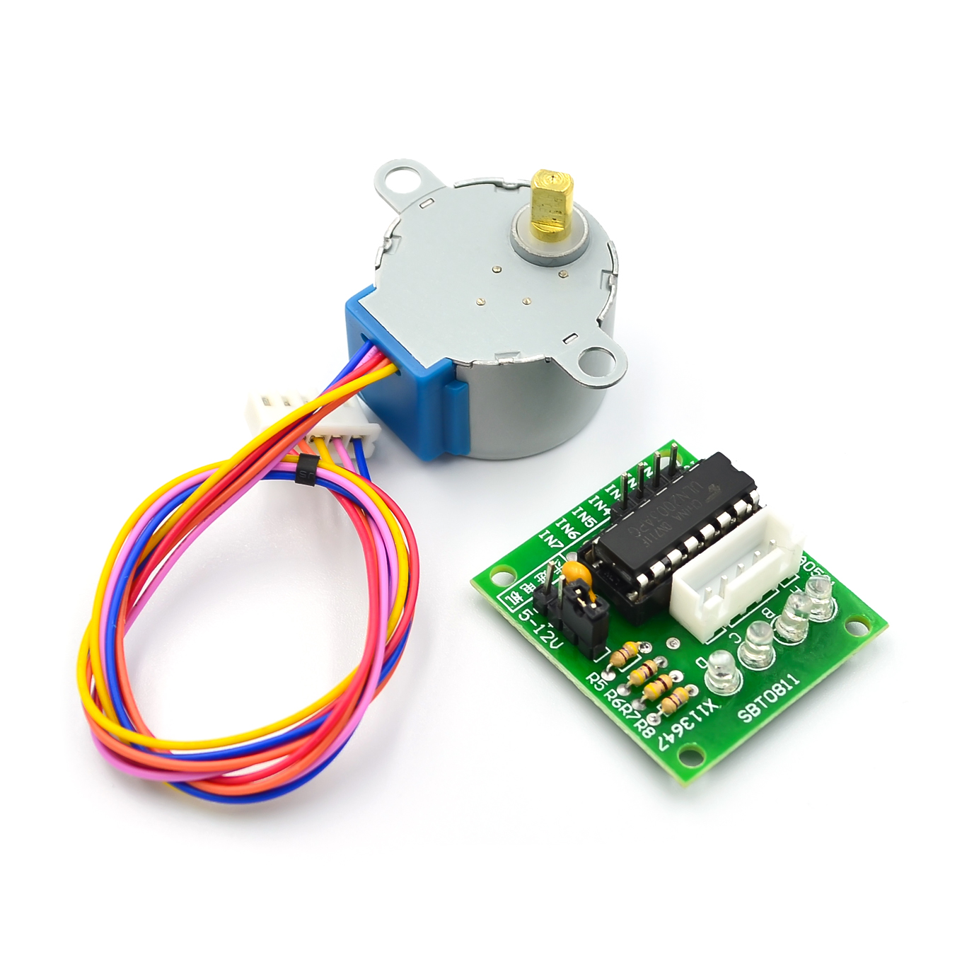
aliexpress.com
Smarter Shopping, Better Living! Aliexpress.com
the driver module handles the large currents needed
Open-source electronic prototyping platform enabling users to create interactive electronic objects.
atomic wadi
Awesome, thank you!
reef ravine
very welcome
@atomic wadi I'm waiting for parts for this http://www.brokking.net/yabr_main.html
atomic wadi
Oh nice! Placing that battery on the top makes it even more impressive... that thing is about as unstable as you can make it LOL
reef ravine
apparently putting the weight up high helps, his tutorials are very good I find
it's amazing the things you can do with a nano...
but take it from me - no matter how amazing your projects - friends and neighbors will yawn unless it BLINKS 🙂
atomic wadi
Bahahaha, you're absolutely right >__<
reef ravine
@atomic wadi that link above is for a 5 wire stepper, this is better suited https://usa.banggood.com/Geekcreit-3D-Printer-Stepstick-DRV8825-Stepper-Motor-Driver-Reprap-4-Layer-PCB-p-920162.html

www.banggood.com
Online Shopping at Banggood.com!
 proven mauve
So, I need to use some pulldown resistors for unused inputs on a chip and also for icsp headers. For the unused inputs I'm planning on a 1/10th watt bussed resistor and I want to do the same for the icsp but am I going to burn out the resistor bus if I send 5v data over the header? One of the headers is for an ATmega32U4 (like a pro micro or leonardo) I had forgotten the 32U4 doesn't need the pulldowns, but the other chip on the board does, VS1053B.
I assume to solve this I need to look at the maximum rating for the pins of the VS1053B and see how much current they can potentially draw, and then do the math from there to see if 1/10th watt will work?
atomic wadi
I concur.
proven mauve
So, if I'm using 100k resistors... and the pulldowns are on the 5v side of a 74HC4050 level shifter (5v <-> 3v) then only 53µA should be crossing the resistors at any given time, right? And it doesn't really matter that the pins are rated to 50mA because.... the maximum current over the resistors will always be below this regardless of what the pins are doing....
I think that works out to 280.9µW on the 5v side, or 0.28mW.... so I should be nowhere near blowing out 1/10W pulldowns if I'm thinking correctly...
I hope =X
cedar mountain
Your thinking is correct. Pullups and pulldowns should not be dissipating any substantial amount of power.
proven mauve
Thank you very much. I guess that's why they can fit so many into these tiny chips lol
sage mural
Hmm think i can squeeze in a 20w solenoid valve and a 60w diaphragm pump on a 6A @ 12V dc adapter?😆
 visual quarry
Can someone please help me with something?
at the bottom i labelled the button Turbo and when i press it i want it to click ludicrously fast
it would be great if u guys could help
.
wind drift
I have another small issue. I have a barcode scanner attached to my circuit. Most of the time it works fine, but sometimes I get random characters as part of the barcode.
like this:
⸮V⸮⸮⸮+A40151595*+
normal: +A40151595*+
Any ideas what the problem could be?
Maybe it's because my voltage drops from 3.3 to 2.9V?
And I assume in that case I need to use a capacitor, right?
Here are the infos from the barcode scanner:
VCC - 3.3V
Current: max. 100 mA. (I usually see less - it's kinda random?)
On-time: 3-4 sec.
visual quarry
at the bottom i labelled the button Turbo and when i press it i want it to click ludicrously fast
It would be great if u guys could help
proven mauve
@visual quarry a simple way would be to go right into that turbo == low area and make it press, then delay(10); then release;
I'm on my phone so it's not very easy to actually write the code
but that way each time it loops through the button check it will press it and release it instead of only pressing it. And a delay that short will mash the button really fast and not hold up the rest of the program too bad
something like this:
if (buttonState11 == LOW) {
Keyboard.press( 0xE9);
delay(10);
Keyboard.release(  0xE9);
}
else{
Keyboard.release(  0xE9);
}```Yes, I would try it and see how it works
wind drift
How do I fix this
it keeps saying com port busy
nevermind restart helped
Okay weird. I connected a boost-buck converter (1.8-5V -> 3.3V) to the VCC pin of the barcode scanner
when I scan it's even worse
before 1 scan out of 10 has issues
now it's 7 out of ten
cedar mountain
Can you describe how it's otherwise connected? Any chance the serial connection is not grounded, for instance?
wind drift
VCC to 3.3V
GND to GND
TX to D10
Trigger to D13 & button (other side or button to GND)
BarcodeID:
+A40151595*+
adding
BarcodeID:
+A40151595*+
adding
BarcodeID:
+A401515⸮⸮*+
adding
BarcodeID:
+A4015⸮⸮⸮⸮e⸮+A40151595*+
adding
BarcodeID:
+A40151595*⸮+A40151595*+
    code += (char)barCodeSerial.read();
  }

  if (code.startsWith("+BNR*+") == false && code.endsWith("*+") == true) {

    if (scanmode == "adding"){
      Serial.println(scanmode);
      bleuart.write(scanmode.c_str());
      Serial.println("BarcodeID:");
      bleuart.write("BarcodeID:");
      Serial.println(code);
      bleuart.write(code.c_str());

      code = "";

      singleBeep();
}```This is the code I use
cedar mountain
Is your Arduino running on 3.3V as well?
cedar mountain
Is there any chance that the scanner is expecting you to have a pull-up on TX rather than directly driving the pin high itself?
wind drift
Odd thing is.
If I attach other modules to the buck converter too it gets even worse.
If I only attach the barcode scanner to the buck converter and other modules to arduino 3.3V it is okay-ish (still errors sometimes)
I checked the voltage on the buck converter and there is no voltage drop
I don't think so.
Trigger has to be pulled down to start the scan (that's where the button is connected to GND)
Once it successfully reads the code it automatically sends it via TX to the arduino.
- Indicates start of the code
*+ Indicates end of the code
cedar mountain
Can you link to the scanner datasheet?
wind drift

That's all I have to it
But it's weird.
If I only connect the barcode scanner to the boost converter (and other modules to 3.3V arduino) it works 90% fine.
If I connect all modules to the boost converter then it only works 10% of the time.
The arduino has a voltage drop from 3.3 to 2.9V.
The boost converter stays at 3.3V always
cedar mountain
I'm not quite understanding the scenario. What is the Arduino being powered from?
wind drift
Arduino power from micro USB
So I connect the boost converter to 3.3V on the arduino
And from there to the barcode scanner
cedar mountain
So what is dropping to 2.9V?
wind drift
The arduino 3.3V pin is dropping to 2.9V when I press the scan button
cedar mountain
How is the button hooked up? It sounds like you might be directly shorting a GPIO output to ground or something.
wind drift
Arduino D13 (input) to barcode trigger
Both to button pin 1
GND to button pin 2
Orange = barcode trigger
White = D13 input
Blue = A3 input (I use this one to wake up the arduino when it's sleeping)
The button at the bottom
cedar mountain
Just out of curiosity, if you remove the orange trigger, do you still see the 2.9V drop?
cedar mountain
I must say it doesn't make a lot of sense, when the scanner is on a separate power supply from the Arduino.
wind drift
now 3,3V to 2.7V when connected
cedar mountain
What is the buck-boost being powered from?
 dapper jungle
hi im new to arduino and would really help it if someone could help me start programming
im trying to make an automatic trashcan lid with sensors but idk what to do with the code
 cyan quail
What are you using to lift the lid?
wind drift
@cedar mountain hope the drawing above is understandable
(1 wire missing from barcode scanner to arduino - TX)
cedar mountain
So, the Arduino 3.3V is coming from a 600mA LDO, so it really shouldn't droop under load. That's clearly a bad sign.
wind drift
Yeah
cedar mountain
Your diagram looks reasonable, so my best hypothesis is just that you've got something mis-wired somehow, like what you think is the 3.3V pin is really something else, etc.
wind drift
the barcode scanner takes around 100 mA
 shut stone
hi is there GOOD arduino tutorials out there?
 raw lynx
Hello, is it possible to run a loop of one function (e.g scrolling text on a LED matrix for pin 4) while also running another function (e.g. colored LEDs on pin 6)? AFAIK the only way to loop a function over and over again is the loop but I don't think you can do 2 concurrent loops. I am running off of an arduino uno
cedar mountain
@wind drift I mean, it can't hurt, but it doesn't seem like it would fix the problem, if the voltage is drooping long enough for it to show up on your multimeter. Capacitors are mainly good for mitigating microsecond-by-microsecond spikes.
dapper jungle
@wind drift just curious, what are you making
 elder hare
why does this not work (this code is copied from this assisant tool -> https://arduinojson.org/v6/assistant/)
const size_t capacity = JSON_OBJECT_SIZE(1) + 10;
DynamicJsonDocument doc(capacity);

const char* json = "{\"LPS\":\"24\"}";

deserializeJson(doc, json);

const char* LPS = doc["LPS"]; // "24"
error: 'capacity' is not a type
DynamicJsonDocument doc(capacity);

error: 'doc' is not a type
deserializeJson(doc, json);

error: 'json' is not a type
deserializeJson(doc, json);

error: ISO C++ forbids declaration of 'deserializeJson' with no type [-fpermissive]
deserializeJson(doc, json);

error: invalid types '<unresolved overloaded function type>[const char [4]]' for array subscript
const char* LPS = doc["LPS"]; // "24"
i have the lastest version "ArduinoJson 6.15.2"
wind drift
@cedar mountain I think the issue is a mix of things.
I tried to remove everything else from my code except the barcode scanning part. It seems to always get the right numbers. However at some point it stops responding & I have to restart the arduino.
With my original setup I could scan 100 times without it becoming stuck.
I also just now tried to scan again with my original setup. If I am ~5 cm away from the scanner I often get the weird characters.
If I have it 10 cm away or so it't 99% fine
so weird
north stream
@wind drift Are you powering the Arduino from your 3.3V source?
@elder hare I'm guessing compiler thinks those are function declarations instead of function calls.
elder hare
that is weird
cedar mountain
Missing an include?
elder hare
nah :S i have it included
wind drift
@north stream power from microusb
wind drift
Would it make sense for me to disable the 3.3V output from the voltage regulator
And instead connect my buck-boost converter to it
reef ravine
@wind drift from the diagram above at 1PM, it looks like the module is only powered when you push the switch?
 molten maple
i'm a bit worried about your button wiring MuckYu - you have connected the arduino pin and the pin from the scanner to the same node
reef ravine
looks like a few things will happen when the button is pushed, not sure they are all by design
 livid holly
@raw lynx there are a few ways to make it seem like the Arduino is doing more than one thing at a time. The issue is handling timings. If your code doesn't use the delay() function you can control lots of different things in your loop. I like to put each 'thing' into separate functions and then call the functions in the loop. Here is an adafruit article about handling buttons and neopixels at the same time https://learn.adafruit.com/multi-tasking-the-arduino-part-3
 raw lynx
thank you I was looking for that article!!
livid holly
@wind drift are you using D13 on the Arduino as in input? Because that pin is connected to the LED I have never tried to use that as an input. Could that be an issue?
Anyone here know how to spec a crystal. The Adafruit Feather M0 proto uses a SAMD21G that needs a crystal. See https://learn.adafruit.com/adafruit-feather-m0-basic-proto/downloads. It has 2 22pf capacitors in parallel. When I look to source crystals on digikey, they want to know the capacitance load. Is it 22pf, or is it 22*22/22+22=11pf.
reef ravine
@livid holly you can use D13 as an input, the LED will draw a little more current from whatever is driving it compared to other digital pins
livid holly
Ah, cool.
reef ravine
the caps are one on each side of the XTAL, not parallel exactly. you'll need two 22pF caps
checking spec sheet for crystal specs...
livid holly
I was having a hard time reading the spec sheet. I was in the right place, but still wasn't sure. The look parallel to me 🙂
reef ravine
there is one on either side of the crystal
see page 893, each C load cap is about 20pF (not 40pF as they would be if in parallel)
you could precisely calculate the value - but the caps have a pF or three of tolerance
cedar mountain
ST has a pretty good application note about picking crystals for STM32 chips which explains a lot of the issues and formulas.
livid holly
Ok. So, if I am looking at a schematic that shows a crystal in Mhz, and the 2 capacitors in pf. Is it as simple as picking a capacitance load for the crystal the same as the given caps?
cedar mountain
Not that simple, no.
reef ravine
cedar mountain
The external capacitors form a parallel circuit with the crystal which needs to match what capacitance the chip wants.
livid holly
Yea, I just found that PDF too, and it looks like the formula I gave before is right. If both are 22, then 22x22/22+22=11. Right?
page 12 3.3 Has the formula I think.
Er, what do you mean "what the chip wants" Ed?
reef ravine
I think you are right, just never gave it much though, most chips want ~20pF
the spec sheet for the mcu lists CLoad of 20pF
livid holly
Oh, I see. The chip itself is expecting a particular CLoad.
reef ravine
and the crystal is tuned to a particular value, CL, which is the parameter that DigiKey wants
livid holly
Great. Ok, I think I understand a lot more now. Thanks.
reef ravine
I need to go back to the books!, thanks @livid holly @cedar mountain
(I always just chuck two 22pFs and a 16MHz at my arduino and call it a day 😕 )
reef ravine
@wet crystal this probably belongs in this forum as you'll be using the Arduino IDE. take a look at https://averagemaker.com/2018/04/how-to-set-up-wifi-on-a-wemos.html

Get your Wemos talking to the world with this short and simple guide on setting up a Wemos WiFi connection via the Arduino IDE.
reef ravine
@livid holly this shows the oscillator formula a little differently, jfyr https://en.wikipedia.org/wiki/Pierce_oscillator
flint smelt
I'm confused by what's going on with the GFXcanvas8 class in Adafruit_GFX. The drawPixel function takes a uint16_t color, not a uint8_t. That's gotta be a copy/paste error, right? lol
wind drift
@reef ravine @molten maple
The white wire goes to D13 (RX arduino)
The orange wire goes to barcode scanner (TX)
The blue wire goes to A3 (input) - I use this as an interrupt to wake up my arduino after it is set to sleepmode.
They are connected to the switch (GND).
Even when I remove the blue wire from the button I still get the issue with random characters
 wet crystal
@reef ravine kk thx
wet crystal
@reef ravine Okay, so I now "know" how to setup wifi, I hope I can figure out the rest
I guess to accomplish to be secure it does connect I make some "while wifi connect" into setup?
molten maple
@wind drift , I think it is not a good idea to mix the White, Orange and Blue wires all on the same node - this could cause some sort of mixed voltages. I would recommend using a different pushbutton which has at least two poles. Keep the Arduino inputs separate from the barcode input (but they can all short to the same ground). Also you should make sure the common ground is connected everywhere, as in the ground of the arduino is connected to the ground output of the boost converter
wind drift
Hm I tried that but same problem
I kind of have a suspicion what is the issue
Once I activated the BLE function it kind of brings the issue?
  Serial.println("Please use Adafruit's Bluefruit LE app to connect in UART mode");
  Serial.println("Once connected, enter character(s) that you wish to send");

}


void startAdv(void)
{
  // Advertising packet
  Bluefruit.Advertising.addFlags(BLE_GAP_ADV_FLAGS_LE_ONLY_GENERAL_DISC_MODE);
  Bluefruit.Advertising.addTxPower();

  // Include bleuart 128-bit uuid
  Bluefruit.Advertising.addService(bleuart);

  // Secondary Scan Response packet (optional)
  // Since there is no room for 'Name' in Advertising packet
  Bluefruit.ScanResponse.addName();

  /* Start Advertising
   * - Enable auto advertising if disconnected
   * - Interval:  fast mode = 20 ms, slow mode = 152.5 ms
   * - Timeout for fast mode is 30 seconds
   * - Start(timeout) with timeout = 0 will advertise forever (until connected)
   *
   * For recommended advertising interval
   * https://developer.apple.com/library/content/qa/qa1931/_index.html
   */

   Bluefruit.Advertising.restartOnDisconnect(true);
  Bluefruit.Advertising.setInterval(32, 244);    // in unit of 0.625 ms
  Bluefruit.Advertising.setFastTimeout(30);      // number of seconds in fast mode
  Bluefruit.Advertising.start(0);                // 0 = Don't stop advertising after n seconds
}```When I disable all of this I don't get the issue
I scan 5 codes- I get 3 with random characters
 // startAdv();

  Serial.println("Please use Adafruit's Bluefruit LE app to connect in UART mode");
  Serial.println("Once connected, enter character(s) that you wish to send");

}

/*
void startAdv(void)
{
  // Advertising packet
  Bluefruit.Advertising.addFlags(BLE_GAP_ADV_FLAGS_LE_ONLY_GENERAL_DISC_MODE);
  Bluefruit.Advertising.addTxPower();

  // Include bleuart 128-bit uuid
  Bluefruit.Advertising.addService(bleuart);

  // Secondary Scan Response packet (optional)
  // Since there is no room for 'Name' in Advertising packet
  Bluefruit.ScanResponse.addName();

  /* Start Advertising
   * - Enable auto advertising if disconnected
   * - Interval:  fast mode = 20 ms, slow mode = 152.5 ms
   * - Timeout for fast mode is 30 seconds
   * - Start(timeout) with timeout = 0 will advertise forever (until connected)
   *
   * For recommended advertising interval
   * https://developer.apple.com/library/content/qa/qa1931/_index.html
   */
   /*
   Bluefruit.Advertising.restartOnDisconnect(true);
  Bluefruit.Advertising.setInterval(32, 244);    // in unit of 0.625 ms
  Bluefruit.Advertising.setFastTimeout(30);      // number of seconds in fast mode
  Bluefruit.Advertising.start(0);                // 0 = Don't stop advertising after n seconds

}
  */
If I disable all of this I scan 50 codes without any errors
Do I maybe have to change the some timing here?
It happens when I am connected to bluetooth and when I am not connected to bluetooth
reef ravine
@wet crystal I'd get that example working to make sure you are wired right and can connect to your router. Then add the http request to the code, make sure that works, then add the switch or whatever you want to trigger the request.
@wind drift it looks like pressing the switch powers up your scanner, shouldn't it be on all the time? Perhaps connect the switch to the trigger input instead? Same advice as to neojunky, break the project down into smaller chunks, get each chunk to work reliably, then add pieces as you go. I'm not sure if the issue is voltage, scanner errors, BLE errors... (If everything is 3.3V, why is the boost converter there at all?)
wet crystal
@reef ravine Oh the switch actually physically disconnects the esp from the coin cell
I think that will save more power than deepsleep
It just goes to deepsleep after activation because its possible that I wont reset it on time
reef ravine
yes turning it off is "max deep sleep"...
wet crystal
Good
reef ravine
using a CR2032 or similar?
reef ravine
As I recall the ESP8266 draws a bit of current, the coin cell may not be the best bet
wet crystal
I just saw others than run the ESP on coin cell
reef ravine
it may be possible, while experimenting I'd recommend a steady power source so power problems don't get mixed up with coding issues
wet crystal
Oh yeah thats sure
You wanna know what im about to make? You might have a big laugh 😄
reef ravine
at a minimum you'll like need to add a fairly good sized cap to smooth "spikes" as the ESP transmits
reef ravine
sure hit me up, I do need to get to work though
wind drift
@reef ravine I only want to use the scanner when I press the button. (to save battery)
I added the boost converter to see if it helps with the barcode scanner dropping the voltage. But no difference.
I disabled/enabled parts of my code 1by1 to test and the issue only happens when I have 'startAdv' active.
I assume the bluetooth advertising somehow blocks the communication somehow
wind drift
Okay another discovery
when I connect
RTS to GND
it seems to work fine
ah no nevermind
still some error
wind drift
Is there a way to temporarily turn off the advertising?
wet crystal
@reef ravine Okay, so far so good, connecting to wifi ✅ Now I gotta insert the http get request. I know the link, how do I write it to the sketch?
wet crystal
Link does look like this http://192.168.188.26/win&A=150&T=1&R=255&G=0&B=255&NL=30&NT=20&FX=0
 stuck coral
In my experience it's time to learn how to write a URI parser @wet crystal . But there might be a library for it floating around somewhere
wet crystal
Well its just a "lightswitch"
It does matter what comes back
As you might see the ip is internal
stuck coral
Yes, a parser would in the end return you a array of keys and values so you can do whatever you need to do. To do that you would make sure the HTTP request returns a 200 service code, then find the first instance of a ? or & char and use that as a pointer refrence into a parsing function.
However, I found this little reddit post https://www.reddit.com/r/esp8266/comments/43ygld/parsing_data_in_the_url_arduino_ide_for_esp8266/ that has a much better idea for you
reddit
3 votes and 6 comments so far on Reddit
wet crystal
Okay does it not work to simply use curl
Idk about that want to keep it simple
As I said, the output of the http get request doesnt matter
stuck coral
Oh I see, you want to store this URI in a sketch, sorry, totally misunderstood
stuck coral
const char link[] = "URI HERE";
wet crystal
Do I put that into global variable?
stuck coral
Sure why not, it's good practice not to but it's nice and easy.
wet crystal
// Network SSID
const char* ssid = "Nottoday";
const char* password = "Son";
const char* link[] = " http://192.168.188.26/win&A=150&T=1&R=255&G=0&B=255&NL=30&NT=20&FX=0 ";

void setup() {

  Serial.begin(115200);
  delay(10);

  // Connect WiFi
  Serial.println();
  Serial.println();
  Serial.print("Connecting to ");
  Serial.println(ssid);
  WiFi.hostname("Name");
  WiFi.begin(ssid, password);

  while (WiFi.status() != WL_CONNECTED) {
    delay(500);
    Serial.print(".");
  }
  Serial.println("");
  Serial.println("WiFi connected");

  // Print the IP address
  Serial.print("IP address: ");
  Serial.print(WiFi.localIP());
}

void loop() {


} ```Does this looks right?
Besides the serial output, im gonna remove that later
Does it really need the []?
wind drift
hm okay I just put the baud rate from my barcode scanner from 9600 to 115200. But now it gives me long numbers instead of the barcode
102104147147183254102208722214228722214163182254102
I tried to use (char) instead but it gives me random ??? symbols
stuck coral
Nah, just remove that @wet crystal , there you go, that should work
wet crystal
@stuck coral Okay, how do I proceed?
stuck coral

In this example we learn how to send get request to a web page using NodeMCU or ESP8266? As we know all webpages are HTTP protocols, GET and POST are methods of communicating between web browser and the server. Also we look towards server side php coding.
wet crystal
@stuck coral Okay when I understood right I need to copy following lines
#include <ESP8266HTTPClient.h>
http.begin(Link); //Specify request destination
int httpCode = http.GET(); //Send the request
http.end(); //Close connection
stuck coral
You got it, ESPs make it pretty easy.
wet crystal
It works
Nice
Just forgott HTTPClient http; in the loop part
Now I gotta tell it to go to deepsleep
 shrewd cove
Are there any integrated circuits i can add to my project so that my LiIon batteries can be charged via a USB C port while the Arduino is still running?
I have an ESP8266 with a bunch of buttons as a mini wireless keyboard, but i haven't figured out the charging part yet
wind drift
Well that's a bummer. Just read that the BLE on the nRF52840 has priority over SoftwareSerial. That's why my barcode is always getting chopped up
shrewd cove
@wet crystal like this one?
wet crystal
@stuck coral I dont need to wire GPIO 16 to reset since its not meant to go out of sleep by itself right?
@shrewd cove Yeah seems actually pretty neat
shrewd cove
Thanks
stuck coral
@wind drift The charger should be any charger, which can use any USB interface. For USB-C functions you need a USB-C sink. And @wet crystal you can deepsleep from a timer instead of a GPIO
stuck coral
Oh, if its not supposed to wake up then I quess GPIO IRQ unconnected will work just fine
wet crystal
Its just to save power, since I wont reset it that fast after triggering it
stuck coral
Well how do you trigger it initially?
stuck coral
OK, I'm stuggling to understand exactly what you're doing but sounds good. Have you measured power consumption of your perticiular ESP8266 board while in deep sleep?
wet crystal
No not yet
stuck coral
Note if using a coin cell, you need to make sure yor dev board has no parts on it consuming lots of power compared to the deep sleep ESP.
shrewd cove
How can i charge this kind of batteries with that charger?
wet crystal
Lipo charge module
Oh
Uhm you need an 18650 socket
There is also an ESP module which has 18650 socket + charge module on the board
 wet crystal
Yeah lol
😂
How easy is it to unsolder the esp8266 chip from the dev board?
I'm pretty talented in solderig
Also have hot air
stuck coral
With hot air you might be able to but the ground pad on the bottom is what may stop you
reef ravine
@wet crystal Glad to see you are making much progress!
 safe halo
Why is my ESP32 serial port outputting data on its own when I have nothing connected to it but when I connect something to it it stops?
Nothing is connected to it but it is still outputting
I am also having zero luck with being able to request data from an outside server.
On my page I make a request to my server for a JSON file
    fetch(url, {
            credentials: 'omit',
            mode: 'no-cors',
            headers: {
                'Content-Type': 'application/json'
            }
        })
        .then(response => response.json())
        .then(data => console.log(data))
        .catch(err => console.log(err));
My AsyncServer is set to and it loads the page but I can still not get the JSON file from the server.
  server.on("/", HTTP_GET, [](AsyncWebServerRequest *request) {
    AsyncWebServerResponse *response = request->beginResponse(SPIFFS, "/index.html", String(), false);
    response->addHeader("Access-Control-Allow-Origin", "*");
    request->send(response); });
 knotty bobcat
If I have a chararray, each containing another array, how would I go about copying the old array into the new one. I want to be able to edit entries in the new array without affecting the old one, as I will be copying from it multiple times. I've tried iterating through melodyData in a for loop, but that produces an error, so does strcpy.
char notesToPlay[][2] = {};
char melodyData[][2] = {
    {NOTE_C4, 4},
    {NOTE_G3, 8},
    {NOTE_G3, 8},
    {NOTE_A3, 4},
    {NOTE_G3, 4},
    {0, 4},
    {NOTE_B3, 4},
    {NOTE_C4, 4},
    {0, 0}
};

// How to copy `melodyData` into `notesToPlay`?
Context: I'm trying to create a non-blocking piezo snippet, and when event x is fired, I want to copy the array. In my loop function, I'm checking notesToPlay to see if there's anything that I need to handle. Also, please let me know if this is an xy problem 😅
safe halo
char melodyData2 = melodyData;
Might work??
knotty bobcat
that gives error: invalid conversion from 'char (*)[2]' to 'char' [-fpermissive]
 fallen rock
Hello, I use arduino on windows and my programs can't televersate. It's the same for Numworks. The error message is "status 1", can u help me plse
safe halo
that gives
error: invalid conversion from 'char (*)[2]' to 'char' [-fpermissive]
@knotty bobcat
try char
melodyData2(*)[2] = melodyData;
basically make them the exact same when you declare them
wet crystal
@stuck coral @reef ravine Okay. Everything works like in the flow chart. I just been curios if I can Improve the bootuptime a bit?
#include <ESP8266HTTPClient.h>
// Network SSID
const char* ssid = "Notreally";
const char* password = "brrrrrrr5r";
const char* link = "http://192.168.188.26/win&A=150&R=255&G=0&B=255&FX=0&NL=30&NT=30&NF=1";

void setup() {


  delay(10);

  WiFi.hostname("Name");
  WiFi.begin(ssid, password);
  while (WiFi.status() != WL_CONNECTED) {
    delay(10);
  }
}

void loop() {
  HTTPClient http;
  http.begin(link);

  int httpCode = http.GET();
  http.end();

  ESP.deepSleep(0);

}```{
// Get the reference to current connection
BLEConnection* connection = Bluefruit.Connection(conn_handle);
char central_name[32] = { 0 };
connection->getPeerName(central_name, sizeof(central_name));
Serial.print("Connected to ");
Serial.println(central_name);
}```For BLE there is this function when it connects to a device
How can I trigger this in my loop though?
Or is there some way to see if I am connected?
I need it for a loop
wind drift
And how can I disconnect/drop the connection?
wind drift
Bluefruit.disconnect(conn_handle); I guess I have to add this somehow in my loop but not sure how (with the conn_handle tag)
wind drift
Ok figured it out
Now my barcode scanner is properly working with BLE
I turn the BLE off when I press the trigger button. Once it detects the full barcode I turn BLE on again.
It reconnects after a second or so and sends the barcode via BLE
reef ravine
@wet crystal you could remove the delay(10); statements in void setup(), but it might take 10 - 20 seconds to connect, congrats on getting it working and happy hunting
@wind drift glad you have it figured out!
wind drift
just the reconnecting delay is a bit annoying 😄
wet crystal
@reef ravine I know it's better to keep the delay because stability
stuck coral
@wet crystal I don't know if the ESP8266 is the same, but the ESP32 requires a short delay after you put it in deepsleep, I think so yeild() is called.
wet crystal
I thought about uploading without bootloader
reef ravine
leave the bootloader, saves many headaches
the first delay (though very short) does nothing, the one in while may help, agreed
stuck coral
Yeah, sadly Wi-Fi is kinda sucky as far as low power is concerned, connecting to it and staying connected both require a lot of power when you have a tiny battery.
reef ravine
and the 8266 is a great way to experiment and learn, coin cells and long life are an advanced topic
wet crystal
It takes around 6 seconds until command is executed
reef ravine
you are in a hurry 😉
stuck coral
Certainly. Not really hating on the choice or the methodology just 6 seconds of radio usage when using a coin cell is quite a power budget.
No way to get around it
wet crystal
You think it wont make much difference using it without bootloader?
I have the ftdi232 here
reef ravine
the bootloader is what makes it understand the ftdi connection...
otherwise it thinks its a toaster oven on boot
stuck coral
Yep, then this will turn into a JTAG learning session if I'm not mistaken
reef ravine
it only helps if you are an adavnced coder and if you are running out of memory
wet crystal
So the FTDI doesnt upload from ICSP without bootloader?
stuck coral
If I remember correctly there is no ICSP interface on the ESP8266, only JTAG but I could be mistaken. The FTDI chip should just be a USB-Serial converter.
wet crystal
Okay just heard about JTAG 😄
stuck coral
Yeah, this isn't an AVR chip like a ATMEGA8266 or ATTINY where ICSP is very common, with ARM processors it is typically JTAG or SWD for programming and debugging if you don't have a bootloader. Not saying a ARM chip with ICSP is impossible but I don't think I've seen it
wet crystal
And much thanks for your help so far, really appreciate it
stuck coral
No problem, I'm saftey checking a MAC library line by line and working with a new BLE stack so this is exciting in comparision. Lol
wet crystal
Maybe someone can tell me what happening
Actually the esp does turn on again by itself
Its still on the USB
Could that also be some kind of voltage drop or so usb port shut down, since the load is too small?
stuck coral
Hm, the FTDI chip should still be consuming power and enumerating over USB even if the ESP is in deepsleep. The FTDI chip should go to a standby state when USB is unplugged.
wet crystal
Oh its still on its dev board
I just tried waiting for it to happen again, for like 10 mins now 😄
I just put this into the odd casualitys folder
stuck coral
Hm, maybe take a wire and solder from the IRQ pin to GND
wet crystal
What does affect this?
stuck coral
Well if you have a GPIO inturrupt on a floating pin, then the floating pin can trigger the interrupt, it can be very touchy.
wet crystal
Ahh okay I understand
stuck coral
Pinning it to ground will obviously keep it at 0V
 stuck coral
No, the inturrupt pin you setup for the deepsleep, the one you left disconnected because you didnt want to wake on a timer.
stuck coral
Holding RST to GND would cause it to never do anything
stuck coral
Hm, I see that with the ESP.deepsleep(0); you are supposed to use RST to wake it back up.... And it should be pulled up in the module but I'm familiar with ESP32 not 8266.
wet crystal
Yeah I cannot see an interrupt pin on the image
stuck coral
Well you can set other pins to wake from deepsleep in a IRQ, thats why you pass a varilable into .deepSleep();.
wet crystal
Oh okay the 0 is supposed to stand for the time how long it should sleep
elder hare
what's the name of the "plugin" i can install on Arduino IDE that allows me to see what the crash error was?
stuck coral
Ah, I see the ESP8266 is just a totally different beast, you are correct... but the variable is attaching a timer to a pin.... hm. Interesting but ig that works
wet crystal
Okay so the chip executed the command again. I started the stopwatch an lets see how long it will take for the next time to happen
But I cannot imagine its something else than voltage drop
Since im also using a like 3 Meter USB cable
stuck coral
Do you have a multi-meter? You are either having a floating RST or a brownout condition. Is your boin cell rechargable?
@elder hare for like the ESP32 or in general?
stuck coral
Hm, but you're using a devboard right? That should be pulling it high.
wet crystal
Yeah
stuck coral
And I know long USB cables can cause issues, mind trying a short known good cable?
wet crystal
Well its a good cable, its just the extension cord
stuck coral
Okay, but you said it's 3 meters, long USB cables can cause issues if the USB power implementation device side isn't great, I would just try a short cable to remove that as a possibility
wet crystal
Well I do meassure the time now, maybe there is some pattern
 marsh charm
Heyo, I'm looking to get into Arduino and have pretty solid experience with normal electronics. But I haven't dug into many micro controllers. I want to do things mainly with IOT and the like. Would a regular Arduino be better or an ESP32?
stuck coral
Depends on what you're trying to do @marsh charm . And idk @wet crystal, maybe someone with more ESP8266 experience here could chime in
wet crystal
Clearly the ESP
It has normal arduino functions plus tons of extras
And the price ❤️
marsh charm
Would it support the majority of libraries?
stuck coral
ESP32 if you want something really easy, beginner friendly, and you want Wi-Fi
marsh charm
Understood! I'll go get my hands on a handful then, I'd like to create a few sensors that relay data to a MySQL database.
stuck coral
Common use case. You might want to check out a InfluxDB + Grafana setup but MySQL is obviously a great tool too and it's better if you want to store more then time series data in one place
marsh charm
I already use Grafana, but am way more familiar with MySQL.
Right now Grafana is only setup with Prometheus monitoring hardware.
stuck coral
Ah, alright. ESP32 has good libraries for doing whatever you need to do Wi-Fi wise and submitting the data to your backend. Whatcha monitoring?
It also has two different frameworks to use, either Arduino or IDF, but arduino has IDF functions ported to it
marsh charm
I'm monitoring temp/humidity in various parts of a datacenter
Plus I'll probably mess around and make a mini greenhouse.
wet crystal
FML all out of the sudden the esp doesnt work anymore
stuck coral
Very cool @marsh charm. I've been working on a sensor project that will delivery gradiant maps of a greenhouse, fun stuff to play with.
Do you happen to have a diagram of your entire setup @wet crystal including the name of the dev board you're using
wet crystal
Well I didn´t changed anything
Wemos D1 Mini dev board
It does get recognized on the USB port, but it wont connect while uploading
stuck coral
Do you have a wiring diagram of your setup?
stuck coral
Did you have any serial statments in your code or is there a way to verify that GET request is still going out on reset?
wet crystal
Nope
It does seems to do nothing, no status led flash, even after hitting rst
It does show up on the computer, but uploading the code again doesnt work
Timed out waiting for packet handler
stuck coral
Is there normally a LED flash when you reset the device?
wet crystal
No
stuck coral
And do you have your multi-meter handy?
wet crystal
Yes
stuck coral
It does seems to do nothing, no status led flash, even after hitting rst
@wet crystal
So what did you mean by the LED here?
wet crystal
The blue one on the chip itself
stuck coral
Does it normally flash the LED when you hit RST?
wet crystal
It does seems to do nothing, no status led flash, even after hitting rst
@wet crystal
stuck coral
Just need to make sure because I think you have a reset circuit issue. But you saying that would mean you expect a flash, and then you said no it does not flash a LED when you reset the device normally so Im quite confused
stuck coral
Did it before it stopped working?
stuck coral
OK. Lol. So if you grab your multimeter what voltage is the RST pin at?
stuck coral
I think you have a physical reset circuit problem
wet crystal
2.9v on RST
stuck coral
Should be 3.3V, what is the output from the 3.3V pin?
wet crystal
3.2
But yeah seems reasonable
Lets try what happens when the esp is from the board
stuck coral
Hm. That could all be fine but there are two transistors in the reset circuit used for programming that Im concerned about
wet crystal
Drivers here are so crazy
Firefighters does honk while sirene is running
Since they would have issues otherwise
Super annoying 😄
wet crystal
Yeah sry for going offtopic, they just passed my window
stuck coral
idc. I like firetrucks, I grew up around the firestation. Lol
wet crystal
So esp is mixed with low melt solder
Should I go around it with the iron or use the heat gun?
stuck coral
Hm.... I think you have a solder joint out but it would be a transistor, one of the resistors connected to the transistor, or the FTDI IC
wet crystal
Ahh no I want to unsolder the whole chip from the dev bnoard
stuck coral
Ah okay, then ig, heat gun can damage it but it's probably your only option
wet crystal
Okay its off
stuck coral
Alright, fantastic
wet crystal
Okay, now I clean up the solder pads and than looking further 😄
Are there any other pins besides EN and RST that needs to be tied to vcc/gnd?
stuck coral
With the ESP pins like GPIO0 are OK floating but I dont know enough about the 8266 to give a good answer
wet crystal
One for both is okay I think?
stuck coral
Yes
wet crystal
kk thx
cedar mountain
Hang on. Pins need to have separate pull-up resistors. Otherwise you're connecting the pins together too.
stuck coral
They're pulling two pins up, one for both is right.
cedar mountain
Perhaps I'm misunderstanding. One end of the resistor is on +V. The other end of the resistor is... connected to both pins together?
cedar mountain
Gotcha. I agree... just confusion about what "one for both" meant.
stuck coral
Understood 👌🏻 Good catch if it was happening
flint smelt
I picked up a PyGamer on  and it arrived today! I'm about to have some fun!
stuck coral
Sweet, enjoy the SAMD51 if you havnt used one before
flint smelt
I'm swimming in them, I love them
wet crystal
😂
stuck coral
Oh, @cedar mountain I guess it was me who misread
@wet crystal Two pins cannot share a resistor
stuck coral
Yep
wet crystal
Well guess its time for the 2mm tht solder breadboard than
elder hare
when i call "MYINFO->SetDeviceNumLEDS(24);" from here -> https://hastebin.com/ulokeyapot.cpp
i get this
Exception 29: StoreProhibited: A store referenced a page mapped with an attribute that does not permit stores
PC: 0x40201612: setup() at C:\Users\Krist\AppData\Local\Temp\arduino_build_261466\sketch/MYINFO.h line 23
EXCVADDR: 0x00000000
why?

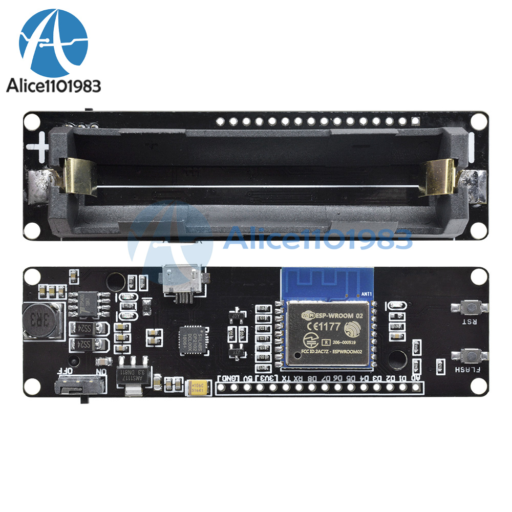
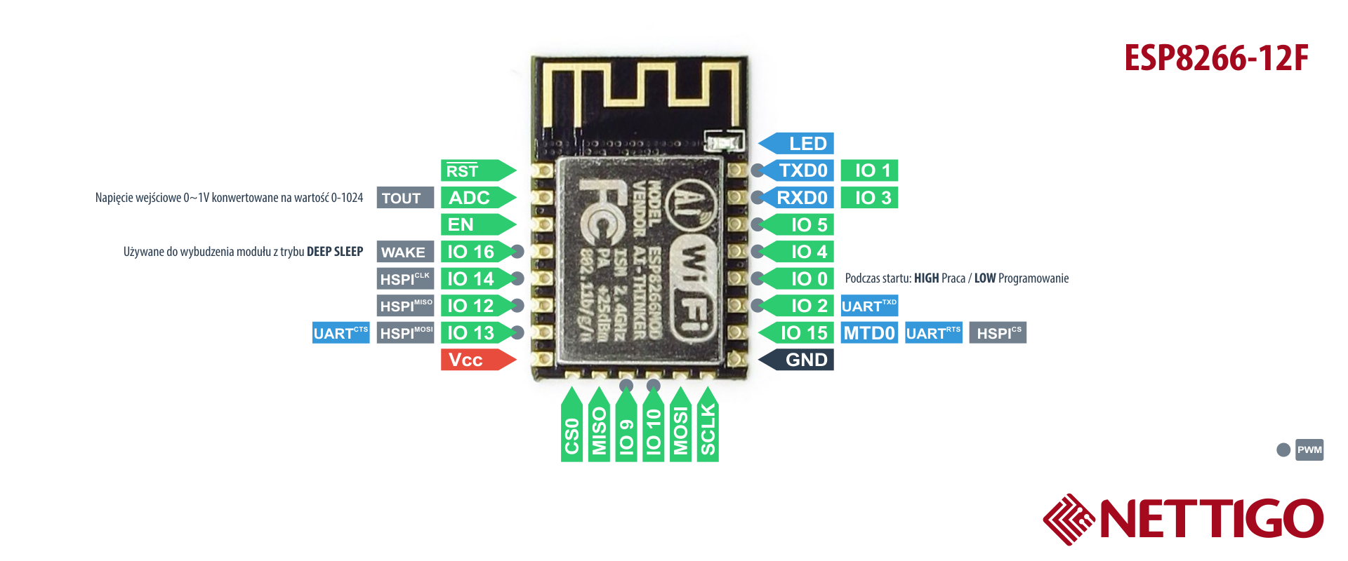 elder hare
from what i can read on google im out of heap memory 😐 w00t
stuck coral
I think you have a pointer to nowhere, but that could be
flint smelt
@elder hare did you try downloading more?
elder hare
@flint smelt what? 😆
wet crystal
downloadram.net
Download more RAM for free and instantly from our website. Free upgrade 1GB RAM - 2GB RAM - 4GB RAM - 8GB RAM - 16GB RAM
DownloadMoreRAM.com - CloudRAM 2.0
Both work. I got now 128gb of RAM on my phone 😄
When your pcb gets hold together by pure willpower
stuck coral
Spit, gafa tape and medical tubing
wet crystal
Pfff
Hotglue
Not lets find out it its still work
Well I think I should try out with a constant voltage source first
😄
 austere bloom
How do I run multiple sections of code simultaneously?
stuck coral
Well it depends on what you mean, multitasking or parallelism @austere bloom?
If you mean actually at the same time in parallel, then you need a multi-core CPU
austere bloom
Well. My specific scenario is to have a function which changes a variable's value every 1000ms and a different function which reads the output of a motion sensor
Can I do that with just 'multitasking'?
nvm I just googled a bit more and the answer is no 😦
I guess I will have to try something software side
stuck coral
Oh, you need a timer interrupt
cedar mountain
Yeah, you don't really have to do that simultaneously, per se, just do a little processing of each at a time. Read the sensor, check the time and maybe change the variable, read the sensor again, etc.
stuck coral
Setup a timer to count until 1000ms, and call a funtion to change the variable on that timer, then when you're done reset the timer and then start reading and printing the motion sensor code
Actually I agree more with @cedar mountain just millis() and a IF statment
 runic lava
can i also get help with code here