#help-with-arduino
1 messages · Page 56 of 1
 cyan jasper
 pine bramble
The one you have is the one with USB onboard?
pine bramble
Hmm, I was hoping for the USB version. It will be used by non-technical people, so I gotta keep it simple.
cyan jasper
You can add that yourself
pine bramble
Yeah, I guess so. I'd love to have your version 🙂
cyan jasper
Original or quality arduinos use Atmega16u2 chip for USB com but you could replace it with something else
If it's just gonna be used for uart (serial communication)
pine bramble
I need the USB to give the user the possibility to flash other hex files.
cyan jasper
It'll probably be just serial port then
pine bramble
If I use the 16u2, will I need to change my 328p code?
cyan jasper
No if you use 16u2 you have to program it before it can be used as serial com device
If you use Ch340 or cp210x you won't have to do another step
pine bramble
There is no tool, like the arduino IDE but for hex files, which can be used to flash through the USB?
Or do you mean that it needs to be pre flashed with a bootloader first?
cyan jasper
Avrdude
And for gui I recommend avrdudess
BTW if this is a product and uses arduino components (software included) you have to release some stuff according to arduino license
pine bramble
Turns out I could open the board file with no issues.
I edited a label in the schematic with notepad, then the file opened...
I'll have to study the license agreement, it might be sellable down the line.
cyan jasper
Faq states clearly if you are lazy
pine bramble
Well, I already kinda admitted that, so I can't really deny it.
Thanks, I'll read it.
cyan jasper
@pine bramble do you still need my template bud?
 weak walrus
Alright I’ve simplified my button but still I receive a bunch of 1/0’s and 0’s on push. 😔
 safe shell
Looks like the button grounds pin 2? Maybe the issue now is that the button is bouncing and you get a lot of instability when pushing and releasing.
If you press and hold, does it stabilize?
weak walrus
It does stabilize if I press
safe shell
Yeah, you need to debounce the input
weak walrus
I had that before but I will put it back 😄
safe shell
maybe useful if you haven't seen it: https://learn.adafruit.com/make-it-switch/debouncing
weak walrus
Is there something I am missing that should avoid this?
It seems like other people manage to get a button working
I am happy to debounce though if this is "normal" but I don't want to go down this route if I should be handling a problem higher up 😄
I think mine might be a bit different from this. Mine is bouncing when its not pushed.
(This is really helpful btw)
safe shell
It's normal to need to debounce a typical momentary button. You shouldn't get fluctuating values when it's physically static though.
weak walrus
Okay got it! I have some new buttons coming in later today so maybe I should try that... These are maybe 6 years old from my closet.
pine bramble
@cyan jasper Sorry, was afk. Yes, I'd still love to see your template.
weak walrus
I will use this time to try and setup vscode with an arduino projected haha
cyan jasper
Welp I'm not at home again 😬 😅 @pine bramble
pine bramble
Haha, dammit! Oh well, let's see later.
 raw forum
Is there someone that would like to help me tomorrow with setting up my Arduino ethernet shield to adafruit?
 reef ravine
@weak walrus try changing pinMode(buttonPin, INPUT); to pinMode(buttonPin, INPUT_PULLUP); (Looks like you removed the resistor so pin 2 floats when you aren't pushing the switch, the INPUT_PULLUP should fix it but the logic will be "backwards" )
reef ravine
what pullup does is hold the pin HIGH when the switch is open, when you push it the pin goes LOW
weak walrus
Oh I see!
that makes sense
So it'll always be 1 when the switch is open
Seriously thank you so much! I am so grateful 😄
reef ravine
yes, to "flip" your screens behavior change the logic in code
weak walrus
Will do!
I am actually a software engineer by day so that part isn't as hard for me 😅
reef ravine
pullup is very commonly used, saves parts (uses a resistor internal to the microcontroller)
reef ravine
and I'm an old hardware guy getting used to software 🙂
weak walrus
Haha well if you have questions in that realm feel free to ping me 😄
reef ravine
for this application debouncing may not be need but all mechanical switches "bounce" to one degree or another when the state changes, if you want to count how many times a switch is pressed some kind of debouncing would be needed https://learn.adafruit.com/make-it-switch/debouncing

Adafruit Learning System
When your microcontroller needs to accurately read if a switch is flipped
weak walrus
Thank you!
I already installed two more buttons and they all work perfectly 😄
my saturday is infinitely better
reef ravine
LOL, it is fun to make a few bucks of silicon bend to your will...
weak walrus
hahaha
actually my finger hurts from pressing this button so much last night 🤣
I wonder if I can find squishy ones
reef ravine
<gotta check my calendar, why is it snowing hard...>
safe shell
@weak walrus https://www.adafruit.com/?q=soft tactile
weak walrus
oh this is great thanks
reef ravine
saves on fingers...
weak walrus
amazing
reef ravine
when you get more adventurous https://www.jameco.com/z/27899-Parallax-4x4-Matrix-Membrane-Keypad_2161473.html
Buy 4x4 Matrix Membrane Keypad
weak walrus
Is there anything strange about the Rev2's Pin 2?
I have three buttons and they work for 3 and 4 but not 2...
same wiring and i swapped out the switch with another one that i know works
reef ravine
hmmm, i believe 0 and 1 are used for serial but the rest should be general purpose in / out (GPIO)
yup, looking at the UNO schematic 2, 3, 4 should all behave the same way
weak walrus
Dang.. now somehow uploads keep failing
usbhid_open(): No device found
avrdude keeps timing out
weak walrus
Restarting my computer and unplugging the arduino seemed to fix it 🙂
I think it got confused between my IDE and the Arduino IDE or something
(I moved over to using VSCode which worked for a bit then suddenly didn't haha)
pine bramble
Sounds like first psu was mains earth referenced other is floating ground
@cyan jasper I checked that and that one with floating ground is old one, and on that everything is working fine
reef ravine
@weak walrus that's life @ 16MHZ
reef ravine
can you update elements instead of the whole screen? you may need a uP with a bit more horsepower to make a snappy game
weak walrus
what is a uP? 😮
reef ravine
micro processor
reef ravine
yeah the few pixels you change the faster it'll update
you get spoiled by GHZ processors backed up by TB of RAM 🙂
wait til you try to add just one more "print" statement and RAM runs out...
weak walrus
hahaha
 odd fjord
@reef ravine just don’t use vowels — 😉
odd fjord
Saved 25 %
weak walrus
hahaha
reef ravine
@weak walrus Did you find out why all 3 buttons weren't working?
weak walrus
I did! I didn't realize that my code was failing to upload and thought it had been successful.
After I fixed that I uploaded and it worked as expected 🙂
reef ravine
cool
weak walrus
Now I am trying to read an image from the SD card and into my next set of problems but I think I can get over them 😄
reef ravine
Feel free to post questions here, I've had nothing but help from the whole community when I ask for it (there are some real geniuses in here!)
weak walrus
Thanks! I will try my hardest and then post here if I hit a wall 🙂 Everyone has been so nice
cyan jasper
@pine bramble here is my template (sorry for crudeness, I was like 14 when I drew this, and I needed to scuff the icsp header because it wasn't there for some reason.)
I guess I always added icsp headder to the projects than have it on template
It also missing 100nF decoupling caps usually works without but if it was 18 or later me he'd put them there 😅
pine bramble
@cyan jasper and AREF with 0.1u to GND not to +5V
cyan jasper
@cyan jasper and AREF with 0.1u to GND not to +5V
@pine bramble huh?
you mean 0.1uF cap to gnd for aref?
pine bramble
the "best practice" is to externally decouple the reference by connecting a 0.1u capacitor between AREF and ground
cyan jasper
well i didn't know any better back then I understand that it sets analog reading max voltage so i connected it to VCC (of chip)
yeah yeah i get it now
weak walrus
I keep getting these errors when trying to run the example tft sd script: https://gist.githubusercontent.com/jensechu/f01308e775e61f3b96adba83d5e86779/raw/5c187c8243b824b59cc2ca104b5c584474ee5d5d/arduino.sd.log
cyan jasper
but that thing work kinda ugly and full of bad practices but it become base for so many projects that it grow on me 🙂
@pine bramble but thanks for correction 👍
cyan jasper
I'm surprised I've managed to use mega8 for 328p I don't remember how i came to conclusion of those two were pin to pin compatible
pine bramble
how old are you today?
weak walrus
cyan jasper
@pine bramble uhm #general-tech ?
pine bramble
@cyan jasper Thanks 🙂
cyan jasper
consider dennis' advice too
 north stream
I thought they were pin compatible too, based on the Evil Mad Scientist board
cyan jasper
they are, aren't they?
 dark thorn
hi can someone help me with my stepper motor
i bought a cncshield and am trying to get it to work but i only hear it making noises
north stream
Could be a current problem, a voltage problem, a timing problem, a PWM problem, a wiring problem, a driver problem, or something I haven't thought of.
pine bramble
Hello, I'm following this tutorial, https://www.youtube.com/watch?v=uYIc1pLO6Xk and have all of the materials required to complete this project, but the SPI display is a bit smaller than I'd like for my project. Would I need to get a new adafruit board if I purchased a slightly larger SPI display? The new & improved SPI display in question: https://www.amazon.com/HiLetgo-240X320-Resolution-Display-ILI9341/dp/B073R7BH1B Given the board used in the tutorial https://www.adafruit.com/product/3800

Links to everything you need: https://www.sudomod.com/spooky-arduino-halloween-eyes/
Follow me on Instagram to see what I'm up to between videos: https://www.instagram.com/sudomod_wermy/
Discord server: https://discord.gg/8BDrDjQ
Buy a sudomod shirt! https://www.teepublic.com/...
What's smaller than a Feather but larger than a Trinket? It's an Adafruit ItsyBitsy M4 Express featuring the Microchip ATSAMD51! Small, powerful, with a ultra fast ATSAMD51 Cortex ...
 cedar mountain
I think you should be okay. With a quick glance at the code, it seems to be drawing the graphics directly out of flash memory, so you wouldn't need much more RAM to support a higher-resolution display.
pine bramble
Okay, thank you! I appreciate the help
raw forum
Can somebody explain me how to read things from adafruit and put on an led? I tried some things but it doesn't work, I can't seem to extract the value that is send to the arduino. It prints out "got: 1" and "got: 0" but where is the 1 and 0 stored so I can use it to turn my led on?
odd fjord
@raw forum I think your received value is an ascii character '0' or '1' not an integer 0 or 1 . Try using '0' and '1' in your switch cases... or convert the passed information from string to an integer.
raw forum
@odd fjord thank you for taking your time. I changed it to an integer but somehow it receives 990 every time but the serial above print "1" and "0"
odd fjord
there is a problem with your statement setting char x = (char *)onoffbutton.lastread I think you are setting x to the pointer to the received string.. try x = onoffbutton.lastread[0]
that will still be the ascii '0' or '1'
raw forum
Than I get this message. I'm sorry, I'm very new to this 😦
odd fjord
i made a typo taht I fixed -- onoffbutton -- not on0ffbutton
in this case x can still be a char - and use '0' and '1' in your switch statement tests
case '0':
odd fjord
you could also try just converting onoffbutton.lastread from a string to an integer with x=onoffbutton.lastread.toInt() I'm not sure if that will work, but it's worth a try...
raw forum
thankyou for your help, It printed out "48" and "49" because like you said it is a ascii. But when I tried using that 48 and 49 I got the message that mqtt was not declared in that scope.
And when I tried x=onoffbutton.lastread.toInt() it didn't work , I got a error message aswell
odd fjord
there are a few things going on -- if you use the 48/49 then they are ointegers -- don;t use the quotes if (x == 48)
raw forum
oh okay, how can I solve this?
odd fjord
how did you get it to run if it won't compile?
raw forum
I ran it first without the if and else statement
and than it printed out that 49 and 48
it was just to show you what it did and than I tried using that if and else and got the error message
odd fjord
ok -- I think the if/else should be inside your while loop
right after printing x
like the switch statement was in the previous example.
raw forum
It gives the same error 😦
odd fjord
I'll need to see your whole program -- something else must have gotten changed.
raw forum
Here is the sketch, I had this problem a few times when I tried publish as well, I don't know what it is
odd fjord
  MQTT_connect();

   Adafruit_MQTT_Subscribe *subscription;
  while ((subscription = mqtt.readSubscription(1000))) {
    if (subscription == &onoffbutton) {
      Serial.print(F("Got: "));
      Serial.println((char *)onoffbutton.lastread);
      x = onoffbutton.lastread[0];
      Serial.println(x);
      if (x==49){
        digitalWrite(2, HIGH);
      }
      else {
        digitalWrite(2, LOW);
      }
    }
  }


}

  if(! mqtt.ping()) {
    mqtt.disconnect();
  }
}

```   has a typo  -- extra close bracket -- try ```void loop() {

  MQTT_connect();

   Adafruit_MQTT_Subscribe *subscription;
  while ((subscription = mqtt.readSubscription(1000))) {
    if (subscription == &onoffbutton) {
      Serial.print(F("Got: "));
      Serial.println((char *)onoffbutton.lastread);
      x = onoffbutton.lastread[0];
      Serial.println(x);
      if (x==49){
        digitalWrite(2, HIGH);
      }
      else {
        digitalWrite(2, LOW);
      }
    }
  }


  if(! mqtt.ping()) {
    mqtt.disconnect();
  }
}
 humble folio
raw forum
humble folio
raw forum
@odd fjord It worked but it does not yet turn the LED on 😦
odd fjord
how is it wired -- is "on" high or low?
raw forum
"on" is high , so "49" is high
odd fjord
Try running a simple "blink" sketch and make sure you can torn it on/off
raw forum
I ran this sketch "void setup() {
pinMode(2, OUTPUT);
}
void loop() {
digitalWrite(2, HIGH);
delay(1000);
digitalWrite(2,LOW);
delay(1000);
}
and it blinks
odd fjord
thot does not confirm what state is HIGH/LOW
send it a '0' 48 and see if it turns on...
raw forum
I ran the blink sketch separately and on is HIGH and off is LOW
odd fjord
how do you know that? it toggles both.
raw forum
because first it ran only digitalWrite(2, LOW) and nothing happend and then digitalWrite(2, HIGH) and it turned on. I did the same with digitalWrite(2,0) and it turned off and than digitalWrite(2,1) and it turned on
like this
void setup() {
pinMode(2, OUTPUT);
}
void loop() {
digitalWrite(2, 1);
delay(1000);
}
odd fjord
ok -- sounds good -- then I have no idea why it does not turn on in your example sorry -
raw forum
No problem! thank you for your time anyway!
odd fjord
You're welcome -- good luck with it! I have to go offline -- I hope someone else can be more helpful.
raw forum
If someone else could help me, would be very much appriciated
 potent heart
@raw forum Sounds like you're almost there. First thing would be to put the debugging println() functions inside the if, right next to the digitalWrite, to make sure that it's getting to that code. If that doesn't help, please post the current version of your loop() function. It's clearly changed a few times since you posted the full sketch.
You might also put a delay(500) after the digitalWrite() temporarily just to make sure it isn't turning on then immediately turning off again or somesuch.
raw forum
@potent heart this is how I have it setup right now. Could you explain what you mean with debugging println() next to digitalwrite?
void loop() {
MQTT_connect();
Adafruit_MQTT_Subscribe *subscription;
while ((subscription = mqtt.readSubscription(1000))) {
if (subscription == &onoffbutton) {
Serial.print(F("Got: "));
Serial.println((char *)onoffbutton.lastread);
x = onoffbutton.lastread[0];
Serial.println(x);
if (x==49){
digitalWrite(2, HIGH);
delay(500);
}
else {
digitalWrite(2, LOW);
delay(500);
}
}
}
potent heart
put a Serial.print("ON") just after the first digitalWrite, and a Serial.print("OFF") just after the second one. Then you can be sure the code actually made it to those lines.
raw forum
Oh great idea, let me try
Okay so turns out, it does get to the code but somehow it doesn't get to the one that turns the led on
potent heart
Yep, so the x==49 is the problem
raw forum
indeed, maybe it has to do with the facts it is ascii , is their a way to convert that?
potent heart
try changing x==49 to x=='1'
raw forum
tried that but it is still the same 😦
one thing I can't seem to get is why it can display "1" and when I use it, it turns to 49. I know that is ascii but can I not read it and use it as a "1" aswell?
potent heart
A single character treats the two representations as equivalent. I haven't used MQTT, not sure what data type it is returning. Clearly an issue with println() interpretation. What about char(x)=='1'
Looking at the adafruit docs, they suggest this:
Adafruit_MQTT_Subscribe *subscription;
while ((subscription = mqtt.readSubscription(5000))) {
// Check if its the onoff button feed
if (subscription == &onoffbutton) {
Serial.print(F("On-Off button: "));
Serial.println((char *)onoffbutton.lastread);
  if (strcmp((char *)onoffbutton.lastread, "ON") == 0) {
    digitalWrite(LED, LOW);
  }
  if (strcmp((char *)onoffbutton.lastread, "OFF") == 0) {
    digitalWrite(LED, HIGH);
  }
}
dude it works, your method worked!
potent heart
Ok, then 🙂
raw forum
thank you!! do you use arduino with ethernet and adafruit aswell?
potent heart
Nope, that's what I was saying. I've done various arduino projects, but nowadays I use RPi zeroW's for most of my small projects. Draws a lot of current, though, so certainly not right for everything!
Never tried wireless arduinos before
raw forum
me neither, I like to use arduino's with ethernet shield, you almost always have a good connection
do you maybe have a clue why it sometime says "dropped a packet" and then needs reconnection?
potent heart
Try removing the delay() statements. Those were just for debugging.
I'm not familiar enough with MQTT and Arduino ethernet shields to give you more than a guess.
raw forum
removing the delay() did not solve it 😦 it happens to my quiet often, some on the internet say that it is because I'm sending to much data each second but that is not the case with me
and btw I really appreciate the help that I'm getting!
I found the problem
or lets say a solution haha, I removed the "ping" code
potent heart
🙂
raw forum
Great thank you for helping me out @potent heart if you need help, let me know, I dont know if I will be able to help but I'll give it a try
potent heart
np. good luck with the project!
reef ravine
@weak walrus looks like you're pushing memory limits on an UNO, 128 x 128 pixels * 24 bits/pixel is almost 50K...
from https://learn.adafruit.com/adafruit-gfx-graphics-library/loading-images
The loadBMP() function is useful only on microcontrollers with considerable RAM, like the Adafruit “M0” and “M4” boards, or ESP32. Small devices like the Arduino Uno just can’t cut it. It might be marginally useful on the Arduino Mega with very small images.

 frosty quest
Hi All,
I'm designing a module for eurorack synthesizers that allows the user to adjust the delay and speed times of a relay latching. I'm new to arduino and crappy at coding. Would anyone know how I could use a pot into analog in to change a perimeter in the code.
Kind regards,
Bruno
For reference I'm using a Chinese Arduino Uno clone.
 flint smelt
@frosty quest what have you tried so far?
frosty quest
Changing the times of speeds in this code:
Note the code is not mine. It's from: https://howtomechatronics.com/tutorials/arduino/control-high-voltage-devices-arduino-relay-tutorial/
int in1 = 7;
void setup() {
pinMode(in1, OUTPUT);
digitalWrite(in1, HIGH);
}
void loop() {
digitalWrite(in1, LOW);
delay(3000);
digitalWrite(in1, HIGH);
delay(3000);
}
I've mucked around with the low and high times.
flint smelt
So you want to read a pot and adjust those delays using the value of the pot, correct?
frosty quest
Yes.
flint smelt
Okay, let's start by adding an analog input and reading it
So pick an analog pin (say A1), in your loop function, do something like int value = analogRead(A1); and print that to get a feel for what values you're getting
Just as a start
frosty quest
And put 5v on one side of pot and other ground?
flint smelt
Yeah, and the middle to A1 (or which ever pin you want to use)
frosty quest
Cheers.
flint smelt
The Arduino IDE comes with a bunch of example programs that demonstrate a bunch of the basics, the analog input example is really close to what you're trying to do actually
frosty quest
Cheers. I had a look into that. My IDE seems to be not booting. A bit odd.
flint smelt
It can be flakey at times
frosty quest
I'm downloading it again now. Hopefully that will do it.
flint smelt
That's what I do when it starts acting up 🙂
frosty quest
Where are you from?
flint smelt
Oklahoma
frosty quest
Neat. I'm from New Zealand.
flint smelt
Awesome! I've always wanted to visit New Zealand
frosty quest
It's a nice place but it's got it's ups and downs like most places. What projects are you working on?
flint smelt
I'm working on an update to a project I did with my best friend about 6 years ago. It's a reverse geocache box that he used to propose to his wife.
frosty quest
That's very cool. I use to do geocaching, much fun.
flint smelt
With your dev board plugged into the computer, you want to go to the Tools menu and select board (choose Uno) and then choose the com port it's on, then you should be able to hit upload
flint smelt
You can run it with the other code, I'd put that line at the top of the loop function since you'll want to use the value to influence the delay lengths
frosty quest
Cheers.
int value = analogRead(A1);
int in1 = 7;
void setup() {
pinMode(in1, OUTPUT);
digitalWrite(in1, HIGH);
}
void loop() {
digitalWrite(in1, LOW);
delay(3000);
digitalWrite(in1, HIGH);
delay(3000);
}
Like this?
int in1 = 7;
void setup() {
pinMode(in1, OUTPUT);
digitalWrite(in1, HIGH);
}
void loop(int value = analogRead(A1);) {
digitalWrite(in1, LOW);
delay(500);
digitalWrite(in1, HIGH);
delay(300);
}
@flint smelt
flint smelt
Sorry, had to put the baby to sleep
Move it down above the first digitalWrite()
On it's own line
frosty quest
Thanks.
frosty quest
delay(500); to delay(A1); ?
or pinMode ?
The LED on the relay does not look happy.
Not latching with a click also.
reef ravine
@frosty quest Cheers, Would you like to take one step back to better understand how the code works?
frosty quest
That would be useful.
reef ravine
arduino programs always have
`void setup() {
// put your setup code here, to run once:
}
void loop() {
// put your main code here, to run repeatedly:
}`
so in your case you need to setup your input (analog pin A1) and your output (pin driving the relay) inside that setup routine (then in loop the "work" gets done)
once you've told the UNO which pins do what then write code to do something with those pins repeatedly, the code inside loop runs forever
so for instance inside setup would go
pinMode(in1, OUTPUT); digitalWrite(in1, HIGH);
to set the relay pin
reef ravine
you may want to give things more descriptive names relay1 rather than in1 for example. The pinMode statement wants a pin number and pin direction, you need to assign a value to relay1 or in1 , int in1 = 7; let's pinMode(relay1,OUTPUT) know you are using pin 7 (and as an output).
to put code "inside" setup put everything between { and }, the curly braces mark start and end of procedures
same for loop
and setup only needs to run once (when you power up the UNO), loop runs over and over
`
const relay1 = 7 / sets up relay1 as constantly pin 7
void setup(){ // this gets done to setup pins, etc
pinMode(relay1, OUTPUT); // sets pin 7 as an output
digitalWrite(relay1, HIGH); // sets pin 7 output as HIGH
}`
that will setup pin 7 to drive the relay (necessary, but doesn't really do anything else)
frosty quest
reef ravine
you just use 1 setup and 1 loop
flint smelt
@frosty quest you only need one void setup() {...} and one void loop() {...} (as @reef ravine said)
reef ravine
It does seem confusing at first - slowly you see the method to the madness...
frosty quest
reef ravine
yes - so far so good
now lets make the relay clack on and off, just as a test
now that setup is done we'll loop
void loop() { // do stuff here, repeatedly }
frosty quest
Many thanks. Want into a General voice chat.
reef ravine
would drive the mrs crazy:(
reef ravine
No problem, just "staying at home" for the last 8 weeks 😖
frosty quest
Same here. Where are you from?
reef ravine
New Jersey, about 30 miles west of Manhattan
frosty quest
Neat. I'm from New Zealand.
reef ravine
Oh good morning then!
reef ravine
so east of Japan? (calls there always seem 12 hours off) it's almost 2200 here
frosty quest
reef ravine
so the goal is to read a value from a pot and use that to control the on/off time of a relay?
so far so good
frosty quest
Yup. It's for switching audio, control voltage and gate signals for a modular synth. Thanks.
reef ravine
if you use the '' you can copy code here that'll format like this is code`
a relay instead of MIDI?
frosty quest
Nope for switching audio and voltage signals. With controllability.
5V 20ma at max I'm switching. So not that much.
Can I do that without relays?
reef ravine
ok, so long as it doesn't have to switch quickly
reef ravine
generally synths use MIDI control, no? Maybe I'm not following
frosty quest
Look into modular synths. Then it will make a bit more sense to you.
reef ravine
so you are using the relays to make patches?
frosty quest
They use patch cables to link each module (function) together. Using voltage and gate signals as control. Think of it as a fast controllable switch that can be used to turn of and on a signal. E.g. Cable - relay (switch) - cable.
reef ravine
and how fast do you need to be able to switch?
flint smelt
I'm more of a software guy, but it sounds like a FET might be better?
reef ravine
im thinkin....
frosty quest
Enables the user to control the time of something switching. With control of speed to said switch. Makes sense?
reef ravine
time on what scale? milliseconds, seconds, etc?
frosty quest
I don't think I've got any suitable FETs that would be suitable. I build tube amps not robots. Milliseconds or the unit bellow that.
Microseconds?
frosty quest
Yeah. I think I may of burnt it out. Still lights up according to the latching but won't click.
reef ravine
the code above would have toggled it every 3 seconds, shouldn't have been a problem at that rate
in any event,it's sounding like not a good application for a relay, at low voltage and current a FET would likely be a better choice (same principle, MUCH faster toggling)
depending on the input you are driving you might be able to do it directly from the arduino
reef ravine
more like a buzzer eh?
reef ravine
ok, if it works...
inside loop first drive the pin low, wait for some time, drive the pin high, wait, repeat
then add a feature so "wait" is set with the pot
so delay(500); waits for half a second
and we'll replace "500" with a variable - delay(timeDelay)
@mystic trail what did I say???
frosty quest
I've toasted the relay.
Still lights up but won't latch.
reef ravine
maybe you can get it to switch at 30mS - but not for long, does it need to go that fast?
frosty quest
That would be nice. I can get to light up but it won't latch at any time.
reef ravine
with the setup you have add this after:
void loop() { digitalWrite(relay1, LOW); delay(500); digitalWrite(relay1, HIGH); delay(300); }
that should turn it on and off at 3 second intervals
frosty quest
reef ravine
just need a } at the end of setup
north stream
Tubes? Vacuum tubes?
north stream
Agreed. That's what I learned on.
flint smelt
@frosty quest this should more or less be what you have so far (in total): https://gist.github.com/tjpeden/82b0d67a16601136093b4f62a9945253
reef ravine
@flint smelt Thanks, so much easier to read
flint smelt
No problem 😄
reef ravine
I really need to get the gist of doing that...
frosty quest
Thanks so much man!
reef ravine
does it now clack?
flint smelt
sorry, put int between const and the name: const int relay1 = 7;
reef ravine
opps , my bad, getting lazy using python...
flint smelt
haha right?
reef ravine
struggled so hard to get char into my head, now I can build up a string outta anything...
frosty quest
Right that seems to do it. Now to test the relay. Many thanks guys.
reef ravine
no problem
frosty quest
It's clicking! Thanks so so much!!!
flint smelt
Nice!
frosty quest
I thought I had stuffed it.
reef ravine
was probably either not cycling or trying to cycle too fast
frosty quest
Must of been. Now to get the pot working.
reef ravine
ok, see how the delay time is set?
right now its a fixed 500, we want to vary that value
I just checked quick, mechanical relays are good for maybe 5 - 10 HZ, btw
so we don't want to make the value too low
say 300 and up
reef ravine
maybe it'll work at 10Hz....
flint smelt
Well, it's a pot, so he could find the spot where it stops working
reef ravine
was going to introduce map later
flint smelt
I was going to suggest a more brute force approach lol
frosty quest
Yeah. It's all part of the fun. I'd like to be able to change both the high and low speed.
reef ravine
good enough for test!
flint smelt
Here's a good starting point: https://gist.github.com/tjpeden/4d46bab2a85636c8c5c4c9c2415c0dae
reef ravine
@frosty quest you can use 2 pots to set each speed independently
flint smelt
You can also use math to do fun stuff to the number you read in from A0
reef ravine
change your log pot to linear🙂
frosty quest
Does matter what value I use for this? I'm only using 10Ks.
reef ravine
10K pots are fine
since you're a tube guy you might want to get out the Simpson260 and measure the voltage on the wiper to make sure it goes 0 to 5 before you connect to A1
frosty quest
Haha. Just using the trusty Fluke 77.
It seems to work but it's not changing very much.
Try 50K maybe?
reef ravine
what is the voltage doing, 0 to 5?
10K is a good value, draws ~.5mA, not too much, not too little
frosty quest
It's working but not much change.
reef ravine
ok, the value at the pin ranges from 0 to 1024 when fed 0v to 5v.
frosty quest
I can't seem to get the monitor working.
reef ravine
do you know if they are linear or logarithmic pots?
reef ravine
and the voltage at pin A0 is going 0 to 5?
frosty quest
I put it on A1. It now works!
reef ravine
Excellent!
reef ravine
you can "tailor" the value now by playing with how value is calculated, no other code needs to change
frosty quest
I'm playing around with the 100. Now how can I add two pots?
reef ravine
you do pretty much the same thing electrically, just connect to A2 with the second pot
then do something like:
int pot1val = 100 + analogRead(A1); // read analog pin 1 and store it in pot1val (adding 100 means it won't go below that)
int pot2val = 100 + analogRead(A2); // read analog pin 2 and store it in pot2val (adding 100 means it won't go below that)
(changing value into 2 values, in this case representing on and off delay)
then change value to pot1val or pot2val after writing HIGH or LOW
frosty quest
I'm just going to go into the workshop and solder some stuff up.
Be back in a mo. Many thanks man!
reef ravine
no problem!
reef ravine
50K's will work, might be a bit "noisier"
frosty quest
I'll give a bunch a try.
reef ravine
I suspect the issue is in code if the voltage is correct
frosty quest
Cheers. Be back in a bit.
frosty quest
I've just soldered some Dupont connectors on to a few 10K pots. All log though.
It's working well with that said.
reef ravine
Good, at something close to the speeds you need?
reef ravine
but it at least varies now right?
frosty quest
Yeah it does. Very well to.
reef ravine
do you need to change the pots quickly (or do you set them now and again?)
frosty quest
I don't seem to.
reef ravine
I meant in actual use, do the knobs get twisted quickly?
frosty quest
In use, it would depend on the user. Being able to change them quickly is nice though.
reef ravine
I mention it because this code "blocks" meaning that the pot (or pots) don't get read until the delay is over, so it can seem "laggy" to the user
frosty quest
Right it seems to work fine for now.
reef ravine
does it buzz much at the speeds you need?
frosty quest
It would be nice if it went faster but I'll have a play with the "100".
reef ravine
well, 100 is adding 100mS to the delay value, if you go much below that the relay may not be reliable
OK, gotta get going. I think you're on the right track now, ping me with the outcome!
reef ravine
You only need analogRead for the 2 pins you are using
then replace delay(value) with delay(pot1val) or delay(pot2val)
in that way on time can be controlled by pot1val and off time by pot2val (or vice versa)
frosty quest
Thanks for that!
reef ravine
Does it work?
frosty quest
I just saw your message. Will try now.
 elder hare
when i set AutoColor to true it starts printing in serial monitor but when i set AutoColor to False it still prints in serial why?
      void AUTOCOLORMODE() {
        if (AutoColor == true){
          Serial.println("IT WORKS");
        }
      }
I can't tell you why, I can only guess. Buffering? False isn't the same as false? Loading problem? There's another printout somewhere?
elder hare
that's it.....
      bool AutoColor;

      void AUTOCOLORMODE() {
        if (AutoColor == true){
          Serial.println("IT WORKS");
        }
      }

  void loop() {
    AUTOCOLORMODE();
  }
@north stream oh and btw i just wrote "False" i know it's not the same 🙂
i have checked that i get true and false and not True and False
 obsidian flare
Quick question, im trying to power a meccano dc motor with my Arduino mega. I've got it hooked up so when a ultrasonic sensor detects something close itll stop motor etc etc. Only issue im having is i can't seem to get the motor to spin at less than 45.
pinMode(MotorOnOff, OUTPUT);
analogWrite(MotorOnOff, 45);```is there a way around this?
I was thinking its not got enough current or something?
north stream
It might be a voltage or current issue. What voltage are you using to power the motor? Are you using a motor driver circuit?
obsidian flare
No, im just using 5v into a transistor. and then pin 6 to turn on and off
flint smelt
How do I expose the onboard flash of a M4 or '840 the way CP does in Arduino?
As a USB drive
cyan jasper
A) since pulse length is really short you can't overcome starting torque
B) your psu is not adequate
C) your transistor doesn't like it
These are possible issues I come up with and I couldnt find anything on Google for Meccano DC motor @obsidian flare
Uhm also do you have any resistor on base of the transistor? Perhaps it doesn't run saturation mode
obsidian flare
Hmm so you think I should try and add more power?
Also I dont know what the motor model name it's just from something random I've had awhile.
And no theres no resistor just 5v from bored to the transistor.
And I think you're correct about the overcoming starting torque because the motor starts making a humming noise as if it's trying to turn but cant
 wind drift
void setup()  {
  pinMode(beeperPin, OUTPUT);
}

void loop()  {
  analogWrite(beeperPin, 255);

  delay(500);

  analogWrite(beeperPin, 0);

  delay(500);
}```Am I doing it wrong?
north stream
Looks reasonable to me. What happens?
wind drift
it doesn't beep somehow
But when I plug it directly into the 3V it beeps
ah okay it seems it does not get enough current on the analogpin
When I use a transistor it works
Guess it's not possible to adjust the volume with the analogpin then
north stream
Not directly, you'd need some additional circuitry
However, if you just want a fixed reduced volume, it's pretty easy.
wind drift
VDIV (A6 / P0.29): This pin is hard wired to a voltage-divider on the LIPO battery input, allowing you to safely measure the LIPO battery level on your device. If possible, you should avoid using this pin as an input because you will lose the ability to read the battery voltage. You can use it as an output just make sure to switch the pin to analog input when you want to do the battery read, then back to output when toggling pins
int val = 0; // Variable, die den gelesenen Wert speichert

void setup() {
  Serial.begin(9600); // Setup der seriellen Verbindung
}

void loop() {
  val = analogRead(batPin); // Pin einlesen
  Serial.println(val); // Wert ausgeben
}```When I read it I get ~570 as a value
Do I have to convert it somehow?
And is it correct that the charger on the adafruit nRF52840 feather express is for ~200 mAh batteries? (4.7k resistor)
currently using a 300 mAh battery
cyan jasper
That's charging current usually lipo charging current is 0.5c. C being maximum capacity
So for 200mA charing current its like 200*2=400mA battery
(You can charge with 1c too, it'll be reasonably safe for short term, long term probably changes battery to battery)
safe shell
The 570 first needs to be doubled, due to the voltage divider... then adjust based on your board ADC resolution and vref https://www.arduino.cc/reference/en/language/functions/analog-io/analogread/
cyan jasper
(more than 1c gonna be most likely for specialized batteries or batteries with good cooling)
wind drift
  Serial.begin(9600);
}
void loop() {
  int sensorValue = analogRead(A6);
  float voltage = sensorValue * (4.2/1024);
  Serial.println(voltage);
}```When I use this I get 2.35
or*2?
then 4.78
But should be between 3.7 & 4.2, no?
safe shell
Is your analog voltage reference really 4.2v?
wind drift
How do I find that out?
safe shell
what board?
cyan jasper
probably 3v3 or internal reference (IDK what internal reference do they have but most likely internal)
wind drift
yep
safe shell
Looks like 12-bit is default https://learn.adafruit.com/introducing-the-adafruit-nrf52840-feather/pinouts
but I'm not clear from reading that what the defualt analog ref voltage is
cyan jasper
check it with multimeter
wind drift
the battery?
wind drift
won't that damage the battery?
cyan jasper
@safe shell seems like programmable gain so it is user changeable
@wind drift It wont in dc voltage measurement mode
cyan jasper
I just realized something we need another point to make math work 😅
safe shell
*2
wind drift
So I have to add that to my calculation?
safe shell
I'm guessing Arduino still defaults to returning 10-bit, despite the board having 12-bit default: 570 * 2 * 3.6 / 1024 = 4.01
wind drift
And if it uses 12 bit I have to use 4095, right?
oh yes I think that's it
4.2
read with arduino
4.09 read with multimeter
ah no now it's same after reconnecting
Thanks!
pine bramble
Using the Pro Nano board as a design reference, if I want to save space on my own board, is it even necessary to have the ICSP connector?
Can't I just load the code through USB, even on a completely fresh from the factory board?
 rough torrent
Now, don't quote me on this, but I think that in order for the board to support code uploading over USB, it must be programmed with
that firmware. The only was I can think of uploading firmware without USB is using the ICSP connection.
I've also seen Feather boards use swdio and swclk pads because they use SAMD boards
I'm not an expert on this field, so I could be completely wrong.
You can upload code via usb on a Pro nano because the factory prob used the ICSP connector to load the usb firmware.
When you buy a chip with flash, it is most likely blank.
cyan jasper
@pine bramble you first need a bootloaded ic to upload code
it runs on at the start of the code. you kinda can see it in action on arduino boards first few times blink on pin 13 is bootloader running
IDK how exactly it works but i think it expect some viable UART package to arrive to start flash mode
In arduino boards reset for exact time is achieved by DTR line of UART
I dont remember how though
DTR pulses (or latches not sure) when UART (I think its USART at that point again not sure this time about terminology) ready to send packages
pine bramble
Dammit, then we're back to the issue of license.
Or writing bootloader which is a little out of my skillset 😄
cyan jasper
which resets 328p and at the starts which initiates bootloading sequence and firmware sent to chip
you don't have to I think
IDK if arduino uses customised one (licence reasons) but you can search for optiboot
ICSP is chad it just pushes program down on mcu only incorrect fuse bits can stop it
Dammit, then we're back to the issue of license.
Or writing bootloader which is a little out of my skillset 😄
@pine bramble Bro if you wanna abstract/lock things (tie them to yourself) you need to look for non gnu things (I think I remember that correctly)
which means you'll need some skillset
pine bramble
Haha, you hit the nail on the head, my man.
cyan jasper
I know what you're trying to do
I've been there
But my intention was to increase my skill set not profit 😅
pine bramble
Ugh, that word rubs me the wrong way, but yeah, it is what it is.
Lots of hours put into development, it would be nice to make something of it 🙂
cyan jasper
You might want to invest in usbasp (perhaps integrate similar thing to your circuit?)
pine bramble
I'll have to look that up.
cyan jasper
It should be open source
Atmel studio is a thing but it's like mostly register manipulation (I'm not sure their arduino things apply arduino license seems to be in gray area😬)
pine bramble
Would someone be able to look at my very messy circuit and help me with adding a potentiometer (Completely new to arduino, started today)
reef ravine
@pine bramble What are you trying to do?
pine bramble
I have a university project that I've left until the last day like an idiot. I have to design a voltmeter that uses LEDs to represent voltage
reef ravine
OK so you want to read an analog voltage and then turn on LEDs depending on that reading (like a VU meter), yes?
pine bramble
Yes, sounds right
reef ravine
using a 5 volt UNO?
pine bramble
Yes
reef ravine
and you know about setup() and loop()?
pine bramble
I'm struggling to build the circuit atm, but yeah I've looked into those
Oh, a buzzer also has to be there
reef ravine
the circuit is fairly basic, one end of the pot to ground, the other end to +5 volts, the wiper to an analog input (i.e. A0)
overvoltage buzzer?
pine bramble
I'm not too sure what you mean sorry, I can send you my circuit though will probably make more sense
reef ravine
do you have solderless breadboard?
pine bramble
It's all being done online so I'd assume so?
reef ravine
you don't have anything physical, you just need the code?
pine bramble
I have to make the circuit on a given website and code it
I have PM'd you an example of my circuit
 glass zephyr
hey guys, i have an idea for a project that i want to build, i just got my first arduino and im doing some research on it, i want to build a gamepad adapter that will allow me to use xbox one controllers and racing wheels on the xbox 360, the reason is i have a nice wheel for the xbox one and i have many racing games on the 360 and i would like to use my wheel on the 360, is it possible to build an adapter for this ?
reef ravine
@glass zephyr do you have any detail on what the wheel outputs?
glass zephyr
@reef ravine no im just starting to look into this project, i have seen many projects that use xinput but im not sure if its for xbox 360 or xbox one, the racing wheel is the logitech g920, i also have a thrustmaster tmx, both are made for xbox one. i need to know if its possible to have usb in and usb out on the same arduino or do i need to purchase a shield to get another usb input
reef ravine
it needs to use the usb into the xbox? (does the xbox have Bluetooth?)
glass zephyr
no the xbox 360 doesn't use bluetooth, the wheels both have usb to connect to an xbox one console, and the xbox 360 has usb ports
reef ravine
i'm not clear on why you need an adapter if everything is already xbox compatible
just the connectors are different? (sorry, dont have an xbox)
glass zephyr
xbox one controllers wont work with xbox 360, the drivers are not compatible with the older hardware, i need an interface that will convert xbox one controllers into xbox 360
reef ravine
probably not a good first project, might be a challenge to make an UNO act like a controller
glass zephyr
i purchased the arduino leonardo clone, 5v 16mhz
reef ravine
have you seen articles like https://www.instructables.com/id/Add-USB-Game-Controller-to-Arduino-LeonardoMicro/

Instructables
Add USB Game Controller to Arduino Leonardo/Micro: IMPORTANT NOTE: This article is for Arduino IDE version 1.6.5 (or below). To add a USB Game Controller to an Arduino Leonardo or Micro using Arduino IDE version 1.6.6 (or above) see the following Instructable: Arduino Leonardo...
more up to date url : https://www.instructables.com/id/Arduino-LeonardoMicro-as-Game-ControllerJoystick/

Instructables
Arduino Leonardo/Micro As Game Controller/Joystick: IMPORTANT NOTE: This article is for Arduino IDE version 1.6.6 (or above). To add a USB Game Controller to an Arduino Leonardo or Micro using Arduino IDE version 1.6.5 (or below) see the following Instructable: Add USB Game Co...
then it just depends if the xbox will recognize it
glass zephyr
@reef ravine yes i was just reading up on that today, i know it possible to make the usb port on my arduino to be configured as a controller, but i would still need to solder each wire to each button or axis that i want to use with this setup, maybe i can use this sketch but add a usb input with xbox one inputs then figure out how to convert them to 360 and output to the xinput usb port ?
reef ravine
i was thinking (guessing) that if the example above is actually recognized by the xbox then the next step is to break out wires from the wheel to drive the leonardo inputs, usb in and out is probably not possible
glass zephyr
@reef ravine its possible to do this, but i really dont want to damage the wheel, i still use it on xbox one and my pc, i really want to figure out this conversion to allow me to use usb from the wheel to the arduino then usb out from the arduino to the xbox 360 usb port
reef ravine
if you had any old joystick, will xbox see it? or does it need to be xbox specific?
glass zephyr
@reef ravine im going to write the xinput sketch and solder some buttons up and plug it into the xbox 360 and see if the xbox works with it, then ill go from there
reef ravine
a good first step, if you get the output going then work on bringing the older style controllers input in
glass zephyr
@reef ravine thanks for helping, i will do some testing and get back with you and let you know if this work, only tests ive seen is with a pc and not the xbox so this is a good test to make sure the sketch will work
reef ravine
bear in mind any arduino is very limited compared to a PC in terms of speed and memory
a quick Google didn't turn up much for these adapters - maybe you have a million dollar idea!
glass zephyr
lol i don't think there is enough people out there like me what still want to play the old xbox 360 games with modern controller options, but if i figure this out i will make a project page and share my steps and code
reef ravine
you've seen things like this? https://www.flashbackltd.com/products/xbox-360-controller-to-xbox-one-adapter?

Flashback Limited - Repair, Replay, Relive
High quality 3rd party product converts XBOX 360 wired controller to be used on XBOX One console - supports turbo / rapid fire function. Features: Plug and Play - no original XBOX One controller needed for verification. Enable turbo / rapid fire function on XBOX One wired ...
glass zephyr
@reef ravine yes that similar to what i want to build only in reverse, i want the new controller to work on the old console
potent heart
Cronus
The all-new CRONUS ZEN is the engine that helps connect your favorite controller to whichever console you like, add scripts, mods, and ma...
Not to dissuade you from your idea, but I think it's a lot more complicated than you realize...

One of my recent projects has been trying to modify some microcontrollers to function as XInput devices, emulating an Xbox controller. The first step in this process is to fetch and then break down the Read more…
glass zephyr
@potent heart i agree its not simple, but that device is pretty expensive and if an open source project using parts for less then $10 was an option then i think more people would use this option over the commercial option
potent heart
The hardware likely isn't too terrible. You'd pretty much just need a device that can provide USB host and device at the same time. The software will not be super simple...
Anyway, don't let us talk you out of it. You'll learn a lot whether you succeed or fail!
glass zephyr
@potent heart thanks for helping, ill post back when i get some buttons wired up to test and see if the 360 can use the arduino as a gamepad,
reef ravine
that alone will be a great step forward
potent heart
Isn't the controller input on the 360 USB?
glass zephyr
yes and they also have a RF wireless option but the console also has the ability to use a usb wired controller
potent heart
Ok, not clear to me what you're wiring ... you need USB in and USB out, with software in the middle to translate from one console to the other. Not sure it will be possible to do with an Arduino. More likely on a Ras. Pi Zero, but still not obvious.... probably are some embedded solutions out there I'm not thinking of designed to do this sort of thing (both USB modes on a single device). I know I've seen that sort of thing somewhere...
Anyway, good luck and g'nite 🙂
 lusty bear
Hello guys, can anyone help me in solving a problem of adafruit feather m0 USB does not recognize in windows 10. One second it was fine then suddenly it stopped working. I have tried restarting arduino IDE, restarting my laptop, uninstall and installing drivers manually but to no avail. This is a screenshot of my laptop devive manager.
reef ravine
https://learn.adafruit.com/adafruit-feather-m0-express-designed-for-circuit-python-circuitpython/troubleshooting-2, mentions not installing drivers for Win10
lusty bear
yeah originally i didnt install it and it works fine.
but then it didnt and i was just trying to install it to see if it helps and it didnt
 frozen garnet
hello all
i am searching binary boot file of stm32f103RCT6
reef ravine
@frozen garnet Does this help? https://github.com/rogerclarkmelbourne/Arduino_STM32/wiki/Flashing-Bootloader-for-BluePill-Boards

GitHub
Arduino STM32. Hardware files to support STM32 boards, on Arduino IDE 1.8.x including LeafLabs Maple and other generic STM32F103 boards - rogerclarkmelbourne/Arduino_STM32
frozen garnet
i have this board
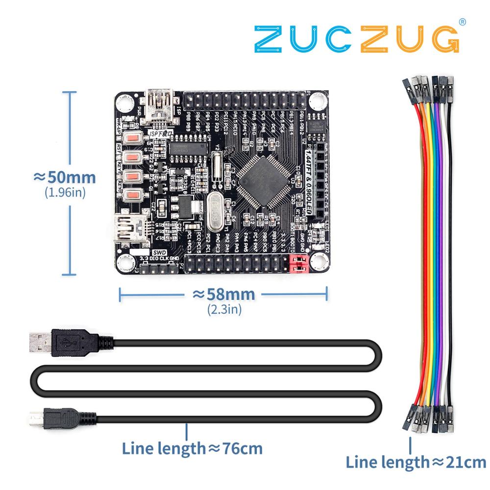
aliexpress.com
Smarter Shopping, Better Living! Aliexpress.com
which file is possible for my board
 nova comet
Hey Im working on making an 8x8 reed switch matrix for an electronic chess board project
and
i am kind of going off of this
now, my question is how can I read data from this?
do i just plug all the rows and columns into the arduino io ports?
and then after that, what data is really coming through at points a - h and 1 - 8
north stream
It's electrically the same as a matrix keypad. The way they're usually read is to pulse one column at a time and read all the rows. There are Arduino libraries for this.
There are also integrated circuits that can do it for you.
nova comet
i see. So pulsing a column would give me 0 or 1 for each element in that column, basically allowing me to understand which switches in that column are active.
and rinse and repeat per column
also
there is a physical limit on the number of io ports on the arduino
could i use a demux to shrink this?
if so, how
north stream
Yes, you can use a GPIO expander or similar. For that keypad, I'd probably pulse the rows (diode cathodes) low and have the columns connected to pins configured as inputs with pullups. There are enough I/O pins on an Arduino to do this, but you wouldn't have a lot left over.
nova comet
there are enough pins including the analog ones right
there are 14 digital?
and 6 analog?
north stream
Right.
nova comet
Could you possibly link me to a demux that you think would work for this?
im just ordering parts rn and dont want to have to order again
north stream
This one would likely do what you want, and offers enough I/O pins for the entire matrix in one chip. https://www.adafruit.com/product/732

Add another 16 pins to your microcontroller using a MCP23017 port expander. The MCP23017 uses two i2c pins (these can be shared with other i2c devices), and in exchange gives you 16 general ...
nova comet
gotcha
thank you
you think ill need anything else?
is 5v enough for this set up?
i feel it would be
but just wanna make sure
 quaint arch
Please help me in this case...
I'm doing a school project based on Vehical Speed Measuring. I don't know what would be the best and cheap motion detection sensor to be used. Please help...
rough torrent
You could use a passive infrared detector (PIR) sensor.
Simple and cheap.
cedar mountain
Can you clarify what kind of measurement you want to make? Vehicle speed sort of implies "radar" to me.
rough torrent
Maybe one of those HC-SR04 ping devices?
Please help me in this case...
I'm doing a school project based on Vehical Speed Measuring. I don't know what would be the best and cheap motion detection sensor to be used. Please help...
But @quaint arch asked for motion detection only
 mighty vigil
If you want to measure vehicle speed at range (out of the range of ultrasonic distance sensors), I'd personally use a Raspberry pi zero with OpenCV and a camera. You'd just line it up perpendicular to the road. By using the time it takes for the car to cross across the frame (along with the camera fov) you can calculate it's speed.
I doubt you'll be able to find any distance sensor that can reliably detect things above a few meters. Ultrasonic sensors definitely won't cut it.
 wooden bobcat
i've been trying to get the software off the STM site for the ST-Link. I fill out the form, get the download email, and then get a 404 error file not found. https://www.st.com/en/development-tools/stm32cubeprog.html#get-software anyone have another link for this that might work better? thanks!
STMicroelectronics
STM32CubeProg - STM32CubeProgrammer software for all STM32, STM32CubeProg, STMicroelectronics
flint smelt
@wooden bobcat I had similar trouble downloading that software. I ended up re-registering with a different email and that seemed to help? I doubt that'll help you unless you registered with a new gTLD email
potent heart
@quaint arch Another approach would be to put some sort of small embedded processor (RPi 0, Feather, etc.) on the car, and do something simple like put a photosensor on an axle to measure the time of each wheel rotation. With a little calibration, assuming no wheel slippage, you can get a very accurate speed measurement.
wooden bobcat
thanks, TangoJuliett... good idea and i did try with a second address. no joy.
flint smelt
I'd hit up their support then
It really shouldn't be that hard to download software they provide for free lol
wooden bobcat
their support widget seems to be busted, as well. 🙂 i'm thinking i'll pick something else for my project! 🙂
flint smelt
SAMD51 and nRF52840 have been my gotos lately
The STM32F405 is cool, but those two board are way less hassle
wooden bobcat
i like the samd51, haven't used the nRF52840. doesn't have to be a feather, but something about that size.
flint smelt
Both of those come in Feather for sure (Feather M4 and Feather nRF52840 Express or Feather Bluefruit Sense). I know there's an ItsyBitsy M4 and ItsyBitsy nRF52840 for smaller options... keep in mind the '840 has BLE
Tons of options! 😄
I just got in a SparkFun SAMD51 Thing+ that I'm playing with
wooden bobcat
appreciate the suggestions! thank you!
 gilded arrow
Hi I am using a powerboost 1000c for an arduino project, and I was wondering if anyone knows how to hook up the lbo to an arduino pin? I hooked it up directly and it works fine until I shut off the powerboost. Then the indicator on the board turns on. Is there a way to wire it up to an arduino pin
reef ravine
@gilded arrow What are you trying to do, power an UNO from LiPo batteries?
gilded arrow
Yes
reef ravine
the output just goes to the +5 pin (when USB is disconnected)
gilded arrow
Which output? Lbo?
reef ravine
LBO is a low battery output, you could use it to signal "time to charge the battery"
gilded arrow
Yes
reef ravine
you should use +5 and ground to the arduino, BAT and ground to the battery
gilded arrow
Yes, my problem is I want to hook lbo up to a digital pin so I can signal to the user that the battery is low
reef ravine
ahh I see, you can use any digital input pin. In code you check to see if the pin is HIGH or LOW periodically
gilded arrow
Thats what Im doing, but when the powerboost is off, the red led on the board turns on
reef ravine
what board, an UNO? , the LED on pin 13?
reef ravine
is the UNO connected by USB when this happens?
gilded arrow
No
I am running the atmega328p on a breadboard and it is completely isolated from any source other than the powerboost
So basically the schematic is lbo->d6, +5->+5, and gnd to gnd
reef ravine
just wondering what is powering the LED if the battery is disconnected...
gilded arrow
Ok, sorry I am not being descriptive enough. So the powerboost (connected to a battery) is powering an uno (essentially). When I disconnect EN and GND (turning on the powerboost) everything works as normal (ie the arduino reads the value of lbo correctly). Then when I reconnect EN and GND (turning the powerboost off) the onboard led battery indicator turns on
reef ravine
OK, when you pull EN LOW and the output stops then the +5 volt output is "low" so the LBO LED should turn on
reef ravine
why would you want to - it's telling you the +5 is too low
gilded arrow
Hmmm I think I am miscommunicating whats happening , let me record a video
Give me a few mins
reef ravine
ok
gilded arrow
reef ravine
is that red led LBO or PWR?
gilded arrow
it is lbo
reef ravine
Oh, PWR is blue?
reef ravine
wondering why LBO is always on, EN or no...
gilded arrow
lbo is originally on bc the battery is low (as it should) but then when I shut off the powerboost with lbo connected to arduino, regardless of if the battery is low or not, the led turns on
reef ravine
what is the battery voltage just by the by
gilded arrow
3.25V
reef ravine
do you have a copy of the schematic - https://cdn-learn.adafruit.com/downloads/pdf/adafruit-powerboost-1000-basic.pdf
odd fjord

GitHub
PCB files for Adafruit PowerBoost 1000 Basic (no charger) - adafruit/Adafruit-PowerBoost-1000-PCB
oops not the 100c - just a sec
gilded arrow
GitHub
PCB files for Adafruit PowerBoost 1000C. Contribute to adafruit/Adafruit-PowerBoost-1000C development by creating an account on GitHub.
I got you
odd fjord
GitHub
PCB files for Adafruit PowerBoost 1000C. Contribute to adafruit/Adafruit-PowerBoost-1000C development by creating an account on GitHub.
gilded arrow
lol
odd fjord
😉
reef ravine
I can (barely 🙂 ) make out the schematic from the webpage
so D6 is connected directly to the TPS chip
reef ravine
so it seems pin D6 is pulling the base of T1 low, when it's disconnected the base is pulled up and the LBO LED goes off
gilded arrow
ok so how would I "disconnect" d6 from it when I turn it off?
optocoupler between LBO and Bat, and then on the other side +5V and d6?
(with resistors as needed)
reef ravine
how much does the battery voltage change between EN LOW and EN HIGH?
(something is missing - perhaps part of my brain - it should be fairly straight forward)
gilded arrow
idk what you mean
and yeah I feel the same
like I havent seen anything online abt this, and I thought it was pretty straight forward
reef ravine
how about a 10K in series with LBO >> D6
reef ravine
the issue is the LBO pin is being "used" by the onboard transistor driver for the LBO LED
reef ravine
or if your soldering skills are there use the output of the transistor rather than the input
then flip the logic
gilded arrow
ohhh intersting
so I solder a small wire to the output (aka in series with the onboard led) and then use that for the input?
reef ravine
a small wire from the junction of the transistor collector and the current limiting resistor
flint smelt
Is it possible to put TinyUSB on a SAMD51 Thing Plus?
gilded arrow
ok I will try that
@reef ravine which transistor? the one right above bat and vs pin?
reef ravine
Can you see a T1 marking?
reef ravine
yes was just checking it is the only xsistor
gilded arrow
ok
so Im connecting to the single pin?
the one on a side by itself
@reef ravine ^?
reef ravine
very hard to see which pin is which, tying to find a datasheet
gilded arrow
ok thanks
reef ravine
looks like collector is pin by itself
gilded arrow
ok so a wire from the collector pin (the one by itself) through a 220ohm resistor to d6?
reef ravine
if you measure that pin it should toggle between 0 and VBatt
gilded arrow
ok I will measure it
reef ravine
between charged batt and 3.2V one that is
reef ravine
high = LED on
gilded arrow
gotcha
ok I will need to solder a wire to test it out and measure
I will @ you when I am done
@reef ravine it works!!!
thank you
reef ravine
I guess the thought was to just provide an indicator, if the transistor / LED circuit wasn't there it would have worked "out of the box" (with INPUT_PULLUP)
gilded arrow
yeah the thinking behind this does make me curious
reef ravine
so now just check D6, if HIGH bat is low
reef ravine
you are very welcome!
@flint smelt if you drill down on https://github.com/adafruit/Adafruit_TinyUSB_Arduino SAMD51 is listed, maybe a place to start, idk
GitHub
Arduino IDE support for TinyUSB stack. Contribute to adafruit/Adafruit_TinyUSB_Arduino development by creating an account on GitHub.
flint smelt
I know it works with SAMD51, I just don't know how to change the USB stack on the Thing Plus
reef ravine
<goes and sits quietly in the corner>
odd fjord
@flint smelt you can use CircuitPython on it -- it uses TinyUSB! https://circuitpython.org/board/sparkfun_samd51_thing_plus/.
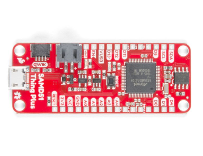
Is it power you seek? With a 32-bit ARM Cortex-M4F MCU, the SparkFun SAMD51 Thing Plus is one of our most powerful microcontroller boards yet! The SAMD51 Thing Plus provides you with an economical and easy to use development platform if you’re needing more power with minimal w...
perhaps the circuitpython repo has some clues
flint smelt
I'm trying to use this library in Arduino: https://github.com/adafruit/Adafruit_TinyUSB_Arduino
GitHub
Arduino IDE support for TinyUSB stack. Contribute to adafruit/Adafruit_TinyUSB_Arduino development by creating an account on GitHub.
flint smelt
The Feather M4 has that but the SAMD51 Thing+ does not
odd fjord
ahhh -- bummer
odd fjord
sure you can -- it's open source 😉
flint smelt
Let me rephrase that, I wonder if it's as simple as modifying the BSP and if I can figure it out lol
Probably not on an empty stomach lol
 bold sinew
Hi, for a school project we are required to make a lamp for a design class and I was stupid enough to decide to use an arduino nano and a neopixel without any experience with using an arduino. Can anyone here help me with writing some code that makes the neopixel strip glow a warm white when turned on? thanks!
reef ravine
try something like https://create.arduino.cc/projecthub/glowascii/neopixel-leds-arduino-basics-126d1a and see if it makes at least some sense
 upbeat merlin
is this
wind drift
#define WAKE_LOW_PIN  PIN_A3
#define WAKE_HIGH_PIN PIN_A4

#define SLEEPING_DELAY 30000                                // sleep after 30 seconds of blinking

void gotoSleep(unsigned long time)
{
  // shutdown when time reaches SLEEPING_DELAY ms
  if ((time>SLEEPING_DELAY))
  {
    // to reduce power consumption when sleeping, turn off all your LEDs (and other power hungry devices)
    digitalWrite(LED_BUILTIN, LOW);

    // setup your wake-up pins.
    pinMode(WAKE_LOW_PIN,  INPUT_PULLUP_SENSE);    // this pin (WAKE_LOW_PIN) is pulled up and wakes up the feather when externally connected to ground.
    pinMode(WAKE_HIGH_PIN, INPUT_PULLDOWN_SENSE);  // this pin (WAKE_HIGH_PIN) is pulled down and wakes up the feather when externally connected to 3.3v.

    // power down nrf52.
    sd_power_system_off();                              // this function puts the whole nRF52 to deep sleep (no Bluetooth).  If no sense pins are setup (or other hardware interrupts), the nrf52 will not wake up.
  }
}

// the setup function runs once when you press reset or power the board
void setup() {
  Bluefruit.begin();          // Sleep functions need the softdevice to be active.

  // initialize digital pin LED_BUILTIN as an output.
  pinMode(LED_BUILTIN, OUTPUT);
}

// the loop function runs over and over again forever
void loop() {
  digitalToggle(LED_BUILTIN); // turn the LED on (HIGH is the voltage level)
  gotoSleep(millis());        // call millis() and pass it to the sleep function.  On wake-up, millis will start at 0 again.
  delay(1000);                // wait for a second
}```In this example
Do I have to connect low pin to GND AND high pin to 3.3v?
Or only one is enough
wind drift
nevermind got it
Next question. I would like to wake up my arduino with the MPU-6050 when it detects movement. I tried connecting it to the interrupt pin, but it constantly seems to wake up on that pin.
cyan jasper
Does arduino pro mini (32u4) implement whole USB stack for bootloader?
north stream
I think it does, since that chip implements USB in hardware.
cyan jasper
wow so its a big bootloader compared to others
flint smelt
I really need either USB Mass Storage to work on SAMD51 Thing+ (in Arduino) or for my Feather M4 to spring a Stemma QT/Qwiic connector that I didn't have to solder...
reef ravine
Having <correct connector> spring into being on <board of choice> would be handy...
flint smelt
Right?
reef ravine
Soldering was much easier when I was young, A) parts were bigger B) my eyes worked 🙂
flint smelt
It's not that it would be hard, it's just that having one less thing to solder is obviously faster/easier. I'm trying to make this project as accessible as possible for beginners
reef ravine
no luck editing the BSP?
flint smelt
Yes and no
The SAMD51 Thing+ doesn't use QSPI for it's flash chip and for some reason (even though I told it to use the regular SPI) it complains about QSPI stuff not being defined... because it's not lol
reef ravine
Sounds like a trip into a rabbit hole or a search for solderless Qwiic connectors then...
reef ravine
As a hardware guy I really appreciate the level of abstraction Arduino and CP provide to noob hackers like me. My first computer was a Cosmac Elf (1978?), all done in assembly, programmed with 8 SPDT switches one byte at a time, pinMode is sooo much easier...
flint smelt
Glad I missed that, I might not have become a programmer if that's how I had to do it... I'm not much for tedious tasks lol
reef ravine
It was so tedious I went into something "real" - analog broadcast video, who knew...
flint smelt
It must have been a wild ride to see how broadcast video has changed over the years!
reef ravine
yes I literally saw it go from vacuum tubes to BGA's
(pretty easy to solder tube sockets 🙂 )
flint smelt
That's for sure!
reef ravine
Last time I needed to rework a modern piece of gear I used a 100x microscope to swap out a chip resistor, with the thinnest solder I could find the solder looked like a phone pole next to the chip
Off to (virtual) work, have fun everybody!
 earnest zenith
Not sure if anyone has used arduino for a water sensor, digital not analog. I use a PI for this now, but I want to cutover to a huzzah feather esp8266. I setup a simple button sketch and when i touch the wires I get the expected sensing. But when i but the two ends of the wires in water I don't get a connection. This method does work on the pi and I'm wondering if there are any tricks.
potent heart
pure water is not much of a conductor, normally you are relying on impurities in the water to provide enough conductance to see much. If you want to avoid any additional circuitry at all, I suspect you could do it with an analog input, but can't say I've tried.
earnest zenith
Good point. I'm trying to be super cheap, it works on the pi and I can make my own sensors, as seen in the pics in this readme: https://github.com/juanino/waterpi

GitHub
water sensors for raspberry pi. Contribute to juanino/waterpi development by creating an account on GitHub.
i'll try an analog read and see if that produces a useful sensitivity
potent heart
Yeah, will depend on how much current the input wants, and the level of impurity in the water. Try again with a little salt in the water and see what happens. I suspect the input impedance on the pi is lower than the arduino (again, haven't checked), and thus gives you better sensitivity. Wouldn't take much of a circuit to do it right, but the analog input might be a quick hack.
earnest zenith
i'm wondering if a transistor circuit by itself might be better, maybe put 5v on the transistor and let it do the switch, then read that switch.
this video https://www.youtube.com/watch?v=iLDzF6u6Bu4 seems to make it sound like it should work, but maybe the feather is not sensitive enough compared to a regular arduino? What kind of circuit could I use to "do it right" do you think?

Link to the code:
https://opensourcehardwaregroup.com/how-to-make-an-arduino-water-detection-alarm-project/
This tutorial covers how to make a simple water detection alarm with your Arduino microcontroller.
cyan jasper
@earnest zenith uhm moisture sensors for growing beds work based on capacitive sensing they can measure analog but you can make a simple opamp comparator to work as digital or do it digitally in program
earnest zenith
My target use for this is for water sensing on the floor in a laundry room in case a machine leaks or pipe breaks.
cyan jasper
I do think capacitive sensing is right way to do it because you won't have to deal with corrosion you can silkscreen the boards and be good for quite a long time
earnest zenith
Do you have an example of that somewhere I can look at?
cyan jasper
Also general humidity measurement could be useful too but probably way slower
earnest zenith
Whats the equivalent example of "button switch read" sample i might be able to look at.
earnest zenith
well, the digital read of just 2 wires didn't work. the water is not conductive enough to go high enough i guess.
so is it possible I can just read an analog value from it and fake it as high even though it's not all the way to 3.3v?
Open-source electronic prototyping platform enabling users to create interactive electronic objects.
i'm wondering if i can just analog read and see if there is enough voltage to consider "wet"
with 2 wire probes and no other circuit
cyan jasper
Search for "capacitive soil moisture sensor" for a basic start
earnest zenith
ok.
potent heart
Moisture sensing is an application where the electrodes are continuously wet, and has very different constraints. Simple leak detectors don't really require that much rigamarole.
I'm pretty sure he can make it work by just doing an analog read if the pin is available anyway.
Since it will only be wet when conducting, which should only be under very rare conditions I don't think the electrodes degrading is likely to be an issue.
earnest zenith
correct.
in the pi, i can just digital read and it works.
but on the feather it didn't. i needed to touch the wires before they conducted.
I'll try an analog read and see what i get.
potent heart
Looks like the input impedance on the ADC is very high. Saw a reported value of 50 Mohm somewhere. Note that its range apparently defaults to 1V. I suspect through water you are going to get so little current that you won't do any harm by potentially feeding it 3.3 through water, but you may need to consider a resistor if you want to be careful.
earnest zenith
yeah, the feather is only 1v safe on the analog pin.
potent heart
You could very likely make it work on one of the digital pins as well, by putting a carefully selected resistor from 3.3V to the digital input. That is, allow some leakage current to almost, but not quite, trigger the digital in, then let the water sensor "push it over the edge". Note that these are all "can I hack a quick solution" answers. If you really want to engineer it properly you should probably use a transistor 🙂
Internal pull-up/-down resistors
The ESP8266 as a microcontroller: GPIO 0-15 all have a built-in pull-up resistor, just like in an Arduino. GPIO16 has a built-in pull-down resistor.
earnest zenith
i'm using a 10k resistor to pull to ground
Should I use the internal resistor instead?
potent heart
Did you have the 10k resistor in place when you did your initial testing? If so, that's the problem. You may solve the entire issue if you switch to a ~1 meg resistor for pulldown.
Otherwise that means the resistance of the water would be have to be <10k to register a signal, which would require either a very short path or very dirty water.
earnest zenith
potent heart
Very pure water has a resistance of something like 18 Mohm/cm. Even minor impurities will bring this down a lot, but likely not to 10k.
earnest zenith
so black is grnd, green is digital pin, white is 3.3v. The other white is the other half the probe is the other white wire.
so touching the white wires works.
potent heart
Umm... red black brown is not 10k, it's 200 ohms...
Concept is fine. Just use a (much) bigger resistor.
potent heart
I would switch to ~1 Mohm
earnest zenith
so much bigger resistance, but i realize i'm a newb, can you explain why the bigger the resistance the more likely this would work? Is it because a huge resistance in that direction makes a smaller amount of voltage trigger the flow to the gpio?
potent heart
You have a digital input which presumably has a very high internal resistance. If you want to pull that input down, you need to use a resistor which is smaller than this internal resistance, or not enough current will flow to pull it down. Usually when making digital circuits, people don't worry too much about the precise value, since a 10k resistor is really only letting 0.3 mA flow, people often don't worry about the wasted power. In this case, you are basically making a voltage divider. The water is providing the resistor on one side, and the pull down resistor is on the other side, so the voltage you see on the input pin will only get pulled high if the resistance of the water is significantly lower than the value of the pull-down resistor.
earnest zenith
10k resistor DOES work, with a trick
potent heart
Trick?
earnest zenith
sticking the two probe wires in DOESN'T do it, however
if i use a plate i made for the pi,
it DOES work. uploading a pic of that in a sec.
potent heart
You will likely get better reliability still, if you use a somewhat larger resistor.
Regardless, glad that did the trick 🙂
potent heart
Yes, the large contact area and small distance between the lines will bring the resistance of the water way down.
earnest zenith
ah. you are a genius my friend.
i only have 10k and 200-300ohm resistors around. So I think the pic before that is a 10k right
gray black tan silver looks like
potent heart
No... grey black brown is 800 ohms...
earnest zenith
one sec. maybe my eyes suck.
earnest zenith
Order today, ships today. OD103JE – 10 kOhms ±5% 0.25W, 1/4W Through Hole Resistor Axial Pulse Withstanding Carbon Composition from Ohmite. Pricing and Availability on millions of electronic components from Digi-Key Electronics.
thats what it is
potent heart
brown black orange is, indeed 10k
earnest zenith
i dont know how anyone see's these colors
potent heart
Ahh, when I was young it seemed so easy. Nowadays when playing with electronics you will find me frequently wearing : https://smile.amazon.com/gp/product/B01LX473GP
earnest zenith
So is that first digit a brown? That seems like gray to me.
can you help me pick a good 1meg resistor?
maybe that?
potent heart
That is, indeed, brown.
earnest zenith
ty.
potent heart
If you plan to continue with this as a hobby, I would strongly encourage you to spend $10 bucks and get something like this (or similar): https://smile.amazon.com/Resistors-Assortment-Tolerance-Excellently-Breadboards/dp/B07D2Z45CG
Either that, or buy one of the "starter kit" raspi things which comes with a handful of various components.
earnest zenith
actually, you're right. i'm wasting a lot on one-offs, great suggestion
potent heart
It doesn't hurt to have a few capacitors and standard transistors laying around just in case.
earnest zenith
GitHub
water sensors for raspberry pi. Contribute to juanino/waterpi development by creating an account on GitHub.
this was my pi project, i am switching from the pi to feather esp8266
the pi is a little heavy for what i need, and i like the idea of the feather being cheap enough to accomplish it without an SD card purchase
when the arduino and feather say they have pullup/down resistors built in, are they usually 10k or bigger?
potent heart
10k is a pretty common pullup value. It's really just your situation, where the resistance in the other half of the circuit is potentially so large where you need a bigger one. For modern chips, 10k, is probably a lot smaller than really necessary.
 reef pollen
The Arduino uno has a Moser and a diode to protect/switch usb power, but for some reason, I'm reading 5v on my USBv pin when I power the board from the VIN pin. (any voltage. I know it's usually supposed to be more than 6.6v. Any voltage on the usbv is unexpected)
 shrewd cove
hey guys, i have a question
I have a school project that requires me to make an arduino project
and there is a particular thing i dont understand
they said they want "compiler level optimisations"
what does that mean?
like, using #define instead of const variables for example?
potent heart
This explains it pretty well: https://www.instructables.com/id/Arduino-IDE-16x-compiler-optimisations-faster-code/

Instructables
Arduino IDE 1.6.x Compiler Optimisations = Faster Code: After downloading the latest Arduino IDE (1.6.1) I was rather disappointed that some of my sketches ran significantly slower than the same sketch compiled under IDE 1.0.6. This was particularly noticeable on one of my ske...
shrewd cove
Thank you
reef ravine
@reef pollen Is the UNO an R3?
pine bramble
hello i have a question where can i learn arduino
and rasperry pi
for intermediate
reef ravine
@pine bramble There are many fine tutorials online.
For me, picking a project and then coding and optimizing it yields the most insight especially if you find a tutorial that goes into detail about the particular issue you are studying.
 pulsar beacon
//lab6a_BlinkNoDelay.ino ----------------
//Blink 2 LEDs at slightly diff freq - without delay() fcn
const int ledPin1 = 2;
const int ledPin2 = 4;
void setup() // --------------------------------------------------
{
pinMode(ledPin1, OUTPUT); // set as output
pinMode(ledPin2, OUTPUT); // set as output
}
void loop() // -----------------------------------------------------
{
static boolean ledState1 = LOW; // boolean = low or high
static boolean ledState2 = LOW; //
static unsigned long tstart1 = 0; //store last time LED was updated
static unsigned long tstart2 = 0; //store last time LED was updated
static long interval1 = 300; // blink interval in ms
static long interval2 = 295; // blink interval in ms
unsigned long tnow = millis(); // get current time
Page 3 of 4
//toggle LED1
if (tnow - tstart1 > interval1)
{
tstart1 = tnow; //reset timer
ledState1 = !ledState1; //toggle led state
}
digitalWrite(ledPin1, ledState1);
//toggle LED2
if (tnow - tstart2 > interval2)
{
tstart2 = tnow; //reset timer
ledState2 = !ledState2; //toggle led state
}
digitalWrite(ledPin2, ledState2);
}
//end
Here is my code but I need help adding an this to it to make:
t = millis();
x = amp * sin (2 * PI * freq * t);
to make it fade the leds - you need a float variable from the sin wave.
then use map() to map to 0 to 255 (the range for pwm output).
how would I code that
potent heart
You can't just use math and cast it to an int? You already have amp, just add an offset and make sure you are scaling it to the correct range, then put (int) in front of it...
 last ridge
whats an almost michael reeves- tier crappy robot idea that wouldnt be impossible for a begginer like me to make if i invested enough time into it?
 sage mural
Hi
Think i just fried my arduino :[ L-led is solid
How do you generally deal with connecting potentiometers as analog inputs?
I did the mistake (i think) follow a tutorial where a guy connects the pins directly to +5v/A0/GND
But as i turned the knob towards zero im effectively shorting the board no? is that why i fried it? if so how can i prevent this? by adding another resistor before the GND?
cedar mountain
That should be okay, unless you had the pin order on the pot wrong and were shorting 5V to ground.
 calm depot
hi, i am building a project with arduino and matlab, the code is that with a webcam it recognizes that you are a person and turns on a light system.
the problem is how to detect that a person is in front of the webcam.
if anyone can help me I would really appreciate it.
potent heart
@calm depot I think you may need to share a little more detail. Clearly you aren't running Matlab on an Arduino. And while there are some cameras which can work with some Arduino's for specific uses, this sounds like you have a PC of some sort doing the camera and recognition, and now wish to have that communicate with the Arduino to turn on lights of some sort. There are dozens of different ways of doing this sort of thing. You'll have to share more of what you have in mind to get any specific advice.
calm depot
I have a webcam connected to my pc, on my pc I run the code in matlab and from there it sends a signal to the arduino and that lights up the lights.
the problem is that I don't know how to make my webcam recognize that there is a person in front of it.
something like this
but I just want you to recognize that you are a person.
 acoustic holly
Hi is it possible to slow down wifi with arduino???
acoustic holly
yeah like slow down the connection devices have to the internet
sage mural
@cedar mountain Im sure i always used the signal (middle pin) as analog input, but i did switch the GND/5v pins a few times cus i wasnt sure which side was which...but that should be fine right?
cedar mountain
Yeah, that should be fine. Obviously I'm assuming you have a 5V Arduino rather than a 3.3V one.
sage mural
Yeah Mega 328P ?
cedar mountain
Yup
sage mural
@cedar mountain What if i try again and turn the knob towards the 0 ohm end , wouldnt that short it? Not sure what i did still that made it fry..
The uno board is OK it seems, just the Mega is fried. I have 0v when checking with a volt meter over 5v to GND pins atm
potent heart
@calm depot Hmm. Well, that's clearer at least. https://towardsdatascience.com/face-detection-in-2-minutes-using-opencv-python-90f89d7c0f81

Medium
In this quick post I wanted to share a very popular and easy way of detecting faces using Haar cascades in OpenCV and Python.
reef ravine
@sage mural turning a potentiometer changes the resistance between each end and the wiper, the resistance end to end stays the same. the voltage on the wiper will change from 0 to 5 volts as it is turned from one end to the other. it's that voltage that is being measured by the analog pin (A0). flipping the ends is no problem, that will change whether the voltage goes up or down when the knob is turned in one direction.
@sage mural On the Mega, with power removed, measure across the fuse with the ohms function, it should read nearly zero. If it doesn't then the fuse F1 "popped", hopefully protecting the rest of the Mega. You could also try to power it up using the external power jack if you have a 7 to 12v "wall wort" power supply that fits and has positive on the center pin.
Mega power fuse location
cyan jasper
@sage mural yeah adding another resistor before gnd would solve it but you'll lose some resolution because voltage divider doesn't cover whole range
 glossy onyx
hello all, i am trying to make a motion sensor that turns on my RGB LED for a few mins then shutts off. i have a simple code to work the sensor but not the RGB... i am as new to micro controllers and would like some help with the code. here is what i have and the lays out. please note its not much
int ledPin = 13;
int pirPin = 9;
int val = 0;
void setup()
{
pinMode (ledPin,OUTPUT);
pinMode (pirPin, INPUT);
}
void loop ()
{
val = digitalRead(pirPin);
digitalWrite(ledPin,val);
if (val == 1)
digitalWrite(ledPin,LOW);
}
odd fjord
Have you tested just turning on/off the LED -- RGB LEDS usually have more taht one pin or they are Neopixels that require a whole different way of operation.
besides -- you need a current limiting resistor with an LED.
glossy onyx
i tested the LED "Red lonly one" and it works but trying to figure out the code for RGB... not 100% sure whati need to do...
odd fjord
waht do you mean RGB -- the NeoPixel string?
 severe umbra
This is a bit of a weird project I got going on and its been a few years since i touched electricity and arduino. I can't explaiiin too much out of reasons but say we have a black box that requires more current than the arudino can put out. What I wanna do is hook this blackbox in a battery pack and control the current going to it with an arduino.
I googled a little around and I find a lot of complex looking circuits. So the question here is in my mind I only need a transistor for this and ofc some resistance. I lost all my electronics and i am rebuying a little but my budget is super low soo haha.
odd fjord
@glossy onyx take look here -- lots of information and examples https://learn.adafruit.com/adafruit-neopixel-uberguide
glossy onyx
thanks. ill check it out
north stream
@severe umbra Might start here https://learn.adafruit.com/transistors-101
severe umbra
Yeah thats my point I kinda know when to use transistors but this googling kinda threw me off guard. In my head ill only need a transistor but i see a few different here both with capacitor, some with some things im not 100% sure what is just wanted some confirmation that i only need a transistor + resistor etc or
like if i wanted just an LED where i can use PWN to regulate the brightness
north stream
Usually you just need a transistor and a resistor or two.
north stream
You'll want a current limiting resistor for the LED as well.
severe umbra
oh true
maybe i should wait a little build up some compoments and try around a little
north stream
but that should work fine with a garden variety NPN transistor
severe umbra
i sorta got it still then haha thanks sorry for the very weird questions ^^"
north stream
it's tricky when you don't even know what to ask: we've all been there
 wintry heart
So I found this youtube video where someone makes a simple automatic plant watering system ( https://youtu.be/Y73twlAdcLs ) and in his video he uses a relay to power a water pump I just got into arduino and I want to know how I can instead make an led light up when the soil moisture is low. Any help is much appreciated thanks :)

code and scheme:
https://github.com/wojtii/arduino/tree/master/plant_watering_system
Thanks for watching. Keep in mind that you will probably need to personalize your project for your needs. Please make sure to work in safe environment (it is electronic!). I do not take any r...
Here is schematic he used
 modest meteor
you can remove pretty lot from that schematic I bet. leaving boards for sensor and uno. you just directly drive a led from uno I guess
wintry heart
I'm just confused where the 3 leads are in the breadboard which ones should I attach to an led?
modest meteor
good question, someone more knowledgable will be able to help 😄
wintry heart
Hopefully lol
safe shell
@wintry heart For an LED, you'll want a ground wire, and a current-limiting resistor, see: https://learn.adafruit.com/adafruit-arduino-lesson-2-leds/blinking-the-led make sure to observe the polarity of the LED
wintry heart
@safe shell where should I put the led on the circuit as there are 3 wires going into the breadboard from the moisture sensor. Thanks!
safe shell
I haven't watched the video, but it looks like the only purpose of the breadboard is to share the 5v power among the three devices. The only change really is that the relay and everything to the right goes away, and the what was the relay signal wire now goes to your LED circuit (LED oriented properly + resistor of appropriate size in series).
the photo is a little blurry, but the black wires appear to be ground, and the blue wires appear to be the two signal wires from the Uno GPIO pins
I'd suggest working on each piece separately, then putting them together (e.g., try wiring up and coding sensor first, then try LED) ...check out learn guides like the one I posted
wintry heart
So the black gnd wire and the 5v red wire are the wires I should connect to the led because it seems those are what powers the relay
safe shell
well, then your LED will always be on (and absolutely don't forget about the resistor and the LED polarity)
you want to drive the LED from an output pin on the UNO so your code can control when it goes on and when it goes off
(again... read the guide I posted)
a relay needs power, ground, and signal.
you only need signal and ground (unless you need a super-bright LED)