#help-with-arduino
1 messages · Page 54 of 1
 deft scroll
@safe shell My friend you are the MAN...or WOMAN...err THANK YOU IT WORKS turns out it's the anything else pins on the bottom and I deleted it so I had no idea it was there!! THANK you so much!
 safe shell
@deft scroll Cool! Glad you got it working!
@tawdry merlin Give me a second, I'm going to install your board in Arduino so I can actually compile and not just look at it 😉
 tawdry merlin
ok
safe shell
While I'm doing that, I'd suggest tracing through the code and making sure the sequences make sense to you.
tawdry merlin
i can give u the save file for the project
this is where i got my library from
my teacher gave me this linkl
safe shell
Thanks, it's downloading now.
tawdry merlin
ty so muhc once again, im soo gratfulf or this, wish i can give u something for ur help so far
safe shell
That's what we're all here for. Since this is an assignment, I'm trying to guide you to find your own solutions rather than be too specific 😉
safe shell
@tawdry merlin sorry, got pulled into a local support issue. I wasn't able to get the heltec board definition recognized, so I'll stick with manual process rather than wrestle with that longer.
tawdry merlin
should i give u remote access for the thing?
or just screenshare
and text me the changes
safe shell
No, let's just try to logic through it.
tawdry merlin
ok
safe shell
You removed the extra brace in line 27? I commented out all of the heltec lines and it compiles without that
safe shell
line 29... I think that's extra
tawdry merlin
ok removed it
safe shell
isn't the code following that supposed to be in setup() also?
So it should compile now (even if the order is not yet as you want it)?
tawdry merlin
it is in the setup
safe shell
yeah, that brace was throwing things off. should be better now.
safe shell
🤞
tawdry merlin
the scene is not on, and the serial monitor is freaking out now XD
Rebooting...
ets Jun 8 2016 00:22:57
rst:0xc (SW_CPU_RESET),boot:0x17 (SPI_FAST_FLASH_BOOT)
configsip: 0, SPIWP:0xee
clk_drv:0x00,q_drv:0x00,d_drv:0x00,cs0_drv:0x00,hd_drv:0x00,wp_drv:0x00
mode:DIO, clock div:1
load:0x3fff0018,len:4
load:0x3fff001c,len:1044
load:0x40078000,len:8896
load:0x40080400,len:5816
entry 0x400806ac
that is being spammed on serial monitor
safe shell
the ESP32 isn't happy, but it's just a code thing, we'll look for it
tawdry merlin
ok
safe shell
so it reboots over and over?
tawdry merlin
yeah
i just keeps refreshing
and that text comes back
the one i sent
and the screen also isnt booting as well
but its progress
safe shell
Is there still a Heltec.display->clear(); somewhere near line 20? that should be later. You can't do anything Heltec until after the Heltec.begin...
tawdry merlin
void setup(){
Serial.begin(115200);
pinMode(LED,OUTPUT);
digitalWrite(LED,HIGH);
delay(300);
Heltec.display->clear();
WIFISetUp();
WiFi.disconnect(false);//重新初始化WIFI
delay(1000);
WiFi.mode(WIFI_STA);
WiFi.setAutoConnect(true);
yeah i see it
safe shell
BUT... notice that Heltec.begin(... is in WIFIScan(), which is called by WifiLoop(), which is never called. So that Heltec initialization stuff really needs to be up in setup()
tawdry merlin
Heltec.display -> display();
Heltec.begin(true /DisplayEnable Enable/, false /LoRa Enable/, true /Serial Enable/);
delay(800);
Heltec.display -> clear();
safe shell
and in the right order
tawdry merlin
so i put that in the setup?
safe shell
see the examples... Heltec.begin should be the first thing. it initializes that object so you can work with it
safe shell
sorry, I wasn't clear... all of the setup code must be inside the setup() function, but you need to do the Heltec.begin(... before any other Heltec... actions
tawdry merlin
WAIT THE LED IS ON
ITY WORKS
the screen shows the wifi setup
and on serial monitor the time
but it says connnection failed
i think it didnt connect to the wifi right
safe shell
Can you cut and paste a relevant section from the serial output? again with three backticks before and after
tawdry merlin
ok
holdon
wait now it stopped working
load:0x3fff001c,len:1044
load:0x40078000,len:8896
load:0x40080400,len:5816
entry 0x400806ac
Serial initial done
y
on my screen it says Connecting...failed
Wifi setup done
and OLED initial done
wait
nvm
re uploading code worked
Friday, April 10 2020 18:50:00
Day of week: Friday
Month: April
Day of Month: 10
Year: 2020
Hour: 18
Hour (12 hour format): 06
Minute: 50
Second: 00
Time variables
18
Friday
but the screen has same error
this is bascially what i see so far
the time works
not the wifi
usually the wifi refreshes
safe shell
what do you mean by "usually the wifi refreshes"?
tawdry merlin
when it fails to connect
it goes back to "connecting"
untill it connects
it was what the sample code did
safe shell
Looks like it should try 10 times
tawdry merlin
yeah
safe shell
can you point me to the example this is from?
safe shell
you could try to increase the count from 10 to something else, 10 only gives 5 seconds, could take longer. Has it ever connected?
tawdry merlin
yeah it connected in the past
safe shell
(obvi double-check your ssid and password too)
tawdry merlin
this is an example code
this one works
wait
now the example code doesnt work on my ESP32
safe shell
OK, so why don't we each try to compare the two and find out the difference, why one works and the other doesn't. You could save your current and reload the example just to verify it's all still fine
ah
with your ssid & pw?
tawdry merlin
OHH
i forgot to put that
no still same issue
the selected serial port failed to excecute script esptool
does not exist or ur board is not connected
safe shell
oh, that's different... may need to check for firm cable connection, even try reset the board
tawdry merlin
it works just fine on the project we are working on but the example code is giving that error
i reset it and such
switched cables just now
ok i told my teacher my concern
and it was the opposite
he wants the time on the screen
and the wifi works aslong as the time shows up
safe shell
OK, probably best to focus on your code then. I need to take a break for lunch. But I'd suggest for now:
- reviewing your code, make sure things are in the sequences you want
- look at the redundant wifi setup code in
setup()andWiFiSetup()- you only want to do that once, the WiFiSetup looks more robust and has your OLED display code in it - try to increase the loop count, add some Serial.print statements so you can trace the code execution in more detail
- don't forget about the string format stuff in the time code, there should be plenty of web resources to find docs on what your teacher wrote
tawdry merlin
i scrapped all that code in the end
i took an example code and I just need to make it go on the screen instead of serial monitor
#include "time.h"

const char* ssid     = "REPLACE_WITH_YOUR_SSID";
const char* password = "REPLACE_WITH_YOUR_PASSWORD";

const char* ntpServer = "pool.ntp.org";
const long  gmtOffset_sec = 0;
const int   daylightOffset_sec = 3600;

void setup(){
  Serial.begin(115200);

  // Connect to Wi-Fi
  Serial.print("Connecting to ");
  Serial.println(ssid);
  WiFi.begin(ssid, password);
  while (WiFi.status() != WL_CONNECTED) {
    delay(500);
    Serial.print(".");
  }
  Serial.println("");
  Serial.println("WiFi connected.");

  // Init and get the time
  configTime(gmtOffset_sec, daylightOffset_sec, ntpServer);
  printLocalTime();

  //disconnect WiFi as it's no longer needed
  WiFi.disconnect(true);
  WiFi.mode(WIFI_OFF);
}

void loop(){
  delay(1000);
  printLocalTime();
}

void printLocalTime(){
  struct tm timeinfo;
  if(!getLocalTime(&timeinfo)){
    Serial.println("Failed to obtain time");
    return;
  }
  Serial.println(&timeinfo, "%A, %B %d %Y %H:%M:%S");
  Serial.print("Day of week: ");
  Serial.println(&timeinfo, "%A");
  Serial.print("Month: ");
  Serial.println(&timeinfo, "%B");
  Serial.print("Day of Month: ");
  Serial.println(&timeinfo, "%d");
  Serial.print("Year: ");
  Serial.println(&timeinfo, "%Y");
  Serial.print("Hour: ");
  Serial.println(&timeinfo, "%H");
  Serial.print("Hour (12 hour format): ");
  Serial.println(&timeinfo, "%I");
  Serial.print("Minute: ");
  Serial.println(&timeinfo, "%M");
  Serial.print("Second: ");
  Serial.println(&timeinfo, "%S");

  Serial.println("Time variables");
  char timeHour[3];
  strftime(timeHour,3, "%H", &timeinfo);
  Serial.println(timeHour);
  char timeWeekDay[10];
  strftime(timeWeekDay,10, "%A", &timeinfo);
  Serial.println(timeWeekDay);
  Serial.println();
}```anyone know how to put this on the built in screen?
safe shell
@tawdry merlin Is it connecting now?
You should be able to pull over the blocks from your old code... Heltec.begin(... and those few lines into setup() and the rest where they make sense in loop()
or into a similar function as the old one that you call from loop()
 long geyser
I have a noob question.
I'm very new to Arduino and microcontrollers, and am working on the larger project that involves uploading code to an ESP8266. I have the ESP8266 (v2.6.3) board installed, have the NodeMCU 0.9 board selected, and have the correct COM port selected.
I'm trying to compile someone's script that includes a few different libraries/dependencies (AH_EasyDriver.h, ArduinoOTA.h, PubSubClient.h, and SimpleTimer.h). When I compile the script, the debugger kicks back a bunch of errors. Most referring to undefined references. From what I know about technology, my current guess is that it's not reading my dependency files correctly. My dependencies are in the same folder as my script, and it looks like one of them is importing properly:
I've pasted my error in pastebin, and can copy it here if preferred.
https://pastebin.com/1EzkTm4R
wait, i think I got it
tawdry merlin
@safe shell sorry i had my lunch break too
i think i need to scrap that code and the code i sent just now, i simply gotta get it on the screen and noty the serial monitor
long geyser
I made it a bit further, but I'm getting this now:
sketch\ArduinoOTA.cpp: In member function 'void ArduinoOTAClass::_onRx()':
sketch\ArduinoOTA.cpp:189:34: error: 'U_FS' was not declared in this scope
 if (cmd != U_FLASH && cmd != U_FS)

                              ^
exit status 1
Error compiling for board NodeMCU 0.9 (ESP-12 Module).
Any thoughts?
safe shell
@tawdry merlin Sure, just start from whatever example you think is closest. Like I said before, I think you have all of the pieces you need, they just need to be put together to do what you want. Even if your main goal is display on the OLED, Serial.print(... is a very useful tool for debugging and tracing through your code when it's running.
BTW, I was able to load and run the previous example on a different board. No Heltec OLED display, but I can help check the flow if you get stuck.
 warm token
I bought one of these IR extenders - anyone know if there's any kind of standards around them, like what voltage/current they take?
https://www.amazon.ca/gp/product/B01H5A3IWY
 north stream
You could run it from a medium voltage supply and measure the current through it and the voltage drop to determine if it's a plain IR LED, or one with a current limiting resistor.
 vagrant current
So I have a tp4056 (https://www.google.com/search?q=How+to+make+a+18650+battery+charge+indicator+with+a+tp4056&rlz=1C1CHBF_enUS819US819&sxsrf=ALeKk02u_D6e5Hg7MWi8iFOGhVRcH3Vymg:1586569060524&tbm=isch&source=iu&ictx=1&fir=mniUAoZY-SRwBM%253A%252CA_YNoMQddZm-0M%252C_&vet=1&usg=AI4_-kQwwa2sn6qubkC3ExORCvDZEr6lyQ&sa=X&ved=2ahUKEwiSj46qnt_oAhUTrJ4KHVctBgUQ9QEwG3oECAYQFg#imgrc=mniUAoZY-SRwBM:) chip to charge 18650 batteries and I was wondering how I can also use this chip to tell how much battery is left in them
What I am looking for is the 4 led systems that you see on portable chargers for phones and such
And how can I use that chip to charge two batteries
 cedar mountain
For battery-fullness, the chip doesn't really help much, but if you just need a rough estimate, you can use a few analog comparators to check the charging voltage and light up LEDs in response.
For two cells, you can hook them up in parallel and charge them together IF they have about the same charge level to start with. If you're not sure about that or want to be safer, put some low-value resistors between them to allow the charge levels to equalize.
 proven mauve
Anyone familiar with using MIDI.h for USB? I have a physical serial midi jack and a USB cable. I can send and receive on the serial jack, I can receive on the USB and send it to the serial, but I can't reliably send out over USB
setting USB or midi baud rates for Serial.begin didn't seem to help
tawdry merlin
@safe shell sorry if I stopped answering, when my teacher told me I did it all wrong I kinda got a little upset and he told me to talk a break for the day. So sorry if I stopped answering. He knows I’m spending wayy to much time on this than I should
safe shell
@tawdry merlin No problem, we're here if you have a question later.
tawdry merlin
Ok
 jade lichen
Does anyone have any experience with the MLX90614 IR thermal sensor? I have it wired up but the temperature its reporting seems extremely distance dependent
cedar mountain
What part variant do you have? They have versions with various lenses and fields of view, so maybe you're picking up more of a scene average at larger distances.
jade lichen
looks like i have the MLX90614ESF-BAA
cedar mountain
Yeah, that's 90 degrees FOV, so it'll pick up a pretty wide area and give you an average value.
jade lichen
Ahh. I thought it was the dual zone variant and it's "object" field reporting was a much narrower focus
Do you know which variant uses a narrower focus?
or, can I create a narrower focus by putting a tube around the sensor?
cedar mountain
Unfortunately you'll pick up the temperature of the tube, then.
The narrowest is the xCI variant at 5 degrees. Have a look at the datasheet for all the available versions.
(The dual-zone is left/right, not narrow/wide.)
 patent vessel
is there a simple way to start a counter after a button press in arduino?
reason: I have a 433mhz reciever with the RCSwitch library.. no problem capturing the remote data so i can make the arduino reciever respond to it.. but when i hold button the remote keeps pulsing commands.. i basically want to use a timer to persist an action without turning off as long as the command is being pulsed
//Declarations
#include <RCSwitch.h>
RCSwitch mySwitch = RCSwitch();

int ledPin = 7; // pin where the relay will go

void setup() {
  pinMode(ledPin, OUTPUT);
  Serial.begin(9600);
  mySwitch.enableReceive(0);  // Receiver on interrupt 0 => that is pin #2
}

void loop() {

  if (mySwitch.available()) {

    // when we recieve our code we start something
    if ( mySwitch.getReceivedValue() == 1366 ) {
      digitalWrite(ledPin, HIGH);
    }

    // we clear everything again
    mySwitch.resetAvailable();
    digitalWrite(ledPin, LOW);
  }
}
code is fine but it lacks the persisting of keeping the LED on until a certain time has passed of recieving no more repeated commands
i thought using milis is the way but you cannot reset that
like i assume its starting a timer on first recieve.. then resetting the timer every time it recieves a new pulse.. whjen timer is over a certain value it switches led off
maybe i can borrow code from "blink without delay and create a timer" where i subtract milis on button press to get a relative like timer..
jade lichen
One other question about the MLX90614 that I have - if I'm filling the FOV with the object whose temperature I'd like to read, it should report the correct temperature, yeah? but compared to an off the shelf thermometer, it's reporting much higher
patent vessel
figured it out
cedar mountain
By "much higher" do you mean like 3 degrees, or 100 degrees?
patent vessel
YES i got it
// code to toggle a relay on the nice remote.. hold on the pulses until you let go


//Declarations
#include <RCSwitch.h>
RCSwitch mySwitch = RCSwitch();

int ledPin = 7; // pin where the relay will go
unsigned long time; // our counter


void setup() {
  pinMode(ledPin, OUTPUT);
  Serial.begin(9600);
  mySwitch.enableReceive(0);  // Receiver on interrupt 0 => that is pin #2
}

void loop() {
  if ((millis()  - time) > 1000) { //if counter time exceeds 1 second

    digitalWrite(ledPin, LOW); // turn LED off

  }

  if (mySwitch.available()) {

    if ( mySwitch.getReceivedValue() == 1366 ) {   // when we recieve our code we start something
      digitalWrite(ledPin, HIGH);
      time =  millis();
    }

    mySwitch.resetAvailable(); // ready to recieve more commands

  }
}
``` probably ugly code but it worksmy case, I'm reading my hand, which is reporting at 85 degrees F at a distance of 2 inches - which should be filling the FOV. Seems reasonable. But if I close the distance to a half inch, the reported temperature rises as much as 10 degrees, to 95/96
cedar mountain
Hmmm, I don't have a good explanation for that.
 ivory fulcrum
I am looking for some fun arduino projets to do. Anyone got some ideas?
 pine bramble
If I would like to use the adarfuit musik maker shield for arduino without putting it on the arduino what wires would I need to connect for it to work?
 odd fjord
@pine bramble take a look at theis page of the guide https://learn.adafruit.com/adafruit-music-maker-shield-vs1053-mp3-wav-wave-ogg-vorbis-player/pinouts
north stream
It's basically an SPI peripheral with a few more control signals
 potent basin
Hi, I have a Adafruit trinket and I'm trying to use it to simulate a few button presses after a delay. So, delay, button press, delay, button press, delay button press. Here is my code:
void setup() {
pinMode(buttonPin, OUTPUT);
pinMode(LED_BUILTIN, OUTPUT);
}

void loop() {
  digitalWrite(buttonPin, HIGH); // INITIAL BUTTON STATE
  delay(3000);
  pushTvButton();
  delay(3000);
  pushTvButton();
  delay(3000);
  pushTvButton();
  exit(0);

}

  void pushTvButton(){
  digitalWrite(buttonPin, LOW); // TV BUTTON PRESS
  digitalWrite(LED_BUILTIN, HIGH);
  delay(1000);
  digitalWrite(buttonPin, HIGH); //RELEASE BUTTON PUSH
  digitalWrite(LED_BUILTIN, LOW);
  }```

Is this the best way to do simulate a button press?
Is it also possible to turn the 5v output on and off?Depends on what your TV button is wired to. Sometimes instead of writing a "high" level to the pin, you just switch the pin to input to let it float (so it goes between not connected and grounded, essentially, which is how many buttons are wired).
The 5V output can't be switched directly, but you might be able to use an I/O pin as a switchable output if you only need a small amount of current (like a few milli-amperes). There are also ways to switch more current using transistors or other components.
potent basin
I have put a multi meter across the contact switch on the TV with the continuity setting enabled and I get around 700 ohms (I think its ohms) and then when I press the contact switch, the multi meter beeps and the resistance goes to 0. If I solder the trinkets ground and pin 2 pins to either side of the contact switch, it doesn't seem to work properly and also the trinket usb boot loader doesn't appear to work. If I desolder the connections everything goes back to normal.
Ok, I'll forget the 5v for now. I have a small 5v relay that I thought I might be able to use.
FYI, the TV is a decased CRT that when it is turned on, it stays in standby. I want to simulate the contact switch button press automatically. Reason being is that the CRT is in an Arcade machine and when the power is switched on, everything should turn on together.
north stream
There are several things that could be happening there. It'll take a little engineering to figure out what's going on, and the best approach.
 clear fog
hello
I'm new to Arduino, working on what should a simple program, not sure what I'm missing, I have a momentary switch activating a program but it only runs once. I want it to repeat until the button is pressed again, like a toggle.
const int buttonPin = 2;
const int ledPin = 5;
// variables will change:
int buttonState = 0;
void setup() {
pinMode(ledPin, OUTPUT);
pinMode(buttonPin, INPUT);
}
void loop() {
buttonState = digitalRead(buttonPin);
if (buttonState == HIGH) {
program1();
} else {
}
}
void program1(){
digitalWrite(ledPin, HIGH);
delay(500);
digitalWrite(ledPin, LOW);
delay(500);
digitalWrite(ledPin, HIGH);
delay(500);
digitalWrite(ledPin, LOW);
}
north stream
Perhaps have something like ```c
if (digitalRead(buttonPin)) {
buttonState = !buttonState;
delay(5);
}
@north stream Thanks, will that allow program1 to loop until next button press?
clear fog
trying it, how do i post code on here in the box like that?
north stream
Use three backticks around it like ```code```
clear fog
''' code '''
code
const int buttonPin = 2;
const int ledPin =  5;

// variables will change:
int buttonState = 0;

void setup() {
  pinMode(ledPin, OUTPUT);
  pinMode(buttonPin, INPUT);
}

void loop() {
  buttonState = digitalRead(buttonPin);

  if (digitalRead(buttonPin)) {
  buttonState = !buttonState;
  delay(5);
   program1();


  } else {


  }

}

void program1(){
   digitalWrite(ledPin, HIGH);
   delay(500);
   digitalWrite(ledPin, LOW);
   delay(500);
    digitalWrite(ledPin, HIGH);
     delay(500);
      digitalWrite(ledPin, LOW);
}```@north stream ran it, runs once then stops until pressed again
north stream
You'll want two if statements: one that reads the button and toggles buttonState, and a second one (like in your original program) that runs the subroutine if buttonState is set.
clear fog
@north stream Nice! the program loops 😄 I can't stop it though XD
north stream
Hmm, how is your button hooked up?
clear fog

@north stream Think I found the problem I Printed buttonState and found its bouncing
Just restarted the board, no response when i press the button again once the program is running
@north stream Would the delays prevent the board from responding?
north stream
The short delay(5) is to skip over bounces, but it may need to be longer. There's also a good debounce library available but I figured I'd address the basic toggle logic so you could see progress before I got into the more complicated fixes.
And yes, the program only checks the switch after all the LED blinking finishes (there's ways to fix that too, but it's a little more complicated)
clear fog
Ah I see!
const int buttonPin = 2;
const int ledPin =  5;


// variables will change:
int buttonState = 0;

void setup() {
  Serial.begin(9600);

  pinMode(ledPin, OUTPUT);
  pinMode(buttonPin, INPUT);
}

void loop() {
  if (digitalRead(buttonPin)) {
  buttonState = !buttonState;
  delay(5);
  Serial.println(buttonState);
}
  if (buttonState == HIGH) {
    program1();

  } else {
    digitalWrite(ledPin, LOW);

  }

}

void program1(){
   digitalWrite(ledPin, HIGH);
   delay(500);
   digitalWrite(ledPin, LOW);
   delay(500);
    digitalWrite(ledPin, HIGH);
     delay(500);
      digitalWrite(ledPin, LOW);

}```@north stream so this is where I'm at, I really appreciate your help 🙂
@north stream So, from here what do i need to do to get it to turn back off?
potent basin
@north stream Yeah, I suppose there code be all sorts of issues being caused by the TV circuit. I think go in a different direction with this. I'll strip the remote control down to pcb level and mount that right next to the chassis of the TV and then wire up the trinket to that to send a power pulse via IR by closing the pads on the standby button.
 midnight harness
Hi
I am willing to look for help on making a single step motor work
I am using creality3D v.1.1.4 board (from a 3D printer)

Creality 3D
Click here to buy Silent Version Mainboard for Ender-3/Ender-3 Pro Upgraded Mainboard A4988 Drive Stepper Motor Thermal Runaway Weight: 0.13kg Package Size: 15314156mm
And I am using a PCs power supply
The stepper motor is a NEMA 17
north stream
The stepper motor plugs into one of the stepper motor outputs on the board (4-pin connectors marked "X", "Y", "Z", and "E").
 twilit berry
Hey there! Was hoping to get some help with connecting a Feather Huzzah to the Adafruit Audio FX Sound board via. Serial. It's my understanding that since the Huzzah has an ESP8266, I need to use the ESPSoftware Serial library. I have this library installed and have gotten the example swsertest code to work. I also connected the Huzzah to another board and was able to read the data the Huzzah was sending so I know that library is working.
My issue is, when I connect the Huzzah to the soundboard via Serial, I can't get it to work. Would be happy to provide more details if anyone thinks they can help - otherwise I think I've hit a roadblock.
north stream
Did you ground the U/G input?
twilit berry
I did to the Huzzah GND
Sound Board TX to Huzzah 14
Sound Board RX to Huzzah 12
Sound Board UG to Huzzah GND
Sound Board RST to Huzzah 2
north stream
Looks reasonable to me. Does the library even recognize the board?
twilit berry
Which library?
With the Adafruit Soundboard library I can pull up the menu through the Serial monitor, but when I use the "L" command to list the files, it says '0' files found. It uses the standard software serial library and not the ESPSoftware Serial library, so I am wondering if that is the issue there.
When I use the ESPSoftware Serial library, it recognizes the Huzzah and is able to send and receive serial data, but when I try and send serial data/connect to the sound board, I get a bunch of random data back - gibberish...
 livid holly
I have spent a bunch of time working on I2C comms between a RaspberryPi and Arduinos. The Arduinos are slaves. The question I can't seem to get answered on the interwebs is WHEN does the requestEvent method get called if I registered like this: myWire.onRequest(requestEvent); Does it interrupt running code, or does it wait until the 'loop' is finished?
cedar mountain
It runs at interrupt time, I believe.
livid holly
Does at interrupt time mean as soon as the interrupt is received it jumps to the requestEvent function even if it was in the middle of another function? Does the code continue after, or start at the beginning of 'loop'?
cedar mountain
Yes, when the interrupt is received, the requestEvent will run immediately, pausing any loop code that's running, and then resume the original code afterwards. That implies that there are some things you shouldn't do inside a requestEvent if they'll take a while... often people will just set a flag and store data to be processed later in the main loop.
livid holly
Great, thanks. Yes, I did find that the biggest source of my problems was println or sending an indicator to the LCD I was using. Once I removed the println and indicator code I no longer got 'freezes' in my loop code. It was weird that the LCD would change the location the characters printed at, and my loop code stopped running. I like the idea of the flag. Thanks.
cedar mountain
(Personally I'm surprised that the Arduino docs don't call this sort of thing out more. In more low-level programming it's very important to know what's running in an interrupt versus not...)
midnight harness
The stepper motor plugs into one of the stepper motor outputs on the board (4-pin connectors marked "X", "Y", "Z", and "E").
@north stream the problem is that I dont know the output pins for the steppers
north stream
It's possible to figure out the wiring of the steppers using a multimeter to determine continuity. I do not know the pinout of your driver board.
 signal lantern
@strange ether Take a look at this: https://www.makerspaces.com/15-simple-arduino-uno-breadboard-projects/
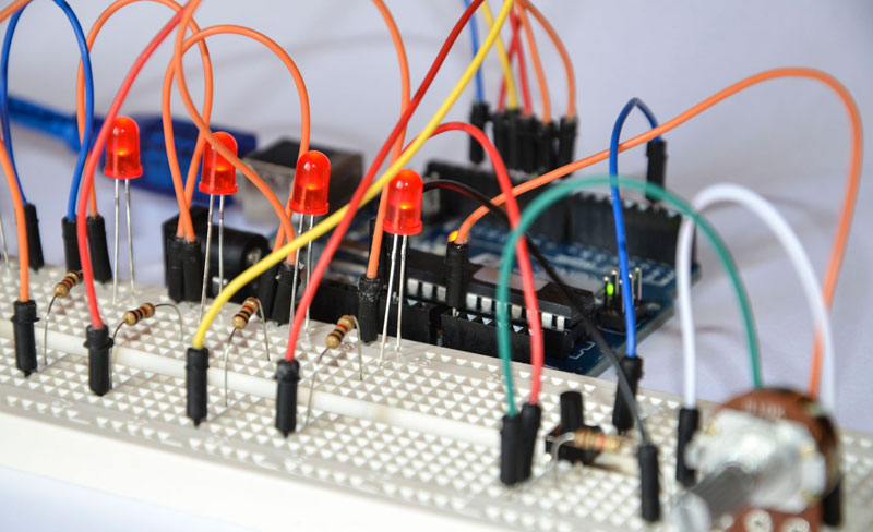
FREE PDF - Simple Arduino Uno projects for beginners tutorial. Learn about electronic components, circuits, breadboard and programming for a Makerspace
I have a question
I hope it is Arduino related enough
I built a LED matrix, using SMD leds
And used 2n2222 transistors
Of course, this is only a prototype
I want to build a small Li-Po powered watch
And I want to use SMD transistors
Can someone recommend me a NPN or N-gate SMD transistor that works well enough for this kind of job?
THT is way too bulky for my specific project
The LEDs I use are simple SMD red LEDs with a forward current of 20mA and a forward voltage of about 2.2V. So nothing special
Thanks in advance! 😄
 west stream
Does anyone encounter an empty serial monitor while the sketch has been uploaded? Because this is my first time facing this current problem 
north stream
@signal lantern You can just use a SMT version of the 2N2222 such as an MMBT2222A, or a little MOSFET like a 2N7002.
@west stream I've seen various things cause issues with the serial monitor. Older versions of Arduino would loose the serial monitor connection when the sketch was uploaded, and you'd have to close and re-open the serial monitor. That has been largely fixed. Some boards have odd issues with sequencing, so you have to check that the serial port is ready (or have a short delay) before you can send to it.
signal lantern
Oh, MMBT2222A is exactly the transistor that caught my attention, but I did not know it was actually a 2n2222 in a different package. I am still a beginner at circuit design. Thank you very much!
 strange ether
@signal lantern thanks
signal lantern
Hmmm. I have another question
Is there any IC
That charges a Li-Po cell from 5v and protects from over-discharge?
I have some small boards that allow you to charge a battery
But I want to make it fully integrated
north stream
Yes, there are many, such as the MCP73831 used in https://www.adafruit.com/product/1904
signal lantern
Thanks!
west stream
i see, will do! thank you 
 stark hollow
could i use the change mode (in arduino interrupts) to filter through a list?
filter as in a forward button and a backward
north stream
I don't see why not. I'd use the usual mechanism of having the interrupt set a flag, and the program's main loop check the flag and update the list position accordingly.
stark hollow
ahh thanks
 knotty rover
Does anyone know if the Adafruit HUZZAH32 is dead? as of 2017 it was listed as a work in progress, and looking in the arduino ide, it still doesn't have a basic bluetooth spp example I can find
I have a nrf52, and bluefriend le module, thinking they could do spp, but now I understand they can't. I'm trying to find a tiny battery powered with charger module I can use with bluetooth spp profile.
i have a heltec esp32 wifi module with bluetooth that works great, but its a few mm too wide for the enclosure I want to use
so i'm trying to find another platform to switch over to
north stream
I would have guessed that "UART mode" was SPP, but apparently I would have guessed wrong.
knotty rover
as did I 🙂
any other modules I should look at? the problem Is I need a traditional serialport on a pc, so that eliminates btle
i have a sparkfun redboard artemis module as well, its the right size, but their code compared to adafruit libraries are horrid, and its btle, which eliminated it
if the heltec board will survive it, i'm tempted to just dremil off one edge of the board, with its contacts so it'll fit. I don't think any important traces run over there . . . but i'd hate to trash a good board just to fine out. On the other side I'd rather trash a board then spend hours more trying to find another board that can do spp profile
 mortal ferry
Does anyone have experience with a SSD1351 128x128 oled making this annoying high-pitched whining sound?
 lost nest
Is it one of these? https://www.adafruit.com/product/1431

We love our black and white monochrome displays but we also like to dabble with some color now and then. Our big 1.5" color OLED displays are perfect when you need a small display with ...
Usually annoying high-pitched whines are caused by inductors (so called "coil whine") or piezoelectric effects in capacitors (so called "singing capacitor")
You might be able to just touch various components on the board to see if you can damp it out and identify what the source is
 wraith current
@knotty rover i recently bought a huzzah32. bluetooth works fine.
knotty rover
@wraith current thanks, I ordered one earlier today. I found out that what I was missing is that even though heltec had its own arduino esp package in the board list. after setting up the official esp boards manager, I was able to push the code unmodified still to the heltec, but I have another 30 boards I can target with the official lib.
 elder hare
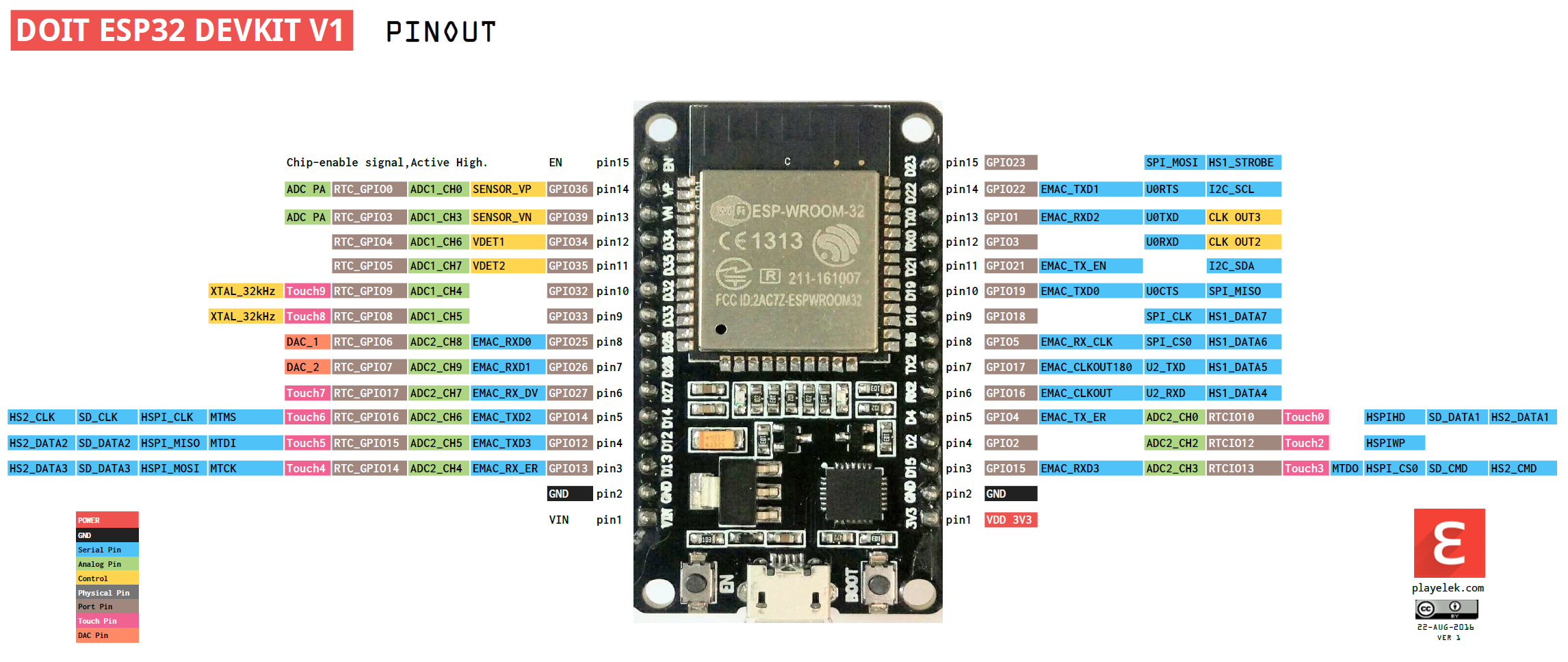
is it ok to have this powered by 5V PSU on VIN and GND and also have the USB hooked up at the same time?
https://raw.githubusercontent.com/playelek/pinout-doit-32devkitv1/master/pinoutDOIT32devkitv1.png
 elder hare
anyone every worked with the sparkfun Spectrum Shield? 🙂
north stream
It does say "the power source is selected automatically" here https://docs.zerynth.com/latest/official/board.zerynth.doit_esp32/docs/index.html but the schematic link https://github.com/SmartArduino/ESP/blob/master/SchematicsforESP32.pdf doesn't work and it doesn't specifically say anything about hooking up two power sources at once.
west stream
Is this a boot error code? Everytime the code was uploaded to the ESP8266 module, the serial monitor always appear this. 🤔
 spice scarab
I've been playing with some Herkulex smart servo motors, which use serial communication to send/receive commands to set position and such, and from what I can tell the TTL voltage is 5v. I've been using an Arduino Uno to control it which works perfectly, but I want to switch it over to my Arduino Nano 33 BLE which can only send/receive 3.3v. For now I'm not worried about whether the motors will actually run at 3.3v, but I am worried about the motors sending 5v back to the Nano 33 and destroying it. I'm thinking about using a voltage divider to bring the 5v down to 3.3v between the TX of the motor and the RX of the Nano 33, but I'm not completely sure of my understanding of serial communication to know if this is a dumb idea or not. Could anyone look at this circuit and tell me if I'm a dummy or not?
north stream
That looks fine to me.
clear fog
Hi Guys, anyone got a skilling hacking things to run then with Arduino?
Been trying to control this board: https://arduino.stackexchange.com/questions/74968/controlling-a-ultrasonic-driver-board-with-arduino

Arduino Stack Exchange
I Have a Ultrasonic driver board that is activated with a momentary switch acting as a toggle (click turns it on - click again turns it off).
As the main chip has no writing on it, how would I pro...
north stream
8 pin chip is some generic microcontroller. Your best bet may be to do without it.
clear fog
@north stream Would it also be doing the 135khz signal generation? or could i just remove it and feed 5v to its output?
Is that round thing on the back doing the signal generation?
what is that called
north stream
It's unclear, there's not enough detail in the pictures to trace things out.
There are 3 main possibilities: 1) the microcontroller is generating the ultrasonic signal and it's just being amplified by the transistors. 2) The transistors are forming an oscillator that generates the signal whenever it's powered. 3) The transistors are using the transducers as part of the oscillator somehow.
When you say "the round thing", do you mean the cylindrical blue component with 3 leads? That is probably an inductor or transformer. It could be used as an oscillator component, for impedance matching to the transducers, a filter, or some combination.
If it's 2 or 3, yes, you could just feed 5V to the right point and it would generate the signal. If it's 1, then you'd have to come up with the drive frequency somehow (might be able to do so with an Arduino).
 tulip mortar
This HX711 is attached to my Feather NRF52840 https://learn.adafruit.com/introducing-the-adafruit-nrf52840-feather?view=all#pinouts
From HX711 --> Feather:
VCC -(yellow)-> 3V
CLK -(orange) -> A0
DOUT -(red) -> A1
GND -(brown)-> GND

Adafruit Learning System
The first Bluefruit Feather with USB and CircuitPython support
#include "HX711.h"

#define DOUT A1
#define CLK A0

HX711 scale;

float calibration_factor = -7050; //-7050 worked for my 440lb max scale setup

void setup()
{
  Serial.begin(9600);
  while (!Serial)
    delay(10); // for nrf52840 with native usb


   scale.begin(DOUT, CLK);
  Serial.println("Started");
}

void loop()
{
  scale.set_scale(390000);

  if (scale.wait_ready_timeout(5000)) {
    Serial.print("Scale: HX711 reading: ");
    Serial.print(scale.get_units(), 1);
  } else {
    Serial.println("Scale: HX711 not found.");
  }
}
I'm getting "HX711 not found" I've been staring at this and trying different pins for the last day. I'm afraid it's not clear to me what I'm missing. Any insight would be appreciated!
cedar mountain
Are you sure that the HX711 library works with the nRF, or do you know if it needs to be put on particular peripheral-capable pins?
tulip mortar
Well, I know that it works, because embarrassingly enough, I had it working awhile back, and somehow lost the code. It's the pins that I'm assuming are wrong. The HX711 says something about digital output, and these are analog pins, But I couldn't find anything in the pinout that suggested what else I should use.
cedar mountain
Ordinarily I'd expect any pin to work for digital peripherals, it's just that analog inputs only work on a subset of them.
 green sable
Hey guys! I'm looking to extend some feather boards on ribbon cables... so I need 12 pin and 16 pin single row IDC style headers along with some ribbon cable. Digikey has a data sheet for this at https://media.digikey.com/pdf/Data Sheets/AVX PDFs/8284_Series.pdf but it seems liek they don't stock the part. Anyone have a similar source or another solution?
lost nest
@green sable Samtec will make pretty much anything you like, but it will have a 23 day lead time (normally 7-day, but they're back-ordered a lot due to current events)
 rough torrent
how come the Adafruit Arcada docs for the PyGamer don't work?
https://learn.adafruit.com/adafruit-pygamer/arcada-library

Adafruit Learning System
Fits in your pocket, is fully Open Source, and can run CircuitPython, MakeCode Arcade or Arduino games you write yourself!
The one for the PyBadge works though
https://adafruit.github.io/Adafruit_Arcada/html/class_adafruit___arcada___s_p_i_t_f_t.html
 left sand
I am trying to operate NeoPixels with the micro:bit using Yotta. I have used this library here (https://github.com/elmorg/uBit_neopixel), slighly modified to be able to be used on all pins.
However, I am running into some issues. The first time I call show(), the NeoPixels light up as they are supposed to. But for the second update, all LEDs light up yellow. Then on the third, everything is OK again. On the fourth, all yellow.
If anyone have any suggestions, it would be greatly appreciated!
knotty rover
when new electronics come from a factory and have the white glue where the wires meet the pcb to help strengthen the connection what is that glue called?
 azure isle
One issue I have encountered with the Arduino system: Suppose I have some compiled code for which I do not have C/C++ source code. How could I incorporate it into an arduino project?
(Note that I do have the source code, but it's in Rust, which is not supported by the Arduino ide/cli.)
lost nest
It looks like Arduino now supports precompiled libraries
Arduino Command Line Interface
 gilded jay
class WifiManager {

  public:
    void setupWiFi(void (*manageDisconnectionFunction)(), void (*manageHardwareButton)(), Adafruit_SSD1306 display);
    void setupOTAUpload();

};```guys I have a class like this
as you can see I would like to pass the Adafruit_SSD1306 display as parameter to the setupWiFi function
I setup and instantiate my display variable inside my setup() function
but when I try to pass that variable to the setupWifi function
I have a stacktrace with an error
any idea of why?
please quote me if you answer me
lost nest
@gilded jay I think you want to make that a pass by reference if you want to declare it elsewhere and then pass it in.
So Adafruit_SSD1306 &display
gilded jay
@lost nest thanks for the answer. I tried
Adafruit_SSD1306& display
before and same results
I don't think that it's because I put the & in a wrong position right?
lost nest
I don't think so. Do you have a compile error, or a runtime error?
gilded jay
Runtime
lost nest
How do you get a stacktrace at runtime off an arduino?
lost nest
Debug logs
gilded jay
Using esp8266 with Arduino SDK
lost nest
Can you paste that log somewhere and link it?
gilded jay
It crashes and loop
I'm not at the computer now. I will try to post that logs tomorrow. I really appreciate your help.
This is the output
@lost nest
load 0x4010f000, len 1384, room 16
tail 8
chksum 0x2d
csum 0x2d
v645464ca
~ld
 frank salmon
I am struggling with coding an SPI connection to a sensor device. I am successful at reading the device's revision ID. Initially I was using the SPI lib from Arduino but changed to the Adafruit BusIO library and it looks promising ... but not quite. I am running into many brick walls now. Help?!
The device is an RM3100 so there's no pre-existing library except in the mbed environment ... which I can't directly use.
cedar mountain
Ah, neat, that's a cool sensor. 😁
frank salmon
@cedar mountain I hope so! I haven't gotten a single reading off it. I always get 0,0,0
doing something wrong but can't see what is the issue.
SPI is not as nice as I2C 😕
cedar mountain
Are you able to read the REVID register to make sure the SPI bus is working?
frank salmon
Yes, I believe that I have the correct return value - 0x22
I'm using SPI mode 0
so next I am confirming the BIST
Says to set 0b1---1111 for register 0x33
cedar mountain
Cool. So then it's probably just something wrong with the measurement sequence... setting the cycle count, etc. Are you following the example in the manual?
frank salmon
Yes the one for the Built in self test. And yes, I agree probably something really nit-picky that I am not seeing.
I'll try just a measurement for kicks.
I'll release this on github once done
correction ... once working enough 😉
The Adafruit BusIO library makes this work a lot easier - I'm really pleased/thankful
cedar mountain
(And yes, it does look like 0x22 is correct for the REVID, so you've got the basics working.)
frank salmon
Thank you for that @terse raptorKeys - makes me feel a lot better about my results so far.
I think my device must be fried. Gonna contact the vendor tomorrow. Thanks EdKeys
livid holly
Oh wow. That does look like a nifty sensor if it truly is a more accurate compass. I found and looked at the user manual. That SPI timing diagram looks nuts. Good luck @frank salmon
frank salmon
@livid holly - thanks for the encouragement. For those who are curious about magnetometers check this link where a UK physicist discusses the RM3100 extensively. https://www.liverpool.ac.uk/~cmi/mag/magChip.html
And then I just found this about a proton precession magnetometer which is really accurate ... http://geekysuavo.github.io/ppm/
cedar mountain
Thanks! When I did a survey previously, the best "normal" magnetometer chip looked to be ST's LIS2MDL. I'm not sure if that's still the case, as it was done a few years ago.
frank salmon
I have a mlx90393 that's next on the list to try. It has a wide range of field strength 5-50mT ... not sure about accuracy etc. I'm going to find out soon though. 🙂
Meh - maybe not.
lost nest
@gilded jay Are you starting from working software and adding this display is the thing that causes the problem? I'd definitely advise starting with a minimum known working set of SW and working up slowly from there
 glad folio
im using a dht11 humidity/temp sensor, but when i have it hooked up it is displaying Humidity: 255% and Temp: 255C. Any idea why?
lost nest
Somewhere in your data collection/signal processing/printing chain, the data is getting clipped, likely to the max of an 8-bit unsigned integer. That seems like a strange data type for temperature/humidity (I'd expect a float) so that might be something to investigate first.
Also, make sure that you have the recommended 10K pull-up resistor to 3.3V on the DATA line
glad folio
@lost nest its is a 3 pin module with a built in resistor
lost nest
It seems from the tutorials that some of the parts in the series have the pull-up resistor, and some do not
and that the DHT11 appears to not
(and when Adafruit sells the part, it comes with a resistor included in the kit)
pine bramble
hello
gilded jay
@lost nest
I have a lot of things that uses the displays. Problems started when I switched from Arduino to platformio and tried to create a single library that manages all the common parts for the various projects.
frank salmon
@terse raptorKeys I don't know what happened and I don't think I made any major changes to the code - it's working this morning! (As you know the Arduino IDE is limited so I can't backtrack my last few edits to see what I did)
green sable
@lost nest thanks! I actually spent the weekend laying out a board for the feather spec that will use standard dual row IDC connectors to let me daisy chain feathers with a single ribbon cable. I'll probably do a small run of them... I'd be curious if anyone else has done something similar.
 scenic citrus
I’ve been working on my first project using a MCU (ATTiny 84) without a dev board like Arduino or feather. It’s just a basic countdown timer with a display + RGB LED to act as the alarm. I drew up a schematic/wiring diagram - curious to know from those who’ve done something like this before, if I’m missing anything crucial or if there are any obvious improvements to be made? Thanks in advance
The [15:00] is a 7-seg display module with built-in TM1637 driver & 2-wire interface. Wasn't sure how best to keep power from flowing backwards to the 5V boost circuit when I have the ICSP header plugged in for programming, so I included a physical switch for now.
I put a 10uF cap across the power leads near ^that switch and a .1uF cap across the ATTiny's VCC/GND leads, hopefully those are reasonable + not sure if there are other places i should put them?
north stream
If your display board doesn't have I2C pull-up resistors, you'll have to add then in your circuitry.
Note that the LED connected to the MOSI line might interfere with ISP programming.
Looks pretty solid overall.
rough torrent
Hey, is it possible to use Adafruit_SPIFlash and Adafruit_Arcada in the same sketch? I'm getting Error compiling for board Adafruit PyGamer M4 Express (SAMD51). when I define
Adafruit_FlashTransport_QSPI flashTransport(PIN_QSPI_SCK, PIN_QSPI_CS, PIN_QSPI_IO0, PIN_QSPI_IO1, PIN_QSPI_IO2, PIN_QSPI_IO3);
Adafruit_SPIFlash flash(&flashTransport);
FatFileSystem fatfs;
in the same sketch with Arcada
The example sketches for Arcada and SdFat work by themseleves
I want to read and write text files with an Arcada interface
So I poked around in the examples menu (I have so many libraries installed it's stupid) and found the Adafruit_SPIFlash libraries
scenic citrus
Thanks @north stream. I had the same concern re: sharing MOSI with an LED pin... it seems to work fine on a breadboard but maybe i shouldn't rely on it. Assuming I have to share one LED pin with one of my ICSP pins [MOSI, MISO, or SCK], are any of those 3 preferred - ie. less susceptible to interference from having a LED on the same pin? Not sure there is an easy way to isolate them
north stream
Easy way is to have the pin drive a MOSFET that drives the LED, but that is an additional part.
Whichever pin the AVR drives would be the logical candidate for the LED, and it may well be MOSI if the AVR is the master during SPI programming (I don't know if it's the master or slave then)
scenic citrus
thanks @north stream - that makes sense. I think i'll just go for it rather than adding a MOSFET since it seems to work ok with my setup, but good to know for next time. Will do a bit of reading on MOSI vs. MISO during programming.
spice scarab
Does anyone know of a web tool that lets you create Arduino tone melodies?
 wanton mirage
Having trouble to getting serial.print to output a readable negative value
-1 becomes 16382
to clarify, it's an expression that evaluates to between -128 and 127 and displays incorrectly when it should be negative.
e.g. Serial.print(xHueDelta32 / 32768);
safe shell
What type is xHueDelta32? See also: https://www.arduino.cc/en/Reference.Arithmetic
wanton mirage
it's an int32_t from the fastled lib
safe shell
Not sure how it handles "32768" if you're on a board with 16-bit int(typically integer constants are treated asint, but you'd think it would handle it appropriately). Does it make any difference if you use32768L or explicitly assign or cast to (signed) long?
wanton mirage
Casting it does not seem to have an effect
but since that input type is non-standard I guess I'm not surprised. I guess I should do my math separately into a container
safe shell
If you don't expect integer answers (seems unlikely), what about 32768.0
(and assuming xHueDelta32 is always within ±4 million and change)
wanton mirage
adding the .0 does change the output but doesn;t fix the wraparound problem. I trried doing the math into a variable and then printing the variable and got the same result as the original
I think I have to cast it into a string or char
safe shell
I don't know what to make of that int32_t typedef, and how Arduino compiler handles it. Arduino rules for types and division are pretty clear, but... ?
wanton mirage
anecdata, thanks for your thoughts. This is a really minor issue at the moment.
safe shell
I'm curious what you end up finding out
north stream
From inttypes.h: ```c
typedef int32_t int_farptr_t;
I think that's the other way around, isn't it, a definition of the farptr type?
 potent ferry
Hi guys. I have six of these boards nRF52840
Do you have any Arduino Bluetooth sample code for using six of these boards in a peer to peer network setup?
Thanks!
clear fog
Hi Guys, I was if i can program a Pro Mini 05 ATmega328 with a USBTinyISP Programmer

Description: 100% brand new and high quality USBtinyISP is designed for AVR, based on USB connector’s ISP downloader. Officially supported by Arduino IDE and compatible usbtinyisp, we can burn Arduino bootloader onto chips, and practically program any Atmel AVR microcontroller...

Core Electronics
It’s blue! It’s thin! It’s the Pro Mini! This is a 5V board running the 16MHz bootloader. Pro Mini does not come with connectors populated so that you can solder in any connector or wire with any orientation you need
 noble fjord
got question i am working making a loop antenna controller using a steeper motor but i want to controll it with a ir remote is any idea how to use it with arduino uno stepper motor and stepper driver and ir modual
north stream
Yes, you can run a stepper motor with a driver board, and use an IR receiver and an IR library to get commands, then your code could control the motor based on the IR commands.
wraith current
RE Huzzah32 featherboard. I'm wondering which ADC channel the battery sense pin is on because I really would like to be able to measure the battery while still using the wifi
Note you can only read analog inputs on ADC #1 once WiFi has started```Nevermind, think I found the answer, it's on channel1
 calm crown
how do you write a for loop with sensor, like, if the sensor is <5 cm away from object, let a led burn
safe shell
ESP32 fwiw... ADC1 pins on the ESP32 are: 36,37,38,39,32,33,34,35 (in channel order). 37 & 38 are not exposed on the Adafruit Feather Huzzah or Huzzah Breakout. 36 & 39 are the Hall Effect Sensor. 32 & 34 are best for general purpose analog input (33 also unless the ESP32 is running the NINA firmware, in which case it's used for SPI). 35 as you found is 1/2 battery voltage on the Feather (but it's available for general purpose analog input on the Breakout).
north stream
@calm crown Something like ```c
void loop()
{
if (sensor.distance < 5) {
digitalWrite(LED_PIN, HIGH);
} else {
digitalWrite(LED_PIN, LOW);
}
}

 north stream
I didn't know what sensor you were using, how it was read, or what units were returned, so I just put in sensor.distance as a placeholder to illustrate the flow.
 slow rapids
Hello! I'm experimenting with an ESP8266 together with a MAX31855 to push messages to an MQTT server. Is it possible to run two "serial" communications on one chip or does that make the complexity go up a notch?
slow rapids
Oh snap, it works now. I love you all.
noble fjord
ok i just need to be able to figure out code for the ir commands then @north stream
not good at coding for adruino @north stream
north stream
There's a tutorial on using an IR library at https://learn.adafruit.com/using-an-infrared-library that might help but there will be a certain amount of coding you'll still have to do to implement whatever logic you need to control the motor in response to IR signals.
Fortunately, the libraries do most of the heavy lifting for you, so your logic will just be something like "When the forward code is received, turn the motor on in the forward direction"
noble fjord
i am thinking about using brainy bits code for it
@north stream

TUTORIAL
Control a Stepper Motor using an IR Remote and an Arduino
OVERVIEW
Here's a fun and easy way to control a Stepper motor at a distance using an IR Remote control.
The stepper we are using comes with its own driver
north stream
That code looks like a good starting point: you'd just have to figure out what codes you get from your remote control if they're not the same as the one in that example.
noble fjord
DO you know if the uln2003 stepper motor driver board would work with the nema 17 stepper motor @north stream
north stream
The NEMA 17 is a size description, not a power description. The ULN2003 is good for up to 0.5 amps and 50 volts. If your motor will run within those limits, it should be fine.
north stream
While you can run steppers on lower than rated current with less torque, that's a good bit less: you might want a beefier driver for those motors.
noble fjord
i just cant find a smaller board to controll it
will a h brige drive controller work @north stream
north stream
Yes, H bridge controllers are a popular choice for stepper motors.
The L298N chip is one reasonable choice, and there are several chips like the TB6612 designed for driving steppers.
north stream
It depends on what you have available, what you're trying to do, and what you're comfortable with.
 restive acorn
Hey, I'm looking to run 2.5m of SK9822 144 LED/m from an Arduino and was wondering what Ardunio would be suitable.
noble fjord
arduino uno @restive acorn
or the mega @restive acorn
what you going to use it for @restive acorn
restive acorn
I'm looking to create a simple light + animation for my mini fridge
restive acorn
the smaller the better is my thought. Q1 was the board, Q2 is the power 😂
I was thinking about hooking it up to the existing power in the fridge as there's a light already in there
noble fjord
yeah but smaller not always better
restive acorn
but wouldn't know what converter I'd need
noble fjord
well get u a ac buck converter
what voltage does the light in the mini fridge use
@restive acorn
restive acorn
just hunting down the model of the fridge
noble fjord
let me know chaz and i can google a down converter for u
restive acorn
Iconic Coca Cola branding sets this Undercounter Drinks Cooler apart. Enjoy perfect drinks from your own Drinks Cooler. Order yours today!
similar to this
noble fjord
i need you to take a voltage meter and messure what the voltage is the out put of the light
@restive acorn
restive acorn
yeah I definitely don't have one of those lying about
I'll put it on the shopping list
restive acorn
anything else you think I'll need?
 glass hound
Any notes on my units
noble fjord
some wires and clear heat shreank @restive acorn
maybe set of small screw drivers @restive acorn
restive acorn
And another quick question, is there a simple on off gate when two contacts are touching? ie fridge open and closed
noble fjord
when u can tell me what voltage is being put into the light then i can tell u what step down deal to get
restive acorn
thanks @noble fjord, this is the most help I've got out of a discord channel!
noble fjord
you can use a the same thing a 3d printer to limited pos switch @restive acorn
glass hound
My led strip
i think they are white i cant remember.. they have 2 wires so.
how do i gat them to run with out a modulater
i just need them to turn on and not be bright
very dim
 dusk summit
Hi guys, I'm an escape room designer, and I'm looking to use an arduino to power one of the puzzles. For context, I haven't used an arduino previously, and my electronics experience generally is very limited (previously I've focused on designing mechanical/tactile puzzles). The intent of the puzzle is for players to link up a number of wires between different headphone jacks, and for a laser transmitter module to activate upon them doing so correctly (this will form the basis of their next puzzle). My design so far is as follows:
My question (very basic as it is!), is where on the arduino must I attach the laser transmitter module, so that I can trigger it upon the puzzle being solved?
Ah, I forgot to mention- in regards to the LEDS, they serve only to indicate to the players once a wire is correctly connected. They are not essential to the puzzle functioning.
north stream
It depends a little on how your laser transmitter is powered, but a common setup is to connect a switching transistor to a free GPIO pin and use that to switch the ground pin of the load (in your case, the laser transmitter)
elder hare
   #include <FastLED.h>
   #define FASTLED_ESP8266_RAW_PIN_ORDER

   #define NUM_LEDS_PER_STRIP 199             // NUM LEDS PER STRIP (NLPS)
   #define NUM_STRIP 6                        // NUM STRIPS (NS)
   #define COLOR_ORDER GRB                    // COLOR ORDER
   #define LED_TYPE WS2812B                   // LED TYPE
   #define FRAMES_PER_SECOND  120             // FRAMES PER SECOND (FPS)

   #define PIN D8                             // LED PIN Studio Lights = 15 / D8

   CRGB Strip[NUM_STRIP][NUM_LEDS_PER_STRIP];

   FastLED.addLeds<WS2812B, PIN, GRB>(Strip[0], NUM_LEDS_PER_STRIP).setCorrection(TypicalLEDStrip);
why do i get this error
 north stream
"Invalid pin specified"? Might mean you specified an invalid pin. It looks like the library is looking for an hardware SPI pin and there aren't any.
elder hare
as you can see in the comment on PIN i've used D8 and 15 but none of them work :S
north stream
You'll have to choose a pin that works, I suppose.
elder hare
the pin works :S
it's the pin im using right now on my ESP8266 :S im just cleaning up my code
omg
....
i had to change the order from
   #include <FastLED.h>
   #define FASTLED_ESP8266_RAW_PIN_ORDER
to this
   #define FASTLED_ESP8266_RAW_PIN_ORDER
   #include <FastLED.h>
Ah yes, good catch. I totally missed that too.
 dense valve
FYI, there might be a difference in output buffering on nrf52840 boards in Arduino code: https://forums.adafruit.com/viewtopic.php?f=65&t=164747
 karmic stream
do all interrupts of the ATmega328p set an "interrupt active flag"? I seem only to find a few that use an "Interrupt Flag Register", but not all.
calm crown
@north stream sorry to bother you again, but your function doesn't work, btw, i'm using HC-SR04
i can send screenshot of my code, if that would help you
calm crown
 flint smelt
Hey, is there a way to put the Feather nRF52840 into a low power or sleep mode until an interrupt is triggered?
Or for the Feather M4
cedar mountain
The chips are certainly capable of it. Just a question of library support for your framework.
flint smelt
Just compiling with regular Arduino and Adafruit libraries, etc
glass hound
ca anyone help me with my above project
flint smelt
@glass hound I did something similar but my lights came with a dimmer and I just set the dimmer where I wanted it.
flint smelt
The LED strip I bought came with a 5v power supply and a dimmer, all connecting with barrel jacks
I bet you could create a PWM signal with a 555 timer and a transistor (as well as some resisters and caps to set the duty cycle)
 woven mica
@calm crown you use the pinMode wrong. It has to be pinMode(red, OUTPUT);.
And you dont reset the red LED to LOW if the distance is > 10. Same for the red_1. So you eould end with both lit up.
 winter furnace
Hey y'all; I'm in a bit over my head with this and I can't seem to find much on google. I'm using the 8266 arduino core to host a discord bot. To do this I need to hold open the discord websocket at the same time i'm sending data to their REST api, both on 443, but if I have one WifiClientSecure connected to something on 443, the other connection fails.
On a computer with bsd style ports, I think the network stack would normally establish a connection originating at two different local ports
but trying to figure out how that applies to the esp network stack isn't getting me very far on google. I haven't gotten quite to the point of putting together a minimal reproduction and trying to fix that yet, but if anyone could point me in the right direction if I'm barking up the wrong tree, I would really appreciate it!
the esp can service more than one client simultaneously as a server, so i'm pretty sure it's possible
i have my project working now by killing the websocket connection every time I want to issue a command and then resuming it, but feelsbadman
glass hound
do you guys know any tutorials with an led strip that only has 2 wires
north stream
Those normally only need power of the appropriate voltage to light.
north stream
You can control it with an Arduino by using a switching transistor
You would need a source of 12 (or so, it's not critical) volts. https://learn.adafruit.com/adafruit-arduino-lesson-13-dc-motors/transistors
north stream
Yes, you can probably plug it into your Arduino which will regulate it down to 5V for its own use and make the 12V available at the Vin pin. Alternatively, you could power the Arduino some other way (like via USB) and just use that supply to power the LED strip.
north stream
No, USB is 5V
glass hound
Also i can get this to work with the yellow and red
north stream
The transistor is to allow the small amount of current an Arduino can safely provide, to control the larger amount of current (and voltage) the LED strip uses.
That looks like a PIR sensor. Do you mean the yellow and red wires from the PIR sensor, or yellow and red LEDs or something else? I'm confused.
glass hound
wires i dont know what the 2 blue ones are for
what transistor is best for this
and i forgot how to identify them so i guess ill google it
and what resistor would i need
north stream
You have a few choices. You can use a MOSFET like https://www.adafruit.com/product/355 and don't really need a resistor.
Or you can use a bipolar transistor like https://www.adafruit.com/product/976 with maybe a 1k base current limiting resistor.
It depends somewhat on your preferences and the characteristics of your LED strip.
north stream
That's a 200V 9A N-channel MOSFET, it would probably do the job nicely.
Gate threshold voltage is 4V max, so an Arduino should be able to control it effectively.
glass hound
this is what i have so far
save to plug in.. lol
what is a good template for this in the IDE
livid holly
@calm crown I am not sure what is in the sonar library, but they are simple devices. You could try this too https://create.arduino.cc/projecthub/Isaac100/getting-started-with-the-hc-sr04-ultrasonic-sensor-036380

Arduino Project Hub
A basic introduction to the low cost and accurate HC-SR04! By Isaac100.
I used code similar to that when I played with them.
glass hound
what am i missing from the diagram above
 cyan citrus
hey guys how's the pwm frequency on the adafruit feather M0 (https://learn.adafruit.com/adafruit-feather-m0-radio-with-rfm69-packet-radio/overview)
I'm trying to use it for a fan that uses 25kHz for its speed control
I've found someone who figured out how to use an arduino uno on a fan requiring 25kHz but I'm not sure if I need to adjust it for the feather M0
https://forum.arduino.cc/index.php?topic=415167.0
Thx for any help!!
Controlling 4pin fan with PWM 25Khz
 karmic rose
Hi guys, could someone help me with the JS library (Johnny five), to control the arduino ?
 onyx edge
I plan using following tutorial as example - https://www.hackster.io/mjrobot/iot-made-simple-monitoring-multiple-sensors-db887f , the tutorial mentions I should " Use a 4.7K ohms resistor between VCC (3.3V) and Data (D4)" - my question is - why ? 🙂

Hackster.io
Collecting multiple data from multiple sensors connected to the same 1-wire bus and monitoring them from the internet with Blynk. By MJRoBot.
what is it's purpose
pine bramble
The resistor holds the data bus high or in a "I'm not talking" state so other devices on the data bus know they can send data. Per the spec sheet, a 480uS low pulse signals that a device on the data bus has data to send. See page 10 of the spec sheet.
https://datasheets.maximintegrated.com/en/ds/DS18B20.pdf
Enjoy!
onyx edge
The resistor holds the data bus high or in a "I'm not talking" state so other devices on the data bus know they can send data. Per the spec sheet, a 480uS low pulse signals that a device on the data bus has data to send. See page 10 of the spec sheet.
https://datasheets.maximintegrated.com/en/ds/DS18B20.pdf
Enjoy!
@pine bramble thank you. any insights if I can pull anything similar off with simple moisture sensors? generally speaking they have digital output too although majority of tutorials mention only analog output
pine bramble
Digital output and data output are often different things. Interfacing will depend on the specific device you use.
onyx edge
one solution I came across, but it requires diodes which I don't have 😦
pine bramble
Sure, that is an excellent example of using analog inputs instead of data inputs.
north stream
That's more of a multiplexor, probably not what you need unless you're running out of I/O pins.
onyx edge
Have seen multiplexer mentioned too somewhere, perhaps I have some IC that supports that..
Perhaps any of those could be used as multiplexer?(there's no 4051)
north stream
The 4066 can be used as a multiplexor
onyx edge
I'm failing to read digital output of moisture sensor 😦
here's my code: https://pastebin.com/jTBSPC17
onyx edge
I figured the power was off :/
 sinful mountain
I like that the Adafruit HUZZAH32 – ESP32 Feather Board has WiFi & BLE, but the caveats listed (in 2017) sound like the library support isn't there yet. Are these things all still true? And am I correct, this is an Arduino only board, no CircuitPython?
"As of this writing, May 2017, the ESP32 Bluetooth core is still under development and there's only one basic beacon example for use with the Arduino IDE core. So we put this one at the bottom of the list. You can check the ESP32 Arduino core and what has been added here, if there's an example for what you want to do, then you're in luck!"
https://learn.adafruit.com/adafruit-feather/bluetooth-feathers#esp32-feather-8-17
 pine bramble
@sinful mountain It's probably true, iirc.
sinful mountain
Thanks @pine bramble
pine bramble
I think it has something to do with loading code or bootstrapping.
circuitpython should list which boards it supports in its README.md
Espruino WiFi and Espruino Nano seem to be supported, and NRF52 boards are supported.
I don't use any of them; I use SAMD21, SAMD51 and now STM32F405. ;) 8051 in the past.
Supports only SAMD21, SAMD51, nRF52840, CXD56, STM32F4 and i.MX RT ports.
So I think that drives the wooden stake through .. (garbled)
safe shell
garbled?
safe shell
Looks promising that ESP32-S2 will get added to that list
 blissful slate
Can anyone explain NVIC priority on the Feather M4?

GitHub
Atmel Smart ARM devices CMSIS module for Arduino IDE - arduino/ArduinoModule-CMSIS-Atmel
This appears to be what I'm building against
#define __NVIC_PRIO_BITS 2
but the datasheet says there are 3 bits
The more recent version from atmel seems to have it fixed
sinful mountain
Looks promising that ESP32-S2 will get added to that list
@safe shell I watched tannewt working on it in a livestream last week. 😉
safe shell
@sinful mountain I'm hoping for a Feather board eventually. Have you found these BLE and BluetoothSerial examples? https://github.com/espressif/arduino-esp32/tree/master/libraries
glass hound
does anyone know what the 4th wire on my PIR is for i have 2 blue ones
flint smelt
The backlight on the TFT FeatherWing (ILI9341) can only be controlled by soldering the LITE pad to a GPIO, correct?
@glass hound you can never have too many blue wires 😛
@glass hound do you have a model number?
glass hound
just conji
flint smelt
I'm probably not going to be much help without some identifying markings.
flint smelt
The Prop-Maker FeatherWing isn't compatible with the TFT FeatherWing, right?
safe shell
@flint smelt Compatible in what way? Which TFT FeatherWing?
You can cut traces (on the 3.5" and 2.4" TFT FeatherWings) and use other pins for TFT_CS, TFT_DC, RT_CS, and SD_CS. MiniTFT + Joy ...you'd have to switch two pins.
Looks like you'd have to use some of: A1-A4; D4 (on the Feather M4)
Analog pins are given preference in most FeatherWing board designs, it seems, so the digital-only pins on the short side get a little overloaded with certain wing combinations (TFT defaults overlap propmaker and adalogger, for example). The EPD wings use 9 & 10 too, like the bigger TFTs.
 glass vapor
hello can someone help me with a really simple motor driver circuit?
I am kind of a noob when it comes to motors and arduino
this is the circuit (disconnect battery while trying to troubleshoot where I might be wrong).
#include<iostream>
using namespace std;
//define list
int debug;
void setup() {
pinMode(22,OUTPUT);
pinMode(23,OUTPUT);
pinMode(2,OUTPUT);
}
void loop() {
debug=1;
if(debug==0){
digitalWrite(2,HIGH);
digitalWrite(22,HIGH);
digitalWrite(23,LOW);
delay(5000);
digitalWrite(2,LOW);
digitalWrite(22,LOW);
digitalWrite(23,HIGH);
delay(5000);
}
if(debug==1){
digitalWrite(2,LOW);
digitalWrite(22,LOW);
digitalWrite(23,LOW);
}
this is the code (debug is now set to 1 to stop the ports from going high-low-high... etc)
elder hare
how do i access a variable from one class in another? like
// class that has the variable i need access to
class a {
Var_i_need_to_access;
}

// Class that needs the variable from Class a
class b {

}
If you declare it as public you can reference it as an instance member. If it's also static, you can also reference it as a class member.
 opal cipher
having a problem with Bounce2 and STM32duino ..
basically we need this code from the library to catch our board as well
´´´#if defined(ARDUINO_STM_NUCLEO_F103RB) || defined(ARDUINO_GENERIC_STM32F103C)
pinMode(pin, (WiringPinMode)mode);
#else
pinMode(pin, mode);
#endif´´´
where would we find the definitions for boards like ARDUINO_STM_NUCLEO_F103RB ?
then we could just add another case to the library
using an STM32 F407V from the stm32duino boards
we end up with this issue https://github.com/thomasfredericks/Bounce2/issues/49

GitHub
Hello, I try to use the bounce2 under STM32 arduino code and get the following error: .platformio\lib\Bounce2_ID1106\src/Bounce2.h:188:26: error: invalid conversion from 'int' to &a...
okay a workaround seems to be using the boards definitions by STM directly rather than STM32duino
 stable hinge
Hi guys, is there anyone who knows if Pin 7 of the 5V ItsyBitsy 32u4, which is also Interrupt 4, can be used to wake up from sleep mode? It somehow doesn't work in my case while there's no problem with waking up with all the other Interrupts available.
glass hound
does anyone have any sugestions for what my 4th wire is for
north stream
Could be brightness detect, inhibit, configuration, analog output, or probably other stuff.
 south flare
Need help changing a few pin locations for 16x32 LED matrix with Adruino Uno. Digital pins 2 and 3 are used for Red Pin 1 and Green Pin 1 but there is no place in the code to change this. Tried combing through RGBmatrixPanel.h to see if I could change it there but all I found was uint8_t rgbpins[6]; which I am not sure how to modify. Any help with this? Digital pins 11 and 12 are open so how do I switch 2 and 3 to 11 and 12?
cedar mountain
It looks like the pin numbers are provided in the initializer, so it would be changed wherever your program creates the RGBMatrixPanel(1, 2, 3, ...) object.
 glass trail
anyone know how to wrap text with LiquidCrystal?
south flare
If I take the testcolors_16x32 example sketch for instance, the only pins I can define are CLK, OE, LAT, A, B, and C. The pins for R1 R2 B1 B2 G1 and G2 are not defined.
glass trail
sorry @south flare idk what youre talking about
im new
can you simplify it for me? thanks
cedar mountain
Ah, here it is:
static const uint8_t defaultrgbpins[] = { 2,3,4,5,6,7 };
So changing the rgbpins[] values is indeed what you want to do.
cedar mountain
@glass trail , this is about @south flare 's question.
south flare
@cedar mountain I can't find that under RGBmatrixPanel.h Where is that chunk of code?
cedar mountain
This is the right place, but not every question gets answered instantly, depending on who is around and what their knowledge is.
south flare
@cedar mountain ah nvm
cedar mountain
@south flare You shouldn't need to modify the library itself, but I think you can change the values in your own code, like panel.rgbpins[0] = 11;
south flare
@cedar mountain Ok, Ill give that go. Thanks for the help
cedar mountain
@glass trail With a quick look at the library, it doesn't look like LiquidCrystal includes word-wrapping, so you may need to do that yourself in the text that you give it.
glass trail
oh
south flare
@cedar mountain Since matrix.rgbpins is not a member of the RGBmatrixPanel class, I cannot seem to figure out how to change the pins in my sketch and not in the .h file
cedar mountain
Ah, it looks like you can also provide an optional pinlist parameter at the end of the constructor arguments.
No, I take that back, that isn't defined for the Uno.
On AVR, at a quick glance it looks like the use of particular PORT pins is hard-coded because they all have to be on the same GPIO port.
south flare
hhmm, yeah I see what you mean. Should I just add a modifier to the .h file then to allow me to modify the pins through the sketch? Since the ESP32 isn't defined, I still don't see where the 6 RGB pins are defined in the sketch
AH
So no way to get an interrupt for a button working with the matrix running
at least on UNO
cedar mountain
That I don't know, I'm afraid.
south flare
Hhmm ok. Well thanks for the help. Ill go routing around the web and see what else I can find.
onyx edge
Hi, I got trouble turning on moisture sensor via digital output
whenever I connect sensor directly to 5v it works fine, but whenever I try turning it on with digitalWrite(x,HIGH); nothing happens
I'm using arduino nano
plugging into different digital pin solved the problem 😦
onyx edge
I'm trying to read data from moisture sensor on Nano, by activating it via digitalWrite, but the sensor led does not light up(on Comparator) and the analog data I receive is 4 times lower comparing to sensors that are connected directly to Nano's 5V
 cyan jasper
Uhm are you sure 40 mA is enough for moisture sensor?
elder hare
im rewriting my FastLED class and im getting an error her why? (keep in mind im still learning about classes and how they work)
sketch
https://privatebin.net/?7143f64649a9eeca#4w2TaKFWVNASQ98wn6J4Fkt12dw4tURNGayXme2tRduS
error
https://privatebin.net/?a942eec97b4bde12#AnBATCeoyGzJ5Bb6LL5ptDz9ccv2hQN48kSwx6NSMGMc
cedar mountain
(Those links come up as blank for me for some reason.)
cedar mountain
Yep, it does. A static function is associated with the class itself, not a particular instantiated object, so it won't necessarily have constructed any of the class variables.
(Also you have a == versus = issue, but it's not causing this particular error.)
 hollow epoch
is there a shield compatible with this motor?
how do i control this motor with an arduino?
elder hare
@cedar mountain so what i can't have that inside the class?
cyan jasper
Depends on torque and voltage you want to run it at @hollow epoch
That's a weird description for motor though it doesn't specify power
But sth around 5 to 10 amp 12v driver would be good
cedar mountain
@elder hare You just want to remove the static qualifier from Increment(). A static function would be called like MYFASTLED.SETUP(), on the class itself for things which are like universal initialization, whereas for non-static functions, they're called like
myleds.Increment(1);```on a particular instance of the class, which would have a particular array to manipulate.Or alternately you could add static to the ARRAY_STRIP_SETTING declaration so it belongs to the class itself, since this is sort of a singleton instance pattern anyway.
sinful mountain
@sinful mountain I'm hoping for a Feather board eventually. Have you found these BLE and BluetoothSerial examples? https://github.com/espressif/arduino-esp32/tree/master/libraries
@safe shell I have not seen those, but I don't do any Arduino work.
onyx edge
Uhm are you sure 40 mA is enough for moisture sensor?
@cyan jasper Operating Current: 5mA
cyan jasper
IDK i was shooting from hip man
 stark mist
hello, does anyone have a good guide on how to pick an opto coupler and calculate required resistors for interfacing a noisy 12-14v signal to a 3.3v arduino?
cedar mountain
The resistors would want to be in about a 4:13 ratio to bring 14V down to 3.3V. So maybe like 3.9k and 13k from the standard 5% resistor choices.
cyan jasper
@stark mist
I wanted to send link but on mobile Google doesn't play well but you could search reading optocoupler data sheets and vishay has some decent document (pdf) on it
elder hare
@cedar mountain what am i doing wrong here?
sketch (note line 62)
https://privatebin.net/?10d9c9f46b45ad08#3Sjz9YqAsqV5Zoce77JAgLF2Ds78rA1tppyMZyMWTvqy
then in my other file im including this class and trying to do this
MYFASTLED::SetLEDBrightness(doc["Brightness"]);
Error
https://privatebin.net/?4ae6be5eda480a02#FbvA2W14RTsmiiLjDTdT8vxcmbTxWG2YnoxHHZJT4Zng
elder hare
?
cyan jasper
could you try making it equal to a number or 0 in 26th line? @elder hare
lemme know if that works
elder hare
@cyan jasper then i get this
MyFastLED.h:26:34: error: ISO C++ forbids in-class initialization of non-const static member 'MYFASTLED::LEDBrightness'

       static int LEDBrightness = 0;

                                  ^

exit status 1
ISO C++ forbids in-class initialization of non-const static member 'MYFASTLED::LEDBrightness'
Hmm I got nothing sorry🙁
elder hare
thanks anyway :/
elder hare
ok so i fixed the first error
i was told to add
int MYFASTLED::LEDBrightness = 0;
after class definition and it worked 🙂
but now i have another problem as i need todo this for "ARRAY_STRIP_SETTING"
here is the updated sketch
trying to use the function on line 63 outside the class gives errors aswell and im unsure how to fix it :S
static void SetActivePattern (int Pat) { ARRAY_STRIP_SETTING[0].ActivePattern = Pat; }
@north stream you have any clue? 🙂
north stream
@stark mist Optocouplers are fairly easy to use, and there are some logic ones available as well. The input side is basically just an infrared LED, so you'd calculate the resistor similarly to the way you'd do so for an ordinary indicator LED.
@elder hare You need to do what? Yet again, you say "gives errors" and don't tell us what the error messages are: without that information, trying to figure out what's going on involves either installing all the libraries and your code and attempting to build it, or reading all the code and trying to figure out what it's trying to do, what the compiler would do with it, and where that would go off the rails. Either of those is a fair amount of effort.
elder hare
same error as above
this is the sketch
https://privatebin.net/?cd1e3a3a076fc6b8#63Ah8BGhD1fTgyqVgttDkAXg7MQ42ucDj4F7cT6XUgA9
trying to use the function outside the class
MYFASTLED::SetActivePattern(1);
but get this error
c:/users/mythical force/appdata/local/arduino15/packages/esp8266/tools/xtensa-lx106-elf-gcc/2.5.0-3-20ed2b9/bin/../lib/gcc/xtensa-lx106-elf/4.8.2/../../../../xtensa-lx106-elf/bin/ld.exe: sketch\Main_Code.ino.cpp.o: in function `ArduinoJson6150_0000010::enable_if<ArduinoJson6150_0000010::IsWriteableString<String>::value, String>::type ArduinoJson6150_0000010::variantAs<String>(ArduinoJson6150_0000010::VariantData const*)':

C:\Users\Mythical Force\Documents\Arduino\libraries\ArduinoJson\src/ArduinoJson/Variant/VariantAsImpl.hpp:40: undefined reference to `MYFASTLED::ARRAY_STRIP_SETTING'

collect2.exe: error: ld returned 1 exit status

exit status 1
Error compiling for board NodeMCU 1.0 (ESP-12E Module).
now trying todo the same as with the LEDBrightness after class defenition
int MYFASTLED::LEDBrightness = 0;
im not sure as to what type to use i've tried
record_type MYFASTLED::ARRAY_STRIP_SETTING[NUM_STRIP];
struct MYFASTLED::ARRAY_STRIP_SETTING[NUM_STRIP];
typedef struct MYFASTLED::ARRAY_STRIP_SETTING[NUM_STRIP];
Hey guys I bought the adafruit music maker shield for arduino, but I ran in some issues while trying to play music out of the audio output. There where simply not one sound. with the headphones it worked perfectly
 fossil sparrow
I am using an Arduino board to "puppet" a controller from a Bionaire window fan and I an having trouble determining the values of the LEDs
Here's what I've figured out so far
The LEDs are connected to a hot anode and a multiplexed cathode
When the LED is on, the cathode gets pulled to ground
When the LED is off, the cathode is left in a floating state
I am trying to detect the state of the LED programmatically
However, I only get garbage inputs
pine bramble
I have no sound output on the adafruit music maker shield for arduino. But only on the ports for speakers the port for the headphones is working could someone help me pls. Maby <@&617066238840930324>
north stream
@elder hare Sounds like you're trying to set a variable you don't have permission to set. Perhaps the class offers a method (a "setter") to do it for you?
@pine bramble So it works with headphones but not the speaker outputs?
pine bramble
jes thats the problem is there maby a problem on the shield or are my speaker just broken?
north stream
@fossil sparrow That's going to happen with multiplexed LEDs, as the data is changing continuously, and is only valid for certain combinations of signals.
fossil sparrow
I understand that the LEDs won't have a consistent output over time
Would I be able to smooth it out somehow
Either by taking a large number of samples and getting the average value, or with some sort of electronics?
The problem is that even the LEDs that are currently off give me noise
Even if the multiplexer is off (it gets disabled with the specific LED bank), certain LEDs give me noise on the input pin, while others give me zeros
All the LEDs are currently off
north stream
You can't really do smoothing, you need to do synchronized sampling. The LEDs are controlled by two separate signals, so just looking at one signal will only give garbage
@pine bramble I'd try some other speakers first. The only way to find out what's really wrong is to systematically narrow it down.
pine bramble
So I tested my speaker and its working perfectly
pine bramble
and I tested it with another speaker wasn't working either
fossil sparrow
I'm honestly considering removing the controller from the controller board and replacing it with something programmable that emits the proper control signals for the relay board
@north stream What do you mean by "two separate signals"?
this is interesting, I increased the sample rate and got this
maybe now I can measure the pulse width
 long silo
HI, I'm new to arduino and I don't know where to start I hope you guy's have tips for me?
fossil sparrow
what do you want to do?
long silo
build stuff
fossil sparrow
do you have any ideas for projects?
long silo
yes just a simple thing
so
whit an IR remote sending a signal and making a led shine
fossil sparrow
There's a brightness button on the thing that throws off the pulse widths ://///
even when the LEDs are off, some of them are still being pulsed (?)
north stream
When you said "hot anode", I assumed you mean "common anode". To light multiplexed LEDs, the controller cycles through the groups by turning on the anodes one at a time while activating the cathodes for the LEDs in that group that are to be lit. Then it turns off those anodes, turns on the next anodes, along with the cathodes for that group.
So you'll see complicated waveforms for both the anode and cathode lines. To determine whether a particular LED is to be lit, you have to sample when both its anode and cathode lines are activated at the same time.
fossil sparrow
I just figured out that I was wrong when I said they were multiplexed
They are not multiplexed, they are PWM-lit
and the different LEDs have different offsets for the PWM
The anodes are just tied to +5V
north stream
But you said you saw activity for LEDs that were off, which seems odd.
fossil sparrow
yeah
this is when LED 1 is on (first line is LED 1)
This is when all of the LEDs are off, except the 7-segment display which I am not touching
north stream
It is easier if they're not multiplexed, because you can use a sampling approach or averaging circuitry to determine if they're on.
fossil sparrow
However, the anode is still hot
north stream
Or peak-hold type circuitry, perhaps.
fossil sparrow
I am planning to integrate this into the case of the window fan, so the less parts the better
north stream
Then an interrupt driven or sampling approach is probably the way to go (I did a little of each in one recent project)
north stream
Good point, that should be useful
fossil sparrow
the problem is that it's impossible to distinguish the pulse width at the lowest brightness setting and when the LEDs are off
I still have no idea how that works
The anode is still tied to +5V
I am also going to start using the internal pullups of the ATMega instead of the external pullups, it should have the same result anyway
north stream
With LEDs connected, you shouldn't need pullups (unless I'm missing something)
Maybe "off" and "minimum brightness" are implemented the same way?
fossil sparrow
No, because you can see the LEDs when they're on minimum brightness, but not when they're off
The LEDs are being disconnected by floating the pin
so it returns garbage as typical for a floating pin
pine bramble
@pine bramble You need speakers with an amplifier (powered speakers) I think for that shield.
You might want to check if you have the version without the 3W amp. PRODUCT ID: 1790
north stream
A floating pin should get pulled to 5V by the LED, same as an off one. I doubt the drivers have active pullups anyway, they're probably open drain.
fossil sparrow
wait no what am I saying
they're being pulled to ground but I was measuring the PWM'd pins with my multimeter
stark mist
@stark mist
I wanted to send link but on mobile Google doesn't play well but you could search reading optocoupler data sheets and vishay has some decent document (pdf) on it
@cyan jasper Thanks will do I was trying to read through the data sheets but there was some nomenclature there I didn't quite understand, this will be very useful thanks
cyan jasper
In future try reading application manual or something similar for that or that type chip. (I used to read ti's ones for fun) @stark mist
stark mist
@cyan jasper thanks again I'm just reading through this now
essentially I have a vehicle power system that is very noisy and I want to read the pulses from the tacho line and count them on my arduino so I can push that to my data logger
a lot of people seemed to use schmitt triggers but I read some posts about people using optocouplers and it seems like a very elegant solution and less components
north stream
@fossil sparrow A multimeter (other than a fancy high crest factor one) will be confused by PWM, but you had printouts of digital reads. In any case, if it's pulled up (doubtful, but possible), it should read 5V. If it's open circuited, it should still read 5V. If it's pulled down, it should read near 0V.
fossil sparrow
This is the cheapest digital multimeter I could find at Fry's so it is definitely confused
It's being pulled down
north stream
There should be a difference between "low brightness" and "off".
north stream
Yes, if you have one available to you, now would be the time to deploy it.
fossil sparrow
I have a Tektronix 2246 sitting somewhere
stark mist
if its a pwm over dc wouldnt a cheap volt meter set to ac show a good value?
I used one a few days back to read my tacho pulse on my motorcycle
it doesnt give pulse widths or anything but you can see the value
stark mist
the variance in pulse width should change that value I think
so on my bike increasing rpm changed the amount of AC volts the volt meter showed
north stream
Depends a lot on how the meter works. Some will average things, some will take whatever the value is at any given instant (which will vary all over the place), some will take the DC component, some will take the AC component, some will take a combination, some will just pay attention to certain harmonics, etc.
 fiery lichen
So is there a reason the seesaw board would be recognized during the blink example and then after powering down usb and plugging it back in, the micro fails to find the seesaw board? The green light is still on and no wires have moved.
Is the seesaw board sensitive to powering down and back up of the micro? I now have Two seesaw boards that fail to be detected after working just fine a minute earlier
safe shell
@fiery lichen Does the Seesaw board get reset when the micro gets reset or power-cycled (is it getting power from the same USB)?
fiery lichen
Yes
I have a big project and I can’t have seesaw boards failing at random. Wish I knew why
north stream
They're I2C, right? You could try a simple soft I2C test program to see what they are and are not doing.
fiery lichen
Isn’t that what the example is?
north stream
No, the example uses a big complicated wrapper library on top of hardware I2C so it's difficult to get any visibility into what's going on at a low level. Just iterating through some I2C signals in software and monitoring what the response is might shed some light on what's happening.
fiery lichen
That’s definitely outside my familiarity zone
I guess that’s why I bought 8 of them just in case :/
New seesaw board with wiring unchanged works fine
north stream
That does make it sound like they're getting zapped somehow
fiery lichen
Hmmmm
If I power it off a wall brick 5v 8a, is there a way to protect circuits from a surge when you first plug it in? Do I need to?
fiery lichen
What about if I supply power to the see saw and other boards from the voltage regulator on the micro vs the usb pin. Would that help protect things at all?
fossil sparrow
@north stream Here's what the PWM signal looks like for an enabled LED at 2/3 brightness. Note the blips at the top and bottom
Looks like with every cycle, the signal briefly (about 10us) goes to 5V, then 0V, then to the intended value.
This is messing with my cycle length detection
north stream
Hmm, that's a much more interesting waveform than I expected. It looks like the LEDs are being controlled by a current regulating driver of some sort.
fossil sparrow
wait, it is multiplexed
sorry about the rotated picture
but the top is the cathode, the bottom is the anode
this is with the LED on
now if I turn the brightness to 2/3
this is the three brightness settings
so you can see that it's just being PWM'd down
and since I can detect when the cathode is off, I can sync my detection to the pulses
so I don't need to measure pulse lengths or anything, I can just basically pattern-match based on the binary input
here's a better look at it
wait
the only measurements here that actually matter are the ones that happen when the cathode is at ground
the cathode is shared across all of the LEDs I'm snooping
so I can just wait until the cathode is at ground and get all the LED states at the same time (???)
oh so that's how it works, the set of LEDs have a common cathode
then the multiplexing circuitry pulls down the cathode for the specific set of LEDs that are currently on
and pulls up the anode for the specific LED in the set
this was definitely a learning experience lmao
so here's all the code I actually need:
int test(int pin) {
  while (digitalRead(pin_row) != LOW) { ; }
  return digitalRead(pin);
}
I added a timeout in case all of the LEDs were off:
int test(int pin) {
  unsigned long int cur_time = millis();
  while (digitalRead(pin_row) != LOW) { if (millis() - cur_time >= 10) return LOW; }
  return digitalRead(pin);
}
It works and now gives perfect results, thank you for the help!
now it's time to make this arduino act as an i2c device so I can talk to it through my esp32 because I can't get a level shifter and this is my only option
i might need to pull out the atmega328p and connect it standalone for space reasons
actually i already have an atmega328p programmed to work standalone, i might just use that
cyan jasper
Have you considered building a level shifter? It's only 1 mosfet and 2 resistors? @fossil sparrow
cyan jasper
Npn transistors?
fossil sparrow
I only have three loose NPN transistors that already are used in one project
cyan jasper
Okay just seems wasteful and feels like adding point of failure
karmic stream
I have got some rather weird behavior with a static array of function pointers on the ATmega328p. when I call the pointed to function, the normal behavior is expected to be that an LED blinks once. some of those functions have the behavior of being called an infinite amount of times. The exact positions of those incorrectly behaving functions in the array are: Index 1 5 18 21 24
This is the particular code that calls the pointed to functions: https://github.com/jxsl13/lpc1768_blinky_example/blob/a07bc577c1c6049e9821a541c3074348974b820e/src/controllers/atmega328p/InterruptVectorTable.cpp#L288. it is being called form the src/main.cpp
 valid lily
hey guys, so I'm writing a program that uses the serial monitor to interact with the user. However, I want to be collecting data at the same time as I'm running the program but without using the serial monitor, any help?
north stream
If "interacting with the user" is one way (providing updates), then you can use TX for that and RX to collect data. However, if you're using both TX and RX for the serial monitor, you'll need to either use softserial or one of the Arduinos with another serial port to collect serial data.
cyan jasper
slightly related isn't uart send ack after every bit
so its kind of not full dublex?
north stream
No, UARTs don't automatically acknowledge (there are other protocols that do, but not asynchronous serial)
pine bramble
Hi
I'm trying to build a 3x3x3 LED cube
I got it to work but 6 of the 27 LEDS are not turning on. I replaced then but no luck 😦 . What should I do?
Please help
north stream
Probably not a driver problem (which would probably affect 9 LEDs at a time) so loose connection?
elder hare
What type should DATA_PIN be to work? :S
      void SETUP(DATA_PIN) {
        FastLED.addLeds<WS2812B, DATA_PIN, GRB>(Strip, NUM_LEDS_PER_STRIP).setCorrection(TypicalLEDStrip);
      }
 eager dune
Hello, can I get help with this. some one sent me this question and I'm not experienced with Arduino
north stream
@elder hare I'm guessing an integer, to specify a pin?
@eager dune Which part are you having trouble with? Have you installed the Arduino software?
eager dune
I'm trying to learing how to write this code
because I am not experinced with C++ or arduino
I'm just learning unity and C#
north stream
If you go to File -> Examples -> Basics -> AnalogReadSerial, there's some example code for writing data to the serial port
elder hare
@north stream i did try int :/ no go
north stream
As ever, saying "no go" doesn't help us help you, you have to tell us HOW it didn't work. I haven't used that library in years and don't know all its ins and outs.
elder hare
i was out shopping! that's why i gave you a short answer!
fossil sparrow
I'm having trouble with i2c
Whenever I send a message to my board, it stops responding

and here's the output I get:
init
init done
as
I don't think your problem is with i2c, I think it's with control flow. Looks like your program does one thing then loops doing nothing forever.
fossil sparrow
@north stream It registers the function receiveEvent as a receive handler for the i2c bus, then loops waiting to receive a message. When it receives one, receiveEvent starts executing, manages to print as, then stops for some reason
north stream
It could be that the event handler is interrupt driven, and that routine is too long to run in an interrupt context. Maybe have it just set a flag, and have loop() poll the flag?
elder hare
@north stream so im back at the computer! so "no go" means this ->
fossil sparrow
@north stream I'll try it, thanks for the suggestion
cedar mountain
It looks like you can't provide the pin number as a function parameter at run-time. It should be like a #define constant instead.
cyan jasper
Setup can't take any parameters. Functions that happen on their own can't take parameters
elder hare
will this work? :S
cedar mountain
What exactly are you trying to accomplish? That seems a bit needlessly convoluted, but everything ends up hard-coded anyway.
elder hare
i have a ESP8266 with 8 strips to 8 diffferent pins 🙂 and i've made a class for the FastLED library with patterns and everything 🙂 and i want to run multiple instances/objects or whatever it's called for each strip, so then i would need to be able to set the PIN
cyan jasper
That works but what's wrong with define DATA_PIN 9 define DataPin 9
That should be more optimised too
Because how compiler works
elder hare
i can only define 1 pin :S
cyan jasper
DataPin1 , DataPin2...
And on constructor you input different definitions which gets encapsulated inside the class
I really think you're overcomplicating this
elder hare
maybe i am but i've never done this befor
cyan jasper
I read the blog of the guy who wrote switch case of one of the first C compiler (can't remember neither guy's name or compiler's name) he tried to optimize it so much that noone else touched switch case again because it was too complicated, and at some point cascaded if s worked faster because ppl kept optimising
elder hare
@cyan jasper how would you do it then?
cyan jasper
Uhm really dumb way (dumb is not bad. Dumb is good) is create 8 different define data pin and clocks
(if possible run every instance with same clock pin)
Or I create an int array and feed numbers to myfastled and inside my fast led constructor construct a fastled
Though 2nd one requires a bit of pointer use
Or not I'm not sure
That could depend how much you want to optimised it too
elder hare
well working and not broken would be nice 😛
karmic stream
I have got some rather weird behavior with a static array of function pointers on the ATmega328p. when I call the pointed to function, the normal behavior is expected to be that an LED blinks once. some of those functions have the behavior of being called an infinite amount of times. The exact positions of those incorrectly behaving functions in the array are:
Index 1 5 18 21 24
This is the particular code that calls the pointed to functions: https://github.com/jxsl13/lpc1768_blinky_example/blob/a07bc577c1c6049e9821a541c3074348974b820e/src/controllers/atmega328p/InterruptVectorTable.cpp#L288. it is being called form the src/main.cpp
In regard to this, after calling the function pointer the controller returns at the incorrect position. the function pointer at that same position in the array is also called in the ISR. but calling the function outside the ISR returns after the function call inside the ISR, seemingly.

second screenshot: where the call happens, first screenshot: after which function call the subroutine call returns.
(commenting out the function call in the ISR actually results in the correct behavior) this is not the wanted solution, tho!
 near delta
Do you know if i can sell product arduino based?
btw can I use for example adafruit libraries in my products?
Any recommendation about where to get CE certifications to launch an IOT product based on Raspberry pi, Arduino or both is possible in Europe?
cyan jasper
(someone is using atmel studio 🙂 )
elder hare
@cyan jasper when you have time could you show me a quick example?
fossil sparrow
It could be that the event handler is interrupt driven, and that routine is too long to run in an interrupt context. Maybe have it just set a flag, and have
loop()poll the flag?
@north stream This worked, thank you!
karmic stream
does anyone know what compiler flags are used by the arduino ide?
cyan jasper
does anyone know what compiler flags are used by the arduino ide?
@karmic stream you can probably extract them from here
https://gcc.gnu.org/onlinedocs/gcc/AVR-Options.html
AVR Options (Using the GNU Compiler Collection (GCC))
karmic stream
thanks
cyan jasper
also this @karmic stream
https://arduino.github.io/arduino-cli/platform-specification/
Arduino Command Line Interface
north stream
You can also check "show verbose output during compilation" in the preferences, and it will put all the commands it uses, complete with options, in the status window, where you can copy/paste them to do whatever you like (I'll do this if I want to modify the options to, say, get an assembly listing).
stark mist
has anyone had experience of integrating the sparkfun gps library into sketch running on the adafruit clue?
Also inside the arduino ide I'm having trouble getting my serial logger window to work
quite often it outputs nothing, although I think this might be something with the Clue board as if I connect realterm I get the same issue
I'm downloading updates now to see if that will help.
I'm a try a different cable
Failed to upgrade target. Error is: Serial port could not be opened on COM3. Reason: Cannot configure port, something went wrong. Original message: OSError(22, 'The semaphore timeout period has expired.', None, 121)
Traceback (most recent call last):
  File "nordicsemi\dfu\dfu_transport_serial.py", line 113, in open
  File "site-packages\serial\serialwin32.py", line 31, in __init__
  File "site-packages\serial\serialutil.py", line 240, in __init__
  File "site-packages\serial\serialwin32.py", line 78, in open
  File "site-packages\serial\serialwin32.py", line 222, in _reconfigure_port
serial.serialutil.SerialException: Cannot configure port, something went wrong. Original message: OSError(22, 'The semaphore timeout period has expired.', None, 121)

During handling of the above exception, another exception occurred:

Traceback (most recent call last):
  File "nordicsemi\__main__.py", line 294, in serial
  File "nordicsemi\dfu\dfu.py", line 235, in dfu_send_images
  File "nordicsemi\dfu\dfu.py", line 157, in _dfu_send_image
  File "nordicsemi\dfu\dfu_transport_serial.py", line 115, in open
nordicsemi.exceptions.NordicSemiException: Serial port could not be opened on COM3. Reason: Cannot configure port, something went wrong. Original message: OSError(22, 'The semaphore timeout period has expired.', None, 121)

Possible causes:
- Selected Bootloader version does not match the one on Bluefruit device.
    Please upgrade the Bootloader or select correct version in Tools->Bootloader.
- Baud rate must be 115200, Flow control must be off.
- Target is not in DFU mode. Ground DFU pin and RESET and release both to enter DFU mode.
Error while setting serial port parameters: 115,200 N 8 1```hmm
anyone have any ideas on this?
stark mist
does anyone know how to put the clue into dfu mode?
nvrm I think I got it
scrap that I dont got it, still getting the same error after updating libraries and board
actually I'm good
its all back working again
Okay I'm back to my previous original issue before I updated the board
const int baudrate = 115200;

void setup()
{
  Serial.begin (baudrate);
  while ( !Serial ) delay(10);

  Serial.println("Serial Echo demo");
  Serial.print("Badurate : ");
  Serial.println(baudrate);
}

void loop()
{
  if ( Serial.available() )
  {
    Serial.write( Serial.read() );
  }
}```this works
but when I plug in my qwiic gps break out board and include its libraries
the board stops responding and doesn't seem to get past opening its own serial port
#include <SparkFun_Ublox_Arduino_Library.h>
SFE_UBLOX_GPS myGPS;

const int baudrate = 115200;
void setup()
{
  Serial.begin (baudrate);
  while ( !Serial ) delay(10);

  Serial.println("Serial Echo demo");
  Serial.print("Badurate : ");
  Serial.println(baudrate);

  if (myGPS.begin() == false)
  {
    Serial.println(F("Ublox GPS not detected at default I2C address."));
  }
}

void loop()
{
  if ( Serial.available() )
  {
    Serial.write( Serial.read() );
  }
}```with the first program but the board plugged in the serial echo works but with the second program the serial echo does not work
commenting out the mygps.begin() call gets it back up and running so its not a library issue specifically but something is causing the clue to die when I try to open the i2c connection
I wrote an i2c scanner so the first run is with the board plugged in and the second is the board unplugged
I2C device found at address 0x1C  !
I2C device found at address 0x21  !
I2C device found at address 0x39  !
I2C device found at address 0x44  !
I2C device found at address 0x6A  !
I2C device found at address 0x77  !
I2C device found at address 0x80  !
I2C device found at address 0x9C  !
I2C device found at address 0xA1  !
I2C device found at address 0xB9  !
I2C device found at address 0xC4  !
I2C device found at address 0xEA  !
I2C device found at address 0xF7  !
done

Serial Echo demo
Badurate : 115200
Scanning...
I2C device found at address 0x1C  !
I2C device found at address 0x39  !
I2C device found at address 0x44  !
I2C device found at address 0x6A  !
I2C device found at address 0x77  !
I2C device found at address 0x80  !
I2C device found at address 0x9C  !
I2C device found at address 0xB9  !
I2C device found at address 0xC4  !
I2C device found at address 0xEA  !
I2C device found at address 0xF7  !
done```which to me suggests that their lib should have begin called with 0xA1 or 0x21
the default I think in their library looks like 0x42
ya
okay this worked I think its on address 0xA1
the echo is working with the board plugged in and the api initialized on 0xA1
yay for rubber ducking
getting nmea sentences correctly
phew
honestly thought I had bricked the clue for a few moments earlier
cedar mountain
That should probably be 0x21. I2C addresses are only 7 bits, so the ones you have which are 0x80 or greater are likely just aliases of the lower numbers because the high bit is dropped when sending to the bus.
stark mist
I was reading somewhere that there is an extended 8 bit range for address more recently, I'll try 0x21 and see if it still works thanks for the heads up
valid lily
anyone here?
 bronze ember

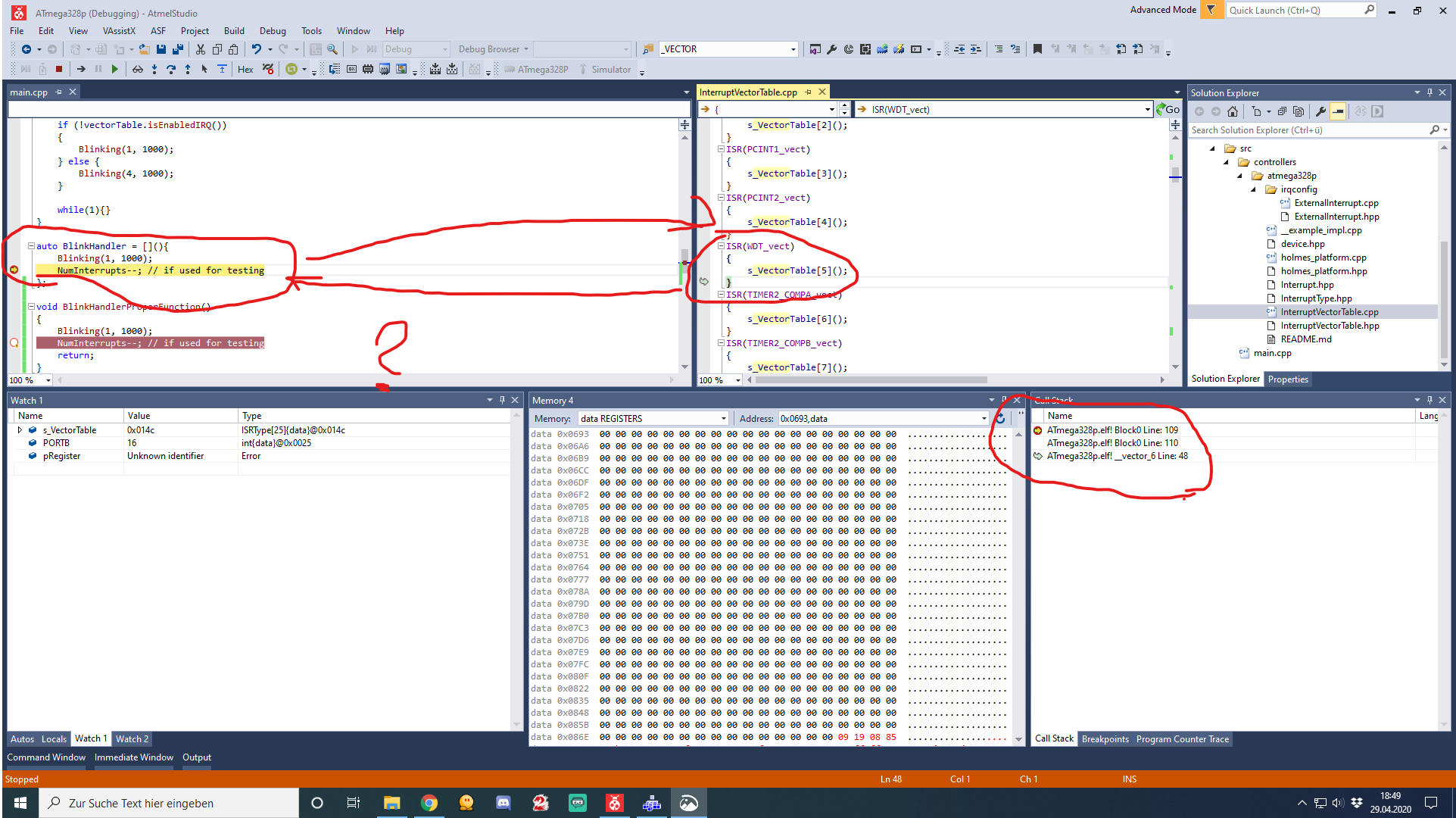
 wild hedge
Is there a way I can get my Arduino Uno to somehow get a message or smth from a webserver run from an ESP32 camera?
cyan jasper
Wired or wirelessly?
flint smelt
I can't get the STM32CubeProgrammer tool downloaded. Once I get logged into st.com the download link disappears. Am I doing something wrong?
Re-registered with a different email address and it works now
Now the software doesn't detect the board but I can see the STM32 BOOTLOADER in the device manager.
karmic stream
atmega328p vs arm cortex-m. it seems that the interrupt behavior is completely different, the avr one, without prior configuration of the interrup source does seem to trigger interrupts directly after the interrupt enable flag has been set. the cortex-m interrupts are seemingly not triggered without any configuration, even when they have been enabled. does anyone have any experience in that regard with those microcontrollers?
cedar mountain
I have some Cortex M experience. Typically there's a distinction between the peripheral generating the interrupt and the NVIC which is dispatching it. So you often have to both tell the peripheral which events should trigger its interrupt output signal, and then enable that interrupt in the NVIC.
cyan jasper
I don't have arm experience but you need some configuration to do for AVR too
Only sei() doesn't cut it
You need to enable interupt source from a register (I don't know if I am remembering this one from Pic but there were two settings one were choosing individual source and one for all external all peripheral etc.)
And you have to set the state iirc from another register (I don't remember actual name)
Optionally enabling internal pull up
But those usually have default values so some people don't bother
(unless there is some sort of different behavior on arm boards but those types of configurations are pretty basic and probably all of the architectures have it)
karmic stream
I am asking more about whether avr triggers interrupts that have their default not configured state by simply enabling interrupts globally and setting the interrupt enable flag of one of the interrupts..
I am kind of simulating an interrupt being triggered with a simple function call. very odd behavior has lead me to assume that like the watchdog(seemingly also visible on the user manual) is directly enabled by setting its interrupt enable flag + sei(). I'm not quite sure, tho, as the controller seemingly does not reset, but infinitely calls the ISR.
cedar mountain
I'm not sure if it's relevant to what you're doing, but I think the AVR architecture has a separate return-from-interrupt instruction, so there may be weird things happening if you call an ISR as a normal function.
karmic stream
I'm not calling an ISR as function 😄 thanks for the info.
I think enabling some interrupts seems to already trigger them.
cyan jasper
without changing global interrupt flag? what are you doing with your code if you dont mind me asking? really curious (I love love register manupilation 🙂 ) @karmic stream
karmic stream
all my code does is simply enable the individual interrupt enable flag, enable interrupts globally and call a function pointer from an array of function pointers that is also called when a specific ISR is triggered.
I had very weird behavior when simply calling a function pointer, which seems not to happen when not enabling the interrupts individually. so I think that enabling interrupts already triggers them.