#help-with-arduino
1 messages · Page 52 of 1
 safe shell
 terse canopy
(clarification, I don't see anything happen until I try sending 2kb of data back)
this is over USB serial
let me send a code snippet and explain what's happening
fft_buffer.clear();

for (int i = 0; i < FFT_LEN; i++) {
    fft_buffer.add(read_uint16_serial());
}

Serial.println("Computing FFT");

arm_rfft_instance_q15 rfft;
uint32_t fft_len_real = FFT_LEN;
uint32_t ifft_flag_r = 0;
uint32_t bit_reverse_flag = 0;
arm_status fft_init_status = reduced_arm_rfft_init_q15(&rfft, fft_len_real, ifft_flag_r, bit_reverse_flag);

arm_rfft_q15(&rfft, fft_buffer.data, fft_results);

write_int16_array_serial(fft_results, FFT_LEN);
so read_uint16_serial and write_int16_array_serial are pretty much what you'd expect
I do my 2kb write
see the Serial.println() call from the above
 surreal pawn
@terse canopy yes, if you want it sent now you should call Serial.flush()
terse canopy
and with my J-Link, I see it hit write_int16_array_serial, dump the 2kb array into Serial.write(), and then keep looping
does it not get automatically sent after some time period?
I set a 10 second timeout on the PC end and got zero data back
surreal pawn
the arduino docs don't say anything about automatically flushing on timeout
you can check the code if you want
terse canopy
I just find it a little ridiculous that my mcu is buffering 2kb of data for serial writes
and not sending any of it over the wire
that seems very wrong
surreal pawn
if you're optimizing for serial throughput it would make sense to buffer as much as possible
terse canopy
that doesn't make sense for a USB 1.1 serial device though
USB specification puts a cap on the packet size
for 1.1, max packet size is 64 bytes
surreal pawn
probably all of the code involved is on github. If you're sufficiently motivated I'm sure you can find out when this decision was made and why
terse canopy
wow, I can't believe it, Serial.write() apparently does buffer even 2kb of data
from a USB packet efficiency standpoint that makes no sense
 pine bramble
It's probably a 64 byte USART type buffer. I'm guessing the Arduino IDE libs buffer outside of that model.
terse canopy
so, actually, I forgot to mention that I'm using the TinyUSB stack
and it seems that TinyUSB also buffers only 64 bytes by default
pine bramble
That's what I'm looking at now. I think. I think they changed a lot of things wrt USB since the last time I looked at this (I'm exploring it via the CircuitPython code base, but my guess is the Arduino IDE support followed a similar path).

 brave cape
Hi people!
So I made this code for my arduino uno that uses an ultrasonic sensor to trigger a light. The ultrasonic sensor works and triggers the light, but when the sensor is not triggered, the light blinks on and off every second. If you think you can help me, please DM me and I can send you the code or photos of the project.
Thanks,
Sketch
brave cape
hi
terse canopy
@pine bramble SAMD21, it's a trinket m0
pine bramble
This one didn't make the last termbin because I didn't let ag run long enough. ;)
ports/atmel-samd/asf4/samd21/usb/class/cdc/device/cdcdf_acm.c:314:int32_t cdcdf_acm_read(uint8_t *buf, uint32_t size)
terse canopy
ah
I'm looking at this right now

GitHub
An open source cross-platform USB stack for embedded system - hathach/tinyusb
going to inspect the tx fifo depth and see if it's something bigger than 64
pine bramble
Yeah I really don't know that code base at all. TinyUSB came in after the last time I looked at this.
The stuff above might very well be the old way of doing it.
(or it may be leveraged by TinyUSB for all I know)
I'll try a broader search as I'm guessing the '64' was kept intact.
terse canopy
I think circuitpython uses TinyUSB now, or at least that's what I'd assume (there's a git submodule for it)
pine bramble
The 64ishness:
https://termbin.com/u1sl
Everything I've stumbled over says control_buffer (however abbreviated) was 64 bytes in length.
terse canopy
(gdb) p _cdcd_itf
$4 = {{itf_num = 0 '\000', ep_notif = 0 '\000', ep_in = 0 '\000', ep_out = 0 '\000', line_state = 0 '\000',
    wanted_char = 255 'ÿ', line_coding = {bit_rate = 9600, stop_bits = 0 '\000', parity = 0 '\000',
      data_bits = 8 '\b'}, rx_ff = {buffer = 0x20002d20 <_cdcd_itf+48> "²\002;\002\210\002Æ\002;\001 ", depth = 256,
      item_size = 1, overwritable = false, count = 0, wr_idx = 0, rd_idx = 0}, tx_ff = {
      buffer = 0x20002e20 <_cdcd_itf+304> "yÿÿ", depth = 256, item_size = 1, overwritable = false, count = 0,
      wr_idx = 0, rd_idx = 0},
    rx_ff_buf = "²\002;\002\210\002Æ\002;\001 \000s\000\000ÿ3ÿOÿAÿ"ÿ\t_\235_AyyOy▌y+ü ûxûSûzûxüSüSû[úDû\016ûöü\220üSûxû-ú¢ú²ú¢úƒúàû[ûkû\036û[ûæü4ûxúÿú¢ûküSüüy:üíü_y▌_P_oyäy:y\033yhy╪üIûöûcûSû\231ûSûxûöü\005ûxûLúÿû\036ûSûxûxûæü¿yä_~_úÿ"\000\000\000M\000S\001\025\002\034\002Z\001I\001\006ÿâÿ(ÿ\000=\000{\000s\000{\000\\\000"...,
    tx_ff_buf = "yÿÿ\000\003\000\nÿoÿ_\000\r\000\022ÿ_\000\001\000\nÿÿÿComputing FFT\r\nÿæ\000\000ÿöÿóÿy\000\002\000\002\000\005ÿy\000\001ÿú\000\004ÿüÿÿ\000\002ÿyÿüÿüÿ_\000\fÿyÿÿÿúÿúÿù\000\003ÿú\000\000ÿûÿy\000\001ÿÿ\000\016\000'ÿ_ÿóÿ_\000\001ÿ÷\000\002ÿ÷ÿÿÿû\000\bÿy\000\000\000\004\000\000\000\006\000\001ÿú\000\003ÿyÿÿÿùÿùÿo\000\001ÿoÿ_ÿyÿÿ\000\aÿ_\000\024\000k\000\006\000\030ÿyÿÿÿÿ\000\004ÿÿÿÿ\000\006ÿùÿü\000\000ÿùÿöÿ"...,
    epout_buf = " Ag{\000\\\000.\000\000ÿ3\000.\001\025\001c\002i\003z\004\n\004\n\004\n\004\n\003û\004)\004+\003û\003p\003\217\003û\004A\005}\005º\005º\005o\005m\005«\006d\006A\006\262",
    epin_buf = "Reality is an illusion\r\n", '\000' <repeats 39 times>}}
this seems to suggest 256 bytes
terse canopy
oh yeah I print that out at startup so I know things are working
pine bramble
@brave cape You'll maybe want to post a gist with all of the code you wrote or borrowed (but not distributed libs; anyone who can help will already have those, probably).
Managing the short serial buffer, whatever it is, is important to most people who have to use the serial port, be it USART or USB.
It's just not something I've studied quite enough, not yet.
terse canopy
as long as I know the behavior, it's not a problem, it's just not very well documented
I noticed wr_idx and rd_idx of the tx buffer were changing, so I'm left wondering where the serial.flush() comes in
pine bramble
The world moves fast and there just isn't enough volunteers to document at that level.
The code itself documents everything but the way the programs are structured, that's a lot of tracing.
terse canopy
I'm maybe guessing that what's happening is, stuff is indeed making it out of the mcu tx buffer and into my PC's rx buffer, and serial.flush() marks the transfer as complete? idk
pine bramble
So you have to get good at tracing from one file to another in the source tree, I guess.
Is there a problem using the flush?
pine bramble
I remember something about it but it's been a while; once I added the flush statement, a particular issue got resolved.
terse canopy
I'm guessing Serial.println() automatically performs a flush and that's why those didn't give me issues, but Serial.write() did
pine bramble
I'm having trouble remembering when and where I used the flush function.
Serial.write(c); is probably data oriented.
terse canopy
oh yeah, definitely
pine bramble
Kind of you to say so. ;) It's hard for me to try to do something and also talk about it. Sometimes when the phone rings I have to .. it's so hard to start speaking again.
brave cape
Hi people!
So I made this code for my arduino uno that uses an ultrasonic sensor to trigger a light. The ultrasonic sensor works and triggers the light, but when the sensor is not triggered, the light blinks on and off every second. If you think you can help me, please DM me and I can send you the code or photos of the project.
Code:
Thanks,
Sketch
oops,
code is here:
// defines pins numbers
const int trigPin = 9;
const int echoPin = 10;
const int led = 2;
// defines variables
long duration;
int distance;
int safetyDistance;
void setup() {
pinMode(trigPin, OUTPUT); // Sets the trigPin as an Output
pinMode(echoPin, INPUT); // Sets the echoPin as an Input
pinMode(led, OUTPUT);
Serial.begin(9600); // Starts the serial communication
}
void loop() {
// Clears the trigPin
digitalWrite(trigPin, LOW);
delayMicroseconds(2);
// Sets the trigPin on HIGH state for 10 micro seconds
digitalWrite(trigPin, HIGH);
delayMicroseconds(10);
digitalWrite(trigPin, LOW);
// Reads the echoPin, returns the sound wave travel time in microseconds
duration = pulseIn(echoPin, HIGH);
// Calculating the distance
//distance= duration*0.034/2;
safetyDistance = distance;
if (safetyDistance <= 10){
digitalWrite(led, HIGH);
}
else{
}
// Prints the distance on the Serial Monitor
Serial.print("Distance: ");
Serial.println(distance);
delay(400);
}
edit:
int trigPin = 9;
int echoPin = 10;
int led = 7;
void setup() {
Serial.begin(9600);
pinMode(led, OUTPUT);
pinMode(trigPin, OUTPUT);
pinMode(echoPin, INPUT);
// put your setup code here, to run once:
}
void loop() {
long duration, distance;
digitalWrite(trigPin,HIGH);
delayMicroseconds(1000);
digitalWrite(trigPin, LOW);
duration=pulseIn(echoPin, HIGH);
distance =(duration/2)/29.1;
Serial.print(distance);
Serial.println("CM");
delay(10);
if((distance<=10))
{
digitalWrite(led, HIGH);
}
else if(distance>10)
{
digitalWrite(led, LOW);
}
}
pine bramble
@terse canopy I found what I was looking for, maybe.
The second one uses both methods.
pine bramble
I could not find extant code where I did use Serial.flush(); but ..
it might be in a branch I'm not checked out on, in one of my local (on-disk) git repositories. ;)
 reef pollen
@north stream I finally got it. You're right (under normal circumstances). Typically during the program the Arduino monitors the serial/usb traffic. If there is a request to program it resets the Arduino back to the bootloader. Disabling interrupts messes with that periodic function and the Arduino can't be reset via the serial port.
Therefore my only window to program is the initial bootloader loop during startup, it was just a small window. I was finally able to reprogram it by wiring up an external reset button, holding it down, and releasing it at the same time the ide tried to upload.
I'm glad I was able to figure it out, and thanks again. You seem to answer a lot of my questions and you mentioning returning to the bootloader is what got me to try this. 🍪 here's a cookie for being so cool. 😄 have a great day!
 unreal finch
ok ive got another weird problem
so im trying to make a leg
heres the code for the IK
and it gives me angles in degree
but once the angle reaches 180 it goes like this
im assuming the angle goes like this:
and then
like this
but i need this angle until 270 degrees
and idk how to because there are gna be 2 same angles like this
^which is the same as the first photo
 north stream
As you see, there are more than one way to get to certain positions, but the mechanism will generally have to "flip" at some point, the trick is to decide when that happens. You've already figured out that you need a particular angle until 270°, so the problem may reduce to explaining that to the code, and possibly making adjustments in the calculations (like "if theta1 is in this range, and theta2 is in this range, subtract pi/2 from theta1 and recalculate").
 loud mural
Is there a place that has the dependencies list for adafruit libraries? I am trying to compile on my raspberry pi but when I was adding libraries I may have missed one or two because it doesn’t show the dependency when I add a library if you catch my meaning. So I need to add the rest of em
north stream
Which libraries? Arduino? Blinka?
north stream
Looks like it depends on SPI, SPITFT, and Adafruit GFX.
pine bramble
🛩️
@terse canopy https://github.com/technoblogy/serpente-core/blob/master/samd/cores/arduino/USB/CDC.cpp#L30
#define CDC_SERIAL_BUFFER_SIZE 256
pine bramble
That turned up when I was using ag to look for Serial.flush() stuff.
terse canopy
problem with hardware debugging is if I spend too long at breakpoints, the USB connection drops out because devices have to poll the bus, which is painful
pine bramble
/some/path/to/technoblogy/0-Distribution.d/ulisp-serpente/ulisp-serpente.ino:1123: if (address == 1) {Serial1.flush(); Serial1.end(); }
Looks like this author wanted to make sure the serial was flushed before closing it entirely.
I also used it ignorantly but haven't looked at the surrounding code.
I'm starting to think something flushes the buffer out the port commonly enough that most use cases won't leverage Serial.flush() unless the intent is to stop using the port for a significant time interval.
wchill: is there any good explanation for why when I make a Serial.write() call on a SAMD board, I don't see the results show up on the other end?
wchill: I'm testing some code so I'm shuffling 2kb of data back and forth over the serial port
Just to recap. ;) (Trinket M0)
 deft frost
@north kelp yesterday you suggested "trade level-of-effort for money, and use a separate board to do your audio signal processing." is there a recommendation for small board that can out of the box have high sampling frequency and process audio data from analog or I2S microphone?
i might have to go with designated audio board because I can't find any software solutions 
surreal pawn
the software solution would be the teensy audio library
[depending on the processing]
 hidden stump
Hey, I've been working on a device im developing with an lcd/w backpack, CAN module and sd card module. I've been having a lot of trouble getting the CAN and sd module to coexist on hardware spi, it's like the sd card was broadcasting on the miso line even when the CS pin was hardcoded high. I ended up putting it on software spi, but have there been ongoing problems with compatibility regarding the sd module by anyone's knowledge?
 floral epoch
Hello
 woven mica
hello
 odd fjord
@fast shard what problem are you having? It's best to just post an example fo the problem so someone can help with it.
 fast shard
I'm Newbie to arduino
Arduino: 1.8.12 (Windows Store 1.8.33.0) (Windows 10), Board: "Arduino Uno"
C:\Users\nimis\OneDrive\Documents\Arduino\sketch_mar06b\sketch_mar06b.ino: In function 'void loop()':
sketch_mar06b:20:9: error: request for member 'read11' in 'dht', which is of non-class type 'DHT()'
 dht.read11(DHT_apin);

     ^~~~~~
sketch_mar06b:20:16: error: 'DHT_apin' was not declared in this scope
 dht.read11(DHT_apin);

            ^~~~~~~~
C:\Users\nimis\OneDrive\Documents\Arduino\sketch_mar06b\sketch_mar06b.ino:20:16: note: suggested alternative: 'dht_apin'
 dht.read11(DHT_apin);

            ^~~~~~~~

            dht_apin
sketch_mar06b:23:22: error: request for member 'readHumidity' in 'dht', which is of non-class type 'DHT()'
 Serial.print(dht.readHumidity);

                  ^~~~~~~~~~~~
sketch_mar06b:26:22: error: request for member 'readTemperature' in 'dht', which is of non-class type 'DHT()'
 Serial.print(dht.readTemperature);

                  ^~~~~~~~~~~~~~~
exit status 1
request for member 'read11' in 'dht', which is of non-class type 'DHT()'
This report would have more information with
"Show verbose output during compilation"
option enabled in File -> Preferences.
odd fjord
post cade between three "backtick" charaters so it gets formatted like this
odd fjord
`
fast shard
10k?
odd fjord
take a look at this guide https://learn.adafruit.com/dht/connecting-to-a-dhtxx-sensor
10K is good
odd fjord
so it compiles OK and loads, but you just get the read errors?
what microcontroller are you using?
if you have a DHT11 then uncomment the #define for DHT11 and comment out the #define from DHT22
//#define DHTTYPE DHT22
What are lock bits used for? Are they important to set? I can't find any info on them. 32u4 if it makes any difference
fast shard
still getting the error @odd fjord
 zinc rampart
Is possible send command speech from Arduino to Google Home?
I need consume data from my API by get method and I need speech on GoogleHome the data receive
Or Arduino > Intermediate > GoogleHome ?
Or Say “Ok google X” and Google response with the data receive from my API?
 nimble garnet
Hi! Anyone know how to make a tft screen update values automatically from Adafruit IO? I've got a few feeds on adafruit that are being monitored by an ESP32 + tft screen, but the values are only updating when i press on the screen. I'd like them to be updated on the screen as soon as they are updated in the feeds. Thanks
ill post the code in a min
nimble garnet

GitHub
My stuff I guess. Contribute to MarcosNiederer/marniesan development by creating an account on GitHub.
line 378 is where im trying to create an "if"command to make the esp32 to update values if the feed is updated. I know this may seem simple but I'm quite inexperienced with this, so anything would help. Thanks
pine bramble
@nimble garnet It's good to see code uploaded on github, as that's a great user interface to it, to cite example lines from a program that's giving you trouble. ;)
So, I would first try to see if I could unconditionally print it (with a delay) and not worry about having it print only when some condition was met, as a first approximation.
When it's printed unconditionally, send a few characters unlikely to appear at any other time, so you can be sure what line of code did the actual printing.
nimble garnet
I can get it to print whenever I press the screen (tft.print "feed value").
pine bramble
I have no idea where you are in 300 plus lines of code. ;)
nimble garnet
sorry, after line 328, in every "if", there's a tft print at the end of it (lines 342, 354,366 and 379)
those print the values each time I press the screen whenever I'm on currentpage"x"
pine bramble
https://github.com/MarcosNiederer/marniesan/blob/master/screen1.ino#L218
for starting the touch screen (so other people will know where this happens)
north stream
@reef pollen the lock bits disable reading code back out once you've uploaded it. They're intended for people who want to protect their code from copying.
pine bramble
This looks like a test for touchscreen input to me:
https://github.com/MarcosNiederer/marniesan/blob/master/screen1.ino#L233
My first question is going to be about balanced delimiters (open curly braces matched with closed curly braces).
Looks like 248 and 265 open and close a large code block.
nimble garnet
248 opens for the first "menu", and it controls transitions between that menu and two others
that's basically "currentpage 0"
line 265 closes that "menu"
pine bramble
Yeah. There's a lot of structure here and I have not worked with this hardware. ;)
The general idea in programming is summarized with the expression:
top down; bottom up; middle out. ;)
So to me top down means the structure.
bottom up usually implies hardware drivers
middle out is connecting the two (structure, hardware).
nimble garnet
yeah that's a good wat to define it
pine bramble
So I am very used to definining empty functions that accept nothing and return nothing, as a kind of placeholder.
When the code gets messy (and near completion!) those empty functions will no longer be empty; the code in them will be near completion, but somewhat (or almost entirely) commented out.
Hard to describe that workflow very well.
nimble garnet
Mhmm, that's a problem I've encountered before
pine bramble
Well there's two primary ways (in C) to remove code from compilation and execution.
You can
/* this is a large block of commented-out code
 *
 *
 */
Or you can use the C preprocessor:
#ifdef NEVER_DEFINED
void foo(void) {
  statement();
}
#endif
The second method preserves syntax highlighting in the code editor.
pine bramble
The editor doesn't know it's dead code so it highlights the syntax correctly.
Ultimately I try to split the code out into separate functions and even to separate files.
The general process is sometimes called 'factoring' the code.
That might be specific to Forth, though, and not something C programmers talk about. ;)
nimble garnet
Yup, so I've got it divided into different "stages" or "void" to express the different menu's and functions. I do not have issues reading it, and I understand it, it's just that I'm a bit stuck with it.
pine bramble
I would also look for substitution of = where you really wanted == as that is super common.
(instead of testing, it got assigned due to a typo)
odd fjord
@fast shard sorry - I had to go out for awhile -- can you post a picture showing how you have the DHT11 wired?
pine bramble
You might be able to simulate touch screen presses, to trigger the same code structure as touching the screen triggers .. on some sort of upstream change from (adafruit.io or what-have-you). @nimble garnet
It looks like 31: int currentpage is a primary control variable, and a global.
So, one may override what is stored in currentpage to fake-out the program into believing foo has happened.
It looks to me (I have never used much of your code before) that you read from adafruit.io once each loop, and store the results of doing so, then test for touchscreen input, and switch to various 'screens' based on that input.
No touchscreen input means that loop was 'wasted' (adafruit.io was read from, but never acted on in any way at all).
So the touchscreen input could be stored in a state variable, and then merely 'consulted' rather than being the main thing driving program flow of execution.
I would remove most of the code (limit to three different events/screens).
Work out the correct program flow to what you want to have happen.
Then add in the other use cases, after overall program flow of execution functions well.
 fiery lichen
Do the Adafruit Hall effect sensors output a variable voltage with respect to how far a magnet it from it or is it more like a trigger device? The description makes me think the output is either 0v or 3.3v with nothing in between. But I’ve seen HES used for distance approximation many times. Do I need a different type to do this?
pine bramble
I think it has to be a rapid event, @fiery lichen
north stream
Yes, the US5881 is a digital, not analog, Hall effect sensor.
pine bramble
fiery lichen
There are analog ones though right?
 raven flame
thrustmaster uses hall effect sensors on their warthog joystick 🙂
very accurate!
so they exist; the question is> do they exist in easy to use pcb mounted thing with i2c lol
fiery lichen
Meh they’re simple. As long as it gives a 0-3.3v output I can convert using an analog input pin 🙂
raven flame
yes but i2c you can read between 2 or 16 of them with just two pins 😄
sorry i am an i2c crazy lady 😄 i love it
pine bramble
@fiery lichen schmitt trigger ;)
pine bramble
I called you 'for dinner'.
When the old mercury bulb thermostat (Honeywell round thermostats were like this) .. encounters a falling temperature ..
.. the bulb reaches a tipping point.
The termostat (very rapidly) transitions from open, to closed switch (SPST) via the blob of mercury.
And then it doesn't want to immediately switch back to the OFF state.
This way, the furnace isn't being turned on and off rapidly (which could start a smokey fire type event).
That's an example of what's called 'hysteresis'.
That hall effect sensor exhibits hysteresis. It's either sharply ON or sharply OFF .. the transitions happen suddenly.
One of the names for this is 'schmitt trigger'.
So, in that plastic package of the hall effect sensor, is a schmitt trigger circuit .. in addition to the sensor itself. This sensor has been 'digitized' by the addition of the schmitt trigger to the basic sensor.
fiery lichen
I need to rip off the Schmitt trigger
pine bramble
It's inside a plastic potting the size of a transistor.
They very likely vend them somewhere without the extra stuff included (just the sensor).
They might even offer both kinds in the same package.
north stream
Yes, there are plenty of analog Hall effect sensors in the Eline style package.
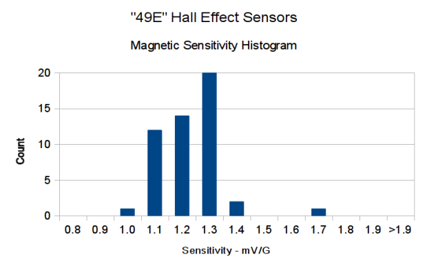
So this lot resembles 49E sensors in both bias and gain.
pine bramble
fiery lichen
@pine bramble can you check your link? When I click it on my phone it says it’s not found
pine bramble
@fiery lichen I'm not sure I found anything new, there. Unfiltered output doesn't seem to be a strong suit for these sensors - they seem to favor interpreted/filtered output. I'm just not sure; I don't use them so I'm just glancing at the literature.
Kind of looks like they are programmed for a specific range (distance, 'D') by LittleFuse!
Like you have to buy them pre-programmed, and are stuck with that one setting.
and they're $14.70 apiece. ;)
nimble garnet
@pine bramble I'll keep what you wrote earlier today in mind, thank you again! sorry for not responding earlier, I was away
pine bramble
@nimble garnet Online stuff is often asynchronous .. for hours, and even days. ;)
nimble garnet
yup, always like that 😉
pine bramble
Can someone hep me with making a self parking car i am trying to make it but i don't work
i wanna use arduino uno
north stream
How far have you gotten? What sort of approach are you taking?
 timber smelt
For a 1602 display
do i need something connected to the buttom of the display so i can connect it to the uno?
 elder hare
https://www.youtube.com/watch?time_continue=648&v=c0tMGlJVmkw&feature=emb_title
this guy says there are fewer librarys on ESP32 then there are on ESP8266 is this correct? :S so if i upgrade there is a chance that one of the libs im using is not supported on ESP32? :S

ESP8266 NodeMCU pinMode Diagram: https://github.com/thehookup/Wireless_MQTT_Doorbell/blob/master/PinModes_ESP8266_NodeMCU.jpg
ESP32 NodeMCU Pin Diagram: https://github.com/thehookup/ESP32_Ceiling_Light/blob/master/PinModes_ESP32_NodeMCU.jpg
Buy an ESP8266 NodeMCU: https://am...
 feral pivot
hi I'm trying made my smart home control panel with an touchscreen arduno mega tft display module .I'm using UTFT Buttons Library but I touched the password but buttond not deleted.Can help me?
Also does anyone know Turkish on this server?
 timid hedge
Does anyone know of a web based application that will allow you to make arduino circuit images?
Like this for example.
Or recommendations I should say.
woven mica
This is made by fritzing, but it is not web based fortunately
timid hedge
Ah. Ok. Thank you!
 cedar mountain
Thanks! I had been curious what all those images were made with as well.
 fervent arrow
#include "SoftwareSerial.h"

//storing the state of the buttons
bool red1 = false;
bool green1 = false;
bool blue1 = false;
bool red2 = false;
bool green2 = false;
bool blue2 = false;
bool relay1 = false;
bool relay2 = false;


#include <ESP8266WiFi.h>
WiFiServer server(80);
IPAddress IP(192, 168, 4, 15);
IPAddress mask = (255, 255, 255, 0);
byte ledPin = 2;
void setup() {
  Serial.begin(9600);
  WiFi.mode(WIFI_AP);
  WiFi.softAP("Wemos_AP", "Wemos_comm");
  WiFi.softAPConfig(IP, IP, mask);
  server.begin();
  pinMode(ledPin, OUTPUT);
  Serial.println();
  Serial.println("accesspoint_bare_01.ino");
  Serial.println("Server started.");
  Serial.print("IP: "); Serial.println(WiFi.softAPIP());
  Serial.print("MAC:"); Serial.println(WiFi.softAPmacAddress());
}
void loop() {
  WiFiClient client = server.available();
  if (!client) {
    return;
  }
  digitalWrite(ledPin, LOW);
  String request = client.readStringUntil('\r');
  Serial.println("********************************");
  Serial.println("From the station: " + request);
  client.flush();
  Serial.print("Byte sent to the station: ");
  Serial.println(client.println(request + "ca" + "\r"));
  digitalWrite(ledPin, HIGH);
  //copy pasting lol
  if(Serial.available()>0){
    String Received = Serial.readString();
    if(int(Received[0]) == 1){
      Serial.println("Red1");
      }
    }
}```Hello, i am using a nextion lcd and I want to recrive some avriables when I press a button. I figured all of the sending the variable to the esp via rx and tx but now i want to make a code that recrives the value 1 and prints red1 but it gives me an error. The other stuff of the code is being used to transmitt the data to another esp(not yet implemented, i want to print to the serial monitor that the esp has recrived the velue 1 from the screen. Here is the error it givem me while I am trying to compile
it is long, had to uplaod it to a txt file
and I am also using electronoob's video for reference: https://www.youtube.com/watch?v=akpF9TbvNss&t=567s
Thanks!
fervent arrow
fixed it by rmoving the nextion libary, hope I won't be eeding it for later
pine bramble
@cedar mountain https://github.com/fritzing/fritzing-app
Have not used this since early 2018.
I can probably install that version as I have a machine that still runs Debian 9.9 (stretch).
Looks like they ported it to 'buster' also.
 simple horizon
Does anyone know how to use the PM5003 on the esp32 feather?
safe shell
More specific question than answered here? https://learn.adafruit.com/pm25-air-quality-sensor
Or is that the wrong thing?
simple horizon
That's what I'm using but the software serial doesn't work because that's for arduino. The hardware serial doesn't work because Serial1 not found
safe shell
Oh, this is Arduino room. You have to set up Serial1 on some pins, like...
Serial1.begin(115200, SERIAL_8N1, 16, 17);
 covert skiff
I'm having a problem with a project, I have a 4 button fan pwm controller that I am making and it works but not completely.
The 4 buttons control the fan at 25, 50, 75, and 100% speed. on setup it should set the output of the pwm to 25% but it is not.
Anyone have any ideas?
#define speedpin1 2 //  push button for 25
#define speedpin2 3 // push button for 50
#define speedpin3 4 //  push button for 75
#define speedpin4 5 // push button for 100
int fansp1,fansp2,fansp3,fansp4;


void setup() {
  pinMode(speedpin1,INPUT_PULLUP);// set pin for push button 25
  pinMode(speedpin2,INPUT_PULLUP);// set pin for push button 50
  pinMode(speedpin3,INPUT_PULLUP);// set pin for push button 75
  pinMode(speedpin4,INPUT_PULLUP);// set pin for push button 100
  analogWrite(fanPin,64);
}


void loop() {

    fansp1 = digitalRead(speedpin1);// read status of button speedpin1
    fansp2 = digitalRead(speedpin2);// read status of button speedpin2
    fansp3 = digitalRead(speedpin3);// read status of button speedpin3
    fansp4 = digitalRead(speedpin4);// read status of button speedpin4


    if(fansp1 ==LOW)
    {
      analogWrite(fanPin,64);
    }else if(fansp2 ==LOW)
    {
      analogWrite(fanPin,127);
    }else if(fansp3 ==LOW)
    {
      analogWrite(fanPin,191);
    }else if(fansp4 ==LOW)
    {
      analogWrite(fanPin,255);
    }
  delay(50);
}// loop ```@safe shell it still says serial1 not declared
safe shell
You've got that in setup()? I didn't think there were any includes necessary for it.
safe shell
Sure, I have Serial and Serial1 in an ESP32 sketch, give me a few minutes to pare it down
You have "Adafruit ESP32 Feather ESP32" selected as your board?
safe shell
Working? Cool.
 short hawk
hello, could someone guide me, I'd like to send midi messages from my computer over usb to my arduino
I got the arduino midi library, and I'm using an internal midi router (loopMIDI), but I can't figure out how to set the virtual midi port to be sent to my arduino
north stream
Are you using the Arduino as a USB MIDI port, or are you using a USB-MIDI adapter to talk to your Arduino?
short hawk
im connecting to the arduino through its usb input
hmm.. so maybe what I need is a midi to serial thing?
internal midi to serial... thing
ah wait, youre saying the arduino should be showing up as a midi device on my machine?
that would be ideal
im using the ProMicro
I think what I need is the MIDIUSB library
not the MIDI Library
north stream
Hmm, it would show up as a serial device, and I think a MIDI interface is also a serial device.
You're probably right about the library
short hawk
its cool I got it working with the MIDI USB library!!
thank you, I had given up until I saw your question heh
elder hare
question, if you by a mistake solder on +5V on DIN and DIN on +5V on this will it fry it?
https://www.kjell.com/globalassets/productimages/273513_87904.tif?ref=625C36EB14&format=jpg&w=960&h=960&mode=pad
 north stream
Probably not, depending on the impedance of the DIN signal.
fiery lichen
Most feather micro boards list the max driving current on their output pins.....typically 20mA or so. On the seesaw board they use an example of driving an led direct from the pin. Is there a spec on what is the Mac driving current of the pins on the seesaw board?
cedar mountain
Looks like the ATSAMD09 datasheet says max of 7mA source and 10mA sink at 3.3V supply, with the pins in the high drive strength configuration.
fiery lichen
So if I’m lighting this led, with a forward voltage of 2.2v it’s V=IR but the voltage across the resistor is (3.3-2.2) so 1.1v. If I use a 1000 ohm resistor the current draw is .0011amps....or 1.1mA.
Am I doing the math right?

A button is a button, and an LED is a LED, but this LED illuminated button is a lovely combination of both! It's a medium sized button, large enough to press easily but not too big that ...
cedar mountain
Yep, that looks correct.
fiery lichen
Ok so then last question.....if I have 3 of those LED’s in parallel and I want to run them all through one resistor, how does that change the equation
fervent arrow
Hey, who hasused nextion displays before? I am having some problems with it as desribed here: https://forum.arduino.cc/index.php?topic=669540.0
Cannot read from nextion display then send data to another esp
if someone could help it would be greatly appriciated
north stream
@fiery lichen it's generally not a good idea to run LEDs in parallel, but the way to do so is to add all their currents and calculate the resistor for that current.
fiery lichen
If I’m out of digital out gpio, would it be better to use a pwm pin as 100% on, 0% off?
raven flame
@fiery lichen there are two ways to do the resistors with LEDs in parallel.
in both cases there is about 14ma going across each LED (ideal LEDs in this case, your values will differ)
obv. 43.426 should be 0.043426 😄
north stream
I thought PWM pins were digital I/O?
raven flame
^^ this was "how to wire three LEDs in parallel" 🙂
fiery lichen
So do I really have 10gpio digital, it’s just 3 of them are capable of pwm?
safe shell
Yes, generally PWM is a subset of the GPIO capability
Not all GPIO has PWM, but PWM is generally a GPIO
There is typically a lot of overlap in those specs... analog inputs and outputs are often also digital pins (conceptually, digital is just analog collapsed to two levels, 1-bit)
fiery lichen
Right. I’ve used analog pins as digital on micros, seesaw is just new to me so I don’t want to assume anything 🙂
There’s no “ports” on a seesaw though right? Like on the 32u4 they say each pin can drive 20mA, but the port can’t exceed 80mA total (numbers aren’t right, but just for instance )
raven flame
as for resistors in parallel.
1/Rt = (1/R1) + (1/R2) + (1/R3)
eg> 73 = 1/0.013636 = (1/220)+(1/220)+(1/220)
3 LEDs each with 220R in parallel is the same as 3 LEDs sharing a single 73R resistor.
north stream
Theoretically the same, but LEDs don't tend to share current equally very well, whichever one has the lowest forward voltage tends to hog more current.
fiery lichen
If the led has a forward voltage of 0.7v and you have 3 in parallel, do you handle getting the total forward voltage like you would get the resistance of 3 resistors in parallel? 1/Rt = 1/r1 + 1/r2 + 1/r3
Vs
1/Vt = 1/V1 + 1/V2 + 1/v3?
north stream
Parts in parallel have the same voltage, so if you had 3 LEDs with 2V forward voltage in parallel, it would still be 2V. Their currents would add.
However, LEDs vary some, so if one was 2.002V, one was 2.000V, and one was 1.998V, the voltage would get pulled down to around 1.998V and the LED pulling it down would get more current (since the other LEDs are now being slightly undervolted).
This is why I tend to recommend individual resistors for LEDs in parallel.
fiery lichen
Ok!
 lost nest
And even worse: diodes' voltage drop has a negative temperature coefficient, so the imbalance magnifies as time goes on (a diode that's lower forward voltage to start with gets even lower voltage as it gets hotter).
This is a big deal for switching power circuits, somewhat less so here.
Also, for what it's worth, depending on what type of LED you have, 14mA can be absolutely blinding out of modern high-performance LEDs.
Most of the small surface-mount blinkenleds I use I run at 1mA or less.
fiery lichen
Yea I’ve found tiny currents make for sufficiently bright LEDs
 tight halo
Would this shield support 3 servos, one TCS3200 color sensor, the motor controller, and an ultrasonic sensor? https://i.stack.imgur.com/C2PIP.png
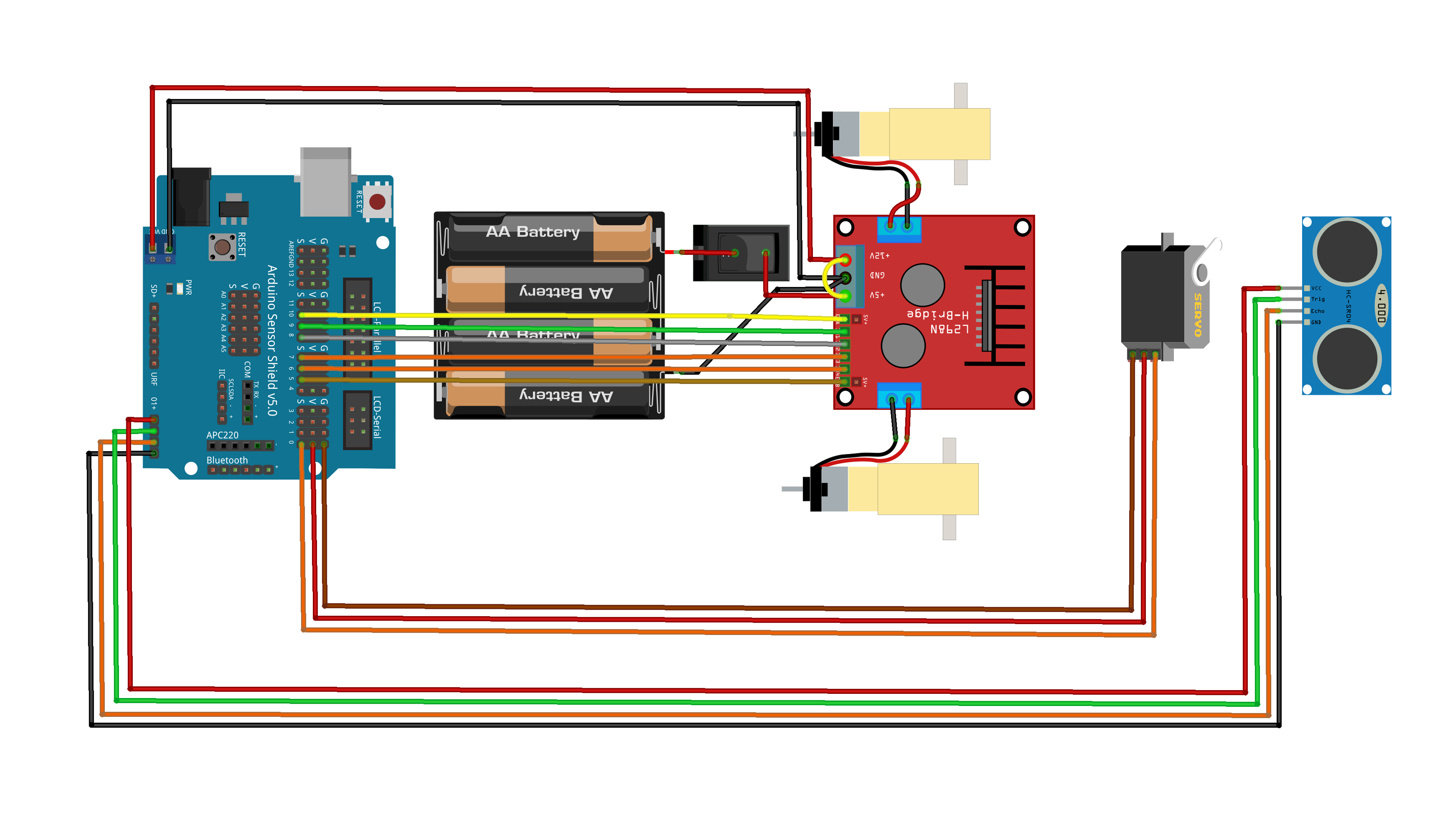
the shield is a Sensor shield v5.0
and the motor controller and ultrasonic sensor are already shown.
tight halo
I need to make sure everything will work before I purchase it!
north stream
I think it will all work, but it's always tough to be "sure".
north stream
The servos are easy, they just need a PWM lead apiece.
A separate servo board is nice, but I don't think you need one. You may need PWM for the motor controller too, I don't know.
tight halo
you do 😐
but then again I saw a guy connect servos to the 8 and 7 pins on the sensor board and still work?
 unreal tinsel
Hi! I'm working with a bluefruit nrf52832 and have some questions. Is this the right place to ask?
Specifically, I updated the boot loader as per the instructions on the site. I'm wondering if it is normal that now every time I upload to my board, it will say "activating new firmware, device programmed". Just trying to double check that I didn't do anything weird to it
fast shard
i have esp8266 wifi module, when i connect it to the arduino then it gives me random characters in my serial monitor, please help someone
attachment is below:
odd fjord
@fast shard I think you can ignore that. . When the ESP8266 boots it puts out some information at a non standard baud rate. Try uploading a sketch and see how it works.
fast shard
also i have one question regarding sending data to my xampp server which i have hosted on EC2 AWS
could you please help me with that?
odd fjord
That is not something I am familiar with. Post your question. Hopefully someone can help.
fast shard
basically, I have xampp server. I want to send data to the server using esp8266, using post method, is there any reference?
safe shell
Similar to GET method, just need to also send the data, may need Content-Type: application/x-www-form-urlencoded header with data in key-value form. did a search for "ESP8266 Arduino POST" and a few things showed up... more clues than fully worked out examples
If the amount of data is on the smaller side, you may be able to use GET with query strings, like ...index.html/?x=123&y=456 to get things going while you work on POST
fiery lichen
So, bummer, it appears on the seesaw board that pwm pins can only be used as pwm and not digital.
Can someone tell me how to send a pwm signal to one of the seesaw pins? I defined pin 5 as
pinMore(5,output)
AnalogWrite(5,255) doesn’t seem to work nor does digitalWrite(5.HIGH)
https://learn.adafruit.com/adafruit-seesaw-atsamd09-breakout/pwm

Sorry, ss.pinMode(5,output)
safe shell
I don't see any PWM examples, but the library code has a function https://github.com/adafruit/Adafruit_Seesaw/blob/abe23cd6c55959f9e28ee100faac5ec6b2d86c08/Adafruit_seesaw.cpp#L399 that seems to behave like an Arduino AnalogOut (PWM)
Separate function to set frequency
fiery lichen
I just got it, I’m an idiot. Forgot it’s not analogWrite it’s ss.analogWrite to tell it you mean the seesaw board and not the micro ....DOH!
safe shell
I didn't realize about the seesaw that the pins weren't as multi-function as we're used to. TIL.
north stream
They can be assigned different functions, but it requires rebuilding the Seesaw binary.
However, the PWM pins might respond to ss.digitalWrite(). If not, the 100% PWM trick might work.
fiery lichen
Yeah I’d love to make them all digital IO for my project but I’m not confident rebuilding binary
Ss.analogWrite(5,255) works....just can only be an output, not input which is a bummer, but I can work around it 🙂
 lusty bear
Hi, is this the right place to ask about nrf52840 feather express coding? Im trying to send multiple data via UART.
How can I possibly do that?
north stream
What do you mean by send multiple data? Sending more than one byte, or having more than one stream of data, or sending encoded data (like floating point numbers)?
lusty bear
Having more than one stream I guess.. because the data im going to send is two different sensor value
cedar mountain
A simple method is to just include a label character with each data value or something, so it looks like "A10.2 A11.9 B312 A10.8 A11.0 B309" etc. and the receiver can pull the data type apart easily.
lost nest
I think you want e.g. Bleuart.print("A:"); Bleuart.println(sensor1);
then same for B
not sure what language you're using, if it's python I think the prints can get merged like you did.
lusty bear
Im using the adafruit Bluefruit application to see the results in the UART terminal it came out okay
But the plotter didnt seems to gave any output
lost nest
That makes sense, the plotter I think assumes just a single stream of numbers
cedar mountain
Heh heh, that would have been helpful to mention in your original question: "How can I send values from multiple sensors in a way compatible with the Bluefruit app's plotter?"
lost nest
The tutorial looks pretty good here: https://learn.adafruit.com/bluefruit-le-connect/plotter
Instead of doing the A/B we suggested
jJust do print one number, then print a comma, then print second number
 stark mist
Hello
anyone around?
I have a general question regarding the adafruit arduino apis, I'm using the arduino ide really for the first time in any depth, however, I cant find how to get to the api reference guide?
I'm use to visual studio where I can tag to functions or headers and read at least the comments or function definitions. Without it I'm feeling rather lost bar the general programming and examples.
I'm wondering how and where I can look up a specific function definition including its parameters for any of the adafruit modules apis?
lusty bear
Hi again, anyone familiar with bluetooth services and characteristics? Is there any tutorial that I can follow to add a characteristics into UART services?
Currently there is two characteristics in the UART services, im trying to add a third. Any tutorial or ideas?
 sharp turret
@stark mist The Arduino IDE doesn't go there. There are some provisions to get VScode to work .
For me, I use Gihub and google. Both the Arduino Library (misnamed as a language) and Adafruit's libraries are all on Github. For example, when I want to look deeper into an Arduino function, I'll search google for "github avrcore <function>". avrcore works for the 8-bit AVR boards.
stark mist
hey
sharp turret
for Adafruit specific libraries, I find it helpful to search "github adafruit <library>" and then using github's "search within repository" from there.
stark mist
thanks Baldengineer
that is pretty much what I resolved to, I tried to use the arduino extension for vs but ran into issues getting it compile
I was really hoping for a nice documentation I'm use to with winapi or qt
pretty much found everything I needed with the method you described
@sharp turret thanks
sharp turret
the arduino library is well described on arduino.cc. for those functions I search "arduino reference <function>"
 gilded jay
guys is it possible to create something
that measure the perceived temperature instead of the effective temperature? I have a BME680 environmental sensor
please quote me if you answer me
safe shell
@gilded jay You can use your temp,, humidity, etc measurements to calculate or look up Wind Chill, Heat Index, etc
zinc rampart
How install ESP8266 for arduino uno ?
I can't compile ESP8266Wifi.h for Arduino UNO
I have a module ESP8266 and i want implement for my board
north stream
Go to preferences and add https://arduino.esp8266.com/stable/package_esp8266com_index.json to Board Manager URLs
Then go to Tools -> Boards -> Board Manager, scroll down to "esp8266 by ESP8266 Community" and click on "install".
However, the Arduino Uno does not have an ESP8266, so I'm guessing you might mean the Arduino IDE. However, you might mean something else (like an Arduino ESP8266 WiFi shield). If that's the case, you'd need to do something different.
zinc rampart
I have this module esp8266
And this arduino
And what I want is to connect the module to my arduino
north stream
You'll need a few things. You'll need a level shifter because the Arduino is 5V and that module is 3V. And you'll need to decide how you want to use the module. Normally they come with firmware that lets you control them with simple "AT" style commands, and you can use these to get WiFi functionality fairly easily.
However, it's also possible to write custom programs for the WiFi module itself.
zinc rampart
That arduino also has 3.3v output
I just want it to connect it to MySQL
I have another "Wemos D1" card and I managed to connect that to MySQL but I would like to connect Arduino UNO with ESP8266
north stream
While the Uno has a 3.3V output, that's just a power supply, you still need to convert the receive and transmit data signal levels (unless it's a 3V Arduino).
You might look at this library: https://github.com/bportaluri/WiFiEsp

GitHub
Arduino WiFi library for ESP8266 modules. Contribute to bportaluri/WiFiEsp development by creating an account on GitHub.
zinc rampart
I will check it, thanks
 grand walrus
Has anyone used a LoRa with a Arduino to receive and transmit radio waves
 low hornet
can i blink the trinket's led or neopixel with setting a eg.50/50 pwm signal of say 5hz? i read the min. freq. for an arduino uno is something like 30hz, how is that going on an M0?
 leaden walrus
yes, for the LED:
Adafruit CircuitPython 5.0.0 on 2020-03-02; Adafruit Trinket M0 with samd21e18
>>> import board
>>> import pulseio
>>> pwm = pulseio.PWMOut(board.D13, frequency=5)
>>> pwm.duty_cycle = 2**15
>>>
neopixels work differently
leaden walrus
oops. wrong language. nevermind, that's a circuitpython example.
stark mist
I'm attempting to figure out the bluetooth le on the CLUE using the ardunio sdk, I cant seem to find any examples specifically for the clue that work, perhaps I'm looking in the wrong place and anyone point me in the right direction please?
stark mist
nevermind found em lol just being blind
lusty bear
Hello, i'm still trying to add extra characteristic to UART service in nrf52840 feather express anyone can lend a hand?
 wintry berry
hi, how do I set the time to something specific with the DS1307? like if ... set the time to 00,00,00,10,03,20 (midnight 10 march 2020)
fervent arrow
can someone help me? I have a nextion display on a esp8266 and I am transmitting it's data over wifi to another esp but nothing is happening when I press the button
#include <NexButton.h>
#include <NexCheckbox.h>
#include <NexConfig.h>
#include <NexCrop.h>
#include <NexDualStateButton.h>
#include <NexGauge.h>
#include <NexGpio.h>
#include <NexHardware.h>
#include <NexHotspot.h>
#include <NexNumber.h>
#include <NexObject.h>
#include <NexPage.h>
#include <NexPicture.h>
#include <NexProgressBar.h>
#include <NexRadio.h>
#include <NexRtc.h>
#include <NexScrolltext.h>
#include <NexSlider.h>
#include <NexText.h>
#include <NexTimer.h>
#include <Nextion.h>
#include <NexTouch.h>
#include <NexUpload.h>
#include <NexVariable.h>
#include <NexWaveform.h>

#include <SoftwareSerial.h>
#include <ESP8266WiFi.h>
//definding butons
//NexButton name = NexButton(page, id, "name")
NexButton b0 = NexButton(1, 2, "b0");

NexTouch *nex_listen_list[] = {
  &b0,
  NULL
  };

//object name pushcallback(void *ptr)

void b0PushCallback(void *ptr) {
  Serial.println("Red1");
  }
//wifi stuff
WiFiServer server(80);
IPAddress IP(192, 168, 4, 15);
IPAddress mask = (255, 255, 255, 0);

void setup() {
  Serial.begin(9600);
  //wifi part
  WiFi.mode(WIFI_AP);
  WiFi.softAP("Wemos_AP", "Wemos_comm");
  WiFi.softAPConfig(IP, IP, mask);
  server.begin();
  Serial.println();
  Serial.println("accesspoint_bare_01.ino");
  Serial.println("Server started.");
  Serial.print("IP: "); Serial.println(WiFi.softAPIP());
  Serial.print("MAC:"); Serial.println(WiFi.softAPmacAddress());
  //nextion sutff
  b0.attachPush(b0PushCallback);
}

void loop() {
  nexLoop(nex_listen_list);
  //wifi stuff again
  WiFiClient client = server.available();
  if (!client) {
    return;
  }
  String request = client.readStringUntil('\r');
  Serial.println("********************************");
  Serial.println("From the station: " + request);
  client.flush();
  //Serial.print("Byte sent to the station: ");
  //Serial.println(client.println("IamAlive\r"));
}```@wintry berry There's an example in the commented-out part here https://github.com/adafruit/RTClib/blob/master/examples/ds1307/ds1307.ino
wintry berry
@safe shell Thank you, but I was solved it.
After really long time I found how to make it work, rtc.begin(); is critical otherwise the RTC will ignore the rtc.adjust, on the year the number can't be smaller then 2000 (I was trying to set it to 1970)
my example code https://paste.debian.net/1134287/
fast shard
Similar to GET method, just need to also send the data, may need
Content-Type: application/x-www-form-urlencodedheader with data in key-value form. did a search for "ESP8266 Arduino POST" and a few things showed up... more clues than fully worked out examples
@safe shell okok
zinc rampart
Which board do you recommend for MEGA with Wi-Fi module?
 humble anchor
zinc rampart
humble anchor
zinc rampart
Yes, because i need 15 sensors
north stream
Depending on the sensors, you may not need a Mega. For example, if they're I2C sensors, they might be able to share a bus.
 signal horizon
hello, I'm looking to get started with my first arduino project, im looking at putting text on some of the LED matrixes, is there a command line script or piece of software I can use to put scrolling strings on?
zinc rampart
Depending on the sensors, you may not need a Mega. For example, if they're I2C sensors, they might be able to share a bus.
@north stream They are: IR, DHT11, FIRE, GAS, RFID
Presence
north stream
Some of those will want individual control leads, yes. You could either use a Mega or an I/O expander with a smaller board. The reason we bring it up is there are more Wi-Fi options in other form factors.
@signal horizon The AdaFruit GFX library supports things like scrolling text. https://learn.adafruit.com/smssenger-bag/smssenger-code
signal horizon
thats a start, i might also mention i am exceptionally un-gifted when it comes to programming
north stream
A fair amount of programming boils down to "find something that does sort of what I want, then remove all the bits I don't need".
signal horizon
i'll have it hooked in through USB
north stream
In this case, a chunk of the example code is concerned with receiving SMS messages, which you probably don't care about. The last dozen or so lines are most of the scrolling part.
signal horizon
so ideally i'd just do -> command "blah" and then blah goes on the screen
i can rig it up to do what i want from there with other software
north stream
There may be a way to do that, but I don't know how offhand.
But I like your modular approach: have one piece that you can call to scroll the message on the display and have other pieces call it.
zinc rampart
Some of those will want individual control leads, yes. You could either use a Mega or an I/O expander with a smaller board. The reason we bring it up is there are more Wi-Fi options in other form factors.
@north stream So what can you recommend me? I need to send all the data to a database, so I use one with a wifi module
north stream
Somewhat depends on your use case. I have a fondness for the Metro M4 AirLift https://www.adafruit.com/product/4000 but there are several other good choices, each with different capabilities and features.
 strong swan
@zinc rampart
Or you can use a different product. Normally i would not say it because Adafruit things are ok. In this case look at the UNO+WIFI from RobotDyn. I use them often for other things. They working very well on the board in the size of the UNO.
 stable raven
Hi. I got this product for a university project where have to use the arduino to make a controller for a game https://uk.banggood.com/Geekcreit-UNO-R3-Improved-Version-2_8TFT-LCD-Touch-Screen-2_4TFT-Touch-Screen-Display-Module-Kit-p-1428291.html?rmmds=search

www.banggood.com
Online Shopping at Banggood.com!
my idea was to use the touch screen as an input for my game. Touchscreen arrived and I have no idea how to use it properly and there seems to be multiple issues.
I plugged the touchscreen into the board (since it was a shield I just had to line it up), downloaded adafruit_GFX and adafruit_TFTLCD and got a sample project running. The problems that came up are:
When I do tft.begin(0x9325); the screen becomes a mess of multi-colored pixels.
and doing something like:
  tft.reset();
  tft.begin(0x9325);
  tft.fillScreen(GREEN);
doesn't seem to work properly either (this code is in setup() ). Only about 1 quarter of the screen actually gets filled
Am I doing something wrong? The project is due in on the 1st of April and it took nearly 2 weeks for this to get delivered only for it to seemingly not work or be broken
woven mica
You need to change the pin numbers according to the shield you have
stable raven
I've tried each one
One gives me glitchy results, the rest gives me a white screen.
north stream
You probably need to choose the right controller and resolution as well.
stable raven
I've tried all of that. I've tried changing 0x9325 to the other stuff, same result (1 that gave me buggy results, the rest gave me a white screen)
This is all I get from 0x9325
And this is what I get when trying to fill the screen
At this point the only thing I can think of is that its broken in some way
stable raven
anyone?
cedar mountain
Have you tried tft.readID() in order to verify what sort of screen you have?
stable raven
That gives me "26633"
north stream
Looks like the "fill green" is working. Screen starts with random data (normal), then green fills as much as it thinks there's room. Might need to set the resolution so the "fill green" knows how big the screen actually is.
stable raven
how do I do that?
north stream
tft.setAddrWindow()?
stable raven
"no matching function for call to 'Adafruit_TFTLCD::setAddrWindow()'" when compiling
wait nvm i got the arguments wrong
yes! that seems to have fixed it
thank you @north stream
but i did just realize there's a dead pixel 
north stream
That's annoying (but common on cheap displays), but hopefully not a show-stopper for your project.
stable raven
na it's fine
is there anything similar for touch? It seems that it only recognizes touch on x:1023 (y seems fine)
nvm seems like I was using the wrong example
stable raven
another question, how should I use setAddrWindow()?
Do I do it like:
setAddrWindow(0,0,320,240)? (320 and 240 being the width and height respectively)
Or a different way?
I ask because I'm having some issues with text being cut off on the screen.
north stream
I think it's inclusive, so 320 pixels would be 0 to 319
stable raven
seems like fill works fine, but stuff like test and lines dont
graphicstest is extremely buggy and the only test that worked fine was the fill test
tft.setAddrWindow(0,0,240,320);
this is according to the store page (tft.width() and tft.height() give completely different results which also don't work)
 cerulean verge
Hello, guys.
I am trying to make a drum machine with arduino, mosfet and solenoids and I found these: https://www.youtube.com/watch?time_continue=17&v=pOi2FUBZz5A&feature=emb_title I believe these are servo motors, yes? And what voltage would be enough to strike drum as in the video?


Thank you!
cedar mountain
It's not really a voltage question per se. Motor gearing, power, current, etc. matter too.
cedar mountain
But yes, those are servo motors. I can't see a part number in the project notes, so it's hard to estimate how much power or torque they require.
north stream
Servos generally run on 5V, and take a control signal to tell them which position to move to.
cerulean verge
I see. But I wonder if 5V could strike so hard?
 runic yacht
I've got an Adafruit vl6180x distance sensor working on an Itsy Bitsy 32u4 (5v). It works great when connected to my laptop and the Arduino serial monitor is open. But it does nothing when I connect it to an external power source or even connected to my computer without the Arduino serial monitor running. What could I be doing wrong here?
north stream
Some code waits for the serial port be be open before starting.
runic yacht
I suspected that and tried to comment anything that referenced communication, but somehow the code still wanted a serial connection. I was wondering if the library for the VL6180x necessarily needs serial to work.
Here's a video of my contraption in action. It's a cup-detection circuit for a cocktail robot I'm building. https://photos.app.goo.gl/kauKJ76xuug7ckdb9

Google Photos
 fallen linden
@runic yacht Did you also comment out the serial.begin() in setup?
runic yacht
I'll give it another go and see what happens. Thanks Jack. It's reassuring just to hear I was maybe on the right track.
 digital stump
Can anyone help me out please?
I've been spending all day trying to get AT commands to work on my Arduino nano
I can send the data but I don't see anything come back even though I configured everything according to this site: http://www.martyncurrey.com/hm-10-bluetooth-4ble-modules/#HM-10 - AT commands
 wraith current
@digital stump post a picture of how you have it wired up.
digital stump
@wraith current
Following this Schematic but not getting any response In Serial Monitor
north stream
Looks like you're using RXD (instead of D9) as TX, and TXD (instad of D8) as RX. At a minimum, you'd need to swap them and change your software.
 floral thicket
Hey guys, I have the Adafruit RGB Shield Part 714 that has the 5 i2c pushbuttons on it, and I was wondering how I attach an interrupt to one of those buttons. I tried using the attachinterrupt command but it didn't seem to work
stable raven
does anyone have an example of how to use getTextBounds?
the documentation just tells me what the arguments mean but that doesn't give me a clear idea of how I'm supposed to use it
cedar mountain
@floral thicket You probably can't use interrupts there, since the buttons are only connected over I2C. They would need to be periodically polled for their status.
floral thicket
Ok, that makes sense than as to why the existing prototype at work(which we have lost the code for) uses external buttons instead of the i2c ones
stable raven
  if(c!='<'){
    str.concat(String(c));
  }
  else if(c=='<' && str.length()>2){
    str.remove(str.length()-1);
  }
  tft.setTextColor(WHITE,BLACK);
  tft.setCursor(0,0);
  tft.print(str);
Trying to find a faster way to clear text on the display. Currently I'm using the second argument of setTextColor to 'clear' the text which works fine for typing, but as you see I have an if statement that makes is so when the character < is sent, it should delete the last character in the string (backspace, essentially). When back spacing, it doesn't actually update the screen/text and causes some weird stuff to happen
(reason why I was asking about getTextBounds was because I was thinking about using it to just draw a black rectangle over the text rather than clearing the entire screen)
woven mica
Just print the longer string with background color and then draw the string with removed character with text color?
floral thicket
Any idea why using lcd.clear() in an interrupt is causing my code to freeze?
I am using the adafruit rgb shield library on an Uno R3 if that helps
north stream
In general, interrupt service routines should complete quickly, and I'm guessing lcd.clear() has to write out data to the entire LCD buffer. You may be better off just having the ISR set a "clear request" sort of flag, and then the main loop call lcd.clear() if that flag is set.
surreal pawn
doesn't the adafruit gfx library on samd try to use DMA to send pixels to the screen?
oh, I see you're not asking about any of those
elder hare
so i have some dot led matrix (32 in total in series) that uses MAX7219 to drive each one! now using a short cable and using 3.3v on the ESP32 they all work fine and the text scrolls all the way.
The problems comes when i connect ESP32 and the dot led matrix to external PSU 5V 10A with common ground and CLK, DIN and CS on the ESP32. What happens is the text starts scrolling (from left) and about midway / at the end the text fades/goes away/ goes in and out with some of the matrix turning completely on and off and flickering :S
why could this be? to loong wires (CLK, DIN, CS) or a power issue? :S (the PSU is 10A so that should be way more then enough, as stated i can drive these directly from my ESP32 with 3.3V and no flickering and the text scrolls all the way through)...
north stream
It could be that with a 5V supply, the 3.3V signal from the ESP32 is marginal to drive all the clock and latch inputs (the MAX7219 data sheet specifies a minimum of 3.5V). Perhaps try level shifters/buffers for the clock and latch signals?
 sonic relic
is their a type of IC that works like a potentiometer where i can change the output voltage through code instead of a twiting nob
cedar mountain
Yep. "Digital potentiometers" are a thing. Or if you just want a voltage instead of a resistance, that's a DAC.
odd fjord
for example -- https://www.adafruit.com/product/4286

If you're a person like me that gets exhausted turning knobs all day, the DS3502 is just the ticket to calm all your knob-turning related troubles. Instead of having to turn ...
sonic relic
thanks for the help :)
elder hare
i just recently got a ESP32 (had a ESP8266 befor) and on my ESP8266 i could send webrequests every second but on my ESP32 after receiving just 1 makes it stop receiving so like this (random)
- POST
- NO POST
- NO POST
- POST
- POST
- POST
- NO POST
yea you get the idea and it is random sometimes i can send it 6 POST within 6 second...
to be clear, im sending POST requests TO my ESP32 via python
wraith current
@elder hare esp32 can sometimes be strangely buggy compared to the 8266. Wifi joins can be sketchy, reading adc while using wifi sometimes just doesn't work, etc.. . .
elder hare
@wraith current so i noticed :S is there a fix for this behaviour?
wraith current
i don't know of one.
 still mural
Not sure if I should post in CP or Arduino but are there any differences in support for peripherals/libraries if I use a Crickit with Arduino instead of CP?
north stream
I think both libraries support all the Crickit peripherals.
signal horizon
hi, im new to arduino, i have a nano and i wired up a neopixel 8x8, put in the caps and resistors but im not getting any lights on
is there a debug command i should be looking for?
north stream
There's not really a debug command, per se, since NeoPixels don't return any data. The Arduino has no way of even knowing if NeoPixels are there, it just sends the data stream.
So the problem reduces to finding out why nothing lights. One obvious possibility is a power supply problem. The other is the data stream: is it being sent, and is it being received?
 grand lodge
@signal horizon most helpful if you can give us a photo of your circuit (clear) and tell us what sample code you're using
stark mist
@here I've been playing with the Clue and Raspberry pi BLEuart connection and I've found that for very small packets of bytes it seems to work quite well, however, once I get into streaming sensor data from the clue to the pi I'm hitting some kind of transmission error that introduces noise into my stream. I'm thinking about implementing checksums for each message as a way to determine if I should accept the message or not.
I wanted to check though and see if anyone had experienced this and if there is a smarter way around it, I was looking at the object transfer service but I cant find any exposing of that functionality in the ada fruit libraries, also frankly I'm not sure if that would solve my problem?
a tcp style connection that can validate the data packets and re-request dropped / corrupted
however if it gets that complicated I was thinking of just connecting the clue and pi via a uart cable instead of using the ble connection
 burnt island
I don't think the nordic UART service makes any consistency promises. If you want to get fancy you could break your sensors into separate BLE characteristics and subscribe to them from the Pi. You might miss individual sensor updates but you shouldn't have any corruption
IIRC the nordic UART service is made of two characteristics, one read and one write. The read/send characteristic hold the latest character "sent" from the Clue and gets read by the other device (Pi) at some point, but there is no indication of if that value had been read or not
so, as you're seeing it's possible to change the "send" byte before anything gets a chance to read the old value
stark mist
I think that makes sense as mostly I'm seeing missing characters
I'm also refactoring my approach to deal with sending each sensor as updates only a few bytes long
signal horizon
@grand lodge it was my cap, I got the wrong kind, 10v and it needs 6.3v
grand lodge
yay glad you fixed it !
signal horizon
Is there a command line application that I can use for Sr ding commands? I’m trying to find a way to make something to send a command for a text string and have it displayed on my LED matrix
fiery lichen
Is there a technical term for a circuit that turns 3.7v into 5v? I know Adafruit calls them powerboost, but if I’m looking for a higher current one on other sites, what would I search for?
odd fjord
I believe you are looking for a "boost" converter
north stream
Pololu calls them boost regulators, another possibility
 cinder knoll
Has anyone powered an Arduino from a lightbulb socket?
I am seeking to make my own smart bulb using an Arduino
north stream
You basically need a small power adapter to step down the voltage. There used to be chips available to do that, but they weren't very safe and I don't think they're made any more.
@signal horizon I'm also glad you got it working, but normally you can use a 10V capacitor where a 6.3V one was, with no problems.
signal horizon
Hmmm
cinder knoll
Can someone help direct me what I should read into to understand the decisions he is making in this video with his circuits?

Support me for more videos: https://www.patreon.com/GreatScott
Previous video: https://youtu.be/ZAqNKaX3LQ0
Facebook: https://www.facebook.com/greatscottlab
Twitter: https://twitter.com/GreatScottLab
More project information (schematic, code, parts list,...) on Instructables:...
north stream
I might be able to help you with this, but which decisions are you curious about?
cinder knoll
I want to design something similar. However it would drive two different series of LED strips
So when I watched how he designed he circuit. I was curious as to why he chose certain components for each
He did explain why he built the smaller circuit to smooth out the voltage. I understand why he built it, but not what conclusions he made to determine how he would design such a circuit
My goal is to use an esp8266, powered from usb or dc, and be able to turn on and off a white led strip and a uv led strip so that I can have a smart bulb to display an artwork that can be seen in both uv and visible light
I believe, since the esp8266 can only drive so much current from it's 3.3v pin. I would have to passthru power from the wall, and control a switch or gate with the esp8266 in order to turn on and off the circuit
north stream
Ah, so you're looking for at least two things: one on how filters are designed, and one on how to control LED power from the mains.
There are two basic approaches for controlling mains-powered devices. One is to simply use mains powered devices with their own power supplies that are designed to plug into the wall, and switch power to them. This can be done with relays, optically isolated triacs, or ready built modules.
The other is to have a power supply that converts the mains voltage into something the LEDs can use (such as 5V DC or 12V DC), and then switch that power to the LEDs (generally using a transistor).
This writeup might be useful to you, describing how different filter components affect the amount of ripple in the resulting power https://learnabout-electronics.org/PSU/psu12.php
 glass vapor
Hello! I have a quick question. An Esp32 can run off of micro python. Can I use the esp32 by itself or does it have to be with an arduino?
north stream
Yes, you can use it by itself.
glass vapor
Alright, awesome
 viscid ether
hi, i need some help with this
i have 2 adafruit tcs34725 sensors, and i cant get them both to work in the same arduino, because they have the same i2c adress. how would i fix that?
cedar mountain
Easiest way would be to use a software-I2C library to get a second bus, if your Arduino has only one to start with.
viscid ether
what library do you recommend for having more than one bus? i had that idea, but couldnt find any
cedar mountain
Don't have any personal experience with one, but it looks like there are a number out there, just searching for "Arduino software I2C".
viscid ether
ok. thanks for your help
 north kelp
@viscid ether @cedar mountain Another option is to use Adafruit's I2C Multiplexer:
https://www.adafruit.com/product/2717

You just found the perfect I2C sensor, and you want to wire up two or three or more of them to your Arduino when you realize "Uh oh, this chip has a fixed I2C address, and from what I ...
cedar mountain
Good point, thanks!
lusty bear
Hi. Im trying to program a custom board of samd21 with a m0 bootloader. In the tutorial the bootprotect is set to 0x07. But in the new version of atmel studio, it didnt show any address at the bootprotect instead the dropdown menu shows byte size.. so what size should I pick?
cedar mountain
The 0x07 value seems to correspond to a bootloader size of 0, i.e. no protection.
lusty bear
How about 0x02? What is the size? @cedar mountain
cedar mountain
Looks like 8KB.
lusty bear
Okay thank you Ed
cedar mountain
Table 21-2 in the SAMD21 datasheet if you want to double-check.
lusty bear
Cheers Ed thank you and stay safe amid this covid pandemic.
cedar mountain
Heh heh, I have just over an hour before a "shelter in place" order goes into effect for my area. Last chance to party! 😉
 calm crown
someone knows what this means?
north stream
It means to print out the contents of the PORTB register (which describes a group of GPIO pins) in binary.
pine bramble
Can anyone help me with my arduino alarm clock
I'm having probs opening serial port to upload
north stream
You mean, uploading a sketch via the serial port?
reef pollen
If I'm not mistaken some UNO use a 16u2 and some use a ch340g as serial converters?
Do you think there's an efficiency drop when comparing an external hardware serial ch340, ft232r, etc to the internal of a 32u4?
I would wager that the external chips have to transfer the data over ftdi? spi? while the 32u4 probably has an internal serial memory buffer.
The reason I ask is enabling serial debugging on my project works on my promicro (32u4). On a nano (ch340), the serial seems to be taking longer and slowing the loop down considerably to the point where my project timing fails. (reading a gamecube controller. kind of timing specific)
Just wondering if its a serial effiecneny thing, or if the 328p with ch340 should be fast enough and theres something else wrong.
next step for me I think it to hook up my data analyzer or my scope and test timing, but I don't own a nano, trying to debug my program for someone else's hardware. Going to test on my UNO rev1
If Yall have any personal anecdotes about projects working on different types of boards, or info about how the 328p commicates with external converts, or anything that might be helpful for me to find the answer myself, I'd appreciate it!
</wall-of-text>
calm crown
@north stream but what means the BIN
odd fjord
@calm crown it sets the output format -- in this case binary, see this page https://www.arduino.cc/reference/en/language/functions/communication/serial/println/
odd fjord
the default is decimal so you don;t have to specify it or you can use DEC
calm crown
i think i get it, but i'll just have to test it out and see what it types in my serial monitor
Thanks 
odd fjord
Serial.println(PORTB) is same as Serial.println(PORTB,DEC)
You're welcome -- good luck!
north stream
@reef pollen I'm guessing something else is wrong: all the USB to serial adapter chips are capable of keeping up just fine even at 115,200kbps.
There could, theoretically, be some sort of problem with the USB driver on the host side, but all the problems I've seen with host driver issues have been of the "I can't talk to the board" sort, not speed/latency/delay issues.
reef pollen
@north stream I just wonder if one chip takes up more cpu cycles (for Serial.write) compared to the others.
 lunar yew

skribbl.io - Free Multiplayer Drawing & Guessing Game
Skribbl.io a free multiplayer drawing and guessing game. Draw and guess words with your friends and people all around the world! Score the most points and be the winner!
north stream
@reef pollen No, the main CPU just sends serial data to the USB-serial chip (whatever it is).
Except for boards like the 32U4 ones where the main CPU also serves as the USB-serial link (I'm not very sure what the serial impact is on those chips, but I would expect it to be small, as it's probably still hardware based).
 ripe hedge
Any idea where I can get nuts that fit the adafruit encoder? I have a bunch of pots that don't have nuts and they are kind of useless without them. I looked up the size and bought these but they are way too big https://www.amazon.com/dp/B07BV37JBY/ref=cm_sw_r_fm_apa_i_iZzCEbXVKZRVN
cedar mountain
According to the datasheet you want M7 nuts.
cedar mountain
M7 x 0.75, sorry.
 narrow thorn
Did people know that Arduino has a cert? https://store.arduino.cc/digital/cert_fundamentals

Arduino Digital Store
The official Arduino store for digital products. Browse online services and explore digital plans and platforms integrated with Arduino family.
I'm not sure on it's usefulness, but cool to see.
signal horizon
anybody know of a better 8 point font for neopixel? the default one is kind of messed up. T's are like an underlined T
theres a line at the bottom, looks like a capital i in some ways
signal horizon
turns out it was the zigzag directive messing things up
north stream
Good job figuring that one out, that sounds subtle and annoying.
 hollow night
Any nifty PID codebase in Arduino yet ? I am trying to control windshield wiper motor for set point of tidal volume in home brew ventilator with a medical grade analog pressure sensor.
lost nest
What is the intended purpose of the ventilator? Are you just doing it as a fun experiment to see what it's like to build one?
cedar mountain
I presume this is a crowdsourced coronavirus response design.
lost nest
Yeah, so I'd highly encourage anyone who wants to work on that to first read: https://en.wikipedia.org/wiki/Therac-25
The Therac-25 was a computer-controlled radiation therapy machine produced by Atomic Energy of Canada Limited (AECL) in 1982 after the Therac-6 and Therac-20 units (the earlier units had been produced in partnership with CGR of France).
It was involved in at least six accident...
hollow night
This is part of world wide efforts from over 16k folks so far. (More at https://www.facebook.com/groups/670932227050506/ ). My effort will be using NXPs MP3V5010G (with range 0-1.45 psi, with analog output) as the initial sensor candidate for the open source emergency ventilator when the medical grade ones run out.
It will be refind/iterated on with high end DAQ card testing and LabVIEW.
What is the intended purpose of the ventilator? Are you just doing it as a fun experiment to see what it's like to build one?
@lost nest To give people who are turned away a chance.
I presume this is a crowdsourced coronavirus response design.
@cedar mountain Indeed.
lost nest
I'm sure there are libraries available, PID control is a pretty common thing. The big thing that I would advise is getting as much input as you can about what could be harmful to the patient, and incorporating hardware lockouts to prevent them. And also making sure you can detect when the system stops working.
Commercial life-support hardware/software is held to an incredibly high standard of testing and quality, and it seems to me like what you're trying to do could be done by a person manually squeezing the bag
So you will want to make sure that what you end up making isn't worse than just having a person do it.
hollow night
So you will want to make sure that what you end up making isn't worse than just having a person do it.
@lost nest the record for a human doing it is four days. We need this done for 2ish weeks for potentially hundreds of thousands of people.
 sage anvil
i made a small code with the keyboard library for an atmega32u4 chip
its using pin 11 as a pullup but no matter what state its in it just types
and now it wont work at all
north stream
Keyboard or keypad? Is this using HID code on the USB side?
pine bramble
im making a arduino mouse with a pro micro but i want the the cursor in the middle when the joystick is in the middle can someone help me?
heres the code
#include <Mouse.h>
int horzPin = A0;
int vertPin = A1;
int selPin = 9;
int vertZero, horzZero;
int vertValue, horzValue;
const int sensitivity = 100;
int mouseClickFlag = 0;
//int invertMouse = 1;
int invertMouse = 1;
void setup()
{
pinMode(horzPin, INPUT);
pinMode(vertPin, INPUT);
pinMode(selPin, INPUT);
digitalWrite(selPin, HIGH);
delay(1000);
vertZero = analogRead(vertPin);
horzZero = analogRead(horzPin);
Mouse.begin(); //Init mouse emulation
}
void loop()
{
vertValue = analogRead(vertPin) - vertZero;
horzValue = analogRead(horzPin) - horzZero;
if (vertValue != 0)
Mouse.move(0, (invertMouse * (vertValue / sensitivity)), 0);
if (horzValue != 0)
Mouse.move((invertMouse * (horzValue / sensitivity)), 0, 0);
if ((digitalRead(selPin) == 0) && (!mouseClickFlag))
{
mouseClickFlag = 1;
Mouse.press(MOUSE_LEFT);
}
else if ((digitalRead(selPin)) && (mouseClickFlag))
{
mouseClickFlag = 0;
Mouse.release(MOUSE_LEFT);
}
}
north stream
A mouse is a "relative" device, it just sends how far to move and in what direction, it doesn't set the cursor position directly. Normally joysticks are set up so the middle position is "don't move" and other positions send move information in various directions.
pine bramble
sorry im not goood at coding
can you put a button that makes it go to the middle
thanks
@north stream
north stream
Makes what go to the middle? Is there a screen somewhere? What kind of screen? How is it hooked up?
pine bramble
oh
the cursor
oh
its just a joystick connected to a pro micro and when it is connected to the computer, it acts like a mouse
its a windows 10 pc
and connected by usb
north stream
Unfortunately, there's no way for a mouse to know where the cursor on a PC is, so it doesn't know which way to move to put the cursor at the middle. You would need some other kind of device besides a mouse to do things like set the cursor position to a specific location.
north stream
It looks like there may be a way to make a mouse device work in "absolute" mode where you can set a specific position, but it looks complicated https://forum.arduino.cc/index.php?topic=94140.0
north stream
Like I said, a mouse is normally a "relative" device. Moving the mouse down and to the left sends commands to the computer to move in that direction.
north stream
The mouse has no way of knowing where the cursor currently is, it just says which way to move it from its current position (whatever that is)
pine bramble
can you make the mouse go in the middle in this code?
void setup(){
}
void loop(){
for(int y = 1; y <= 100; y++){
for(int x = 1; x <= 100; x++){
delay(100);
Mouse.move(x, y);
}
}
}
north stream
Nope, that code will just move the mouse in an increasing zigzag.
pine bramble
ok
north stream
To move the cursor to a specific place, you'd need an "absolute" pointing device like a graphics tablet instead of a mouse.
pine bramble
can you not loop that
ohhhhhhh i get it
but on this page(https://forum.arduino.cc/index.php?topic=94140.0) there is a HID.cpp
USB Absolute Mouse Mode
what is that hid.cpp file
north stream
Right, that appears to be a way to operate the mouse in absolute mode, but it looks complicated. That file is part of the Arduino code itself.
pine bramble
ok im gonna try it then
north stream
Like it says, make a backup copy of the file before you change it.
pine bramble
ok
how do you use the cpp file
nvm
will this work?
#include <Mouse.h>
int horzPin = A0;
int vertPin = A1;
int selPin = 9;
int middle = 8;
int vertZero, horzZero;
int vertValue, horzValue;
const int sensitivity = 400;
int mouseClickFlag = 0;
//int invertMouse = 1;
int invertMouse = 1;
void setup()
{
pinMode(horzPin, INPUT);
pinMode(vertPin, INPUT);
pinMode(selPin, INPUT);
digitalWrite(selPin, HIGH);
delay(1000);
vertZero = analogRead(vertPin);
horzZero = analogRead(horzPin);
Mouse.begin(); //Init mouse emulation
}
void loop()
{
vertValue = analogRead(vertPin) - vertZero;
horzValue = analogRead(horzPin) - horzZero;
if (vertValue != 0)
Mouse.move(0, (invertMouse * (vertValue / sensitivity)), 0);
if (horzValue != 0)
Mouse.move((invertMouse * (horzValue / sensitivity)), 0, 0);
if ((digitalRead(selPin) == 0) && (!mouseClickFlag))
{
mouseClickFlag = 1;
Mouse.press(MOUSE_LEFT);
}
else if ((digitalRead(selPin)) && (mouseClickFlag))
{
mouseClickFlag = 0;
Mouse.release(MOUSE_LEFT);
}
if (digitalRead(middle) == 0)
{
Mouse.move(100,100);
delay(1000);
Mouse.move(50,50);
}
}
@north stream
north stream
I don't think so. It looks like a mix of relative and absolute modes.
pine bramble
i have the .cpp file installed
it says it needs platform.h
but i think that got removed
north stream
You might be able to stay with relative mode and send moves so far that you know the cursor is stuck in a corner (so you know where it is) then send moves to send it from there to the middle of the screen. It might look goofy, but it could work.
north stream
Ah. Does it work?
pine bramble
no
north stream
I'm used to computer screens being higher resolution than 100x100.
pine bramble
no
the 100
its like a map on your screen so no matter what, 100,100 is the corner
north stream
A, that would be absolute mode, and B, I don't think they're percentages
north stream
However, it's possible to find out. What does happen when you click the middle button?
pine bramble
i cant upload it
because it says it needs platform.h
but people say that that libary got removed
north stream
Did you change hid.cpp?
north stream
Delete that file.
pine bramble
ok
north stream
Now does it upload?
pine bramble
yes
but im not sure if it works
let me get a button
real quick
it just keeps it in the corner
the cursor
@north stream how do you make the loop stop
if (digitalRead(middle) == 0)
{
Mouse.move(-50,-50);
delay(1000);
}
can you make that stop
because it just lops
loops
alright
im just not going to do that
i kinda give up
north stream
Yeah, that means "move the cursor -50 pixels in the X direction and -50 pixels in the Y direction once a second for as long as the middle button is held down"
You probably want something like ```c
Mouse.move(-3000, -3000); // move cursor all the way to the corner
Mouse.move(640, 512); // move cursor from the corner to here
You could do something like wait until the button is released
pine bramble
alright
 patent cedar
Hey guys, I am really new to programming and Arduino (using a ESP8266 but with Arduino IDE) and I am trying to home automate a TV lift. I already soldered two relais shields to the ESP8266 and am able to control them seperatly. Now I wanted to add the Alexa compatibility and it works with simple on/off like this:
`if ( (strcmp(device_name, "Lift1") == 0) ) {
if (state) {
      digitalWrite(D3, LOW);

      digitalWrite(D2, HIGH);
      Serial.printf("Lift1 moving up.");
    } else {

      digitalWrite(D3, LOW);

      digitalWrite(D2, HIGH);
      Serial.printf("Lift1 moving down.");`
now I want both relais turned off, before the next action starts, so that I can be sure that the two relais wont be on at the same time. after switching both to low I want to wait 5 seconds (delay), then switch one of the relais to high (either up or down) and after 45 seconds (approx how long the lift needs to fully go up or down), it should switch both relais to low again.
if ( (strcmp(device_name, "Lift1") == 0) ) { if (state) { delay(1000); digitalWrite(D2, LOW); digitalWrite(D3, LOW); delay(5000); digitalWrite(D2, HIGH); delay(45000); digitalWrite(D2, LOW); Serial.printf("Lift1 moving up."); } else { delay(1000); digitalWrite(D2, LOW); digitalWrite(D3, LOW); delay(5000); digitalWrite(D3, HIGH); delay(45000); digitalWrite(D3, LOW); Serial.printf("Lift1 moving down."); } }
I tried it like this but it only switches both off and nothing happens afterwards :/
north stream
What is this if statement inside? The loop?
sage anvil
Keyboard, its only for 1 button
patent cedar
it is in a fauxmo function. it just check whether I said to turn "on" or "off"
north stream
There's not much to go wrong, it seems like either it's not getting called, or the strcmp() is failing.
patent cedar
well I didnt change the function from step 1 to step 2 though
so it cant be that strcmp is failing and the text is even output in the serial monitor
so the if statement is running till the end
north stream
The first time, or the second time?
You could simplify it too: ```c
if (strcmp(device_name, "Lift1") == 0) {
delay(1000);
digitalWrite(D2, LOW);
digitalWrite(D3, LOW);
delay(5000);
digitalWrite(state ? D2 : D3, HIGH);
delay(45000);
digitalWrite(D2, LOW);
Serial.printf("Lift1 moving ");
Serial.printf(state ? "up" : "down");
}
both
with your code the same - serial monitor outputs "Lift1 moving up" but nothing happens
both relais stay off
north stream
Curious.
patent cedar
very confusing 😩
 tender bronze
Hello anyone has worked with AMG8833 IR Thermal Camera for see in a 2.4TFT touchscreen V2.1_9341? I cant understand how work the data. I use the rinkydinky library for touchscreen and the Adafruit_AMG88xx library for thermal camera.
wraith current
@patent cedar maybe your relays are using too much power. digital pins can only supply a little current.
patent cedar
but they are working flawlessly with the first test
if ( (strcmp(device_name, "Lift1") == 0) ) {
if (state) {
      digitalWrite(D3, LOW);

      digitalWrite(D2, HIGH);
      Serial.printf("Lift1 moving up.");
    } else {

      digitalWrite(D3, LOW);

      digitalWrite(D2, HIGH);
      Serial.printf("Lift1 moving down.");
this code works
wraith current
so it gets stuck at delay(45000) ?
wraith current
Put some Serial.print lines in at each line to see exactly which line it's getting stuck at.
patent cedar
well it outputs the very last line "Lift moving up."
so it shouldnt get stuck anywhere but one sec
wraith current
you can user Serial.println("blah"); and it'll make each print a new line.
patent cedar
00:22:23.538 -> [MAIN] Device #0 (Lift1) state: ON value: 255
00:22:23.538 -> Both LOW.D2 HIGH.D2 LOW.Lift1 moving up.[MAIN] Device #0 (Lift1) state: ON value: 254
00:22:23.740 -> Both LOW.D2 HIGH.D2 LOW.Lift1 moving up.
even though I have delay 1000 in the code it doesnt wait 1000
delay(1000); digitalWrite(D2, LOW); digitalWrite(D3, LOW); Serial.printf("Both LOW."); delay(1000); digitalWrite(D2, HIGH); Serial.printf("D2 HIGH."); delay(1000); digitalWrite(D2, LOW); Serial.printf("D2 LOW."); Serial.printf("Lift1 moving up.");
wraith current
`
`
Serial.println("delay 1000");
delay(1000);
Serial.println("D2 low");
digitalWrite(D2, LOW);
Serial.println("D3 low");
digitalWrite(D3, LOW);
Serial.println("delay 1000");
delay(1000);
Serial.println("D2 HIGH");
digitalWrite(D2, HIGH);
Serial.println("delay 1000");
delay(1000);
Serial.println("D2 LOW");
digitalWrite(D2, LOW);
Serial.printf("Lift1 moving up.");
`
try it like that.
 twilit hare
hey... was wondering if anyone knew of an RTC libraries for the SAMD51 (Grand Central). I just picked one up the other day, and am in the process of porting my code from my SAMD21.... but the RTC lib doesn't work!!! I guess I can hack something together if I can't find anything...
north stream
Weird, it's just an I2C peripheral
lost nest
@twilit hare When you say 'doesn't work' what do you mean?
twilit hare
@lost nest I'm attempting to use the internal RTC (since the Grand Central has a 32K crystal already attached). The code that I've been using with my M0 Feather is the RTC Zero code (https://github.com/arduino-libraries/RTCZero)... I get compile errors when I try to compile the code against the SAMD51.
I could use an external RTC (I've got a few lying around...).... but trying to shoot for a minimalist approach
lost nest
Is it failing to compile, failing to execute, something else?
ah sorry missed your saying compile error
It is a different core processor
Even though they're both SAMD, it's one of their cortex-M4 vs cortex-M0. So some careful comparison of the peripheral sets will need to be done.
twilit hare
yeah, I know. I was hoping that someone already created a library.... but, it looks like I'll either create one, or use an external RTC
lost nest
It's possible it's the same core peripheral, but if the libraries for the M4 SAMD don't expose the necessary variables (e.g. https://github.com/arduino-libraries/RTCZero/blob/master/src/RTCZero.cpp#L46) then you'll either need to define those or find some other strategy.

GitHub
RTC Library for SAMD21 based boards. Contribute to arduino-libraries/RTCZero development by creating an account on GitHub.
It looks like someone already did this: https://github.com/ericbaril72/RTCZero/tree/SAMD51_E54

GitHub
RTC Library for Arduino Zero and MKR1000. Contribute to ericbaril72/RTCZero development by creating an account on GitHub.
twilit hare
yeah, I found that one... it's not compiling for me either. I'll take a closer look at it this weekend
could be user error
lost nest
You're kind of deep into the underlying source structure for Arduino, which, IMO, isn't a great place to be.
I've never had a great time with their code structure, but also possibly just me.
twilit hare
yeah... I'm 99% sure that I'll go with an external RTC, in order to keep my project moving along
lost nest
Sticking with a known I2C peripheral helps a lot on portability
If you've got a project in mind, I also vote external RTC to make progress, you can always condense later if it becomes important
twilit hare
yup. Thanks for spending a few minutes helping me to think this through!
lost nest
happy to
lunar yew
 sage anvil
i made this for a small keypad and i used it before and it worked perfectly fine
all of a sudden it doesnt matter what state the switches are itll output anyway
anyone know what could be wrong here
north stream
Maybe move Keyboard.begin(); into setup() instead of loop()?
 lean crypt
Question for someone on the know with the MLX90393. The Adafruit library never actually sets speed for the I2C, is it changeable or does it just assume the speed of the controller?
/**
 * Initialises the I2C bus, and assigns the I2C address to us.
 *
 * @param i2caddr   The I2C address to use for the sensor.
 *
 * @return True if initialisation was successful, otherwise False.
 */
bool Adafruit_MLX90393::begin(uint8_t i2caddr){
    bool ok;

    switch(_transport) {
        case MLX90393_TRANSPORT_I2C:
            _wire->begin();
            _i2caddr = i2caddr;
            break;
        case MLX90393_TRANSPORT_SPI:
            /* Currently not handled due to HW layout. */
            break;
    }

    /* Set gain and sensor config. */
    ok = setGain(_gain);

    /* Set the initialised flag based on the I2C response. */
    _initialized = ok;

    return ok;
}
can someone help me?
im trying to add a button to this code but it keeps on giving me errors
#include <Joystick.h>

Joystick_ Joystick;


int RxAxis_ = 0;
int RyAxis_ = 0;
int RzAxis_ = 0;
int Throttle_ = 0;

const bool initAutoSendState = true;

void setup()
{
      Joystick.begin();
  }

void loop(){


RxAxis_ = analogRead(A1);
 RxAxis_ = map(RxAxis_,0,1023,0,255);
 Joystick.setRxAxis(RxAxis_);

 RyAxis_ = analogRead(A2);
 RyAxis_ = map(RyAxis_,0,1023,0,255);
 Joystick.setRyAxis(RyAxis_);

 RzAxis_ = analogRead(A0);
 RzAxis_ = map(RzAxis_,1023,0,255,0);
Joystick.setRzAxis(RzAxis_);

Throttle_ = analogRead(A3);
Throttle_ = map(Throttle_,1023,0,255,0);
Joystick.setThrottle(Throttle_);

delay (50);
}
Can you post the error? also can you surround your code with ```
pine bramble
alright
odd fjord
@pine bramble please do not use the "everyone" tag --(even though it is disabled) -- in your code the last use of "Throttle" has an underscore at the end that does not belong.
pine bramble
alright sorry
odd fjord
oops never-mind - I did not see it is used above...
pine bramble
lol
can you help me add a buutton into that code?
its connected to gound and pin 9
im using a pro micro
odd fjord
there is a good exampleof how to read a button here https://www.arduino.cc/en/tutorial/button
pine bramble
i dont want it to control a led though
I want it to give an input to the computer
im making a game controller
odd fjord
its just an example -- you can do whatever you want once you detect the button press.
pine bramble
i know that but I dont know how to code that button give an input
odd fjord
I'm not sure what you mean by "give an input"
pine bramble
give an input to the computer
odd fjord
sorry -- I'm confused. I still don't really understand what you are trying to do.
pine bramble
I got all the analog inputs
but see all those red circles?
those are all buttons
and you can add up to 32 of them
also, what are these values?
Throttle_ = map(Throttle_,1023,0,255,0);
the 1023,0,255,0
odd fjord
this bit of code will let you test the button - you need tadd code to do whatever you want to do when it is pressed or not pressed. You should be able to add this to your program```const int buttonPin = 9; // the number of the pushbutton pin
// variables will change:
int buttonState = 0; // variable for reading the pushbutton status
void setup() {
// initialize the pushbutton pin as an input:
pinMode(buttonPin, INPUT);
}
void loop() {
// read the state of the pushbutton value:
buttonState = digitalRead(buttonPin);
// check if the pushbutton is pressed. If it is, the buttonState is HIGH:
if (buttonState == HIGH) {
// The button is pressed
// do something here
} else {
// the button is not pressed
/// do something else here
}
}```
the numbers are converting the range of values so instead of going from 1023 to 0 the output value goes from 255 to 0
pine bramble
alright
odd fjord
so 1023 in gives 255 out, 512 in gives 128 out, 0 in gives 0 out.
pine bramble
ok
odd fjord
it is just "scaling" the input range to the output range.
pine bramble
i get it
what if you want the button to just give an input
so whenever you press the button, the red circle labeled "1" can light up
odd fjord
also see the ;ink I posted -- you should be using a pull-up or pull-down resistor with the button
pine bramble
ok
i did
also, for the x rotation and y rotation are the 2 pots on a joystick
but for some random reason everytime i calibrate it, there is an offset on the x rotation
so the plane turns to the left
odd fjord
Hopefully someone else with more experience with analog inputs can help with that.
pine bramble
oh ok
but back to the button situation
would it just be better to just make that button click the mouse
using the mouse.h
libary
odd fjord
sorry -- that is not something I am familiar with.
pine bramble
do you think this would work?
#include <Joystick.h>
#include <Mouse.h>


Joystick_ Joystick;

int selPin = 9;
int RxAxis_ = 0;
int RyAxis_ = 0;
int RzAxis_ = 0;
int Throttle_ = 0;

const bool initAutoSendState = true;
int buttonState = 0;
void setup()
{
       Serial.begin(9600);
       Joystick.begin();
       pinMode(selPin, INPUT);
  }

void loop(){

buttonState = digitalRead(buttonPin);

RxAxis_ = analogRead(A1);
 RxAxis_ = map(RxAxis_,0,1023,0,255);
 Joystick.setRxAxis(RxAxis_);

 RyAxis_ = analogRead(A2);
 RyAxis_ = map(RyAxis_,0,1023,0,255);
 Joystick.setRyAxis(RyAxis_);

 RzAxis_ = analogRead(A0);
 RzAxis_ = map(RzAxis_,1023,0,255,0);
Joystick.setRzAxis(RzAxis_);

Throttle_ = analogRead(A3);
Throttle_ = map(Throttle_,1023,0,255,0);
Joystick.setThrottle(Throttle_);

                 if ((digitalRead(selPin) == 0) && (!mouseClickFlag))
  {
    mouseClickFlag = 1;
    Mouse.press(MOUSE_LEFT);
  }
  else if ((digitalRead(selPin))&&(mouseClickFlag))
  {
    mouseClickFlag = 0;
    Mouse.release(MOUSE_LEFT);
  }

delay (50);

}
do you want AND or OR for the mouseClickFlag? I'm not sure I understand how the mouse and button work
odd fjord
great!
pine bramble
thanks a lot for your time
odd fjord
You're welcome --- good luck with your project!
pine bramble
thanks
i just made the joystick
now time for the panek
panel
that has 142 switches
thats gonna be a pain
floral thicket
Lmao sorry for the long typing time. Was on the phone with somebody and that had me distracted while trying to word my help question in the right way
pine bramble
oh lol
are you good in arduino analog settings
im having trouble calibrating my game controller
floral thicket
Im relatively new with Arduino. Just getting back into it because of a project with work.
pine bramble
oh ok nvm
floral thicket
Is it too sensitive? Not sure if there is a way to adjust gain on the stick
floral thicket
Ah, yeah. TBH Im not too sure of what it could be
pine bramble
the z axis and y rotation are all in the center and the x rotation and y rotation are both connected to a joystick
the z axis is connected to nothing
and the z rotation and throttle are both pots
so the plane just likes to go to the left
ive been trying to solve this for 3 weeks
floral thicket
Either potentially try a different joystick module, or what im seeing online is if the voltage source isnt stable enough it might lead to an inaccurate reading.
floral thicket
Via USB?
floral thicket
Maybe check to see the USB port on your computer is not in power saving mode or low power mode. It might not be pushing out the full 5V. Unless you checked with a multimeter and saw for sure that its 5V
pine bramble
its not
mhm
its 5v
and the joystick works completly fine
here
#include <Joystick.h>


Joystick_ Joystick;

int RxAxis_ = 0;
int RyAxis_ = 0;
int RzAxis_ = 0;
int Throttle_ = 0;

const bool initAutoSendState = true;

void setup()
{
  Joystick.begin();
}

void loop() {


  RxAxis_ = analogRead(A1);
  RxAxis_ = map(RxAxis_, 0, 1023, 0, 255);
  Joystick.setRxAxis(RxAxis_);

  RyAxis_ = analogRead(A2);
  RyAxis_ = map(RyAxis_, 0, 1023, 0, 255);
  Joystick.setRyAxis(RyAxis_);

  RzAxis_ = analogRead(A0);
  RzAxis_ = map(RzAxis_, 1023, 0, 255, 0);
  Joystick.setRzAxis(RzAxis_);

  Throttle_ = analogRead(A3);
  Throttle_ = map(Throttle_, 1023, 0, 255, 0);
  Joystick.setThrottle(Throttle_);

  delay (50);
}
Let me hook up my joystick to my arduino and check
Can you PM me your joystick library?
pine bramble
alright
by fily
file
nvm
i sent you a friend request
my joytick is a thumb joystick
with 5 pins gnd, vcc, vrx, vry, and switch
@daring marsh can you help me?
@sour tide
 sour tide
@pine bramble please don't ping anyone unless it is a moderation issue. If you need help please explain the issue you are having and patiently wait for someone to help.
pine bramble
oh sorry would you help me though
sour tide
sorry, I don't know Arduino (I do CircuitPython)
pine bramble
oh, thats alright thanks though
sour tide
you can recap your problem though so that new folks don't need to read back to know where you are
pine bramble
ok
sour tide
you can also post on the Adafruit forums: https://forums.adafruit.com/
pine bramble
right, thanks
pine bramble
anyone has experience with ov7670?
floral thicket
Can anybody help point me in the right direction for the code I need? I have the variable Greenscale, which is a percentage of a green LED to a white one. Greenscale = 100% means only the green LED, 0% means only the white one, with the in between values changing that relationship. The project needs the LEDs to fade on over a set period of time and maintain that relationship until a set brightness is reached.
north stream
So whitescale = 100 - Greenscale?
Or do you need to do perceptual mapping, or your scales are floating point or something?
floral thicket
I tried mapping whitescale to the inverse of greenscale, but I don't think I tried that. Let me give it a test.
pine bramble
whats greenscale?
floral thicket
Might actually have it named something different, but its just how green the output of the 2 LEDs are to simulate light further down in the water.
So it seems like having the max brightness of the LED be negative causes the LED to behave oddly.
Got it to work with some if commands to prevent the LEDs output value from being negative. Now just need to find out how to fade them on over a set period of time.
wraith current
@floral thicket I think you need to do a little diagram of the 3 endpoint cases and what values each led should be at those points. Endpoints being 0 brightness, 0-100 greenscale, 100 brightness+100 greenscale, and 100 brightness+0 greenscale.
a for loop is usually how you would do fading of leds
floral thicket
@wraith current That will probably work out better using a for loop in the final code. My current test of it is a modification of the built in Fade example. What do you mean by diagram?
wraith current
just a little logic table sort of thing to help show what your equation should be doing.
@floral thicket post your code and i'll take a look.
floral thicket
how do I format for code again?
floral thicket
That did not work
wraith current
hehe.
floral thicket
#include <Wire.h>
#include <SPI.h>
#include <Adafruit_RGBLCDShield.h>
#include <utility/Adafruit_MCP23017.h>

//using LCD Shield to output current brightness and Greenscale percent
Adafruit_RGBLCDShield lcd = Adafruit_RGBLCDShield();
#define RED 0x1
#define YELLOW 0x3
#define GREEN 0x2
#define TEAL 0x6
#define BLUE 0x4
#define VIOLET 0x5
#define WHITE 0x7

const int Wled = 6;
const int Gled = 5;
int brightness = 0;     // how bright the LED is
int fadeAmount = 5;     // how many points to fade the LED by
int dial = 0;           //input for a potentiometer to set greenscale %


// the setup routine runs once when you press reset:
void setup() {
  // declare pin 9 to be an output:
  pinMode(Wled, OUTPUT);
  pinMode(Gled, OUTPUT);
  lcd.begin(16, 2);


}
void loop() {
  dial = analogRead(A0);
  lcd.setCursor(0, 0);
  lcd.print(brightness);
  lcd.print("               ");
  int greenscalePercent = map(dial,0,1023,0,100);
  int whitescalePercent = 0;
  int wBright = 0;
  int gBright = 0;
  whitescalePercent = 100-greenscalePercent;
  lcd.setCursor(0,1);
  lcd.print(greenscalePercent);
  lcd.print("%                ");
  wBright = map(whitescalePercent, 0 , 100, 255, 0);
  gBright = map(greenscalePercent, 0 , 100, 255, 0);
  if(brightness-wBright > 0){
    analogWrite(Wled, brightness-wBright);
  }
  if(brightness-gBright > 0 ){
    analogWrite(Gled, brightness - gBright);
  }

  brightness = brightness + fadeAmount;

  if (brightness <= 0 || brightness >= 255) {
    fadeAmount = -fadeAmount;
  }
  delay(30);
}```There we go
wraith current
so is your logic working now you just need it to fade up ?
floral thicket
I still need to implement it into my main code, but essentially yeah. Via an LCD screen, some buttons, and a RTC, we plan on having it so you can set a certain time for them to start turning on, and a duration of how long it will take to get to max brightness
wraith current
so this is like super slow fading up, as in over many minutes ?
floral thicket
Yeah, potentially hours as to mimic a sunrise or sunset.
For my testing rig I am just using 2 LEDs, but the actual finished product is going to have a separate white and green LED strip
wraith current
If you will be having a button on the interface, then you should probably set the dial, then push the button to tell the arduino to read the dial and set the brightness values, then let it go do it's thing based on the time of day it is.
floral thicket
Alright, I will give that a shot later when I have a chance.
wraith current
Look into the BlinkWithoutDelay example sketch to get an idea of how you can do timing code over a long period of time.
sage anvil
well i fixed the keyboard
something wrong with the IDE cus worked just fine when i did it from a mac
pine bramble
hello guys
I have a problem with my rfid scanner
its properly connected
yet it still won't read when I try to scan
any help?
im using rc522
<@&617066238840930324>
 blazing notch
Happy Arduino Day! We're live at https://www.youtube.com/watch?v=u93BhPnooZc

Watch and interact with the Arduino Day 2020 livestream. Arduino is turning 15 and we are celebrating with a 4 hour long livestream connecting to different events around the world, guests , presentations and interaction with you, the community! Join us!!
A more in-depth conve...
calm crown
how do i transform this into a NOT function
woven mica
You use the ~ operator I suppose https://www.arduino.cc/reference/en/language/structure/bitwise-operators/bitwisenot/
The Arduino programming language Reference, organized into Functions, Variable and Constant, and Structure keywords.
@calm crown
calm crown
thanks, but i already found it
 wind drift
Noob question: I have the Adafruit Feather nRF52840 Express. (BLE function)
I want to save battery power as much as possible. Is there a way to do it? Sleep mode or something like that? About how much current would it use?
cedar mountain
Yes, there are a number of sleep modes, depending on how you want to wake up. Looks like roughly 1-3uA.
That's for the CPU. Not sure if the rest of the Feather would also draw current for the power supply, etc.
 scenic citrus
@wind drift i haven't done it, but was doing some reading about this recently... Look into waitForEvent() and systemOff() which will put it to sleep until woken up by an interrupt or event... sorry i don't have more details than that
Also I have read, but not confirmed, that the delay() function on the nrf52 boards actually does use a sleep mode internally, so you can eg. delay(5000) in your loop to run something every 5 seconds in a reasonably efficient way.
https://github.com/adafruit/Adafruit_nRF52_Arduino/blob/master/cores/nRF5/wiring.c
^ waitForEvent and systemOff are in this file
in general, you won't achieve the low current draws specified in the nrf52840 docs, because the other components on the Feather boards have some parasitic/quiescent current. But the more recent revision of the board was redesigned for lower power consumption and you should be able to get it <1mA, maybe <200uA while sleeping
& if all else fails, you can shut it down completely and use something like https://www.adafruit.com/product/3573 to turn it back on on a timed interval
wind drift
Thanks!
I would like to have the BLE sort of still connected.
An example: step counter. When I press a button OR move the device it will automatically start counting my steps (Gyro/accelerometer).
But when it is sitting still for more than 1 minute it should go into sleep mode
And also I would like to track the time. I guess I could get the current time from my phone when it is connected and then use it for tracking the steps.