#help-with-arduino
1 messages · Page 51 of 1
 pine bramble
Specify the operating system and version, here, as well; fixes or work-arounds are often operating-system specific solutions.
quote "The Arduino Due is a microcontroller board based on the Atmel SAM3X8E ARM Cortex-M3 CPU."
https://www.microchip.com/wwwproducts/en/ATsam3x8e
That may help others to help you to pinpoint this problem's source.
Sounds like it can use either USB or the USART to bootload, from a 16kb ROM on the chip.
Obviously someone with direct DUE experience would be aware of the particulars here. ;)
 spiral hinge
Okay. Give me a few to read through this and try that out. I'll respond with the results.
pine bramble
Take your time. Discord works very well asynchronously (with large time gaps between replies). ;)
spiral hinge
Okay so the good news is the port changing isn't happening anymore (I don't know why they happened in the 1st place).
The bad is that the upload speed is pretty slow, which considering this is just a small "Hello World" test is a little concerning.
But I may have an idea what the issue is. Does anyone know what Programmer I should be setting the Due to? It defaulted to AVRISP mkll and I seem to be getting the errors from there now. I am gonna keep my eye out for the right Programmer, as I think that's the issue I'm seeing now.
This is the error I'm getting now, but I wasn't getting this before, so at least I'm getting somewhere.
pine bramble
@spiral hinge The schematic seems to show that there's a secondary chip used for USB, which talks to the main chip via a USART connection.
The easy (though time consuming) route might be: take many screenshots of the functioning setup (rather than documenting using hand-written notes) and try to find what's different.
Assuming this can be fixed from inside the Arduino IDE user interface. ;)
Also document what a good upload looks like.
spiral hinge
I know I tested this on someone else's computer about a week ago and while they had some issues, it was because they didn't have the plugin
I'm not seeing anything that would indicate a burnout or anything like that, so the next step I was going to take was reinstalling the IDE
pine bramble
Pins 37 and 38 of the primary MCU are labeled D+ and D-.
spiral hinge
But if you think there's anything I should try before then, I will give it a shot
pine bramble
So that's the other USB path.
Well this reminds me of my Arduino M0 Pro, which also sports two USB ports.
Assuming the SAM chip is functioning, you may be able to use the other USB port.
One might leverage BOSSAC and the other might leverage AVRDUDE for example.
The existing AVRDUDE command line might be suggestive of which protocol it uses (I don't have AVRDUE experience, personally).
OTOH both paths route through USB.
(The USART's TX/RX pair isn't in direct communication with either method) (bossac, avrdude).
Just wild guessing that bossac may be also used here.
You can also update everything possible, to make sure out-of-date software isn't the issue.
Not your operating system, but all Arduino IDE toolchain stuff, I mean -- update just that.
spiral hinge
Okay, let me take a look at the updates first
pine bramble
Attach the USB micro side of the USB cable to the Due's Programming port (this is the port closer to the DC power connector). To upload a sketch, choose Arduino Due (Programming port) from the Tools > Board menu in the Arduino IDE, and select the correct serial port from the Tools > Serial Port menu.
That sounds very much like how the M0 Pro worked.
I seem to remember both ports could be used, but you had to use the one that did NOT say Programming port, to switch over to the other one.
Behind the Arduino Due Programming port there is an AVR microcontroller (ATmega16U2) which converts the USB signals coming from the computer to the first serial port of the SAM3X.
So my guess would be that avrdude is talking through the ATmega16U2 chip (only).
spiral hinge
Yeah, there's probably a misstep in communication somewhere down the line, the only question is at what point
But I'm currently trying through the other port after an IDE update
pine bramble
What about the Windows driver.
Has this setup ever worked before, correctly, even once?
spiral hinge
With the Uno on this computer, yes, numerous times
With the Due, this is the 1st time on this computer
pine bramble
So you may need the driver for the Due as on that page I linked (most recent link).
Windows should initiate its driver installation process once the board is plugged in, but it won't be able to find the driver on its own. You'll have to tell it where the driver is.
spiral hinge
Hm, you know what, let me reinstall that driver again, cause it did autoinstall. Maybe it's just in the wrong area.
pine bramble
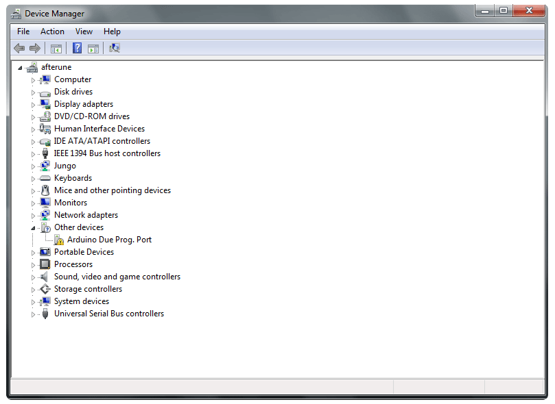
With older versions of Windows, the Device Manager was the primary user interface to address this kind of issue.
Newer versions may offer a legacy user interface to the Device Manager.
 spiral hinge
Oh yeah no, it reads in the Device Manager no issue. I'm currently removing and reinstalling through the board manager
pine bramble
Yeah you may be missing some support in board manager - SAMD oriented stuff.
(or just SAM .. this isn't SAMD)
spiral hinge
I guarantee you that whenever this problem is solved, it will be incredibly simple. It always is.
pine bramble
When I see something I don't understand, sometimes I get into a mode where I can't look at it in a relaxed manner at all. ;)
spiral hinge
Too real. But such is the life of a programmer.
pine bramble
This is my shutdown screen on one of my TinyCoreLinux machines:
http://images6.fanpop.com/image/photos/33400000/Don-t-Panic-ascii-art-33480439-383-300.jpg

aka Don't Panic
spiral hinge
Yeah, I'm still pretty new to electronics, so my project with the Due is meant solely for fun
I've made a game controller before, but now I want to try it with motion detecting
pine bramble
wow - nice page on this:
http://pixelpompeii.blogspot.com/2016/05/textmode-art-roundup-hitchhikers-guide.html
has ascii art source
That Due is a nice unit, judging by the schematic.
spiral hinge
Dang, I was really hoping Device Manager would do the trick. But alas, it tells me that I already have the current drivers needed.
pine bramble
Could be misoperation of the Arduino IDE.
spiral hinge
Quite honestly, I got the Due for more ports and cause I remember Unity being really fussy with the Uno, in terms of supporting outside controllers.
A print statement broke my whole program last time.
pine bramble
Arduino culture is suggestive of ease of use, but all they're trying to do is make it a little easier for beginners to interact with these systems.
Once it's up and running the feeling that you got a bad deal goes away, some. ;)
spiral hinge
Yeah, then 90% of the issues lies in the wiring
pine bramble
Get in the habit of frequently shutting down the Arduino IDE between uses.
Whenever your work is saved, is good.
spiral hinge
Will do
I'm reinstalling it and all the drivers again
pine bramble
If it hasn't been reinstalled in a few months, the problem may just go away when it's all installed again.
Every once in a while, reinstallation makes things worse - for obscure reasons.
spiral hinge
Again, I'm sure it's something really minor, but at this point, I'm just very curious to know what it is
pine bramble
In Linux I know how to log all those error message (and just status or warning messages) to disk, so I can look through them for stuff I wasn't aware of.
spiral hinge
I would love to use Linux more on my machines, but because I do game and art development, Linux is not quite there yet in either realm. It's a shame, there's so many better commands and less overhead to deal with.
pine bramble
You can probably just highlight the stuff in the lower divided window (where the orange error messages print) and copy that to a plaintext file.
(Control A, Control C might work in that window, after highlighting any word in that window).
Control V, I think, pastes (to some other window such as a word processor or plain text editor).
spiral hinge
Yeah, Ctrl+V is paste
pine bramble
Especially once it's working correctly, it's good to have a copy of what things look like in the error window, when there aren't any errors. ;)
spiral hinge
I reinstalled the IDE, and I'm doing my last tests for the time being. If it doesn't work here, I'm gonna call it quits for the next couple of hours and just work on something else in the meantime.
pine bramble
a pilot friend, who's done flight instruction, insists: You cannot force knowledge. ;)
spiral hinge
The answer will come soon enough, but this little issue is quite puzzling to me.
I mean, at least the ports aren't switching at random anymore, I can take solace knowing that's no longer an issue. And a fresh install of an IDE hasn't hurt anyone yet.
pine bramble
COM4 is probably going to be used.
spiral hinge
Yeah, the Programming Serial port is officially on COM4
The Native USB one is on COM9
pine bramble
0x3f8, 0x2f8, 0x3e8, 0x2e8 were the original addresses for COM1, COM2, COM3 COM4 respectively. Those were USART based serial.
spiral hinge
Yeah, I can see that if I continue to plod on this anymore right now, I'm gonna get the same results.
Thank you for helping me get at least this far. I'm gonna sit on this for a little bit and try again, a number of hours from now.
pine bramble
You're welcome. Time away from it lets the experiences you already have, sink in. ;)
 woeful gull
Hi.
So i need help adding a buzzer to this
const int pinLaser = 6; // output signal pin of laser module/laser pointer
const int pinReceiver = 7; // input signal pin of receiver/detector (the used module does only return a digital state)
void setup() {
pinMode(pinLaser, OUTPUT); // set the laser pin to output mode
pinMode(pinReceiver, INPUT); // set the laser pin to output mode
digitalWrite(pinLaser, HIGH); // emit red laser
Serial.begin(9600); // Setup serial connection for print out to console
}
void loop() {
int value = digitalRead(pinReceiver); // receiver/detector send either LOW or HIGH (no analog values!)
Serial.println(value); // send value to console
delay(1000); // wait for 1000ms
}
How do I add the buzzer code to this?
i want to make it so when the lazer hits the reciver, the buzzer starts to turn on.
help asap
 buoyant dagger
Write an if statement to see if the input measured from the pin is high or whatever the laser sensor would send out when a laser hits it
Then if that's true, look at the buzzer examples (i'm new to arduino but as a programmer I know how to get what you intend)
Check out the piezo buzzer examples.
At the very least, you could also send a current to the buzzer through an analog pin or something
if (value > something) { buzz();}
woeful gull
hmm
so
what do you mean by
value and something?
@buoyant dagger
im a complete noobie
i know when the laser hits the reciver
its value changes to 1?
if (1 > 0) { buzz();}
}
??
bro im confused
lmao
ok wait i did something
void loop() {
int value = digitalRead(pinReceiver); // receiver/detector send either LOW or HIGH (no analog values!)
Serial.println(value); // send value to console
delay(1000); // wait for 1000ms
if (value = 1) {tone(buzzer, 1000);
}
but it says that expected '}' at end of input
buoyant dagger
Uy
Uh
Let's see here
You need another "}" try putting it right after the semicolon on the tone(buzzer, 1000);
@woeful gull
woeful gull
uh
oh wow
ok
so
its buzzing.
but
i want it so
so the reciver when it-
hold on
if i change this
buoyant dagger
Be the engineer
 cedar mountain
You want "== 1" instead of "= 1" for a comparison.
woeful gull
oh
thanks
it keeps buzzing
hmm
even though the laser isnt touching the reciver
buoyant dagger
Okay so
woeful gull
wait
cedar mountain
You might need to turn off the buzzer when value is not 1.
woeful gull
hmm
woeful gull
when the laser is hit with the reciver, the buzzer turns on and doesnt turn off
You might need to turn off the buzzer when value is not 1.
@cedar mountain
gppd odea
good idea
so another statement
where it turns off?
buoyant dagger
So if (value == 1) { do something} else { buzzer turns off }
Also I would put the if and else statement before the delay
So the reaction is immediate
woeful gull
if (value == 1) {tone(buzzer, 1000) else (tone(buzzer, 0);}
coding is harder then i thought
woeful gull
im following ur syntax
buoyant dagger
I'm on mobile rn heres my try:
Imma send it out line by line so u know how it should look
if (value == 1) {
  tone(buzzer, 1000);
} else {
  tone(buzzer, 0);
}
There
 north kelp
Pro-tip, @buoyant dagger You can use backticks to format code here, like this:
```cpp [some code] ```
buoyant dagger
Oh yeah, I forgot how to use markup code tho
woeful gull
interesting.
buoyant dagger
Oh wait nvm u just say like cpp or Java or smt right after the ticks
north kelp
if (value == 1) {
tone(buzzer, 1000);
} else {
tone(buzzer, 0);
}
Thanks
woeful gull
The buzzer turns on, when the laser isnt touching, the nwhen it is touching it just makes a higher pitch
buoyant dagger
Okay
woeful gull
leme try that code obove
buoyant dagger
So make sure ur tone function is used correctly
woeful gull
hmm
buoyant dagger
See if there are other methods
woeful gull
WAIT
@north kelp when it hits, it turns on. But doesnt turn off.
tone(buzzer, 0);
}
this tone thing
might be a problem
north kelp
You can also use noTone() to turn a tone off.
north kelp
Here's the official reference on tone()
https://www.arduino.cc/reference/en/language/functions/advanced-io/tone/
The Arduino programming language Reference, organized into Functions, Variable and Constant, and Structure keywords.
north kelp
You put the pin number in noTone().
buoyant dagger
Gl mishal im off
buoyant dagger
My pleasure
woeful gull
noTone(9)
north kelp
Keep playing, @woeful gull ! I have to remember to be happy when I get things sort of working, then working a little bit better. That's all part of the process.
north kelp
This is what all of us do on projects; first code, even from very experienced programmers, rarely works the first time exactly as expected.
Also, when I get something working, I save a copy of it somewhere, so I can go back to a working version if my code gets complicated, and for future me, who will forget how tone() works. 😄
woeful gull
that would be really helpful
im poroud of my self
i did a thing
and i finished the thing
north kelp
Congrats, @woeful gull!! You're coding, debugging, and making something that actually works!
woeful gull
I am proud of my self for the first time
the nottone thing helped me a lot
so thanks for that
north kelp
When I first started doing this a few years ago, I started to understand how some of my kitchen appliances worked, and how they had little microcontrollers like Arduino doing very similar things.
I suddenly felt like I had appliance X-ray vision.
woeful gull
Lol
You just discovered a new superpower by looking into a toaster
ok its offical
im going to be a coder when i grow up
if thats a thing
north kelp
@woeful gull More cool projects to inspire you in the Adafruit Learning System. Some are very simple, and a good place to start.
https://learn.adafruit.com
woeful gull
thanks 🙂
oo
would it be good if i added things to this?
like buttons
so i can learn
more
north kelp
yeah, sure!
north kelp
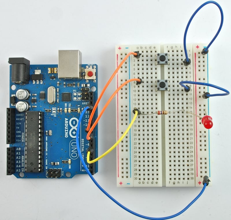
This will get you started with buttons:
https://learn.adafruit.com/adafruit-arduino-lesson-6-digital-inputs
 north stream
I've found I learn more when I mess the code up than when I get it right the first time.
north kelp
You'll be answering that button question for someone else starting out, at some point. 😄
woeful gull
🤣
north kelp
@north stream I also learn more by typing rather than copy/pasting.
north stream
Not only is knowledge not lost by sharing it, we learn more by teaching.
north kelp
Part of how I stay sharp, especially between hardware projects, is by helping others out on theirs. Plus, people will ask questions that I have an intuitive answer for, but answering makes me feel a duty to find what the best answer is. So yeah, sharing deepens my understanding.
woeful gull
bro
this makes way more sense now
wait
whats this
exit status 1
expected initializer before 'pinMode'
north stream
Seems like the compiler got confused. Maybe a syntax error in (probably) setup()?
 raven flame
I've been coding for 33years, i still get syntax errors left right and center 😄
difference is it takes 3 seconds to clean it up not half an hour
north stream
Knowledge comes from experience, and experience comes from mistakes.
 odd fjord
Experience is being able to recognize your mistakes when you make them again 😉
raven flame
if mistakes are required for learning and getting better; then they can't be mistakes.
north stream
"From the ashes of disaster, grow the roses of success!" – Chitty Chitty Bang Bang
raven flame
i blown up leds testing circuits :D
now i have some LEDs i care about i know how not to blow them up
sacrificial learning LEDs ; not mistakes lol
north stream
So in their case, LED could be "learning emitting diode"?
pine bramble
I'm never wrong. I thought I was, once -- but I was mistaken.
woeful gull
could I get a help with a code that turns on a laser
north stream
You were working on that before, what happened?
woeful gull
it just back fired
I keep getting errors
and I’m not sure how to@fix them
and couldn’t find any other way around it
north stream
What errors are getting?
 deft frost
anybody know where I can download the I2S library for arduino, just for andruino board so should be supported.
i cant find anywhere.
north stream
The plain stock Arduinos with AVR CPUs don't have the hardware to support I2S. The more powerful SAMD21 Arduinos (Zero, MKRZero, MKR1000) can.
north stream
No, that has the same AVR CPU as the other basic Arduinos.
woeful gull
Something about the void setup not being right, int wrong and multiple things
north stream
Hmm, sounds like a syntax error before your setup() declaration
north stream
There's probably a garbage character or typo at the top of your sketch that is confusing the compiler so when it gets to setup() it doesn't know what's going on any more, so it just complains about "void setup" and "int" and stuff that's probably fine otherwise.
woeful gull
??
well it looks all good to me
leme check if i have any typos
now its complaining about this
a function-definition is not allowed here before '{' token
north stream
Scroll up, it looks like something before that is confusing it.
 twin ginkgo
sorry for long reply got caught up with stuff and could not get back but how do i upload sketches to the atmega
im using a metro board
 inland crag
metro 328?
twin ginkgo
i think so one sec
inland crag
metro m0 and metro m4 aren't using the atmega chip, only 328 is.
twin ginkgo
yeah metro 328
inland crag
ok, it's designed to be compatible with an arduino uno so you can probably just select that in the arduino boards menu
twin ginkgo
but the atmega chip im using on a breadboard for my project so i can release the metro from the project
inland crag
oh I see
twin ginkgo
and just connect the scl and sda to the project
with the crystal and copasitors
ofcourse
inland crag
you might need an external programmer or an arduino with a socket for a 328
twin ginkgo
i have the tx and rx connected with the reset and power and ground
inland crag
or this might work https://www.instructables.com/id/Program-ATmega-328-Using-Arduino-Arduino-As-ISP/

Instructables
Program ATmega 328 Using Arduino (Arduino As ISP): Arduino is nowadays an easy tool for e-hobbyists .As an open platform and a "ready to use" circuit, everyone follows various arduino boards for realization of embedded designs. But sometimes it is difficult and unaesthetic to...
twin ginkgo
is there an option to send the script that way
i tried but its having an upload error
inland crag
I tried something similar once, I think I wound up using avrdude directly and had to modify some of the parameters
twin ginkgo
avr?
inland crag
avrdude is the programmer arduino uses under the hood
twin ginkgo
oh
inland crag
you could try "export binary file" in arduino and then this in cmd, replacing the .hex filename with yours and the COM port with your arduino COM port.
avrdude -p m328p -P COM4 -c avrisp -b 19200 -U flash:w:release.hex
I think when I tried using arduino as isp it was still doing -c arduino instead of -c avrisp
maybe you can just change the programmer settings in arduino
idk
twin ginkgo
idk well i have to go to bed but thanks for the help hope i can get it
cedar mountain
Have a look at the Bluefruit Feather M0. Looks like it has 10 analog inputs, so that would be enough. https://www.adafruit.com/product/2995

Feather is the new development board from Adafruit, and like its namesake it is thin, light, and lets you fly! We designed Feather to be a new standard for portable microcontroller ...
 sage anvil
heya does anyone have the pinout for one of these guys
or how i could access the 4 pins on the bottom
cedar mountain
Looks like this has the pinout: https://wiki.dfrobot.com/Beetle_SKU_DFR0282
wiki:As the smallest Arduino Leonardo, it enjoys similar powerful functionalities. Beetle aims to solve problems of low-cost controller, ease-of-using properly, and to provide a low cost solution for disposable projects, such as DIY projects, worksh

 surreal pawn
why? is flipping the board over hard?
pine bramble
@sage anvil Solder directly to those pins, or maybe solder a connector to them, or use pogo pins.
(the latter implies a holding jig)
sage anvil
i was planning on attaching the whole thing to a pcb so if i am i think ill just flatten some pins and solder em on
pine bramble
The square pad is probably PIN1
sage anvil
also do u know if its possible to make a USB pass through on a pro micro?
pine bramble
Not sure what that means.
sage anvil
uh
im makin a small keypad with the pro micro and its got the RX and TX pins so can i send those to another USB device and have that send signals to the computer through the pro micro
pine bramble
http://adafru.it/1456 is a means to 'tap' into all wires of typical USB stuff (except the new USB-C).
That's a terse sentence you just typed similar to what I'd type if explaining something to myself. ;)
I haven't parsed it yet. ;)
Sounds impossible loopback to me offhand but a schematic (hand drawn and photographed with a smartphone camera and uploaded here) could help clarify.
'send those' is particularly unclear to me. ;)
Sounds like this: the pro micro (whatever that is) talks to a host PC via USB.
It listens on its USART (TX/RX pair) from 'something else'.
That something else isn't USB at all, it is 'serial' (it's another USART or a bitbanged GPIO from some off-board resource).
I just don't see the role of the USART in this, as a keypad (simple DC interconnect switch array) is 'read' with the GPIO of the same microcontroller that talks USB to the host PC.
You can (of course) split those functions out, and have some second MCU reading its GPIO port, which is fed information by the keypad in the form of completed DC circuits.
sage anvil
i only just got started with anything to do with arduinos so im not very good with like any of these things
but basically i want something similar to this,
this is on a corsair k95
u can plug in any other usb device and itll connect it to ur computer through the same cable
pine bramble
That sounds like a 'USB hub' to me.
sage anvil
yea pretty much
pine bramble
As if that thing (whatever it is) has a USB hub inside it, perhaps in addition to (itself) 'being' a keyboard. Apple does (or did) this on its USB keyboards (the Apple keyboard I had also had a USB hub built into it).
You don't want to innovate a USB hub as a beginner's project. ;)
sage anvil
yea prolly not xd
pine bramble
USB is really hard to do from scratch.
sage anvil
might just try to find a small usb hub and stick it in there
pine bramble
So: some Adafruit target boards already act as a mouse or keyboard, in one of the three available USB 'modes'. The other two modes are a) talk back and forth like a serial terminal's conversation, and b) mass storage, like a thumb drive.
There might be a very tiny USB hub on the market, without physical connectors (just solder pads) that'd fit.
But if you just want 'a home brew keyboard' that plugs into a host PC, several Adafruit targets can do that.
They behave the same as your garden variety $15 keyboard from an office supply store does.
sage anvil
oh its not a full sized keyboard, its just 6 buttons connected to the pro micro to use as macros for some stuff
pine bramble
Right. I think any SAMD board can do that, and the ones that have lots of GPIO pins can simplify the design.
ItsyBitsy M0 is probably a good choice, or if there's room, Metro M0
You just need perhaps 6 GPIO port pins to work with (again for simplicity's sake).
1 2 4 .. can do it in three bits if you're clever, I think.
(three GPIO pins)
Since that provides for 8 different bit patterns: 000 through 111 (= 7).
It's just easier to dedicate a GPIO pin to one button and be done with it.
pine bramble
Could be three weeks from now, or never, or some time interval between those, but probably not under three weeks of exposure to these ideas. ;)
I should add: without the USB to host PC requirement, you can read an old IBM PS/2 style keyboard using just two pins and a fairly simple program running on just about any microcontroller you'd be interested in working with.
It's quite nice to have a QWERTY keyboard connected to a chip half the size of your fingernail, and 'talk' the half-fingernail chip, successfully, using a ful keyboard.
deft frost
@north stream i still dont understand why there isn't an I2S support for basic Arduinos. Is it not just decoding the digital signal. Or just nobody bothered to make it.
north stream
My understanding (which may well be wrong) is that the I2S protocol works at high clock speeds (like 12MHz) which are too fast to implement in software, and require hardware support to generate, and the base Arduino CPU (the ATmega328 AVR chip) doesn't have that hardware. Additionally, I2S usually moves large amounts of data quickly, and the AVR chip doesn't have the memory resources to keep up with that kind of sustained bandwidth.
deft frost
how can I check if nrf52840 has hardware support for I2S at least in hopes that software support will come out eventually?
surreal pawn
read the datasheet
odd fjord
@deft frost fyi there is some information on the status of I2S for Circuitpython here <https://github.com/adafruit/circuitpython/issues/1035.
deft frost
mhmm not much is on that thread
does the fact that I2Sout.h I2Sout.c was implemented imply I2Sin can be made too
cedar mountain
Yeah, the nRF52840 datasheet does say it can do I2S, both transmit and receive, master and slave.
deft frost
can you link me the datasheet if you dont mind, thank you.
cedar mountain
But really, it is the first result: https://infocenter.nordicsemi.com/pdf/nRF52840_PS_v1.0.pdf
 elder hare
hmmm why is the animation "lagging" :/
Test :
1 Ring = Smooth
2 Ring = Smooth'ish
3 Ring = Lagg
4 Ring = even more lagg
   static void Run() {

     // Current Millis Time
     unsigned long curtime = millis();

       for (int Index = 0; Index < 6; ++Index) {

         // Check Current Time against Strip Array Time and update accordingly
         if (curtime > ARRAY_STRIP_SETTING[Index].lastUpdate) {
             ARRAY_STRIP_SETTING[Index].lastUpdate = curtime + ARRAY_STRIP_SETTING[Index].Delay;

           // Check Strip Array Current Pattern and switch accordingly
           switch (ARRAY_STRIP_SETTING[Index].ActivePattern){
                   case 1:          SolidColor(Index); break;
                   case 2:        TheaterChase(Index); break;
                   case 3:        RunningLight(Index); break;
                   case 4:               Cylon(Index); break;
                   case 5:             Mitosis(Index); break;
                   default: break;
           }

             // Move the pattern in the direction choosen and increment Array Index by 1
             Function::Increment(Index);

              }

       }
   }
every ring runs the "Theather Chase" animation
north stream
It might help to split your code, so there's one routine for updating the pattern to be displayed, and another to iterate through the patterns.
I'm guessing the Increment() function is what makes the pattern animate, a step at a time?
If you had a separate loop to call that (that doesn't have to do all that other work) it might work more smoothly
elder hare
@north stream yes Increment() is the animator 🙂
north stream
Maybe try making separate code paths: only call the active pattern when you get a pattern update, and only call Increment() when it's time (I'd also precalculate the times)
elder hare
did you see the 3 sec video i sent?
north stream
I'm at work. Can't watch videos.
elder hare
arh :/ i used my phone to show 1 ring animation vs 4 ring animation and the lag
north stream
What happens if you just remove/comment out the switch statement?
elder hare
then it doesn't know what pattern to run
north stream
You said "every ring runs the "Theather Chase" animation". Maybe set each one once, then run the patterns.
I don't know enough about the code to say for sure, but calling those routines over and over could be doing a bunch of work that's unnecessary and slowing down your updates.
elder hare
yea i have set all rings to Theater Chase (that is number 2)
     ARRAY_STRIP_SETTING[3].ActivePattern = 2;
     ARRAY_STRIP_SETTING[2].ActivePattern = 2;
     ARRAY_STRIP_SETTING[1].ActivePattern = 2;
     ARRAY_STRIP_SETTING[0].ActivePattern = 2;
in the setup
north stream
So try having one for loop (in the setup) do the switch statement to set the active pattern, and a separate one (in loop) that just checks lastUpdate and calls Increment() if it's time
elder hare
that would not work as im making it so that im able to switch pattern via my python script
 trail wing
Anyone worked with PID and arduinos?
north stream
A little
trail wing
I have a arduino code to control a conveyor. 10 m/M max. And I'm using the PID-regulator library by Brett Beauregard for arduino. However, for some reason. Output is set 2 times per second and feedback is read 20 times a second.
However, I've found some decent values by trial and error, but occationally, the output drops to 0 and occationally it jumps to the double... I have no idea why
Its otherwise stable except those few times
north stream
That is odd. I have a lot of respect for Brett and his library.
That would be a system with some lag, but not as much as (say) a liquid tank heater.
trail wing
Admittedly, my MV is not exactly stable, +-0.2, but I cant get why it jumps occasionally. roughly once every 5 seconds
north stream
I wonder if the output to control is really nonlinear (as in maybe the conveyor drive doesn't respond to its control signal with a linear speed ramp), or you've happened on a weird local maximum in the tuning parameters.
What's MV?
trail wing
Measured value.
north stream
Ah, that could introduce some noise into the system. If the inaccuracies happen to resonate with your loop, it could cause some odd effects.
trail wing
I'm using the same scale for SV and MV(PV), also for output. output is post-scaled to what the Frequency Inverter expects
north stream
Ah, like a VFD drive?
trail wing
Yeah
north stream
That seems like it would be really linear, unlike PWM control of a DC motor or similar.
trail wing
I'm pondering on switching to Analog control value so that I can update the value quicker. Modbus over RS485 is not exactly fast
10ms for each packet makes for very limited bandwidth with multiple drives
north stream
Yeah, it's a sampled data system without real time reaction: a recipe for oscillations
trail wing
Fun thing is, only the Output on the display oscillates. Since the VFD only gets its value updated 2 times per second, it never reacts to those weird oscillations
Also, the VFD have internal ramp up and down. so the update in Output takes a while to reach its SP, but not counting those weird jumps. Its pretty stable
north stream
Hmm, that might paradoxically make it worse
trail wing
I know, I could change the ramp times to virtually 0... 😄
north stream
That might be informative
trail wing
The VFD have an internal PI regulator. But it have no "jitter" compensation
So I moved to external PID instead
north stream
And it still won't behave? How frustrating.
trail wing
Going to try to move the encoder to the shaft of the drive roller instead of measuring the actual belt speed, to see if I cant get more stable values
north stream
I'd be tempted to instrument things. Maybe old school, have PWM outputs for the internal state variables driving ordinary analog meters, which are great for showing trends and reactions in a way that's easy to mentally follow.
trail wing
If the values wont get more stable, then its the Arduino not having enough CPU to keep up with everything 😄
Yeah, perhaps... Will try more another day. Sleepy time! \o/
north stream
Hmm, good point. You can probably round up a faster CPU and try that, but it seems like your system has enough delay that infrequent updates would be fine (unless they formed a phase shift oscillator)
trail wing
Part of me wants to make a Fuzzy regulator. But I'm too lazy
north stream
That's a magic black box to me.
trail wing
Same here
north stream
Amusingly, I'm going to be building a conveyor with feedback soon, but I'm hoping that my simple use case won't produce a bunch of the kinds of issues you're seeing.
trail wing
I know my teacher at school had a matrix of 5 by 5 values. I know one axis was "control error" and the other "current value"... but how the magic behind which box to select worked... dunno 😄
Oh well, nini
And nice, hope you have better luck than me
north stream
Thanks!
 thorny kayak
oh got some stuff in the mail today...arduino etc. but, how can I power this LED strip with this usb power bank?
cedar mountain
Easiest way would be to sacrifice a USB cable. Cut off an end and strip the wires... the 5V/ground lines are usually pretty obvious.
buoyant dagger
Would you say that an i2c arduino to another microcontroller communication is very fast
Like if I have a bunch of processes to run would it be efficient to i2c several microcontrollers and split the workload and just parse the data through each other if needed
cedar mountain
I2C is not particularly fast... base speed is 100 kbps on a shared bus, though you can clock it faster. Generally rather than trying to do microcontroller multi-processing, you'd probably be happier using one more powerful CPU.
north kelp
@buoyant dagger It really depends on the size of the data, and the speed of computation. What's the use case? Can you give us an idea of what the data are, and what processing you'd like to do?
Would it make sense to instead send the data, over wire or wirelessly, to a phone, PC, or Raspberry Pi?
buoyant dagger
Well this is just a hypothetical, I was thinking about it for fun since you could stack up on a bunch of like cheap ESP8266s
I was reading an article about arduino or raspberry pi and they basically said if what you want to do has more than two "ands" then to use a pi
sage anvil
@thorny kayak depends what type of LEDs they are, theyre usually 12V and occasionally 5V
raven flame
@trail wing if you're getting intermittent doubling and zeroing of your voltages; it sounds like one of your signals is phase shifting out of sync; creating constructive and destructive interference.
elder hare
im trying to turn (OFF) ON / OFF on each strip (total of 4) but they just stand there flashing REALY fast all at the same time, what am i doing wrong?
(arduino - nodeMCU - neopixel - WS2812B)
       // Loop through all the bottles
       for (int Index = 0; Index < 4; ++Index) {

         int hue;

         if(Index == 0) {
           hue = 96;
         } else if(Index == 1) {
           hue = 0;
         } else if(Index == 2) {
           hue = 224;
         } else if(Index == 3) {
           hue = 32;
         }

           fill_solid(Strip[Index], NUM_LEDS_PER_STRIP, CHSV(hue, 255, 0));
           FastLED.show();
           fill_solid(Strip[Index], NUM_LEDS_PER_STRIP, CHSV(hue, 255, 255));
           FastLED.show();
           fill_solid(Strip[Index], NUM_LEDS_PER_STRIP, CHSV(hue, 255, 0));


       }
Hmm, you have no delay and a missing .show().
elder hare
there is a delay 🙂 missing show? on the last one?
north stream
If you felt like it, you could do hue = 32 * ((1 << Index) - 1);
Yeah, there's no show() after the last fill_solid(). I don't see a delay anywhere.
 wind pond
What does this error code mean
 rigid walrus
I’m trying to use a MAX31855 with a k type thermocouple. My output stops at “internal temp =“ and then just hangs. Having trouble figuring out what might be causing it.
`/***************************************************
This is an example for the Adafruit Thermocouple Sensor w/MAX31855K
Designed specifically to work with the Adafruit Thermocouple Sensor
----> https://www.adafruit.com/products/269
These displays use SPI to communicate, 3 pins are required to
interface
Adafruit invests time and resources providing this open source code,
please support Adafruit and open-source hardware by purchasing
products from Adafruit!
Written by Limor Fried/Ladyada for Adafruit Industries.
BSD license, all text above must be included in any redistribution
****************************************************/
#include <SPI.h>
#include "Adafruit_MAX31855.h"
// Default connection is using software SPI, but comment and uncomment one of
// the two examples below to switch between software SPI and hardware SPI:
// Example creating a thermocouple instance with software SPI on any three
// digital IO pins.
#define MAXDO 3
#define MAXCS 4
#define MAXCLK 5
// initialize the Thermocouple
Adafruit_MAX31855 thermocouple(MAXCLK, MAXCS, MAXDO);
// Example creating a thermocouple instance with hardware SPI
// on a given CS pin.
//#define MAXCS 10
//Adafruit_MAX31855 thermocouple(MAXCS);
void setup() {
Serial.begin(9600);
while (!Serial) delay(1); // wait for Serial on Leonardo/Zero, etc
Serial.println("MAX31855 test");
// wait for MAX chip to stabilize
delay(500);
}
void loop() {
// basic readout test, just print the current temp
Serial.print("Internal Temp = ");
Serial.println(thermocouple.readInternal());
double c = thermocouple.readCelsius();
if (isnan(c)) {
Serial.println("Something wrong with thermocouple!");
} else {
Serial.print("C = ");
Serial.println(c);
}
//Serial.print("F = ");
//Serial.println(thermocouple.readFahrenheit());
delay(1000);
}`
I'm using a thermocouple from phidgets...it's still a k-type though.
pine bramble
Put in more print statements so you can find exactly where it stops.
I would put the first one right after the last message that does print.
(right after the first line after it, I mean .. otherwise it's redundant information)
rigid walrus
void loop() { // basic readout test, just print the current temp Serial.print("Internal Temp = "); Serial.println(thermocouple.readInternal()); Serial.print("readInternal just happened");
Something like this?
pine bramble
yeah
rigid walrus
Thanks
pine bramble
Unless there's a specific reason why it would fail, that is generally a good technique for spotting code structural errors and routines that never return control to program flow.
rigid walrus
Welp, didn't see that printed, so something must be up with Serial.println(thermocouple.readInternal()) ?
pine bramble
Yes. I would break that down -- do the read separately from the print.
a = this(); Serial.println(a);
I usually only print strings so I don't know what happens during printing of other types.
rigid walrus
where this() is the thermocouple.readInternal() function?
pine bramble
Yes. I don't want to type out supercalifredg(); when this(); is a good stand-in for what I was saying. ;)
rigid walrus
hahaha, got it
elder hare
@wind pond you have not declared the variable "lcd"
rigid walrus
It looks like arduino might want me to define "a" outside the loop?
Serial.print("Internal Temp = "); a = thermocouple.readInternal(); Serial.println(a); Serial.print("readInternal just happened");
'a' was not declared in this scope
pine bramble
void foo(void) {
    int a = 0;
    a = this();
    Serial.println("just read a and exercised the this(); function");
}
Some solid teaching here, nis. Thank you.
pine bramble
all you want to know is what happens when this(); gets called.
As a Forth language programmer, I'm trained to 'factor' my code. Try to think what each element does, and can it be broken down further.
Top down; bottom up; middle out.
rigid walrus
All my programming comes from R, so this is a bit of a different ballgame.
pine bramble
C (and C++ I am told) is lingua franca for MCU programming .. it's really hard to avoid it entirely.
rigid walrus
Serial.print("Internal Temp = "); int a = 0; Serial.println("just initialized a"); a = thermocouple.readInternal(); Serial.println("just defined a"); Serial.println(a); Serial.println("just printed a");
it's not printing "just defined a"
So...something's breaking in that function. Cool.
pine bramble
Turn on all warnings in the IDE.
I take it you're compiling then uploading to a target board.
Serial Monitor or somesuch is used to look at the printed messages.
Put in a good hefty delay before you call the thermocpl thing
Maybe it doesn't have time for the hardware to settle.
rigid walrus
Right. I'm compiling in Arduino IDE and uploading to a Metro 328
pine bramble
What protocol is it talking over? SPI? i2c? aka 'physical'
rigid walrus
SPI
In file included from /Users/ajohnson/Documents/Arduino/serialthermocouple/serialthermocouple.ino:18:0: /Users/ajohnson/Documents/Arduino/libraries/Adafruit_MAX31855_library/Adafruit_MAX31855.h:49:32: warning: passing NULL to non-pointer argument 1 of 'Adafruit_SPIDevice::Adafruit_SPIDevice(int8_t, uint32_t, BitOrder, uint8_t, SPIClass*)' [-Wconversion-null] Adafruit_SPIDevice spi_dev = NULL;
pine bramble
I have no idea what library or class that thermocouple thing is from.
pine bramble
oh I didn't know afruit had a lib for those ;)
what's line 18 in the .ino look like
rigid walrus
#include "Adafruit_MAX31855.h"
pine bramble
I don't think that's it because it compiles and uploads okay.
The newer compiler is very picky and a lot of code has to be rewritten to satisfy its new hunger.
(technically it's not the compiler that's new; something fundamental changed that makes it look like a newer, picky compiler is the present IDE environment).
rigid walrus
hm
I mean, I would guess that spi_dev = NULL is probably just saying that I don't want development mode? Or...something?
pine bramble
I didn't really process it in my head yet. ;) I was going with 'placeholder' though.
I'm thinking this has to be in the program:
Adafruit_SPIDevice spi_dev = myfoobar;
Whatever the example has.
rigid walrus
`#include <SPI.h>
#include "Adafruit_MAX31855.h"
// Default connection is using software SPI, but comment and uncomment one of
// the two examples below to switch between software SPI and hardware SPI:
// Example creating a thermocouple instance with software SPI on any three
// digital IO pins.
#define MAXDO 3
#define MAXCS 4
#define MAXCLK 5
// initialize the Thermocouple
Adafruit_MAX31855 thermocouple(MAXCLK, MAXCS, MAXDO);
// Example creating a thermocouple instance with hardware SPI
// on a given CS pin.
//#define MAXCS 10
//Adafruit_MAX31855 thermocouple(MAXCS);`
pine bramble
rigid walrus
This is all there is before the setup() and loop()
pine bramble
I don't usually think unless it's absolutely necessary; that just interrupts my brain's pattern-matching skills ;)
'find the pretty thing that looks a lot like the other pretty thing'
Probably time to review all wiring concerns. The code assumes specific pins are used.
This is software SPI (hardware SPI only specified chip select; soft SPI also specifies two other pins).
(because hardware SPI would always be on specific pins and isn't user-configurable, iirc)
rigid walrus
Yeah, I rewired the breadboard and now it's spitting an endless string of "8X31X31X31X31X31X31X31X318X31X". I had a discussion post on Adafruit forums earlier this month that prompted me to learn to solder so I could actually do this. I've posted an update to that forum post. We'll see what happens.
pine bramble
what gets me is that it never returns at all. That's half-unexpected.
rigid walrus
Something in the initial wiring wasn't working 😬
pine bramble
if it's not halting that may be progress (not sure).
rigid walrus
But now it's screaming bloody murder
I really appreciate all your help, nis. Thanks again.
pine bramble
hehe you're welcome.
I don't know what would be showing that string you typed 8x31x stuff
rigid walrus
I know, it puzzled the forum adafruit employee too
pine bramble
Is that a Serial.print() type of output on SerialMonitor?
rigid walrus
It looks like it's just freaking out at Serial.println("MAX31855 test");
I think it's printing the X318 part endlessly
The larger block of code is `void setup() {
Serial.begin(9600);
while (!Serial) delay(1); // wait for Serial on Leonardo/Zero, etc
Serial.println("MAX31855 test");
// wait for MAX chip to stabilize
delay(500);
}`
pine bramble
Well put in a really long delay to slow it a lot.
You want to know what is emitting that strange x318 string
Basically what I do is 'ruin' the code by commenting out almost all of it, so I do this on a copy of the code (so I don't have to undo a lot of edits made for troubleshooting).
Then reintroduce code and see what happens. Which essentially simulates construction of the program for the very first time, as if you were the original author of the code.
It really helps a lot if you have mad github skills at that stage, as revision control makes things that happen /over time/ understandable when viewed /frozen in time, later/.
wind pond
@elder hare how could I declare the variable
wind pond
#include <Wire.h>
#include <LiquidCrystal_I2c.>
LiquidCrystal_I2C lcd(0x27,20,4); // set the LCD address to 0x27 for a 16 chars and 2 line display
int measurePin = 0; //Connect dust sensor to Arduino A0 pin
int ledPower = 2; //Connect 3 led driver pins of dust sensor to Arduino D2
int samplingTime = 280;
int deltaTime = 40;
int sleepTime = 9680;
float voMeasured = 0;
float calcVoltage = 0;
float dustDensity = 0;
void setup(){
lcd.init(); // initialize the lcd
lcd.init();
// Print a message to the LCD.
lcd.backlight();
lcd.setCursor(0,0);
lcd.print("Raw Signal Value: ");
lcd.setCursor(0,2);
lcd.print("Voltage:");
lcd.setCursor(0,3);
lcd.print("Dust Density:");
pinMode(ledPower,OUTPUT);
}
void loop(){
digitalWrite(ledPower,LOW); // power on the LED
delayMicroseconds(samplingTime);
voMeasured = analogRead(measurePin); // read the dust value
delayMicroseconds(deltaTime);
digitalWrite(ledPower,HIGH); // turn the LED off
delayMicroseconds(sleepTime);
// 0 - 5V mapped to 0 - 1023 integer values
// recover voltage
calcVoltage = voMeasured * (5.0 / 1024.0);
// linear eqaution taken from http://www.howmuchsnow.com/arduino/airquality/
// Chris Nafis (c) 2012
dustDensity = 0.17 * calcVoltage - 0.1;
lcd.setCursor(1,1);
lcd.print(voMeasured);
lcd.setCursor(9,2);
lcd.print(calcVoltage);
lcd.setCursor(14,3);
lcd.print(dustDensity);
delay(1000);
}
what is rong
what is rong
@wind pond
inland crag
@dull bison #define HallPin A2
 dull bison
@inland crag so i have to redeclare all my variables i wanna use? seems a bit.. not coder friendly
inland crag
that's c for you
dull bison
Is it possible to include your main folder, cuz that seems to take errors away aswel, but i dont know if its good practise
 lilac mountain
why is it "not recommended" to reset millis() as described here? https://forum.arduino.cc/index.php?topic=184596.0
Resetting Millis() to zero, reset clock
cedar mountain
I presume that some libraries will use the timer for internal state, so they'll get confused about how much time has passed between events.
wind pond
what does it mean when arduino ide tells you thare is no such file or directory
 fair reef
It's been over a month that I haven't managed to get access to the SPI flash chip on the Serpente R2 board with the Adafruit SPIFlash library. The board creator and maintainer of the Serpente hardware for Arduino IDE have been unable to help either.
This is as far as we've come, with this output from the flash manipulator:
JEDEC ID: 85
Flash size: 0
Initializing SD card... Card failed, or not present```Is the flash formatted?
buoyant dagger
Is there a limit to how many i2c connections an arduino can have simultaneously
cedar mountain
I wouldn't expect so. Only one can use the bus at a time, so there shouldn't be much that scales. Apart from address limits.
buoyant dagger
Awesome
By the way, does anyone have any info/documentation references to figure out how I can connect my ESP8266 nodemcu to my computer over wifi? I can't seem to find anything specifically for that purpose. Basically my goal is to be able to send data (doubles, ints etc) from the computer to the esp8266 and vice versa
I originally accomplished this over wire by connecting my arduino to the pc with a usb, which by default can send information to the serial monitor
But the issue is I'm using the nodemcu as a way to transfer arduino info to the PC wirelessly
so I can't use the arduino IDE/serial monitor
north stream
I think you'd just send stuff using TCP or UDP. Easiest way might be a simple REST client.
buoyant dagger
I'm not much of a web expert, so I'll look into that stuff
north stream
You can use the "netcat" tool to set up a simple link to play with.
buoyant dagger
Oh dang, this is just what I was looking for
Thanks! Now that mitigates the need to connect it to the arduino ide, and I can just port the data directly to eclipse :D
Actually to make it even faster, I'll just set up a server with eclipse and then have the esp8266 communicate directly with it
netcat is a good tool for testing though so I'll def use it
fair reef
@north stream, the goal is to access the SPI Flash as a FAT filesystem, as is the use of the SPIFlash library. It came properly formatted, with CircuitPython plug'n'play.
The issue is being tracked at https://github.com/technoblogy/serpente-core/issues/1
GitHub
Hello, I'm not very good at this stuff, but I think the current variant.h file lacks the configuration needed to use the Adafruit SPIFlash library.
sage anvil
how would one go about using one of these chips with an arduino actually
would be cool if i could add alot more stuff to one of my lil keyboards
pine bramble
Hi Internet People, is there a way to integrate google assistant/ Alexa into my arduino e.g I ask what the time is or what a word means and it will speak a response back- without using my phone. Also is there a way to create my own version of Alexa with custom responses and a custom voice that I could use in my arduino project as discussed above. In addition to this, I don’t want to use a raspberry pi etc... I just want to use an arduino. Thanks in advance
sage anvil
i know someone who got a custom wake word for alexa but according to him it was incredibly tough and was not worth it
north stream
@sage anvil which chips?
sage anvil
The spi flash ones
north stream
Yes, there are Arduino libraries to talk to them.
pine bramble
@sage anvil thanks, different question: is there a really good tutorial that shows how to use a esp module and relay to make the relay go on or off once it has received data from a website- I don’t want to use Blynk or something like that because I can’t have it as a standalone app
north stream
Received data from a website? Something like a HTTP fetch or REST call, or more like a message queue/pub-sub site, or what?
 charred salmon
Looking at the Feather M0, VBUS says "Absolute MAX 500mA"
Now, looking at the schematics I know that the VBUS pin is a straight line to the USB in with absolutely nothing in between, not even any passive components.
So is the 500mA limit because it's assumed that the port on the other end of the cable will limit to 500mA, or is it because they don't think the traces on the board can handle more?
raven flame
it's more likely to be components blowing out than the pcb traces
as for USB power, it depends what power plug you have; some are limited to 500ma; and the fast charge ones can pump out 2amps.
also depends on the cable; some older USB cables also limit the current to 500ma.
charred salmon
I've got a powerbank rated for 2A output, and if need be can stick on a better cable. I'm just sort of trying to figure out if I'll need to splice a cable to grab the power directly without going through VBUS
I don't think I'll need the whole 2A, but I'm pretty sure I'll at least exceed 500mA
raven flame
if you're using a usb cable on an arduino then it should have all the current limiting things on the board.
charred salmon
Well, according to the schematic, it's a straight connection from the USB to VBUS
Which is why I'm wondering the reason for the stated limit.
raven flame

We also have the 3V pin which has the output from the 3.3V regulator. We use a 500mA peak regulator. While you can get 500mA from it, you can't do it continuously from 5V as it will overheat the regulator.
charred salmon
I'm not going through the regulator though since I'm using a powerbank on the USB.
raven flame
are you trying to power something off the arduino board?
charred salmon
Yes
raven flame
i think in that case you power it from the USB pin; which should bypass the regulator.
charred salmon
That it does, but said pin is listed as 500mA max
raven flame
in that case you'll need to power whatever it is seperately; just make sure the grounds are connected
charred salmon
Yeah. Rather irritating, but I guess better than blowing up the traces.
Or maybe I just tempt fate, and see what I can draw from it, and see what, if anything, blows up when I pull 1A through it.
raven flame
yeah you should definitely not do that 😄
opto-couplers are a great way to isolate power circuits
charred salmon
The Dotstar example sketch pulls 250mA for 10 lights, but I'm not going to have them at full bright.
raven flame
or mosfet
charred salmon
Time to go to microcenter and buy a sacrificial cable.
raven flame
bed time for me g'night
charred salmon
Good night
thorny kayak
okay there has to be a better way to do this
trying to power LED strip with USB
how tf
cedar mountain
The larger red and black wires in the USB cable are almost certainly the +5V and GND.
thorny kayak
so electrical tape to wrap the red and black cables to the 2 coming from the LED strip?
cedar mountain
Well, ideally you'd solder them or at least use wire nuts to make good electrical contact.
thorny kayak
crimper?
cedar mountain
That works too.
 fiery lichen
When I do audio I usually use the sound fx card. What’s the best card and speaker to use to get louder audio without getting power supply switching noise!
*?
pine bramble
Hi guys can someone try to explain some things to me about the code: 1. How does the Byte array work and how is it called. 2. What is the code at the very bottom for for(int I = 0 ... end)

GitHub
Repository of the 7 segment digital clock I made as found on my youtube channel - leonvandenbeukel/7-Segment-Digital-Clock
surreal pawn
the loop sets the color of the corresponding pixel to either black or the specified color depending on if that digit has that segment lit or not
the "segment lit or not" check is what the byte array is used for. the digits 0-9 are positions in the array 0-9 and the "segment is lit" is the "bit is set". 1<<0 evaluates to 1 and corresponds to the least-significant (rightmost) bit. 1<<2 evaluates to 2 the second least bit, 1<<3 evaluates to 4, 1<<4 evaluates to 8 and so-on
the 0b prefix is a way to type in numbers in binary
the segments in a 7-segment have a typical ordering, though they typically use a-g for them

A seven-segment display is a form of electronic display device for displaying decimal numerals that is an alternative to the more complex dot matrix displays.
Seven-segment displays are widely used in digital clocks, electronic meters, basic calculators, and other electronic d...
pine bramble
@surreal pawn thanks for the quick and lengthy response!!!! 😃
surreal pawn
byte numbers[] = {
    //hgfedcba
    0b00111111, // 0
    0b00000110, // 1
    0b01011011, // 2
    0b01001111, // 3
    0b01100110, // 4
    0b01101101, // 5
    0b01111101, // 6
    0b00000111, // 7
    0b01111111, // 8
    0b01101111, // 9
  };
@fair reef Is there some reason not to switch to a supported target board .. one quite similar to the Serpente in most respects?
I thought that issue you posted got very good responses.
Basically @lethal wigeon and Dean Miller have been principle devs on flash in recent times.
hathach posted some strong revisions in early February of this year (which means I have to rework my SPI Flash use cases to conform to those updates).
https://preview.tinyurl.com/spi-ea3ad-3-feb
which is short for
◾
https://github.com/adafruit/Adafruit_SPIFlash
with an additional pointer to the commit
◾
ea3addebe9569
Really basically, you can trace the history of the current code using the git toolchain, or use github.
I haven't found an easy way to trace backwards - I use a combination of tools to know which parent commit to explore, next, on github.
Much easier for me to use gitk for this task. ;)
Commits, most recent to oldest in sequence:
283da21 , 554a99e , 78c0e79 , e1c5e6c , 3d65476 , 5b57404 , ea3adde
for Adafruit_SPIFlash repository wrt these changes. ;)
raven flame
if you're planning to use a 7 segment display i highly recommend 74HC595 (clk/latch/data) to drive it, or HT16K33 (i2c) to drive multiples.
fair reef
@pine bramble, the reason I don't want to switch the target board is because:
- I like the idea of solving something others can make use of
- the Serpente is adorable
- I'm not so rich
north stream
The MAX7219/21 is also an option, but I have a real fondness for the HT16K33 myself. There's also the old school approach of the 7447.
raven flame
is there an easy way to get a crystal frequency to multiply out to 1hz?
north stream
You mean divide? It's normally done with ordinary binary dividers (for example, many real time clock chips use a 32767Hz crystal and divide by 2 15 times)
raven flame
yes 🙂
north stream
What frequency is your crystal?
raven flame
i don't have one yet 😄
north stream
There used to be a chip available that used a common TV color crystal and provided a 1Hz output. Many clock chips will also do so.
There are chips like the CD4040 that have a bunch of dividers in them, as well as fancier chips with programmable dividers, and even fancier ones that can do direct digital synthesis of whatever frequency you like.
raven flame
i was thinking to use a crystal based oscilator to make the seconds blink rather than using arduino code. it'll probably be more accurate
north stream
You certainly can do so. Most Arduinos have a crystal stabilized clock, however.
north stream
I looked up the 1Hz chip, it's the old MM5369, but it's not made any more. However, it's not too tough to build a 32768Hz oscillator and add some dividers.
raven flame
isn't there a more hmm rounded oscilator? 😄
oh nvm; that one divides nicely into 2^N 🙂
north stream
Yes, that's why it's a popular frequency
pine bramble
@fair reef The chip Serpente uses is pretty much the same as the two supported chips in that product line. Just the capacities differ.
https://github.com/adafruit/circuitpython/blob/master/supervisor/shared/external_flash/devices.h#L108
⚫
https://github.com/adafruit/circuitpython/blob/master/supervisor/shared/external_flash/devices.h#L126
I wouldn't even bother with a datasheet.
On the other hand, a proper github repository showing all your work would be possibly quite useful.
sage anvil
Hey is it possible to attach an sd card breakout board to a pro micro
cedar mountain
Should be able to, as it has a SPI port. However, SD Cards are generally not 5V-compatible, so you'll either need the 3.3V version of the Micro, or a breakout board with a level-shifter.
north kelp
@sage anvil @cedar mountain This Adafruit MicroSD Breakout has built-in level shifting:
https://www.adafruit.com/product/254

Not just a simple breakout board, this microSD adapter goes the extra mile - designed for ease of use.Onboard 5v->3v regulator provides 150mA for power-hungry cards3v level shifting means ...
As does this shield for classic SD cards:
https://www.adafruit.com/product/1141

Here's a handy Arduino shield: we've had a lot of people looking for a dedicated and well-designed data logging shield. We worked hard to engineer an inexpensive but well-rounded ...
sage anvil
Sweet, thank you
 lost notch
I need help for my HC05 bluetooth modules pairing.. Basically im trying to automatically send a string from slave to master every second but for some reason the master blueooth is not in sync with receiving the data.. There is a lag in the master that it doesnt display the received data for a time and when it does it bursts it continuously , then it lags and doesnt receive info again for a time.. This seems to be in a random interval too.. Anybody know why is it like this? Can i fix this by improving my code? Thank you very much!
lost notch
So this is put at the end of the code of my slave?
My slave is the one sending data
Also in my master code i should put this at the end?
pine bramble
Hi, is it possible to control and esp2886 NodeMcu over WiFi- yes, I have googled it but all of the tutorials seem to have the website code stored on the esp, is it possible for me to create a website and store it on a hosting platform like GitHub and it have button ( hyperlinks like the other tutorials) for it to control my esp? Thanks in advance
surreal pawn
Yeah to your slave, after printing everything you want sent
@pine bramble yes but that's usually more work
your hosted site wouldn't have a way to talk to your ESP from the server so then you have two options:
- you make the browser talk to the ESP. This pretty much gets you the same place as before, you have the ESP hosting some website that a browser talks to.
- You make the ESP talk to your other server. Probably over and over and over.
 neat oar
how can I use a light sensor to control a keyboard for instance the key A, I am trying to make it as a game controller
pine bramble
@sphereinabox do you know any good tutorials where I can use the 2nd option? For free
surreal pawn
not for free
 safe shell
I'm having trouble getting some nuances of Arduino file operations. Examples all just use read and write and Serial.prints look fine. I tried this naive file transfer function (CSV files) and it gave me all numbers...void transferFile(fs::FS &srcfs, const char * srcpath, fs::FS &destfs, const char * destpath) { Serial.print("Transferring file... "); File srcfile = srcfs.open(srcpath, FILE_READ); File destfile = destfs.open(destpath, FILE_WRITE); while (srcfile.available()) { destfile.print(srcfile.read()); } Serial.println(" done"); srcfile.close(); destfile.close(); }
So I tried this...void transferFile(fs::FS &srcfs, const char * srcpath, fs::FS &destfs, const char * destpath) { String line = ""; Serial.println("Transferring file... "); File srcfile = srcfs.open(srcpath); File destfile = destfs.open(destpath, FILE_WRITE); while (srcfile.available()) { line = srcfile.readStringUntil('\n'); Serial.print(line); Serial.write('\n'); destfile.print(line); destfile.write('\n'); } Serial.println(" done"); srcfile.close(); destfile.close(); }and I get the contents, but no linefeeds in Serial or the file. What silly thing am I doing wrong?
(I infer that readStringUntil strips the until character, but even adding them back doesn't do what I expect)
north stream
Are they DOS format files?
safe shell
No, originally macOS... lines of comma-separated text with linefeed endings
In the 2nd example, I'm explicitly writing linefeeds, but... ?
reputable FAT32 SD card, has been working fine for all other purposes
north stream
Hmm, classic MacOS uses \r for line endings, MacOS 10 uses \n.
safe shell
macOS 10, current
the original files are fine, with line endings, just not my copied files using the transferFile() function above
north stream
Hmm, I'd suspect something about the srcfs driver or the .read(), .print(), or .readStringUntil() methods.
safe shell
well, it is the ESP32, so something could be different
north stream
Given what you've tried so far, and your observations, I'd guess .print() is doing it, and you might need either .println() or .write()
safe shell
I'll keep poking at it, at least it sounds like I'm not doing something obvious wrong
Thanks
( I had tried println, but when that didn't work, tried the explcit write('\n') )
north stream
I might try going back to your first example, but change the operative line to ```c
destfile.write(srcfile.read());
That gets the content right, but still no linefeeds. print is doing some unexpected interpreting of the data.
Ah, no, that actually works, I was doing the wrong file. Interesting. Looks like write is byte-for-byte, while print is not passive
Cool, thank you
I guess we knew print does some interpretations, but when it's all ASCII text and linefeeds, didn't expect an issue.
Now to figure out how to change the partition map to get a bigger flash file system partition for a 1.5MB file and some other stuff I want on-chip... 🙂
north stream
Cool, we were able to figure it out!
Hopefully the partition map will be simpler (it's been quite a while since I've written a disk formatter)
safe shell
The low-level heavy lifting is already done by Espressif, I think I just need to adjust a file or two and re-Arduino. Hopefully 🤞
north stream
I was fond of describing that disk formatter as "3600 lines of user interface and error checking, and 1 line of action code."
pine bramble
@safe shell my note says: This Forth does NOT like println() to the file; it wants 'print("foo \r");
https://github.com/wa1tnr/Cortex-Forth/blob/master/Cortex-Forth/Cortex-Forth.ino#L469
I just append to an open .TXT file stored on flashROM (fatfs).
So I wrote a cpp macro to make it easier to use that syntax.
north stream
\r is a MacOS Classic style line terminator. Interesting.
safe shell
And HTTP bodies that are supposed to have both
pine bramble
Hmm looks like maybe later I reverted to println ;)
MS-DOS used 0x0d 0x0a line endings.
I may have some dumps that list what worked. ;)
Well it does look like I went with File.println("this");
Okay a note indicates that I was doing that for the benefit of reading the file back into Forth and parsing it, so it wasn't related to properly-formed storage on SPI flashROM, if I have things straight.
'doing that' refers to the '\r' business I mentioned, above.
I must have solved the parser issue and decided that the storage was more correct in more contexts if File.println("this"); was favored over File.print("foo"); (again if I have it straight, now).
Which also means the storage probably performed well using either approach. ;)
sage anvil
when powered through the usb port the pro micros raw port can be used to output ~4.6V right?
north stream
Raw port? The Vin pin?
 surreal leaf
Hi guys, I'm new to arduino. The question might be dumb but bear with me please.
My project uses Pro Trinket 5V, and I was able to run everything as expected with USB cable plugged in. However, when I disconnect USB and connect 9V battery to BAT+ and G, it doesn't work anymore. Green Power LED lights up and whenever I press button on my circuit (including Reset button) the red LED blinks 9 times ( 1 long blink and four groups of two rapid blinks) Any suggestions? Thanks
north stream
Hmm, might be the bootloader looking for a connection, then it runs your sketch? What are you expecting your sketch to do?
surreal leaf
Nothing much really. I built a h bridge out of 4 non. Two buttons to control them. And a pot to control h bridge gate pwm duty cycle
surreal pawn
I wouldn't expect the bootloader to do anything with the #13 led pin. maybe the sketch is trying to read from or write to to serial, but nothing is there because it's usb serial?
oh weird the product page does say the bootloader blinks the LED.
 wide pawn
what's the alternate lib to resolve this error? fatal error: SoftwareSerial.h: No such file or directory ResolveLibrary(SoftwareSerial.h) #include <SoftwareSerial.h>
I've only seen comments stating that Adafruit boards do not use SoftwareSerial and do not include information on what is the alternative
north stream
AdaFruit boards can use software serial (just install the library). It's generally used when there aren't enough hardware serial ports available (standard Arduinos only have one, and it's normally used for communication with the host computer).
Hardware serial being the usual alternative.
wide pawn
@north stream do you know the name of the library I need to include? I found 3 with SoftwareSerial
north stream
I think one is built in, try going to File -> Examples -> SoftwareSerial
wide pawn
ok, thanks. checking..
@north stream got it resolved. thanks. I thought I was moving forward until I got the issue that I ran into before reinstalling the Arduino IDE -> fork/exec /Users/hammerhead/Library/Arduino15/packages/esp8266/tools/python3/3.7.2-post1/python3: no such file or directory Error compiling for board Adafruit Feather HUZZAH ESP8266.
any ideas on what lib's I could be missing?
surreal leaf
@north stream Here's the code that I have, I don't think it's trying to read/write anything
`const int button1Pin = 3;
const int button2Pin = 4;
const int transistor1Pin = 5;
const int transistor2Pin = 12;
const int transistor3Pin = 6;
const int transistor4Pin = 11;
const int potentioPin = 14;
int button1State = 0;
int button2State = 0;
int pwmStrength = 10;
// the setup routine runs once when you press reset:
void setup() {
// make the pushbutton's pin an input:
pinMode(button1Pin, INPUT_PULLUP);
pinMode(button2Pin, INPUT_PULLUP);
pinMode(transistor1Pin, OUTPUT);
pinMode(transistor2Pin, OUTPUT);
pinMode(transistor3Pin, OUTPUT);
pinMode(transistor4Pin, OUTPUT);
pinMode(potentioPin, INPUT);
digitalWrite(transistor1Pin, LOW);
digitalWrite(transistor2Pin, LOW);
digitalWrite(transistor3Pin, LOW);
digitalWrite(transistor4Pin, LOW);
}
// the loop routine runs over and over again forever:
void loop() {
// read the input pin:
button1State = !digitalRead(button1Pin);
button2State = !digitalRead(button2Pin);
pwmStrength=analogRead(potentioPin)/64;
if (button1State == HIGH && button2State == HIGH) {
}
else {
if (button1State == HIGH){
digitalWrite(transistor2Pin, HIGH);
analogWrite(transistor1Pin, pwmStrength);
}
else {
digitalWrite(transistor1Pin, LOW);
digitalWrite(transistor2Pin, LOW);
}
if (button2State == HIGH){
  digitalWrite(transistor4Pin, HIGH);
  analogWrite(transistor3Pin, pwmStrength);
}
else {
  digitalWrite(transistor3Pin, LOW);
  digitalWrite(transistor4Pin, LOW);
}
}
}`
north stream
@wide pawn Looks like part of the ESP8266 support is missing (in particular, the Python 3 executable). Might be worth going to the board manager and re-installing ESP8266 support.
@surreal leaf that looks like pretty standalone code. Perhaps it runs after the bootloader times out? Might add some code to do something like turn on pin 13 if it sees a button press to check if it's running?
wide pawn
@north stream the latest version of the board manager is missing the Python3 executable. do you know which of the previous versions had it?
I am using the Huzzah ESP8266
surreal leaf
@north stream I have no idea why, but It started working all the sudden. Thanks for trying to helping out tho!
north stream
Not offhand. I'll admit this is the first I've noticed that it has and needs its own Python executable
safe shell
I encountered the same ESP8266 issue (macOS Catalina), looks like there's an alias in that directory, but I didn't figure out how to get it working, tried repointing the alias, tried copying in a good executable
wide pawn
that’s a good one to check for. if there’s an alias I’ll find it. if solved, I’ll post it here. if not, I’ll keep asking because I needed to hear great options as I’ve been getting here .
north stream
If that doesn't do it, I'll drag out my Huzzah when I get home and do some forensics.
sage anvil
Yes the Vin port
north stream
Should output nearly 5V if I understand it correctly
twin ginkgo
ok i have avr pocket programmer i read the online guide on how to use it but does not tell me how to hook it up to an atmega328p on a breadboard
i can use my metro but i dont know how to hook it up
north stream
This page might help: https://www.allaboutcircuits.com/projects/breadboarding-and-programming-the-atmega328p-and-attiny45-in-atmel-studio-7/
In this project, we'll build circuits for programming two different Atmel microcontrollers and we'll discuss the necessary software setup.
twin ginkgo
i cant install atmel studio due to it wants 6g on c: and i dont have that due to windows updates and other stuff and i cant change that location
north stream
I thought you meant the hardware part of connecting the Pocket Programmer to an AVR on a breadboard.
You can use the Arduino IDE to either burn a bootloader on a blank chip, or upload a sketch.
I've never installed atmel studio, it's a big bloated cantankerous beast and I don't need it.
twin ginkgo
the chip has a bootloader on it
twin ginkgo
so im trying to install the driver for avr pocket programmer but windows wont install it so its still says unknown device
 worthy marsh
What if you are trying to install the libusb package with Zadig on windows 10 and the installer crashes before completing successfully ?
I've been workign with @twin ginkgo on this and that seems to be the main issue.
For now Im gonna walk him through the process of using his metro board as a programmer.
sage anvil
Perfect
worthy marsh
So we got the Arduino as ISP sketch compiled and loaded on the metro, and we wired up the metro to the raw ATMega328p on the breadboard, and we attempted to burn the bootloader but we are getting an error
is there a step that we missed ?
twin ginkgo
sage anvil
could someone teach me how to fix
cedar mountain
It looks like you have ROWS defined as 2, but are trying to initialize 3 values for the row pins. So either you need to change ROWS, or drop one of the pin values.
 wet crystal
@surreal leaf Hmm I got some other ideas
As I read about the batterie option
It says it switch automatic
Maybe there is something wrong
Did you checked your 9v for charge?
odd fjord
@surreal leaf if you are using a 9V alkaline battery, see the note here about 9V batteries https://learn.adafruit.com/all-about-batteries/alkaline you may want to try a different type of battery. 9V batteries cannot deliver much current.
cedar mountain
@sage anvil From your earlier code snippet, it looks like you want "keypad.getKey()" lowercase instead, which is how you've named your Keypad-type variable.
wide pawn
@north stream @safe shell problem with the python3 lib's fixed. I had to relink python3. This regenerated 28 sym links. Now the code for the Huzzah ESP8266 compiles fine.
safe shell
@wide pawn Nice! I'll have to give it a try. I have a bunch of 8266s I took out of 'production' that I want to repurpose.
north stream
That was a weird one, glad you got it fixed!
surreal leaf
@odd fjord @wet crystal Yeah I think that was the problem too. I think whenever I pressed switch, the whole device momentarily turned off and rebooted. Thanks1
wide pawn
@safe shell That's the reason I ran into that issue. I wanted to repurpose my 8266's except for one that I use as a deauther for pentesting.
It's awesome to see that 8266's blue LED blinking. 🤓 . data is being received from a mini GPS 🙂
 sly fox
Hi, I am used a neopixel 24x. I got the library but I can get the ring to turn on red and off red?
Sorry, I meant that I can’t make it turn on and off red
cedar mountain
Can you get it to do anything, and are only having a problem with red, or are you having a more general failure?
twin ginkgo
how can i use my metro as isp to program ATmega328p i uploaded the isp script to use it as isp but i keep getting
sly fox
@cedar mountain I am having a hard time in general
I like to just get the ring to turn on and off on the RGB colors, but I can’t seem to get it
cedar mountain
Are you following a particular tutorial for your board and setup?
sly fox
Here is my code #include <Adafruit_NeoPixel.h>
#define PIN 6
#define NUM_LIGHTS 60
Adafruit_NeoPixel strip = Adafruit_NeoPixel(NUM_LIGHTS, PIN, NEO_GRB + NEO_KHZ800);
void setup() {
strip.begin();
strip.show(); // Initialize all pixels to 'off'
}
void loop() {
uint32_t low = strip.Color(0, 0, 0);
uint32_t high = strip.Color(2, 2, 2);
// Turn them off
for( int i = 0; i<NUM_LIGHTS; i++){
    strip.setPixelColor(i, high);
    strip.show();
}
delay(6000);

for( int i = 0; i<NUM_LIGHTS; i++){
    strip.setPixelColor(i, low);
    strip.show();
}

 delay(6000);
}
I got it to have one color that is white, but cant seem to get to red, blue, or green
wet crystal
Neos call me in
@sly fox
If it's nothing too advanced I would suggest you to try fastled library
 warm token
I just noticed the Metro M0 has an extra, unlabelled pin next to the one labelled IOREF. Does it do anything?
cedar mountain
According to the schematic, that pin isn't connected to anything. Seems to have been built in to the Arduino connector standard a long time ago for potential future expansion.
safe shell
I'm a bit baffled at ILI9341 scrolling. I don't seem to get any scrolling regardless of the values I give for tft.setScrollMargins() in setup() or tft.scrollTo() in loop(). I'm probably missing a step or vastly misunderstanding the params. Is there some example or test code? @eager jewel
 eager jewel
@safe shell, that was most likely added by a community member without an example. I think there's a scroll example in the RA8875 library that might be similar, but I haven't played around with it much. Perhaps check out the ILI9341 data sheet too.
safe shell
OK, thanks!
sly fox
@wet crystal thanks. I give it a try
warm token
Am I correct in thinking LEDs are typically rated for 3.3v, and with varying levels of current capability related to brightness?
 woven mica
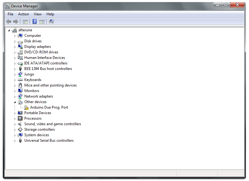

 warm token
What about one of these?
https://www.adafruit.com/product/387

Infrared LEDs are used for remote controls (they're the little LED in the part you point at your TV) and 'night-vision' cameras, and these little blue guys are high powered ones! ...
safe shell
scroll down for specs
warm token
Yeah, just noticed that, sorry...
safe shell
I've got some of those, nice b/c their invisible (850nm glow a little), though they do show up in some cameras.
safe shell
yeah, I haven't pushed that... i don't really have a way to measure brightness at that wavelength
pine bramble
@warm token
http://led.linear1.org/1led.wiz
warm token
Just to confirm, if I put more of the same LED in parallel, the forward voltage requirement stays the same, but the total current (as far as sizing one resistor for all) gets multiplied by the number of LEDs?
pine bramble
Ah I don't know how LED's work in parallel. It's a known idea; not sure if it's a recommended one.
If you have a decent series resistor in both legs it should be okay; you can lower them later to get the right currents to flow.
LED's aren't resistors so they kinda change dynamically.
One of those online calculators deals with series and parallel LED's.
warm token
That was my thought too, just individually resistor them. I'm not sure how they work in parallel either.
pine bramble
Well once there's an LED inline for each branch you cannot go too far wrong, as the LED's will current limit.
(LED brightness maps to the current flowing through the LED, and is only peripherally related to voltage).
 chilly vigil
Is there a TCP modbus library for m0 feather ?
surreal pawn
there might be
I found an arduino library for the wiz5100 rduino shield: http://domoticx.com/arduino-shield-ethernet-w5100-modbus-tcp-ip-slave/

Het is mogelijk om een Modbus TCP/IP Slave te maken met deze shield, hieronder een aantal voorbeelden met diverse bibliotheken.
safe shell
I had it working some time back... just used the Ethernet or Ethernet2 lib iirc
Guide says "Wiz5500. We recommend the Arduino Ethernet lirbary" ...that no longer works?
chilly vigil
@safe shell for this product? https://www.adafruit.com/product/3201

Wireless is wonderful, but sometimes you want the strong reliability of a wire. If your Feather board is going to be part of a permanent installation, this Ethernet FeatherWing will let you ...
chilly vigil
Ahh, ethernet2 library just saw it
safe shell
wow, longer ago than I thought... 2016 #include <Ethernet2.h> (On an ESP8266, b/c that's all I had at the time)
chilly vigil
Thanks @safe shell
safe shell
Mistakes can yield interesting insights. I forgot to clear the screen before successive displays of data, came back in a bit, and it's obvious which parts of the data are the most variable and which are the most static.
 surreal sorrel
Hello everybody, I'm currently working on a project with an Arduino Uno (most likely multiple Arduinos) and i want to be able to control it/them with Java programming. I'm learning how to use Java and Arduino and I thought maybe I could control each Arduino through a COM port on my PC, and be able to send simple commands through the serial connection. If anyone has done something like this before, or would like to try and help, I would greatly appreciate it! (DM me for specifics or if you would like to help)
north stream
You might look at a protocol called "Firmata", that can run on Arduino, communicate over a serial port, and let a variety of languages on host systems (including Java) talk to it. http://firmata.org/wiki/Main_Page
surreal sorrel
thanks madbodger, I found Bitlash, and i guess its kind of the same, ill check it out
north stream
Ah, didn't know about Bitlash. Looks like it's more useful for direct human interaction than Firmata, which appears to be designed more for binary data transfer.
surreal sorrel
yeah I could control the pins through the serial monitor
north stream
Yes, that would be quite handy for prototyping/debugging. When I built a computer controlled dimmer, I had a simple human-readable protocol as well as the usual binary Renard dimmer protocol.
 swift widget
@chilly vigil I’ve a project using ModbusTCP with the MetroM4 and the Seeed Ethernet W5500 shield. I ended up using Ethernet2 library because I didn’t have time to mess with Ethernet.h. But here’s something that might help https://forums.adafruit.com/viewtopic.php?f=63&t=161161
@chilly vigil Also, I had an issue with the Modbus library. I had to comment out the debug printf statements in the libmidbus modbus-tcp.cpp file. Let me know if you run into any issues..
Also, I’m interested in what you’re doing and how it works with feather. I chose metro because I already had a I/O expansion shield for my sensors. Though I first wanted the feather.
@chilly vigil One other thing: wasn’t sure if anyone pointed you to libraries. I never found a good Python library. The best one I saw was the Arduino library in the IDE. Very decent and easy to use. I set up a client and server in no time. Only thing is it’s kinda bloated and couldn’t be used in a bog-standard Uno (I didn’t have time or patience to trim it, among other things).
Btw, building another Modbus server this week on another MetroM4.
 winter flare
Hello all,
This is my first post here, and I am still very new to the embedded systems world -- I have a good deal of experience with high level programming on PCs, and some limited experience with x86 Assembly and Operating Systems, but I have virtually no previous experience with Microcontrollers.
Could I get help with troubleshooting a issue with uploading an Arduino sketch to an Adalogger Feather M0 over it's microUSB slot?
I am using a standard 2010-2015 era laptop running Ubuntu, and I was able to program and communicate with my Adalogger without issue until this morning.
By chance, I used a different USB slot on my computer today for my serial connection -- which seems to have been the trigger for the issue. That said, the USB slot is essentially the same -- I think one is a USB 2.0 and the other is a USB 3.0.
Either way, I have tried using every USB port on the laptop but no dice.
I can post the "verbose" error logs I got when attempting to upload.
From what I can tell -- the arduino programmer isn't detecting a bootloader on the board -- i.e. the board is detected, but it isn't issuing responses or something to that effect.
I am worried that I somehow fried the board without noticing.
Maybe I pushed the microUSB in too hard -- it's hard to tell how far deep the socket is -- resulting in damage to one of the soldiered connections?
Where would you start if you were checking whether (and where, for that matter) your board has been damaged in a way that prevents uploading a new sketch?
winter flare
Update : After reading some troubleshooting forum posts, I carefully examine the configuration settings for my arduino one more time in case I missed something.
As it turns out -- somehow my "(tool>board)" was set to Arduino M0 instead of Adafruit Feather M0. I don't remember changing that setting -- either way, after changing it back, my Feather is responding and appears fully functional.
Had a minor heart attack because it's a central part of my (undergraduate) class project and I didn't have the foresight to get 2 of them in case I somehow damaged it.
safe shell
I have a large file on SD I need to search quickly and frequently. It's ASCII with linefeeds, sorted but very unevenly distributed, so I don't think binary or similar search algos will help performance much. Thought is to index it upfront (nominally that probably means an array of 256 unsigned longs) and use the index to seek to closer positions. Is there a better way?
north stream
Depends a lot on the shape of your data and the kind of searches you need to do. For some situations, a hash table would work, for others, a dispersion sort, for still others, something like a binary or AVR tree. And yes, an index is a valid thing to examine as well.
 stoic anchor
Hey, I'm aware this is very vague/broad. But can anyone point me in the direction of being able to have one Arduino Mega communicate wirelessly with 8 Arduino Nanos, the nanos will send information to the mega (it would be nice if the mega could send a confirmation message back to the nano, but this is not necessary), the mega would do some calculations based on the data received from the various nanos. Thanks
 rough hamlet
use ESP32/ESP8266 which are very cheap
north stream
You could also use HC-05 type Bluetooth links, or simple RF links, or even infrared.
The main determiners of which approach is best for you will be cost, distance, complexity, bandwidth, reliability, and environment.
stoic anchor
I need to use Megas and Nanos. As for the wireless specifics, distance is minimal, maybe 1m x 1m open area is the maxmimum really
Just to make sure I'm following, if going with the HC-05 route, I would 9 modules in total (1 for the mega to receive on and 8 for the nanos to transmit on). This would allow the mega to listen to them all simultaneously?
safe shell
Thanks, @north stream I'll look into those as well.
north stream
I don't know how many simultaneous links the HC-05 supports. Might also want to look at BLE or a mesh network like Zigbee.
rough hamlet
I'm confused, it's written on INA219 description page that the chip can only have 4 different I²C addresses (https://www.adafruit.com/product/904), but on the I²C addresses compilation, it's written that INA219 can have 16 addresses (from 0x40 to 0x4F) (https://learn.adafruit.com/i2c-addresses/the-list). Is there a way to get extra addresses on INA219 ?
chilly vigil
@swift widget can you help me ? I don't understand how to read registers with modbusTCP , theres no example for it
stoic anchor
Hm, thanks anyway. Shall have to do more digging..
north stream
Yes, there is a way to get the extra addresses, but you'll have to use flywires to make the connections. The 4 addresses are gotten by simply bridging jumpers or not, but the additional addresses are gotten by tying the address leads to SCL or SDA instead of Vs+ or ground.
winter flare
while we are on the subject of bluetooth -- are there any common pitfalls in transferring files from microSD card -- through a Bluefruit chip -- to a host device (PC)?
I am wondering if I wrote a bad setup for my loop.
in particular, I think my code is assuming that the BLE can transfer data as quickly as I can read it off the microSD,
which will probably trip up when the memory reads outpace the transmission writes.
north stream
Reading shouldn't be a problem, the card won't send more until you ask for it.
neat oar
hey is it possible to connect two micro board on the same laptop
north stream
Probably? What kind of micro boards? Like Arduinos?
neat oar
yes arduino micro
i was going to use the mega arduino because it has a lot of analog pins, however the keyboard library is not compatible with mega
so i figured maybe two micro arduino boards could work if connected on the same laptop
how could that be achieved?
north stream
Just plug them in, they'll show up as two serial devices, you can choose which one you're working with in the Arduino IDE using the Tools -> Port menu.
north stream
I don't think the Arduino IDE will let you open two serial monitors at once, so if you wanted to receive data from two devices, you'd probably have to have a separate window or program that received the data from a second device and displayed it (or whatever you wanted to do with the data)
neat oar
how will i make the two programs run at the same time simultaneously
north stream
Normally when you upload a sketch to an Arduino, it starts running. If you then upload a sketch to a second Arduino, it'll start running as well.
safe shell
Is it possible to overlay two typedef struct? Sometimes I want to access a->b, but other times I just want a[i]. Can't seem to cast the struct as a simple type either.
north stream
Yes, that's called a "union".
union myunion {
  int      x;
  float    y;
  char     z[4];
  handle_t a;
};
Then if you declare a variable like union myunion foo; (or typedef it), all the members of foo will point to the same memory.
safe shell
cool, i'll give that a try, thanks!
safe shell
Ah, that works, but using one or the other seems to be mutually exclusive. I wasn't specific enough about my problem definition... I want to look at the same data two different ways simultaneously. Some structure with a blob of various types, but then I also want to be able to simply index into that fixed-size structure and pull out a byte a[i]. (as is, structure is filled with data, reading a[i] is all zeros)
(clearly C is not my forté)
north stream
Hmm, that should basically work, aside from issues with alignment and packing.
Like in my example if you stored a floating point number in foo.y, you should be able to read out the pieces of its representation in foo.z[0], foo.z[1], etc.
I just tried it. Wrote this program ```c
#include <stdio.h>
#include <math.h>
union myunion {
int x;
float y;
unsigned char z[4];
};
int
main()
{
union myunion foo;
foo.y = M_PI;
printf("%02x %02x %02x %02x\n", foo.z[0], foo.z[1], foo.z[2], foo.z[3]);
}
Running it yields ```
db 0f 49 40
If I set foo.y to 2, I get 00 00 00 40 instead
safe shell
OK, weird, explanations of union say writing to one union element can clobber previously written elements if it overlaps, but I see your point. Will look into why I'm not getting the bytes I want - read-only of a[i].
north stream
The other approach is type punning like ```c
struct mystruct data;
unsigned char * byteptr;
byteptr = (unsigned char *) &data;
Then you can access the bytes of data with byteptr[4] and the like.
safe shell
Thank you, I'll try that too
sly fox
@wet crystal It work. I try it with neopixle library and it work, it was my code on the setup and loop.
wet crystal
Cool
safe shell
Boom. type punning did what I expected. I still want to go back and get union working, that could be a useful technique to know. Thanks for all of your help @north stream
pine bramble
@neat oar In Linux, I think the easiest way is to use two different communications programs of equivalent function, pointing each to the correct communications port.
/dev/ttyACM0
/dev/ttyACM1
for SAMD microcontrollers, as an example.
They are assigned by the host PC operating system as you plug in their USB cables from the target board.
So if you needed a particular port with a particular target board, you sequence the order in which they are recognized by the host PC OS by plugging them in, in that same sequence.
Using two different comm programs obviates the need to try to change to the 'other' port from within a single named comm program.
north stream
You can also set up udev rules so particular devices will reliably show up with port names you select.
pine bramble
@north stream Would that work for say, two Trinket M0 boards?
north stream
I'm guessing it would, as long as they have different serial numbers.
I'm guessing they would. I just plugged in a Pyruler I had handy, which is essentially a Trinket M0, and it has the serial number CC24B91993932505B413E21360B1B0FF.
pine bramble
Sometimes you can use two copies of the same comm program, I think, but I generally use two different ones.
I have minicom and I think microcom for this use. There's several others.
north stream
I suppose it depends on what you're doing. If you're just using cat or screen, may as well use the same program. But if you're using Mu for one, you'd probably be better off using something else for the other. If you're trying to coördinate more than one device, it might make sense to write your own program to open/manage the serial ports.
pine bramble
I think I've at least tried PySerial (can't remember the exact name).
I really wanted to try 'expect' but didn't find time to figure that one out.
(used to use it to autologin to a BBS I think)
I also use 9term in plan9port for massive paste-ins over communications lines (telnet to a BBS, or a tty session with a microcontroller).
For reasons I don't understand, a large paste is 'released' properly to the far end of the connection, and no characters are dropped.
The equivalent behavior in minicom involves per-character and per-line timing delays built into minicom. The defaults aren't quite optimized for my use cases, so I adjust them as needed.
elder hare
i want to make variable in arduino that holds a long string, what type should i use?
surreal pawn
what do you intend to do to the string? can it be read-only?
elder hare
@surreal pawn
the text variable will change 🙂 it gets information "Artist - Song Title" from my python program (fetching Now Playing on Spotify)
and yea the text can be short or long 😛
there are some loooooooong titles out there
surreal pawn
well if you were on an uno I'd say char * but anything arm and just string is probably fine because of how much more ram the arm chips have
safe shell
String? https://www.arduino.cc/en/Reference/StringLibrary vs. https://www.arduino.cc/reference/en/language/variables/data-types/string/ String uses more memory, but it's very user-friendly.
 lusty bear

Adafruit Learning System
Get started now with our most powerful Bluefruit board yet!
Hi can anyone help in the setup according to this site?
im stuck at this step
how exactly do i add the path?
trying to install board for nrf52 onto my ARM Linux arduinoide
 amber bison
hiii guys
anyone help me with fingerprint sensor and using arduino mega
showing error in stk500v2_Recievemessage()
and some another with getsync()
maybe runtime error
or dunno wht
pine bramble
$ export PATH="/this/new/path:$PATH"
$ cat ~/.profile | tail -1
PATH="$HOME/my/path/bin:$PATH"
test with:
$ echo $PATH
(don't type the first dollar sign; it's the prompt provided by the shell and isn't something you typed)
 reef pollen
I accidentally turned off interrupts for too long. Now I can't program my Arduino pro micro (atmega32u4) over USB. Apparently usb comm uses interrupts.
Is there any hope for me? I have an UNO setup as a programmer and a high voltage programmer setup if it can help. I've heard ftdi is tricky on the 32u4 because it's internal serial? Thx

eBay
With 16Mhz crystal. Supported under Arduino IDE v1.0.5. The USB port is also available in single row pin strip to connect a USB cable (Host) to connect other Devices. Color : Blue.
pine bramble
Hey people! I have a question regarding the adafruit keypad-library. I have 5 rows and 3 columns. I can see that every button works fine when using the standard keypad-library. But when I use the adafruit keypad-library the 5th row stops working. Is there some kind of limit which I overlook? All other buttons work fine....
here is a picture of the code.
pine bramble
Found it. It was a hardware issue 😉
elder hare
so i bought some dot led matrix 8x8 and using the MD_parola library to drive them! and i noticed that the norwegian "Æ Ø Å" doesn't work. Now is that a MD_Parola library problem or because im using a string type variable
?
 unreal finch
olah
i have this code for calculating IK
which seems to work fine
but it gives me this....
north stream
@amber bison Are your board, port, and programmer set correctly? That error usually means it's trying to talk to a bootloader and it's not seeing the response it's expecting.
@reef pollen You shouldn't need FTDI for a 32U4, it implements comms directly with USB unless you've programmed it to do something else.
@elder hare It could be a font issue or an encoding issue.
@unreal finch It looks to me like the code is mixing degrees and radians. If servoAngle1 is in radians, it shouldn't have 180 added to it. If it's in degrees, it shouldn't be multiplied by 180. There are some other mathematical optimizations that could be made (atan2() is usually a more useful call than atan() when dealing with Cartesian coördinates, for example)
unreal finch
wait for atan2 is it for all the atans or just the first or second?
amber bison
@north stream I'll send u error msg wht it's showing... It was showing difficulty in communicating with programmer..
reef pollen
@north stream typically it's usb programmed, but as part of my program I used noInterrupts() and interrupts() and the length of time it's active is long enough to mess up the usb comm timing. So I'm looking for an alternative way to clear/reprogram it.
north stream
The program on the 32U4 or the program on the host?
north stream
That shouldn't matter: the 32U4 gets reset during the programming process which should halt the program and return to the bootloader.
sly fox
I am using a LilyPad Arduino USB - ATmega32U4 Board, but my LED lights red is not lighting up the whole LED, but some
the thing at light up on the LilyPad Arduino USB - ATmega32U4 Board is stat. What is SATA on the board
deft frost
im giving arduino a shot because circuitpython doesnt seem to be working.
I see that the function AnalogRead in arduino takes 100 micro seconds, that's 10,000 time per second. I need at least 30k so i'm planning to direct the ouput of mic into 3 analog pins on board and create a timer that's 30kHz and samples each pin once every 100ms
so some modular function on timer
is there a timer library that i can use to do this
north kelp
@deft frost I don't have experience with this library, but it claims to be faster:
https://github.com/avandalen/avdweb_AnalogReadFast

GitHub
Contribute to avandalen/avdweb_AnalogReadFast development by creating an account on GitHub.
There's also discussion of using DMA in this 2016 thread:
https://forum.arduino.cc/index.php?topic=443173.msg3050399#msg3050399
speeding up analogread() at the Arduino Zero
I'd recommend at least an Adafruit M0 or M4 board.
deft frost
rip they dont work for nrf52840
also i found https://github.com/JakeS0ft/nRF52Audio.git but this is only for audio playback right?

GitHub
Arduino audio library for nRF52. Contribute to JakeS0ft/nRF52Audio development by creating an account on GitHub.
north kelp
Looking at the headers, apparently just playback.
deft frost
unlukcy
north kelp
You could trade level-of-effort for money, and use a separate board to do your audio signal processing.
deft frost
unfortunately don't have space for another board i think
elder hare
why do i get garbage when i use
strcpy(SpotifyNowPlaying, pySpotify);
from the serial monitor
Arduino : @⸮⸮?~
@⸮⸮⸮?
Python : Beste fest stua i sandnes! =D
so the python is correct but the arduino is wrong
sly fox
The Neopixel Ring 24x can I used Adafruit Industries 3 x AAA Battery Holder with On/Off Switch and 2-Pin JST to light up the ring?
or do I need a battery holder that is 9v
My project is on 5v
 unkempt cradle
probably late and nobody will be able to help me in time, but does anyone know any troubleshooting steps with problems uploading ANYTHING to a feather m4 express?
plug in: no "new device" sound, reset button once causes the red LED to briefly flash, reset button twice causes it to be recognized in the file system, but it times out when trying to drag a uf2 onto it
yeah it keeps timing out every time i try uploading anything
 worthy thistle
@unkempt cradle what drive name shows up drive when you reset it?
@sly fox you need a microcontroller to send data to a NeoPixel, it will not light up with power and ground alone.
 terse canopy
is there any good explanation for why when I make a Serial.write() call on a SAMD board, I don't see the results show up on the other end?
I'm testing some code so I'm shuffling 2kb of data back and forth over the serial port
and sending the 2kb to the mcu works just fine, but after the Serial.write() call to send 2kb of results back, I don't see anything happen
am I supposed to explicitly call Serial.flush() or something?