#help-with-arduino
1 messages · Page 50 of 1
 little oyster
 surreal pawn
arduino ships with avr-gcc and should include avr-libc... though some parts are turned off by default like %f for sprintf
little oyster
ive looked in my files and apparently i don't
surreal pawn
what errors do you get?
little oyster
Specified folder/zip file does not contain a valid library
surreal pawn
I mean if you compile the code I pasted above do you get errors?
surreal pawn
Arduino.app/Contents/Java/hardware/tools/avr/include/math.h for me
 warm token
Is this https://www.adafruit.com/product/3505 an updated version of this https://www.adafruit.com/product/2488 ? Or are there more important differences besides just the new additions on the M0?

Metro is our series of microcontroller boards for use with the Arduino IDE. This new Metro M0 Express board looks a whole lot like our original Metro 328, but with a huge upgrade. ...

This is the Adafruit METRO Arduino-Compatible - with headers. It's a fully assembled and tested microcontroller and physical computing board with through-hole headers ...
warm token
@surreal pawn Do you know if the Trinket M0 can receive runtime commands via USB while it's running Circuit Python? Or is the serial-via-USB thing only available when it's running as native Arduino?
surreal pawn
circuitpython also does serial over usb
warm token
Are you able to point me in the right direction for how to accomplish this? I've found things for it to send commands over USB serial, but not to receive.
surreal pawn
in circuitpython?
warm token
Yeah
Like if I wanted to send a string from a PC over USB serial, how would that be received in CircuitPython? Would it be something like this link? I'm a software dev, but I'm missing some context with this particular framework.
https://stackoverflow.com/questions/48922189/receive-data-from-host-computer-using-circuit-python-on-circuit-playground-expre

Stack Overflow
I am using a Circuit Playground Express from Adafruit, and I'm programming it with Circuit Python.
I want to read data transmitted from the computer to which the Circuit Playground Express is conn...
surreal pawn
I haven't written code like that on circuitpython yet so I'd have to google and check the docs just like you
 tranquil plinth
Hello can anyone please help me with this?
I found a cool code for strip lights that do rainbow cycle. I want to know how to make this code to only cycle on blue shades. much appreciated!! 😄 Please DM me
#define NUMPIXELS 12

Adafruit_NeoPixel strip = Adafruit_NeoPixel(NUMPIXELS, PIN, NEO_GRB + NEO_KHZ800);

void setup() {
  strip.begin();
  strip.setBrightness(30);
  strip.show();
}

void loop() {
  // put your main code here, to run repeatedly:
  rainbow(120);
}

void rainbow(uint8_t wait) {
  uint16_t i, j;

  for (j = 0; j < 256; j++) {
    for (i = 0; i < strip.numPixels(); i++) {
      strip.setPixelColor(i, Wheel((i + j) & 255));
    }
    strip.show();
    delay(wait);
  }
}

uint32_t Wheel(byte WheelPos) {
  if (WheelPos < 85) {
    return strip.Color(WheelPos * 3, 255 - WheelPos * 3, 0);
  } else if (WheelPos < 170) {
    WheelPos -= 85;
    return strip.Color(255 - WheelPos * 3, 0, WheelPos * 3);
  } else {
    WheelPos -= 170;
    return strip.Color(0, WheelPos * 3, 255 - WheelPos * 3);
  }
}
@surreal pawn Ah ok, thanks for your help.
@tranquil plinth I haven't used this specific stuff before, but based on what I'm seeing in that example, each call to strip.Color takes three arguments, like strip.Color(red, green, blue) as numbers between 0 and 255. When WheelPos is less than 85, it alters red and green, ignoring blue, when below 170, it alters red and blue, ignoring green, and otherwise, alters green and blue, ignoring red. This lets it cover the full range of the color wheel.
Not sure exactly what you mean by only blue shades, so hopefully the above is enough to get you started in the right direction.
tranquil plinth
@warm token thank you
 potent ferry
Hello. Is there anyone that could suggest a same sort of dual digital pot but with
10 kohm instead of 100 kohm ?
Digital potentiometer is also called "Digital Pot" in short. It is a kind of mixed signal IC, which is able to dynamically change the internal resistors through MCU like Arduino.
 north stream
@potent ferry AdaFruit offers one: https://www.adafruit.com/product/4286

If you're a person like me that gets exhausted turning knobs all day, the DS3502 is just the ticket to calm all your knob-turning related troubles. Instead of having to turn ...
potent ferry
Thanks!
north stream
There are also DIP packaged options like MCP42010, DS1804, AD5220, etc.
potent ferry
What is the difference? What dip packaged means?
I meed 2 of them to control the x and y axe of a joysrick
north stream
DIP is a type of integrated circuit package designed for through-hole mounting in a printed circuit board. They're also handy for use with solderless breadboards.
Note: the MCP42010 includes 2 digital potentiometers in a single part.
potent ferry
My circuit is the circuit below, with the idea to replace the servomotors with digital potentiometers to control the axes of a joystick
north stream
Yes, that seems like it would be a more elegant solution than the servo-driven electromechanical one.
potent ferry
Which one would you go with ?
north stream
If you're using a breadboard anyway, the 2-circuit DIP option might appeal (it's SPI, which may or may not be important to you). As long as the potentiometers don't have more than the supply voltage across them, that might be the most cost effective approach.
potent ferry
For now i solder the circuit like this, but at some point the idea is to have this printed
When all is done i would have it printed ans maybe wireless if possible
north stream
There's more choice in surface mount chips if you're working with that, but the bigger DIP packaged ones are generally easier to work with for hand soldering.
potent ferry
Thanks!
 raven flame
what size Hex standoff do i need for arduino? (I'm naively hoping there's a one size fits all)
 woven mica
M3 I think
little oyster
does anybody know why i would have trouble uploading my code because COM3 isn't responding?
ive gone to device manager but it's not finding any ports
ive tried reinstalling drivers
different usb ports
 north kelp
@little oyster Which board are you uploading to?
Have you been able to upload to it before successfully?
little oyster
uno, and yes ive successfully uploaded the code yesterday
and ive been struggling for like almost an entire day (minus school hours) because the COM ports are being wack
surreal pawn
did you do something with pin 0 or 1?
wait, it should still show up as a com port if you were shorting out the just the serial on an arduino uno
little oyster
nope nothing with pin 0 or 1
 paper prawn
I have an M4 and I can successfully read files from the filesystem but I cannot write
    FatFile bootFile = fatfs.open(BOOT_FILE_NAME, O_WRONLY);
    bootFile.write("Test");
    bootFile.close();
 reef gull
Okay, I feel like I have a bit of copy-paste inconsistency. I'm trying to monitor two motion sensors and track the last time each of them saw motion. However, one works and the other does not.
Here's the relevant code.
#define UPPER_SENSOR   9
#define LOWER_SENSOR  12
volatile unsigned long upperMotion = 0;
volatile unsigned long lowerMotion = 0;

void setupSensors() {
  pinMode(5,  OUTPUT);
  pinMode(11, OUTPUT);
  pinMode(19, OUTPUT);
  pinMode(LED_BUILTIN,  OUTPUT);
  pinMode(UPPER_SENSOR, INPUT);
  pinMode(LOWER_SENSOR, INPUT);
  attachInterrupt(digitalPinToInterrupt(UPPER_SENSOR), onUpperRise,  RISING);
  attachInterrupt(digitalPinToInterrupt(LOWER_SENSOR), onLowerRise,  RISING);
}

void onUpperRise() {
  Serial.printf("Upper timer bumped to %d\n", upperMotion);
  upperMotion = millis() + TIMER;
}

void onLowerRise() {
  Serial.printf("Lower timer bumped to %d\n", lowerMotion);
  lowerMotion = millis() + TIMER;
}
I've verified that the sensor is outputting a voltage on the data line when I waggle things in front of it, and I've also verified the connection reaches pin 12
Monitoring the serial, I get the message for Upper (and indeed the handling for upper in the main loop) but I don't get any message at all for Lower
Using this image as a reference
https://cdn-learn.adafruit.com/assets/assets/000/046/245/original/adafruit_products_Feather_M0_Bluefruit_v2.2-1.png?1504885440

Ahh shoot. I stripped out the sensor code into a new sketch and it works the way it's supposed to. That means that there's something about the rest of my setup that's interfering.
north stream
At least you narrowed it down.
reef gull
I'm using two neopixel dma instances on pins 5 and 11. I can't use 23 (MOSI) because it's used by the BLE and 19 (A5) may need to go to another neopixel instance
Another thing I noticed is that my writes to pin 13, the onboard LED, haven't been working for a while in the other project, but it works fine in the sensor test sketch
Are there limits to how many pins can be used at a time?
I'm only using 4 now and 5 later, one more if you count the LED pin
paper prawn
OK this works :)
    File bootFile = fatfs.open(BOOT_FILE_NAME, FILE_WRITE);
    bootFile.print("Booting...");
    bootFile.close();
There aren't direct limits on how many pins can be used at a time, but some uses like DMA have weird side effects.
reef gull
Oh no
Reading docs again
https://learn.adafruit.com/dma-driven-neopixels

I'm not seeing anything about known problems with this specifically. I don't know what I'm looking for
I tried reversing the order the two interrupts were set up as well as removing all references to the builtin led. No dice.
north stream
Did you try switching the sensors, and which interrupt called which routine?
reef gull
I did not
Switching sensors results in the same thing. Whichever sensor is on pin 9 works as expected
What I haven't tried is disabling the interrupt on pin 9 to see if that allows 12 to work
Though I'm starting to thing I'm going to need to hunt around for a pin that just so happens to work or try to make this project work with one sensor
Or connect both sensors to the same input and not care which one is which
Okay I switched to pin 21 and manually connected it to that pin. That one reads
Oh. It works because 21 is EINT7, which is the same as pin 9
I have to find a different pin

20 works concurrently with 9. That's my answer
This is my second Arduino project. I don't think I like having to think about all these little gotchas
north kelp
@reef gull you’re doing great for your second Arduino project. I’d try doing it without interrupts, if possible, and maybe poll the sensors, instead. And if that didn’t work and I had to finish it quickly, I might add another microcontroller dedicated to the sensors. (Throw money at the problem.)
reef gull
I wonder if this same problem would prevent me from polling the pins manually? 🤔
Anyway, I just rerouted my PCB to point to pin 20. If all goes well, the prototype will now be functional enough to install
Though I'll keep that in mind. Might make the whole thing easier for me to think about if I were polling as opposed to interrupting
Turns out that EINT6 is used by the BLE as well and instead of getting my ISR to fire, I'm doing something that causes the BLE LED to flash
But I literally just tested it a little bit ago and it worked fine
north kelp
Also, looking at your interrupt routines, I’d make them simpler and faster. ISRs as a rule should be as fast as possible; mine usually just set a flag, which I check in my loop()
reef gull
I just noticed I routed my wires wrong. Let me fix that and try again
I accidentally went to DFU instead of SDA
north kelp
And that flag variable needs to be declared globally with the volatile keyword. See:
https://www.arduino.cc/reference/en/language/functions/external-interrupts/attachinterrupt/
The Arduino programming language Reference, organized into Functions, Variable and Constant, and Structure keywords.
All this interrupt complexity is something most Arduino coders don’t encounter until they’ve done quite a few projects.
reef gull
Yep, I got the volatile keyword on the longs. It started out as a boolean flag and I was relying on the PIR sensor's timer. However, it's timer was janky and I wanted something better. I suppose I could use the boolean to update the long in the loop
north kelp
Check out the doc above. millis() doesn’t work well in ISRs.
reef gull
Neither does Serial.print, according to another friend. I'll give the code another once over and clean up those ISRs
Boolean flag only, update timers in the loop() method, no printing in the ISR
north kelp
Sound good!
reef gull
Working as expected now. Thanks for the info!
 twin ginkgo
so i want to make a variable with numbers so like int num = 01, 02, 03, 04, 05
how can i write a script to check the num for a number and if the number is in the num then do _____
so like if num == 04 then do blank
twin ginkgo
number = 04
int num = 01, 02, 03, 04, 05;

if (number == num);{
 digitalWrite(1, HIGH);}
else
  digitalWright(1, LOW);
how can i get the script to look throw num for the number
surreal pawn
sure, if/else if/else is one way
The Arduino programming language Reference, organized into Functions, Variable and Constant, and Structure keywords.
or switch statements, which are annoying if you forget the break statement https://www.arduino.cc/en/Tutorial/switchCase
Open-source electronic prototyping platform enabling users to create interactive electronic objects.
 cedar mountain
The conventional way to do that would be to create num as an array of ints, and loop through it to see whether number is equal to any of the contents of the array. In this particular case, where the values are consecutive, it would be faster to use less-than and greater-than comparisons.
north stream
Side note: a leading zero can make some compilers interpret a number as base 8.
twin ginkgo
so it cant have 0 in it
north stream
Additional side note: the overkill way would be to create an array of function pointers and use the number to index into it. However, that approach is only appropriate for occasional situations, and can be deucedly difficult to debug if it goes off into the weeds.
cedar mountain
Another alternative, when the range of numbers is small, is to create a bitmask, i.e. have one bit for every possible value where you set it equal to 1 if the value is in the num list, 0 otherwise.
twin ginkgo
ok i found out i dont need the 0 i just need the 1 or 2 or 3
twin ginkgo
@north stream you where helping me out and i could not get the script you gave to to work but i got mine kinda to work but not quite ``` if (now.minute()== 16){;
mcp1.digitalWrite(2, HIGH);}
else{
mcp1.digitalWrite(2, LOW);}
if (now.minute()== 17){;
mcp1.digitalWrite(3, HIGH);}
else{
mcp1.digitalWrite(3, LOW);}
but i rethought what i wanted and i wanted the led to stay on at 1, 2, 3, 4 and the 4 led to turn off at 5
and i can do it with the hours too with no issues
but in order to do 1, 6, 11, 16, 21, 26, 31, 36, 41, 46, 51, 56 i would have to make the if statement that many times is there a way to do the variable like i had ```int one = 1, 6, 11, 16, 21, 26, 31, 36, 41, 46, 51, 56
if (now.minute()== one){;
mcp1.digitalWrite(2, HIGH);}
For that kind of regular pattern, you can use a modulus to check the ones digit, like "if ((now.minute() % 10 == 1) || (now.minute() % 10 == 6))".
twin ginkgo
i tried something almost like that but did not work
so the %10 == 1 that will do 1, 11, 21, 31, 41, 51?
cedar mountain
Yes. "% 10" says "divide by 10 and give me the remainder", so it'll produce the last digit of a number.
cedar mountain
Yep, it's a generic operation. "% 2" lets you check if something is even or odd, etc.
twin ginkgo
because i will do one script to turn 1 led on for 1, 6, 11, 16, 21, 26, 31, 36, 41, 46, 51, 56 one led for 2, 7, 12, 17, 22, 27, 32, 38, 42, 47, 52, 57 and 2 more scripts for 3 and 4
cedar mountain
If everything is an even multiple of 5 like that, then you may be able to simplify things by calculating "% 5" instead.
twin ginkgo
well 5,10 15, 20, 25, 30, 35, 40 ,45, 50 ,55 will be on diffrent leds
so sett up will be on leds
5 10 15 20 25 30 35 40 45 50 55
1 2 3 4 5 6 7 8 9 10 11 12
No, I meant, "% 5 == 1" would be true for 1, 6, 11, 16, 21, etc. Because both 1 and 6 have the remainder of 1 when divided by 5.
north stream
You can do two operations to get the selectors for each LED: ```c
int units = time % 5; // returns 0-4 to select LEDs 1,2,3,4
int fives = time / 5; // returns 0-11 to select LEDs 5,10,15, etc.
Then if you want to do a "count up" type display, you can see if units == 0 and turn off all the units LEDs, and otherwise turn on the matching one.
Like ```c
if (units == 0) {
// turn off all LEDs
for (led = 0; led < 4; ++led) {
digitalWrite(ledpins[led], LOW);
}
} else {
// turn on appropriate LED
digitalWrite(ledpins[units - 1], HIGH);
}
i cant use time due to its not declared
north stream
That was just an example, showing how the math works. I don't know what your actual variables are named, substitute "time" with whatever it is you're using.
twin ginkgo
oh
north stream
That's not ready-to-use code, it glosses over several details like declaring the "led" index variable, assuming there's an "ledpins" array containing the I/O pins for the units LEDs, etc. It's just to illustrate one possible approach.
twin ginkgo
ok i kinda got that i just have to figure out how to script it to how the script can use it
north stream
Yes, it's always "fun" to integrate two pieces of code, keeping the bits you want and modifying stuff enough to work smoothly together.
twin ginkgo
ok i got this and the 4 leds does turn on and off ```#include "RTClib.h"
#include <Adafruit_MCP23017.h>
#define NUM_ONES_LEDS 4
RTC_DS3231 rtc;
Adafruit_MCP23017 mcp1;
char daysOfTheWeek[7][12] = {"Sunday", "Monday", "Tuesday", "Wednesday", "Thursday", "Friday", "Saturday"};
void setup () {
//mcp
mcp1.begin();
mcp1.pinMode(2, OUTPUT);
mcp1.pinMode(3, OUTPUT);
mcp1.pinMode(4, OUTPUT);
mcp1.pinMode(5, OUTPUT);
//light
//rtc
#ifndef ESP8266
while (!Serial); // for Leonardo/Micro/Zero
#endif
Serial.begin(9600);
delay(500); // wait for console opening
if (! rtc.begin()) {
Serial.println("Couldn't find RTC");
while (1);
}
if (rtc.lostPower()) {
Serial.println("RTC lost power, lets set the time!");
//rtc.adjust(DateTime(F(DATE), F(TIME)));
}
}
void loop () {
//rtc
DateTime now = rtc.now();
Serial.print(now.year(), DEC);
Serial.print('/');
Serial.print(now.month(), DEC);
Serial.print('/');
Serial.print(now.day(), DEC);
Serial.print(" (");
Serial.print(daysOfTheWeek[now.dayOfTheWeek()]);
Serial.print(") ");
Serial.print(now.hour(), DEC);
Serial.print(':');
Serial.print(now.minute(), DEC);
Serial.print(':');
Serial.print(now.second(), DEC);
Serial.println();

Serial.print("Temperature: ");
Serial.print(rtc.getTemperature());
Serial.println(" C");

Serial.println();
delay(1000);

//lights
if (now.minute() % 10 == 1)
mcp1.digitalWrite(2, HIGH);
else
mcp1.digitalWrite(2, LOW);
if (now.minute() % 10 == 2)
mcp1.digitalWrite(3, HIGH);
else
mcp1.digitalWrite(3, LOW);
if (now.minute() % 10 == 3)
mcp1.digitalWrite(4, HIGH);
else
mcp1.digitalWrite(4, LOW);
if (now.minute() % 10 == 4)
mcp1.digitalWrite(5, HIGH);
else
mcp1.digitalWrite(5, LOW);
}
so that does work for the 1-4
just have to get them to stay on and turn off when 5 hits
it does turn off after 4 tho
so
north stream
It looks like your code turns them on one at a time, I'm guessing you want them to accumulate and all turn off when it gets to 5? ```
....
*...
**..
***.
....
  mcp1.digitalWrite(2, HIGH);
else
  mcp1.digitalWrite(2, LOW);

if (now.minute() % 10 == 2)
  mcp1.digitalWrite(3, HIGH);
else
  mcp1.digitalWrite(3, LOW);

if (now.minute() % 10 == 3)
  mcp1.digitalWrite(4, HIGH);
else
  mcp1.digitalWrite(4, LOW);

if (now.minute() % 10 == 4)
  mcp1.digitalWrite(5, HIGH);
else
  mcp1.digitalWrite(5, LOW);

if (now.minute() % 10 == 6)
  mcp1.digitalWrite(2, HIGH);
else
  mcp1.digitalWrite(2, LOW);

if (now.minute() % 10 == 7)
  mcp1.digitalWrite(3, HIGH);
else
  mcp1.digitalWrite(3, LOW);

if (now.minute() % 10 == 8)
  mcp1.digitalWrite(4, HIGH);
else
  mcp1.digitalWrite(4, LOW);

if (now.minute() % 10 == 9)
  mcp1.digitalWrite(5, HIGH);
else
  mcp1.digitalWrite(5, LOW);
``` for 1-4 and 6-9yess
north stream
The example code I put above should do that, and it's more compact (because it's making the computer do the work instead of the programmer)
twin ginkgo
so i would still keep the if but get rid of the else
north stream
You could do it that way, but you'd need to add something like "if (now.minute() % 10 == 5)" that turned all the LEDs off. Also, if you used % 5 instead of % 10, you could skip all the duplicated code for 6,7,8,9
twin ginkgo
yeah the dup does crash the code where leds dont want to turn on just flash for that led
ok that does work
twin ginkgo
ok the final script for the 1-4 and 6-9 thanks for the help if (now.minute() % 5 == 1) mcp1.digitalWrite(2, HIGH); if (now.minute() % 5 == 2) mcp1.digitalWrite(3, HIGH); if (now.minute() % 5 == 3) mcp1.digitalWrite(4, HIGH); if (now.minute() % 5 == 4) mcp1.digitalWrite(5, HIGH); //off if (now.minute() % 10 == 0) mcp1.digitalWrite(2, LOW); if (now.minute() % 10 == 0) mcp1.digitalWrite(3, LOW); if (now.minute() % 10 == 0) mcp1.digitalWrite(4, LOW); if (now.minute() % 10 == 0) mcp1.digitalWrite(5, LOW); if (now.minute() % 10 == 5) mcp1.digitalWrite(2, LOW); if (now.minute() % 10 == 5) mcp1.digitalWrite(3, LOW); if (now.minute() % 10 == 5) mcp1.digitalWrite(4, LOW); if (now.minute() % 10 == 5) mcp1.digitalWrite(5, LOW);
cedar mountain
For the off block, you can combine multiple statements with a single if condition using braces instead of repeating the same check, like:
if (a == b) {
do_it();
do_another();
do_it_again();
}
twin ginkgo
i tried that ill try it again wont hurt but the led just blinks
yeah it wont turn the led on it will just blink
north stream
Basically, what he's suggesting is replacing your "off" logic with c //off if (now.minute() % 5 == 0) { mcp1.digitalWrite(2, LOW); mcp1.digitalWrite(3, LOW); mcp1.digitalWrite(4, LOW); mcp1.digitalWrite(5, LOW); }
twin ginkgo
ok i think thats wat is it the brakets
to return 5's its / 5 == 5
correct?
or / 10== 5
north stream
Return 5s? For the next range of LEDs or what?
twin ginkgo
yes
north stream
That was the second line I posted: ```c
int fives = time / 5; // returns 0-11 to select LEDs 5,10,15, etc.
ok thats what i have but its not wanting to light up
// leds 1-4
if (now.minute() % 5 == 1)
  mcp1.digitalWrite(0, HIGH);
if (now.minute() % 5 == 2)
  mcp1.digitalWrite(1, HIGH);
if (now.minute() % 5 == 3)
  mcp1.digitalWrite(2, HIGH);
if (now.minute() % 5 == 4)
  mcp1.digitalWrite(3, HIGH);
//leds 5-55
if (now.minute() / 5 == 5)
  mcp1.digitalWrite(4, HIGH);
if (now.minute() / 5 == 10)
  mcp1.digitalWrite(5, HIGH);
if (now.minute() / 5 == 15)
  mcp1.digitalWrite(6, HIGH);
if (now.minute() / 5 == 20)
  mcp1.digitalWrite(7, HIGH);
if (now.minute() / 5 == 25)
  mcp1.digitalWrite(8, HIGH);
if (now.minute() / 5 == 30)
  mcp1.digitalWrite(9, HIGH);
if (now.minute() / 5 == 35)
  mcp1.digitalWrite(10, HIGH);
if (now.minute() / 5 == 40)
  mcp1.digitalWrite(11, HIGH);
if (now.minute() / 10 == 45)
  mcp1.digitalWrite(12, HIGH);
if (now.minute() / 5 == 50)
  mcp1.digitalWrite(13, HIGH);
if (now.minute() / 5 == 55)
  mcp1.digitalWrite(14, HIGH);

//off
// leds 1-4
if (now.minute() % 5 == 0){
  mcp1.digitalWrite(0, LOW);
  mcp1.digitalWrite(1, LOW);
  mcp1.digitalWrite(2, LOW);
  mcp1.digitalWrite(3, LOW);
}
// leds 5-55
if (now.minute() / 5 == 5){
  mcp1.digitalWrite(4, LOW);
  mcp1.digitalWrite(5, LOW);
  mcp1.digitalWrite(6, LOW);
  mcp1.digitalWrite(7, LOW);
  mcp1.digitalWrite(8, LOW);
  mcp1.digitalWrite(9, LOW);
  mcp1.digitalWrite(10, LOW);
  mcp1.digitalWrite(11, LOW);
  mcp1.digitalWrite(12, LOW);
  mcp1.digitalWrite(13, LOW);
  mcp1.digitalWrite(14, LOW);
}```now.minute() / 5 will return 0, 1, 2, 3 like in the comment
So you'll have something like ```c
if ((now.minute() / 5) == 1) {
mcp1.digitalWrite(4, HIGH);
}
if ((now.minute() / 5) == 2) {
mcp1.digitalWrite(5, HIGH);
}
if ((now.minute() / 5) == 0) {
// turn 'em all off
mcp1.digitalWrite(4, LOW);
mcp1.digitalWrite(5, LOW);
mcp1.digitalWrite(6, LOW);
mcp1.digitalWrite(7, LOW);
mcp1.digitalWrite(8, LOW);
mcp1.digitalWrite(9, LOW);
mcp1.digitalWrite(10, LOW);
mcp1.digitalWrite(11, LOW);
mcp1.digitalWrite(12, LOW);
mcp1.digitalWrite(13, LOW);
mcp1.digitalWrite(14, LOW);
}
Or you could skip the division and just check for now.minute() == 5 – the modulo operation is more useful if you're going to do math on the results like ```c
if ((now.minute() / 5) == 0) {
// turn 'em all off
} else {
mcp1.digitalWrite((now.minute() / 5) + 3, HIGH);
}
That last digitalWrite statement will calculate the LED pin from the result of the division, so it handles all the LEDs with one line.
However, you can still do it with individual if statements if you prefer.
twin ginkgo
wow i dotn know what i was thinking lol
twin ginkgo
ok im trying to run 2 mcp23017 but when i connect the seconed one it stops communicating info to arduino
command screen
north stream
Did you set the second MCP23017 to a different address?
north stream
Hmm, looks right, maybe address 0x20 and 0x21, and the DS3231 should be on 0x68. The DS3231 board should have the I2C pullups on it.
twin ginkgo
?
north stream
Just trying to figure out the wiring, address map, etc. to see if I can see anything for you to try.
My guess is that the left hand MCP chip has the address pins all grounded, so it should respond to I2C address 0x20.
twin ginkgo
yes its all ground
north stream
The right hand MCP chip seems to have A0 to +V and the others grounded, which should have it respond to address 0x21. Presumably you have the software set up to connect the MCP instances to those addresses.
You could always run an I2C address scanner sketch to see if all three chips answer for the expected addresses.
twin ginkgo
how can i do the scanner?
north stream
First, are you calling something like mcp2.begin(1) to specify the address of the second MCP chip?
twin ginkgo
Adafruit_MCP23017 mcp1;
Adafruit_MCP23017 mcp2;


char daysOfTheWeek[7][12] = {"Sunday", "Monday", "Tuesday", "Wednesday", "Thursday", "Friday", "Saturday"};

void setup () {
//mcp
mcp1.begin();
mcp1.pinMode(0, OUTPUT);//1
mcp1.pinMode(1, OUTPUT);//2
mcp1.pinMode(2, OUTPUT);//3
mcp1.pinMode(3, OUTPUT);//4
mcp1.pinMode(4, OUTPUT);//5
mcp1.pinMode(5, OUTPUT);//10
mcp1.pinMode(6, OUTPUT);//15
mcp1.pinMode(7, OUTPUT);//20
mcp1.pinMode(8, OUTPUT);//25
mcp1.pinMode(9, OUTPUT);//30
mcp1.pinMode(10, OUTPUT);//35
mcp1.pinMode(11, OUTPUT);//40
mcp1.pinMode(12, OUTPUT);//45
mcp1.pinMode(13, OUTPUT);//50
mcp1.pinMode(14, OUTPUT);//55
mcp2.begin(1);
mcp2.pinMode(0, OUTPUT);//1
mcp2.pinMode(1, OUTPUT);//2
mcp2.pinMode(2, OUTPUT);//3
mcp2.pinMode(3, OUTPUT);//4
mcp2.pinMode(4, OUTPUT);//5
mcp2.pinMode(5, OUTPUT);//6
mcp2.pinMode(6, OUTPUT);//7
mcp2.pinMode(7, OUTPUT);//8
mcp2.pinMode(8, OUTPUT);//9
mcp2.pinMode(9, OUTPUT);//10
mcp2.pinMode(10, OUTPUT);//11
mcp2.pinMode(11, OUTPUT);//12
Yup, that looks right.
You can grab an I2C scanner sketch here https://playground.arduino.cc/Main/I2cScanner/
I tend to run this any time I hook up an I2C device, just to make sure it shows up the way I expect.
twin ginkgo
how long does the scan take?
ok so if i unplug that chip scan shows the 0x20 and 0x68 im guessing theh 68 is my rtc and 20 iis the chips
the one chip
i found out what happend
ground was in power
got it now
twin ginkgo
where would i set the bit on the rtc to change 24 to 12 hours
north stream
It's bit 6 in register 2
twin ginkgo
how do i change the register
north stream
Depends on which library you're using.
north stream
There are like eight different DS3231 RTC libraries.
north stream
If you're using Tom Odulate's library, you could use ```c
rtc.SwitchRegisterBit(DS3231_TIME_HOURS, DS3231_BIT_12_24, true);
where would that go
north stream
You could either have a separate program to set that (the DS3231 will remember it for you) or you could just tuck it into your setup() routine to slam the bit every time you run your sketch.
twin ginkgo
im useing RTClib by adafruit
so i open a new arduino program put the code in and upload?
north stream
I think with RTClib, it's slightly more involved: ```c
uint8_t bits;
bits = rtc.read(0x02);
bits |= 1 << 6;
rtc.write(0x02, bits);
Yeah, just have the rtc header and instantiation, and then put that stuff in setup() and upload it. Then it should stay in 12 hour mode until it loses power or you change it.
If you already have a program you use to set the clock, you could add the code in there.
north stream
You could also put it in your main script.
twin ginkgo
when i verify it says bits is not a name type
north stream
Hmm, probably conflicts with something else. Change "bits" to some other variable name.
 swift widget
I want to use an analog pin both to read an analog value and then to drive a digital write. Basically, I want to read a voltage across LED and then blink LED from the same analog pin. The LED is acting as a poor light detector. This was inspired by: https://spritesmods.com/?art=minimalism
From what I can find, you’re just supposed to declare the nature of the pin before each read or write. But in the simple code below, the analog read (which comes first) works only the first time. I’ve tried permutations (such as explicitly declaring pin INPUT), but once the pin is set to digital OUTPUT, the analogread returns zero.
I’ve tested this on an Arduino Uno, and related code on an atTiny45. LED and resistor as usual on designated analog pin. LED blinks fine. LED analogread works fine on its own.
Any ideas what I’m doing wrong? Please @ me any replies so I don’t miss them.
Code below:
void setup() {
  Serial.begin(9600);
}

void loop() {
  //read analog signal
  //pinMode(LED_PIN, INPUT);
  int sensorValue = analogRead(LED_PIN);
  // print out the value read
  Serial.println(sensorValue);

  //now do blink LED
  pinMode(LED_PIN, OUTPUT);
  digitalWrite(LED_PIN, HIGH);   // turn the LED on (HIGH is the voltage level)
  delay(1000);                       // wait for a second
  digitalWrite(LED_PIN, LOW);    // turn the LED off by making the voltage LOW
  delay(1000);                       // wait for a second
}```@swift widget sparkfun had a post doing the same using digital read in a loop to measure the time it takes the voltage across the led to drop below a threshold
It's a known trick that we can use LEDs in reverse. We'll explore how to use them as photodetectors with Arduino and create a simple demo that responds to hand swipes.
swift widget
@surreal pawn Oh, man. Thank you. I’ll give it a try, as it keeps the pin digital the whole time.
swift widget
@surreal pawn I just realized, when re-reading the article, that the detecting LED can't be used as an illuminating LED. In my case, I want it to be a detector and an illuminator. Someone suggested I do two analogReads in a row. I had tried it, but I'll try again and pay attention to how. Let's see.
This linkhttps://edu.workbencheducation.com/cwists/preview/11068x

LEDs work in two ways: giving off light and detecting light! In this activity, we learn how to turn an LED into a simple light detector.
Pretty cool, tho.
 frank current
Ok so I have this little newbie project that I'm learnin about transistors. This arduino code has digitalWrite(2, HIGH) to activate a thing but nothing is working. I have the 5v and gnd wired to a breadboard and d2 wires to the base of the transistor, 5v to the collector and emitter to the motor (power and the out to ground)
I recieved 8 transistors in this kit but they all identical. I'm supposed to have 6 pnp and 2 npn. But I cant tell em apart
anyway the multimeter reads 0 and i'm just not sure what's wrong
 viscid snow
Anyone know of allready existing code or projects where someone uses an arduino to give off a signal (led blink for example)when a windows notification is received?
north stream
@frank current You should probably have a current limiting resistor for the base. If your multimeter has a diode test function, you can use that to identify your transistors and their pinout.
frank current
I'm so new, does this one have one?
Also: thanks. :)
trying to find everything that came with this. I'm sure it lists everyhing it does somwhere
yup it does. now to figure how that works and then figure out which resistor i wanna use.
(googling it ofc)
north stream
Yes, it does, the position with Ω and a diode symbol and a sound symbol
Switch it to that, then press (probably) the "select" button until a diode symbol shows up on the display.
frank current
ok so Input to Emitter and Com tp base fluxuates from .9v to 1.3v or so.. just all jumpin around. That means it's PNP, yeah?
north stream
A transistor (out of circuit) should behave as like two diode junctions. You should get current flow and about 0.6V drop from the base to emitter and base to collector.
frank current
oh this MM has a hfc and adapter for testing the transistors!
north stream
With the base positive, you should get flow for an NPN transistor, and with the base negative, you should get flow for a PNP transitor
Oh, even better!
frank current
yeah in the PNP slot is reads 190. cool. so now i know what i have 🙂
so if i'm right i'll power the emitter, and base (resistors likely needed to the base i think?) that'll open the collector to switch on the whatever
north stream
The usual lashup is with an NPN transistor in what's known as a "common emitter" configuration. The emitter is grounded, and the control signal goes (via a current limiting resistor) to the base. The current flowing into the base turns the transistor "on", allowing current to flow from the collector to the emitter. The motor would then be connected to the positive power supply and collector.
Note that if the motor power supply is different than the logic power supply, they both need their return (or "V-" or "ground" or "zero volt") leads connected together and to the transistor's emitter.
frank current
okay. Nice. I'll test and sort all these transistors to find my NPN and try that next. I have a 220 1k and 10k resistors on hand.
thanks again 🙂
north stream
1k is a good starting value for a base resistor.
frank current
Testing by trying to light a LED. Arduino code is just setup setting d2 to output and writing HIGH to d2 in loop. D2 to a 1k resistor to the base, emitter to ground and collector to a 220 resistor to an led then from led to ground. Breadboard is powered by a separate module providing 3v.
even just running power from the power module into the 1k res to the base doesn't trigger it so it's not the code gonna check all the connections
frank current
whenever i have something running from a positive power supply (the other side of the breadboard) into the collector it turns on! BUT that stays on regardless of if i power the transistor or not
i need to do more reading i suspect
 turbid bloom
Hi guys, I just bought an arduino CH340 online and found out that what I needed was the board replica for uno r3 instead
Any idea how i can still run a program meant for r3 on the CH340?
I'm really new to this stuff so much help appreciated🙏
north stream
Yeah, should go from positive supply to LED, then LED to collector.
The CH340 is just the USB to serial chip, otherwise it programs just like any other Uno. You probably just need a CH340 serial driver.
turbid bloom
Alr installed the driver
Basically tryna replicate what he does in this video with an uno r3 but stuck at the DFU mode section

If you have watched the previous video, this video is a full tutorial to explain how to use Arduino board to day skip automatically, so you don't have to do it by hand for hours!
Pokemon Sword & Shield Playlist ► https://bit.ly/35bzv0I
Subscribe to me ► http://bit.ly/2g33iPg
__...
north stream
I don't think Arduinos have a DFU mode, that's odd. Does it show up as a serial port on your computer?
If a serial port shows up, look for it in the Ports menu of the Arduino IDE. If it shows up there, you should be able to upload a sketch to it after selecting that port.
frank current
well it works for the LED but the motor is a no go 🙂
PROGRESS! 🙂
time for a break 🙂
raven flame
@frank current here's what you should be looking at for a motor. NPN closing a relay, that drives a motor. Transistors can blow up easily under high current so you want to stress them as little as possible. And with a 100x transistor, you don't want anything less than 10k resistor to hit saturation of 50ma@5v - it's not about limiting the base current so much as the collector/emitter current.
http://tinyurl.com/uj2ofh3
frank current
So why a relay and then excuse me while i google what a relay is and what it does 🙂
also it's a 5v motor for a water pump. it's just a simple (for anyone else) automated watering system for my fern 🙂
raven flame
A relay lets you use lots of current; So it all depends on the requirement of your water pump.
If your 5v motor requires less than 600mA constant supply then you can use a 2N2222 transistor which can power 800mA of current continuously (75% for reliability)
but if your motor needs 2A, then you need a relay or a motor driver.
and if you don't want to power a relay (because they need power to keep the switch closed) but still need high current; you can use a power mosfet, some of which can handle up to 100W; but you have to heatsink them because they get warm 😉
raven flame

Anti kickback diode
In this video we take a look at the inductive kickback from a DC motor and how it can damage your circuits. The use a diode to block the kickback and observe on the oscilloscope how the spurious voltage is lowered.
5 boards for about $22 in about 7 days http...
raven flame
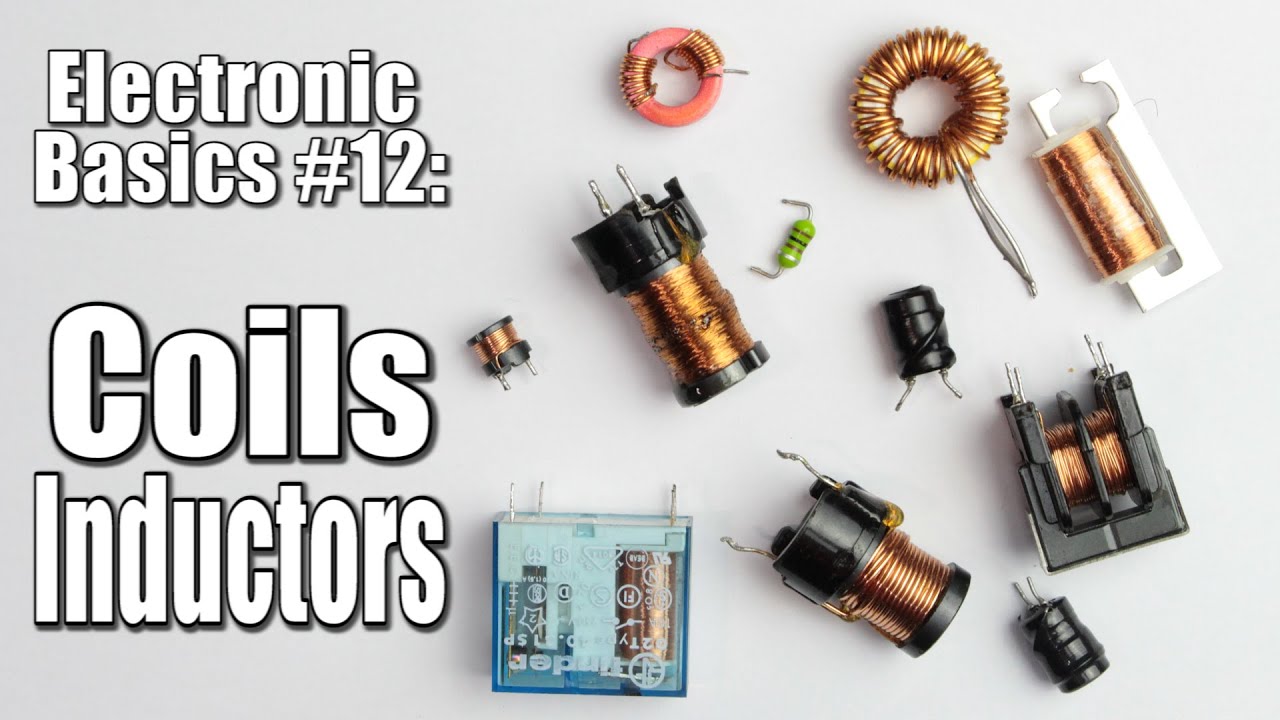
Previous video: https://youtu.be/pxNLTRl36HQ
Facebook: https://www.facebook.com/greatscottlab
Twitter: https://twitter.com/GreatScottLab
Support me for more videos: https://www.patreon.com/GreatScott?ty=h
In this video I will explain why coils/inductors are so important in diff...
(both are> don't blow up your transistors with a dc motor)
 honest fractal
I just dont understand why my HC-05 Modules wont respond??
I dont understand whats wrong 😦
#include <SoftwareSerial.h>

SoftwareSerial mySerial(4, 3); // RX, TX

void setup()
{
  // Open serial communications and wait for port to open:
  Serial.begin(9600);

  // set the data rate for the SoftwareSerial port
  mySerial.begin(115200);
}

void loop() // run over and over
{
  if (mySerial.available())
    Serial.write(mySerial.read());
  if (Serial.available())
    mySerial.write(Serial.read());
}```@raven flame Thanks 🙂
twin ginkgo
so i got my script working and i think im ready to move it off the arduino i do have a atmega328p chip
with bootloader already on
but i dont have the data sheet to know how to hook it up
north stream
You don't need much, just reset circuit, crystal or resonator, power, and serial connections.
Open-source electronic prototyping platform enabling users to create interactive electronic objects.
twin ginkgo
i was looking at that but ok cool
twin ginkgo
what is a resonator or crystal
north stream
The AVR chip can either use an internal RC oscillator (no external parts, but you have to run a modified configuration) or an external frequency determining component, either a crystal (higher cost and accuracy) or a resonator.
That determines the CPU clock speed. An ordinary Arduino uses a 16MHz crystal for a 16MHz CPU clock. The 3V Arduinos usually run at 8MHz.
twin ginkgo
so all your basicly doing is making a simple arduino board on a breadboard without all the pins and stuff correct?
north stream
I was guessing that's what you wanted.
 mighty vigil
I'm using timer1 from Paul S. to periodically execute a function. I'm also changing the period too. If I change the period, does it take into account the time that's passed? Like, if it's 1000 before, and I change it to 600 after 500 microseconds , would it wait 600 or 100 microseconds?
surreal pawn
@mighty vigil I hate to be that guy, but read the datasheet
surreal pawn
no, for the chip. the library is just a thin wrapper to set the timer control registers
ben heck's most recent video might be a better place to start. let me find a link

In this video we generate a Z80 clock using the Atmel's high speed timer and do some tricks to access the Atmel as a peripheral device.
he uses a timer on a 32u4 (arduino leonardo, but the uno and mega are very similar) to output the clock pulses for the z80
it's programmed in arduino but he spends a lot of time messing with the timer registers and referring to the datasheet
also you probably should check the source for the library to see how it's interacting with the control registers and see if it's resetting the counter itself
so what you want to know is if setting OCR1A, OCR1C, and TCCR1 timer registers reset the counter
oh, and even knowing the answer to that, the answer is to your question is "it depends" because if they don't reset the counter, the timer1 code can still change the clock divider for the timer: https://github.com/PaulStoffregen/TimerOne/blob/ce0fa0b7965f189925d8b7dbba49d562f7c0a4b3/TimerOne.h#L55
GitHub
TimerOne Library with optimization and expanded hardware support - PaulStoffregen/TimerOne
 pulsar bramble
Hey.
I got the need for a few PT100 sensors. THey will be used in quite a harsh enviroment. So I want to connect them over Wifi instead of having alot of cables running.
What products from Adafruit would you use to connect 1-2 PT100 and send that over Wifi to a raspberry Pi?
The amplifier boards + some sort of ESP or Circuitpython mini board?
Could probably add a small battery in there also to make sure that nothing nasty gets into the enclosure I plan to build for it?
cedar mountain
Possibly the Feather Huzzah ESP8266? It even includes a battery charger.
I don't know your other design constraints, but you might also consider switching to PT1000, since the lower drive current makes it easier to use them with regular GPIOs.
 proven mauve
I am having a heck of a time voltage dividing... I have a pro mirco arduino currently set to deliver 5v. The circuit I'm trying to isolate has 6 separate 74hc595 shift registers hooked to 16 RGB LEDs. It looks like it's all of that is consuming around 26mA when I white out all the LEDs at once. So I'm trying to make a voltage divider to make it run at 3v because I like the brightness better and I don't want the entire device to run at 3v. So I was playing with resistors while the max circuit pull was 8mA.. and even at that current I'm having issues. When I finally got resistor values to consistently be above 3v (100R for R1, 28K2 for R2, larger values for R1 would cause it to drop under 3v under load) when the circuit is on, it still has... issues.
like, it'll have visual anomalies, the LEDs which should be completely off will have a tiny little bit of light shining, and other issues.
It's a resistor-based voltage divider just... not going to work when I'm trying to draw 26mA? Or do I need to change my values to accommodate the current?...
surreal pawn
yes, a resistor based voltage divider isn't the right answer when you're driving a variable number of LEDs
why not one resistor per LED?
proven mauve
So I should stick with a small linear regulator?
surreal pawn
you'll probably want different current settings for the different colors (red LEDs have a lower voltage or current requirement than green than blue)
proven mauve
each LED has a resistor, Right now they're all 220ohm and it all looks good. At 48 resistors for the project I didn't really want to change that part up, when dropping the voltage puts it in a really nice place
surreal pawn
sure, having different voltage regulators would get the effect you want, but it's cheaper and fewer parts to just have different series resistors
or switching to a more expensive LED driver chip that does current limiting
proven mauve
I have a lot of linear regulators here, but not enough resistors to change over to anything in that quantity, and shipping lead times are pretty lame 😦
I appreciate it, sphere. For the next one of these I'll have to just get the right resistor values lol
or pwm the leds...
surreal pawn
you'll still want the resistors to limit current
raven flame
have you tried limiting the current with a NPN transistor below the stack of LEDs? if you use 5v with 100k resistor on the base it will limit the total current running from ground.
you could get a 1Mohm potentiometer to find a good value for the base resistor to get the brightness you want.
like this?
http://tinyurl.com/rbm5rjv
most people run transistors at saturation; letting through 100x the base current ; but you can choke it.
proven mauve
@raven flame That's crazy, I'm amazed every day at the simple concepts I haven't learned yet and how practical they are
Thank you for taking the time to draw that. It looks like the 200k, 100k, and 10k are all options to pick from and you would only use one of them in practice, yeah? (as in only the one you picked to run current through)
raven flame
yes in the chart it's just a 3 way switch; for a real circuit you'd just have one 😄
i'm surprised i understand it tbh 😄
i only started studying electronics a month or so ago; started with old valve circuits which i understood right away, all this solid state nonsense is confusing! 😄
LEDs have a "fixed" voltage drop, so most of the voltage drop happens across the resistor. which in turn reduces the current. i=v/r - less current, less light.
proven mauve
So Many ways to skin cats 😄
raven flame
thankfully, ohms law is immutable 🙂
proven mauve
ha
 ruby rampart
21:31:57.778 -> Temp: 25.19C - Pressure: 1014.19hPa - Altitude: -7.82m - Humidity: 35% -- well, that all looks right other than the altitude 😄 (I ponder if altitude derived from pressure is going to be foolish for a storm/inside)
also the feather is smaller than I thought 🙂
 wraith current
@ruby rampart barometric altitude only works if you know the pressure at Sea level
ruby rampart
then how is this lib offering that as a function? I bet it's hardcoding a value
float A = pressure / 101325; yep 😄
ruby rampart
I also doubt the pressure will change enough to determine that I'm on the 3rd floor vs ground floor
BME280 might be good, but not that good? :\
wraith current
If the sensor is sensitive enough it could tell.
ruby rampart
but it has to have that reference
wraith current
If it's mobile you could modify the code to report relative altitude
ruby rampart
for my usage it's moot anyway; they're all going to be in the same plane of altitude, but the example code gave alt and that made me think 🙂
I really wanted the BME280 for temp/pressure/humidity, as that's roughly my learning goal: to make a temp/pressure/humidity sensor for Mozilla's IoT thing, using a ESP8266. Should be straight forward, but lots of planning as I also want to make the sensors battery powered and in a 3D printed enclosure, so lots of learning 🙂
 rocky igloo
Normal daily variations in barometric pressure are large compared to the change in pressure with altitude. That is the extent of my wisdom on the subject. 😄
north stream
I know fitness trackers can distinguish between walking and climbing (even a single floor) by variations of atmospheric pressure, but I don't know what sort of sensors they use.
rocky igloo
Mine uses baro pressure, and it's often confused by sudden weather changes!
wraith current
@ruby rampart feather 8266 has built in lipo battery charging.
ruby rampart
That's half the reason I bought it rather than some random 8266 arduino 🙂
sweet, using my own function where I can provide a 'reference' pressure, I get an altitude that's more reasonable (still not 100% right, but at least not negative 😄 )
cedar mountain
The relative accuracy of modern barometric pressure sensors is pretty amazing... sub-meter height changes are totally reasonable to detect. As you noted, though, on longer time scales that gets confused with weather variation.
ruby rampart
yep, my desk is apparently 3m higher than when I started the code earlier 😉
 fair reef
Hi, everybody. I've been struggling for about a month now to figure out how to configure the Adafruit SPIFlash library for the Serpente R2 Arduino-compatible board. I've even tried soliciting Fiverr help up to $30 with no luck. I just want to know, without taking up too much time: it is possible to configure this:
https://github.com/adafruit/Adafruit_SPIFlash/blob/master/examples/SdFat_ReadWrite/SdFat_ReadWrite.ino
For the Serpente R2:
https://serpente.solder.party/r2/docs/downloads/
Right?
north stream
Do WriteBlock() and ReadBlock() work?
In other words, have you tried the flash_manipulator sketch?
fair reef
I haven't tried any direct manipulation because I don't want to ruin the formatting of the chip as it is. I suppose I could try reading, see if it works
north stream
Ah, it's already formatted?
fair reef
Yeah, it comes as a CircuitPython plug'n'play
north stream
You should still be able to read blocks with flash_manipulator
north stream
What variant.h error?
fair reef

GitHub
Contribute to adafruit/Adafruit_SPIFlash development by creating an account on GitHub.
I'm trying to copy across some definitions somebody on Discord gave me a while back, but now I'm just getting weird syntax issues
I really hate this whole thing, I've never struggled with a coding problem so much in my life
north stream
Hmm, the driver supports both SPI and QSPI flash, and the board has it, but the board definition doesn't seem to have the matching #define.
fair reef
Would it warrant contacting the board developer? He hangs around this server.
Because I can't get it right
https://gist.github.com/phunanon/01da2c5b2bb43ffcf8a1c00243e9275e
This was my attempt a while back
north stream
Might be. Arturo?
fair reef
Yes
north stream
I don't have the JSON for that board, so I can't download the board package to examine the variant.h file
fair reef
I'm using this
Actually, that's not his repo, is it
it's the uLisp person's
So I could raise an issue on there?
north stream
Maybe. I tried looking at the AdaFruit boards' variant.h, but I can't find definitions there either
fair reef
Adafruit has a definition for the Serpente at all?
north stream
No, I was looking at the definitions of boards that had an SPI flash chip.
fair reef
Ah, right
 thorny kayak
Hey guys, I'm looking to build a battery powered LED strip w/arduino and mic to pulse the LED's to music. Specifically looking to get this together for a music festival, with the LED lights strung along the outside of my backpack. I was hoping to use the battery pack I already have, but I understand that USB packs may not be best suited for something like this. I am looking for something that is easy to pack/small enough to carry around all day at a fest. I'm not looking to power the LED's for that long - I get that they can use quite a bit of power.
Pack I already have - https://www.anker.com/products/variant/powercore-speed-20000-[upgraded]/A1278011
And would love to use some waterproof LED's like these: https://www.amazon.com/ALITOVE-Individual-Addressable-Waterproof-Raspberry/dp/B01DLYSH6U/
Which Arduino should I get? Will a USB powerpack be enough to power an arduino/LED strip? Are there different LED strips that would be better suited for something like this? I'm not familiar with all these specs/requirements so am hoping someone here can help! I am a software engineer so any kind of programming or fiddling with software isn't much of a concern.
 prime crater
OK, so step one is reading this for general guidelines: https://learn.adafruit.com/adafruit-neopixel-uberguide/powering-neopixels

Adafruit Learning System
Everything you always wanted to know about Adafruit NeoPixels but were afraid to ask
And then after that, take a look at how many lights you plan to have and how bright you need them. Generally speaking, if this is at night, you can run them at a surprisingly low brightness and be effective.
For example, I have a project that has 150 neopixels that very happily runs off a modern USB based battery pack
thorny kayak
This is what I was originally looking at, but would like to get an arduino in there somehow
https://www.reddit.com/r/electricdaisycarnival/comments/bg3qef/upgraded_my_hydration_bag_from_last_years_design/

reddit
553 votes and 66 comments so far on Reddit
prime crater
OK, so cool, you already have the LEDs, and you have 144. In essence, you are only replacing the controller with your own design.
As it's a wearable, you might want to look at the FLora line https://www.adafruit.com/product/659

FLORA is Adafruit's fully-featured wearable electronics platform. It's a round, sewable, Arduino-compatible microcontroller designed to empower amazing wearables projects.FLORA comes ...
It'll be a good form factor, and you can sew it on to your bag
Oh, hmm, it doesn't have 5v output. I'm not sure how well it will do for 144 pixels.
thorny kayak
yeah thats one of the things im kinda stuck on
im excited to get started with this project, just confused on what kind of parts im going to need for it
prime crater
Your sticking points are going to be getting your audio hooked up and getting a signal that will work for your lights.
I like the ItsyBitsy line because they have a pin that (if you power the board via USB) will have the logic at that same level.
The ItsyBitsy m4 is nice that way
thorny kayak
this is enough for 144?
512 KB flash, 192 KB RAM
prime crater
Yes. The math there is 3 * numberOfLights for how much RAM you need.
Except in certain circumstances when you're powering the lights through DMA or something, but those libraries will help you out with the math there.
192KB is very roomy for a microcontroller.
😄
So I have a sound activated project myself, however I had to make my own enclosure for it to contain the mic module + board.
I use this one https://www.adafruit.com/product/1063

Add an ear to your project with this well-designed electret microphone amplifier. This fully assembled and tested board comes with a 20-20KHz electret microphone soldered on. For the ...
thorny kayak
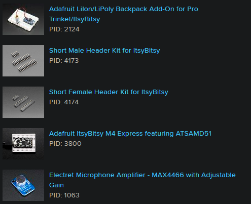
@prime crater I need some kind of cabling for this right? this is my cart
https://i.imgur.com/f0cA498.png
 raven flame
are those neopixels individually addressable?
 acoustic nebula
yes
raven flame
right arduino 😄 i just took it from it's wrapper what do i do with it haha
step 1> get that led sketch working
step 2> i2c screen 😄
ruby rampart
I'm about to do the same with the huzza; step 1: blink sketch, step 2: Mozilla IoT compatible device giving BME280 readings
raven flame
okay blink sketch working with a 2n2222 powering another led on a different power supply with common ground ✅
ruby rampart
yay, exceptions :\
raven flame
if i use analogue input, do i need to put any current limiting on it? or is that automatic?
cedar mountain
Generally ADC inputs are fairly high-impedance, in the vicinity of 50k.
raven flame
so 5v max is going to be virtually no current 😄
cedar mountain
Yep. It's small but finite, so if you're trying to measure something that can't supply any current at all, you'd need a buffer, but sounds like it's the opposite case here.
raven flame
i have a 10k pot from 5v to ground; and reading the wiper
cedar mountain
I wouldn't expect any trouble there offhand, but you might double-check the ADC datasheet to be sure, as it's in the same ballpark.
raven flame
it's all working 😄 sending a pwm brightness to LED based on 0->1023 value of the potentiometer 🙂
now for the real test> how accurate is it vs my multimeter lol
it's about 10% out - but that's because the max voltage is 4.8 😄 let me change my math
now it's spot on
 drifting dock
is abs meant to always return an integer regardless of the input? or is it board specific?
raven flame
abs removes the sign from the number you give it returning always a positive value
eg: abs(1) = 1; abs(-1) = 1; abs(-2) = 2;
drifting dock
yeah but abs -0.5 = 0
I haven't tested on a proper arduino, I'm using the new megatiny core for the new attiny series
raven flame
that's because ardunio's implementation is int without decimals
drifting dock
not sure if it's a flaw in the core, or if arduino is just poorly document
since the arduino documentation says "number", not integer
north stream
You can use fabs() if you want floating point absolute value
drifting dock
thanks, didn't know that existed
north stream
May need to include <math.h> to use it
raven flame
how much voltage can i plug into my arduino jack plug?
ruby rampart
aha, so if you forget to initalise the webthingadapter you've defined, you get exceptions 😄
raven flame
never mind that i found a 9v battery and a jack for it - works a charm.
ruby rampart
was going to say, the v-in for the jack plug is wide
raven flame
right so> how do i tell how much voltage is on the V++ ? if i don't know the exact value to 1% my math is wrong 😦
ruby rampart
7 to 12v, IIRC
raven flame
ok plugging in to 5v ADRF fixes the inaccuracy 🙂
i might have to use a 4.7 zener diode to fix the high rail 🙂
the only problem is they get non-linear at the top end lol
raven flame
btw, if you need a scope DS213 is amazing 😄
 wet rock
Hi everyone, hope this is the right place to ask for some help. I'm working on a project which requires me to use a TFT-ST7789 display. I'm using a Adafruit feather NRF52840 Express board. All I want is to display the graphic test on the small display, each attempt I have is unsuccessful. At this stage my assumption is that the SPI pins aren't properly configured.
what do you guys think?
#include <SdFat.h>
#include <bluefruit.h>
#include <Adafruit_GFX.h>    // Core graphics library
#include <Adafruit_ST7789.h> // Hardware-specific library for ST7789
#include <SPI.h>
these are the libraries I've included
north kelp
@wet rock You can use triple backticks around code to make it easier to read here:
#include <SdFat.h>
#include <bluefruit.h>
#include <Adafruit_GFX.h> // Core graphics library
#include <Adafruit_ST7789.h> // Hardware-specific library for ST7789
#include <SPI.h>
thanks! I didn't know that
north kelp
@wet rock Which ST7789 display? Can you show a picture of your wiring?
```cpp [some code] ```
wet rock
VIN = USB
SCK = SCK, MOSI = MO, TFTCS = 13, RST = 12, DC = 11
https://www.adafruit.com/product/4383 i'm using this display 🙂

Say hello to our 1.14" 240x135 Color TFT Display w/ MicroSD Card Breakout – we think it's T-F-Terrific! It's the size of your thumbnail, with glorious 240x135 high res ...
north kelp
Since Feathers all use 3.3V logic, I'd try using the 3V pin to power your display instead of USB, which is 5V.
wet rock
thanks, just changed that
I installed all the libraries as suggested by the website, and then ran the graphicstest sample code
#else
// For the breakout board, you can use any 2 or 3 pins.
// These pins will also work for the 1.8" TFT shield.
#define TFT_CS        13
#define TFT_RST        12 // Or set to -1 and connect to Arduino RESET pin
#define TFT_DC         11
#endif
and changed the port numbers
north kelp
@wet rock Did you follow the guide on editing the Adafruit_ST7735 libraries?

Adafruit Learning System
Adafruit 1.14" 240x135 Color TFT Display + MicroSD Card Breakout - ST7789
wet rock
I made those changes suggested in that page. But i didnt edit any libraries
north kelp
Oh yeah… sorry… changes look like they're in the graphicstest source code.
@wet rock What's line 65 read in your graphicstest code?
And line 102?
wet rock
do you mean this?
north kelp
That's line 102. Looks good.
wet rock
line 65 '''cpp
Adafruit_ST7789 tft = Adafruit_ST7789(TFT_CS, TFT_DC, TFT_RST);
that is line 65
I uncommented that one and commented the otherone
north kelp
@wet rock Did you alter the sample graphicstest code to add includes for SdFat and bluefruit, as you posted above? If so, I'd try deleting those and using the unaltered graphicstest.
wet rock
I just did that. The builtin neopixel is now WHITE
it was off before. Nothing on the display yet
north kelp
I guess that's a little progress.
What's the Serial Monitor show when you run it?
Do you have a multimeter handy? I'd check every connection for continuity. I'd also check my wiring for every wire to make sure I didn't say, swap MOSI and SCK or something.
@wet rock If you're still having no luck after that, I'd try posting your question on https://forums.adafruit.com/viewforum.php?f=47
Be sure to include a clear description, your source code, and a sharp image of your wiring (as you already did here, thanks!). The Forums are a good place for issues that can't be resolved easily here on the Adafruit Discord.
wet rock
will try doing that. Thanks for all you help and time 🙂
prime crater
@thorny kayak Sorry for the delay getting back to you, but I don't think you'll need the lipoly backpack since you plan to power it via the USB battery pack. Additionally, depending on how permanent and secure you need it, you can probably put everything on a small solderless breadboard.
thorny kayak
no worries
@prime crater would this work to power the LED's from the battery? https://www.amazon.com/HOMREE-Converter-Voltage-Regulator-Standard/dp/B01MEF293V/ref=sr_1_2?keywords=USB+to+5V+converter&qid=1581561458&sr=8-2
nvrm wrong i/o
prime crater
No need to do all that
Since you are powering the board via USB, that means the USB pin on the board will carry 5v
And pin 5 you can use as your signal pin
Since it is fancy and runs at 5v logic on the itsybitsy boards.
So you can hook the +v (red wire) to the USB pin of your board, DIN (green wire) to pin 5, and GND (black wire) to ground.
thorny kayak
whoah the itsybitsy board can power that whole strip?
Voltage: DC 5V
Power: 0.3W ± 0.01% per LED
for 144 led
prime crater
Right, it's not the board powering it
It's the battery pack. That pin is basically passthrough
thorny kayak
ah cool
prime crater
The board itself runs on 3.3v and has a regulator for that.
thorny kayak
okay so... power will run usb to the board, board has a passthrough for power to the led strip
prime crater
Yep
thorny kayak
will i need resistors? not even sure what they do
prime crater
I think I linked you the neopixel uberguide yesterday, but read through that. You'll probably want a resistor between board and the data in of your strip
thorny kayak
found it
prime crater
And, it's recommended to put a reasonable capacitor between the V+ and GND to filter the power for your pixels...but I'm bad and never do that.
Cause I can't ever fit it in to my wiring easily. 😄
thorny kayak
Adding a 300 to 500 Ohm resistor between your microcontroller's data pin and the data input
Adafruit Industries, Unique & fun DIY electronics and kits : - Tools Gift Certificates Arduino Cables Sensors LEDs Books Breakout Boards Power EL Wire/Tape/Panel Components & Parts LCDs & Displays Wearables Prototyping Raspberry Pi Wireless Young Engineers 3D printing NeoPixe...
prime crater
Yeah, that's the resistor I'm talking about
thorny kayak
470 out of stock rip
prime crater
470 ohm is what I use (and fits the recommendation)
But yeah, that guide should help you out. Take a look at some of the project guides on Adafruit, there's examples for how to do audio reactive projects
north kelp
@thorny kayak @prime crater For a 144-pixel strip, I'd not connect the power to the ItsyBitsy's USB pin, but rather to the 5V+ of the pack itself, if you're turning on more than a few of the pixels on the strip.
thorny kayak
hmm how should i connect the USB powerbank to the strip?
north kelp
(Worst case for current draw of the strip is 8.64A.)
The traces on the Itsy are probably good for 500mA or so.
I refer you to the wonderful NeoPixel Überguide:
Adafruit Learning System
Everything you always wanted to know about Adafruit NeoPixels but were afraid to ask
thorny kayak
https://www.reddit.com/r/electricdaisycarnival/comments/bg3qef/upgraded_my_hydration_bag_from_last_years_design/
is what im trying to replicate, with an arduino to create some other custom effects. just have no idea how im going to connect my powerbank to the LED strip + arduino
strip im using is in that link
north kelp
I'd suggest reading the guide above; especially the sections on best practices and powering NeoPixels.
prime crater
Ahh, OK. I was just going by what I've done before. 😄
north kelp
If you only turn on say 5 or so pixels at a time, you can wire your strip's Vin pin directly to your ItsyBitsy's 3.3V pin.
north kelp
I did that for this project:
https://twitter.com/erico/status/1092261259544674304


Proud to win #devcamp’s “coolest hack”! @neil_c_heather & I demo #geekyjacket our @flutterio-controlled, blingy wearable.
Flutter controls an @adafruit Feather M0 MCU via Bluetooth LE. NeoPixel LEDs gently diffused w black chiffon (@JoAnn_Stores!)
Thx @dom & @iPhoneDevCamp....
 Twitter
thorny kayak
Twitter
thorny kayak
so it looks like i may have to cut up a usb cable to connect the powerbank to the strip?
north kelp
You can, or you can use a USB breakout.

Simple but effective - this breakout board has a USB Micro-B connector, with all 5 pins broken out. Great for pairing with a microcontroller with USB support, or adding USB 5V power to a ...
You also may need a level shifter, if you decide to power your strip from 5V, since the ItsyBitsy M4 uses 3.3V logic.
prime crater
The ItsyBitsy line has a level shifted pin
north kelp

Adafruit Learning System
Level shifters are like little bilingual translators for your electronics!
prime crater
Which is why I like using it for neopixel projects
north kelp
I believe all digital pins on the ItsyBitsy M4 are 3.3V, not level shifted.
prime crater
Pin 5 is level shifted
north kelp
Oh look at that! I learned something!!
thorny kayak
i can see myself getting really carried away with this lol
north kelp
You're right, @prime crater !
prime crater
Also, where can I read more on the amperage limits for the traces?
thorny kayak
going to be fun once all parts are here and can put it together
prime crater
@north kelp I ❤️ the ItsyBitsy line. I know them almost back to front. 😄
north kelp
@thorny kayak Often, but not always, pin limits are in the primary guide for your microcontroller (in the Adafruit Learning System.)
prime crater
But I've never considered the limits for the traces between the USB V+ and the pin itself.
north kelp
When in doubt, don't wire high current devices Vin directly to an MCU's pins.
prime crater
Well, it's to the board.... 😉
But yeah
So, for my 144 LED project I have very complicated power distribution, but that's because I want to run it at FULL BRIGHT so it's visible in the daylight
If you're powering from a battery bank, set your lights to brightness 64 or thereabouts. It's plenty bright at night or indoors.
north kelp
Pinouts for the ItsyBitsy M4:
https://learn.adafruit.com/introducing-adafruit-itsybitsy-m4/pinouts
 prime crater
And it shouldn't draw too much power from your bank.
north kelp
Note also that your standard 5V USB battery pack may only give you 1A output.
prime crater
Modern, name brand, ones usually will give 2A
At least on one port
I think he linked his, let me take a look
north kelp
Even if it has 2+A output, I'd expect to need the resistors on the USB line to tell the pack to bump up to 2+A.
prime crater
Yeah, his does 2A
north kelp
Those are dictated by the USB standard; phones use these to tell the pack to go to 2A.
This guide is also handy for reducing power consumption:
https://learn.adafruit.com/sipping-power-with-neopixels
 prime crater
I was looking for that guide yesterday
Also, as a note, he's actually powered this project off a battery pack successfully already.
He's just wanting to use his own programming instead of an off the shelf controller.
north kelp
That's awesome.
prime crater
I'm assuming "he" but I shouldn't.
north kelp
I just want to make sure someone doesn't place an overheating voltage regulator in a plastic backpack. 😉
prime crater
It's ok, the 5v voltage regulation will be in the battery bank, right next to the volatile lithium. What could go wrong? 😉
I trust the battery pack to be fused and protected.
north stream
You could do like cell phone manufacturers and use the lithium cell as a heatsink.
prime crater
It's an Anker one
Unlike the time I decided it was safe to not put a fuse on the 12v lead acid battery in a backpack.
@thorny kayak Take a look at that guide @north kelp posted.
thorny kayak
the original link wasnt done be me, thats not my project
north kelp
It's one thing to try it out and have it seem to work for a bit. It's another to actually do the math on all the parts, pixel counts, animations, and be a bit more sure it will run for a few hours.
prime crater
Ahhhh
thorny kayak
but it does demonstrate that its possible to power the strip with a usb powerbank
north kelp
It totally is possible. Just don't run the NeoPixel bog standard test code on a 144-pixel strip, without sufficient power.
prime crater
Well, I run 150 Neopixels off a 2A battery bank at a brightness level of 64 without issue.
But, YMMV and I may be doing something wrong
north kelp
In the project I posted above, I'm powering a 144-pixel strip from a single 18650 3.7V lithium battery.
But I'm careful in my code.
prime crater
My 144 pixel one has crazy power distribution, but that's because full brightness.
And yeah, you have to be careful with your code.
If you opt to use FastLED instead of Adafruit's library, it actually has the option to limit the brightness based on estimated power consumption.
(that's what I use)
north kelp
@prime crater So you're drawing 2.25A max.
prime crater
Well, sorta. Pure white is a boring pattern. 😄 Aside from that, FastLED automatically reduces brightness if I try to draw more than 1.5A.
If you're doing rainbows and/or fully saturated colors, you'll usually be much lower in power draw.
I have white as an option, but I basically just use it when I need a flashlight. 😄
prime crater
Me too...
But I don't have a gif

The Seed and Feed Marching Abominable marching band performing Big Noise from Winnetka at the 2018 Inman Park Festival
You can sorta see it there. Daytime gig, which is why I have insane power distribution
prime crater
Yep
north kelp
Subscribed.
prime crater
Hahah
Thx
And sorry to anyone trying to ask questions, we got pretty far off topic. 😄
Also, @north kelp , I like the "simple" look of the stripes on the arms of your jacket. I keep going huge and complex, and never getting things finished because of it.
north kelp
Aww, thanks. I just had time for one stripe, since it was a 2-day hackathon.
Construction notes are here:
https://github.com/oesterle/geekyjacket/tree/master/materials_and_construction

GitHub
Adding Flutter to clothing. Contribute to oesterle/geekyjacket development by creating an account on GitHub.
wet rock
@north kelp it started suddenly started working. I don't know why and how
thanks heaps for your time mate 🙂
north kelp
Awesome, @wet rock! Could just be a sketchy connection. Breadboarding is like that sometimes.
 fiery bobcat
looking at https://forums.adafruit.com/viewtopic.php?f=57&t=123491&p=653817&hilit=interrupt+nRF52#p653817
The nRF52 runs a simple operating system that swaps between your code and the code that makes the radio work. It has to suspend your code periodically to do that, which can cause hiccups in the millis() and micros() counters.
Is there a way to disable the mechanism that is swapping between my code and the code that drives the radio (even at the cost of disabling the radio)? I'm trying to time pulses with interrupts on a nRF52 Bluefruit LE and I'm realizing the timing is off
 burnt island
I doubt it. I suspect that the arduino code is run when the real base OS decides to let it. If the timers work like the Atmel ones you might be able to read one yourself. You'd have to deal with translating ticks to real time and dealing with wrap around yourself, but it's a possibility.
fiery bobcat
Yeah, if there was a way I could read how long rtos left my code and came back, I might be able to math it out. I don't know how to do that though
burnt island
some deep diving into the datasheet to see how the timer modules work might be in order. I think the SAMD21/51's are capable of triggering a timer to start & stop from interrupt pins, so the timing sensitive part would be handled by the chip and the code would only have to come along at some point after to read the results. I don't know if the nRF timer modules have that capability, or if it's exposed through the RTOS. Anything along that path would be purely raw embedded programming with no help from the Arduino framework though
hell, the RTOS might provide a pulse timing function, but that would be in a different 400 page datasheet.
fiery bobcat
thanks. i'll dig some more, hopefully something turns up
cedar mountain
In addition to the timers, Cortex M4's often have a CPU cycle counter as part of the ARM spec, called CYCCNT or similar. So that might be useful for figuring out elapsed time when other interrupts are suspended.
raven flame
int analog_value = analogRead(A0);
input_voltage = (analog_value * 5.0) / 1024.0;
I'm still having problems with the digital voltage reader - I need accuracy of 1%.
The code is assuming that the Vcc line is 5.00V exactly so if Vcc is actually 5.1V I need to change the code.
Is there any way to detect the exact voltage on the external voltage line, or will i just have to create a hyper accurate power supply?
raven flame
looks like LM336 will be my best friend 😄
 pulsar charm
does anyone know how to view ArduinoJson?
north stream
What, the source? https://github.com/bblanchon/ArduinoJson
pulsar charm
Oh as in the parsed JSON objects
I find it incredibly difficult to navigate data I didn't serialize.
north stream
Hrm. I'd probably parse the JSON with Python and then use that to somehow visualize the results.
 fervent egret
#define DT A0
#define SCK A1
#define sw 2
char Incoming_value = 4;
long sample=0;
float val=0;
long count=0;
unsigned long readCount(void)
{
unsigned long Count;
unsigned char i;
pinMode(DT, OUTPUT);
digitalWrite(DT,HIGH);
digitalWrite(SCK,LOW);
Count=0;
pinMode(DT, INPUT);
while(digitalRead(DT));
for (i=0;i<24;i++)
{
digitalWrite(SCK,HIGH);
Count=Count<<1;
digitalWrite(SCK,LOW);
if(digitalRead(DT))
Count++;
}
digitalWrite(SCK,HIGH);
Count=Count^0x800000;
digitalWrite(SCK,LOW);
return(Count);
}
void setup()
{
Serial.begin(9600);
pinMode(8, OUTPUT);
pinMode(SCK, OUTPUT);
pinMode(sw, INPUT_PULLUP);
calibrate();
}
void loop()
{
count= readCount();
int w=(((count-sample)/val)-2*((count-sample)/val));
Serial.print("weight:");
Serial.print((int)w);
Serial.println("g");
if(digitalRead(sw)==0)
{
val=0;
sample=0;
w=0;
count=0;
calibrate();
}
if (Serial.available() > 0 )
{
Incoming_value = Serial.read();
Serial.print(Incoming_value);
Serial.print("\n");
if (Incoming_value == '1')
digitalWrite(8, HIGH);
else if (Incoming_value == '4')
digitalWrite(8, LOW);
}
}
void calibrate()
{
for(int i=0;i<100;i++)
{
count=readCount();
sample+=count;
Serial.println(count);
}
sample/=100;
Serial.print("Avg:");
Serial.println(sample);
count=0;
while(count<1000)
{
count=readCount();
count=sample-count;
Serial.println(count);
}
delay(2000);
for(int i=0;i<100;i++)
{
count=readCount();
val+=sample-count;
Serial.println(sample-count);
}
val=val/100.0;
val=val/100.0;
}
What's wrong with this code?
 honest nimbus
  {
    digitalWrite(SCK,HIGH);
    Count=Count<<1;
    digitalWrite(SCK,LOW);
    if(digitalRead(DT))
    Count++;
  }```
`Count = Count << 1` followed by `Count++`? After 24 cycles through, that's gonna be huge. 1 << 23 is over 8 million. And then you raise that to the power of 0x800000. Which is equal to 1 << 23...but raising 8 million to the 8 millionth power is
a big number
I'm putting that into Wolfram|Alpha and it's just going "nope" at me
Oh! Apologies, that's bitwise XOR
You're going to have to tell us what hardware is attached and what you want it to be doing, I think. What this is for is not obvious from the uncommented code.
 marsh forge
Think we bricked or fried our feather LoRa. We plug it in and only get a quick blink of the yellow light. Double pressing the reset button does nothing. Anyone have thoughts on how to test further?
And we are using a know good usb cable 😉
raven flame
any tips for i2c projects? 🙂
@fervent egret have a look at shiftin - it does synchronised clock cycling for reading serial data.
https://www.arduino.cc/reference/en/language/functions/advanced-io/shiftin/
The Arduino programming language Reference, organized into Functions, Variable and Constant, and Structure keywords.
cedar mountain
Watch out for 7-bit versus 8-bit address confusion. And remember that pullup signals are somewhat "weaker" than actively-driven buses, so they can be more susceptible to problems with long cables and EMI.
raven flame
i thought i2c was active low 😐 goes back to reading
cedar mountain
It is, but the highs come just from pullup resistors, so the low->high transitions can be asymmetrically slower.
raven flame
i suspect that my scope is going to get a good shakedown 😄
cedar mountain
90% chance that I2C will "just work" if you're not doing anything crazy, so don't be too worried.
raven flame
10% chance i blow up the IC board trying to solder the headers on to the board 😉
 robust gazelle
anyone know how to get the RF specs for the Arduino Pro Mini 5v/16mhz board?
surreal pawn
in what way? the PCB impedance or something else?
ruby rampart
GPIO #16 can be used to wake up out of deep-sleep mode, you'll need to connect it to the RESET pin if I'm reading that right, I need to connect 16 to RST to use ESP.deepSleep, right?
robust gazelle
@surreal pawn more like noise and isolation
surreal pawn
there's no radio transmitter, it uses a linear voltage regulator, and you can download the PCB design and schematic
there's no electrical isolation
cedar mountain
@ruby rampart Yep, it looks like the timer interrupt pulls GPIO16 low, so you have to loop that back to the RESET pin in order to wake up from deep sleep using that event.
ruby rampart
Sweet. Now to learn some basic PCB design... 🙂
proven mauve
I'm trying to control 6 74hc595's brightnesses by having their OE pins connected to the A0 pin on my pro micro... However when I analogWrite out to that pin, any value under 128 is full brightness and any value 128 or above is completely off. I have mixed success cycling the value between 0 and 255, but that kindof defeats the purpose of using the analog pin for this....
it's almost like the OE can't handle the speed of the analog write or something
Also, this happens when I put the analogWrite directly into the end of setup()
 humble anchor
I used EasyEDA for PCB design! It is sponsored by JLCPCB but is really simple and works great and you can import components from other people, but make sure to double check them @ruby rampart.
@proven mauve It is not an analog input?
proven mauve
And when I cycle the value manually there is a noticeable flicker to the leds...
Bonnom, its an inverted digital input, but from what I've read using analogWrite is a good way to put it to use. If the value is 0 allows the LEDs to shine, and if there's voltage it turns them off. Lots of tutorials use analog write to cycle the voltage on and off quickly to simulate brightness without being able to see the flicker
it's supposed to work the same as using PWM to control a single led's brightness
 proven mauve
omg I'm an idiot
humble anchor
Use a PWM pin, for the pwm pins see this picture
humble anchor
Haha, everyone makes has a small oversight from time-to-time
proven mauve
GOt my wires crossed between analog input and PWM
ha, I love this place 😄
thank you Bonnom
humble anchor
No problem! BTW if you ever need precise PWM control/debugging. I would recommend a teensy. They have adjustable frequencies and resolution, with a page what the maximum frequencies are at a given resolution!
Probably not needed for what you do now. But it can be nice to have in case you ever get problems with pwm
proven mauve
Yeah, I have a few, they work awseom for MIDI routers lol, but this is just a little beat box so it doesn't need that much uumph
humble anchor
Did you know about that PWM page? https://www.pjrc.com/teensy/td_pulse.html
I really find this very usefull
proven mauve
ha no, the way that site is organized I'm always finding new crevasses, lol. Thanks again 🙂
also, moving to pin 9 immediately fixed the issue
flicker-free
break is over tho, back to work
Happy V-Day!
humble anchor
Ok great, you too!
 patent vessel
whats a good way to get several true analog DAC outputs? say i need 16 channels
i was thinking of a multiplexer but.. maybe there is a better solution? ive never worked with a multiplexer before.. maybe SPI is better then i2c for the pure sake of coding it?
 river tangle
hello guys i've got a little problem. I've download the IDE in my Rasberry Pi 3. But i can't the menu bar... what i go is something like that
two functions and de {} that it...
north stream
@patent vessel The usual way is to use DAC chips. If you're breadboarding, there are DIP packaged ones like TLC5628 and LTC1660 that are SPI controlled and give 8 outputs apiece, you could use two of them for 16 outputs.
 tepid comet
I'm using an esp8266
north stream
Those happen to be 8-bit DACs. As you go to more bits and more channels, the selection of through-hole, breadboardable parts dwindles quickly, but there are plenty of surface mount options.
tepid comet
but it doesn't connect the mqtt
Connecting to MQTT... Connection failed
Retrying MQTT connection in 10 seconds...
patent vessel
ahw yeah i saw
i looked at the data sheet
surface mount is completely cool with me!
patent vessel
i have a reflow station and could make a pcb and make a breadboard thingy for it just to test
north stream
For 16 channels and 12 bits, there are 13 choices on DigiKey https://www.digikey.com/products/en/integrated-circuits-ics/data-acquisition-digital-to-analog-converters-dac/701?FV=-8|701%2C153|80383%2C1973|103710&quantity=0&ColumnSort=1000011&page=1&stock=1&k=dac&pageSize=25&pkeyword=dac
patent vessel
i used the 12bit cheap dacs first that also were put on an adapter board.. but had too little channels. thank you so much!
i really apreciate this. lets see if one has an arduino library ready to save a bit
ah some package types (bal grid ) is a most certain no. so that leaves a few
hopefulyl there is a library for AD5391BSTZ-3
north stream
You can filter by interface, whether the output is differential, package type, etc.
patent vessel
super nice. *i havent used digikey a lot other then one time when i needed a small buck converter which did 12v differential
north stream
I use DigiKey a lot, they're fast and I like their parametric search. Even if there isn't a library for that chip, it's pretty easy, there are just a few registers to write to.
patent vessel
digikey i think is mostly usa.. not sure. i had to ship it from far last time i remember but its good to at least find the right part
what i dont understand on the filters is"Voltage - Supply, Analog"
do they mean the voltage range you need to input or that it will supply
since im going to do 0 to 5 volt
humble anchor
I also looked at many DAC outputs, you very likely have to write your own library
DACs usually just divide the supply voltage. But I'm not sure about that.
I thought this was the case with microcontrollers
north stream
It's generally the supply voltage and the analog output reference voltage (sometimes they're the same pin, sometimes they're separate)
humble anchor
Also @patent vessel you also have digikey in other places but their stock is way better in united states.
And mad bodger uses digikey to find components. Not necessarily buy from them
north stream
I'll often buy from DigiKey since I'm in the states, but yes, once you have a few candidate part numbers, you can look at Farnell, Jaycar, or whoever your local distributors are.
 ive never written a library
humble anchor
ive never written a library
humble anchor
Sortoff, I think it is officially a subset of c/c++
patent vessel
yikes im not that great that yet
north stream
You don't have to write an entire library, just a routine that does something like take a channel number and value as arguments and makes a couple of calls to the SPI library to send the value to the right register(s) in the proper format. Likely less than a dozen lines of code.
I'm imagining something like ```c
#include <SPI.h>
void setDAC(
int channel,
int value)
{
digitalWrite(DAC_CS, LOW);
delay(100);
SPI.transfer(channeladdrs[channel]);
SPI.transfer(0x03);
SPI.transfer(0x00);
SPI.transfer((value >> 6) & 0xff);
SPI.transfer((value << 2) & 0xff);
delay(100);
digitalWrite(DAC_CS, HIGH);
}
Yeah and you don't have to be good at c/c++ to write something simple. Being able to understand something that is very similar and than just adept it a bit
proven mauve
Does anyone know a USB midi library that uses the same commands at the MIDI.h one? Teensy has it but I can't find one for arduino
humble anchor
@proven mauve important to know, host or slave?
proven mauve
I need to be able to do both, transmit and receive. I basically need all the MIDI.h commands so I can easily passthru both directions between usb and DIN jack, and I can output everything over USB that I can thru DIN
right now the device does program changes, notes, channels, and a few other things over DIN and also needs to over USB. With teensy it's easy... both have the same commands available. But eveything usb midi I'm finding for arduino is really limited
humble anchor
https://platformio.org/lib/search?query=framework%253Aarduino%2520midi&page=1
I can't find that many stuff on platformio either

PlatformIO
Open source, cross-platform IDE and Unified Debugger. Static Code Analyzer and Remote Unit Testing. Multi-platform and Multi-architecture Build System. Firmware File Explorer and Memory Inspection.
proven mauve
But man... the teensy one is beautiful... I made a MIDI hub with it and it was super easy to send anything and everything between DIN or usb
humble anchor
Yeah I think that is the reason why nobody bothers to make an as good midi library
Is the teensy midi library opensource?
 woeful gull
I need help. What I want my code to do is to turn on a laser, when the button is turned on. Then when the laser is pointed at a receiver, the receiver turns on a buzzer.
Please help.
And im also a noobie
So it'll be helpful if anyone helps me with the instructions.
north stream
You don't really even need any code to do that. You can power a laser directly from a switch, and have a receiver switch on a buzzer with a transistor.
woeful gull
I’m only working with a Adriano and a bread board 0-0
so just those too, the receiver, the button, and buzzer.
raven flame
have a look at the blink sketch 🙂
raven flame
turning on an led is the same as turning on a NPN transistor to turn on a laser 😉
woeful gull
OH
HOL UP
thank you
Wait.
I've got the laser, and receiver working, but I'm confused on how i make the receiver turn on the button.
raven flame
this should give you a rough idea... (i made up a fake laser cicuit)
humble anchor
woeful gull
thanks
humble anchor
Just try to understand the code for a bit
And you'll be able to add the buzzer yourself!
humble anchor
No problem
woeful gull
so
hmm
this is widly confusing
WAIT
IT MAKES SCENCE
ITS WAY EASIER THEN I THOUGHT
OMG
humble anchor
Yeah, it is basically a bunch of basic commands.
woeful gull
me and the boys had to do a huge code and it still didnt work
but this code
we should have known earlier
lol
humble anchor
This is still a bit large. You don't have use digitalWrite if you always want the laser to be powered on
woeful gull
yes there’s gonna be a button
 reef hill
I am am new ish to Arduino and have a minor problem a need my Leonardo mini to turn a motor on and off on a timer any suggestions
cedar mountain
By "timer" do you mean "turn it off for 5 seconds, turn it on for 5 seconds, repeat" or "turn it on at 11:13am tomorrow"?
reef hill
The first example
cedar mountain
Cool, that's easier. The millis() function will probably be your friend, then. Any sort of example you find that blinks an LED can be adapted to "blink" your motor instead.
reef hill
Thanks do I need to set an out put value
cedar mountain
Depends how your motor is hooked up.
reef hill
I am using the a2 output pin
cedar mountain
As what? A servo PWM, a control for a relay / transistor on the motor power line, or what?
reef hill
I am trying to have the 5v power run through the pin to power the motor with no relays or transistors
cedar mountain
That's unlikely to work unless it's a very small motor. The Arduino pins can only source a few tens of milliamps.
reef hill
Got it so a transistor is nessary
cedar mountain
Yep, those can be made beefier than the Arduino CPU.
reef hill
Got it
honest fractal
Can anyone say me what am I doing wrong? The HC05 is not sending data over bluetooth
#include <SoftwareSerial.h>
SoftwareSerial BTserial(5, 4); // RX | TX
// Connect the HC-05 TX to Arduino pin 2 RX.
// Connect the HC-05 RX to Arduino pin 3 TX through a voltage divider.
//

void setup()
{
  Serial.begin(9600);
  Serial.println("Arduino is ready");

  // HC-05 default serial speed for AT mode is 38400
  BTserial.begin(9600);
}

void loop()
{

  // Keep reading from HC-05 and send to Arduino Serial Monitor
  if (BTserial.available())
    Serial.write(BTserial.read());

  // Keep reading from Arduino Serial Monitor and send to HC-05
  if (Serial.available())
    BTserial.write(Serial.read());

}```I have connected RX of HC05 to Pin 4 through Voltage divider and TX of HC05 to Pin 5
The HC05 is also doing two rapid blinks every two seconds
But I see nothing on the Bluetooth output
cedar mountain
There generally aren't sensors which directly measure angular acceleration, but you can indirectly get that from a gyro by tracking rad/sec at multiple time-steps and calculating the derivative.
Sure, that's just a scale conversion between rad/sec and deg/sec.
360 degrees = 2*pi radians.
Measure the dps at multiple timesteps, convert each to rad/sec, and then calculate rad/sec^2 from the differences.
For instance, if you measure 1.0 rad/sec at t=0.0 and 3.0 rad/sec at t=0.1 sec, then the angular acceleration would be 20 rad/sec^2, from (3.0-1.0)/(0.1-0.0).
Most commercial MEMS gyros tend to go up to about 2000 dps, which is 35 rad/sec. So they'd only be able to read that sort of angular acceleration if it happened for less than 10ms. And honestly I'm not sure how they would react to that kind of sudden shock.
Are you trying to measure like football concussions?
In that case you'd probably be better off with a pair of high-g accelerometers.
Yeah, if they're separated, you can measure the acceleration on each one, and calculate angular acceleration from the difference between them and the lever arm.
So, accel 1 says 50g, and accel 2 says 60g, that's basically 55g of overall acceleration on the head, and +/-5g of angular-acceleration twist. That's +/-50m/s^2, so if the two sensors had a radius of 0.1m from the center of rotation, that's 500 rad/sec^2.
The multiplication by 10 is basically dividing by 0.1, so you just divide by the radius.
The catch is that you may need more than two sensors to get a complete picture of the motion, since they won't be able to sense rotations around the line connecting them.
It's vector math. 😅
It looks like it has 8 analog inputs, so you'd be able to handle two 3-axis ADXL377s.
So, the sensors are going to be blind to rotations around the line connecting them. So on the left and right, they won't be able to see the head rotating up and down very well. With top and back mounting, they'd have trouble with the head rotating side to side.
Possibly. As mentioned, it has a max range of 2000 dps, so it may or may not be able to measure that kind of motion and shock.
But it will be useful for the motion prior to the hit, to establish the starting head position, etc.
I'm not sure what advice to give you about the sensor placement, since I don't have great intuition about what sort of hit is likely or more important for injury. You might need to experiment a bit.
If you can manage to have three or four sensors instead of just two, I think you can get a full picture of the motion.
No problem. You should also consider the ADXL372, which has similar specs to the 377 but a digital interface, so you can more easily hook up several of them without running out of pins.
surreal pawn
why not use a combined accelerometer + gyro?
 elder hare
why does this stop at red? it fades down from full white but stops at red color with a weak brightness
    for(int i = 0; i < 255; i++) {
      fadeLightBy(Strip[0], NUM_LEDS_PER_STRIP, i);
      FastLED.show();
      delay(20);
    }
 buoyant dagger
So I'm a little nooby with arduino but
If a certain project says that pin 5 and 6 are used to communicate through serial in this specific code, can I rename pin 5 and 6 and use analog pins as digital pins?
I heard that you can say digital pin 14, for instance, referring to an analog pin and it should automatically take that function?
cedar mountain
"It depends." Not all pins are capable of all functions (analog, serial, PWM, I2C, etc.).
cedar mountain
Generally I2C is on just a few pins, unless you want to use a software-I2C library.
buoyant dagger
I mean like
The shield Im using takes all the digital pins
all I'm left with is analog
Can I use the analog in lieu of the digital pins for an I2c?
cedar mountain
Unlikely, but it depends on the exact board.
buoyant dagger
alright
Ill go doc hunting
Thank you!
wait bruh
Look's like theres already a good way
cedar mountain
But do note that I2C is a shared bus, so if the shield is using those pins as I2C, you can connect other stuff to the same pins too.
buoyant dagger
ah
i don't think the shield is using the digital pins for i2c, it's just motor control
but luckily i guess this method is ideal
 hard pumice
I'm new to this stuff & trying to upload an arduino code onto a circuit playground for a magic wand project. I'm having some issues with the Circuit Playground. It's showing up as CrickitBoot in my Finder window & i thought it was supposed to say something else anywho, here is the code readout after I upload. ```Sketch uses 32036 bytes (12%) of program storage space. Maximum is 262144 bytes.
Atmel SMART device 0x10010005 found
Device : ATSAMD21G18A
Chip ID : 10010005
Version : v1.1 [Arduino:XYZ] Apr 14 2019 22:37:57
Address : 8192
Pages : 3968
Page Size : 64 bytes
Total Size : 248KB
Planes : 1
Lock Regions : 16
Locked : none
Security : false
Boot Flash : true
BOD : true
BOR : true
Arduino : FAST_CHIP_ERASE
Arduino : FAST_MULTI_PAGE_WRITE
Arduino : CAN_CHECKSUM_MEMORY_BUFFER
Erase flash
done in 0.829 seconds
Write 32316 bytes to flash (505 pages)
[=== ] 12% (64/505 pages)
[======= ] 25% (128/505 pages)
[=========== ] 38% (192/505 pages)
[=============== ] 50% (256/505 pages)
[=================== ] 63% (320/505 pages)
[====================== ] 76% (384/505 pages)
[========================== ] 88% (448/505 pages)
[==============================] 100% (505/505 pages)
done in 0.220 seconds
Verify 32316 bytes of flash with checksum.
Verify successful
done in 0.043 seconds
CPU reset.```I thought I should try to reinstall a different .uf2 file but it doesn't do anything when I doubletap the reset button.
raven flame
are there any 8bit shift registers with quad output registers that can be flip/flopped ? so you can essentially store 32bits of data and output it 8bits at a time
north stream
Hmm, might be able to do something like with a couple of 7489 chips
cedar mountain
One option would be 4 8-bit shift registers that each have an output enable line.
raven flame
i thought about that, and then looping them around each other automatically on a clock cycle
but there's only one way to go back in time!!! HT16K33 😄 (thanks madbodger!)
 autumn karma
Anyone know of an alternative IDE over the arduino one? I'm not saying it's bad for what it does, but I'm totally spoiled using something like visual studio for c# programming.
i would need it to handle compiling things for a trinket M0. circuitpython is starting to look like it won't be able to handle my needs of detecting a rotary encoder pin change at a moments notice.
surreal pawn
vscode + platformio
you can also use atmel studio which is based on the visual studio 2010 shell
but atmel studio would probably make it a lot harder to use arduino libraries than platformio, but if you're talking low level stuff like pin interrupts you're going to have to learn the HAL either way
I haven't found a pin interrupt library that does quadrature decoding on samd21, but this one probably does on AVR https://github.com/PaulStoffregen/Encoder
GitHub
Quadrature Encoder Library for Arduino. Contribute to PaulStoffregen/Encoder development by creating an account on GitHub.
looks like SAM3 and SAM4 chips have hardware quadrature peripherals, but samd21 datasheet doesn't mention anything like this. http://ww1.microchip.com/downloads/en/AppNotes/Atmel-42706-Quadrature-Decoder-QDEC-for-SAM3-4-Devices_ApplicationNote_AT11483.pdf
autumn karma
thanks @surreal pawn! i'm getting platformio installed now. I totally forgot it even existed. I'm so use to using method callbacks from an UNO, which I was hoping might be possible with the M0's SAMD21 chip as well.
I shouldn't have an issue with the decoding myself. It's not a super sophisticated rotary encoder switch providing exact degree of rotation. It only sends pulses depending on if it turned left or right.
it's basically the same kind of dial you would see with a car volume control. I would just need an interrupt fired when the first pulse is seen, and then measure if the second pulse is either high or low, which will tell me if the switch turned left or right.
surreal pawn
yeah look at the github link above
you'd want a hardware support for encoders if you're doing hundreds of thousands or millions of steps/second like for a servo motor. definitely overkill for a human turned knob
 pallid coral
With the ItsyBitsy 32u4 5V... is the USB Serial port the port that is also used when you use the Serial object to send and receive?
surreal pawn
looks like it
GitHub
Configuration and other support files to use Adafruit's boards like Trinket, Pro Trinket, Gemma, Flora, and more with the Arduino IDE 1.6.x - adafruit/Adafruit_Arduino_Boards
pallid coral
Got it. So Serial is the USB port, Serial1 is the port on the board.
autumn karma
For the 'Adafruit_SSD1306' arduino library, why does the begin() function require knowledge on how the OLED display is powered? in the library header file, there are two choices 'SSD1306_EXTERNALVCC' and 'SSD1306_SWITCHCAPVCC'.
What do those choices mean, and why would they prevent I2C communication if the wrong one was picked? My OLED wasn't working until I adjusted this parameter.
cedar mountain
It looks like the display requires a higher-voltage drive, which can either be externally supplied or self-generated with a charge pump. If you don't pick the correct setting, it wouldn't activate the charge-pump circuitry.
north stream
Hmm, just sets a few bits in a register ssd1306_command1((vccstate == SSD1306_EXTERNALVCC) ? 0x10 : 0x14); https://github.com/adafruit/Adafruit_SSD1306/blob/master/Adafruit_SSD1306.cpp#L537
autumn karma
those bits in the register must be what EdKeyes mentioned about the charge pump circuitry. Interesting information guys. Thanks for answering my question.
I would have never guessed there are some extra background things happening with the power output of the micro.
cedar mountain
To be clear, this would be part of the display circuitry, not part of the microcontroller.
potent ferry
Hi guys . I have bought this digipot
Digital potentiometer is also called "Digital Pot" in short. It is a kind of mixed signal IC, which is able to dynamically change the internal resistors through MCU like Arduino.
Is there anything that is simillar to this digipot but that it is 10 kohme and that does not use i2c ?
For whatever reason i am using these 2 digipots
Adafruit DS3502 I2C
https://www.adafruit.com/product/4286?gclid=EAIaIQobChMI9M3Gl-fY5wIVBRgMCh1rdgqsEAQYASABEgIKxPD_BwE
If you're a person like me that gets exhausted turning knobs all day, the DS3502 is just the ticket to calm all your knob-turning related troubles. Instead of having to turn ...
raven flame
how about an analog 10K pot?
potent ferry
But i am getting i2c error in this circuit
I need two 10k digi pots please that do not run on i2c
raven flame
have you made sure that your i2c devices have different addresses? they'll clash if they are both trying to reply at the same time.
 pine bramble
is I2C enabled?
raven flame
it looks like they have a jumper on the back... A1 / A0 for the address selection.
you'll need to swap the resistor over on one of the devices
i2c is great btw.... great source of headaches too mind 🤣
pine bramble
yeah, i prefer an i2c on my lcd because its only 4 wires compared to how ever many there is for not i2c
lol
just its confusing a little
raven flame
i was up until 5am trying to debug a problem with i2c; couldn't get it working at all - then i had a nap and when i woke up i found that the pull up resistors were on an unconnected Vcc buss.... i plugged in that buss and it sprang to life 😄
but i like how the ads1115 handles i2c addresses, you just short the address pin to one of the i2c pins - 4 devices and no surface mount soldering to do.
raven flame
if that i2c potentiometer was 5ohms off and 5Mohms on and could handle 100VAC with no cross over distortion... I'd buy 20 😄 lol
sadly no beast exists 😦
north stream
Sure it does, sounds like a thyratron
raven flame
i'll just add 25 more tubes to my valve amplifier 😐
drifting dock
using attiny13, can you not reset the watchdog timer when using it to wake up for sleep?
void sleep( byte dur = SLEEP_8S ){
    // If there should be a timer, otherwise it sleeps until the next trigger
    if( dur ){
        blinkDebug(3);

        MCUSR = 0;
        WDTCR |= 0b00011000;                   // see docs, set WDCE, WDE
        WDTCR =  0b01000000 | dur;            // set WDIE, and 4s delay
        wdt_reset();

        digitalWrite(PIN_DEBUG_LED, HIGH);
    }
    else
        blinkDebug(1, 200);
    sei();
    GIMSK |= _BV(PCIE);    // turns on pin change interrupts
      PCMSK |= _BV(PIN_SENSOR);    // turn on interrupt on sensor pin

    // Enters sleep mode
    sleep_enable();                          // enables the sleep bit in the mcucr register so sleep is possible
    set_sleep_mode(SLEEP_MODE_PWR_DOWN);    // replaces above statement
    sleep_mode();

    // Exits sleep mode
    sleep_disable();
    PCMSK &= ~_BV(PIN_SENSOR);        // interrupt off
    wdt_disable();                    // Timer off
    cli();    // disable interrupts
    blinkDebug(2, 500);
}
This is what I have
I'm trying to combine it with a PIR pin change interrupt to wake up. The interrupts on their own work fine. If I don't trigger the PIR, it wakes up every 8 seconds. If I do trigger the PIR it wakes up immediately.
However, the watchdog timer doesn't seem to get reset.
So if I wake it up with the PIR 4 sec after going to sleep, the watchdog timer will not reset, and it will wake up 4 sec after.
drifting dock
hm it might actually be the PIR that's retriggering for some reason
 proper crane
Anyone here really familiar with optiboot? Their example code on github for triggering the bootloader from code doesn't work. https://github.com/Optiboot/optiboot/blob/0a6528d1fc7e129209e3cfabfed1699ac29e96ff/optiboot/examples/test_reset/test_reset.ino#L130
GitHub
Small and Fast Bootloader for Arduino and other Atmel AVR chips - Optiboot/optiboot
 deft frost
https://gyazo.com/c2129bf2fbf9ab9e2037a25c1cad9d31 I don't see the I2S example or the library

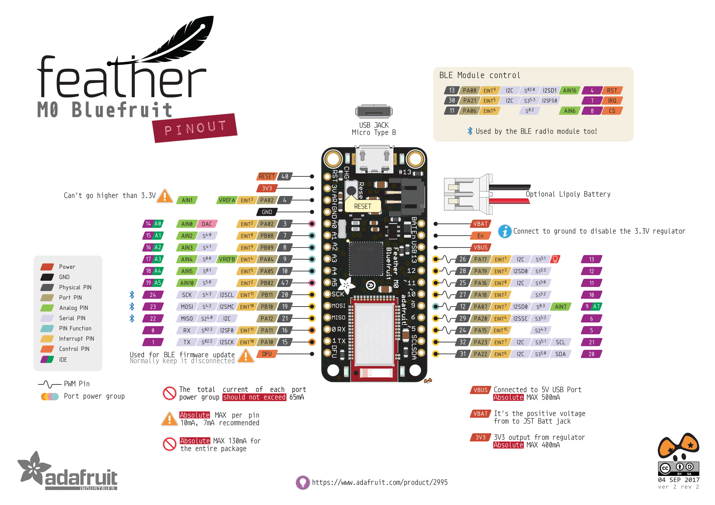


i also can't install adafruit nrf52 due to crc doesn't match due to correupted file for versions 11+ so I only have 10
tried deleting staging/packages, always stops at download of gnueabi-q4
twin ginkgo
ok so i connected the atmega328p to a breadboard and that to my metro how do i upload the script to it (it does have bootloader already on it)
north stream
You're trying to load onto the Metro or onto the ATmega?
deft frost
somehow none of the examples in "Examples for any board" doesn't work
im just trying to get a logger to work with it
 torn pendant
hey guys, im fairly new to electronics, and for an assignment im trying to get a stepper motor to work
however the motor is screeching/vibrating/humming instead of actually turning
im using an arduino nano with the adafruit motor driver


im following that tutorial and my wiring and coding is pretty much identical to that
except for that im using an arduino nano
and that im powering it with a usb cable from the arduino to my computer


thats my setup and code if it helps
and i have this motor https://www.seeedstudio.com/Small-Size-and-High-Torque-Stepper-Motor-24BYJ48-p-1922.html

Small size and high torque, Mainly used in air conditioner louver, small cooling heating fan and Automatic curtains etc
any help would be greatly appreciated!!
thanks
 inland crag
my first guess would be that perhaps the arduino nano doesn't support pwm on those pins?
torn pendant
hm, pwma and pwmb are going into the powered bus, not the arduino nano, unless im missing something
inland crag
I don't actually know anything about the adafruit motor driver, I just know stepper motors are driven by pwm
torn pendant
huh weird that the pwm would be plugged into just a straight 5v then lol
north stream
By running it to 5V, it just provides 100% power.
Perhaps you have your motor pinout wrong?
torn pendant
iv tried pretty much all the combinations
do you think the usb that connects the arduino to my computer is not supplying enough power for the motor to spin?
i do this strategy to test different combinations, and i add a couple extra changes just to make sure
north stream
Hmm, it's a 25Ω motor, so a coil can draw a maximum of 200mA. Two coils would draw 400mA. USB can generally provide 500mA, so that should be fine.
Try changing STEPS to something smaller like 200.
torn pendant
kk il try that out
holy crap
its spinning
wow
thank you so much
lol im genuinely shocked that that fixed it
north stream
I suspect (but admit I didn't verify) that the library scales the speed by the number of steps per revolution. Since the number was so high, it was sending pulses very fast, faster than the motor could act on.
torn pendant
ah, ok that makes some sense
so i should probably find the exact number now, now that i know its not 2048
north stream
Looking at the documentation, it says "Step Angle: 5.625°/32", so it's actually 32 steps per revolution
north stream
So it was trying to go 64 times as fast as expected
torn pendant
haha that would do it. i thought i saw 2048 as steps per rev somehwere but i guess that wasnt it
north stream
I'm a little unsure about the documentation too: 360° divided by 5.625° is 64.
Perhaps it's 5.645°/phase, and 2 phases per full step?
torn pendant
ok with steps at 32, the motor isint spinning anymroe
north stream
You may have to rearrange the wires so it runs properly at the lower speed, might be that it just happened to work at the higher speed with the wiring a little off. Not sure.
torn pendant
oh wait it mightve been spinning actually, and i just didnt notice
but yeah i am rearranging the wires
64 is spinning the motor, but very jaggedly compared to 200 which was smooth
same with 32, if it was spinning, it was very jaggedly
north stream
Might be the wiring, might just be that motor has pretty big steps, so it'll tend to be staccato at low speeds.
torn pendant
Order today, ships today. 108990003 – Bipolar Stepper Motor Permanent Magnet Gear Motor Frame Size 2048 Step 5VDC from Seeed Technology Co., Ltd. Pricing and Availability on millions of electronic components from Digi-Key Electronics.
this is some more documentation on the motor, from the site that i actually bought it from lol
yeah it said 2048 steps per rev which is weird
ok i think maybe the motor i linked earlier was not the same motor... i just googled the number on the motor and i assumed it was the same motor at a different listing
north stream
It could be that it's a geared motor, so while the internal motor is 32 steps/revolution, the output shaft turns more slowly than the motor does.
It's bizarre how many variants there are with the same part number. Some are unipolar, some are bipolar, some are 5V, some are 12V, some are two phase, some are 4 phase.
torn pendant
ah ok thats good to know
so should i trial and error to see which is the smoothest steps per rev? cause the 2048 in the documentation is definitely not gonna work lol
oh ok
so theres 2048 steps per rev
but the code is asking for individual steps
north stream
Looks like the code is setting the speed to 30 as well: might tune for smoothest at full speed.
torn pendant
2048 steps per rev is .176 for a step angle, and according to digikey a .18 step angle is 200 individual steps
i think 200 is about as clsoe as im gonna get, but il test diff speeds too
north stream
It seems like the library is trying to adjust things so a speed of 30 with one motor is as fast as a speed of 30 with another. However, I like your idea of tuning for smoothest motion instead of trying to match the speed of some other motor.
torn pendant
yeah im just gonna do some tuning, that typically works out 😂
btw thank you so much for the help
iv been trying to figure this out a while earlier and i was like my wits end
twin ginkgo
@north stream sorry for the long reply but im trying to load onto ATmega
north stream
Hmm, should be able to use a serial port on the Metro to talk to it, but you might need a level shifter if it's a 5 volt ATmega
raven flame
can I run i2c project from 8pin ATTINY85?
arduino the size of a 555 chip LOL I love it :D
inland crag
Can someone tell me which commands go with which function here? https://github.com/adafruit/Adafruit_SPIFlash/blob/56705756e49e2a41e6927fdd1fc01958ae607f03/src/Adafruit_FlashTransport.h#L31
GitHub
Contribute to adafruit/Adafruit_SPIFlash development by creating an account on GitHub.
 spiral hinge
I just got a hold of a new Arduino Due, but I'm having issues connecting it to my computer.
The plugins are downloaded and installed, so no issue there.
But while I usually work off of COM3, I'm not seeing it. Instead, I'm getting COMs 4, 17,7, and 5 once. When I plug it back in (whether I plug it back in via the (different) USB ports or the different ports on the Arduino itself), the ports change to something entirely different. The most constant one I have is 4.
That and anytime I want to use the Serial Monitor, it either tells me the port is busy or loops error messages that the board can't be read. I've only successfully got the Serial Monitor to run on COM4.
What I'm confused about (besides the above) is that I tested it on a friend's computer to make a little puzzle box and it worked no problem.
If someone would be able to help, I'd greatly appreciate it. Please @ me if possible, as I'll pick up the response quicker. Thank you.
pine bramble
@spiral hinge I don't know what the Due is using. However, one simple thing to do is remove all USB devices that aren't vital (example: a USB thumb drive that's plugged in but isn't in use).