#help-with-arduino
1 messages · Page 48 of 1
 proven mauve
Thank you for the detailed response... I think this is going to take a lot of thought and reading for me to digest properly
 pine bramble
.oO( do few things, but do them well )
Only learn as much as you're willing to put into use ;)
proven mauve
It's hard to figure that part out. Using pretty much .h files for everything really does make me feel like a dummy, and this sequencer program isn't going to be small...
pine bramble
You can be aware of a lot more without knowing it in full
proven mauve
it's just hard to break out of, because using .h makes it easy haha
pine bramble
The problem with C is that by the time you learn enough of it to get by, you're no longer offended by it
 rocky igloo
🤣 🤣
proven mauve
lol
I broke my code apart again and really thought I might have it, but this whole .h and .cpp as opposed to just .h is kicking the tar out of me
rocky igloo
@pine bramble I happen to have an e-book copy of K&R open on my screen this very moment. They comment on several shortcomings of the language but neglect to mention that one.
pine bramble
;)
They're not magic suffixes. .h means nothing whatsoever.
I've seen people put code in their header files.
rocky igloo
I've taken to calling that "The H Programming Language," where the programmer can't figure out how to separate the details of the implementation from what needs to be shared with its users, so they punt and put it all in the header file.
pine bramble
Oh haha that's great.
I wonder if people are being introduced to the C Preprocessor or not.
Maybe they just don't know what it is or how it works. ;)
rocky igloo
That's a real possibility.
I wonder if this leads to an argument about how much people should have to know about what each program does, versus knowing the language as an abstraction.
pine bramble
I'm a big fan of turning on all the compiler warnings, and heeding every last one of them, playing whack a mole until none are left standing.
proven mauve
So, it's definitely treating .cpp and .h differently. I can take the exact same .ino and .h, change the .h to .cpp and change the #include to .cpp and it no longer compiles due to variable not in scope issues, like it's trying to add the cpp before it does ANYTHING else, regardless of where the #include is. I change it back to .h and everything runs fine.
pine bramble
If this is arduino, your .ino is supposed to be empty (comments are okay).
Then include <Arduino.h> at the top of every .cpp file.
That will give you some sense of what a .cpp is and is not.
Make sure you have three of them (or more) just to convince yourself of a few things hard to explain but (somewhat) easy to apprehend in a live programming session.
I can't remember the last time I worried about what order the .cpp files were compiled in. ;)
proven mauve
oiy
pine bramble
Start over with nothing, and build up.
Trying to save a bad coding session isn't worthwhile.
Treat the earlier work as a collection of notes and snippets.
(Unless you're porting; then you may really be stuck working with what you have, haha)
rocky igloo
Lemme get Socratic here. @proven mauve, why would you need to #include a .cpp file? I'm having a hard time thinking of a good reason to do that.
pine bramble
Top down. Bottom up. Middle out. ;)
proven mauve
haha, this is the begging XD
pine bramble
Yeah he's right, including a .cpp is a fundamental misconception (in action).
The compiler finds those for you. No need to tell it that they're there.
proven mauve
timvector, because I'm not very smart on this yet. I was including it when it was .h, and where I included it mattered because I was manipulating global variables. But I'm filling those .h with code and I know it's not 'proper'. So when I changed to trying to use .cpp to be more in line with convention, there's a lot about the compilation as a whole I don't understand and I'm trying to treat it the same as I was.
pine bramble
You're just tricking the C Preprocessor into treating your code as if it were a monolithic single file.
proven mauve
right
rocky igloo
My idea is that a .cpp file is like Vegas. What happens in there stays in there. 😁 Code in any other file doesn't have to know about it and shouldn't.
pine bramble
Why are you offended by a single monolithic file, then?
rocky igloo
But the point of a header file is that what you put in there gets shared with every file that #includes it.
I'm actually old enough to remember that it was a big deal in the 1970s for C to allow "separate compilation" because it let you write modular applications.
proven mauve
So, my understanding is you have arduino code, and eventually you bring everything into your ino, because that's your setup {} and loop {}. So, with the header files it was great, because I could break the program up into functional chunks, and #include them in order because I'm sharing global variables between them (which kinda goes back to me being fairly green). Those global variables are my hangup... because if I want to change to cpp it looks like it grabs those files automatically without needing the include like you're saying, so it tries to get them ready before the global variables are declared and I get an error....
I probably need to be looking into objects and methods maybe, something along those lines, instead of using global variables the way I do
pine bramble
@rocky igloo Well, right, and it's deeply appreciated in conjunction with the Makefile, in that you don't often need to rebuild most of your object files, to make small changes.
Just use extern in your .cpp to reference the variable you declared in another .cpp.
Since you have an empty .ino it starts to sink in that there's no 'the' .cpp there's just 'a' .cpp.
proven mauve
so with extern, it tells it, "this isn't declared yet, but it will be before you need it", and then you have a single declaration that isn't extern?
pine bramble
The main difference is when you add the extern to the definition, you can't initialize.
extern int jagged;
int jagged = 17;
I often misuse the terms myself but since I have the book open here, I'll quote: "There must be only one 'definition' of an external variable among all the files that make up the source program; other files may contain 'extern' declarations to access it."
proven mauve
I see
pine bramble
The first one goes in a secondary .cpp file.
The second one initializes jagged with 17.
What Tim just said was what I meant. ;)
proven mauve
so, with an empty .ino you make setup {} and loop {} in the different .cpps and it runs them for each file?
rocky igloo
Just one definition in one place in one file (your choice which one) but a declaration for every file that uses it.
proven mauve
I see, I see
pine bramble
Keep it simple: create a file called foobar_sketch.cpp and pretend that's your .ino file.
proven mauve
kk
then add .cpps to separate the program, and if they need access to a global variable, extern it
in the files that need access to it
pine bramble
Treat a second .cpp as 'spillover' for something obvious that you understand well, but don't wish to clutter the main sketch.cpp with the details of.
I generally look at something and say 'this got big' and immediately open a new .cpp to contain it.
proven mauve
right
so, that's sortof what I was doing before, but using .h extensions so it worked different, everything needed #included but I could pick and choose exactly where the program started looking at it. This is the project I'm talking about: https://github.com/SandwichRising/Tamaguino-Mega

GitHub
Tamaguino Mega Version based off jakob's project @ - SandwichRising/Tamaguino-Mega
so, in the tamaguino-mega folder, like menu.h for example... all the menu code is there and called as a function in the loop{}.... but I could have just made up an extension and used it like .support or whatever instead of .h and it would have behaved exactly the same is what I'm starting to see
all except .cpp which the compiler gathers up automatically
pine bramble
That's probably about right. I can't say because I stopped experimenting with that a while ago. ;)
proven mauve
man, I hate being dumb on this stuff >.<
I gotta get back to work. Thank you guys for the input... gives me things to chew over
pine bramble
:)
My boss used to say (a lot) 'stop doing that' about a blistering array of things. ;)
pine bramble
My music mentor said never (ever) play anything but your best. No 'practice' because that just reinforces bad habits.
I find I spend most of my time implementing something I know perfectly well how to do, but the physical typing to get it into the real world (from where it sits in my mind) is the bottleneck.
rocky igloo
I wonder if the Arduino environment and the other BlahBlahBlahStudio IDEs make it harder to understand separate compilation. The .o files are hidden in some temporary directory and aren't there to make it clear that code from each source modules lives in different place, and only knows what's in the other modules because of what it sees in your header files.
pine bramble
To be fair, I spend a lot of time in another room or outdoors thinking about the problem, but not so much at the keyboard, unless I'm working out something new and need a model to follow, on-screen.
proven mauve
Alright, thanks again guys. I'll see you around later!
rocky igloo
Good luck with it!
pine bramble
@rocky igloo Learning how to author a Makefile was very important in that process, for me.
rocky igloo
I wrote C for a decade before I ever saw a Makefile. 😁
pine bramble
Haha.
rocky igloo
I've spent time lately running old versions of Unix in an emulator and studying the Bell Labs source code, and you can actually follow the evolution of make through the different versions.
pine bramble
Well you know that http://9front.org never gave up on Plan9.
rocky igloo
For a long time, each project had a script file called run or build or something, and gradually they combined the best ideas from each into a standard system.
pine bramble
I used to author hard-coded .html files and assemble the headers and footers to the variable text using a Makefile. ;)
rocky igloo
I've known about Plan 9 for a while without ever digging too deeply into it--borrowed some source from it a time or two--but only recently learned that it has its own obscure successor, Inferno. https://en.wikipedia.org/wiki/Inferno_(operating_system)
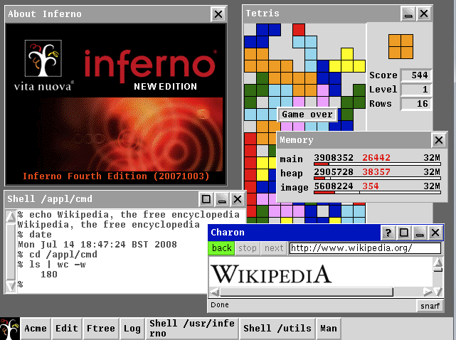
Inferno is a distributed operating system started at Bell Labs and now developed and maintained by Vita Nuova Holdings as free software. Inferno was based on the experience gained with Plan 9 from Bell Labs, and the further research of Bell Labs into operating systems, langua...
pine bramble
I think it's http://cat-v.org/ .. not sure .. has some doco on this.
rocky igloo
Yup, been spending a lot of time on that site!
But focusing on the 1970s work.
I'm very interested in Dennis Ritchie's original C compiler. To me, the code in it says a lot about how he saw the language and what motivated him to add to it in the order he did.
And the compiler implements lists, trees, hash tables, dictionaries, etc, all in straight C and usually without using the language features he had most recently added.
pine bramble
I bet that is a rich and rewarding .. tour .. can't think of the word. Good on you for wanting to appreciate it in the order it was first made. That's some good (accurate) anticipation on your part. I do the same thing with git repositories, and try to commit in such a way that people can follow it from a germ (top down - bottom up - middle out).
afk
rocky igloo
I guess in our own way we do something like deep reading from literary analysis. There's a big picture of where a project came from, who the author or authors are, and why and how it came to be like it is.
I suppose also a lot of meta context around software--tutorials, sample code, style guides, and monographs on good practices.
pine bramble
The webmaster of cat-v.org is a rare archivist. ;)
I think the name is a play on http://catb.org/ which is ESR's site.
rocky igloo
It's quite a collection. Also really good stuff at The Unix Heritage Society, tuhs.org.
I associated the site's name with this: http://harmful.cat-v.org/cat-v/
rocky igloo
Reader reviews include: "I literally could not put this book down until I was done holding it." "If you are pure of heart, you can read this book and not explode." and "7/5, would purchase again."
OK include wasn't quite correct. Those are the only three reader reviews.
pine bramble
Well it's also free on the main site. I never in fact shelled out the cash to Amazon for a hard copy. ;)
rocky igloo
The descriptions of each of the hard-copy volumes even say, "It is very likely outdated."
Have you installed a 9front system?
pine bramble
Yeah I ran 9front for a while.
Back then the limitation was which video cards were supported.
I had a problem develop months later and just didn't solve it. ;)
iirc I had a partition on my hard disk just for 9front.
I would dual-boot.
I also ran it in an emulator in Linux for a while, on the side.
These days I just download and build plan9port and keep it on tap inside Xorg inside Linux. ;)
But 9front is better.
I should probably take the time to reinstall it in an emulator, again.
Just it would eat time I don't want to give up.
(because it's interesting and worth learning)
rocky igloo
So much to do...
It's becoming a running joke, "a fun little project I can knock out in an evening or two."
pine bramble
I've been working on various Forths for a while and have stuck to that agenda.
I just found Dr. Ting's eForth implementation for the STM32F407 discovery board, a few weeks ago.
It's kind of the end-all for me .. I'm a little confused what to do next; so much is done already, in it. ;)
So I'm going to write a .hex outputter inside it, and dump it to a .hex file.
(which is how it got in there, too haha)
I want to see what I can do by the way of modifying it in-situ, then exporting to .hex from inside it (just like a regular hexdump - a session with a serial comm program like putty (minicom in my case).
I'm thinking I can switch it over to the correct port pins assigned to TX and RX (it's on SDA and SCL right now, as silcscreened on the STM32F405 Express. ;)
That way, anyone who tries it can still use SDA and SCL (as labeled) on the Express board.
(I don't think it really matters much)
There's usually a reason why things are done the way they got done, so I thought I'd go ahead and 'correct' this problem.
proven mauve
@pine bramble @rocky igloo I'm getting it. I just emptied out my ino and got it to compile using .cpp's and .h's.... It's weird how it's like hitting a brick wall all up until you look at it once and things suddenly make sense and you can't figure out how you didn't see it before
pine bramble
There you go. ;)
Nick Gammon wrote all this up, by the way.
(That's how I heard about it)
proven mauve
I thought I could put my variables in the headers but was running into double declaration problems, even with #ifndef statements, so I'm going to have to get it a bit more, but it's a start lol
pine bramble
Working out the consequences of what he said is up to you; there's more than one way to do it. ;)
(My .ino is always blank even though I use libraries; I don't quite know why it works out fine but it does)
@rocky igloo @rocky igloo I'm really gone now. Thanks for the.
fades
 low ingot
am I going crazy? For some reason, I'm unable to use iostream with arm-none-eabi
proven mauve
@pine bramble @rocky igloo @surreal pawn You guys are awesome yet again, you got some concepts to sink in and now I am not having problems dividing my program up into .cpp's, I understand some of the compiling concepts so much better now and am off and running.
@acoustic nebula You are also super awesome, your library is great. It was really easy to add in a single boolean variable to control turning on and off buffer dumping or using direct rendering instead. With the buffer dumping turned off, I have the samd doing 400,000 cycles a second with the screen refreshing at 20fps, and with buffer dumping it's about 225k CPS. All while running the I2C bus at 400kHz and transferring potentiometer and button data over it from an external 328P as well as the screen (the 328p is running with the 8mhz internal clock at 3.3v, so when I get around 800kHz on the bus I start getting hangs). In a nutshell, I'll really be able to build off of this, and am really looking forward to getting this MIDI sequencer going.
rocky igloo
@proven mauve Way to go! It's great that you're taking it seriously and paying attention to the quality of the code you write. Best of luck with the project. 😄
 jolly goblet
I am trying to build a prototype that uses a k-thermocouple to remotely measure the temperature of an air dryer via bluetooth,
My concern and why I'm reaching out to you as, the high heat point is 300 degrees fahrenheit, how do I avoid the electronics overheating from the k-thermocouple?
What electronics are suggested?
 narrow thorn
longer wires?
 tough snow
A thermocouple is designed in its purpose to not transmit heat to the electronics connected to it. So long as the electronics are not in the path of the heat inside the air dryer, they should be fine.
pine bramble
#include <LiquidCrystal.h>
#include <FastLED.h>

#define LED_PIN     5
#define NUM_LEDS    144

// initialize the library with the numbers of the interface pins
LiquidCrystal lcd(7, 8, 9, 10, 11, 12);

CRGB leds[NUM_LEDS];

void setup() {
  // set up the LCD's number of columns and rows:
  lcd.begin(16, 2);
  // Print a message to the LCD.
  lcd.print("hello, world!");

  FastLED.addLeds<WS2812, LED_PIN, GRB>(leds, NUM_LEDS);

}

void loop() {
  // set the cursor to column 0, line 1
  // (note: line 1 is the second row, since counting begins with 0):
  lcd.setCursor(0, 1);
  // print the number of seconds since reset:
  lcd.print(millis() / 1000);

  for (int i = 0; i <= 143; i++) {
    leds[i] = CRGB ( 0, 0, 255);
    FastLED.show();
    delay(40);
  }
  for (int i = 143; i >= 0; i--) {
    leds[i] = CRGB ( 255, 0, 0);
    FastLED.show();
    delay(40);
  }
}```

the print works fine without any of the LED code. when the LED code is added the print only gets updated every 20/30s . any ideas?removing the delays it still only updates every 2-3s
tough snow
@pine bramble So, here's what I see at first.
Your print will happen once per loop.
But, inside that loop, you have two separate for loops.
So, the first for loop needs to run... 143 times before the second for loop runs another 143 times.
And then the print will happen again.
Er, my bad. 144 times. Silly zeroes.
So, 288 loops with a delay of 40 is 11.5 seconds worth of just delays. That's not counting any amount of time that the FastLED library takes.
pine bramble
ok that makes sense
tough snow
How do you improve that? I'm not sure. I don't know precisely what you're going for, nor have I poked at coding at all recently. But that's what jumps out at me at first.
pine bramble
i haven't messed with my arduino in a while and picked up a strip of neopixels and i already had a 16x2 LCD screen. was gonna try to wire up a button and come up with several patterns to cycle through and just noticed that 'bug' while wiring everything up.
hooked up my led's with external power supply and arduino on a seperate one and the things freak out. if i hook them directly up to arduino with a shared powersupply it works fine
tough snow
The LEDs should be on an external power supply - Just make sure the grounds are connected together
pine bramble
ah thats what the problem is. guess i should read about these, looks like i need a couple resistors and a cap
tough snow
There's a nice NeoPixel guide on the Adafruit Learn Center
Never really fiddled with NeoPixels myself, though
pine bramble
yes im reading now. says it wants a 300-500 ohm resister on the data line. i only have 4.7k and 10k ohm ones 🐼
 steady badge
sorry to bother you guys, but if anyone can please help me my arduino ide on linux changed ports randomly
i have been trying to figure it out on my own, but after 4 tutorials online i still havfent found what I need to fix the problem
I found that my arduino is on dev/ttyACM0
and I read online that I need to change the config file in arduino, but there are actually a few config files for (edit) the ide and I don't know which one to use
tough snow
@steady badge In the IDE, you might be able to select "Port" under "Tools" but I'm not on linux so I don't know for certain.
I know that I have had boards that, under Windows, would end up being assigned a new number frequently, which was super annoying, but it was just a matter of selecting the port in the IDE, no file editing needed
steady badge
there are 32 ports
and i went through 20 ports one by one
i guess i will go through the last 12 lol
@tough snow i'm getting an error avrdude: ser_open(): can't set buffers for
and then "\.\COMxx"
is that the error you get for having the wrong port
tough snow
I haven't fiddled with that end of the ARduino IDE. For me, it only shows ports that have things on them.
steady badge
I dual boot windows and I just used it there
 bright nest
Is there an Arduino board that has either 8+ analog pins or a separate pin for SCL and SDA?
tough snow
@bright nest The Mega has a pile of pins. But what are you trying to do?
bright nest
I want to use the 12 channel servo controller, but it requires an SCL and SDA pin. I need a board that has at least 7 analog pins because my project uses 7 force resistors, which each require an analog pin. The Arduino Nano fits the analog pin requirement, but it needs to use several of the analog pins in order to be compatible with the servo controller, which leaves me with an insufficient amount of analog pins. I've done some research and it looks like the Arduino Mega is a good fit, but it's also pretty expensive....
sorry it took me a while to type that out
tough snow
No worries
So, I see what you're trying to do but, and this may sound silly, what are you trying to do?
Or, put better, why are you needing the force resistors?
bright nest
Okay well this might take a while to explain LOL
tough snow
Sure!
bright nest
So I'm a senior in high school, and one of things that my school requires us to do is a senior community service project that involves the engineering concepts we've learned throughout high school, which means we have to actually build something. I foolishly decided on building a Harry Potter-themed bookcase that housed the Harry Potter series, complete with an animatronic Sorting Hat that reacted every time you interacted with a book. The hat requires servo motors in order to move, which explains the motor controller, and the force resistors are to signal whenever a book is taken out or put back.
Also, my teacher wanted us to include a working mechanical door on the bookshelf, just to add to the complexity, so I figured I could 3D print a wand that held an IR emitter and attach an IR reciever somewhere in the hat so that the door would open with the flick of a wand like in Universal Studios.
I dreamed a little too big, and the project is due next week. I have the skeleton of the hat printed and assembled, but I've realized that I needed a lot more than a couple of hobby servos to actually get it to work correctly.
tough snow
Oh. Well. I have known that.
tough snow
You only need to know if a book has been moved, right?
bright nest
yeah pretty much
tough snow
Because, realistically, you could use digital pins for figuring if a book has been moved. Not 100% sure if you can use your force resistors for that, if you already have them
If not, you can use one of a number of other methods of detection.
bright nest
I wasn't sure if the force resistors would be compatible with digital pins...
tough snow
They're strictly analog devices, right?
bright nest

FSRs are sensors that allow you to detect physical pressure, squeezing and weight. They are simple to use and low cost. This sensor is a Interlink model 402 FSR with 1/2 diameter sensing ...
tough snow
Digital returns a 1 if the voltage is above a certain point, and 0 if it's below that point. The question is if the resistor would go low/high at the right points
Those are really cool
bright nest
I don't know how I would test that
bright nest
Yup. Seven of them for about $50
tough snow
OK. Then I will suggest to you an item that will solve your problems without having you re-purchase anything
And that is: The multiplexer!

The SparkFun Multiplexer Breakout provides access to all pins and features of the 74HC4051, an 8-channel analog multiplexer/demultiplexer. The 74HC4051 all
This lets you use 8 analog devices on a single analog pin.
You control it with three signal pins to select which channel it is reading
tough snow
Makes programming a little bit more complex, but not a ton
And means you can use a lot more in the way of microcontrollers and not have to worry about the size or cost of a Mega
bright nest
but what if i need to read the output of all of the resistors at relatively the same time?
oh i see
i would just have to loop through all of the pins and decrease the delay in between so it loops really quickly?
tough snow
Programatically, you'd have to cycle through them anyway. This just adds a step for changing the MUX between, which isn't a lot of time
Yep
I've used one of them for an array of Hall Effect Sensors
There was actually a point where I was reading things too fast and the information was getting screwy
bright nest
Interesting. Once I get it I'll start experimenting to see if I can get everything working the way I want it to. Thank you so much for your help!
If I ever need some programming assistance, is it okay if I ask you?
tough snow
Programming, I'm terrible on
Well.
That's a lie.
I don't like programming so I do as minimum as necessary, so there's a lot of gaps in my knowledge
However, this is the place to ask for help. Plenty of people know programming and can help out
bright nest
Awesome. Thank you again!
tough snow
Not a problem! Happy to be of assistance
 acoustic nebula
@bright nest you should have enough analog pins to do it without the multiplexor
You can do I2C on any 2 GPIO Pins
the Nano sounds like it has enough I/O to do the job
 marsh sleet
Hello, while i was doing my IT homework, i came across a question that left me confused. We have to use a null terminated string, we have a couple of sentences (kinda like the lorem one but in french) and we have to count how many sentences there is in that text
At first i wanted to use the strchr operation
but i didn't understood how it worked
acoustic nebula
you can use strlen() and keep advancing a pointer with the length of each string (+1)
marsh sleet
but strlen only count the number of characters in a string right ?
acoustic nebula
e.g.
char *pText;
while (pText[0] != 0)
{
printf("sentence = %s\n", pText);
pText += strlen(pText) + 1;
}
// assumes there's a double terminator on the last sentence
marsh sleet
sorry, i just started to learn about the strings and null terminated strings, and i don't understand fully the usage of all the operations it seem
so strlen count the number of characters until it find a new sentence ?
acoustic nebula
you're normally given a pointer to the start of a C-String. You know you've hit the end when you reach a 0x00 byte. strlen gives you the length of the string from the start until it hits the 0x00
e.g. 0x41 0x42 0x43 0x00 ("ABC")
strlen() would return 3
marsh sleet
okay, i understand that (i also have to show the number of characters in the text and i used strlen), but i don't see how that would help me find the number of sentences
i first though that i would only need to count how many "." are in the text
which is why i tried to use strchr
but it seem that's it's harder than i though
acoustic nebula
if each sentence is a zero-terminated string and they're stored one after the other, my code above will work; just add a counter in the middle (e.g. iSentenceCount++)
marsh sleet
okay i'll try that thank
one question, i need to use ch[] = "text", but that will also work right ?
like char ch1[] ="text";
acoustic nebula
yes, the compiler will turn this:
char text[] = "ABC";
into this:
0x41 0x42 0x43 0x00
marsh sleet
okay thank you
acoustic nebula
you may get warnings depending on how you define your constant char strings
marsh sleet
it work perfectly thank, but i never understood the usage of the * before/after variable
like the char *pText;
 north stream
That means that the pText variable isn't a character, but a pointer to a character.
C uses pointers for arrays (and strings are arrays), so you'll see a lot of that kind of thing, as well as things like ```c
char message[] = "This is a string";
char * pMessage;
for (pMessage = message; *pMessage != '\0'; ++pMessage) {
}
It turns out that message and pMessage are both pointers to characters, so the pMessage = message assignment is both legal and reasonable.
marsh sleet
oh okay thank you
proven mauve
ugh, I forgot I have to brush up on pointers and you guys reminded me
@acoustic nebula got a working menu system written in now and I'm still getting an easy 600k cycles per second. It jumps to 1 million if I go to a page that only has a title
acoustic nebula
👍
marsh sleet
Hello again, need a little help with a function, i wanted to use the strcspn operation, the problem is that i don't know how i can make it start (in the string) from a certain point
technically it should show 3
but it give me this
 vast cosmos
why would you expect it to show 3 ?
the first character in ch1[3]="4567s" is "4", which is not included in the character set ch2="s", so it only spanned that one single character, hence 1.
marsh sleet
i though it would show me when the character of ch2 appeared in ch1
It seem i didn't understood the purpose of strcspn
vast cosmos
it returns the index of the first character NOT in ch2
from the manpage: In other words, it computes the string array index of the first character of s which is not in charset, else the index of the first null character.
marsh sleet
oh... so i would need to use strspn ? (i'm using french documentation, so i'll try to see on manpage)
vast cosmos
well, what are you trying to accomplish? find the index of the first occurrence of a single character?
marsh sleet
find at which character the string ch2 is in ch1
vast cosmos
the traditional C method for that is strchr()
ch2 will be a string? not just a character?
in that case, the traditional method is strstr()
marsh sleet
well, it is just a character, but isn't it the same since it's a ch[] ?
vast cosmos
no, a char is different than a char[]
vast cosmos
it will return an integer index
marsh sleet
so then i could use the atof function to get a int from the integer index right ?
north stream
I think strchr() returns a pointer to the matching character, not an index
index() returns the index of the first match
vast cosmos
oh right @north stream. so to get the character returned, you would simply dereference the return value like so: char *ch = strchr(str, c); if (NULL != ch) { Serial.println(*ch); }
north stream
They both find the first matching character, but index() returns the index of the match (or -1 if no match), where strchr() returns a pointer to the match within the string (or NULL if no match)
marsh sleet
index is the exact thing i was searching for thank you so much
vast cosmos
so i just submitted my first library (well, 3 libraries) to the Arduino Library Manager index. anyone have any idea how long that takes to get processed and posted?
north stream
Cool! I have no idea how long such things take, but I would guess it's pretty variable.
vast cosmos
i'm also curious how making updates works too. how they know which revision to use as the latest and how frequently those are polled
quite the PITA to refactor library code to meet their requirements. e.g., source file placement, metadata location and format, etc. it certainly could have been worse, but its something to be aware of -before- finishing the software implementation 🙂
newest official arduino release 1.8.10 now has a "depends" attribute in the library metadata that allows libraries to explicitly call out other libraries (in the Library Manager index) it depends on, each of which will be prompted to the user for download if they don't already have them
you may have noticed that if you've done any library updates recently. a lot of Adafruit's library packages are starting to utilize that "depends" attribute properly
so you'll get a dialog prompt to download some other library when trying to update
north stream
Hmm, sounds like a good idea, but some extra work, especially if you didn't design for it.
vast cosmos
no idea if it operates recursively, like a proper pkg manager (e.g. dpkg/yum), but it reduces some of the failed compile/link surprises!
 fluid wagon
Link errors are good for the soul
marsh sleet
when you said the function index(), you mean indexOf() ?
i can't find any documentation of index() with arduino
rocky igloo
From Linux man pages:
The index() function returns a pointer to the first occurrence of the character c in the string s.
The strchr() function returns a pointer to the first occurrence of the character c in the string s.
POSIX.1-2008 removes the specifications of index() and rindex(), recommending strchr(3) and strrchr(3) instead.
rocky igloo
Then I guess it won't. The build system gets the last word on that. 😁
Does strchr() work?
marsh sleet
it does, but i need to get a int, and strchr give me a pointer
maybe i can convert it to a int
rocky igloo
Pointer arithmetic -- subtract the address of the string from the return value.
marsh sleet
so when i have my pointer, i just do - Text[] ?
rocky igloo
You don't need the [].
marsh sleet
but i can't subtract a char from a char right ?
rocky igloo
#include <stdio.h>
#include <string.h>

int main(void)
{
  char s[] = "abcdef";
  char *res = strchr(s, 'c');
  printf("%ld\n", res - s);

  return 0;
}```Output is "2".
vast cosmos
why do you need an int @marsh sleet ?
marsh sleet
it was because i wanted to count (using a != operator with a while), but i guess a char could work
vast cosmos
also, a simple loop would work: char s[] = "abcdef"; char *c = (char *)s; for (int i = 0; NULL != *c; ++i, ++c) { if (*c == 'c') { Serial.printf("found 'c' at index %d\n", i); } }
but @rocky igloo 's solution is probably the best solution
(although i think your format flag needs to be unsigned)
marsh sleet
his method worked perfectly, but i now need for the strchr to start searching after x
so i though that i could use strchr(s[5], 'c'); for example
but my Serial told me otherwise
rocky igloo
Or ```c
#include <stdio.h>
int main(void)
{
char *p, s[] = "abcdef";
for (p = s; *p && *p != 'c'; ++p);
printf("%ld\n", p-s);
return 0;
}``` 😁
marsh sleet
it give me the result like the +5 don't exist
marsh sleet
like that ?
vast cosmos
nailed it!
rocky igloo
Oh, I think I see what you mean
You're searching starting at character 5 but still subtracting the address of the start of the string.
Serial.println(res - ch1 - 5);
It worked thank 😄
rocky igloo
NP
vast cosmos
to be clear what you're intending, parentheses might help, as in res - (ch1 + 5). that way it matches what you have in strchr()
marsh sleet
it does seem better than have multiple minus in row
rocky igloo
That's reasonable.
vast cosmos
its just a readability thing
marsh sleet
thank you two you really helped me on that one
rocky igloo
Good luck with the rest of it.
 rotund condor
im having trouble using the timer interrupt function
I need a interrupt to occur every .864 seconds but whatever I do I can't seem to get the math right for TCNT1
does anybody have a formula i can double check is the same as the one I'm using
 surreal pawn
@rotund condor On what device?
rotund condor
atmega 328 on the uno
surreal pawn
16mHz?
  TCCR1A = 0x00 ;
  TCCR1B = 0x00 ;
  TCNT1 = 0x0000 ;
  TCCR1A = 0xA2 ; // fast 16 bit PWM
  TCCR1B = 0x1C ; // prescale /256
  ICR1 = 54000-1 ; // 16000000/256*.864
  TIMSK1 |= 0x01 ;  // overflow int
at least that's my guess from https://forum.arduino.cc/index.php?topic=452021.0
Timer1 interrupt exactly one second on 16 Mhz
rotund condor
let me try that
surreal pawn
also http://www.gammon.com.au/timers looks worth reading
Gammon Forum : Electronics : Microprocessors : Timers and counters
surreal pawn

@pine bramble are your filenames 8.3?
the file separator is a forward slash, so "folder/test.mp3" should work
Open-source electronic prototyping platform enabling users to create interactive electronic objects.
 neat oar
hell, I was wondering what type of led strip this is ? It is hard to since there is no label
hello*
also how do I connect this with Arduino and the power supply
 barren scaffold
If they're anything like Neopixels, then https://learn.adafruit.com/adafruit-neopixel-uberguide/basic-connections may help there. And that page has a big warning to look for the + and - labels on the end of the strip before connecting to anything, since pin configurations can vary.

Adafruit Learning System
Everything you always wanted to know about Adafruit NeoPixels but were afraid to ask
 neon trench
Hi. I'm trying to migrate a hardware project (8 x 8 x 8 LED cube using the jolliCube board) from an Arduino Uno to an Adafrruit Feather nrf52840. The cube works fine with the Uno, but I'm hoping that after I get things working with the Feather, I can eventually add Bluefruit app support. Unfortunately my engineering + Arduino knowledge is so basic that I'm stuck on getting even the basic test sketch to work. In addition to 5V/USB power + GND, the Uno uses three pins: 10 - for SPI, 13 for SCK, and 11 for MOSI. I first tried wiring things up on the Feather using Feather's 10, 11, and 13, but the test sketch lit up most of the LED lights with none of the expected animation. I then looked at the schematic at: https://learn.adafruit.com/introducing-the-adafruit-nrf52840-feather/downloads I don't really know enough to read these properly, but I noticed an SCK pin, so I moved 13 to SCK. This lit up all of the LEDs, but still no animation. The Arduino sketch #includes a standard SPI.h library, and the main sketch has only one pin definition: int SPI_CS = 10; to control the MAX7219 on the jolliCube board. I've selected the Feather board & port, and the sketch seems to be uploading. I'm wondering: 1) do I have the pin wiring wrong as I try to move from Uno to Feather nrf52840 Express? 2) do I need to #include any additional libraries to get the Feather to work, or will I need to sniff in these libraries & make additional pin re-mappings to go from Uno to Feather? Again, I pretty much know nothing about the engineering side of things, so any help in trying to understand where I've gone wrong & what needs fixing is most appreciated. Thx! J

Adafruit Learning System
The first Bluefruit Feather with USB and CircuitPython support
And if it's useful, here's a link to the test program: https://gist.github.com/gallaugher/6565129884d0661abcd47b4c97b08bba

Gist
jolliCube test sketch for Arduino. GitHub Gist: instantly share code, notes, and snippets.
north stream
@neat oar Looks like it might be a DotStar/SPI style LED strip, just guessing from the markings. If so, Di would be "data in" and Ci would be "Clock in". Unsure about "St" and "Li".
rocky igloo
@neat oar Can you read anything off any of the integrated circuit packages along the strip? If they say something like "SC6803" or "LPD6803," LED strips with that controller chip have been known to be labeled that way. Apparently they've been around for a while. https://github.com/adafruit/LPD6803-RGB-Pixels

GitHub
Controlling library for strands of these pixel dots - adafruit/LPD6803-RGB-Pixels
neat oar
No I wasn’t able to find any label, just found the led strip in the school
 odd fjord
there is this item - not quite the same but has SI and LI https://learn.adafruit.com/hl1606-led-strip/wiring
 rocky igloo
@odd fjord Nice find there. At least that establishes that they stand for strobe and latch, which is something.
 wraith current
@neon trench You should be using the pins on the feather labeled MO and SCK, not 11 and 13. Those are the ones defined for the board and used in the SPI library. Pin 10 should work fine for the CS (chip select).
pine bramble
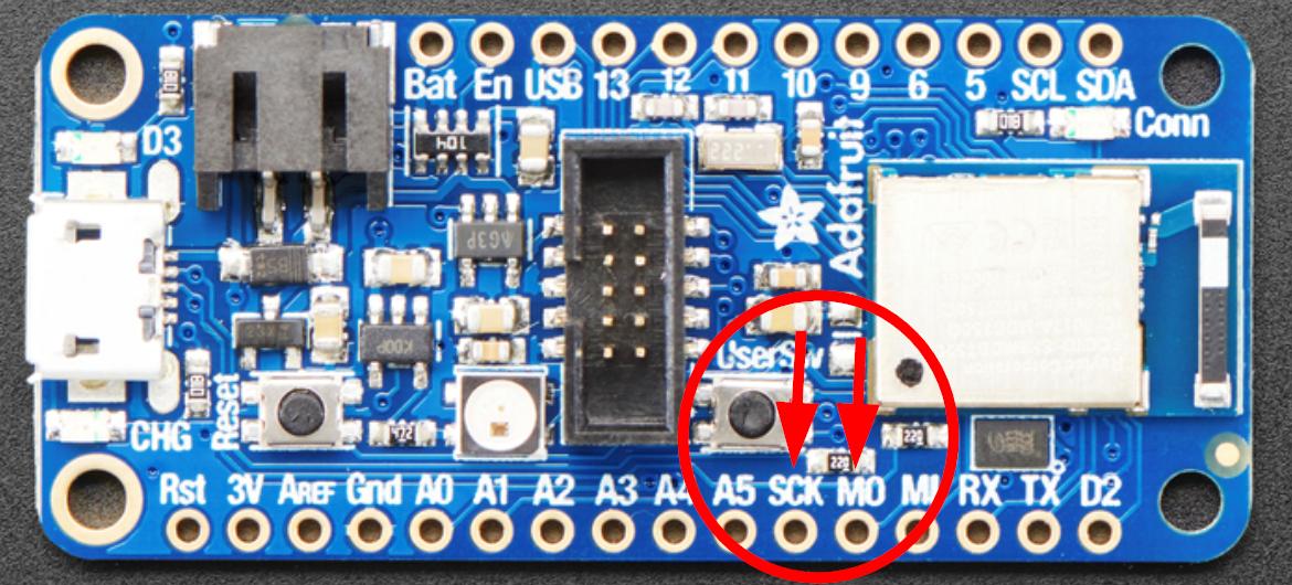
for further clarification @neon trench 👍
the SPI library will automatically use these pins
 copper oriole
hello, is there anyone who could kindly help with what to buy to get started? i have a particular project involving a solenoid
wraith current
@copper oriole that's a bit vague
probably need something like this to drive the solenoid https://www.adafruit.com/product/3191

A Feather board without ambition is a Feather board without FeatherWings! This is the Power Relay FeatherWing. It gives you power to control, and control over power. Put simply, you can now ...
copper oriole
@wraith current I'm basically trying to copy this video https://www.youtube.com/watch?v=nwVRMU9grSI (mosfet powering solenoid switched by arduino). But I'm confused on which power supply to get and how to connect it to the breadboard, and whether you need another one for the arduino. I'd like it to run just plugged in to the wall.

My complete guide to using your Arduino to control a solenoid! Building a custom pinball machine sent me down the rabbit hole of learning how to control solenoids with a micro controller. It turns out there are a few gotchas to watch out for.
NOTES
- The solenoids used are ...
I'm planning on running it for days at a time, so would like a safe and robust connection for the power supply
wraith current
The solenoid used in that video is 12v and the arduino can take 12v if powered from the barrel jack, so just get a 12v power supply. Don't skimp on the Amp rating though, you need enough power so that the selenoid doesn't drop the voltage too much and brown out the Arduino.
copper oriole
Does that mean to use a wire to connect the Arduino Vin to the breadboard?
wraith current
yeah, that should work. The Vin pin is connected directly to he barrel jack, so you can power the whole thing via the barrel jack
copper oriole
If I get a solenoid with higher voltage, would I then use a separate power supply, and connect that to the breadboard using something like this? https://www.adafruit.com/product/373

This power jack is designed to fit 2.1mm power plugs snugly and securely. Perfect for adding a power connector to your project. We went for the more expensive "thin pin" type which ...
@wraith current does this look like an adequate sparkfun order? thanks for your help.
added some diodes.... and a multimeter
wraith current
does the power supply have the right barrel connector ?
copper oriole
i just realised that... it has ATX connector, maybe I should just get something off amazon?
wraith current
the sparkfun version with barrel connector is out of stock. I assume you're trying to do this without having to solder ?
copper oriole
yes, ideally
i could just get this thing https://www.amazon.com/TMEZON-Power-Adapter-Supply-2-1mm/dp/B00Q2E5IXW
wraith current
you could get this https://www.sparkfun.com/products/14933 . The solenoid will probably still work on 9v or you could try to find a 9v solenoid.

This power supply is a highly reliable desktop style single-output green adapter. It is designed with a low/no load power consumption (less than 0.075W) an
copper oriole
i think the solenoid won't be powerful enough at 9V. 12V may not even be enough. But going 12V allows both the arduino and solenoid to be powered from the same supply if it happens to be enough
Do you think the amazon power supply would work?
the solenoid supposedly draws 650mA at 12V, so 2A should be enough
wraith current
Technically it should work, but it looks a little bit small to really be able to supply 2A
Should be ok.
copper oriole
Well apparently 1A will do
Don't really want to spend too much on this one in case I end up needing to buy a separate 24V or 36V supply for the solenoid
Then it would only be powering the arduino which i assume is tiny current
wraith current
What's the solenoid going to push anyway ?
wraith current
oh cool.
wraith current
no worries. Glad to help.
would love to see a video of the finished product mashing the buttons though 😉
copper oriole
Ok I will add you and send when happened
The buttons are custom product I am making
Mass production!!!!
north stream
If you're using an ATX power supply SparkFun offers this to use it as a general purpose power supply https://www.sparkfun.com/products/12867

You don’t have the power? Well, there’s no need to ask Scotty – the SparkFun Benchtop Power Board Kit has your back. This board will let you take adv
copper oriole
@north stream thanks but i think i go with the barrel connectors, my brain is too small for soldering
also what other cute things can i bundle into this sparkfun order
north stream
I don't think the barrel jack you posted will work with a breadboard, it's designed to be soldered. For breadboard use, I recommend something like https://www.adafruit.com/product/368

If you need to connect a DC power wall wart to a board that doesn't have a DC jack - this adapter will come in very handy! There is a 2.1mm DC jack on one end, and a screw terminal block ...
There's also https://www.adafruit.com/product/373
This power jack is designed to fit 2.1mm power plugs snugly and securely. Perfect for adding a power connector to your project. We went for the more expensive "thin pin" type which ...
Oops, I'm wrong, that's the one you posted. Yeah, that will work
copper oriole
im getting this one https://www.sparkfun.com/products/10811

This DC power jack/connector is just like the other one that we carry except that it's terminated with breadboard-friendly pins instead of wide solder term
its the same i think ye
thanks though
its cool what u can make without even soldering these days!!!
neon trench
@wraith current & @pine bramble huge thanks! The test sketch is now working on the Feather and is driving the jolliCube & the lights are cycling through, top to bottom, as expected. Unfortunately I can't get the demo sketch with animations running on the Feather, though. It runs fine on the Uno, but I get the error output from Arduino shown in the gist, below. https://gist.github.com/gallaugher/96fb2079be5cfd33be5163d03d3ba536 The exact same sketch runs fine on the Uno if I switch the wiring, select Uno as the board, and select the proper Uno port, but doing the same with the proper Feather nrf52840 board & port gives me those errors. While I've been able to cobble together code modifications in Arduino in the past, I'm not savvy enough with the platform to get a sense of what's happening here. These errors look like syntax errors to me, but apparently not if they run fine & unmodified in the Uno. I've also included a screenshot below - same as the first part of the error output & copied into the gist at the URL, above.
Gist
Errors trying to run MD-Cubo arduino sketch that works for Uno, on a Feather nrf52840 - Error_Output
north stream
Looks like either you need another header file to define those things, or your CPU has them with different names, and you'd have to adjust the code to match.
surreal pawn
it won't call whichsong() inside of the string like that
surreal pawn
I don't understand what you're asking
I don't have a arduino within reach to test on, but here's what you might do instead
int whichsong(int thissong) {
  int result = thissong + 1;
  if (result > 5) {
    result = 0;
  }
  return result;
}

void setup() {
  Serial.begin(9600);
}

void loop() {
  int thissong = 1;
  String path = "songs/";
  path = path + whichsong(thissong);
  Serial.println(path);
}
When I did something like that, I went through the files and counted how many were the right type. Then I'd pick a random number in that range, go through the files until I got to that one, and play it. That meant I didn't need to keep the list in memory, with the tradeoff that I would have to go through the files again every time I wanted to play a new track.
surreal pawn
@pine bramble the string constructor can convert numbers to strings. the concatenation line should auto-convert the number to a string but it could be string path = path + String(whichsong(thissong)); instead to be direct or maybe you want to pass other arguments to the string constructor
you could also just lookup in an array:
const int num_files = 4;
const char* const mp3files[num_files] PROGMEM = {
  "foo/0.mp3",
  "foo/1.mp3",
  "foo/2.mp3"
  "foo/3.mp3"
};

void setup() {
  // put your setup code here, to run once:
  Serial.begin(9600);
}

void loop() {
  int n = 0;
  while(true) {
    // n should be from 0 to (num_files - 1)
    Serial.println(mp3files[n]);
    delay(100);
    n++;
    if (n >= num_files) {
      n = 0;
    }
  }
}```I'm not sure the names in an array approach would work since it has to figure out some of the filenames on the fly
 ruby rampart
hmm, the page doesn't say, but I'm assuming the ItsyBitsy nRF52840 can be powered at 5v 1A?
oh, there, it says 3.3v
neon trench
OK, when hunting in the code it looks like the errors are coming from a file deep in the library named "MD_Cubo_8x8_ICS574.cpp". And when I look at the code, this seems to be the area where the errors are triggered. What's happening here is definitely beyond my expertise, but I'm hopeful someone might recognize what this refers to & can point me to an appropriate reference to make changes for the Feather nrf52840. Thanks:
// everything works direct on the uP ports.
void MD_Cubo_ICS574::begin(void)
{
int i;
for(i=0; i<14; i++)
pinMode(i, OUTPUT);
// pinMode(A0, OUTPUT) as specified in the arduino reference didn't work. So I accessed the registers directly.
DDRC = 0xff;
PORTC = 0x00;
// Reset any PWM configuration that the arduino may have set up automagically!
TCCR2A = 0x00;
TCCR2B = 0x00;
TCCR2A |= (0x01 << WGM21); // CTC mode. clear counter on TCNT2 == OCR2A
OCR2A = 10; // Interrupt every 25600th cpu cycle (256*100)
TCNT2 = 0x00; // start counting at 0
TCCR2B |= (0x01 << CS22) | (0x01 << CS21); // Start the clock with a 256 prescaler
TIMSK2 |= (0x01 << OCIE2A);
}
north stream
The port changes are probably fairly simple (the pinMode() comment gives a clue what they're intended to do, so you can probably replace those with pinMode()). The PWM/timer configuration is likely to be more tricky.
Looks like it's supposed to interrupt at a regular rate (every 1.6ms, assuming the Arduino was a standard 16MHz one).
wraith current
@neon trench I think you have some weird extra cruft code that you don't need. The jolicube is commuincating over SPI so there is no need to setup all those pin outputs nor initialize an ICS574 chip since the jollicube does not use an ICS574
you can probably get away with editing that function by deleting all of its contents and going along your merry way.
Mainly thats ok because that function never gets called in the first place.
pine bramble
Hey everyone - I'm new here so not sure if this is the right channel but I am taking my EdgeBadge through the examples and am trying magic_wand_arcada. When the code is done uploading to the board, I get this error - does anyone know what I am doing wrong?:
No filesystem found! For QSPI flash, load CircuitPython. For SD cards, format with FAT
magic_wand just works as expected. I am working on OSX. Thanks in advance
FYI I also had some trouble doing this example: https://learn.adafruit.com/tensorflow-lite-for-edgebadge-kit-quickstart/customized-wave-demo
It required 2 resets to get the usb drive to appear.
surreal pawn
did you put the bitmaps onto the CIRCUITPYTHON drive as described in the learn.adafruit guide?
if not, maybe it's complaining it can't find them. The demo should still work, but it will just show a letter on screen instead of the bitmap + sound
pine bramble
I had to double reset to get a drive to put the bitmaps on - not single reset as shown in the example. The drive is called PYBADGEBOOT and contains CURRENT.UF2, INDEX.HTM AND INFO_UF2.TXT - its not empty as shown in the example. If I double reset and put those files on the drive, then reset, I get the original error 'No filesystem...'
surreal pawn
no, that's the wrong drive. PYBADGEBOOT and the UF2 files are how you'd upload new programs from things that aren't arduino, such as updating circuitpython or putting a game from makecode on
you can upload the circuitpython for pybadge .uf2 file to get the circuitpython drive, but you should also be able to get the circuitpython drive by uploading an arduino sketch with the usb library set to tinyusb perhaps with some additional code
pine bramble
I have tried uploading this one yesterday but I got the same result - is this what u mean? adafruit-circuitpython-edgebadge-en_US-5.0.0-beta.2.uf2
surreal pawn
sure, if you copy adafruit-circuitpython-edgebadge-en_US-5.0.0-beta.2.uf2 to the PYBADGEBOOT drive that shows up when you double-press reset then it will reboot to circuitpython, and the circuitpython drive will appear
OR, you can upload the arduino sketches for the edgebadge demos you were trying, but you need to change the USB stack to TinyUSB https://learn.adafruit.com/tensorflow-lite-for-edgebadge-kit-quickstart/setup-for-compiling-examples

Adafruit Learning System
Get going quickly with your TensorFlow Lite kit!
oh, and that specific error you were getting might be because the filesystem can only be mounted in one place: Either to your computer, or to the software on the badge
so after you copy the files to the circitpython drive you need to safely remove or eject it then reboot the badge (you can leave the usb cable connected) and then the images/sounds should work
pine bramble
When I upload adafruit-circuitpython-edgebadge-en_US-5.0.0-beta.2.uf2 it says Code done running. waiting for reload
Also, I had already changed to tinyusb, btw
surreal pawn
are you on windows?
surreal pawn
I'm on 10.14
pine bramble
I saw there was a patch for your version, but I checked the file and had the right version already
surreal pawn
looks like I don't have the tensorflow libraries installed on this computer
anyway, which one were you at?
magic_wand_arcada
pine bramble
I also have an older macbook with 10.14.5 on - I could install everything there and try again. By the way, after I safely ejected the drive and reset the EdgeBadge, it still says code done running. Waiting for reload
yes magic_wand_arcada
surreal pawn
eh, just wait for me to catch up I guess
when you plug it in after circutpython does the circuitpython drive show up?
pine bramble
k - thank you so much for helping me with this! ❤️
yes the drive shows up
when i paste the new files onto it and reset the board those new files disappear
surreal pawn
paste the new files onto which drive?
pine bramble
CIRCUITPY
once I have run adafruit-circuitpython-edgebadge-en_US-5.0.0-beta.2.uf2 , do I need to reupload magic_wand_arcada?
surreal pawn
sure, but first let's try to figure out why your files aren't persisting
pine bramble
The board does not seem to move on from code done running. Waiting for reload after running circuit python
k
surreal pawn
can you try ejecting (right-click on drive and choose eject) the CIRCUITPYTHON drive before rebooting the board?
pine bramble
It gives the same error message once rebooted, after ejecting
should i do more steps before, or just eject and reboot from here by the way?
well, not error message, info message I guess
surreal pawn
yeah I'm not concerned that circuitpython is giving you that message. On mine circuitpython 5 doesn't work with the example code that came with the badge because the libraries changed slightly
do your files stick around?
pine bramble
yes!
surreal pawn
nice. I'm now at https://learn.adafruit.com/tensorflow-lite-for-edgebadge-kit-quickstart/gesture-demo#arcada-display-output-gesture-demo-compile-and-upload-5-18
Adafruit Learning System
Get going quickly with your TensorFlow Lite kit!
it takes a while to build
pine bramble
should i try to upload again?
surreal pawn
yeah
pine bramble
yes, doesn't it...
and you can check it, then upload compiles again and it takes twice as long..
ah well
so during upload the first time, do you get an error?
it seems to take two tries for me to upload to the board
surreal pawn
I double-pressed the reset button to get PYBADGEBOOT and chose the serial port again before uploading
pine bramble
the board gets ejected during upload, then i see the pybadge screen on the edgebadge, then error
k
surreal pawn
I'm getting compile errors on the magic_wand_arcada. I'm probably missing another library
pine bramble
you have to change two variables from 1 to 0
those are listed in the error message
they are both in the same file
there might also be warnings about duplicate libraries but it seems to choose one and move on
surreal pawn
/Users/nick/Documents/Arduino/libraries/Adafruit_Arcada_Library/Adafruit_Arcada_USBMSD.cpp:52:13: error: 'class Adafruit_USBD_Device' has no member named 'detach'
pine bramble
I am back to the original error message, No filesystem found, after uploading again
surreal pawn
I guess I need to update the boards like I hit last time.
pine bramble
yes it seems like a mismatch in versioning i guess
surreal pawn
it's working for me without the images and I'm not getting your device error
surreal pawn
after uploading try plugging it into another computer maybe?
pine bramble
or like - just usb to the wall maybe? is that about the same?
surreal pawn
sure, or if you have a battery to plug in
also try the magic_wand example . that one just prints to serial
check for board and library updates
pine bramble
still the same error when plugged into a regular outlet
yes th magic wand works
i thought maybe i should just live with this issue, but i kindoff wanted the board for tensor flow experimentation and i thought maybe it would be handy to have the file system aspect working
surreal pawn
yeah, the magic_wand_arcada demo should show up as the CIRCUITPYTHON drive when plugged in and mine does
it sounds like you've already selected tinyusb. I don't know what else to suggest
pine bramble
i will try it on my older macbook pro tonight - maybe thats it
thanks so much for your guidance, at least i know i didn't do anything really wrong
when you say board updates, what should i look for?
like the libraries in arduino ide?
anything else?
surreal pawn
I mean you go to the board manager and on the top left switch to showing "updatable" boards
you can do the same in the library manager
but if everything compiles it should be fine
pine bramble
i can update arduino avr to 1.8.2 from 1.8.1 and adafruit samd from 1.5.7 to 1.5.9
i'll try that
surreal pawn
updating the avr boards won't change anything with this samd board but it won't hurt either
pine bramble
i figured, thx
well, same result after updating - maybe i need to log a ticket or something
thanks again for your help! I am open to suggestions if you think of anything later
neon trench
@wraith current you were right. If I commented out the code related to the ICS574 in the libraries, the problems stopped. And @north stream your suggestion was great, too. I swapped out the calls to pins 11 and 13 for: const uint8_t DATA = MOSI; ///< SPI Data pin number
const uint8_t CLK = SCK; ///< SPI Clock pin number
Now the base demo code works. There still seem to be problems with the MD_Cubo library, but I've reached out to the author since I can't seem to find where the gap is. Huge thanks, again, for your help!
 paper nimbus
What would be the right terminology to describe a function/thread that repeats vs one that runs once after being called? Cycle vs momentary? Cyclic, acyclic? Periodic?
pine bramble
@paper nimbus That sounds a little bit like everyone's pet word several years ago: recursion.
tough snow
Has anyone here fiddled with TVOut?
I'm trying to get it to work on a 1284p, and it... sort of does. Except the sync is all sorts of bad.
Hm, seeing a notice that it's a thing that's been found before.
surreal pawn
I'm unable to save state in https://github.com/adafruit/nofrendo_arcada on edgebadge
GitHub
NES emulator in Arduino that runs on SAMD51 at full speed w/audio - adafruit/nofrendo_arcada
the serial output doesn't say much helpful
    ArcadaFileSys : open abs path '/nes'
Select -> /nes/2048.nes
Selected: /nes/2048.nes
DMA create
DMA descriptor #0 $2000AFA8
DMA descriptor #1 $2000CDA8
DMA descriptor #2 $2000EBA8
DMA descriptor #3 $200109A8
DMA kickLoadROM: /nes/2048.nesDMA stop
    ArcadaFileSys : open abs path '/nes/2048.nes'
Filesize : 16400 bytes
319488 bytes available
Storing-....-....-.Verifying!


 into address $00032000DMA create
DMA descriptor #0 $2000AFA8
DMA descriptor #1 $2000CDA8
DMA descriptor #2 $2000EBA8
DMA descriptor #3 $200109A8
DMA kickSound init
emu_Malloc: successfully allocated 916 bytes
FileOpen: /nes/2048.nes    ArcadaFileSys : open abs path '/nes/2048.nes'
...Success!
Alloc ROMinfo...emu_Malloc: successfully allocated 4136 bytes
rom_load: rominfo->filename
Alloc SRAM...emu_Malloc: successfully allocated 8192 bytes
Alloc VRAMemu_Malloc: successfully allocated 8192 bytes
SRAM load not yet supported
ROM loaded
emu_Malloc: successfully allocated 916 bytes
    ArcadaFileSys : Exists? '/nes/2048.nes.sav'
    ArcadaFileSys : open abs path '/nes/2048.nes.sav'
AAStaStaQuit!
DMA stop
DMA create
DMA descriptor #0 $2000AFA8
DMA descriptor #1 $2000CDA8
DMA descriptor #2 $2000EBA8
DMA descriptor #3 $200109A8
DMA kickStaStaQuit!
DMA stop
    ArcadaFileSys : Exists? '/nes/2048.nes.sav'
    ArcadaFileSys : open abs path '/nes/2048.nes.sav'
Saving state to file:/nes/2048.nes.sav
Assert machine
state_save: fn=/nes/2048.nes.sav
    ArcadaFileSys : open abs path '/nes/2048.nes.sav'
OpenFile write pos/size: 0/0
 tiny hawk
Anybody know how to correctly use the dual adcs with the itsy bitsy m4? Is it possible to read both of them at the same time? If not what's the benefit of having two adcs on there exactly?
wraith current
@tiny hawk are you having issues with using both ADC's ? Technicaly, unless your running multithreaded programming with multiple cores, any processor has to do one instruction after another so you can't run two analog-digital conversions at the same exact time.
 cedar mountain
I think on that MCU, there's an event system which can trigger the ADC conversion, so you probably can arrange for both ADCs to run simultaneously. Whether the driver library supports that, I don't know.
tiny hawk
@wraith current No, I'm not having any particular issue, just wondering why there are two on there if the micro can only execute analogRead one after another. Especially because having multiple adcs on one mcu is something pretty special as far as arduino is considered.
@cedar mountain will be looking for some info on the event system. Would be neat to have them both trigger simultaneously. Can you recommend me something to look into here except the datasheet?
cedar mountain
I can't, I'm afraid, as I've not used the chip before myself.
Though it may be overkill, as triggering them one after another would be a delay of a small fraction of the conversion time anyway, so it would be negligible for signals of any bandwidth they can handle.
pine bramble
The SAM D5x/E5x has two ADC instances, ADC0 and ADC1. The two inputs can be sampled simultaneously, as each ADC includes sample and hold circuits.
tiny hawk
@pine bramble thanks for confirming. Though, that's probably not working with the arduino ide, I would guess.
pine bramble
To avoid data loss, if more than one channel is enabled, the conversion result must be read as soon as it is available (INTFLAG.RESRDY). Failing to do so will result in an overrun error condition, indicated by the OVERRUN bit in the Interrupt Flag Status and Clear register (INTFLAG.OVERRUN).
You may want to look at https://start.atmel.com.
Not a lot of vendors are coding for SAMD51 support. ;)
Also, not everyone who develops for SAMD51 publishes.
wraith current
@tiny hawk plenty of reasons to have more than one adc though. For example, you could have a device where your need to read battery voltage and also read from another analog sensor.
tiny hawk
@wraith current huh looks like I don't get something fundamental here. Why not just change the analog read pin when you want to read multiple inputs one after another?
pine bramble
Ok, having given up a little on doing it in python, did any of you guys try coding a CPX as a IR to USB-serial passthrough?
 quartz furnace
Pyportal Pynt ... do I select “Pyportal “ in the Ardunio board selection? I’m just clarifying because I see a Titano selection for that board — and of course the original PyPortal would use “Pyportal
wraith current
@tiny hawk on most boards the adc pin is dedicated and you can't change it
pine bramble
There is internal 'stuff' you can route to ADC so it's not always reading off an external pin, if I understand things correctly.
You might want to monitor on-MCU temperature (I think that's one of them) for example.
rocky igloo
@tiny hawk Arduino still basically has a "let's all pretend we're still using an ATmega" programming model so you're on your own for anything beyond that, but it isn't super difficult. I've remapped ADC pins on a SAMD21 to multiplex the one converter between several inputs, and a SAMD51 is the same idea. Look at analogRead() in packages/adafruit/hardware/samd/1.5.3/cores/arduino/wiring_analog.c, pinPeripheral() in packages/adafruit/hardware/samd/1.5.3/cores/arduino/wiring_private.c, and g_APinDescription[] in packages/adafruit/hardware/samd/1.5.3/variants/itsybitsy_m4/variant.cpp. You'll have to put your thinking cap on but it can be done. It isn't all that complicated really.
@pine bramble posted while I was digging out those links. Yes, "internal stuff" is the way to get it done. And you'll notice that analogRead() in the library enables and initializes the ADC before each read then disables it when it's done. You probably wouldn't want this if you care about sampling rate. Once you get them started, you can leave both of them running, poll regularly to see if a new result is available, and grab it out of the data register if it is.
pine bramble
🛬
tiny hawk
Thank you guys, that's been really helpful!
pine bramble
Arduino and putty:
I'm using a Playground Express to send serial data over USB to my PC. It's connected to putty.
The CPX receives a telegram on IR from another CPX, [4,1, 255,255] then send it via serial to putty, but what I see on my terminal is: 16617583.
How do I interpret that?
This is my IR-receive -> Serial send code:
'''
Just trying to format like code, hang on.
  //Continue looping until you get a complete signal received

  if (CircuitPlayground.irReceiver.getResults()) {

    CircuitPlayground.irDecoder.decode();           //Decode it

    //CircuitPlayground.irDecoder.dumpResults(false);  //Now print results. Use false for less detail

    IR_value = CircuitPlayground.irDecoder.value;

    IR_protocol=CircuitPlayground.irDecoder.protocolNum;

    if (IR_protocol){

      Serial.println(IR_value,DEC);

    }

    CircuitPlayground.irReceiver.enableIRIn();      //Restart receiver
Hey, how can I make individual key buttons play piano notes
I am not sure how do code should be
surreal pawn
@neat oar on what device?
neat oar
Arduino micro
surreal pawn
Open-source electronic prototyping platform enabling users to create interactive electronic objects.
it's probably easier to start with just playing tones: https://www.arduino.cc/en/Tutorial/ToneMelody?from=Tutorial.Tone
Open-source electronic prototyping platform enabling users to create interactive electronic objects.
good luck. I'm going to get more sleep
 idle fossil
Is there a method to get a copy of the epd library display buffer? I'm trying to make a simple clock refresh function w/o having to recalculating all of the other parts of the the screen (since partial refresh isn't supported). I'm using a HUZZAH32 with the tricolor FeatherWing and would like the clock function to either run in the Ultra Low Co Processor or at beginning of a deep sleep wake up.
odd fjord
@idle fossil are you looking for the source code? -- it's here https://github.com/adafruit/Adafruit_EPD
idle fossil
@odd fjord I've looked at the source code but to the best of my understanding I could only suspect that the answer probably revolves around the MCPSRAM_READ function. Unless I've missed something obvious.
odd fjord
OK -- sorry -- you've gone way beyond anything I can help with. Hopefully someone else can help. Good luck!
vast cosmos
the Arduino folks on github arent exactly aggressive in keeping up with Library Manager addition requests huh
put my libraries up 5 days ago, and mine isnt even half as old as the oldest request
neat oar
Sorry to bother you guys, I am so bad at programming arduino
right now i have this code
by Tom Igoe
This example code is in the public domain.
http://www.arduino.cc/en/Tutorial/Tone
*/
#include "pitches.h"
// notes in the melody:
int melody[] = {NOTE_C4, NOTE_G3, NOTE_G3, NOTE_A3, NOTE_G3, 0, NOTE_B3, NOTE_C4};
int buttonPin = 12;
int noteDurations[] = {4, 8, 8, 4, 4, 4, 4, 4}; // note durations: 4 = quarter note, 8 = eighth note, etc.:
void setup() {
pinMode(buttonPin,INPUT);
}
void loop() {
int buttonState = digitalRead(buttonPin);
if(buttonState == 1)
{
for (int thisNote = 0; thisNote < 8; thisNote++)
{
int noteDuration = 1000 / noteDurations[thisNote];
tone(8, melody[thisNote], noteDuration);
int pauseBetweenNotes = noteDuration * 1.30;
delay(pauseBetweenNotes);
noTone(8);
}
Open-source electronic prototyping platform enabling users to create interactive electronic objects.
So my question is how can I tweak it so that if i add 2 more buttons, each button will play one melody
acoustic nebula
@vast cosmos my library requests averaged 8 days each
rocky igloo
@idle fossil I just looked through the library source a little bit (I don't even have an e-paper display, just curious...) and at line 154 of Adafruit_EPD.h you'll see Adafruit_MCPSRAM sram;. That declares an object to control a RAM chip connected through SPI on the display. The methods for that class are in Adafruit_MCPSRAM.h and Adafruit_MCPSRAM.cpp. The function Adafruit_EPD::drawPixel() about halfway down in Adafruit_EPD.cpp accesses display memory using the sram.read8() and sram.write8() functions.
And that's all I know about it, or probably more than I know about it really. But maybe it'll get you a bit further along. Good luck with your project!
vast cosmos
@neat oar do you understand how the code you pasted works?
pine bramble
Hi everybody, i'm having trouble with Arduino on my Pybadge. When I try to upload ANY sketch to it. It says : fork/exec /Users/USERNAME/Library/Arduino15/packages/arduino/tools/arm-none-eabi-gcc/7-2017q4/bin/arm-none-eabi-g++: no such file or directory
Error compiling for board Adafruit pyBadge M4 Express (SAMD51). I know something’s wrong with a file or folder but I can't seem to fin anything useful on Google
I'm using Arduino 1.8.9 on macOS 10.12.6
pine bramble
It also does something similar with my Arduino Uno and Nano
 mighty vigil
Based on an internet search, you should try deleting the /Users/username/Library/Arduino15/packages/arduino directory and reinstalling the board (core) from the boards manager.
pine bramble
it doesnt work
i also tried and updated the ide and all libraries and boards
After some other research, i found a solution on https://github.com/arduino/Arduino/issues/5691

GitHub
I am trying to compile a simple "BLINK" sketch for Arduino UNO board, using Arduino IDE v1.6.13 on my Win 8.1 OS. But while compiling, the output window shows an error message C:...
@mighty vigil Thanks for the effort though!
pine bramble
Hi everybody, i'm having trouble with Arduino on my Pybadge. When I try to upload ANY sketch to it. It says : fork/exec /Users/USERNAME/Library/Arduino15/packages/arduino/tools/arm-none-eabi-gcc/7-2017q4/bin/arm-none-eabi-g++: no such file or directory
Error compiling for board Adafruit pyBadge M4 Express (SAMD51). I know something’s wrong with a file or folder but I can't seem to fin anything useful on Google
I'm using Arduino 1.8.9 on macOS 10.12.6
north stream
You need to install the Arduino SAMD packages as well as the AdaFruit ones: the AdaFruit ones use things (like that missing compiler) from the SAMD packages.
 foggy mirage
can anyone help with this question reg tensorflow on CPB - https://forums.adafruit.com/viewtopic.php?f=58&t=160596
neat oar
yes I figured it out
but i am not sure how to have only individual piano notes for each button
north stream
Depends on what effect you're going for. Do you want the button to act like the piano key (sound starts when you press the button and stop as soon as you release it), or like a short one-note melody (sound starts when you press the button and ends a fixed time later). Also, do you require polyphony
 karmic stream
is there an equivalent on a baremetal atmega328p that does the same as _WFI/_WFE on arm cortex devices?
wait for interrupt/event
acoustic nebula
pin change interrupt + sleep
karmic stream
set_sleep_mode(SLEEP_MODE_IDLE);
cli();
sleep_enable();
sei();
sleep_cpu();
sleep_disable();
sei();
``` I'd like to implement my own delay function with this, that's supposed to create an interrupt every millisecond that increments a tick counterand in between every millisecond/interrupt the controller should idle
north stream
That's doable. You can look at the "tone" function for how to create a tick at a regular interval. Then it's easy enough to write a sleep/wakeup/check if it's time yet routine
north stream
I was thinking the Arduino one.
karmic stream
trying to abstract the delay function over atmega328p and two arm cortex m3/4 microcontrollers
using a counter that's incremented every millisecond by an interrupt service routine
north stream
Right. I wrote some similar code to update DAC values at a regular rate.
And (for a different project) to have a scheduler that was in low-power sleep most of the time but would wake up to run tasks when scheduled.
karmic stream
the generation of the interrupts every ms is currently my problem on the atmega328p, current state is that I'm gonna use a timer there, it seems.
north stream
Yes, timer interrupts are probably the way to go on that MCU
karmic stream
I have posted this question on the arduino discord as well
so kinda answering in parallel
acoustic nebula
🙂
north stream
For reference, the Arduino Tone code is here: https://github.com/arduino/ArduinoCore-avr/blob/master/cores/arduino/Tone.cpp
karmic stream
thanks
vast cosmos
yay my Arduino libraries were added to the library manager, took 6 days
neat oar
@warm spear I would like the button to act like the piano key
north stream
That will take some more code modification to keep track of which mode it's in (melody or key) and to watch the I/O line to stop the note when the key is released.
 willow kelp
hey Adafruit... anyone has experience working with TOF sensors?
is it normal for them to fluctuate +-3mm?
I'm testing the VL53L0X and VL6180X
Both seem to fluctuate around 3mm
odd fjord
@willow kelp depending on what you are measuring, that may not be unexpected -- see the table at the bottom of this page https://www.adafruit.com/product/3317
willow kelp
yeh I'm just testing with a piece of paper for now
but it does seem like few mm fluctuation is ok?
odd fjord
BTW -- I don't represent Adafruit -- for an official response - I suggest posting to the forum https://forums.adafruit.com/viewforum.php?f=19
willow kelp
cool! thanks!
acoustic nebula
I've worked with the VL53L0X and seen similar fluctuations
it depends on the ambient light, reflectivity and angle of the target, distance to the target and other factors
it's a pretty weak infrared laser
vast cosmos
holy what, when did arduino-cli come out? the arduino IDE has always been the worst thing about arduino
this cli tool however is great, actually feels like a modern cli too
neat oar
Hey, I am using Adafruit to power the following LED strip:
However, when using the code only one LED lights up and not two
I am not sure what could be wrong
north stream
I don't recognize that LED strip, but it looks like a dotstar or SPI style clock + data one.
 shrewd gate
post your code?
Also can you post an image in a format that most people use? 🤔
@neat oar ^
north stream
Yeah, that's the first HEIF image I've seen. Unfortunately I can't read the IC markings in the picture
 hidden oracle
Good evening! Does anyone has a usefull link on 'how to play sound on trinket m0 DAC'? I found the SamdAudio library but the examples are for loading wav files from SD or SPI flash but I just want to load tiny example 'BOING!' sound. I wired my Trinket M0 - DAC to the PAM8302a breakout and connected a speaker ... so I just need some code to get this to work 😕
 swift widget
@sinful saffron I saw you were doing some Modbus TCP stuff. Can you tell me what you ended up doing?
 sinful saffron
@swift widget I used the modbus master library (think it was from here https://drive.google.com/drive/folders/0B0B286tJkafVYnBhNGo4N3poQ2c?tid=0B0B286tJkafVSENVcU1RQVBfSzg ) I used the RS485 shield from https://www.dfrobot.com/product-1024.html . Keep in mind that it uses the serial port of the Arduino. Here is the code I wrote for changing the fan controller speed with a rotary encoder and having an led indicator of the speed:
Thiis RS485 shield designed for the Arduino is able to convert UART/Serial to RS48. This board allows Arduino communicate with industrial device.
There's a ton of different functions for modbus, setting single registers, multiple, reading et cetera (took a while to figure out the local and remote registers lol). It is also recommended to have a maximum 100 ms delay between each update for modbus
north stream
@hidden oracle Basically you want to set it up to output a sample at a regular rate.
I grabbed the timing code from the Arduino Tone library and modified it as a sample clock.
It's for an M4 and two channels, but probably could be adjusted to work with the M0 and one channel. https://gitlab.com/bodger/m4-clocked-dac/blob/master/circbuffer.ino

 hidden oracle
thx madbodger! This is a timer controlled (dual) ringbuffer of what I can see (?)
For the beginning I am fine just with using the DAC in a propper way and let it play in the main loop
What I want to do is a 'anger reducing ENTER-Button' for my co-worker. So I want to use a Trinket M0 as an HID device which spits out an "ENTER" when an emergency button (the mushroom shaped one) is hit. After the "ENTER" I want to play a Homer Simpson "D'OH!"-sound 🙂

like this button
north stream
I like it! Should be doable
rotund condor
im trying to program my pro mini wiht my uno but it keeps saying that im not in sync is there anything I might eb doing wrong?
I have the board set to "arduino pro or pro mini"
its a 5v pro mini
hidden oracle
i am getting desperate ... when I have a look at the trinket m0 shop page there is said:
True analog output on one I/O pin - can be used to play 10-bit quality audio clips in Arduino (CircuitPython does not have storage for audio clips)
But I cannot find any example on how to play a #%&$§! audio clip 😢
mighty vigil
I suggest looking at https://learn.adafruit.com/trinket-audio-player/overview.
With some code modification I'd imagine it'd be possible to use the Trinket's DAC instead of the PWM + RC network.
hidden oracle
@mighty vigil : Thank you for the link, but the TrinketPlayer sketch example is quite... difficult to understand...
And I think the infrastructure of the SAMD21 is quite different compared to the ATmega structure of a standard arduino
north stream
You'll probably have to graft the "read an audio clip" code onto the "output samples at this rate" code.
hidden oracle
Yes, that's the difficult part... I really dont understand the useage of timers here...
- // Timer resolution is limited to either 0.125 or 1.0 uS,
// so it's rare that the playback rate will precisely match
// the data, but the difference is usually imperceptible.
TCCR0A = _BV(WGM01) | _BV(WGM00); // Mode 7 (fast PWM)
if(sample_rate >= 31250) {
TCCR0B = _BV(WGM02) | _BV(CS00); // 1:1 prescale
OCR0A = ((F_CPU + (sample_rate / 2)) / sample_rate) - 1;
} else { // Good down to about 3900 Hz
TCCR0B = _BV(WGM02) | _BV(CS01); // 1:8 prescale
OCR0A = (((F_CPU / 8L) + (sample_rate / 2)) / sample_rate) - 1;
}
TIMSK = _BV(OCIE0A); // Enable compare match, disable overflow
}*
Is the 'output' part. Due the incompatible example (its for a non M0 / M4 arduino) i got other frequencies and timers and I will have to adopt it...
I will go to bed now. Tomorrow I will try a simple example by looping through the wav raw data by hand and see how long I need to pasue-and-hold for audio playback. Due the fact that I just want to to an action before the playback and then just play a sound I can simply run the code in the main loop with delays. maybe this is the easiest option
north stream
There's a wrapped version in some later code I wrote, where you just call setperiodic() with a pointer to a boolean, and whenever the boolean is set, it's time to output the next sample
That code and the periodic routine itself live here: https://gitlab.com/bodger/m4-clocked-dac/tree/master/hershey
 dense kiln
How do I implement a line following algorithm in a line following robot? I have either 3 or 4 sensors (not sure if the fourth gives any advantage).
I have no idea how to translate the individual sensor readouts (1 or 0) into something a PID algorithm can make sense of
I've read some posts and did a few searches but I still don't quite understand
north stream
If the left-hand sensor activates, turn left. If the right hand sensor activates, turn right. If the center sensor activates, continue. If no sensors activate, stop, you're off course.
dense kiln
I understand that, but that would make the robot never move in a complete straight line and make too many adjustments, going slowly (this is for a competition). I read about PID and that it would fix that problem, but I don't know how to use it with this use case
@north stream
surreal pawn
@hidden oracle the zerotimer library has a example that sends audio samples to the DAC for m0 or m4 adafruit boards
GitHub
happy wrappers for TC modules 3,4,5 on SAMD21. Contribute to adafruit/Adafruit_ZeroTimer development by creating an account on GitHub.
a more simple example, this does a blocking sound playback that's the mario coin pickup sound. the sound samples live in audio.h https://github.com/adafruit/Adafruit_Arcada/tree/master/examples/full_board_tests/hallowingm0_arcadatest
GitHub
Gaming library. Contribute to adafruit/Adafruit_Arcada development by creating an account on GitHub.
That example can probably be modified to not use the Arcada library for the sound
hidden oracle
@north stream @surreal pawn
Thank you both, I will have a look at it when I am at home!
surreal pawn
if the arcada library works the wavplayer sample should be easiest
dense kiln
I'll rephrase my question I guess...
What is the correct way to implement PID in a line follower robot with 3 IR sensors and 2 motors?
hidden oracle
Do you have discrete Motors to drive or servos? The system is an "I" shaped black line and some (white) paper around? The System has a velocity to dirve forward, but you steer the robot by left/right speed? so the steering vektor has to be defined by a speed difference in bith servos. you have to control the steering vector by an PID controler, which has obiously only a 2 - status input (0% = black line, 100% = white paper or vice versa). So the impact of a jump (0 -> 100% or 100% -> 0) shall control this? That's pretty tough for a PID controler
hidden oracle
@surreal pawn : I tried to load the wavplayer example, unfortunately it fails to compile the example.:
'Adafruit_Arcada' does not name a type; did you mean 'Adafruit_SPITFT'?
hidden oracle
Is there a way to access the circuit python flash (where I put a WAV file) from arduino? Then i could use other libraries which plays WAV files from Flash / SD
 mild elk
Does Arduino clock speed affect SPI frequency?
swift widget
@sinful saffron Thanks. You did RS485. We want to do TCP. The Arduino Modbus library is decent but 1) is too big for an Uno, so we need another board, and 2) don’t seem to work for nonArduino boards (Adafruit, TinyPICO). In any case, we’ll be putting something together in next few weeks. Will post here if we succeed! Thanks again.
sinful saffron
I believe they have converters from RS485 to TCP
or perhaps another sheild
haven't used these before but it looks like it might have what you want https://store.arduino.cc/usa/m-duino-plc-arduino-ethernet-21-i-os-analog-digital-plus
Modular PLC
This is the first equipment based on the Arduino technology designed for a professional use. This PLC has 21I/Os. It also contains several communication ports which provide more flexibility and control. The M-DUINO family offers the possibili
Open-source electronic prototyping platform enabling users to create interactive electronic objects.
rocky igloo
@mild elk Yes, if you look in packages/arduino/hardware/avr/1.8.1/libraries/SPI/src/SPI.h the speed is set as a clock divider from F_CPU.
mild elk
Ok, thanks
hidden oracle
YEAAAAAAAAAAAAAAHHHHHHHHHHH - it works! 😄
thank you @surreal pawn and @north stream !
I loaded the ZeroTimer Library and adapted it till it worked!
mild elk
I'm trying to build an EEPROM programmer, and it almost works, except that when I write something, it writes correctly, but there is something else written one byte higher that I clearly didn't order to be written. Any ideas why is that?
hidden oracle
rocky igloo
@mild elk What device/interface? I had something like that with an I2C EEPROM chip once and I don't remember the details exactly. It was something like the chip was small and used a one-byte address and I was writing two bytes as if it was larger, and my second address byte was being written as data. It wrote one extra byte and everything was off by one. Maybe food for thought at least...
mild elk
This is for 28C64/256
Data lines controller with 2x 74HC595 wired to SPI pins. I checked my code and it seems like everything is correct. Data isn't even offset, it's just that the next byte is always written with some semi-random value.
@rocky igloo
I can post my code, but make sure to ping me since I'm going to sleep now
rocky igloo
@mild elk Yeah, I don't know that chip so I'm not sure I can help much but I can try. Could be an electrical glitch causing an extra toggle of the ^CE or ^WE lines, or an off-by-one loop error. Sleeping on it is good sometimes.
 granite orchid
Hello hello
I have trouble getting the readings from ADXL345 from uno
I'm using serial monitor for the outputs
The setup is uno+groove shield+adxl345
Where should I begin looking into?
rocky igloo
@granite orchid Would that be a Grove shield, and which one if so? Are you working from a guide for using that device? I'm pretty sure it needs to be plugged into an I2C-type connector, so that's one thing to double-check.
granite orchid
@rocky igloo groove shield yeah, connected to I2C. Solved; faulty sensors. Thanks though!
pine bramble
i'm trying to think how to have an array of outputs that i can change from being all my outputs (int 1-5) or one or more combinations of them to loop over. what should i google
or should i even use array
cedar mountain
You might consider a bitmask, if I understand the question correctly.
pine bramble
i just want to be able to change what outputs i'm writing to dynamically
north stream
You can either call pinMode on the ones you want to update, or modify the data direction register for that port (which is what I think EdKeyes is getting at)
vast cosmos
i ordered last week this nifty STM32 discovery board: https://www.st.com/en/evaluation-tools/b-g474e-dpow1.html
its designed for digital power management, has an integrated buck-boost converter and a USB-C connector for USB PD, which can be used as input to the buck-boost converter
apparently that "RGB power LED" mounted on top has a diffuser that is physically dangerous to the eyes to look at from any distance
removing the diffuser is guaranteed permanent blindness i guess
sounds exciting
its warnings like that which always get me in trouble. if they didnt put the warnings on there i wouldnt be tempted to trick a loved one into sacrificing their corneas for my amusement
it also has an integrated function generator
fluid wagon
The future's so bright, you gotta wear shades...
mild elk
@rocky igloo 28C64 is 8KB parallel EEPROM. I have CE tied low, and WE only pulsed low when write occures. I don't think it's a connection error, because it writer and reads properly
mild elk
This might have been some weird issue with my code. I rewrote it and it seems to work fine now.
bright nest
can someone help me understand how to program the 16 channel servo controller? i dont understand how pwm works...
im using the arduino library btw
surreal pawn
what are you trying to do?

You want to make a cool Arduino robot, maybe a hexapod walker, or maybe just a piece of art with a lot of moving parts. Or maybe you want to drive a lot of LEDs with precise PWM output. Then ...
 north stream
The library comes with some helpful examples
 weary timber
hello
I have an OLED, connected to arduino
but it cant write letters like ç ö ğ or degree symbol
in there a font for that
north stream
Are you using AdaFruit GFX or some other library to write to it? There are probably some fonts with those symbols, or there's this article on how to add custom characters https://learn.adafruit.com/creating-custom-symbol-font-for-adafruit-gfx-library
weary timber
I have adafruit gfx
north stream
That's an oddball. Four power supply pins plus the LED backlight? I suspect it's a serial interface, so WR and CS probably have to be at a particular level, then asynchronous serial data gets sent to the DATA pin.
 winged hedge
@north stream is there any adafruit library for this ??
north stream
I don't know. Do you what the part number or controller chip is?
winged hedge
@north stream that will be fine , i can read from datasheet
vast cosmos
does anyone have an nRF52840-based board AND one of those cheap ILI9341 TFT screens they can test something for me?
i only have an Arduino Nano BLE Sense, but im planning on getting an ItsyBitsy nRF52840. but i may think twice if this issue im seeing exists on the itsybitsy as well
basically, just run the "graphics-test" example sketch from Adafruit_ILI9341. you would think the nRF52, being a cortex M4, would be able to run this sketch at least as fast as a SAMD51 cortex M4, and a SAMD21 cortex M0, but it is instead running insanely slower than all of them
using Adafruit_ILI9341 on any nRF52840-based board takes roughly 4 seconds to fill the screen with a solid color
surely that cant be right
 safe shell
Clock speed is lower, for one thing (64MHz for nRF vs. 120MHz SAMD51, although SAMD21 is only 48MHz). SPI default speeds vary by chip, but I don't see any of these explicitly, so should all be using the failover 24MHz? https://github.com/adafruit/Adafruit_ILI9341/blob/master/Adafruit_ILI9341.cpp
GitHub
Library for Adafruit ILI9341 displays. Contribute to adafruit/Adafruit_ILI9341 development by creating an account on GitHub.
vast cosmos
ive tried changing SPI clock speed to 8, 16, 24, and 32MHz, and I can verify it is being set correctly at SPI.beginTransmission()
but it doesn't ever affect the actual poor performance im experiencing
(it doesnt improve OR degrade performance)
i was hoping someone else could verify it, possibly with a different board
i have an Excamera Labs SPIDriver i can hook up for debugging later, but it would still be useful to have confirmation from someone else
 stable forge
@vast cosmos The nRF52840 supports SPI >8MHz only on the SPIM3 peripheral, which is buggy (though there are tricky workarounds), and so I'm not sure if Arduino is supporting SPIM3. Also if you're using the Arduino BSP for that board, it's using Mbed, and I don't know about its SPI performance.
vast cosmos
@@stable forge thanks, I'll have to see if all of SPI3s pins are even available on this board. Any idea if they are on the Itsybitsy?
stable forge
The nRF chips are quite flexible, and you can assign most pins to any peripheral. I'm confused: all you have in hand is an Arduino Nano 33 BLE right now, or do you have an ItsyBitsy?
our nRF Arduino does have support for SPIM3: https://github.com/adafruit/Adafruit_nRF52_Arduino/pull/360
vast cosmos
All I have is a nano 33 BLE, but it is only a placeholder until I can get a (cheaper) itsybitsy
My final project won't have any use for the Nano 33 BLE sense's plethora of sensors, so I dont want to commit to using it. The Itsybitsy is a better fit
stable forge
i'm looking at the arduino BSP for their board right now to see if there's SPIM3 support
@vast cosmos ok, it looks to me like the mbed support doesn't include SPIM3 support
so you're limited to 8MHz
vast cosmos
I guess I don't understand where Mbed exists if the adafruit nRF52 bsp doesn't depend on it
Is it infeasible to attempt using Adafruit_nRF52_Arduino with a nano BLE?
So are the named SPI pins on the Itsybitsy assigned to the SPIM peripheral by default? And its clock prescalar set to something greater than 8MHz by default
fluid wagon
I would imagine that depends on how close the board definitions are.
When using arduino as the toolchain, a LOT of hardware decisions have already been made, even with the original Uno. Adafruit, and Arduino , have made some different decisions when using the nRF chips.
Which pins are assigned to what, which pins get broken out for our use, clock speeds, etc. All have been decided before we start working with the board.
vast cosmos
Right, but a lot of that can be easily changed in the respective variant board definition, like the mode and peripheral assignment of pins
fluid wagon
Yes, some of it can. Some of it cannot though. Clock speeds are usually one of those things. It all depends on what the vendor tied to the xtal pins.
That is a "semi" hardware decision. Sure, you can unsolder a crystal and replace, or change the fuses to tell it to use the internal oscillator, but, it isn't "trivial"
Then, when you change the speed of things, libraries need to be adjusted
since they are written on the "base assumptions" of the board in question
Changing the clock can have dramatic results with some libs, Servo springs to mind.
vast cosmos
So what exactly is the purpose or role of Mbed in the standard Arduino tool chain?
fluid wagon
I honestly don't know why they chose the mbed toolchain for that particular board.
If I am not mistaken, the MCU is a Arm Cortex M4F
Why they didnt go with the same toolchain as the other Cortex board probably has something to do with the vendor
vast cosmos
It is a separate toolcahin? It isn't just like a hardware abstraction library?
fluid wagon
It is some of both?
I havent used it personally
I just know it exists

Arm Mbed
The Arm® Mbed™ IoT Device Platform provides the operating system, cloud services, tools and developer ecosystem to make the creation and deployment of commercial, standards-based IoT solutions possible at scale.
vast cosmos
The MCU, Nordic nRF52840, is a Cortex M4 yeah
vast cosmos
Hah thanks so much
fluid wagon
Well, I dont know enough to answer ALL of your questions
but I can point ya in the right direction
vast cosmos
You're dead to me
fluid wagon
Wouldn't be the first time I've heard that before...
What I DO know, owning a ble sense myself, is that the toolchain is dog slow to compile 😛
vast cosmos
@fluid wagon well speak of the devil, the ItsyBitsy nRF52840 is back in stock if youre interested

What's smaller than a Feather but larger than a Trinket? It's an Adafruit ItsyBitsy nRF52840 Express featuring the Nordic nRF52840 Bluetooth LE processor! Teensy & powerful, ...
fluid wagon
I am not, I have a couple of adafruit's BLE shields for my metro m4s 😉
And a ble sense
Thank you though
Did you ever figure out the difference between mbed and the straight gcc toolchain the adafruit stuff uses?
vast cosmos
nope, i was sitting in bed doing actual "work" work last night, havent yet had a chance to do any fun work
fluid wagon
Fair enough
I'd be curious to know, I know many people do RTOS systems on the Arm processors, I figured that mbed was something similar
is neither cool nor knowledgeable enough to do such things yet.
north stream
I did RTOS on ARM long ago (back in the 1900s) with VRTX.
fluid wagon
Well, @vast cosmos and I were trying to figure out why Arduino went for the mbed toolchain for their Nano 33 BLE boards
cedar mountain
I've used FreeRTOS a lot on Cortex chips.
fluid wagon
I don't know nearly enough about mbed to know the pros/cons
vast cosmos
yeah I use FreeRTOS on STM32 chips all the time
fluid wagon
What I do know is it takes FOREVER to compile 😉
north stream
I assume they did so because it was modular and similar enough to their existing toolchain to be fairly easy to integrate with their application.
vast cosmos
@fluid wagon i think the speediness of your compile is more related to the Arduino-Builder than the Mbed toolchain itself
in particular, its poor cache awareness
i.e. your Mbed core is being recompiled -every time-
fluid wagon
I mean, its not a huge deal, but it does take significantly longer to compile even blink.ino on it compared to anything else I've played with so far
vast cosmos
i know it sounds far-fetched, although it worked for me, but try getting either a beta build (v1.9) or one of their nightly builds. the newest version tends to use cached objects a lot more aggressively
fluid wagon
I believe you, just pointing out my observation. I'll look forward to the improvements in 1.9 🙂
vast cosmos
@north stream lol @ "the 1900s"
fluid wagon
I would be very curious to hear why they went that route though.
Is the SAMD tools restricted to only SAMD mcus? are they not "generic" enough to do the nRF chips?
Is there some advantage?
(I have a habit of asking questions well beyond my skills, as hearing the answers is often beneficial in learning to understand things.)
vast cosmos
just throwing out my naive understanding -- i thought Mbed was only a spec, so that BSPs could be developed that adhere to the Mbed spec, and can abstract away the actual hardware slightly
but the way @stable forge was referring to it last night, it sounded more like an actual software suite
fluid wagon
Like I said the other night, I am not exactly sure what mbed is.
I was getting the impression from what little I poked at trying to understand it, that it was an entire toolchain. like using IAR or Kelli (spelling) or what have you.
stable forge
The board support package for Nano 33 BLE uses Mbed at the lower levels. I'd call it an SDK. The Arduino libraries are implemented in the SDK API. I assume they did this because the BLE support needs some kind of RTOS or self-contained library to handle BLE interrupt servicing, etc. We use the Nordic SoftDevice directly. It's not clear to me whether Mbed uses it too, but if they do, it appears to be at a different position in flash
The BSP includes the toolchain too.
Is the SAMD tools restricted to only SAMD mcus? are they not "generic" enough to do the nRF chips?
The M4 architecture is the same on both chips, but how you work with the peripherals (SPI, I2C, radio, etc.) is completely different. That's the "value added" for each manufacturer and the lock-in.
only the core CPU architecture is the same
vast cosmos
so if you use the softdevice directly, do you too not also need some notion of an RTOS or ISR manager?
stable forge
the softdevice handles that; it does scheduling of things that would interfere with the BLE timing requirements, and some things we'd do directly are done instead by calling the softdevice API.
vast cosmos
so there is Nordic library code integrated inside of the Adafruit_nRF52_Arduino core
stable forge
yes, we use the nrfx library, which is simple drivers, and we use the softdevice. We use essentially nothing from the rest of the Nordic SDK, like the "peer manager" (pairing and bonding), etc.. the SDK used to have a more restrictive license than it does now.
vast cosmos
thank you so much for your input @stable forge, it helps a ton
stable forge
Nordic has started to use the Zephyr RTOS on newer products, and appears to be moving away from less general-purpose SoftDevice concept.
fluid wagon
And as always, very informative
weary timber
hello
I am using adafruit oled with sd card
but it doesnt notice both
and I cant use them
fluid wagon
Did you check your wiring?
And make sure you are using different CS pins for each device?
 upper rune
I am trying to upload a sketch to an arduino pro mini but i keep on getting this error avrdude: stk500_recv(): programmer is not responding avrdude: stk500_getsync() attempt 1 of 10: not in sync: resp=0x4c
Nothing else connected to the board
rocky igloo
@upper rune What kind of USB-to-serial adapter are you using to connect it to your computer? And what operating system?
Also there are both 3.3 volt and 5 volt versions of the Pro Mini. Does your USB adapter match your board, or have a switch for signal level?
north stream
Also make sure the adapter is installed the right way around and you're using the right serial port.
rocky igloo
😁 I love me some Pro Minis but having to figure out which way the adapter goes is a pain every time.
north stream
blk/GND to blk and grn/DTR TO grn. I have to look every single time too.
upper rune
The pro mini I got is 3.3v
rocky igloo
I don't see anything wrong there. Is the USB serial device appearing on your computer, COMx: or /dev/ttyUSBn or whatever?
upper rune
yea, it shows up as com4 in the arduino ide
im using windows btw and this is the settings ive setup:
rocky igloo
Do you see LED activity on the boards when you try to write a sketch? There's a pretty good light show if anything's getting through.
vast cosmos
it looks like you have your Rx lines tied together and your Tx lines tied together
oh wait, those arent connected to each other are they? disregard me
upper rune
well, 1 LED is on constantly and another is blinking at a constant rate, i dont see any change tho when i try to write
vast cosmos
do you not have to put Pro Minis in bootloader mode before trying to program it?
rocky igloo
I never have. They're supposed to reset when the serial connection opens, and the bootloader waits a few ticks there before restarting.
But it doesn't sound like anything's getting through to the USB-serial adapter.
(Specifically, DTR is tied to the Reset pin, so the bootloader is activated when DTR goes low.)
@upper rune You might narrow it down by disconnecting all the jumpers from the USB-serial adapter, then connecting RXD to TXD on the adapter. Open the Arduino Serial Monitor and enter some lines of text and see if it echoes back.
@vast cosmos @north stream Please check me on this, but I just did it with one of my FTDI boards and it looped back ok and the LEDs on the board flashed.
upper rune
i tried what you said and i got no echo
north stream
Does that Pro Mini really have 2 ground pins on the programming connector? It might be worth trying moving the ground (black) wire to the end pin (normally the one next to it is CTS).
CTS is normally grounded, so it would probably work that way too, just making sure.
upper rune
i have worked out that the TX pin on the usb adapter works which makes me think that the rx pin is somehow broken
rocky igloo
@upper rune Yes, it sounds like it. I wish it had been something we could talk you through, but a replacement adapter is probably what you need.
upper rune
ok
rocky igloo
@north stream Both are labeled "GND" in the gen-u-wine schematic. And at least on my (clone) boards there's one ambiguously placed silkscreen label apparently intended to apply to both pins. https://www.arduino.cc/en/uploads/Main/Arduino-Pro-Mini-schematic.pdf
north stream
I now see that a simple loopback test didn't work, which implies a problem with the USB-serial converter itself
mighty vigil
I'm programming an ATTINY85 with Arduino IDE and I need a small SD card library (read-only). Any suggestions?
pine bramble
without a link to both datasheets it'd just be a wild guess.
My thought went to the Adafruit SPI FRAM as a functional substitute .. off-chip solutions are what comes to mind.
 drifting shore
i'm making a binary counter
and i have a while loop that won't stop
while(round(curNum / 2) != 0 || round(curNum / 2) != 1){
    Serial.println(curNum / 2);
    Serial.println(number);
    curNum = round(curNum / 2);
    place--;
}```number = 0;
curNum = number;
there aren't any projected errors
rocky igloo
@drifting shore if round(curNum / 2) != 0 fails, it's equal to 0 and therefore not equal to 1, and vice versa. The while test condition will always be true. Do you want && instead?
narrow thorn
for CPX you use this in arduino..
#include <Adafruit_CircuitPlayground.h>
#include <Adafruit_Circuit_Playground.h>
what do you use for a CPXBLE?
pine bramble
~/arduino-1.8.10/libraries/Adafruit_Circuit_Playground
That's where that was.
I don't know of anything else, offhand, that lives there.
The Guide reads like a page is missing. It just goes right into 'switches' without giving any context about that include file.
There's no proper lead-in sentence to this:
https://learn.adafruit.com/adafruit-circuit-playground-express/arduino-switches
Seems to get installed all by itself with no help from Human.
@narrow thorn Do the same.
The smoking gun:
https://github.com/adafruit/Adafruit_CircuitPlayground/blob/master/utility/Adafruit_CPlay_Mic.cpp#L25
We forgot to tell you we didn't throw you under the bus. ;)
That's what it should say.
The new release of that repository also mentions the bluefruit by name:
https://github.com/adafruit/Adafruit_CircuitPlayground/releases/tag/1.10.4
swift widget
I was testing whether my Arduino Modbus example code (with wifi changed for Ethernet) would compile for different boards (it runs fine on an Uno with Ethernet shield) as I could not get it to compile for any Adafruit board. Oddly, I noticed that it would compile for Circuit Playground Express listed under Ardiuno M0 boards but not the Circuit Playground Express under the Adafruit M0 boards.
Below is the error I get when the board doesn’t compile the code. Any idea why the weird compile problems? What might be the board definitions or compiler differences causing this? Is this fixable?
[I removed long path]/Arduino/libraries/ArduinoModbus/src/libmodbus/modbus-tcp.cpp:32:21: error: expected unqualified-id before '{' token #define printf(...) {} ^ [I removed long path]/Arduino15/packages/adafruit/hardware/samd/1.5.9/cores/arduino/Print.h:88:10: note: in expansion of macro 'printf' void printf(const char[], ...); ^~~~~~
Please @ me so I don’t miss your reply. Thank you.
north stream
@swift widget Looks like the code is both defining printf() as a function and trying to use the preprocessor to replace it with {}. Normally such things are arranged so the preprocessor does one or the other. The easiest fix might be to wrap the printf() code in #ifndef printf so it only attempts to provide the code if it's not replaced.
Otherwise, the preprocessor will replace the declaration with ```c
void {}(const char[], ...);
@north stream Dang. It was an #ifndef for debugging that was tied to ARDUINO that I didn't understand until you explained this. Makes perfect sense. Thank you. I commented it out in the source and now all is good! <rubs hands with glee> [BTW, if there were karma points, I'd give you one, as would have all the others I see you help so much around here]
pine bramble
karma implies storing value for later analysis .. but stored where, exactly
swift widget
@pine bramble haha. I think the gods store all our Karma now on AWS servers, because The Cloud
pine bramble
karma's just leftover cultural foo from the 1960's .. imported from a less-informed culture. ;)
https://www.youtube.com/watch?v=GmrvH3PYnEc or it could be bunny rabbits, instead (remnants of my offtopic foo)
north stream
AWS would make sense, as Karma is (like AWS) pretty unreliable
 primal cargo
is there anyone that can help me with some arduino code? I'm trying to delay an output when a input is switched on and held, then when released I want the output to release at the same time. I want to add this to some other code so it has to use millis for timing not delay.
this is where I am struggling.
safe shell
@primal cargo It might help to post the code. Are you using interrupts or polling (and are you looking at levels or transitions)?
safe shell
just cut-and-paste the relevant section(s), it's easier to read if you put three backticks before and after the code (see: https://support.discordapp.com/hc/en-us/articles/210298617-Markdown-Text-101-Chat-Formatting-Bold-Italic-Underline-) ...or if it's too long, post a file, or upload the code somewhere and post a link

Discord
Want to inject some flavor into your everyday text chat? You're in luck! Discord uses Markdown, a simple plain text formatting system that'll help you make your sentences stand out. Here's how to d...
primal cargo
    // whatever the reading is at, it's been there for longer than the debounce
    // delay, so take it as the actual current state:

    // if the button state has changed:
    if (reading != buttonState) {
      buttonState = reading;

      // only toggle the LED if the new button state is LOW
      if (buttonState == LOW) {
        ledState = HIGH;
      }else{
ledState = LOW;```I tried to make a delay and the only way I could seem to figure it out was to increase the debounce delay to the .5sec delay that I needed but then when I release the switch theres a delay in turning the output off also.
unsigned long debounceDelay = 500; ```Can I just upload the ino file?
safe shell
Are you wanting to light the LED for the entire duration of a (debounced) extended press, or wait until the button is realeased before lighting the LED?
primal cargo
I want it to be lit the entire time, it just needs to delay .5 sec after the switch is turned on.
safe shell
The debounce delay is too long. When it was 50ms, what was happening (or not happening) that was different than what you wanted?
primal cargo
There was no delay when I turned the switch on. the led will turn on and off at the same time.
changing the debounce delay was the only way I got it to delay when I turned on the switch but then it also delays the led from turning off when I turn the switch off.
safe shell
What's the hardware... is the switch momentary or latched?
primal cargo
latching switch.
im trying to bypass a momentary button that can only be pressed and needs to be held down after a switch is turned on.
safe shell
You want the LED to stay on as long as the switch is in the on position, and same for off, right? But you want .5s delayed action on the LED relative to the switch? Sorry, it's late and I'm not sure I'm completely following
primal cargo
thats correct. switch turns on .5 second delay led on, switch off led off.
but it needs to use millis for timing vs delay.
safe shell
right, OK, so I think you just need to mark a new duration with a new variable that tracks that 0.5s delay after debounce has settled (but only for the On, and not the Off?)
primal cargo
yes On only.
so add another variable like this.
unsigned long waittimeto_override = 500;
safe shell
Right, then track a duration after switching on, and turn the LED On after the waittimeto_override is exceeded. But unless you have interrupts elsewhere, the code runs sequentially and you could use a delay before the LED On.
But yeah it gets more involved if you want to handle button state changes within that LED delay time too.
primal cargo
ok, I think I'm going to call it a night I have been messing with this thing most of the day and its late.
Thank you
 knotty rover
Anyone here able to clarify ENable pin behavior on the feather. with an switch tied between that and ground, if i leave a device with a battery on it and I turn the switch on, is this accurate:
i can still charge the battery, but the device could be left laying around till i flip the switch, if it isn't plugged in and charging, without dying
north stream
Yes, the enable pin enables the 3.3V regulator which powers the CPU. When the enable pin is pulled low, the regulator is shut down, and the only current drawn is the quiescent current of the regulator (a few microamps), the current through the enable pull-up resistor (37 microamps), the current through the battery monitor divider (18 microamps), and whatever the CPU draws via its Vbus pin via the battery reverse diode.
knotty rover
@north stream thanks 🙂
@north stream and the battery charger still works when its 'off' ?
north stream
Yes, the battery charger chip is powered from Vbus and directly connected to the battery connector (and pin).
karmic stream
is anyone working with the stm32f407vg discovery board?
if yes, I have a question in regard to pending interrupts/events
when I wait for an interrupt with __WFE(), I get the interrupt handler being executed twice, __WFI() only triggers it kind of once.
I have cofigured the external irq to trigger events as well as interrupts, but removing the event trigger line does not seem to remove the mentioned behaviour
    while(1)
    {
        vectorTable.waitForIRQ();
        Blinking(1, 500);    // toggle twice with 500ms inbetween
    }
the blinking is being triggered twice, when an external interrupt is triggered
knotty rover
@north stream Thanks 🙂
winged hedge
i have 5 modbus RS485 slave(uno) and one master(uno)
how i can poll all slave and store in master device memory
help me in this....!!
knotty rover
anyone have a good tutorial on Feather Bluetooth LE -> Unity bidirectional communication?
I have some plugins that explain it using an HC-06 module to and arduino, but i'm not sure about how to make that work with a feather and integrated module
north stream
@winged hedge Which libraries are you using? Do you mean poll known slaves, or enumerate which slaves are there?
knotty rover
that one: https://assetstore.unity.com/packages/tools/input-management/arduino-bluetooth-plugin-98960

This plugin now supports BLE GATT characteristics communication for BLE on Android, MacOS, iOS and UWP.
Supports :
iOS : BLE
Android : BLE, BluetoothClassic
MacOS : BLE, BluetoothClassic
Windows PC : Bluetooth Classic, USB Cable
UWP : Bluetooth Classic, BLE
if ...

NOTE: If you want bluetooth networking between Android and iOS devices please see our other asset: HERE
This is a very simple implementation of Bluetooth Low Energy (BLE) for iOS, tvOS and Android.
Create a BLE Central Manager to access BLE Peripherals
This asset...
i have this too, which has some bluetooth support https://assetstore.unity.com/packages/tools/utilities/serial-port-utility-pro-125863

Powerful Serial port utility in Unity for Android, Linux, Mac OS, and Windows.
This is extended plugin for Unity that gives developers an easy to use powerful computer communication solution. When you use this plugin, you can spend time on important other works.
- Website...
i'd prefer the 3rd of all of them because i use it for direct serial comm's already
winged hedge
@north stream using modbusrtu to create slaves
test with with modbus tester working good
installed ModbusMaster library to create master device.
problem i found is if i run modbus tester via usb i can read both on laptop and master arduino uno device
if i disconnect i get 226 error on master arduino device
looks strange
north stream
I'm not sure what you have USB hooked up to here. 226 is what, a communication error?
winged hedge
@north stream arduino uno usb cable via that only i am testing slave in laptop
@north stream can u suggest good library that can perform read register of 5 slave using single modbus master
i tried many only one-one is successful
north stream
Alas, I don't know much about it. There seems to be a choice of several libraries.
winged hedge
@north stream fine, thank u
pine bramble
im having trouble with my samba server
i cant connect to is
it* it is showing that the samba AD daemon has failed
cLeEeEeEeEaAaAaAaAaRrRrRr
surreal pawn
are you running arduino over samba?
pine bramble
no im on a raspbery pi
north stream
I warned you samba was a can of worms.
 idle magnet
What are some implementations of LED "breathing" effect curves that aren't just the example's linear 0-100-0
 burnt island
a simple sine wave would probably look decent
maybe with a little clipping to stretch the full-on and full-off times
constrain(map(sin(millis() % interval, -1, 1, -20, 275), 0, 255)
north stream
Someone reverse engineered Apple's "breathing" effect and determined that it was something like a secant.