#help-with-arduino
1 messages · Page 47 of 1
 pine bramble
 vast cosmos
And at least say you'll consider getting a $10 nucleo
pine bramble
If you send it to me for free, I might open the envelope, yes. ;)
vast cosmos
I can totally do that, no joke, I have an extra
pine bramble
90 percent of what I do is program the core of any microcontroller.
you can just look up wa1tnr and get the address that way ;)
vast cosmos
Do you speak French btw?
pine bramble
un peu. ;)
vast cosmos
That makes sense
pine bramble
I'm currently relearning french. But extremely lazily so.
I want to go to Paris and live there for half a year.
pine bramble
Oh yeah thats a market in Paris marche des enfants rouges
Well half a year to see if I can tolerate Parisians, and tourists, along with (expected to more than tolerate) expatriate Americans.
vast cosmos
I thought it was the original title of March of the Penguins
pine bramble
I think Marche there means market but I haven't looked it up. Could also be march as we say it in English.
(promenade maybe is closer here)
walk of the red infants .. may be a fair translation
(crying babies, I'd guess)
Maybe originally it was just a place to take the baby when it was crying, to get out of the house for a bit. ;)


(children wearing red is the etymology) (paupers wore red clothes!)
vast cosmos
Bunch of riff raff
pine bramble
I'm sure they knew how to beg. ;)
 fluid wagon
So, I have a question...SAMD51 and Servos 🙂
It appears the standard Arduino library doesn't play nice on the SAMD51
Is there an alternative?
pine bramble
Servos are just PWM, I thought.
fluid wagon
They are, however Arduino has a library to handle the issue. The timing needs to be precise, so a lib handles the heavy lifting
pine bramble
I don't remember the details. Like, at all. Servos operate around 50 Hz at a specific range of duty cycles.
The microcontroller has a peripheral (still inside the physical chip) that can be told to maintain a signal on a pin, at a specific frequency and duty cycle.
There's no timing at all - just parameters that are passed to the peripheral.
Frequency and duty cycle. That should be it. Maybe I'm just mistaken about that.
pine bramble

GitHub
now working on G19 also tested on J19. We're using TC0 which is always available
 burnt frigate
So I have a question about circuitpython. I recently got a third party UNO R3 board. I want to use circuitpython because I used it before on a feather board. However, in the circuitpyton download page, I didn't see an option to download for an UNO R3 board. Am I doing something wrong
also when I attach the board to my computer nothing pops up but there is a light on the board
 velvet charm
Circuitpython doesn’t support it. Microcontroller hasn’t got enough power
velvet charm
Yes
burnt frigate
Thank you
velvet charm
You’re welcome
pine bramble
@fluid wagon State of the art:
https://github.com/adafruit/Servo/blob/962192408a0a2608351fc54e567bca28ccb2b74b/src/samd/Servo.cpp
Identical to what the BSP installs.
 crystal mesa
@fluid wagon have you considered using a separate servo/PWM controller breakout? That way the library supports that breakout, not the upgraded main MP.
fluid wagon
Well, my project is using the motor shield
crystal mesa
Hmm
fluid wagon
which apparently, just passes the pin from the underlying board
crystal mesa
well, that sucks then
I am using the 12-bit 16-channel PWM controller breakout Adafruit makes
fluid wagon
Unfortunately, the robot chassis I am using, prohibits a stack 3 tall 😉
That and, using the entire shield to drive a pan and tilt seems wasteful
😉
 grizzled root
hello, i have esp8266 with webserver. can i do that server.send can get data from other URL ?
velvet charm
Hi guys! I’m having a problem. I’ve got a digispark clone from China, and I tried to set it up for Arduino IDE.
The board package downloads and installs successfully, but there’s a compilation error message when I try blink example. I am using Arduino 1.8.10(latest version) on non-retina MacBook Pro from mid-2012 on latest Mac OS. Thanks!
fluid wagon
Happy Sunday! So, I am trying to use the QSPI flash on the Metro M4 in an arduino project. it is the M4 airlift, and I wanted to use the storage to store the web pages involved. Unfortunately, while looking at the SdFat_circuitpython example, I seem to be unable to mount the filesystem. I have installed circuitpython on the board once to format the flash. Am I missing something?
(to be clear, the example works, my code does not. I am trying to figure out what I missed copying over.)
Nevermind. typos for the win!
fluid wagon
And for the record, I wish there was a way to transfer files without switching back and forth to circuitpython.
Perhaps a library to just run a sketch to make it a USB drive temporarily
pine bramble
I'm currently working on just file creation in Arduino - it's already done; I'm just making the procedures easier for me to work with.
(I want the target's running program to be able to create new files on QSPI flashROM).
fluid wagon
Well, I DO like the idea of the Adafruit_SPI/SdFat library way of handling the reading, I just wish I didn't have to swap firmware to be able to drop prepared files on it.
the combo I just mentioned allows you to do that nis
They already have a tutorial for it hidden away 😉
pine bramble
It's really disruptive to have that giant picture there. ;)
Just delimit URI's with < and >
I wish they'd just turn that off.
danke
fluid wagon
In any case...
Now that we have resolved that...there is an entire tutorial on the process
it works pretty much like the SD library, once you create the object
pine bramble
I think I have example code that does all the parts that happen on the flashROM.
It's not a developed user interface - there's a guy that did a decent user interface with a Forth interpreter.
But the summer 2019 code change broke it. :) (code change for flashROM)
You could ask danh about why we can't have (just like you say) a sketch that exposes the USB thumb drive emulation.
fluid wagon
That would be ideal
pine bramble
You may agree that Adafruit does support Arduino but prioritizes CircuitPython.
fluid wagon
I get that Adafruit wants to push circuitpython for education, but, I already put in my time learning arduino coding.
pine bramble
If CircuitPython didn't exist I think it'd be difficult to make the case that the existing Arduino support was somehow lacking.
fluid wagon
Hey, back when I started this there was ONLY arduino
pine bramble
(Believe me I went through all the usual range of emotions with this one)
fluid wagon
It is NICE to see educational languages for electronics
pine bramble
We very likely wouln't have .UF2 at all.
We still don't use it for Arduino after all. ;)
What kills me .. is all the interest in AVR's even today. ;)
I'm so like 'get with it people' on that. ;)
They should give you a private copy of what you wrote before they strike it.
That's just wrong.
fluid wagon
Right then...atmel (now microchip) makes some darn fine mcus.
pine bramble
Yeah I did skip right over AVR and first started with SAMD21 .. right after my 8051 days. ;)
pine bramble
fwiw my boss fully understood the value of Atmel stuff way before I did.
I miss understanding assembler. There's so little interest in thumb2 by the grassroots developer community.
They are all like 'you cannot beat the compiler at its own game .. do not even try'.
The culture is still pretty messed up. ;)
fluid wagon
Well, I get that using assembler can be more efficient. But, how many developers would put in the time to learn the skills to be more efficient than the compiler?
pine bramble
It's not just about efficiency.
fluid wagon
Not saying it isn't a skill worth pursuing, but that is a very small pool.
pine bramble
I'm interested in the same things I was when I read the description of the internal components of a CPU.
I want to 'enjoy them' .. those internal components of the CPU .. of the core itself.
I don't know how else to express that (tersely haha)
That one chip, stripped of all its peripheral goodies, is astonishing to me and worth years of study.
fluid wagon
No, I get it, I was telling a friend about the SAMD51, and going through the peripherals it has on board and such. He is in IT, and kept getting confused about why I was calling them peripherals
😉
pine bramble
haha yeah I still explain it to /myself/ a lot. They darn well /are/ peripherals. ;)
(there's a core, and everything else, isn't)
fluid wagon
nods
pine bramble
this became very obvious when I worked with C8051F330D from Silicon Laboratories in 2005 or so.
fluid wagon
Trying to explain how the things I was mentioning are/were separate chips not all that long ago...was interesting
pine bramble
So I'm trying to bring a decent Forth to SAMD.
I'm not going to get there, but I'm doing it anyway, as far as I can get.
If someone else does a proper Forth, I'll be fine with changing teams, no problem at all. ;)
(also mecrisp stellaris seems like it will run on STM32F405 so I am very interested in porting it).
pine bramble
You can fool with it using gforth (it's ported to every platform, pretty much).
Leo Brodie's /Starting Forth/ is always recommended as a first reference point.
Interactively, you can just 5 3 * . 15 Ok
The 15 Ok is the response (often on the same line as the input you typed there)
The dot means destructively print the top of the stack. (Pop, with print).
Forth is usually integer-only mathematics but some Forths are floating-point.
fluid wagon
Wouldn't that make it a 4.5? eyeshifts
pine bramble
5 times 3 is 15
fluid wagon
Well, I meant Forth with floating point support
pine bramble
I haven't had my coffee but I'm half smiling as if understanding a joke. ;)
to wit I'm afk for a few.
fluid wagon
Look in the zip
it isnt formatted like a standard library
at all
Adafruit-Trinket-USB
Arduino libraries allowing Trinket to act as USB devices
NOTE: This folder contains multiple libraries. Each library must be installed individually. Simply installing the master folder won't work. Move each library folder out of the master after you unzip into your libraries folder.
From the readme in the zip
pine bramble
USB CDC ACM stuff is for typing back and forth to/from the target.
That's why the device is /dev/ttyACM0 in Linux (for example).
It's used for serial print.
The HID stuff isn't really related very much.
The storage stuff (making USB seem like a thumb drive) is a third thing. ;)
pine bramble
The M4 development is still very new.
Not to many outside-Adafruit dev going on for it wrt some of this.
A man named Jake Read did some work.
(at MIT iirc)
He had some clock setting stuff and a good ring buffer.
Somewhere near here iirc:
https://gitlab.cba.mit.edu/jakeread/atkstepper17/tree/master/embedded/mkstepper-v011/mkstepper-v011
Every once in a while I type in SAMD51 into github and look around. ;)
fluid wagon
🙂
pine bramble
I think I'm going to try to just plop a likely .bin into STM32F405 from the mecrisp-stellaris tree and 'see what happens'.
Yeah I'm pretty sure this one's going to talk on the TX/RX pair (USART) rather than via USB ;)
I have a Trinket M0 here (somewhere) all ready to go, for that. ;)
I hope this is why I stopped, the last time I tried this. ;)
The schematic has a section USB_OTG_FS for the 407 discovery board.
Maybe that's a cheat path for SAMD51 ;)
'bolt-on USB OTG support' haha
PB_10 TX PB_11 RX for Adafruit STM32F405 target
What are the chances Adafruit uses USART2 on PORTA ;)
PB_10 means portb oops. :)
@pine bramble Might want to link any related resources here. You can use < and > to delimit the link URL in Discord, to suppress all those images the unsupressed links give. ;)
pine bramble
PB_11 is labeled USART3 on the Feather STM32F405 schematic.
velvet charm
Hi guys! I’m having a problem. I’ve got a digispark clone from China, and I tried to set it up for Arduino IDE.
The board package downloads and installs successfully, but there’s a compilation error message when I try blink example. I am using Arduino 1.8.10(latest version) on non-retina MacBook Pro from mid-2012 on latest Mac OS. Thanks!
pine bramble
I was helping you in my mind. ;) j/k
Next week when you fully understand what you did wrong, then right, you might want to document that somewhere.
The mecrisp port of STM32F405 is only slightly over my head.
I expect I may do it, someday.
velvet charm
Asking third time!
Hi guys! I’m having a problem. I’ve got a digispark clone from China, and I tried to set it up for Arduino IDE.
The board package downloads and installs successfully, but there’s a compilation error message when I try blink example. I am using Arduino 1.8.10(latest version) on non-retina MacBook Pro from mid-2012 on latest Mac OS. Thanks!
pine bramble
@velvet charm I didn't have a response, but I saw it both previous times. ;)
It's 12:39 in the morning in New York City.
velvet charm
Ok,sorry
pine bramble
I can't get anything from just a description. I think and read in code and schematics.
Those are the languages that are problem-descriptive for me.
Other people will get it from other means of description. ;)
Here's a good way to get help on that:
Upload the complete compiler session error messages (anything the compiler put out).
Enable the most verbal compiler message setting.
Put that in a file in a good place to view online, such as on github.
(file uploads in discord have proven to be a poor medium)
velvet charm
Ok when I’ll get home I’ll post it
 wraith current
@velvet charm as nis said, you have to at least paste the error message in here.
 odd fjord
you can use one of these https://www.adafruit.com/product/1833

Simple but effective - this breakout board has a USB Micro-B connector, with all 5 pins broken out. Great for pairing with a microcontroller with USB support, or adding USB 5V power to a ...
Good luck!
velvet charm
@pine bramble ,@wraith current Finally I got access to a computer! Here's the error:
https://docs.google.com/document/d/1ivnqUr1yu-vIHb-446Lx7ZmLGlCrRrqMK-5FsvCZvZc/edit?usp=sharing

Google Docs
Arduino: 1.8.10 (Mac OS X), Board: "Digispark (Default - 16.5mhz)" /private/var/folders/cz/jzs110lj2y3bs2p6ygx01b6h0000gn/T/AppTranslocation/86E42661-86C7-409A-A0A6-92F92FC8F241/d/Arduino.app/Contents/Java/arduino-builder -dump-prefs -logger=machine -hardware /private/var/fo...
 gray crypt
Trying to make a PCB for a macro pad using a Pro Trinket in EAGLE. I am pretty new to EAGLE but I have downloaded the schematic for the Pro Trinket. How would I get the dimensions from the Pro Trinket so I could attach the cherry mx switches to it in EAGLE?
 north stream
There is a ULP available to extract parts from an existing design or you can use "get info" and see which library it's from
velvet charm
I started digispark/trinket theme(attiny85 theme)😂
vast cosmos
there is so much code in the adafruit arduino libraries that uses the boolean type alias, which latest arduino raises warnings about (every single one)
it's going to be a nightmare to clean that up
it's also all over the Arduino_Core_STM32 libraries
it makes it very difficult to catch and find legitimate warnings (and errors) when you have to navigate through 200+ warnings about boolean deprecation
since the arduino build log isnt exactly user friendly. at least it has color coding, albeit warnings and errors are colored the same. i wonder if the arduino theme definition file even lets you distinguish warnings and errors..?
pine bramble
I think you just sub BOOLMEOW for boolean and then bool for BOOLMEOW and you're done. ;)
(or anything else that amuses you - I don't like substitutions that involve the original thing, so I change the original thing first, to something that doesn't match the final thing, when it comes)
north stream
I remember doing a global regex substitution to swap the second and third arguments to ioctl() when transitioning a driver from v6 to v7 Unix. That was a little intimidating
As for a string that doesn't inadvertently match, one person claimed that, after extensive research, the least likely possible string in Unix source code was !Funky!Stuff!
vast cosmos
how does one determine one string is more or less likely than any other? what sort of metric is that
because, then, wouldnt !Funky!Stuff!!Funky!Stuff! be half as likely as the first? furthermore, surely a string that isn't in the english language or in the C grammar would be less likely than that...
sorry, not to poke holes in your joke or anything ... 😦
oh and you said possible string, which is an important factor
@pine bramble i successfully ported my stm32 HAL driver to arduino, and it is functioning wonderfully 🙂
pine bramble
did you see my writeup of the Forth I found for STM32?
vast cosmos
i first used a grand central m4 for convenience (it has an SWD port, and lots of pins), but im at this very moment now running it on your stm32f405 feather
well no, i just winged it on my own
i dont think i even knew about your writeup (what writeup?)
wraith current
@velvet charm Apparently its a problem matching 64/32 bit platforms. Here is an arduino forum post where people have found solutions : https://forum.arduino.cc/index.php?topic=620175.0
avr-g++: bad CPU type in executable
namely, downloading the latest build of arduino : http://downloads.arduino.cc/javaide/pull_requests/arduino-PR-8976-BUILD-869-macosx.zip
 pliant totem
hey uh guys, to those who have used an stm32, does anyone know what causes my PC13 led to dim and lit over and over again?
 solar sail
Which STM32 part we talkin'?
 potent helm
@odd fjord I finally made that forum post like you told me to ..
odd fjord
@potent helm I see -- good luck -- I hope you get some resolution soon.
potent helm
❤️
feel free to let me know if i failed to mention anything
I don't head to work for another hour
odd fjord
You might want to clarify what version of Windows you are using. Other than that , it looks good.
potent helm
bettre ?
feel free to add in anything from the conovs here, as it's unlikely i will get a response before I get to work. and i wont be able to reply at work.
odd fjord
👋
pliant totem
@solar sail so once in a while, while running a code, my STM32 would hang and the indicator led (mine is at PC13) glows
it dims and brightens
solar sail
Sounds like an indicator that it's in the bootloader?
solar sail
That your code might be causing a hardware exception?
I'm not an expert in any STM32 bootloaders, don't use them myself
pliant totem
hmm
hardware exception?
well, i am reading an MPU6050 using arduino IDE
it runs normally but sometimes, after a while, it crashes
 rocky igloo
@velvet charm This looks like a problem with the Arduino AVR Boards support package you have installed: fork/exec /Users/Denis/Library/Arduino15/packages/arduino/tools/avr-gcc/4.8.1-arduino5/bin/avr-g++: bad CPU type in executable
I don't know Macs so I can only guess what "CPU type" might mean. Supposing that PowerPC processors are long in the past, could it have something to do with 32-bit vs. 64-bit Intel chips? In any case, AVR 1.6.7 is quite far out of date so upgrading to the newest version in Boards Manager is at least something to try.
Oh, just saw @wraith current above... Yes.
pine bramble
@rocky igloo
 $ cd /Uers/Denis/Library/Arduino15/packages/arduino/tools/avr-gcc/4.8.1-arduino5/bin
 $ file ./avr-g++
 $ file ./avr-g++
./avr-g++: ELF 64-bit LSB executable, x86-64, version 1 (SYSV), dynamically linked, interpreter /lib64/ld-linux-x86-64.so.2, for GNU/Linux 2.6.26, BuildID[sha1]=a96cf70b452ab1acb76a923f4aba04eeade2a926, stripped
 lime rune
hello! im looking for a arduino board thats smaller than a arduino nano, but has near the same amount of pins? im building a smartwatch on a pcb, big project, but i have no idea how to put a plain microcontroller on there, i would do that but i really dont know if theres any guides
north stream
There are a few possibilities, depending on your requirements
The microduino and Trinket are a couple
velvet charm
@rocky igloo I’m using MacBook Pro from 2012,so it doesn’t have a PowerPC processor
rocky igloo
That was my guess. As others have said, it's much more likely to be a 32-bit -vs 64-bit Intel CPU issue.
north stream
Not too tough. I usually use some headers plugged into a breadboard for alignment, then plug the stacking headers onto those (upside down) then put the shield on them (also upside down) and solder
north stream
I assemble it upside down so I can solder from above
The stacking header pins are kind of thin and bend easily so I usually end up straightening them some
 left cairn
Quick Q - I’ve been checking out the Adafruit feathers for a while. Are they an Arduino Nano clone-type deal, or more like hats to attach?
 safe shell
@left cairn Feather boards are microcontroller boards with a wide variety of features, most work with Arduino IDE. Feather wings are like hats, for Feather boards. Boards are listed at the top, wings after that: https://www.adafruit.com/feather
Adafruit Industries, Unique & fun DIY electronics and kits : - Tools Gift Certificates Arduino Cables Sensors LEDs Books Breakout Boards Power EL Wire/Tape/Panel Components & Parts LCDs & Displays Wearables Prototyping Raspberry Pi Wireless Young Engineers 3D printing NeoPix...
pine bramble
I want to switch on and off a powered circuit with transistor controlled from a separately powered circuit. Diagram attached. What am I doing wrong here?
Please @ me if you reply. Thanks.
left cairn
Okay perfect thanks. So they ARE more like clones than hats. Thanks @safe shell
pliant totem
greaat, now my stm32duino cannot generate any outputs
any ideas?
void setup() {
  pinMode(PB3, OUTPUT);
  pinMode(PB4, OUTPUT);
  pinMode(PB9, OUTPUT);
  pinMode(PB11, INPUT);
  pinMode(PA0, OUTPUT);
  Serial.begin(9600);
  // put your setup code here, to run once:

}

void loop() {
  digitalWrite(PB3, HIGH);
  digitalWrite(PB4, LOW);
  analogWrite(PB9, 10);
  analogWrite(PA0, 10);
  Serial.println(analogRead(PB11));

  // put your main code here, to run repeatedly:

}
so this is the code im using, last time i used this, it can generate output signals, but now, nothing happens when i tried to read it
alright, something strange is happening
now it works
uggh, stm32 still confuses me
north stream
@pine bramble does the control circuit share a common ground with the controlled circuit?
pine bramble
@north stream nope
north stream
It will need to, in order to work
pine bramble
can you help me figure that out? I'm a bit of a novice, and I'm not exactly sure where to start to solve that problem
although I'm glad to hear you say that because I suspected something like that was the culprit
boom
circuit pic
north stream
It comes down to the idea of a "circuit" : current flows in a loop. To turn on the transistor, current needs to flow from your control circuit, into the base, out the emitter, and back to your control circuit somehow
pine bramble
current needs to flow from your control circuit, into the base, out the emitter
so there needs to be a path to ground from the base, through the emitter
that makes sense
if I'm not mistaken, adding a ground jumper from the emitter to the ground of the control circuit will cause the slave(vocab?) circuit to also have a path to ground, causing it to always be on?
or not, because the transistor gates the flow?
north stream
That's where it gets tricky
vast cosmos
@pine bramble is that one of the nano 33 iot boards?
pine bramble
followup, how can I reliably determine the correct collector, emitter, and base?
@north stream I'm intrigued
@vast cosmos yes
vast cosmos
love those little boards, very solid
pine bramble
yeah, had everything I wanted on it
@north stream
That's where it gets tricky
... cliff hanger
north stream
I usually use an NPN transistor, so different voltage levels are easier to deal with. The PNP configuration pictured means the voltage swing required may be more than your circuit provides.
The best bet to determine the correct pinout is a data sheet. Failing that, a cheap transistor tester is a good route forward
pine bramble
@north stream I will update the circuit based on our conversation and replay later
thank you
north stream
I'd offer more help but I'm in an airport on my phone
vast cosmos
ugh, the stm32 feather has its SPI pins labeled "MI" and "MO", which according to the docs online, MI = MOSI and MO = MISO
what a wreck, is that a normal abbreviation ??
ive been trying to figure out why SPI isnt working, and thinking "MI" must mean "master-in" and "MO" mean "master-out"
solar sail
That's what I'd assume they mean.
vast cosmos
you mean you'd be mistaken like i was?
solar sail
Yeah.
vast cosmos
i wonder if thats a typo on adafruit's part or if they intended this... seems like a glaring oversight IMO
IMO = MY opinion, btw, not yours
IYO
rocky igloo
@vast cosmos With the disclaimer that I have a long history of getting things like this backwards, I would assume MI meant "master in" (ie, MISO) and MO meant "master out" (ie, MOSI). But really you might as well cut to the chase at this point and drill with the schematic and the datasheet. Or try it both ways and see which one works. 😁
vast cosmos
the problem with SPI device pinouts is often when they use the acronyms DIN and DO, as they can mean literally either thing, and you cant be certain if they are writing from the perspective of master or slave. thats why MISO and MOSI are so nice, there is no ambiguity.
however, it seems adafruit has introduced a new head scratcher and got the MI and MO acronyms reversed!
i think most people would presume the same thing you and I both concluded @rocky igloo
rocky igloo
MISO and MOSI seem like a noble attempt to avoid the confusion of RX and TX (who's transmitting and who's receiving?) but good intentions and all that. Why we can't have nice things...
vast cosmos
regardless, it seems the SPI device drivers im trying to use dont actually work with the STM32F405 feather. gonna have to roll my own it seems. for the cheapo ILI9341 TFT and touchscreen
for all its awesomeness, this feather really is quite problematic in arduino. i would place the blame at the feet of the arduino community at large though, given the quality of their open sourced software
rocky igloo
It does seem to be creaking under its own weight these days. Writing new code is always more exciting than fixing someone else's old code--or even your own. There's so much ATmega-specific stuff in there, with ad hoc conditionals added just for this board or that.
 runic yacht
I'm trying to get an Adafruit Feather Huzzah ESP8266 board to request different URLs depending on different button presses. For example, button1 would call URL1, button2 would call URL2, etc. So far I've had success using the Simple HTTP Get code posted on this Adafruit learn guide: https://learn.adafruit.com/adafruit-feather-huzzah-esp8266/using-arduino-ide With it, I'll boot up the board, and it will request the single URL I've specified over and over until I unplug it. My sense is that I can use button states to accomplish this, similar to this guide by Becky Stern: https://www.instructables.com/lesson/Circuit-Triggers-Internet-Action/, but like so many of these guides, they're setup to call on Adafruit IO or some other IoT service, and that's not quite right for what I'm doing. Any tips or help appreciated. Happy to paste the code if it's helpful.

Adafruit Learning System
WiFi with built-in battery charging for IoT on-the-go!
runic yacht
I think another way to say this is, I'm trying to use the Huzzah to trigger different HTTP GET requests assigned to different button inputs.
wraith current
@runic yacht yeah this is pretty simple to do. Start with a button example program and get it working so that when you press different buttons it prints out different stuff to the serial output monitor. Then build up the http code and connect the separate button presses to different http addresses.
 pulsar charm
does anyone now how inline works under the hood? I chanced upon it while reading source code for a library
I'm taking that its something suggestive to the gcc compiler to replace function calls with the actual code to save on precious cpu cycles (source: http://www.cplusplus.com/articles/2LywvCM9/)
I've also read that this is done by default for class methods
sounds like a lot of good when you are trying to optimize for performance and you are nowhere near program mem limits
rocky igloo
@pulsar charm $ cat test.c ```C #include <stdio.h>
static inline int foo(int x)
{
return x*2;
}
int main(void)
{
printf("%d\n", foo(6));
return 0;
}```
$ gcc -S test.c
$ cat test.s
    .text
    .type    foo, @function
foo:
.LFB0:
    .cfi_startproc
    pushq    %rbp
    .cfi_def_cfa_offset 16
    .cfi_offset 6, -16
    movq    %rsp, %rbp
    .cfi_def_cfa_register 6
    movl    %edi, -4(%rbp)
    movl    -4(%rbp), %eax
    addl    %eax, %eax
    popq    %rbp
    .cfi_def_cfa 7, 8
    ret
    .cfi_endproc
.LFE0:
    .size    foo, .-foo
    .section    .rodata
.LC0:
    .string    "%d\n"
    .text
    .globl    main
    .type    main, @function
main:
.LFB1:
    .cfi_startproc
    pushq    %rbp
    .cfi_def_cfa_offset 16
    .cfi_offset 6, -16
    movq    %rsp, %rbp
    .cfi_def_cfa_register 6
    movl    $6, %edi
    call    foo
    movl    %eax, %esi
    movl    $.LC0, %edi
    movl    $0, %eax
    call    printf
    movl    $0, %eax
    popq    %rbp
    .cfi_def_cfa 7, 8
    ret
    .cfi_endproc
.LFE1:
    .size    main, .-main
    .ident    "GCC: (Ubuntu 4.8.4-2ubuntu1~14.04.4) 4.8.4"
.section .note.GNU-stack,"",@progbits```$ gcc -O -S test.c
$ cat test.s
    .section    .rodata.str1.1,"aMS",@progbits,1
.LC0:
    .string    "%d\n"
    .text
    .globl    main
    .type    main, @function
main:
.LFB25:
    .cfi_startproc
    subq    $8, %rsp
    .cfi_def_cfa_offset 16
    movl    $12, %edx
    movl    $.LC0, %esi
    movl    $1, %edi
    movl    $0, %eax
    call    __printf_chk
    movl    $0, %eax
    addq    $8, %rsp
    .cfi_def_cfa_offset 8
    ret
    .cfi_endproc
.LFE25:
    .size    main, .-main
    .ident    "GCC: (Ubuntu 4.8.4-2ubuntu1~14.04.4) 4.8.4"
.section .note.GNU-stack,"",@progbits```GCC doesn't inline with optimization off unless you also specify __attribute__((always_inline)). In the first case there's a label foo: pointing to the subroutine entry point. In the second case, with the -O option, the value 6 * 2 = 12 has been pre-calculated and is loaded with the movl $12, %edx instruction. And foo is nowhere to be seen. https://gcc.gnu.org/onlinedocs/gcc/Inline.html
Using the GNU Compiler Collection (GCC): Inline
pulsar charm
fascinating
does the arduino compiler always run with the -O option?
I guess this is only really useful for compile time only calculations, and not run-time like data manipulations off sensor readings
rocky igloo
@pulsar charm When I've snooped on it, Arduino has always run GCC with -Os, optimize for size. Adafruit's M4 board support adds an optimization level option to the Tools menu. I haven't seen that with other microcontrollers, but there might some other way or ways to control it.
pliant totem
guys, i need urgent help. As you can see, i am tasked to make my own arduino nano board with smd. Here are the following schematic and board im using
and here is the board schematic
top half
bottom half
here are the files if anyone is interested in checking it in full detail
I have soldered every component diligently and checked every single connections with a multimeter
it shows no sign of shorting
but when i powered it using a +5V source from another arduino for bootloader burning purposes, some sparks showed up between the +5V and GND pins of the ATMEGA328P-AU chip
i've cleaned the connections, disconnect and reconnect the chip multiple times to no avail
can anyone help me diagnose what is wrong with my setup and what is probably the cause of my problem?
im sorry if it seems complicated, but i need serious help because im new to making a board with SMD parts
and i have no clue if i'm doing something wrong
if anyone could help me here or dm me, that would be really appreciated
i know this is my fault, but i have less than 24 hours until i have to submit any progress at all, so it would be really appreciated if i get any help i can get
any hints, pointers, and maybe solutions, anything
 surreal pawn
Ideally you'd initially power the board from a bench supply with a current limit so that you initially set the voltage limit to 5v and current limit to 50mA or something that wouldn't break anything on your board so you can find out if you have any shorts or incorrect wiring without blowing anything up
and also for large complicated boards you'd only assemble as little as possible. for example you might just do the voltage regulator and associated components first, test those, then add the cpu and caps, test that and see if you can program it with icsp, then add the ftdi and test that
anyway, at 5v you shouldn't see arcing between pins on your cpu unless you're either sending way too much current somewhere or you're not actually limited to 5v
make sure your parts are on the correct way around. the pcb screenshot you have doesn't have an obvious cpu orientation
you don't have filter caps very close to the cpu but that isn't your problem at the moment
anyway check for bridges between pins on your FTDI and cpu. a stereo microscope is a huge help for this but a normal microscope or other magnifier also help ok. You can usually clean up bridges with flux and solder wick pretty easily
I'm not going to follow every trace on your board to try to guess what's going on. I'm just randomly up in the middle of the night to ramble for a bit before going back to sleep
the routing of your power traces isn't ideal
pliant totem
Oh? How does that affect the board @surreal pawn ?
surreal pawn
the power draw of the cpu will rapidly change so you want the power traces fatter and more direct (less inductance = less voltage drop when current draw increases every cycle)
for the same reasons you want the filter caps directly next to the pins on the pcb
your avr power routing wraps around the entire height of the board to feed 5v and gnd
pliant totem
which means @surreal pawn ?
fluid wagon
Good morning. What is the proper library to use to manipulate the RTC on the M4? Most of the ones I am seeing are for external RTCs
safe shell
fluid wagon
Well, I am looking for info for using it with the arduino core
safe shell
oops, sorry, wrong channel
fluid wagon
not circuitpython, I am going to assume there is an arduino library to hit that up with
I do appreciate the link though 😉
safe shell
I wonder if there is an Arduino equivalent to CP's rtc.set_time_source(r)
fluid wagon
I imagine there is. The issue is most of the libraries I am coming across are for accessing separate hardware, like a DS1307 or DS3231 and such
Since I know the MCU has an internal RTC, my plan is to set up an ntp client as part of my project, and just use that to populate the RTC periodically
fluid wagon
nods
I'm just trying to work out how to use all the available hardware on the board, rather than adding external components needlessly.
Like, the SPI Flash being accessible through the arduino core, is a bit awkward, but, a nice touch
safe shell
How about https://www.arduino.cc/en/Reference/RTC
Open-source electronic prototyping platform enabling users to create interactive electronic objects.
seems to be targeted to SAMD
fluid wagon
I was looking at that. But, the Zero and the MKRZero are M0s, not M4s
So, I was concerned it might not work
safe shell
can't hurt to try, else check the source and see if it's workaround-able
fluid wagon
(ARM Cortex is completely new to me, I don't know the differences between them hardware wise.)
fluid wagon
Yeah, RTCZero doesn't seem to like the board definition for the M4 Express
safe shell
😦
 verbal pebble
I just received my Itsybitsy M0 Express and tried some CircuitPython code for my Neopixel but found interesting codes in Arduino IDE code and since I'm not good enough to convert it to CP, I'd like to give a try to Arduino IDE but can't get through the Bootloader thing 😦 anyone has suggestion or walkthru?
odd fjord
@verbal pebble have you gone through this guide?https://learn.adafruit.com/introducing-itsy-bitsy-m0/setup

Adafruit Learning System
What's smaller than a Feather but larger than a Trinket? It's an ItsyBitsy!
verbal pebble
@odd fjord Yeah, well kinda, I got stuck at the second page up to the "Blink" code, but still my IBM0 Expresse still is in Circuit Python :/
odd fjord
not sure what you mean?
verbal pebble
@odd fjord lol I'm not sure what I meant either 🤦♂️ , I'll keep reading!
But I flashed the ItsyB with a UF2 file and ran son PY script easily, but am I right to think that if I wan to run INO files I'll have to flash it differently?
odd fjord
You just compile and upload the .ino "sketch" via the Arduino IDE -- it will overwrite the .uf2 file-- if you want to go back to CircuitPython , just double tap reset tp get into the bootloader and copy the .uf2 file again. Arduino takes care of it loading the file for you.
so there is no "preparation" for using Arduino -- just select the Board and Port in the "Tools" menu
verbal pebble
Ooh ok, that "easy", well I'll try it 😉 Thanks @odd fjord
odd fjord
Good luck -- Have fun!
fluid wagon
Hello. So many new things. How would I go about asking for the Adafruit WiFiNINA library to be updated with the changes to the Arduino one for version parity? 🙂
(Adafruit WiFiNINA=1.3.0, Arduino WiFiNINA=1.4.0)
verbal pebble
@odd fjord Got it to work, I mean that "Blink" code from the guide you shared! Now I'll jump the gun and see if I can find an Arduino code to run my RGBW Neopixel strip ^^
fluid wagon
The library has examples, just watch your amperage 😉
verbal pebble
Unless I'm wrong, it seems there is no Arduino code made to run RGBW Neopixel strip on Itsybitsy M0 Express and unless I missed something... and FastLED library do not work with RGBW 😦
I found this work around https://www.partsnotincluded.com/programming/fastled-rgbw-neopixels-sk6812/ but I'll need to figure out how to port it to the itsybitsy M0

Parts Not Included
Someone has shown me a way to control RGBW NeoPixels (SK6812 chipset) using the FastLED library and a small additional header file.
odd fjord
@verbal pebble did you try the adafruit_neopixel library https://github.com/adafruit/Adafruit_NeoPixel

GitHub
Arduino library for controlling single-wire LED pixels (NeoPixel, WS2812, etc.) - adafruit/Adafruit_NeoPixel
verbal pebble
Not yet 😅 I'll try it now, probably easier than the FastLED workaround! Thanks again @odd fjord
odd fjord
good luck!

Adafruit Learning System
Everything you always wanted to know about Adafruit NeoPixels but were afraid to ask
but as you discovered Note: FastLED currently works only with RGB NeoPixels; RGBW pixels are not yet supported. At all. You will get incorrect and unpredictable colors.
fluid wagon
Hey @odd fjord, do you know of a library to manipulate the RTC on the M4 Metro?
The one from Arduino for the M0 doesn't work sadly
odd fjord
@verbal pebble this might also be of interest https://learn.adafruit.com/dma-driven-neopixels/overview

@fluid wagon I'm not very well versed in Arduino capabilities -- I spend most of my time with CircuitPython. I believe it is well supported there
fluid wagon
I saw that. Unfortunately, my experience is more with arduino, and I have no experience with python 😉
odd fjord
@fluid wagon possibly this https://github.com/arduino-libraries/RTCZero/issues/37
GitHub
I have code ready but would need to know if it should be added to this library ? or suggest another one
fluid wagon
Maybe
I'll give it a try. I kinda understand programming an AVR in C++, at least, the very basics, I've been trying to find info on programming a cortex in just C++ but, I've been striking out. That is beyond the scope of here but yeah, I'm kinda trying to get a handle on it so I can "fix" libraries I need
odd fjord
It's not clear that it ever got merged but I guess you can get it from the authors fork https://github.com/ericbaril72/RTCZero/tree/SAMD51_E54

GitHub
RTC Library for Arduino Zero and MKR1000. Contribute to ericbaril72/RTCZero development by creating an account on GitHub.
fluid wagon
nods It definitely isn't merged, I tried the Arduino version and it burned gloriously during compilation
odd fjord
github is such a great place to find ways of doing things -- sometimes they even work....
fluid wagon
How long ago were the M4s released? Is it that I'm just looking for things that are "too new"?
Not the MCU, like, the Adafruit products
odd fjord
trying to recall but it's only been a year or so.. I'm surprised that the arduino library has not implmented it yet
fluid wagon
Also, is there any info about those floating point libraries? the DSP ones?
Or is that...just magic in the Arduino headers
odd fjord
not sure what you are referring to?
fluid wagon
From here https://www.adafruit.com/product/3382
Floating point support with Cortex M4 DSP instructions
odd fjord
ah -- sorry -- I have no idea...
safe shell
@north inlet Ask away
 north inlet
do i use the same steps when i was using a trinket 3v with arduino
right now i got a trinket m0 like to program with arduino Adafruit_NeoPixel
safe shell
@north inlet Should be. Just select your board, figure out which port it's on, and mind your pinouts.

Adafruit Learning System
CircuitPython or Arduino IDE on this tiny little microcontroller board
north inlet
will arduino have that board on the list
safe shell
On the page I linked, it tells how to add the Adafruit boards
verbal pebble
@odd fjord Works goooood 😄
@odd fjord me again :p is there an equivalent of CPython "touchio" in Arduino, I'd like to use one of the cap touch pins to control the NeoPixel strip
odd fjord
I think this will do it https://github.com/adafruit/Adafruit_FreeTouch
GitHub
A QTouch-compatible library. Contribute to adafruit/Adafruit_FreeTouch development by creating an account on GitHub.
verbal pebble
Thanks! 😄
 drifting dock
I'm working with a wifi library that wants parameters passed by reference. The problem is if I want to create the parameters in a loop, the memory is immediately lost. Is there any way I can prevent the parameter objects from being destroyed until the parent loop is complete?
Ex:
// Adding parameters in the for loop
for( ... ){
    WiFiManagerParameter p(k.c_str(), formatted.c_str(), s.c_str(), length, type.c_str());
    wifiManager.addParameter(&p);
}
// They still need to be in memory down here
 woven mica
I think you need to create an array of pointers to WiFiManagerParameter, and then in the loop create the object using the new keyword and save the object into the array (if the platform supports dynamic objects)
drifting dock
with new I have to dereference them myself right?
north stream
@dull ridge It seems to be trying to put an object file into an "obj" directory and failing, possibly because that directory does not exist.
woven mica
You dont have to dereference it if you need to pass its pointer to the Wifimanager
newreturns a pointer
drifting dock
yeah but with new it stays in memory until delete is called no?
woven mica
yes
drifting dock
for some reason putting in a name like "test" in the code above instead of k.c_str() works, but otherwise it also loses that data, is that also because of dereferencing?
north inlet
hello all . i got a ? I am trying to upload a project onto my trinket m0 and it say couldn't find a board on selected port.can someone help me .?
wraith current
Maybe try the manual bootloader
north inlet
ok
pine bramble
My crazy assembler program:
https://github.com/wa1tnr/eforth-stm32f4x-a/blob/tmp-assy-aa-/gas.d/experiment-aa.s
I have barely any clue at all with this.
rocky igloo
Way to dig into that, @pine bramble. "A journey of a thousand miles begins with a single step."
My favorite cheat is writing some code in C and compiling with the -S flag, then reading the assembly language file it creates.
rocky igloo
Once you get to blinky, the world's your oyster. 😁
 sweet iris
Can anyone help me with an esp8266 problem I have (I think it should go here)? I'm trying to upload code to a circuit I made using a feather esp8266, but no matter what code I upload, I get an error saying "esptool.FatalError: Failed to connect to ESP8266: Invalid head of packet (0x00)". I've made sure that the usb cable is able to send data, and I'm only uploading the example blink code, so I'm not sure what's wrong.
north stream
I'm nearly to blinky, but had a soldering issue.
 dull ridge
Am I doing something wrong?
pulsar charm
@sweet iris That happens when you dont choose the correct bootloader if you're using the Arduino IDE
 versed star
Hi guys, i have a question on 220v/5v and reed switches. I cannot find any answer about it online and the risk of it. So do you think that a simple 220v wire basically the wire of your coffee table lamp can trigger a simple reed switch by putting it next to the 220v wire? If not making a coil with the 220v wire around a nail will it create a very little electro magnet that can trigger the reed, or will it create a killing machine. (I basically want to use a simple reed switch with my duino to know if current is flowing throught a 220v wire)
PS: i dont want to use typical current sensor of any kind, it is expensive and i dont really need to mesure current, just need to know if the 220 is ON or OFF
verbal pebble
@versed star I'm really new here and on anything Arduino related, but my guess is that you could use a coil around the 220v and use your Arduino to measure/sense its inductance in the Hot and Cold state and use this as your trigger... I dunno, I might be wrong. I found this : https://www.electronoobs.com/eng_arduino_tut10_3.php
north inlet
hello all 🙂
hello all 🙂 can someone help me .I am using the trinket m0 to run a neopixel strip .?
I need some help please . 🙂
odd fjord
What have you tried and what is not working?
north inlet
I try going thru the arduino
odd fjord
did you get the "blink" sketch to work https://learn.adafruit.com/adafruit-trinket-m0-circuitpython-arduino/using-with-arduino-ide#blink-6-21
odd fjord
yes -- it is a good way to test that you can upload
north inlet
ok. I am going to do that now.
odd fjord
Good luck -- I have to go offline for awhile but hopefully others will be around to help
north inlet
ok.ty 🙂
verbal pebble
@odd fjord 🥺
odd fjord
@verbal pebble Hello!
verbal pebble
@odd fjord I was kidding with my pleading face, I'll talk to you soon, see ya
odd fjord
OK -- I'll be back later 🙂
north inlet
hello . i just upload the blink on to my trinket m0 and got a redefinition of 'void setup( )'
versed star
@verbal pebble Hi thank you, it just seems a little complicated, i like the solution where you just tape ON a reed switch next to the 220v wire. i have read online that 220v wire produce a little magnetic field on its own. so my guess is that if you just tape on a reed switch on the wire it should work. unfortunately i dont have a reed switch home so i can try with. And i have read that reed switch has a sensivity called AT which can be trigger only by the north pole of earth.
So my guess is that with a reed switch 5AT it should be enough to work with 220v wire. And i will just need to hook that up to 5v and one of the digital PIN of the arduino with a little pull down resistor
verbal pebble
@versed star I'm really not convinced that a reed switch will be triggered by your cable current, not even a paper clip would be "attracted"...
Out of curiosity, I wrapped 35cm of ~14ga cable around my dryer (240v) and tried to measure something, anything (V, Ohm, Amp... (except inductance, my multimeter can't do it) while running and got nothing, 0, nada. But I'm sure it would have measure an inductance variation otherwise... food for thought
versed star
Good to know. From what i have read reed switches can be very very sensitive.
verbal pebble
give it a try, you'll learn something 😉
Have anyone tried the Adafruit_Freetouch? I'm trying to figure out how to use it as a switch. As a starter (using Blink code from guide below), I'm trying to turn On and Off the Built In LED of my ItsyB, before trying it out on Neopixel strip https://learn.adafruit.com/introducing-itsy-bitsy-m0/using-with-arduino-ide
safe shell
@versed star I use these to detect 120v power flow: https://www.powerswitchtail.com/powerstate-tail Unfortunately, they weren't cheap, they are discontinued, and I have some devices that don't flow enough power to trip them. Long story short... I'm also looking for a safe / non-invasive solution.
versed star
@safe shell for invasive solution, i was also thinking about using a phone charger then hooking up the 5v of the USB phone charger to a digital PIN. But i dont like this solution either and not so sure it is a good solution. Will it damage the arduino to input 5v into a PIN from an outside power source?
And how much will it consume.
safe shell
@versed star I've used a 5v adapter as a (web-connected) digital output, but not for sensing. The phone charger would be tapped into the power lines of the lamp, but downstream of the switch? Invasive, yes, but it should work. I'm not the expert, but I'm sure there's some protection you could add between the 5V charger and the micro input pin. Would be nice if there's a non-invasive solution.
 reef pollen
Where do you guys go to discover new types of arduino board projects?
I'm working on a project and like to get the smallest/cheapest available board that still meets my design requirements
Needs built in usb programming/serial communication.
More that 8k prog mem
At least 2 digital in/out
I've found/tried a few attiny85 boards, but they don't have hardware serial, nor enough memory for software serial. (digispark, trinket) trinket pro is ok, but expensive. Is there anything physically smaller than an arduino nano clone? Thx
safe shell
Trinket M0? n/m, that's more than a Trinket
reef pollen
That's the same size as the trinket, but currently we're dependant on a library that uses 16mhz avr assembly code.
So, until we decide to rewrite it for something else, we're stuck with 16mhz avr
A tiny atmega328 would probably be enough, because we could use software serial with that much extra progmem
Or an attiny85 that has hardware serial
Or some cheap way to communicate/program over usb that doesn't use a bootloader (to save program room)
Right now it looks like an arduino nano clone is the smallest we can get while still only being $3
Which I shouldn't complain. That's pretty cheap
And plenty of memory
Danggnabit (I got censored) did I just answer my own question?
I wish Nanos were physically smaller. I don't need 20 gpio pins!
Or a voltage regulator
Seems like I'm gonna have to make my own custom pcb. Lol
sweet iris
@pulsar charm What do you mean by the correct bootloader? I have the right board selected and I've uploaded code before, so I don't know what would have changed to make it stop working
pulsar charm
@sweet iris I trust that you've got the right board selected, but do double check and its something I see all the time when I swap between atmega and esp8266 platforms
Also when this happens when uploading, make sure your board is completely free of any pinout connections
sometimes messing with rx/tx can corrupt serial input
or a huge power draw
 hazy garden
@versed star I'dd get a cheap non contact tester pen, mod it to your needs
versed star
@Paski not a bad idea, thank you! Ill order one but this isnt so cheap.
pulsar charm
@versed star I know you're not looking for current sensors but https://www.seeedstudio.com/Non-invasive-AC-Current-Sensor-10A-ma-p-2052.html... $8 isn't so bad tbh

Input Current: 0~10A AC
Output Mode: 0~1V
Non-linearity: ±3%
Alternatively you could just go for a cheap hall effect sensor
I know its commonly used as tamper-proofing safeguards for critical electronics like house alarms
But its not something I've actually tried yet, I've only used current sensors to measure current
versed star
I have tried this one. it is unreliable and only works for high current flowing. For example a simple 220v LED the analogRead is only going from 0-1 which should go 0-1024. And i dislike the way the code has to be. I would prefert a simple digitalRead or a good analog read that goes from 0-higher than 1 🙂
I actually tried this one: Gikfun DIY 5 A Gamme AC Transformateur de courant module de capteur de courant module pour Arduino Electronic débutant DIY (lot de 5 jeux) Ek1344 X 5U https://www.amazon.fr/dp/B07H3NBZBS/ref=cm_sw_r_cp_apa_i_bNM.DbZ5SR133
pulsar charm
wait what? I think this has to be matched with an external ADC
versed star
But the technology is the same
pulsar charm
to get the resolution you need
versed star
Matched with an external ADC?
pulsar charm
Ok I see what you mean
the output voltage goes from 0-1V
forget what I said about the ADC, I was confused with another sensor
so your issue is about resolution on the 1V, when you're simply looking to see if its on/off?
versed star
Yes the resolution is so low that it go from ON and OFF randomly. I was thinking maybe about swapping the resistor but im not sure that will change anything
wraith current
@reef pollen Try the wifikit8 https://heltec.org/project/wifi-kit-8/
 reef pollen
That's kinda cool. I don't particularly need a screen or wifi, but thx.
Still good to know about
wraith current
i guess a nano clone would be cheaper that $10 shipped
pine bramble
If something costs $10 including shipping, someone isn't getting paid for their labor.
odd fjord
@north inlet Did you get your Trineket M0 working?
verbal pebble
@odd fjord have you played with Adafruit_FreeTouch library?
versed star
@safe shell @pulsar charm @verbal pebble i think this will do it
US $2.28 28%OFF | 5A Overcurrent Protection Relay Module AC Current Detection Board Sensor 12V/5V Relay Dec12 Dropship
https://a.aliexpress.com/CFN0NXoc

This guy helped a lot https://youtu.be/cDuObAR42Nw

Safer Mains (Home Electricity) Detection
How to detect the presence of mains electricity (in your home) using a RasPi or Arduino
So I really want a SAFE way to detect mains in my workshop so can check whether I have left the lights, or more importantly, the heater on.
This ...
And thank you guys too
verbal pebble
Fait plaisir 😉
north stream
@pine bramble INA169 is current only, INA260 is current and voltage, and can do voltage shifting for high-side monitoring
 winged wren
Senduptime error😔
wraith current
@winged wren scroll up to see the line that uses senduptime. Need more code to diagnose.
 lunar yew
Rust server by sanglierNRV nitra
verbal pebble
in my learning process I merged 2 examples codes of Adafruit Neopixel & Freetouch librarie, but I guess there is something wrong with it (probably in void loop() ), could anyone tell me what it is?
winged wren
@Dubhouze-Tavis#7630
rocky igloo
(name deleted) Looks like both SimpleTimer.h and BlynkSimpleSerialBLE.h are trying to define SimpleTimer to two different things. Not enough room in this town for both of 'em.
Ooops, sorry!! That's @winged wren's error msg. My bad.
@verbal pebble A lot easier to check if you include the error messages!😄
winged wren
@rocky igloo thx
verbal pebble
@rocky igloo I got no error message, I messed it good enough to have it partially working :p
 mild elk
Has anyone experience with RDA5708M FM tuner? I'd like to receive a signal at 68.5MHz, but I can't get it to work. I tried reverse-engineering the Radio library to work out what I need to send to the chip but it doesn't work no matter what I try
I can post my code, just make sure to ping me
wraith current
@winged wren did you get it all sorted?
winged wren
@wraith current yeah
 stable forge
@mild elk I don't have time to look at your code, but datasheet is here: https://cdn.instructables.com/ORIG/F41/ANYU/IN35R4FX/F41ANYUIN35R4FX.pdf
datasheet is from here: https://www.instructables.com/id/Arduino-Controlled-Tiny-FM-Radio/
mild elk
I have that datasheet and I read it several times
stable forge
is that the same library you are using?
mild elk
Yes
stable forge
ok, i have no new advice to offer 🙂
i thought you were having to reverse-engineer the I2C commands from the library
mild elk
I tried that but failed
 copper summit
Hi everyone, I was hoping someone could advise me on a power question: I'm using Neopixels (5v signal) with trinket m0(3.3v logic). I've installed the logic shifter, and everything works running on external power. When on USB, the neopixels are not powered. I was hoping to be able to power the pixel strip from the 5v external power, and run the trinket from usb so I can upload and test code faster. Is this possible to set up, or am I stuck switch from usb to external power on every code change?
copper summit
Think I found the answer after another reading of this: https://learn.adafruit.com/adafruit-neopixel-uberguide/basic-connections
Adafruit Learning System
Everything you always wanted to know about Adafruit NeoPixels but were afraid to ask
pine bramble
@copper summit I think you just connect the grounds.
 atomic bison
Hey guys, what would be the best way to power an arduino nano with lithium polymer batteries? So far, I am planning to put two 3.7V batteries in series and power it through the Vin pin, but I was wondering if there was a better solution. I would really like to have the ability to plug my device into the charger instead of removing the batteries and charging them separately
surreal pawn
do you need about 7.4V for something else?
the adafruit feather boards all have a built-in lipo controller that let you charge a single-cell lipo from USB, and won't over-discharge your cell. the feather boards are about the same size as the arduino nano and I guess the closest one to the older nano would be https://www.adafruit.com/product/3458

With this Feather we're getting a little nostalgic for the ATmega328P - the classic 'Arduino' chip - with this Adafruit Feather 328P running a 3.3V and 8 MHz. Feather is the new ...
but there are other feather boards that have lots more powerful MCUs
Adafruit Industries, Unique & fun DIY electronics and kits : - Tools Gift Certificates Arduino Cables Sensors LEDs Books Breakout Boards Power EL Wire/Tape/Panel Components & Parts LCDs & Displays Wearables Prototyping Raspberry Pi Wireless Young Engineers 3D printing NeoPix...
pine bramble
_ .oO( .. feather the prop .. )_
atomic bison
I'm trying to stick with the arduino nano since I plan on using many 5V sensors (Also, I already have it and the sensors)
I like the feather board that seems to have bluetooth built in, though
 proven mauve
Merry Christmas everyone!
I havent been around as much, all my projects have been going fairly smooth lately 😄
velvet charm
Guys I have a problem with Arduino ide does it work on latest Mac OS?
velvet charm
It doesn’t compile code
 acoustic nebula
for which target CPU?
velvet charm
Attiny85
acoustic nebula
are you running on macOS Catalina?
velvet charm
Yes
acoustic nebula
did you give it full file access permission?
velvet charm
I think yes
acoustic nebula
and input device permission?
velvet charm
I don’t remember
acoustic nebula
It's in the new area of the System Preferences
what's the specific error you're seeing?
velvet charm
I posted it earlier: https://docs.google.com/document/d/1ivnqUr1yu-vIHb-446Lx7ZmLGlCrRrqMK-5FsvCZvZc/edit?usp=sharing
Google Docs
Arduino: 1.8.10 (Mac OS X), Board: "Digispark (Default - 16.5mhz)" /private/var/folders/cz/jzs110lj2y3bs2p6ygx01b6h0000gn/T/AppTranslocation/86E42661-86C7-409A-A0A6-92F92FC8F241/d/Arduino.app/Contents/Java/arduino-builder -dump-prefs -logger=machine -hardware /private/var/fo...
acoustic nebula
"BAD CPU TYPE IN EXECUTABLE"
velvet charm
Yes
acoustic nebula
I'm wondering if it's an issue with the AVR-GCC version
velvet charm
idk
acoustic nebula
I think I had to delete my old avr-gcc folder from the Arduino15 folder
have you used an older version of the IDE before?
velvet charm
Yes, but it was if I remember Arduino 1.8.5
acoustic nebula
the upgrade to Catalina caused some of the Arduino command line tools to stop working since they're 32-bit executables. The latest IDE fixes this, but if the old info is left behind it can interfere
velvet charm
So I need to delete Arduino15 folder and reinstall Arduino?
acoustic nebula
In my /Library/Arduino15/packages/arduino/tools/avr-gcc folder, I had to rename the 4.8.1-arduino5 folder to old_4.8.1_arduino5 to make it use the new 7.3.0 compiler
acoustic nebula
🙂
pine bramble
So Linux > MacOS > Windows as usual ;)
 little bobcat
UNIX > Linux > MacOS (Mach) >> Windows [Edit: the programming environment on MacOS isn't as flexible as Linux, so adjusted.]
pine bramble
haha. love it.
what about NExT?
(never ran that system or hardware so I don't know where it fits in)
there was 'be OS' iirc as well. and OS/2 or something like that.
pine bramble
++++++++++++++++++++++++++++++++++++++++++++++
 long girder
Hey, while this isn't purely an arduino question, I'm working with an arduino and am wondering if there is a simple solution for wrapping values
So when x hits 100 it goes back to 0
Nevermind
its been a long day
%
pine bramble
@long girder If you can live with even powers of two (64 128 .. any power of two) there's this:
https://github.com/wa1tnr/Metro-M4-Express-interpreter/blob/master/interpret_m4/interpret_m4.ino#L65
Basically bitmask the high bit, and perform addition.
The wrap-around is perfect, and it's not inelegant at all. ;)
This (I think; still untested) would be a very good way to implement a (serial comm) 'ring buffer'.
 fading estuary
I currently am stuck on an issue with a library(TMC Stepper from https://github.com/teemuatlut/TMCStepper) throwing up
'TMC2208Stepper::TMC2208Stepper(Stream*, float, uint8_t)' is protected within this context
The code for it is
TMC2208Stepper driver_A(SW_RX_A, SW_TX_A, R_SENSE_A);
It is the exact line from the example and even the example throws the same.
Google is failing to pull up anything useful. If someone knows the right direction or knows how to fix it, I would be very thankful for the help.
I am also trying to have this work with a Nano and with software serial.
rocky igloo
@fading estuary I don't know that library but I just looked at the code. Which example does that line of yours come from? I kind of follow what you're saying but I have some questions about it.
Can you give a link to that example program?
fading estuary
It does it with this one: https://github.com/teemuatlut/TMCStepper/blob/master/examples/Simple/Simple.ino

GitHub
Contribute to teemuatlut/TMCStepper development by creating an account on GitHub.
rocky igloo
OK, I'm getting that too. Lemme look a little more.
Uhhh... The header file contains this: c #if SW_CAPABLE_PLATFORM TMC2208Stepper(uint16_t SW_RX_pin, uint16_t SW_TX_pin, float RS, bool)
Nowhere does it say what that bool is doing at the end, but that seems to be why your constructor call gets coerced into matching a protected method instead of the one you want.
This compiles for me however: C TMC2208Stepper driver(SW_RX, SW_TX, R_SENSE, true); // Software serial
Obvious I don't have the hardware so I can't say if it'll work. It gets past that compilation error at least.
vast cosmos
ah wow it worked -- if any of you use a debug probe (e.g. segger jlink) with adafruit SAMD cores, it can be infuriating how there isn't an option in arduino to disable optimizations (causing the source-level debugging to jump all over the place). i tried adding a new optimize entry in the arduino IDE by modifying the SAMD boards.txt definition file with the following:
adafruit_grandcentral_m4.menu.opt.debug=Debug (-Og) adafruit_grandcentral_m4.menu.opt.debug.build.flags.optimize=-Og
(well obviously im using a grand central, but pick your board)
and holy cow what a difference it makes. now source-level debugging is perfectly accurate
you'll need a newer arduino (more specifically a newer gcc crosscompiler) to have the -Og flag available. otherwise the next best option will be -O0 to disable optimizations
-0g will fix not only your line-instruction translation but also reduces inlining and aggressive variable cleanup
surreal pawn
@vast cosmos why not use platformio + vs code?
surreal pawn
It does target Arduino
vast cosmos
same reason im not using windows or linux
i've got quite a few large software libraries i use and develop. not terribly interested in porting them over to a new platform
(but for that matter, if i were to do that, i would be porting them to STM32 HAL)
surreal pawn
Platformio should compile your Arduino code fine. The only problem I have run into with it is some ads fruit libraries don’t build because the dependencies aren’t set right.
vast cosmos
platformio uses all the exact same syscalls as arduino?
fluid wagon
platformio is arduino in effect
all the same headers and such
there are 2 differences I've found. 1. it is a bit more "proper" in requiring function definitions before they are called
and 2, in addition to your normal includes, you need to include Arduino.h
It is a much more competent IDE for Arduino development, at least for me, even with the little gotchas
 light prawn
Hello there, I am trying to use NeoPixel Strand with my ItsyBitsy M4, I can use it if I define the pin a 5, but any other pin does not work at all. Can anyone help me with it?
north stream
@light prawn The ItsyBitsy M4 has a special logic level shifter on I/O 5 for NeoPixel use.
 royal lion

Stack Overflow
I'm trying to send a uint8_t and two floats as bytes (not as the actual characters in the numbers) from a Python program over a serial connection to an Arduino (ATtiny1614 using megaTinyCore). Curr...
Could anyone help me with this issue?
north stream
Posted a response.
fluid wagon
A curiosity question: Since the Airlift products use the wifinina libraries and firmware, can the ArduinoBLE library be used to flip it into a BLE device as well?
 neon trench
Hi. N00b wiring question. I've never used a resistor on an Arduino project, since everything either wired up directly or used a wing/crickit add-on. Now as I build my first LED cube I see this diagram and I'm having difficulty understanding how the 12K resistor is wired between LOAD (D10) and GND. Do I need a breadboard for this? Do / can I just add the resistor between D10 and GND? The nano that was sent with this kit had male header pins pre-soldered, so am wondering if I can stretch the resistor between D10 and GND, diagonally below the nano, and then add a stacking header with female-end pins going into the nano's header & solder loose leads to the cube's PCB. https://cdn.instructables.com/FRN/OMG6/IIT9CKCD/FRNOMG6IIT9CKCD.LARGE.jpg?auto=webp&frame=1&width=1024&height=1024&fit=bounds Also - if I wanted to upgrade this with a feather w/bluefruit so I can add additional coding for remote, app-based control, can I assume that the Ardunio code is 100% compatible with any of the bluetooth-capable feathers? Thx!

 pine bramble
@neon trench The resistor is marked as a pull-down and is a singleton (one for the entire project).
Its job is to assert a logic zero on the port pin of the Nano tht's connected by the green wire.
If it's a switch that is on that port, the switch brings the green wire up to Vcc when actuated. LOAD is an SPI signalling wire, to latch data
Construction practices are a matter of personal preference.
Since the pulldown operates on the Nano's port pin, it makes sense for it to be physically close to the Nano, rather than 'out at' the Cube.
The pulldown shapes the pulse train on the LOAD line of this SPI interface.
I'm now inclined to think it goes nearer to the MAX7219 than to the Nano. ;)


Looks like pin 12 sets the direction /CS for the SPI interface.
The last 16 bits are latched when LOAD has a rising edge (on its way to Vcc).
That resistor is probably there to give it a more sharp transition from GND to Vcc (increasing signalling rate and reliability).
neon trench
Thx @pine bramble Got it working. Ended up stretching the resistor across the support board from LOAD to GND and it's working smoothly. Appreciate your help.
north inlet
hello all :3
can someone help with a ? about write a code on arduino and check it on the board I'am using .it's on a adafruit trinket pro .
woven mica
I can help you with the code, but I dont have your board
north inlet
hi,lamfe
woven mica
hi
north inlet
sorry i did not respond back when you post
I am new with working on code with arduino
with most codes you can modfy them ?
woven mica
Just post your code so I can see if I can help
north inlet
can i copy they from ardiuino
woven mica
Yes and paste it to https://pastebin.com/

Pastebin
Pastebin.com is the number one paste tool since 2002. Pastebin is a website where you can store text online for a set period of time.
woven mica
no you dont need
woven mica
send the link
north inlet
how do i send link
north inlet
I do not see a send link
woven mica
Just copy and paste it. But i got the file you sent
woven mica
yes, I dont know much about them
north inlet
I am using the code for a project of a mascot that i'am building
I just want to use is just the theaterchase code
right now i got the code working on a adafruit trinket pro .
woven mica
So you want to remove the other animations?
woven mica
The easiest way is to remove the lines from void loop() (the colorWipe and rainbow)
woven mica
remove only those lies that begin with colorWipe and rainbow
woven mica
not if you want that animation
north inlet
ok
the next i see is the void colorwipe
i remove from the loop do the same hear too
woven mica
Yes, you can remove the void colorwipe, but remove the whole block down to the delay(wait); // Pause for a moment } }<-here
woven mica
You can if you dont need it
woven mica
yes
woven mica
yes
north inlet
ok.thank you very much for your help 🙂
I got a ? on arduino with the code I'am working on when i verify and it comes up with a redefinition it shows how it should be write .?
woven mica
depends on the message
north inlet
the line that has Adafruit_Neopixel strip redefinition of 'Adafruit_Neopixel Strip'
woven mica
something must be wrong in the code
north inlet
can that code be left or can it be removed
woven mica
It can'T be removed
north inlet
would have to ask someone in aadafruti about that line of the code.
woven mica
send your new code
woven mica
You have pasted the same code twice
It should be like this https://pastebin.com/yWqFw87h
woven mica
You have the same code in your sketch twice
woven mica
I sent you the fixed code
woven mica
Yes, but remove everything in the arduino first
woven mica
You can create a new sketch, delete the text in it and paste the code
north inlet
ok,do i copy the raw paste data code or the code before it ?
woven mica
the raw paste
 foggy mirage
I am using arduino IDE on circuit playground bluefruit. I dont see any COM port in Tools->Port. Only some bluetooth ports shows up. I was able to upload code using arduino couple of days, now it no longers works. Any pointers?
acoustic nebula
did you hit the reset button twice in a row? The bootloader turns all of the neopixels green when it's ready to receive a new sketch
foggy mirage
I tried pressing RESET twice, the neopixels are all RED in my board.
This is the error - "nordicsemi.exceptions.NordicSemiException: No data received on serial port. Not able to proceed."
https://pastebin.com/4nTpDhmw
I am using a mac. The COM port just wouldnt appear. Tried changing the USB cable as well.
pine bramble
@neon trench That sounds great!
 fair jewel
Hello having an issue with the dht22 huzzah 32 ada io setup. looks like the code is looking for a esp8266, due to an error Error "compiling for board Adafruit ESP32 Feather" ? any help would be great thank you
I"m following the esp8266 weather station on the learn ada site
neon trench
Trying to get a Feather nrf52840 working with Arduino. Believe I've done all of the setup properly, but am getting this error message:
fork/exec /Users/gallaugh/Library/Arduino15/packages/arduino/tools/arm-none-eabi-gcc/7-2017q4/bin/arm-none-eabi-g++: no such file or directory
Error compiling for board Adafruit Bluefruit Feather nRF52840 Express.
I've tried uninstalling & reinstalling the SAMD from the board manager, but doesn't seem to work, also tried standard restart.
If useful, here's a screenshot of my Tools menu:
Bootloader is 0.2.13
neon trench
FIXED: if anyone runs into this problem, I found a thread suggesting to delete the Arduino app, then uninstall the user's Library/Arduino15 library (if you can't find this on a Mac, files are hidden so use Ctrl-Command->. After the re-install, follow the steps as a fresh install as listed on the Adafruit site (installing the adafruit URL in Arduino preferences, installing the nrf52 board tools, etc.).
wraith current
@fair jewel any library that is esp8266 specific needs to be changed to an esp32 specific library. We also need more of the error
looks like #include <ESP8266WiFi.h> needs to be changed. Try replacing the entire line with #include <WiFi.h>
pine bramble
The fix is to learn what that error message told you. ;)
vast cosmos
anyone here use one of those cheap ILI9341 TFT touchscreen panels?
i just spend a good solid week straight working on an autolayout engine, sorta like a window manager, based on Adafruit_ILI9341 and my own fork of the XPT2046_Touchscreen library
but i would love to see if someone else could test the example sketch ive included with the library here: https://github.com/ardnew/ILI9341-Layout-Manager

GitHub
A modal framework for presenting collections of data using a scaling autolayout engine - ardnew/ILI9341-Layout-Manager
proven mauve
So... I'm working with hardware and my bottleneck always seems to be I2C displays. So I've changed from a 128x64 OLED to a 16x2 character LCD. It's much faster, but now I'm messing with making it even faster. It's running off the LiquidCrystal_I2C library from this tutorial: https://www.makerguides.com/character-i2c-lcd-arduino-tutorial/ .... So, I've started trying to increase the speed of the I2C by using Wire.setClock(value); after the Wire.begin(); command and have used the values from the Arduino reference here: https://www.arduino.cc/en/Reference/WireSetClock 100000, 400000, 1000000, and 3400000. All I'm currently running on the target SAMD51 chip is code to check the cycles per second and display it on the LCD. If I don't limit the frame I get around 47 cycles per second because of I2C limitations, if I refresh the screen at 20fps I get around 340,000 cycles per second, and if I refresh once per second I get over 600,000 cycles per second. But using the Wire.setClock() doesn't have any affect over the cycles per second I'm getting, no matter what I change it to, whether there's an L or UL at the end of the value, etc.... Nothing seems to really change the bus speed... And the LCD screen always works, even if I set it to a value that shouldn't work (like 10000000000UL)...

In this tutorial you will learn how to control a 16x2 or 20x4 I2C character LCD with Arduino. Wiring diagram and many example codes included!
Open-source electronic prototyping platform enabling users to create interactive electronic objects.
acoustic nebula
depending on the target CPU, not all I2C hardware allows setting any speed
Through the Arduino Library code, most target CPUs top out at 400Khz
ATSAMD21 seems to allow almost any value. On SSD1306 OLEDs, you can usually go up to 1.6Mhz without issue
I prefer to use the 128x64 OLEDs over those character LCDs due to cost, weight, size and simplicity
you can drive them plenty fast even with bit banging at 1-2Mhz
@proven mauve
 swift widget
I have a Trinket M0 which has a few touch sensitive pins. I know how to use them in CP, but how can I access them in Arduino?
proven mauve
@acoustic nebula over SPI I assume, for the OLEDs?
acoustic nebula
nope, I2C
swift widget
I have some nifty 24 pixel NeoPixel rings and have unified the animations from the Celebration Specs and the Kaleidoscope Goggle guides into one sketch. The whole time I was wondering: is there a library for Arduino that had a range of cool NeoPixel animations? [did find one site with code, but no library] [btw, animations in CP are so much slower than in Arduino, hence not using CP]
acoustic nebula
SPI can go even faster
proven mauve
I would prefer to use the OLEDs as well, but I haven't been able to get the FPS out of them that I would like
acoustic nebula

What The SSD1306 OLED displays are very popular with hobbyists due to their low cost and easy interfacing. The majority of the ones ...
I got 151 FPS (full screen updates)
odd fjord
@swift widget You should be able to use the Adafruit Freetouch library https://github.com/adafruit/Adafruit_FreeTouch you can install it from the Library manager
acoustic nebula
you can go even higher
proven mauve
I don't even need to bit bang 😄
acoustic nebula
correct
check out my code - lots of features and speed/size are priority
ss_oled library (in Arduino lib manager and GitHub)
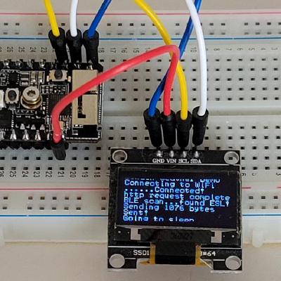
GitHub
Simple and small library to control 1-bpp OLED displays (Linux + Arduino) - bitbank2/ss_oled
has features beyond what Adafruit has in their GFX/OLED libraries
proven mauve
This is probably exactly what I'm looking for, I appreciate the help
acoustic nebula
🙂
proven mauve
we'll know in a few minutes 😄
swift widget
@odd fjord Thank you. I did see that, but thought it required two pins and external resistors like the Arduino touch library. Closer inspection suggests that's not the case. Will try it. Thanks, again!
proven mauve
@acoustic nebula this is really fast
but I get a pulsing effect on the screen, but I'm not sure if I'm using the commands right yet. If I slow it down to 1 fps it's not very noticeable, but running at 20fps you can tell its blanking out and then displaying text quickly, and with no fps limit it sorta shows letters in waves
it runs great at 3.4mhz tho, I'm getting almost 700k cycles per second with a 1fps refresh rate
acoustic nebula
what are you doing with the text?
you may want to try using a back buffer to draw into, then send it to the display after you create the image you want
single pixel scrolling is built in
proven mauve
I think I'm doing that....
let me put this somewhere so I don't blast the room with a bunch of code
acoustic nebula
if you're overwriting the same spot with new text, then you shouldn't be filling the screen between text writes since it's not needed.
that will cause flashing
proven mauve
I see
acoustic nebula
in the normal "render now" text mode, it will overwrite what's underneath it
proven mauve
so the code is two files, here's the first one: https://pastebin.com/4QXGxbNd and the second: https://pastebin.com/tSS3faME
Pastebin
Pastebin
yeah, I got rid of the fill and the flashing stopped, I'll just have to intelligently add it places when the text changes
acoustic nebula
as long as you understand what each function does, you can avoid pitfalls like that.
proven mauve
holy cow, this is fast
acoustic nebula
OLEDs have extremely fast refresh; if you leave part of the display blank for even a few milliseconds, the eye will see it
You'll figure out the right balance of back buffer operations versus direct display update
 proven mauve
yeah, thanks for pointing me towards your library. This is really cool. Just have to get over the hump of learning a new screen implementation
acoustic nebula
I tried to make it simple, but it's hard to explain how bits/bytes/pixels work to someone not used to it
proven mauve
my "with backbuffer" times were about half of yours on that video 😄
acoustic nebula
that video was run at 400Khz
proven mauve
gotcha
acoustic nebula
let me know if you have ideas for new functions that would be useful for other people too
I don't have a specific project at the moment, but people have needed various features for their projects, so I added them to my library
proven mauve
oled.print("text");
oled.println(var);
😄
acoustic nebula
I need to publish an example sketch for the sprite function
proven mauve
I've gotten really used to the 'adafruit standard' and think in it now lol
acoustic nebula
print and println will drag in a ton of code. I left them out so as to keep things compact. You can just use sprintf() to get the same features if you need that stuff.
proven mauve
I figured that's why you did it that way
acoustic nebula
my code still runs on an ATtiny85. Adafruit's never did
proven mauve
😄
acoustic nebula
I'm in the middle of modifying my color LCD library (bb_spi_lcd). I'm seriously toying with the idea of porting my GameBoy emulator to run on a Cortex-M0
I think I can make it fit in 32k of RAM
proven mauve
If you get it to do bmp's without taking up 15kb, we can work it into the standard tamaguino project to fit a lot more features into what an UNO can do. I had to move to bigger chips to pack more features in because of that.
acoustic nebula
You can use the compressed animation code (in ss_oled) to display full screen bitmaps that take up less than 1K byte each
You can also pass it a Win BMP file to display
proven mauve
the way it's currently running is it puts together around 6 or 8 bmps into a picture then displays it, to separate animations between the pet and ground/sky/mountains/etc
acoustic nebula
depending on how "messy" the bitmap is, my code usually compresses between 2 and 5:1
proven mauve

GitHub
Tamaguino Mega Version based off jakob's project @ - SandwichRising/Tamaguino-Mega
acoustic nebula
if you define them as sprites, it will probably take up less space
proven mauve
there's an example picture on there
acoustic nebula
I'm looking at the bmp files on your project...
why are they 2.3KB each?
oh - you're using 24x24x32-bpp BMP files with just black and white pixels 😦
proven mauve
lol
acoustic nebula
yes, you're wasting nearly 32x the space for each of your little bitmaps
proven mauve
lol, I'm fairly new to this. I don't know a better way to compress them yet beyond what jakob originally made
acoustic nebula
Windows supports a 1-bpp format too
the bmp files in your GitHub appear to be all 32-bpp (32 bits per pixel)
acoustic nebula
light bulb goes on 🙂
proven mauve
and it needs to only be one bit per pixel....
proven mauve
that, and the adafruit oled library itself takes up half the available space
but that will defintely help a lot
ha, thanks
acoustic nebula
glad I could help
proven mauve
that's twice today 😄
btw, your oled library is substantially faster then the LED one I was using to speed things up lol
acoustic nebula
excellent
proven mauve
at 20 frames per second I'm still getting 580k cycles per second which is good news. I should be able to do a lot with that.
Making MIDI stuff 😄
acoustic nebula
I thought my auto-detect of the I2C address was very clever, but I haven't seen anyone copy the idea yet
proven mauve
I haven't either, but I'm surprised, I saw a tutorial today on finding i2c addresses with a tiny bit of code. Seems intuitive to link them together if you're making display libraries
what does it do if you hook up two displays with different addresses?
acoustic nebula
p.s. I wrote a tool to display image info (to know a 32-bpp file from a 1-bpp file) https://github.com/bitbank2/imageinfo
GitHub
A lightweight (aka fast) tool for identifying and displaying the relevant info for image files. - bitbank2/imageinfo
proven mauve
of course you did 😄
acoustic nebula
you can connect multiple displays to the same I2C bus if they have different addresses
I wrote a library to control lots of them from a single MCU

On my mission to learn as much as possible about "IoT" and all of the accessories/sensors/displays that are popular in the market, I came ac...
proven mauve
I see, I see
If I use the ss_oled library in conjunction with Wire.h to talk to another arduino chip, I assume the wire will run at the same speed as I set in the ss_oled initialization (as long as I do it after wire.begin()) right?
acoustic nebula
yes, the last one to call wire.setClock() sets the speed. You can set it again after each library initializes
many common sensors will work beyond 400Khz, but then it depends on the length and resistance of your SDA/SCL wires
proven mauve
I'll just be using it to talk to a 328p hooked up to pots and a rotory encoder, to get data back to the trellis
and the oled, of course
especially now that my display is at 3v instead of the 5v LED, this really simplifies things and expands how much data I can show at once 😄
man, this stuff is cool. Thanks for making these libraries for the community
acoustic nebula
I'm really glad you find the code useful. After I learn something, write a library and publish it, it's gratifying to know that it helps someone else in the community.
proven mauve
Yeah, for sure. I'll make sure to ping you when I'm farther along in the project to show you
acoustic nebula
yes, I would like to see your progress
proven mauve
I leave on vacation in a week and part of that is 4 days in shenzhen to buy components 😄 Should be able to really flesh out some projects on the cheap after that
acoustic nebula
that sounds like a fun adventure
I have to be content with buying stuff from AliExpress and waiting 3-4 weeks for it to arrive
proven mauve
crazy enough, adafruit sells a book on buying electronics in shenzhen that will be really useful ha
acoustic nebula
although now I'm at the "hoarder's point" where I've got unopened packages of MCU dev boards
I'm going to do a deep dive on the ATSAM21D and modify a bootloader
proven mauve
yeah, ali and banggood was my go-to before, but I took a job in afg, so it's a lot more complicated now lol. Digikey and adafruit are pretty much the only vendors I order from any more
acoustic nebula
ah - military/contractor?
proven mauve
ya, ex-mil now contractor
acoustic nebula
hmm - I've been trying to sell my JEDMIC imaging solution to a military branch for a while 🙂
proven mauve
it's crazy how being in an environment like this really pushes people into self-betterment one wa or another. Most people hit the gym really hard, but I do microcontrollers now haha
Ugh, yeah, I don't envy you, that bidding/govt purchase process is.... not very good. lol
acoustic nebula
I have no visibility into that
It's a solution waiting for a problem (my imaging code)
it's a super fast codec for working with 1-bpp CCITT G4 images (used in the JEDMICS scanned document standard)
proven mauve
that makes it even harder if they're not actively looking for it, Im not sure even where to break in that way
acoustic nebula
it's probably not a priority for anyone

JEDMICS is the "Joint Engineering Data Management Information and Control System” is a Department of Defense (DoD) initiative for the management and control of engineering drawings and related text in a standard repository. JEDMICS has been designed as an open, client-serv...
proven mauve
yeah, was just looking at that. Talk about specialized ha
that's interesting, sounds like high level stuff. I ran an armory when I was in and did limited levels of weapon repair and I've never heard of that repository lol
acoustic nebula
In my younger days, I saw that CALS and JEDMICS compressed image standard as a fun thing to write a viewer for
I think it was because one of my customers of my Android image viewer asked to be able to view those files
proven mauve
lol, it's weird the places we end up
I wouldn't even know what a microcontroller was if I hadn't bought a 3d printer and needed an arduino to flash marlin onto it. Then I kept looking at it going, "what IS this thing?"
north stream
I used to use CCITT G3 encoding in TIFF files to make really tiny 1-bit images. It's the old RLL encoding used in faxes, optimized for typed text at a moderate resolution.
proven mauve
ha. I can't remember the last time I thought about image encoding other than bumbling my way through converting bmps to c for that tamaguino stuff
 narrow thorn
really good news for FastLED fans.. https://www.reddit.com/r/FastLED/comments/ehdxez/fastleds_bright_future/

and for those that don't know what FastLED is.. It really helps take your LEDs to the next level 🙂
 low ingot
Has anyone had a problem where the itsybitsy M0 requires you to press the reset button each time you disconnect from serial monitor?
It happens every time now on platformio, this never used to be a problem
acoustic nebula
all of my Cortex-M boards seem to behave like that
pine bramble
@acoustic nebula I needed your armasm to gnu assembler translation program the other day. ;)
acoustic nebula
nice - thanks for letting me know
pine bramble
The corporate-based toolchain is just too not Linux-y for that task.
acoustic nebula
I've probably got 2x the utilities like that (unfinished), sitting on my hard drive
pine bramble
At some point I'd like to ask you about it in more detail (not today) as I did have issues I didn't resolve.
acoustic nebula
occasionally I'll get the energy to make it into something coherent to publish on Github
pine bramble
I totally hear ya. ;)
acoustic nebula
I get so little feedback that it's hard to know where to spend my energy
pine bramble
BTW that was pretty much the only tool I saw (looking quickly) to do this.
acoustic nebula
probably - didn't seem like the Microsoft camp would help in that department
low ingot
so it's expected behavior that you can only run your program once before a hardware reset?
pine bramble
The eForth copy I have is only distributed as a (functioning!) .hex and as the corresponding (armasm - based) .S file.
low ingot
Until today it would restart the program each time you connected to the device
acoustic nebula
no, just that the bootloader/startup seems to get gummed up more often than not
pine bramble
@low ingot Don't know what you're asking.
acoustic nebula
I have a lot of old ASM code I wrote for WindowsCE. I wanted it to work on Android/iOS/Linux too
pine bramble
@acoustic nebula The general (stackexchange) consensus was that you had to port by hand between the two systems (armasm and GNU assembler).
low ingot
If I want to rerun a program on my itsybitsy m0, I have to either reprogram it or unplug it to disconnect the serial
pine bramble
@low ingot Well you need a means to restart your program without doing those things.
acoustic nebula
I saw some simple ways of converting between the 2, so I wrote brute force string search/replace utility
low ingot
I've never had this problem on any arduino or even the M0 until today
pine bramble
NVIC thing. I'll link an example.
low ingot
You should just be able to close and reopen your serial monitor to restart a program
pine bramble
Do you want the hard core (complex) version or the simplest I can find (quickly)? ;)
acoustic nebula
the serial monitor probable toggles the virtual DTR signal. This may not always do the trick depending on the USBSerial state
pine bramble
What operating system? Windows? MacOSX? Linux?
acoustic nebula
I can power up Ubuntu or Windows (bleh) if needed
low ingot
I'm on windows atm
pine bramble
Can't seem to find a complete example that's short.
Including <Arduino.h> might be enough (or not even that much, if this is a singleton .ino sketch you're working on).
void _warm(void) {
    NVIC_SystemReset();      // processor software reset
}
That'll zap some of the internal states but won't for example turn off an RGB LED that has its own 'supervisor' chip inside itself.
acoustic nebula
sorry, wasn't sure if you were talking to me or SMetcalfPS
pine bramble
I call that a 'warm reset' but I don't really know exactly what it will or won't do.
It should be enough to run the program again, as if you'd unplugged the Trinket M0 and then plugged it back in, for most use cases.
It doesn't quite do what pressing RESET does, as that involves the bootloader code (which NVIC_SystemReset() probably does not call).
I think .. not sure on that either. ;)
Dan would know right off the top of his head. ;)
A lot of times you simply need to escape the endless loop.
Make your own endless loop in setup() rather than the official Arduino loop() (which will never be reached, if you do this right).
If you do all that you won't lose valuable system state information as an NVIC reset would.
(You might want to preserve things unrelated to program control)
low ingot
the NVIC seems to cause the port to become unreadable.
pine bramble
Maybe this'd go easier if you showed your entire source code (all of it. ;)
USB is pretty complex and I've been there, where the USB oriented stuff wasn't re-entrant.
(In those cases I didn't solve it really very satisfactorily, but I was in Atmel Start and the USB oriented code was primitive).
The reason I asked about the operating system, was that not all comm programs (putty maybe, in the case of Windows) are equal.
Some release the port easily; some hang onto it.
(or something like that)
I like microcom in Linux for just this reason.
It releases the CDC ACM kernel-supervised use of the serial port.
(USB serial)
 bold saddle
I just did a board update for Adafruit SAMD boards and now I cannot compile any script for a Metro M4 board. I get the following error message
"Arduino: 1.8.10 (Windows 10), Board: "Adafruit Metro M4 (SAMD51), Enabled, 120 MHz (standard), Small (-Os) (standard), 50 MHz (standard), Arduino, Off"
exec: "/bin/arm-none-eabi-g++": file does not exist
Error compiling for board Adafruit Metro M4 (SAMD51).
This report would have more information with
"Show verbose output during compilation"
option enabled in File -> Preferences."
north stream
Did you also update the Arduino SAMD package?
pine bramble
bold saddle
I tried completely uninstalling and reinstalling the Arduino IDE and updating all boards and libraries. No luck. It still won't compile even blink.ino
bold saddle
If I rollback Adafruit SAMD Boards to version 1.5.7 it compiles just fine but if I used the latest 1.5.8 version it refuses to compile with the error message I posted above.
It now looks like version 1.5.8 is no longer available. They must have pulled it because of the problem.
 heady python
is there any information on what the maximum resistance that the itsybitsy M4 ADC can deal with? I know for the atmega arduinos it's generally 10kΩ
 lost nest
@heady python Some math required, but it's worth the read: See Table 54-24 and Figure 54-5
of the datasheet: http://ww1.microchip.com/downloads/en/DeviceDoc/60001507E.pdf
pine bramble
https://termbin.com/nhki
I think one of the Makefiles may've propagated a path error for the compiler.
Haven't quite looked into it. ;)
 burnt island
does anyone know where the Arduino sketch to go with the thermal camera mode of the BlueFruit app is hiding?
heady python
@lost nest awesome, that answers all of my questions, thanks!
pine bramble
STM32 Cores got an update recently. 1.7.0 > 1.8.0
pine bramble
it's in there
proven mauve
so... I notice something about using .h and .cpp.... In my main sketch I use a currentMillis global variable to control the timing of everything instead of delays. And, if I #include .h files to break the program up into modules, I can use the currentMillis global variable in the functions I wrote in the header file. But if I #include a .cpp file in the header file, the global variable currentMillis is out of scope for it and can't be used ...
So, I default to just using .h's because they work the way I am wanting the separate files to, but I notice I'm the only person doing this... because it's not proper to just fill them full of code instead of breaking them into a .h and .cpp with the actual coding in the .cpp... and it makes me feel dumb lol
maybe I just need to start passing values more
surreal pawn
so... it sounds like you don't understand how c++ compilation works and how variables (global or otherwise) are hooked up
it's frustrating that you have to know this for c++ but here's roughly how it works: #include just copies code into the current file, it doesn't matter the file extensnion. Next, every variable (and function and type) needs to be declared in the current assemblage of files after pre-processing (also called a "compilation unit").
if a variable is declared, say long currentMillis; at the global scope, the compilation unit will include additional global memory for this "global" variable. If instead it were declared as extern long currentMillis; the compilation unit will not allocate memory for that global variable, but it will be found in some other compilation unit at the linking step
so putting global variable declarations (without extern) in your .h file is typically a bad idea because it means you get duplicates of these global variables