#help-with-arduino
1 messages · Page 44 of 1
 pine bramble
pine bramble
pine bramble
#include "common.h"
I authored 'common.h' myself so that's how I've included it in my sketch.
Notice there are no angle braces around it, just the quotes
 rough torrent
so this works:
sketch_nov06c
#include "foo.h"

// add_foo();

void setup() {
  // put your setup code here, to run once:

}

void loop() {
  // put your main code here, to run repeatedly:

}
foo.h:
int foo = 0;

void add_foo(){
  foo ++;
}
Yeah.
Kinda sounds like when you include a library, it pops.
Since it's an otherwise empty sketch, that points to a library that is not matched to something pretty basic in the overall system.
Like an outdated lib that has one too few or one too many parameters passed to a function in it.
rough torrent
So should I try to update all the libraries again?
Or should I install what the pictures show at https://learn.adafruit.com/adafruit-pygamer/arduino-libraries ?

Adafruit Learning System
Fits in your pocket, is fully Open Source, and can run CircuitPython, MakeCode Arcade or Arduino games you write yourself!
So like if the picture shows installing version 1.5 and the latest version is 1.7, should i install 1.5 or reinstall 1.7?
pine bramble
Try the latest version always, and back off only when you have to.
Just about everyone you interact with assumes you're keeping up to date on lib versions.
Pygamer is so new that it only makes sense to keep up with the updates, as how old could they be, anyway.
rough torrent
Not that old, unless they release an update every month
pine bramble
For the PyGamer, treat it as BETA.
Assume every update really matters.
It's a new product line.
rough torrent
Ok 👌
So after I finish testing every library I think I installed with the PyGamer, i'll reinstall the libraries, and try uploading the example code again
pine bramble
Just do the include files (the .h files) first.
If that compiles, great.
If it doesn't, it may not mean anything (it's a weird idea but I'm looking for shortcuts ;)
rough torrent
This is the library compile list that works or not
pine bramble
Your downloads are really difficult to manage.
Some other method would be better. My system treats them as closed captions.
(I have no idea why)
Maybe a gist on github.
rough torrent
textuploader.com - Library Compile List of Success or Fail
WORK:
#include
#include
#include
That should be better
rough torrent
Well, when I press Sketch -> Include Library, and the library, I just compile whatever header file includes pop up.
pine bramble
So were there errors?
rough torrent
Well, for the DON'T WORK section, they just say error compiling
pine bramble
Yeah I could see how a menu-driven experience could cause that many include files to be .. included.
thanks, I missed that!
There's enough that do work to make this puzzling.
rough torrent
Now should I just reinstall the latest version and probably reboot my computer in the process?
of the libraries
pine bramble
What's the operating system?
rough torrent
Windows 10
pine bramble
In general, you exit the Arduino IDE, then start it, having made sure it's really no longer running before you do so.
 thorny sequoia
when writing C code how would I distinguish between an feather M0 Adalogger from a feather M0 Proto?
pine bramble
Steve they might be the same.
<.arduino15/packages/adafruit/hardware/samd/1.5.7/boards.txt>
rough torrent
Maybe you could put a file on the feather M0 Adalogger like type.txt with the contents of Feather M0 Adalogger
And on the Feather M0 Proto you coul put type.txt and put Feather M0 Proto
Then parse that file
pine bramble
Both are probably Feather M0 not Feather M0 Express
I don't thinkthe compiler can tell them apart.
thorny sequoia
Hmmm so is there anyway to distinguish between them when using pin 4 for my sdcardpin on the M0 adalogger and pin 10 for my sdcardpin on the M0 Proto?
Ckyiu - How would one put a file on the device? I haven't done that before?
pine bramble
adafruit_feather_m0.build.extra_flags=-DARDUINO_SAMD_ZERO -DARM_MATH_CM0PLUS -DADAFRUIT_FEATHER_M0 -D__SAMD21G18A__ {build.usb_flags}
adafruit_feather_m0_express.build.extra_flags=-DARDUINO_SAMD_ZERO -DARDUINO_SAMD_FEATHER_M0 -DARM_MATH_CM0PLUS -DADAFRUIT_FEATHER_M0_EXPRESS -D__SAMD21G18A__ {build.usb_flags}
Those are the only two Feather M0's the compiler knows about.
thorny sequoia
Where does this go?
pine bramble
LadyAda could have made two boards using the same microcontroller chip, but with different pins utilized. If that were the case, you'd need to distinguish between them.
It's already there; what I just showed is already installed.
It's part of the board support package.
boards.txt
It's not part of a program that you write; it's present for the overall system to work with.
boards.txt is updated every time Adafruit puts out a new board in the same category (SAMD).
thorny sequoia
How do I reference the boards.txt? Sounds like a plan,
pine bramble
In linux it's under ~/.arduino15 and other systems place it elsewhere.
Basically you want to look at 'variants' but when you find boards.txt you're quite close to where the variants code is stored.
(I always use boards.txt so that I can compile code conditionally for several different boards)
It gives all the flags you can test for -DADAFRUIIT_THIS_AND_THAT
thorny sequoia
Okay. Thanks for all that. I now have a starting point. I'll go and see what I can find. Thanks for the help!!
pine bramble
-DSAMD21G18A
-DADAFRUIT_FEATHER_M0_EXPRESS
Just drop the -D part.
#ifdef SAMD21G18A
   do_this();
#else
  do_that();
#endif
Oh okay. Got it!!!
pine bramble
The above program will only call one of those two functions.
In this case, it'll do so for any SAMD21 (G18A variant) microcontroller in the catalog (in boards.txt)
So for example it will not succeed (it will do the #else part) for SAMD21E18A (notice the E)
thorny sequoia
Just awesome - thank you.
pine bramble
You're very welcome.
thorny sequoia
When I switched one of my projects from an M0 Adalogger to an M0 Proto (Express) it seemed like there was a conflict on pin 6 (Oled Reset) so when I executed " if (!SD.begin(SDCARDPIN) " the Oled went blank. I fixed the problem by not using pin 6. Is there a known reason for this?
I should mention when I had a mistake in my wiring on a breadboard and had the oled reset plugged into pin 9 (even with the wrong reference ) and it worked. When I designed my PCB with the correct pin is when I found the oled went blank, but fortunately I had the wrong pin wired on the breadboard which worked, so I knew how to override my PCB.
The forums mentioned many conflicts between oled and data loggers but not this particular one. Any thoughts?
pine bramble
thorny sequoia
Okay. I'll do a read through and see what I can find. Thanks.
pine bramble
x
.arduino15/packages/adafruit/hardware/samd/1.5.7/variants/feather_m0/variant.cpp
.arduino15/packages/adafruit/hardware/samd/1.5.7/variants/feather_m0_express/variant.cpp
pine bramble
When I still don't understand it in the Arduino IDE, I look at the CircuitPython source for further insights, as the development team is very current with CircuitPython versus the target boards that Adafruit sells.
Adalogger has D4 on PA08 but the other doesn't seem to have this.
That's also mapped to SD_CS.
So in CircuitPython, the same pin can be referred to (perhaps in different contexts) as either D4 or as SD_CS.
variant.cpp is ordered exactly in D0, D1, D2 .. Dn sequence.
If they're not labeled with a comment in variant.cpp you can just count to get to the correct D number for the pin.
Whereas pins.c seems to be organized more in banks of related pins (like all the analog pins, for example).
The earlier downloads pages I linked carry the schematic diagrams for the target boards.
The schematics are very accurate.
I don't know if they are amazingly accurate, objectively, but to me, they are! :)
thorny sequoia
Oh wow! This makes sense! I've used the schematics a little bit, but now I see why I should look at them more. I also need to start looking at the circuit python source moving forward. I hadn't thought of that as this is an older project that I'm revamping so I haven't started using the circuit python yet, but for all my next projects I plan to use it. But now that you pointed this out I'll take a look at the circuitpython source from now on. Thank you again for your help.!!!.
pine bramble
You're welcome. I tend to use the documentation they already provided; and that often boils down to the code and the schematic. Tony DiCola pointed out that the schematic is always right, so I listened and yup, they are.
thorny sequoia
I've used the documentation to get started and to solve when things don't work if I can find it, but I typically go to the forums first. You've opened my eyes to another great source, the schematics. Thank you.
pine bramble
Yeah I'm a hardware person so I grew up on reading schematics.
the Air Force rather insisted on it. ;)
thorny sequoia
Funny. My background is software. I actually never touched any hardware.
I always had to figure out cryptic error codes written by software people who had no clue how to write an error message.
pine bramble
Hehe. If they were trying hard.
Yeah, the schematics we had contained elements such as DS1 for a light bulb.
I asked why DS and the instructor said darkness sucker. ;)
thorny sequoia
Okay, it's not just the software people.
pine bramble
Those were incandescent bulbs.
thorny sequoia
HaHa - that funny, really funny - lol!
pine bramble
LED wristwatches came out around that time; we already had 7-segment LED calculators.
Personal computers, not quite yet.
thorny sequoia
I started writing code on punch cards and then tape.
pine bramble
oof. hollerith.
I've never seen it done.
We did have punched tape readers and punchers, here and there.
thorny sequoia
Same, old IBMs and then PDP8 and 11s for me.
Then timesharing
Before relational DBs..
pine bramble
They had a machine in the test bay -- a 2U unit in the rack. Beatiful front panel to it.
Had 8 toggle switches you used to key in a single keystroke.
thorny sequoia
Yea - i unfortunately remember
pine bramble
That's how you bootstrapped the punched tape reader.
I want to build one of those.
They used fanfold mylar punched tape. 5 hole code.
thorny sequoia
when I was a college student I worked at a hospital that had developed an inventory system in FORTRAN. I had to use the bootstrap tape to bring up the system so I could work on it. Of all languages FORTRAN???
pine bramble
I want to say baudot but I don't really remember anymore.
pine bramble
The only under someone's thumb type stuff I had to do like that, was deal with consumer oriented software for IBM PC clones, when I worked for a (Mitac?) personal computer retailer.
And all that unpaid consulting for friends and family.
Once they got the word I only run Linux now, they backed off. ;)
thorny sequoia
I tried to stay away from that as much as I could
pine bramble
We used to say "I'm a walking F1 key" to that.
thorny sequoia
lol - your too funny
 north kelp
The first computer I used was the DEC PDP 8/E, and we loaded from and saved to punched paper tape.
pine bramble
Yeah, five years earlier and I would have had a crack at those. ;) We had a dial up time share at 180 bps or 300 bps acoustically coupled modem - just the teletype on our end.
thorny sequoia
I remember and the disk drive (64 meg) was aluminum and like 1.5 ft wide
all basic code
pine bramble
A friend of mine worked on 'core' memory. Hard to describe it.
north kelp
Similar here – dialed up from junior high via 110 baud modem on Teletype Model 33.
Teletype Model 33 ASR
Core memory!
thorny sequoia
in high school that's what we had!!! and the yellow tape - all ascii in basic
Memories!!!!!
pine bramble

 undone oracle
@north stream ugh, i mixed up for loop with if statement eariler 🙄 sorry about that
pine bramble

Magnetic-core memory was the predominant form of random-access computer memory for 20 years between about 1955 and 1975. Such memory is often just called core memory, or, informally, core.
Core memory uses toroids (rings) of a hard magnetic material (usually a semi-hard ferri...
I've never seen it so I cannot imagine the tedium of .. servicing it.
north kelp
I appreciate core memory, paper tape, and punch cards now, because they gave me a visual, tactile experience of bits missing in modern computing.
pine bramble
I hear that.
thorny sequoia
Exactly.
pine bramble
So, we didn't get to clean the horse stables, as our parents 'already' had automobiles. ;)
north kelp
Given the resurgence in vinyl (outselling CDs now) and film photography, perhaps there's room for a hipster paper tape/punch card product from Adafruit.
thorny sequoia
Ebay it!
north kelp
I hear the data is more mellow on paper/cards. 😉
There's a pretty good match between the size of MCU programs and those I wrote back in the day for Altair, DEC, etc.
thorny sequoia
I remember writing a graphics program on the Altair - that goes way back
north kelp

Adafruit Industries - Makers, hackers, artists, designers and engineers!
A Minimal Punched Tape Reader The rig is composed of a Teensy++ 2.0, eighteen red LEDs, eighteen resistors, and a few bits of laser-cut plastic. LEDs are used to both illuminate the paper and sense…
thorny sequoia
I have my old tapes - I can findout how good my coding was - haha
north kelp
What computer(s) were those tapes for, @thorny sequoia ?
Are there modern emulators you could load your tapes into?
 paper nimbus
anyone happen to know why the arduino delay function is written in this more complicated way:
void delay(uint32_t ms)
{
uint32_t start = micros();
if (ms > 0) {
    while (1) {
        while ((micros() - start) >= 1000) {
            ms--;
            if (ms == 0) return;
            start += 1000;
        }
        yield();
    }
}
}
as oppose to something simpler like:
while (micros() < start + ms*1000)
yield() ;
thorny sequoia
We were timesharing and writing BASIC through a teletype. It was all ASCII.
This was highschool.
1975
north kelp
@paper nimbus That's weird.
I'd look at the Arduino source on GitHub, and the history of that code, and what issues it's connected to.
thorny sequoia
Really interesting - the compiler was most likely not capable of the latter
Most old compilers could only handle code that was for 8-bit s or maybe at best 16. Needed many steps then
 paper ledge
@north stream You've got to be kidding me. Rubber duck debugging. That has to be the funniest thing i've read all week!
I have been programming for quite some time and sadly I have never ran across anyone who has ever spoken of such but that is by far one of the funniest and yet oddly helpful things I've ever read. Thanks for sharing 🙂
pine bramble
Those don't depend on any platform (Windows, Mac, Linux).
Plus you can link to individual line numbers when discussing them.
north kelp
@paper nimbus The only thing I can think of is that the current approach ensures that, while microsecond timing is used to make delay() more accurate, yield() only has to be called every 1 millisecond, vs your elegant version. In yours, I think yield() would be called every microsecond.
pine bramble
So if someone wanted to know which flags the compiler uses that are specific to the pygamer, I'd just link this way:
https://github.com/adafruit/ArduinoCore-samd/blob/master/boards.txt#L1019
north kelp
@paper ledge I think we all do rubber ducking, but don't necessarily have a name for it. I myself only learned the term a couple years ago.
@paper nimbus This seems to be the first commit that moved from using millis() to micros() internally to implement delay():
https://github.com/arduino/ArduinoCore-avr/commit/67c0a1995aace2953e481ef6183b1b91e04942fc
 paper ledge
@north kelp Right, I tend to bounce things around for hours before the answer tends to magically float into my field of view. I can honestly say i'm glad I wasn't drinking anything otherwise I would have probably be cleaning a huge mess lol.
north kelp
I think the cool part of the technique of rubber ducking is vocalizing and telling a story about what you're doing to an inanimate object, which both creates an opportunity for insight, and makes us appear even weirder to onlookers/coworkers.
pine bramble
@thorny sequoia All that comes together in compatibility.h in a project I have. The purpose is to make porting from one target to another easier, by disabling/enabling features specific to a target board (such as which pin the onboard NeoPixel is on).
pine bramble
Well it started out that way. ;)
Now it's a mess and I don't understand it myself. ;)
There's better syntax but you have to study the cpp to get to it.
 north stream
I did add 32 bits of core memory to an Arduino.
pine bramble
wow. holy mackerel
north stream
That was after I tried building a 1-bit core memory out of a random ferrite toroid I had lying around. Even though it's (probably) a "soft" ferrite, instead of the "hard" ones that are good for core, it worked!
pine bramble
That's also hysteresis I think.
north stream
Assembling that shield was tricky, those cores are tiny
north stream
No, Jussi Kilpelainen created the kit, I just assembled it. https://www.tindie.com/products/kilpelaj/core-memory-shield-for-arduino/

Tindie
A retro 32-bit memory for Arduino using ferrite cores.
There's this project that uses Neopixels to visualize it https://hackaday.io/project/163976-interactive-core-memory-shield-using-led-matrix

This project started as an exploration of "what if..." and that lead to the creation this proof-of-concept when I bought one of Jussi Kilpelainen's 32-bit Core Memory Shields for an Arduino. I found a NeoPixel Featherwing was a pretty close fit with the 4x8 core array, and 3D...
 proven mauve
So... I have some ssd1306 oled screens, and most of them are I2C. However the sketch runs too slowly when using the I2C ones vs the SPI ones, even is I set Wire.setClock(400000L);. Thought I'm using the adafruit gfx library, but I assume that Wire.setClock still works... even thought I don't actually notice the sketch running faster when I set it to 400000. But if I unplug the screen the sketch runs at normal speed (I can tell by the speed of the sounds coming out of the speaker). Is there anything I can do to make I2C not bog down the sketch?... Like maybe disable the verification it does on the data it sends, or anything like that? Will putting my bmp hex getting displayed in SRAM instead of in PROGMEM help?
The sketch runs so fast using an SPI display that I have to put a framerate limit on it using millis()....
pine bramble
I figured out my trouble with Serial1 on ItsyBitsy M4: apparently the "char" type is unsigned by default! This goes against every C standard I know (maybe I don't know so much..?). Can anyone confirm that this the case, and that it is by design or a bug? This is with Arduino 1.8.10 on Win10.
proven mauve
weird, char should be a value from -128 to 127. Byte should be the automatically unsigned version.
pine bramble
Indeed. I can specify "signed char" but a simple char should be signed by default.
pine bramble
Apparently it's not defined and ARM compilers usually make it unsigned... First time I depended on it being signed, I guess ¯_(ツ)_/¯
proven mauve
I don't see any difference in setting different Wire.setClock(); speeds at all when using the adafruit ssd1306 and adafruit gfx libraries with this program. The display.display(); is definitely causing the slowdown, and I've got the code down to only using one of them...
 dull bison
Is this the place to post code that doesn't work?
I have this piece of code in my loop(), but it stops after the "yes we have connection". I can't figure out why he doesnt print the net lines
if(Serial.available() > 0){ // Checks whether data is comming from the serial port
received = Serial.read(); // Reads the data from the serial port
Serial.println("YES WE HAVE CONNECTION");
Serial.println("=======================");
Serial.println(" ");
Serial.print("received = ");
Serial.println(received);
Serial.println("=======================");
}
proven mauve
My issue has to do with the using the newest adafruit 1306 library. If I change versions it runs at full speed. GOing to work on it more later and if I come up with anything I'll... talk more about it...
 rocky igloo
@proven mauve Have you looked through Adafruit_SSD1306.cpp? I see a BEGIN_TRANSACTION macro which calls a SETWIRECLOCK macro which calls wire->setClock(wireClk). And wireClk will always be 400000 unless you include a different value to use in your call to the Adafruit_SSD1306() initializer. "Use the source, Luke."
proven mauve
I haven't gotten that far into it yet, I was all over the place trying different things to get rid of the slowdown. So, it's always running at 400kHz, which is good, unless the initializer specifies otherwise.
I'm eventually going to need to go through the whole thing and figure out why version 1.1.2 runs at full speed and why the latest version has so much slowdown, but I don't think it will be today now that I have a work around
Thanks for pointing that out to me, I appreciate it @rocky igloo
proven mauve
Okay... so I have a 3.7v lipo battery connected to a charging board which is also a 5v boost board, and the charging/boost board is connected to the arduino. The charging board accepts usb to charge, and works well, but when the usb is unplugged it drops power output for around 300ms, long enough to reset the arduino....
Now... I'm thinking... maybe I can use a transistor and a diode to switch to a direct connection with the battery when the charging board cuts off, and then turn off the power supply directly from the battery when the charging board cuts back in... Am I thinking straight?
north stream
I'd just connect it so the boost board is aways running. Failing that, I don't think you need a transistor, just a diode or two.
proven mauve
the boost board is also the charging board, so I'm kinda limited
and when the charging board switches off wall power is when it cuts out
north stream
That does make it trickier.
proven mauve
I might be able to run it all off 3v, I'll test in the morning. But, it looks like the program was running at speed, the display was just a little dimmer
thanks for the input though, I really do appreciate it
pine bramble
@dull bison Split out everything inside the conditional to a separate function, and see what changes.
I didn't see an error.
also, join the Arduino discord (@_adafruit linked it the other day).
It's in a pinned message in this very chan.
The #coding-help chan there is a good place to ask further.
@proven mauve is it designed for (essentially) uninterrupted power?
A real UPS has a big battery, and a circuit that decides to failover rapidly, good enough that a 120VAC connected PSU doesn't hiccup and cause a host (desktop) PC to reset.
A laptop similarly fails over to the internal battery, also very reliably engineered to do so.
You might be able to tandem-power the input to the boost so that it always has power.
Especially on the bench when you're not in portable operation (walking around with the gadget in your backpack).
Not really following how/when/where the supply power gets cut to the target board.
This is worth a quick block diagram. ;)
proven mauve
so yeah.... it's an Atmega running a virtual pet, essentially. It will need charged daily. But when you unplug the charger right now, you lose power long enough to reset the device completely
so you start it up and you run around all day, power is fine. you get home and plug it in, power is fine. You unplug the charger when the battery is topped up, the board quits sending power to the Atmega while it switches over from wall power to battery and the Atmega resets
pine bramble
So you have a wall wart supplying N volts, supplying a boost converter thing from Adafruit?
proven mauve
close, I do have adafruit's one but not for this application. The booster/charger in question is this: https://www.amazon.com/gp/aw/d/B07D3SQYKJ?psc=1&ref=ppx_pop_mob_b_asin_title
pine bramble
There's a connected battery somewhere. The target board does not have two power inputs, one for a battery, and one for a USB power source, is that right?
proven mauve
exactly. micro USB charges it, standard USB powers the device, soldered leads connect to battery
pine bramble
Well my thinking is this: Adafruit uses two connectors; one is for LiPo and another is for +5VDC.
The board has a supervisor chip that handles the fail-over.
Crickit goes even further.
proven mauve
Which makes sense. You get what you pay for 😁
pine bramble
I did manage to use two power sources with just a diode for protection in a project, but one of the sources was just an electrolytic holding up the supply to a PCF clock chip (PCF8523 or something; don't remember the exact part number).
What's the max current draw at the point of failure in the circuit?
(when the failure event is apt to happen)
The AVR is probably good for 10-40 mA. Wild guess there.
proven mauve
plus a small oled screen, one of the .96" ones
pine bramble
OLED has no backlight, is that right? You could blank the screen before switching power.
Capacitors add in parallel (resistors add in series) iirc.
proven mauve
correct, the oled pixels are self-lit. But, these are for dummies and I was trying to avoid a manual process when unplugging the charger, otherwise I'd do an eeprom save/recall so it was all just software
pine bramble
You could build up a larger reserve with more electrolytics in parallel, I'd think.
So you want it so that someone can trip over the power cord in the dark. :)
proven mauve
I have some 330 uf and some 470 uf's or so, so I think I'd have to chain all of them together haha
pine bramble
Ask bodger but I think those add in parallel (in this case, increasing the time you have before the sag in voltage event becomes critical).
The BFC that Adafruit had in the catalog might be worth trying, too.
proven mauve
I think I have some charging boards that don't drop out, but they also don't boost. Experimenting tonight it looked like the program was running at speed under 3+v, so I might try that tomorrow. Would be worth it just for the battery lifespan of that's the case
oh wow, that's a monster! lol
So the whole project is destined for an Altoids tin lol
pine bramble
Wow that is a big one. I gotta get me one of them.
Wonder how long a standard low-load sketch would run on that.
Maybe 0.25 seconds. ;)
proven mauve
lmao
I gotta get some sleep, I'm over in the sandbox so it's about that time. Thank you for the help, I always appreciate it! I'll take another swing at it in the morning, I've almost got all my hardware issues solved and I can focus on software
My Atmega 1284's got here last night with some ARMs and some 480-somethings to play with
So I'm out of the 32kb constraint without changing much, which helps a lot, when I found it the program was already at capacity lol
pine bramble
Hehe I used to work with 8kb flash and 768 bytes RAM limits with C8051F330D ;)
Taking a break is always good. Lets your brain take in what you've learned.
north stream
I used to work with a maxed-out 6800 evaluation board with 512B of ROM (6830) and 768B of RAM (6 x 6810), so I get that.
 cyan jasper
I have a problem with arduino/AVR sleeping. Basically I send a stream of messages over Uart and do some more calculations send it off to sleep but it stops at same character every time. Could it be because it goes to sleep before finishing sending data?
 mild elk
Post your code please
proven mauve
oiy... so I have my arduino hooked up to the 3v charing board now... and.... it doesn't draw enough power to kick in the board's power supply lol
but if I hook it up to an uno it'll power it
I wonder how bad it would be to have both the battery and atmega hooked up to the battery connections on the charging board....
north stream
Might work, might confuse the charging circuit.
pine bramble
/random I'm getting good results bringing up the Arduino IDE from scratch, by using 'Adafruit' as the first search term in the Library Manager box.
Seems to be an efficient means to locate needed libs (especially when I'm just reproducing a previous ~/Arduino/libraries directory (in Linux) (so I know all the names).
The directory names for each lib are working out to be valid search terms.
The 'fuzzy matching' Arduino IDE uses just obstructs what I want. ;)
The Audio lib is a Paul Stoffregen-ism and is less simple to identify. I vaguely remember installing it. pjrc.com and Teensy branded stuff.
Arduino/libraries/Audio/examples/Tutorial/Part_1_02_Hardware_Test/Part_1_02_Hardware_Test.ino
is present in this lib. Easy means to check what you have, with such a generic name.
 burnt island
@cyan jasper Could be. Adding a Serial.flush() before you go to sleep should wait for that to be sent
 surreal pawn
@pine bramble adafruit has a fork of the teensy audio library. https://github.com/adafruit/Audio

GitHub
Teensy Audio Library. Contribute to adafruit/Audio development by creating an account on GitHub.
pine bramble
@surreal pawn Thanks! That's very likely what I had installed. ;)
examples/HardwareTesting/TrellisTalkthrough/TrellisTalkthrough.ino
is not present except in Adafruit's version, and is what I had, previously.
mild elk
I'm fetching a rather large json with ESP8266 but it rarely gives me a complete file and often looses a lot of data on the way. Why is that?
north stream
I'm guessing either the data gets split up into packets and the parsing begins before all the data has arrived and been put in order, or running out of memory.
mild elk
There is no parsing for now, it gets the file and prints over serial
Out of 7 tries I got the whole file only 2 times
Alright, seems like the fix was really simple - just add a little delay before printing it to serial
mild elk
So now I have a string data incoming, and I'd like to get only some certain pieces from it. How do I do that?
north stream
There are lots of ways to slice it (pun intended). I usually decimate data as far upstream as practical so I don't eat bandwidth sending data that's going to be discarded anyway. My usual approach is some sort of state machine (possibly implemented with Flex) that keeps track of the data stream as it's going by and toggles between the "pass on" and "discard" modes.
mild elk
I found that my json is too big to fit in a heap and it doesn't parse properly with ArduinoJson library
north stream
You may need to identify sections with simple-to-code schemes like the seventh and thirteenth instances of the "geometer" element five levels deep. Then your code can keep track of { and } symbols, incrementing and decrementing the level counter for each, and when it finds a "geometer" element at that level (bounded by quotes), count it, and if it's one of the locations you're interested in, pass it on.
That sort of code is a little annoying to write (which is why Flex is handy), but even a small processor is capable of doing it.
mild elk
Annnd my code doesn't fetch it properly anymore
Great
This is so annoying
I think I'm gonna drop that project
cyan jasper
@burnt island thank you man very much appreciated
pine bramble
mild elk
Thanks! I'll have a look into that
pine bramble
I read the Grand Central M4 documentation, specifically https://learn.adafruit.com/adafruit-grand-central/pinouts and https://learn.adafruit.com/adafruit-grand-central/adapting-sketches-to-m0 but I can't find info on what classes I should use for the second, third etc serial ports. "Serial" = SerialUSB = the serial port on the micro usb connector. "Serial1" = pin 0=RX/1=TX. But do the other RX/TX pairs simply follow on Serial2, Serial3 etc? It's confusing that Serial1 refers to RX/TX, but pins 10/18 are called RX1/TX1 and are presumably addressed by Serial2?
What is also, not really confusing maybe, but annoying to have to keep in mind, is that RX2/TX2 and RX3/TX3 are on consecutive pins but reversed to what is the norm: RX first then TX.
Oh, I see on https://www.arduino.cc/reference/en/language/functions/communication/serial/ that on the Mega the Serial1, Serial2, Serial3 pin combos are reversed as well, and that Serial1 uses pins 19/18, NOT 10/18 like what is stated on the Adafruit documentation page for the Grand Central. So I assume that should be 19/18 as well. (Edit: d'oh, it says "#10 / RX1 - GPIO #19" the second part of which I apparently glanced over. Still inconsistent & in need of a little fix, of course.)
Too many (great) products, Adafruit, and not enough structure to the documentation...
pine bramble
hey, im currently trying to use the PN532 RFID NFC sheild
but getting some weird stuff on serial monitor
any idea what ive got wrong?
proven mauve
does that happen when you wave the rfid tag near it?
pine bramble
When i wave the mifare card over it yeah
pine bramble
@mild elk All that interrupt handling is kind of unproven. Regard it as 'superstitious' programming (no real connection between reason and action haha).
Still. It seems to work, somewhat.
I think the morse tones improved with added interrupt handling (to prevent rotary encoder interrupts while the tones are sounding on the piezo buzzer element).
 wind drift
I am trying to connect my Adafruit nRF52840 Feather Express with BLE to my phone. I tried the Bluefruit 52Blueart example but I am getting the error: Disconnected, reason = 0x28
Or am I missing some important setting?
wind drift
I also updated my bootloader to the latest version but I still get the error
 stable forge
@wind drift if you have an Apple device to try, that would be an interesting comparison
wind drift
@stable forge yes I used an iphone 6S but get errors: "Disconnected, reason = 0x3E" & "Disconnected, reason = 0x8"
But I also just tried another board (same model) which seems to work
so maybe it's a bootloader or hardware issue?
Because I am using the exact same arduino sketch
stable forge
does the other board also work on Android?
wind drift
Yes works on android
stable forge
Are these Feather or Circuit Playground boards?
wind drift
Adafruit nRF52840 Feather Express
stable forge
could you check the BOOT_OUT.TXT contents for both boards when you double-click to get the bootloader?
wind drift
Will check 1 sec
Ah I think boot_out.txt is not there when I use arduino ide, or is ist?
stable forge
sorry , not BOOT_OUT.TX, I mean the other text file. BOOT_OUT.TXT is for CIRCUITPY
wind drift
Not using circuit python atm
stable forge
INFO_UF2.TXT
wind drift
I suee INFO_UF2
Working one:
UF2 Bootloader 0.2.9 lib/nrfx (v1.1.0-1-g096e770) lib/tinyusb (legacy-755-g55874813) s140 6.1.1
Model: Adafruit Feather nRF52840 Express
Board-ID: NRF52-Bluefruit-v0
Bootloader: s140 6.1.1
Date: Feb 22 2019
Not working:
UF2 Bootloader 0.2.13 lib/nrfx (v1.1.0-1-g096e770) lib/tinyusb (legacy-755-g55874813) s140 6.1.1
Model: Adafruit Feather nRF52840 Express
Board-ID: nRF52840-Feather-revD
Date: Sep 25 2019
however it had the same 0.2.9. bootloader earlier but was also not working at the time which is why I thought updating the bootloader might help...
stable forge
hmm, on the bad board, do you see it listed to connect to, as with the first board?
did the bad board ever work?
wind drift
Yes it's on the list
It never connected - BLE connection never worked (but other functionality does)
stable forge
is it soldered up to anything?
wind drift
Nope - just plugged into a breadboard (but no wire connected)
stable forge
if you look at the components on the good and bad board, do you see any difference: something missing, etc? If it's easy for you to take a side-by-side clear photo, that might help
wind drift
Looks the same to me
right one is the bad one
Okay hold on - now it's half-ish working all of a sudden
I put the program on again
Then tried to connect and it was stuck at connecting for a good 20 sec (other one is instant)
'22:02:54.773 -> Connected to '
It does not display a device name (the other one does)
north stream
A clue!
stable forge
the tiny metal box near pin 11 (not the smaller component), does it have a number stamped on it? (can't see that on the photo)
that is the crystal; i just want to make sure it's not upside down
wind drift
yes I think 00205
stable forge
I suspect the hw may just be bad; when did you buy this?
wind drift
Uhm ordered around end august and delivered around mid september
I now tried a couple of times to disconnect & reconnect and sometimes it works (after 20 sec delay) and sometimes I still get 0x28 error
stable forge
have you tried any CircuitPython BLE on the bad one
stable forge
also you could try a scanning app and see what the received signal strength is for both boards; "nRF Connect" is free and will give the signal strength. But that would just diagnose a hw problem maybe.
If it does not work well with CPy, start a thread in https://forums.adafruit.com and say you've had trouble and briefly describe the difficulty. I'll verify it's hw and authorize a replacement. Ping me when you post because I read the forums irregularly.
stable forge
np - I've seen some hw issues on the board but with the SPI flash, not with Bluetooth radio stuff
 hallow oxide
I'm looking to create a project that uses a ESP32 and a display. Maybe a ILI9341 TFT.
What does the screen refresh rate look like? Would I be able to display a gauge, and have it be extremely reactive to the micocontroller's sensors?
 rugged steppe
@sour tide
I'm working on a project, but I don't have an idea on how to use a feather board to make a GET request.
I've looked it up, but can't find anything.
I'm trying to get data from a air quality api
 sour tide
@rugged steppe are you using arduino? I wouldn't know either
rugged steppe
Feather huzzah
north stream
There's an example on the Huzzah learn page https://learn.adafruit.com/adafruit-feather-huzzah-esp8266/using-arduino-ide just scroll down to "Connecting via WiFi"
 river osprey
I have a trinket M0 and i'm trying to drive a 128x128 TFT SPI display... I have the wiring correct, because it displays the "adafruit" logo, but the uncanny eye sketch then crashes trying to draw the eye... Any thoughts? (video posting shortly)
pine bramble
The only thing that comes to mind is storage - Trinket M0 has no SPI flashROM chip.
river osprey
Oh ok - so it's possible I have to use something like an itsy bitsy then?
pine bramble
I have no idea, but I'm guessing the project you're following could be data intensive.
The fact that the logo displays says most everything is working as it should, I'd think.
In particular, the Trinket M0's MCU is about as capable as the others are (Feather M0 Express for example).
river osprey
well - if it has not SPI flashRom and would likely need it, then it'll save me TONS of time to just use a slightly more expensive chip
$5 more of a chip is worth 4 hours of me banging my head on this hahaha
pine bramble
They actually go out and buy a second chip and add that chip to the board to get the SPI flashROM. ;)
What guide are you working from? Link it here if you can.
river osprey
well - i'm building something that I hope to resell (in reasonable quantity) so if i can use an $8 Trinket as opposed to a $13 Itsy Bitsy - i try to
but, if that's what i have to work with, thats OK
Ultimately i'm using the uncanny eyes: https://learn.adafruit.com/animated-electronic-eyes-using-teensy-3-1/software

Adafruit Learning System
Ride the express bus to the Uncanny Valley
at least - that's my test sketch
river osprey
I've used the same sketch on the hallowing (an m0) and the itsy bitsy m0 without any issues
this is just my first attempt using it on a Trinket m0
north stream
It would be interesting to figure out what it's doing when it crashes, but it is reasonable that the Trinket just doesn't have enough resources to run it.
river osprey
that goes beyond my knowledge but if someone can give me tips on debugging or something to try, i'm happy to do so
north stream
I think the Trinket uses the E18 version of the chip and the Itsy uses the G18, but I'm not sure what (other than pinout) is different between the two.
It does have some chatty print statements, so you can follow along in the serial monitor to see what it's doing.
river osprey
let me see if i get anything in the console...
sadly nothing in the console..
i guess my next stop is to just try it with the itsy bitsy and if that works chalk it up to the trinket not being able to handle it 😦
north stream
That may be the most efficient. Debugging the Trinket may be an interesting science project, but may well not bear fruit.
rugged steppe
@north stream thanks!
stable forge
@pine bramble @river osprey The eyes sketches don't use SPI flash, so there's some other issue
pine bramble
Thanks! @stable forge
Linking the sketch would help, as there are huge animations that lock up my web browser, trying to find the correct one. ;)
stable forge
pine bramble
@river osprey The sketch looks like it would be easier to do on CPX.
river osprey
Thank you @stable forge do you think it could be hardware or software? Any thoughts?
pine bramble
You might need to specify which eye (left or right).
river osprey
Bus, cpx is overkill. Plus I know it works on a itsy bitsy which is half the price of a cpx
Also, small is better as I want to embed it in the cover of a book. Similar to the monster manual project
pine bramble
So how do you know it doesn't work as is, again?
stable forge
@river osprey I am text chatting with the author at the moment. WIll be back.
river osprey
Great, thank you Dan.
stable forge
are you using an identical display to the Hallowing display (in terms of the display chip, ST7735?)
river osprey
Let me look up the specs
stable forge
the eyes code is only written to work on a particular OLED display and the ST7735.
the SAMD E18 and G18 chips are really similar; it's mostly just how many pins and peripherals are available. It may even the same actual chip with different stuff turned on/off
river osprey

www.banggood.com
Online Shopping at Banggood.com!
ST7735s
the smallest one (1.44 inch)
pine bramble
Did you get a blinking eye using this same TFT (on any M0 target board)?
river osprey
Nis - i have not yet tried to get this working with an Itsy Bitsy, which is likely my next choice, as I know that works with the Adafruit breakout board
stable forge
are you checking the code for pin differences, etc.?
river osprey
Dan - yes, i know the pins are correct as it displays the adafruit logo (which is sent from code)
i have a video above if you scroll up a tad
stable forge
we do overclock the SPI peripheral. Do you know where it's crashing
river osprey
pine bramble
@stable forge The primary .ino file looks for several SERCOMs.
https://github.com/adafruit/Uncanny_Eyes/blob/master/uncannyEyes/uncannyEyes.ino#L265
river osprey
I attempted to set it to 12000000 for the SPI rate as well and that didn't work...
stable forge
do you have one of our ST7735 displays? I'd try it on that first before the Banggood one.
Their "ST7735" may not be exactly that
or it may be a lower-spec part in some way
river osprey
Dan, I do happen to have one, so that's a good call- i can try that as well
how do i read the SERCOMs?
stable forge
yes, try that first, and try to isolate where it goes wrong with some print statements (or wire up a J-Link)
try with a Feather M0 or CPX, then go down to the Trinket
pine bramble
river osprey
thanks for the suggestions, I'll have to give it a try tonight - i'm at work and can't to doo much testing...
stable forge
sure, good luck! If you get settings that work for other boards, PR's for the code would be welcome!
river osprey
nis - i'm not sure how to read that, but is it possible that I need to disable the SERCOM as it seems i can't use SPI + sercom?
pine bramble
This could be the problem:
https://github.com/adafruit/ArduinoCore-samd/blob/master/variants/trinket_m0/variant.h#L123
Can't SPI and i2c in a single project / trinket m0
(the eyes have code to sync left and right eyes via i2c)
stable forge
but i think this is one eye?
pine bramble
I'm guessing the code didn't autoselect correctly.
river osprey
danh - yes, i have it only setting 1 eye, but if it's initializing the sercom couldn't it possibly have conflict?
pine bramble
The code is explicit for CPX which was the only reason I suggested trying one if you had one onhand.
stable forge
if SYNCPIN is not defined or is ==0, it shouldn't be using I2C at all
river osprey
eyeInfo_t eyeInfo[] = {
#ifdef ADAFRUIT_HALLOWING
// { 39, -1, 2 }, // SINGLE EYE display-select and wink pins, rotate 180
{ 0, -1, 0 }, // RIGHT EYE display-select and wink pins, no rotation
#else
// { 9, 0, 0 }, // LEFT EYE display-select and wink pins, no rotation
{ 0, -1, 0 }, // RIGHT EYE display-select and wink pins, no rotation
#endif
};
thats my definition - just one eye...
pine bramble
You can add a cpp directive #warning to trace what's really being defined or compiled.
stable forge
i have to go for a bit, but will hear back from you later. bye!
river osprey
thank you
river osprey
i am getting a serial.println now - 22 - which is the FPS
pine bramble
They play the same role as Serial.println("Warning Will Robinson"): debug statements do in an Arduino.ino style program.
river osprey
so it's not crashing - just not sending data
pine bramble
Might be sending it elsewhere. ;)
river osprey
or that too - again with the sercom possible issue
the confusing part is that the logo sends, so it's getting data correctly to start, then not...
pine bramble
You could gut the code some to remove confusing side-issues but that can be time-consuming.
I like that logo business. That validates your wiring, and says that at some point the program used the correct SERCOM.
river osprey
that's what i'm doing now - trying to comment some things out
pine bramble
I haven't looked at it deep enough to understand how the logo got sent.
But I did one on an LCD (and even modified the logo).
since the logo is (probably) multi line that also means some ordering of the screen painting geometry was also correct.
river osprey
it uses ->drawBitmap()
eye[0].display->drawRGBBitmap(
(eye[e].display->width() - COLOR_LOGO_WIDTH ) / 2,
(eye[e].display->height() - COLOR_LOGO_HEIGHT) / 2,
color_logo, COLOR_LOGO_WIDTH, COLOR_LOGO_HEIGHT);
pine bramble
Sometimes with GFX you need a show thing to actually paint.
EDIT: found no evidence that this would have been relevant. ;)
Put in a `Serial.println("foo") near LINE 107 in the .ino
That should say what happens with i2c
eye[e].display make a backup and change every e to a zero, in this construct.
river osprey
i tried a few things, nothing helpful. for now i'll have to wait until after work when i can test with an adafruit breakout board and possibly a different microcontroller
pine bramble
That e there is for the second eye. ;) It uses a hard-coded zero there in one case.
river osprey
actually - that just gave me an idea...
i had a comma at the end of my eye definition
which would make arduino think there was a 2nd eye
even though it wasn't defined
which probably messes everything up
<--- has trouble keeping languages straight as i use too many of them
Well crap - didn't help
oh well - unless someone has another idea, for now, i'll have to wait
thanks to everyone for their suggestions
pine bramble
I think SPI uses a chip select line and that may be relevant to the 2nd eye.
So you could be on the correct SERCOM but enabling the wrong chip select line. Or something similar, electrical.
I would guess that in such a case you could code around that.
Looks to me like MOSI MISO SCK are allocated, which means a GPIO pin for chip select for the second eye, if my intuition isn't off on this. ;)
IF the select line is electrically tied to GND that part of the code shouldn't impact it.
 karmic stream
does anyone know, how to check, whether my code segment is currently being executed from within an ISR()?
atmega328p
like pending bit stuff, I'd guess? maybe someone knows this right off the bat.
pine bramble
@karmic stream My idea (untested) is to increment a counter in the ISR, to get a sense of how often it is called. A simple counter made in the language, not on the hardware level.
I think debuggers are used for this but I don't know.
There's the possibility of toggling a GPIO port pin, in real time, and watching on an oscilloscope.
karmic stream
...
discord kills my messages.
That hacky stuff is not exactly what I'm looking for, as I'm still doing a hardware abstraction layer of interrupts, I need performance and it is expected to be executed in a context like this ```
if(InterruptVectorTable::instance().inISR())
ToggleBlueLED();
else
ToggleRedLED();
What else would call your ISR?
pine bramble
You can use a piezo buzzer to annunciate the toggling of a port pin, and scale the clock frequency to make the buzzer actuate in the audio (human hearing) range.
59 cents vs $250 for an oscilloscope ;)
pine bramble
In general, I'd say that Arduino 'culture' isn't all that aware of ISR's.
I only know a very limited set of ways to adjust the clock frequency, and it's quite technical programming to do it (for SAMD21).
There are language elements in the Arduino IDE to handle interrrupts.
pine bramble
Topic: Arduino ZERO timer interrupts:
http://forum.arduino.cc/index.php?topic=332275.17
surreal pawn
GitHub
happy wrappers for TC modules 3,4,5 on SAMD21. Contribute to adafruit/Adafruit_ZeroTimer development by creating an account on GitHub.
you pretty much have to read the datasheet and platform code to get it right though
here's another example: https://github.com/adafruit/Adafruit_ZeroTimer/blob/master/examples/timers_callback/timers_callback.ino
GitHub
happy wrappers for TC modules 3,4,5 on SAMD21. Contribute to adafruit/Adafruit_ZeroTimer development by creating an account on GitHub.
 heady sparrow
@river osprey Check your wink & blink pin settings. If either or both are set to one of the TFT control lines (CS, DC, etc) then it's possible the eye will be stuck in a permanently-closed position. Wink & blink should probably both be -1, I don't think there's enough IO on the Trinket for both the display and inputs.
(I have no idea if the eye code will actually work on Trinket. In THEORY it's possible, there's enough RAM & flash, but I don't recall if there's any differences with regard to DMA peripherals and such.)
river osprey
Thank you paint. I am going to try with an adafruit display tonight and you with the code. I will post results if anything positive is found
karmic stream
It's about abstracting features of multiple controllers. I do not call it myself, but provide the functionality if multiple boards/board families provide it. It's not about how or why or when am I going to call it, it's about whether the feature exists and whether to add it to the abstraction if all controllers support it in some way.
As sadly everyone seems to be used to using the arduino framework etc, it seems to not make any sense to ask here, as it would be easier so read through the manual. I asked in the hope that somone might have done something similar and knew the answer right off their mind, guess not. Thanks for your time.
I'm not using the arduino framework, I'm baremetal on the atmega328p-pu, which is basically the same microcontroller that's being used in the arduino uno.
 median mica
I would like to use the Trinket M0 as a keyboard with an IPad. I’ve got it working. I’d like to remove the usb connector to save space. Can the data lines from the usb be connected to the rx and tx pins? Is this a stupid question? It’s serial data right?
river osprey
@heady sparrow @pine bramble @stable forge Update on the trinket + display, it also fails with the adafruit TFT breakout, but I realized that the adafruit has SO,SI and SCK, yet the SO is not connected (and not present on the other display). Is that an issue? It also displays the logo but nothing further
So - I'm going to assume that it's code for now, and possibly a pin conflict and will spend some time diving in to see what/where
As the code has not crashed - it's consistently telling me I have ~22FPS (the occasional 23)
heady sparrow
Should be OK leaving SO connected.
So the splash screen stays on the displays? Or does it go blank after that?
stable forge
@median mica The TX and RX pins are for a UART; they cannot be remapped to USB without rebuilding CircuitPython. But you could just remove the USB jack and solder to the data line pads.
river osprey
The splash screen displays and then stays (with adafruit display) with the other, it tries to render something garbagy then goes either blank or all white
Ummm crazy question @heady sparrow will the randomSeed(analogRead(A3)); affect things since that's mapped to another pin?
or will that just take a reading then release the pin?
ignore - that's before any initialization of other pins
heady sparrow
Should be fine.
river osprey
Also - THANK YOU
THANK YOU THANK YOU THANK YOU
Your code has been amazing, and I've used it in tons of projects i've made. I've even sold Mad-eye moody eyes that run a slightly modified version of your code. You truly are amazing and an inspiration
ok - that said, back to debugging 🙂
 verbal mason
Anyone know how I can have a random number generator exclude previously generated numbers from a range? Like if it already picked 7 it wouldn't be able to pick it again
river osprey
just store your numbers in an array and check against that, i don't believe there is anything built in like that
OR, if you want an evenly-distributed random number generator, then generate your values (1-20 for example) then randomly sort the array
and pop values off
I think the issue is port confusion - i'm using SDA to pin 4 which is labeled MOSI whereas 0 is SDA... let me try to do some pin swapping and see if that fixes things...
https://cdn-learn.adafruit.com/assets/assets/000/049/778/original/adafruit_products_Adafruit_Trinket_M0.png?1514756138 the trinket has a port labeled MOSI and one labeled SDA... which should I connect to the DN/MOSI/SDA pin on the display? https://cuneyt.aliustaoglu.biz/en/content/images/2018/10/colour-tft-screen.jpg


what i had was 0->CS, 2->RST, 1->DC/A0, 4->SDA, 3SCK, but i think 4/0 should be swapped
stable forge
@river osprey did you see the text here: https://learn.adafruit.com/adafruit-trinket-m0-circuitpython-arduino/pinouts#unique-pad-capabilities-3-4
I haven't checked it against what you said yet
4-MOSI, 3-SCK,
river osprey
what i'm a tad confused about is - with the display, it says "DN, MOSI, SDA" but SDA is pin 0, and MOSI 4...
so i'm not sure which to use...
MOSI or SDA...
stable forge
SDA is an I2C term, I'll lok at the schematic for the display
river osprey
to be fair, the display itself just has "SDA" printed on the back
stable forge
yes, looks ok. D2/A1 is part of the SPI SERCOM, so you can't steal it for CS. But can't you just tie CS permanently high (or is it low?)
does the display require toggling CS?
you're not sharing the SPI bus with any other device
whats the product number for the display?
river osprey
it's not adafruit
stable forge
oh, I thought that one was not workign right and the adafruit one was ok
what wiring are you using for the adafruit display, and which display is it?
river osprey
i attempted the adafruit one
and it didn't work as well
at least not with the same wire mapping
sorry - it likely would have been smarter for me to get the adafruit one working first ahah
ok - i have pin 0 and 1 open and RST and DC
which should i map where and test?
0 says it's use for SDA i2c data - so should i use that for DC?
stable forge
The SPI sercom is going to claim 4 for MOSI, 3 for SCK, and 2 for MISO.
you're not using I2C at all. You're just using 0 and 1 as GPIO pins, so it doesn't matter which for which. The "SDA" marking on the display doesn't correspond with the SDA on the Trinket.
river osprey
ok thanks
stable forge
but I'm confused; this says ILI9341 and I thought you were using a banggood ST7735 display
river osprey
that is not the exact device - just had the same pinout
i'm using: With PCB backplane
Resolution: 128*128
Driver: ST7735
Only 4 IO drivers are required
stable forge
point to the exact device again
river osprey
www.banggood.com
Online Shopping at Banggood.com!
the 1.44 size
i'm attempting the new pinouts with the adafruit display
stable forge
the documentation link is broken there
river osprey

This lovely little display breakout is the best way to add a small, colorful and bright display to any project. Since the display uses 4-wire SPI to communicate and has its own ...
for the adafruit TFT - what is the select pin - SCK?
// This table contains ONE LINE PER EYE. The table MUST be present with
// this name and contain ONE OR MORE lines. Each line contains THREE items:
// a pin number for the corresponding TFT/OLED display's SELECT line, a pin
// pin number for that eye's "wink" button (or -1 if not used), and a screen
// rotation value (0-3) for that eye.
i just want to make sure i'm pointing to the right pin with the eye
so would select be the D/C or SCK?
stable forge
that is an st7753r board; st7735 and st7735r are different; let me do a little more research
well 🤷 that's the board suggested in the Teensy Uncanny Eyes guide, so, oh well
river osprey
which board the 1.44 adafruit breakout?
stable forge
yes
river osprey
if i can figure out the pinout, then i think that's the issue
i just feel like i'm 1 pin short
stable forge
TFT_CS is the "select" pin
you need a D/C pin and a RST pin too
(not the trinket "RST" pin, of course)
river osprey
ok - so since 3/4 are dedicated to SPI, then i have 0,1, 2 for DC, Select, and RST
stable forge
but 2 is reserved for MISO, except maybe you can say you don't need it. I'm not familiar with the Arduino SPI library, hold on...
river osprey
2 is MISO
stable forge
oops, yes, my typo, sorry, fixed
river osprey
Now i'm not getting anything. I believe what I've learned is that trinket will just not be the right board for this project
stable forge
do you have a different M0 board to try?
river osprey
it could just be a wiring issue, and it's likely solvable but too much effort
quite a few - i have an itsy bitsy m0 that I know works with the adafruit display and likely i'll get it working with the other display tomorrow
but for now, it's late
Thank you so much @stable forge for your amazing help and being here - it means so much
stable forge
sure, it's just that the Arduino support for SPI is confusing. np.
river osprey
That it is - and I'm new to quite a bit of this, so it's very touch and go
stable forge
looks like reset pin could be optional
river osprey
lets give it a try!
stable forge
unfortuantely I don't have one of these displays to try
river osprey
displays logo, but no eye... using the following pins:
0-> TCS, 1 -> DC, 2->MISO, 3-> SCK, 4-> MOSI
3v/gnd appropriate
code is running - as it's displaying a FPS
could it be that without a RST it's never clearing the screen?
ok - i think i'm just going to use the itsy bitsy - hopefully i can get this going soon, but too much effort
stable forge
maybe; one thing I read is that you could perhaps reassign MISO to use as something else if you grabbed it after setting up the SPI.
but yes, get it working and then try experiments later
river osprey
i've spent 4 hours trying to save a 1/4 inch and $5
stable forge
but I thought you were mass-producing these
river osprey
not exactly a time/cost savings hahaha - but i have learned alot!
well - yes, but likely only in the 10s of quantity
but yes, i'd like to get it working down the road
for now, i have 1 order that has to be fulfilled
stable forge
well, i will order of the 128x128 in my next order and fiddle a bit with it; i should have one around for testing anyway
river osprey
For my mad-eye moody eye, which currently uses the adafruit 1.44 TFT ($15 and often out-of-stock) switching to the 1.44 TFT which has a smaller footprint and is only $6 was certainly tempting
and - with the itsy-bitsy it might work perfectly. the added bonus of using the trinket vs itsy-bitsy would have cut total price by $15
stable forge
i can understand; easiest is a Hallowing, but that has lots of extras that push the price up for you (like accelerometer, flash, etc.)
river osprey
my first version was a hallowing - but it's also bulky, meaning the case had to be bigger
stable forge
good night and good luck!
river osprey
thanks!
rocky igloo
@river osprey @stable forge On those boards, the MISO and MOSI pins are connected the SD card socket, not the display. The pin that's labeled SDA is the display's MOSI, SCL is the display's SPI clock, and no MISO of course.
river osprey
thanks tim!
rocky igloo
On the one I have, there are five signal pins toward the middle that I used: CS, SCL, SDA, A0, and RESET.
river osprey
Update - got it working on the Itsy Bitsy... but, after about 4-5 seconds it goes blank...
but it's now WAAAY past my bedtime
thank you again everyone for your help
rocky igloo
@river osprey Are you powering both LED+ and VCC? On my board, I had to power both pins. It faded out after a few seconds if VCC wasn't powered. (Maybe you'll see this in the morning. Nighty-night.)
river osprey
I have both vcc and led wired to 3v. I tried changing vcc to 5v but that made it die quicker
Well. To USB. But I will be running this from a lipo
rocky igloo
OK, probably not it. You might have some ideas for things to try tomorrow if you sleep on it.
river osprey
I can try to ensure the pin is connected right. I am in bed now so I will check tomorrow
Let’s hope. Thank you for the info
pine bramble
https://learn.adafruit.com/using-atsamd21-sercom-to-add-more-spi-i2c-serial-ports/creating-a-new-spi

Adafruit Learning System
Get more high speed serial commports without bitbanging
quote Say you only want to transmit SPI data, you can leave out the pinPeripheral(12, PIO_SERCOM) line, and you can keep using #12 however you like
(scavenge the MISO pad for GPIO use)
 lost notch
I have a question. I have two modules in one arduino. One is SIM800 GSM and one is HC05 Bluetooth and each of them have different baudrates.. Now is it possible for me to use both of the modules setting up each of their own baud rates in one Arduino Uno? I appreciate any help!
median mica
@stable forge thanks for the information. Adafruit is awesome!
north stream
@lost notch You have a few choices. The most obvious one is to use SoftSerial to talk to one of the devices (probably the slower one). Another is to have steering logic and share the UART, but that's a lot of work. There are also a few Uno variants that use the -B version of the chip that offers a second hardware serial port
 full root
Greetings. Several questions regarding managing a filesystem on QSPI flash using the Arcada library on my PyBadge. Am I in the right space?
 eager jewel
@river osprey, I tried hooking up a display to a Trinket M0 and was unable to get that working successfully either using hardware or software SPI. I'm not sure if there's some kind of trick to getting the display working with the Trinket as it's not a board I've used much.
stable forge
@river osprey note that @eager jewel is our resident display expert.
eager jewel
I think the issue has more to do with the Trinket than the display since it is shown to be working with an itsy bitsy.
river osprey
@eager jewel Thank you - that's super helpful. I have both the cheaper and the adafruit display working with my itsy bitsy m0 but for some reason they both die after about 3-5 seconds (see the video i posted last night)
i'm about to start with a fresh set of source code assuming i broke something harsh in all my debugging
eager jewel
Can you try out graphicstest?
river osprey
but i really appreciate you trying and saving me tons of time trying to get it working on the tinket
The raw, original (modified only for pins) uncannyEye sketch works now for Adafruit TFT breakout - testing for the other display
eager jewel
Ok, cool
river osprey
Working perfectly with the cheapy display as well - I've said it before, and I'm sure I'll say it again - I truly appreciate everyone's support - these things are frustrating enough to go through alone
eager jewel
Great to hear!
river osprey
now to document these pinouts...
north stream
And we appreciate people documenting things like this once they've figured them out!
river osprey
Well - i would feel awkward making a learn guide - since it uses a competitor part...
but I certainly can note that trinket m0 can't run a display 🙂
eager jewel
Well, I would need to dig deeper with the Trinket such as hooking up a logic analyzer, but mine is all packed up for Hackaday SuperCon.
full root
In the forums, discussions are kept separate, so joining a chat where they're all mingled feels odd. But here goes. I'm moving my sketch to PyBadge using Arcada to manage small files. Question 1 is this. I'd like both my sketch and my USB connected computer (Win7) to have read/write access. The issue is that the computer can't see new files written by the sketch. Forced refresh doesn't help. Only a disconnect or reset makes the changes appear. Is this normal behavior? Thanks.
surreal pawn
yes that's normal
you aren't going to be able to read/write the sd card from both windows and a sketch
 vague kettle
programming is hard lol. time for a break
full root
@surreal pawn It sounds like the same would be true in the case of QSPI flash on a PyBadge, yes?
rough torrent
yes @full root
here it says that both can't do it at the same time: https://learn.adafruit.com/circuitpython-essentials/circuitpython-storage
yes it's circuitpython but the underlying file system still has the same rules
north kelp
@full root Instead, maybe you could have the PC talk to your PyBadge over Serial, and code on the PyBadge would read/write the files for you.
full root
@north kelp I suppose so, but my hope is to keep all things simple for my fellow beginners. I'll work with it as is. Thanks, all. That was fast. Question 2 next.
vague kettle
im overthinking this and getting my brain all twisted. somebody wanna sanity check this for me/talk some sense into me?
im making a space station pointer, and i know im going overkill with the hardware, but i want to use what i have... im using a raspi to get info from the internet and do the heavy math, then sending data over serial/usb to an arduino, which drives the motors
full root
Question 2: My old sketch stored nearly 2000 files in a single directory using a microSD and the SDfat library. Doing the same with Arcada and QSPI flash stops before I reach 512. That's not even half full. Is there a hard limit on file count per directory? The CP-storage page didn't say. Thanks again.
full root
@rough torrent They were 1K.
rough torrent
in total or per file?
thats big
and your original question said you were using QSPI flash
vague kettle
i also have a 2x16 char display connected to the arduino. my plan for each serial 'packet' is 16char (top line), 16char (bottom line), int (servo position), unsigned int (steps to take +/-), wait for a 1 byte ack then repeat
full root
@rough torrent Each was 1K, not even half a meg total, and yes, QSPI flash.
vague kettle
is it bad form to cast the unsigned int as an int to transmit it, then cast it back? or should i send it over as a char string and convert it with atoi() or sumn?
derp, signed int, cast it as unsigned for transmission, then cast it back
doesnt seem like the serial library knows what a signed int is, its just a byte
rough torrent
@full root does it stop when the code access the files or when moving it from the computer to the QSPI over USB?
so like copying your files to the PyBadge?
or does Arcada fail to list them all and all the files are in the QSPI?
vague kettle
wow i botched that explanation
full root
@rough torrent My test sketch was set to write 512 files to its QSPI flash. 490-odd files were written perfectly, the rest never appeared.
full root
@rough torrent No microSD on my PyBadge, but an external microSD using SDfat on a Feather M0 wrote nearly 2000 similar files. The QSPI files went into the root directory, where a couple of other files and folders already lived, a total of 506 non-hidden entries. I'll have to finish this chat later, sorry. Thanks again.
pine bramble
If people don't post their code, I don't feel especially empowered to answer them. ;)
reads code and schematics
rough torrent
In this code, why does while(playing) { ... } on line 77 does not execute while the .wav file is playing?
https://textuploader.com/1odxs
north kelp
@rough torrent Perhaps your code is stuck in the do { } while() loop starting at line 70, and doesn't reach line 77?
vague kettle
rather than mucking with typecasting, i think the easiest answer is to just send it as a char array
16chars for the top line, 16chars for the bottom line, int for servo position, null-terminated string for steps +/-, and ill just convert it with atoi()
north kelp
@vague kettle That sounds like a good plan. I'm not afraid to write “inefficient” code at first to get things working.
vague kettle
yup
the other kinda easy option is to send it the desired stepper position instead, and let the arduino work out how many steps to take +/- to get there... but even then, it would be more than 1 byte, so i'd have to play with that either way
north kelp
Early optimization is often unnecessary, and a time sink that can slow my progress, and drain my motivation.
vague kettle
would still prolly be easiest to send the number as a char string
yea i got frustrated and look like a 2month break on this project lol. finally getting back into it
north kelp
I'd think about getting motors making noise and moving stuff, getting LEDs blinking, etc. That's a nice positive reinforcement when it happens.
vague kettle
got all the other bits and pieces working nicely, but hit a roadblock getting the pi and arduino to talk. got frustrated and quit for a while
i have them talking now, so thats a positive step
north kelp
Sweet! How are they talking?
vague kettle
its a pi1B, and arduino deumillanove, so both are pretty old hardware lol. i have them talking via serial/usb
5v arduino and 3v3 pi, so im using usb for comms so i dont have to muck with a level converter
north kelp
As you've probably seen me write here before, I love using Serial and a USB cable to talk between Pi and Arduino.
vague kettle
also, serial is still not working in my pi code. i have it working via terminal/minicom, so i know the comms works. just havent gotten it down in my pi code yet
north kelp
What language is your Pi side in?
vague kettle
c++
north kelp
Oooh.
vague kettle
using MS visual studio on my laptop to write the c++ program on the pi
north kelp
I tend to use Node.js for the Pi. On the Arduino side, I'll read a sensor, and send JSON to the Pi.
vague kettle
im making a space station pointer (any satellite really), and all the other parts of the project work. just need to get comms down, and plug the parts together
need 4 bits of info. accurate current time, accurate GPS location. compass direction, 2lines of satellite info that updates every 2weeks or so.
i dont have a gps or compass yet, so those are hardcoded. the pi has a good NTP client for accurate time, and im able to pull the 2line satellite info from a website just fine
north kelp
Nice!
vague kettle
im using the SGP4 orbital mechanics library, which i dont really understand the math, but the results match what google says, so it seems to be working
north kelp
What GPS options are you considering?
vague kettle
havent even looked yet. but since the project will live mostly indoors, its prolly gunna be a powered gps, which means big + power hungry
also, with the stepper motor and servo, im not sure about using a compass lol
ive heard gps compasses arent very good, until you start moving/driving
but for now, i just hardcoded my gps location, and i point it north before powerup
biggest problem so far: raspi sucks at driving motors, and the orbital math cant fit on the arduino. the library is bigger than the arduino can fit, and even if it would fit, it would be slow
north kelp
Since it's indoors, GPS location will be pretty static, right?
vague kettle
yup. but if i take it to a makerfair or sumn, i dont wanna have to modify the code
perhaps i could drop that info a file on the pi's SD card, but meh, ill worry about that later
north kelp
Or you could run a small web server on it, and send GPS location from your phone.
vague kettle
also, i want to display 8 lines of data, but i only have a 2x16 display lol. so im gunna show 2lines for 5seconds, then show the next 2 lines
it already needs to connect to local wifi, so it can get time + satellite info. sure i only need to update that once per day, and it could be a webserver the rest of the day
AND i want those 2 lines to update in real time. for example, show a clock, and see the clock ticking
north kelp
Is the goal to point the direction of the satellite using the motors?
vague kettle
so ill send the [16char, 16char, servo, stepper] packet, wait for an ack, then do it again. hopefully its fast enuf to get a decent refresh rate. then every 5 seconds the pi will send the next 2 lines of data, and update them as fast as possible
yup. wanna see?
north kelp
Sure!
vague kettle

no servo action in that vid, but thats my 'robot'
copied the structure from another youtube video, its not my idea. but im doing the code myself. not cheating by looking at his
north kelp
Nice hardware! Did you fabricate the metal parts? Or order them (from where)?
vague kettle
the parts are called 'actobotics', and they are like an erector set / legos for robot nerds
you can get them from sparkfun, servocity, etc etc
north kelp
Oh yeah. I've seen those at Sparkfun a while back.
pine bramble
That turntable should be able to carry a decent load. :)
vague kettle
they also have cad files for them, so you can prototype in fusion 360 n stuff
pine bramble
What's the visual going to be for the gnomon? (sky-object-pointer)
vague kettle
just a stick
pine bramble
Well that'll keep it lightweight.
 pine bramble
Turntable's a bit overbuilt for for that job. I would be torturing myself to make full use of that advantage.
vague kettle
the stepper is only 200steps, and i wanted more accuracy, since the math gives me 000.000 - 359.999
thats a 3:1 gear reduction, so now i at least have 600 steps of resolution
pine bramble
Now what level of study is this for? Is there going to be a grade given for this project? I'm just curious. Maybe nosey. ;)
vague kettle
close enuf for the nekked eye. not telescope level of accuracy, but close enuf for me
no grade, im an old. just for fun + to learn
pine bramble
Haha yeah I'm an old ROFL yeah me too. I'm an old.
vague kettle
😉
pine bramble
Well that explains the intelligence behind this, adequately. I was just curious.
pine bramble
(I've had a similar project in mind for a few years, but mostly for natural objects)
vague kettle
i want to add planets next, but thats a completely diff orbital model. ive found a C library that can do both satellites and planets, but i dont wanna rework that much of the program yet
pine bramble
Nope you're at the nerve center. That's Tom Kelso's site, which was active as a dial-up BBS back in the day, and has been open continuously since then.
north kelp
I'd be tempted to put a laser pointer on the end of the stick, and then turn on the disco fogger.
vague kettle
nis, that was my understanding... that this was the place to be
pine bramble
@north kelp Haha.
@vague kettle If you got a Pi and an Internet connection, you have a lot of computational power available.
I have .. STSPLUS running here .. ran it earlier in the year.
I seem to recall it generates satellite passes for you, and maybe spits them out to a .TXT file.
(would not work for natural objects)
JPL Horizons is the place to get planetary tables generated. Just store them for the dates you are on display at a trade show.
vague kettle
i want my pi to calculate the passes itself. even if i dont understand the math in the SGP library, its there for me to read + start to dig into
pine bramble
Well that's what STSPLUS does. ;) Lots of other programs do, too.
vague kettle
i still need occasional TLE info tho. iirc it upudates approx every 2weeks... (when the SGP model falls inaccurate by a certain % then NORAD updates the TLE, which celestrak then makes public)
pine bramble
Linux has a decent supply of satellite programs that work with TLE's for artificial orbital craft (or any human-launched vehicle in space).
Kelso's probably still pulling them from NORAD.
vague kettle
the webpage reads that way
pine bramble
He was 'Major Thom. Kelso' at one time; don't know if he still goes by that.
vague kettle
lol
pine bramble
I assumed he was USAF.
vague kettle
going downstairs for a cig. if you take off, its been very good to talk to you sir 🙂
ill be back in like 8-10
pine bramble
I hear ya. Good idea. ;)
vague kettle
back
cleared my head, suppose i shouldnt even worry about how to send a negative number over serial.
lets just get it working at all from my code
i made 2 programs on the arduino to help me debug/get it working. first says hello world then starts counting up from 0, once per second.
2nd one says hello world, then waits for an input. then responds with what it saw.
they both work great from minicom on the pi. now to get em working from a c program on the pi...
pine bramble
reading but can't type atm
I had the coffee, too, so a good one-two punch, there. ;)
vague kettle
just thinking out loud lol. do your thing 🙂
pine bramble
Well so you want C program to play the role of minicom, is that right?
vague kettle
thats where im at, yes. i want serial comms to work from my c/c++ program.
ive been toying with wiringPi and wiringSerial, but cross compiling like this is a pain, and im pretty sure i dont have it set up correctly yet
libraries arent in the correct spot, so the c linker cant find em, and i get compile errors
pine bramble
What computer languages do you know that are already on the Pi? C, I take it. Anything else?
(I've never compiled C on the Pi .. not once. ;)
(should have; can't be very difficult to get ./a.out going there ;)
vague kettle
i took c and asm classes back in college. im pretty good with an oscilloscope too. not great with any modern langs
i did the free 'codeacademy.com' class in python, and it was fun. but im a long way from being able to use it
pine bramble
We used gforth to talk via serial port all the time. Should be available on the Pi (for me) (you may not want that particular rabbit hole)
gforth played the role of an intelligent minicom, basically. Use it in an xterm.
'expect' is also a good choice for simple conversations with a serial target board such as Arduino, from the PI.
(we used it to autologin to a BBS via modem)
(then get out of the way and behave like a minicom, iirc)
vague kettle
ive found some more 'natural c' things i can copy paste, but they are more complex than i wanna dig into. it looks like arduino made some easy to use libraries for the pi, and im having trouble making them work
dependancy problems
pine bramble
links?
(I have Pi hardware here, unpowered but connected and ready to boot into ;)
I've totally forgotten how to use two computers at the same time, if possible, on the same display, so I tend to memorize what I saw with my eyes on either side, and then type into the other one what I've learned ;)
My display is an HDTV with multiple inputs (including a DB15 for VGA). The Pi gets one of the HDMI inputs. This (my main) computer gets the VGA port connection to the same display. I do have picture-in-picture on a much smaller display I rarely use.
(DVI-D and VGA, I think, can run concurrently, but I don't remember)
My idea: a six inch plastic dome, with the gnomon connected to the sky pointer, inside that dome. Both on servomotors (cheap hobby aircraft ones).
I just want it to point to the three usual sky objects when I ask it to, and tell me which one it's pointed to (as feedback, having asked for that one).
Saturn is up right now in the southwest.
xephem - saturn - now - northeast USA
(must compile - no distributed binary)
All those I normally use for planets and stars - observationals.
I don't routinely use anything non-local to this machine for TLE visualization.
This looks like a candidate:
http://www.orbitalpredictor.com/about/
https://www.amsat.org/track/index.php
pass predictions
vague kettle
sry, family got home. chatted with them for a bit
post the code? ew no lol. its very much just prototyping parts together. very ugly
i mean maybe, but i dont want to lol
using this library:
Dan Warner.
pine bramble
Anytime you take out time from this for the real world is a good time. No worries. ;)
Oh post all code. Many of us post ugly code. At least, I do.
If it compiles and runs, it ain't so ugly.
Once in a while a program I wrote (or more likely, just modified) looks pretty good right at the start. But only once in a while. ;)
(and only at the start! haha)
vague kettle
lol fine
ok so see this page: program 2: sattrack
Dan Warner.
thats the info i have. i want to put time/date up for 5 secs, then Az/El for 5secs, then Rg/RgRt for 5secs, then Lat/Long for 5 secs


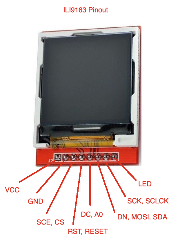
ooo i swore? sorry
in that code, i get 1 part to work, then comment it out. then get another part to work, then comment it out
there is no documentation
pine bramble
okay I'm up to speed in that I have the upstream and your code both in my browser.
I could use some line numbers, as 'part one' means nothing to me. ;)
vague kettle
part one?
and pastebin comes with line numbers
the serial code in there doesnt work at all. but curl, and the orbital math, works just dandy
pine bramble
It's a lot easier to use github than a pastebin. /hint
(can cite line numbers; some formatting is provided, with colors)
Like that.
The pound L31 there cites a line number in the code.
(and it can be downloaded easily, ready to compile).
pine bramble
If you start a github repository it becomes much easier to try your code.
vague kettle
on my pastebin link, thats line 122
i said it was super sloppy, and i wasnt ready to share it yet. you made me lol
pine bramble
Just ..for future use.
pine bramble
That's fine for the moment, but it requires machinations locally.
vague kettle
yup, and i warned you first
pine bramble
I have a 'sandbox' repo for unpleasant code. ;)
vague kettle
its not ready to share, so i used pastebin. once its ready to share, ill use git
pine bramble
sorry, just letting you know what I need/want/think about here. ;)
pine bramble
Can you point to a line number in your code you wanted input about?
vague kettle
nope, it was more ideas. i want to send a signed int over serial, and it seems like a pain. so imma send it as a char, and use atoi() to convert it to
... a signed int
pine bramble
Yeah that's fine. You can also take its absolute value, after storing the sign in another int (or a bool).
vague kettle
then we just started chatting
pine bramble
Assuming negative ints are annoying in a serial comm context.
vague kettle
thats what ive found
pine bramble
I used atoi() in an Arduino program and it seemed nonstandard, based on where I found the code hidden.
vague kettle
ive also considered, just add 10...
do i go 2-3 steps forward or back? easy. subtract 10
just use an offset
3 steps forward? thats a 13. 3 steps backward? thats a 7
pine bramble
Yes I like that.
If you are well aware of the range, you can just do an offset and be done with it.
I found a routine that takes keystrokes as input, decides if they represent an integer (including negative ints) and outputs a real int you can do math on.
That would work on the receiving side of your setup I think.
(once you'd already sent it as ASCII over your serial link)
strtol(params)
I'm looking for what Arduino IDE has for atoi() as I remember there was something unusual about it that I'd documented.
vague kettle
i have this running on the arduino
a slight tweak to the code, changes everything
am i sending a char? or a raw int?
arduino program 1 just says hello world, then counts up once per second.
that program says hello echo, waits for input, then tells you what it saw
vague kettle
yup, thats why it says hello echo
it works over minicom. next step is to make it work from my program
pine bramble
If you read it you can immediately send it out again on the same port or the second port.
Yeah so minicom sees the echoed character from the far end of the link.
If your local program (in C on the Pi) sees anything intelligible at all, from the Arduino, I'm not sure why it doesn't (also) see the echo'd char.
(if it sees regular Serial.print("hello"); from the Arduino side).
Try stuffing it with a known char instead of inByte.
Serial.print('a');
Should see lower case a on the far end.
pine bramble
I am trying to think of how they do that. ;)
I would go with a known hello world thing for that.
A program that reads the Serial port on the Pi.
And just spits it out to your xterm.
That'll give you correct means to refer to the Pi's UART for example.
Oh you might be the person I was going to say this to:
Make sure no getty is running on the Pi, and there probably is one running. ;)
This could be the root of the problem.
There will be a few getty programs on the Pi, running. Some are good.
But one of them is perhaps claiming the UART (this is how the PiUART talks to the Pi).
This thing is a CP2104:
https://www.adafruit.com/product/3589
Simple test for that: setup a terminal on the Arduino target board.
If my guess is correct, you'll get a login: prompt from the Pi.
That thread suggests it's already disabled.
vague kettle
yup. and WiringPi seems to be down too
pine bramble
Yeah, I have agetty on ttyS0 here. Old (old!) installation of Raspbian.
That was going to be an easy fix. Shoot. ;)
Your serial code is commented.
43 serialPuts(arduino, "hi from pi"); //Sends the nul-terminated string to the serial device```Does the Arduino present to the Pi as /dev/ttyUSB0?
surreal pawn
thinking about it now, if the flash has a 4k sector size 500 files would completely fill a 2MB flash
@full root ^
pine bramble
There may be a sparse storage scheme.
I had the same thought. ;)
miniterm.py presented me with two possible ports, one of which was the Arduino target.
I had to add myself to the 'dialout' group to gain permission to use it (as evinced by
ls -la /dev/ttyACM0 which showed the port was owned by the group dialout.
miniterm.py was the only minicom-like program I had on hand (Raspbian) and knew about. ;)
pine bramble
Might be just the root directory that has that limit.
Or, I may be looking at the wrong library for this. ;)
I have #include "SdFat.h" in a program that uses SPI flash, so I think I'm good, there.
I would retry the program with a 500 directory entry limit, and see if it succeeds.
If I needed 1k files in a directory, I'd mkdir /myfiles (whatever the equivalent is for make directory).
Then populate that and see if I can exceed 512 or not.
Could also be a variant of mkdir \myfiles if using Windows-centric ideas.
north kelp
I was about to say, it may be a permissions issue in the C++ code you're writing on the Pi, @vague kettle. Do any of your calls return error information? (That you may be discarding?)
Is the C++ code running as root, or as a normal logged-in user? I've been bit by that, just doing shell scripts on startup.
pine bramble
can any one plz help me?
i am new to arduino coding and i am haveing some problem with dht11
its shows an error that: 'DHT' does not name a type
north kelp
Have you installed the DHT library?
This part of the Adafruit product guide will walk you through that:
https://learn.adafruit.com/dht/using-a-dhtxx-sensor
 pine bramble
yes i installed it from the official arduino website
will using the lib by adafruit help?
north kelp
Likely it will.
pine bramble
ok thank you very much
north kelp
Once installed, you should see example code by navigating to:
File > Examples > DHT sensor library > DHTtester
pine bramble
ok i will
north kelp
That section of the guide I linked to will have a more thorough step-by-step.
Feel free to come back here if you get stuck, @pine bramble ! Welcome to the server!
There's also https://forums.adafruit.com for more involved questions! Sometimes it will take hours or a day or so to get responses there, but questions tend to be visible longer.
pine bramble
hi again
using the adafruit lib solved the issue but
it says that: Error compiling for board Arduino/Genuino Uno.
@north kelp
 inland crag
which board are you actually using? you can select it from the menu tools menu under board